WO2021024732A1 - Dispositif de gestion de batterie, procédé de gestion de batterie et programme de gestion de batterie - Google Patents
Dispositif de gestion de batterie, procédé de gestion de batterie et programme de gestion de batterie Download PDFInfo
- Publication number
- WO2021024732A1 WO2021024732A1 PCT/JP2020/027593 JP2020027593W WO2021024732A1 WO 2021024732 A1 WO2021024732 A1 WO 2021024732A1 JP 2020027593 W JP2020027593 W JP 2020027593W WO 2021024732 A1 WO2021024732 A1 WO 2021024732A1
- Authority
- WO
- WIPO (PCT)
- Prior art keywords
- battery
- information
- temperature
- vehicle
- cooling
- Prior art date
- Legal status (The legal status is an assumption and is not a legal conclusion. Google has not performed a legal analysis and makes no representation as to the accuracy of the status listed.)
- Ceased
Links
Images







Classifications
-
- B—PERFORMING OPERATIONS; TRANSPORTING
- B60—VEHICLES IN GENERAL
- B60L—PROPULSION OF ELECTRICALLY-PROPELLED VEHICLES; SUPPLYING ELECTRIC POWER FOR AUXILIARY EQUIPMENT OF ELECTRICALLY-PROPELLED VEHICLES; ELECTRODYNAMIC BRAKE SYSTEMS FOR VEHICLES IN GENERAL; MAGNETIC SUSPENSION OR LEVITATION FOR VEHICLES; MONITORING OPERATING VARIABLES OF ELECTRICALLY-PROPELLED VEHICLES; ELECTRIC SAFETY DEVICES FOR ELECTRICALLY-PROPELLED VEHICLES
- B60L58/00—Methods or circuit arrangements for monitoring or controlling batteries or fuel cells, specially adapted for electric vehicles
- B60L58/10—Methods or circuit arrangements for monitoring or controlling batteries or fuel cells, specially adapted for electric vehicles for monitoring or controlling batteries
- B60L58/24—Methods or circuit arrangements for monitoring or controlling batteries or fuel cells, specially adapted for electric vehicles for monitoring or controlling batteries for controlling the temperature of batteries
- B60L58/26—Methods or circuit arrangements for monitoring or controlling batteries or fuel cells, specially adapted for electric vehicles for monitoring or controlling batteries for controlling the temperature of batteries by cooling
-
- B—PERFORMING OPERATIONS; TRANSPORTING
- B60—VEHICLES IN GENERAL
- B60L—PROPULSION OF ELECTRICALLY-PROPELLED VEHICLES; SUPPLYING ELECTRIC POWER FOR AUXILIARY EQUIPMENT OF ELECTRICALLY-PROPELLED VEHICLES; ELECTRODYNAMIC BRAKE SYSTEMS FOR VEHICLES IN GENERAL; MAGNETIC SUSPENSION OR LEVITATION FOR VEHICLES; MONITORING OPERATING VARIABLES OF ELECTRICALLY-PROPELLED VEHICLES; ELECTRIC SAFETY DEVICES FOR ELECTRICALLY-PROPELLED VEHICLES
- B60L15/00—Methods, circuits, or devices for controlling the traction-motor speed of electrically-propelled vehicles
- B60L15/20—Methods, circuits, or devices for controlling the traction-motor speed of electrically-propelled vehicles for control of the vehicle or its driving motor to achieve a desired performance, e.g. speed, torque, programmed variation of speed
-
- B—PERFORMING OPERATIONS; TRANSPORTING
- B60—VEHICLES IN GENERAL
- B60L—PROPULSION OF ELECTRICALLY-PROPELLED VEHICLES; SUPPLYING ELECTRIC POWER FOR AUXILIARY EQUIPMENT OF ELECTRICALLY-PROPELLED VEHICLES; ELECTRODYNAMIC BRAKE SYSTEMS FOR VEHICLES IN GENERAL; MAGNETIC SUSPENSION OR LEVITATION FOR VEHICLES; MONITORING OPERATING VARIABLES OF ELECTRICALLY-PROPELLED VEHICLES; ELECTRIC SAFETY DEVICES FOR ELECTRICALLY-PROPELLED VEHICLES
- B60L50/00—Electric propulsion with power supplied within the vehicle
- B60L50/50—Electric propulsion with power supplied within the vehicle using propulsion power supplied by batteries or fuel cells
- B60L50/60—Electric propulsion with power supplied within the vehicle using propulsion power supplied by batteries or fuel cells using power supplied by batteries
-
- B—PERFORMING OPERATIONS; TRANSPORTING
- B60—VEHICLES IN GENERAL
- B60L—PROPULSION OF ELECTRICALLY-PROPELLED VEHICLES; SUPPLYING ELECTRIC POWER FOR AUXILIARY EQUIPMENT OF ELECTRICALLY-PROPELLED VEHICLES; ELECTRODYNAMIC BRAKE SYSTEMS FOR VEHICLES IN GENERAL; MAGNETIC SUSPENSION OR LEVITATION FOR VEHICLES; MONITORING OPERATING VARIABLES OF ELECTRICALLY-PROPELLED VEHICLES; ELECTRIC SAFETY DEVICES FOR ELECTRICALLY-PROPELLED VEHICLES
- B60L53/00—Methods of charging batteries, specially adapted for electric vehicles; Charging stations or on-board charging equipment therefor; Exchange of energy storage elements in electric vehicles
- B60L53/20—Methods of charging batteries, specially adapted for electric vehicles; Charging stations or on-board charging equipment therefor; Exchange of energy storage elements in electric vehicles characterised by converters located in the vehicle
-
- B—PERFORMING OPERATIONS; TRANSPORTING
- B60—VEHICLES IN GENERAL
- B60L—PROPULSION OF ELECTRICALLY-PROPELLED VEHICLES; SUPPLYING ELECTRIC POWER FOR AUXILIARY EQUIPMENT OF ELECTRICALLY-PROPELLED VEHICLES; ELECTRODYNAMIC BRAKE SYSTEMS FOR VEHICLES IN GENERAL; MAGNETIC SUSPENSION OR LEVITATION FOR VEHICLES; MONITORING OPERATING VARIABLES OF ELECTRICALLY-PROPELLED VEHICLES; ELECTRIC SAFETY DEVICES FOR ELECTRICALLY-PROPELLED VEHICLES
- B60L53/00—Methods of charging batteries, specially adapted for electric vehicles; Charging stations or on-board charging equipment therefor; Exchange of energy storage elements in electric vehicles
- B60L53/30—Constructional details of charging stations
- B60L53/305—Communication interfaces
-
- B—PERFORMING OPERATIONS; TRANSPORTING
- B60—VEHICLES IN GENERAL
- B60L—PROPULSION OF ELECTRICALLY-PROPELLED VEHICLES; SUPPLYING ELECTRIC POWER FOR AUXILIARY EQUIPMENT OF ELECTRICALLY-PROPELLED VEHICLES; ELECTRODYNAMIC BRAKE SYSTEMS FOR VEHICLES IN GENERAL; MAGNETIC SUSPENSION OR LEVITATION FOR VEHICLES; MONITORING OPERATING VARIABLES OF ELECTRICALLY-PROPELLED VEHICLES; ELECTRIC SAFETY DEVICES FOR ELECTRICALLY-PROPELLED VEHICLES
- B60L53/00—Methods of charging batteries, specially adapted for electric vehicles; Charging stations or on-board charging equipment therefor; Exchange of energy storage elements in electric vehicles
- B60L53/60—Monitoring or controlling charging stations
- B60L53/63—Monitoring or controlling charging stations in response to network capacity
-
- B—PERFORMING OPERATIONS; TRANSPORTING
- B60—VEHICLES IN GENERAL
- B60L—PROPULSION OF ELECTRICALLY-PROPELLED VEHICLES; SUPPLYING ELECTRIC POWER FOR AUXILIARY EQUIPMENT OF ELECTRICALLY-PROPELLED VEHICLES; ELECTRODYNAMIC BRAKE SYSTEMS FOR VEHICLES IN GENERAL; MAGNETIC SUSPENSION OR LEVITATION FOR VEHICLES; MONITORING OPERATING VARIABLES OF ELECTRICALLY-PROPELLED VEHICLES; ELECTRIC SAFETY DEVICES FOR ELECTRICALLY-PROPELLED VEHICLES
- B60L55/00—Arrangements for supplying energy stored within a vehicle to a power network, i.e. vehicle-to-grid [V2G] arrangements
-
- B—PERFORMING OPERATIONS; TRANSPORTING
- B60—VEHICLES IN GENERAL
- B60L—PROPULSION OF ELECTRICALLY-PROPELLED VEHICLES; SUPPLYING ELECTRIC POWER FOR AUXILIARY EQUIPMENT OF ELECTRICALLY-PROPELLED VEHICLES; ELECTRODYNAMIC BRAKE SYSTEMS FOR VEHICLES IN GENERAL; MAGNETIC SUSPENSION OR LEVITATION FOR VEHICLES; MONITORING OPERATING VARIABLES OF ELECTRICALLY-PROPELLED VEHICLES; ELECTRIC SAFETY DEVICES FOR ELECTRICALLY-PROPELLED VEHICLES
- B60L58/00—Methods or circuit arrangements for monitoring or controlling batteries or fuel cells, specially adapted for electric vehicles
- B60L58/10—Methods or circuit arrangements for monitoring or controlling batteries or fuel cells, specially adapted for electric vehicles for monitoring or controlling batteries
- B60L58/12—Methods or circuit arrangements for monitoring or controlling batteries or fuel cells, specially adapted for electric vehicles for monitoring or controlling batteries responding to state of charge [SoC]
-
- B—PERFORMING OPERATIONS; TRANSPORTING
- B60—VEHICLES IN GENERAL
- B60L—PROPULSION OF ELECTRICALLY-PROPELLED VEHICLES; SUPPLYING ELECTRIC POWER FOR AUXILIARY EQUIPMENT OF ELECTRICALLY-PROPELLED VEHICLES; ELECTRODYNAMIC BRAKE SYSTEMS FOR VEHICLES IN GENERAL; MAGNETIC SUSPENSION OR LEVITATION FOR VEHICLES; MONITORING OPERATING VARIABLES OF ELECTRICALLY-PROPELLED VEHICLES; ELECTRIC SAFETY DEVICES FOR ELECTRICALLY-PROPELLED VEHICLES
- B60L58/00—Methods or circuit arrangements for monitoring or controlling batteries or fuel cells, specially adapted for electric vehicles
- B60L58/10—Methods or circuit arrangements for monitoring or controlling batteries or fuel cells, specially adapted for electric vehicles for monitoring or controlling batteries
- B60L58/24—Methods or circuit arrangements for monitoring or controlling batteries or fuel cells, specially adapted for electric vehicles for monitoring or controlling batteries for controlling the temperature of batteries
- B60L58/27—Methods or circuit arrangements for monitoring or controlling batteries or fuel cells, specially adapted for electric vehicles for monitoring or controlling batteries for controlling the temperature of batteries by heating
-
- H—ELECTRICITY
- H01—ELECTRIC ELEMENTS
- H01M—PROCESSES OR MEANS, e.g. BATTERIES, FOR THE DIRECT CONVERSION OF CHEMICAL ENERGY INTO ELECTRICAL ENERGY
- H01M10/00—Secondary cells; Manufacture thereof
- H01M10/60—Heating or cooling; Temperature control
- H01M10/61—Types of temperature control
- H01M10/613—Cooling or keeping cold
-
- H—ELECTRICITY
- H01—ELECTRIC ELEMENTS
- H01M—PROCESSES OR MEANS, e.g. BATTERIES, FOR THE DIRECT CONVERSION OF CHEMICAL ENERGY INTO ELECTRICAL ENERGY
- H01M10/00—Secondary cells; Manufacture thereof
- H01M10/60—Heating or cooling; Temperature control
- H01M10/62—Heating or cooling; Temperature control specially adapted for specific applications
- H01M10/625—Vehicles
-
- H—ELECTRICITY
- H01—ELECTRIC ELEMENTS
- H01M—PROCESSES OR MEANS, e.g. BATTERIES, FOR THE DIRECT CONVERSION OF CHEMICAL ENERGY INTO ELECTRICAL ENERGY
- H01M10/00—Secondary cells; Manufacture thereof
- H01M10/60—Heating or cooling; Temperature control
- H01M10/63—Control systems
-
- H—ELECTRICITY
- H02—GENERATION; CONVERSION OR DISTRIBUTION OF ELECTRIC POWER
- H02J—ELECTRIC POWER NETWORKS; CIRCUIT ARRANGEMENTS OR SYSTEMS FOR SUPPLYING OR DISTRIBUTING ELECTRIC POWER; SYSTEMS FOR STORING ELECTRIC ENERGY
- H02J7/00—Circuit arrangements for charging or discharging batteries or for supplying loads from batteries
- H02J7/60—Circuit arrangements for charging or discharging batteries or for supplying loads from batteries including safety or protection arrangements
- H02J7/65—Circuit arrangements for charging or discharging batteries or for supplying loads from batteries including safety or protection arrangements against overtemperature
-
- H—ELECTRICITY
- H02—GENERATION; CONVERSION OR DISTRIBUTION OF ELECTRIC POWER
- H02J—ELECTRIC POWER NETWORKS; CIRCUIT ARRANGEMENTS OR SYSTEMS FOR SUPPLYING OR DISTRIBUTING ELECTRIC POWER; SYSTEMS FOR STORING ELECTRIC ENERGY
- H02J7/00—Circuit arrangements for charging or discharging batteries or for supplying loads from batteries
- H02J7/80—Circuit arrangements for charging or discharging batteries or for supplying loads from batteries including monitoring or indicating arrangements
- H02J7/82—Control of state of charge [SOC]
-
- H—ELECTRICITY
- H02—GENERATION; CONVERSION OR DISTRIBUTION OF ELECTRIC POWER
- H02J—ELECTRIC POWER NETWORKS; CIRCUIT ARRANGEMENTS OR SYSTEMS FOR SUPPLYING OR DISTRIBUTING ELECTRIC POWER; SYSTEMS FOR STORING ELECTRIC ENERGY
- H02J7/00—Circuit arrangements for charging or discharging batteries or for supplying loads from batteries
- H02J7/90—Regulation of charging or discharging current or voltage
- H02J7/971—Regulation of charging or discharging current or voltage the charge cycle being controlled or terminated in response to non-electric parameters
- H02J7/975—Regulation of charging or discharging current or voltage the charge cycle being controlled or terminated in response to non-electric parameters in response to temperature
- H02J7/977—Regulation of charging or discharging current or voltage the charge cycle being controlled or terminated in response to non-electric parameters in response to temperature of the battery
-
- B—PERFORMING OPERATIONS; TRANSPORTING
- B60—VEHICLES IN GENERAL
- B60L—PROPULSION OF ELECTRICALLY-PROPELLED VEHICLES; SUPPLYING ELECTRIC POWER FOR AUXILIARY EQUIPMENT OF ELECTRICALLY-PROPELLED VEHICLES; ELECTRODYNAMIC BRAKE SYSTEMS FOR VEHICLES IN GENERAL; MAGNETIC SUSPENSION OR LEVITATION FOR VEHICLES; MONITORING OPERATING VARIABLES OF ELECTRICALLY-PROPELLED VEHICLES; ELECTRIC SAFETY DEVICES FOR ELECTRICALLY-PROPELLED VEHICLES
- B60L2240/00—Control parameters of input or output; Target parameters
- B60L2240/10—Vehicle control parameters
- B60L2240/34—Cabin temperature
-
- B—PERFORMING OPERATIONS; TRANSPORTING
- B60—VEHICLES IN GENERAL
- B60L—PROPULSION OF ELECTRICALLY-PROPELLED VEHICLES; SUPPLYING ELECTRIC POWER FOR AUXILIARY EQUIPMENT OF ELECTRICALLY-PROPELLED VEHICLES; ELECTRODYNAMIC BRAKE SYSTEMS FOR VEHICLES IN GENERAL; MAGNETIC SUSPENSION OR LEVITATION FOR VEHICLES; MONITORING OPERATING VARIABLES OF ELECTRICALLY-PROPELLED VEHICLES; ELECTRIC SAFETY DEVICES FOR ELECTRICALLY-PROPELLED VEHICLES
- B60L2240/00—Control parameters of input or output; Target parameters
- B60L2240/40—Drive Train control parameters
- B60L2240/54—Drive Train control parameters related to batteries
- B60L2240/545—Temperature
-
- B—PERFORMING OPERATIONS; TRANSPORTING
- B60—VEHICLES IN GENERAL
- B60L—PROPULSION OF ELECTRICALLY-PROPELLED VEHICLES; SUPPLYING ELECTRIC POWER FOR AUXILIARY EQUIPMENT OF ELECTRICALLY-PROPELLED VEHICLES; ELECTRODYNAMIC BRAKE SYSTEMS FOR VEHICLES IN GENERAL; MAGNETIC SUSPENSION OR LEVITATION FOR VEHICLES; MONITORING OPERATING VARIABLES OF ELECTRICALLY-PROPELLED VEHICLES; ELECTRIC SAFETY DEVICES FOR ELECTRICALLY-PROPELLED VEHICLES
- B60L2240/00—Control parameters of input or output; Target parameters
- B60L2240/60—Navigation input
- B60L2240/62—Vehicle position
- B60L2240/622—Vehicle position by satellite navigation
-
- B—PERFORMING OPERATIONS; TRANSPORTING
- B60—VEHICLES IN GENERAL
- B60L—PROPULSION OF ELECTRICALLY-PROPELLED VEHICLES; SUPPLYING ELECTRIC POWER FOR AUXILIARY EQUIPMENT OF ELECTRICALLY-PROPELLED VEHICLES; ELECTRODYNAMIC BRAKE SYSTEMS FOR VEHICLES IN GENERAL; MAGNETIC SUSPENSION OR LEVITATION FOR VEHICLES; MONITORING OPERATING VARIABLES OF ELECTRICALLY-PROPELLED VEHICLES; ELECTRIC SAFETY DEVICES FOR ELECTRICALLY-PROPELLED VEHICLES
- B60L2240/00—Control parameters of input or output; Target parameters
- B60L2240/60—Navigation input
- B60L2240/66—Ambient conditions
- B60L2240/662—Temperature
-
- B—PERFORMING OPERATIONS; TRANSPORTING
- B60—VEHICLES IN GENERAL
- B60L—PROPULSION OF ELECTRICALLY-PROPELLED VEHICLES; SUPPLYING ELECTRIC POWER FOR AUXILIARY EQUIPMENT OF ELECTRICALLY-PROPELLED VEHICLES; ELECTRODYNAMIC BRAKE SYSTEMS FOR VEHICLES IN GENERAL; MAGNETIC SUSPENSION OR LEVITATION FOR VEHICLES; MONITORING OPERATING VARIABLES OF ELECTRICALLY-PROPELLED VEHICLES; ELECTRIC SAFETY DEVICES FOR ELECTRICALLY-PROPELLED VEHICLES
- B60L2250/00—Driver interactions
- B60L2250/12—Driver interactions by confirmation, e.g. of the input
-
- B—PERFORMING OPERATIONS; TRANSPORTING
- B60—VEHICLES IN GENERAL
- B60L—PROPULSION OF ELECTRICALLY-PROPELLED VEHICLES; SUPPLYING ELECTRIC POWER FOR AUXILIARY EQUIPMENT OF ELECTRICALLY-PROPELLED VEHICLES; ELECTRODYNAMIC BRAKE SYSTEMS FOR VEHICLES IN GENERAL; MAGNETIC SUSPENSION OR LEVITATION FOR VEHICLES; MONITORING OPERATING VARIABLES OF ELECTRICALLY-PROPELLED VEHICLES; ELECTRIC SAFETY DEVICES FOR ELECTRICALLY-PROPELLED VEHICLES
- B60L2250/00—Driver interactions
- B60L2250/14—Driver interactions by input of vehicle departure time
-
- B—PERFORMING OPERATIONS; TRANSPORTING
- B60—VEHICLES IN GENERAL
- B60L—PROPULSION OF ELECTRICALLY-PROPELLED VEHICLES; SUPPLYING ELECTRIC POWER FOR AUXILIARY EQUIPMENT OF ELECTRICALLY-PROPELLED VEHICLES; ELECTRODYNAMIC BRAKE SYSTEMS FOR VEHICLES IN GENERAL; MAGNETIC SUSPENSION OR LEVITATION FOR VEHICLES; MONITORING OPERATING VARIABLES OF ELECTRICALLY-PROPELLED VEHICLES; ELECTRIC SAFETY DEVICES FOR ELECTRICALLY-PROPELLED VEHICLES
- B60L2260/00—Operating Modes
- B60L2260/40—Control modes
- B60L2260/46—Control modes by self learning
-
- B—PERFORMING OPERATIONS; TRANSPORTING
- B60—VEHICLES IN GENERAL
- B60L—PROPULSION OF ELECTRICALLY-PROPELLED VEHICLES; SUPPLYING ELECTRIC POWER FOR AUXILIARY EQUIPMENT OF ELECTRICALLY-PROPELLED VEHICLES; ELECTRODYNAMIC BRAKE SYSTEMS FOR VEHICLES IN GENERAL; MAGNETIC SUSPENSION OR LEVITATION FOR VEHICLES; MONITORING OPERATING VARIABLES OF ELECTRICALLY-PROPELLED VEHICLES; ELECTRIC SAFETY DEVICES FOR ELECTRICALLY-PROPELLED VEHICLES
- B60L2260/00—Operating Modes
- B60L2260/40—Control modes
- B60L2260/50—Control modes by future state prediction
- B60L2260/56—Temperature prediction, e.g. for pre-cooling
-
- B—PERFORMING OPERATIONS; TRANSPORTING
- B60—VEHICLES IN GENERAL
- B60L—PROPULSION OF ELECTRICALLY-PROPELLED VEHICLES; SUPPLYING ELECTRIC POWER FOR AUXILIARY EQUIPMENT OF ELECTRICALLY-PROPELLED VEHICLES; ELECTRODYNAMIC BRAKE SYSTEMS FOR VEHICLES IN GENERAL; MAGNETIC SUSPENSION OR LEVITATION FOR VEHICLES; MONITORING OPERATING VARIABLES OF ELECTRICALLY-PROPELLED VEHICLES; ELECTRIC SAFETY DEVICES FOR ELECTRICALLY-PROPELLED VEHICLES
- B60L2260/00—Operating Modes
- B60L2260/40—Control modes
- B60L2260/50—Control modes by future state prediction
- B60L2260/58—Departure time prediction
-
- H—ELECTRICITY
- H01—ELECTRIC ELEMENTS
- H01M—PROCESSES OR MEANS, e.g. BATTERIES, FOR THE DIRECT CONVERSION OF CHEMICAL ENERGY INTO ELECTRICAL ENERGY
- H01M10/00—Secondary cells; Manufacture thereof
- H01M10/42—Methods or arrangements for servicing or maintenance of secondary cells or secondary half-cells
- H01M10/425—Structural combination with electronic components, e.g. electronic circuits integrated to the outside of the casing
- H01M2010/4271—Battery management systems including electronic circuits, e.g. control of current or voltage to keep battery in healthy state, cell balancing
-
- H—ELECTRICITY
- H01—ELECTRIC ELEMENTS
- H01M—PROCESSES OR MEANS, e.g. BATTERIES, FOR THE DIRECT CONVERSION OF CHEMICAL ENERGY INTO ELECTRICAL ENERGY
- H01M2220/00—Batteries for particular applications
- H01M2220/20—Batteries in motive systems, e.g. vehicle, ship, plane
-
- H—ELECTRICITY
- H02—GENERATION; CONVERSION OR DISTRIBUTION OF ELECTRIC POWER
- H02J—ELECTRIC POWER NETWORKS; CIRCUIT ARRANGEMENTS OR SYSTEMS FOR SUPPLYING OR DISTRIBUTING ELECTRIC POWER; SYSTEMS FOR STORING ELECTRIC ENERGY
- H02J2105/00—Networks for supplying or distributing electric power characterised by their spatial reach or by the load
- H02J2105/30—Networks for supplying or distributing electric power characterised by their spatial reach or by the load the load networks being external to vehicles, i.e. exchanging power with vehicles
- H02J2105/33—Networks for supplying or distributing electric power characterised by their spatial reach or by the load the load networks being external to vehicles, i.e. exchanging power with vehicles exchanging power with road vehicles
- H02J2105/37—Networks for supplying or distributing electric power characterised by their spatial reach or by the load the load networks being external to vehicles, i.e. exchanging power with vehicles exchanging power with road vehicles exchanging power with electric vehicles [EV] or with hybrid electric vehicles [HEV]
-
- Y—GENERAL TAGGING OF NEW TECHNOLOGICAL DEVELOPMENTS; GENERAL TAGGING OF CROSS-SECTIONAL TECHNOLOGIES SPANNING OVER SEVERAL SECTIONS OF THE IPC; TECHNICAL SUBJECTS COVERED BY FORMER USPC CROSS-REFERENCE ART COLLECTIONS [XRACs] AND DIGESTS
- Y02—TECHNOLOGIES OR APPLICATIONS FOR MITIGATION OR ADAPTATION AGAINST CLIMATE CHANGE
- Y02E—REDUCTION OF GREENHOUSE GAS [GHG] EMISSIONS, RELATED TO ENERGY GENERATION, TRANSMISSION OR DISTRIBUTION
- Y02E60/00—Enabling technologies; Technologies with a potential or indirect contribution to GHG emissions mitigation
- Y02E60/10—Energy storage using batteries
-
- Y—GENERAL TAGGING OF NEW TECHNOLOGICAL DEVELOPMENTS; GENERAL TAGGING OF CROSS-SECTIONAL TECHNOLOGIES SPANNING OVER SEVERAL SECTIONS OF THE IPC; TECHNICAL SUBJECTS COVERED BY FORMER USPC CROSS-REFERENCE ART COLLECTIONS [XRACs] AND DIGESTS
- Y02—TECHNOLOGIES OR APPLICATIONS FOR MITIGATION OR ADAPTATION AGAINST CLIMATE CHANGE
- Y02T—CLIMATE CHANGE MITIGATION TECHNOLOGIES RELATED TO TRANSPORTATION
- Y02T10/00—Road transport of goods or passengers
- Y02T10/60—Other road transportation technologies with climate change mitigation effect
- Y02T10/70—Energy storage systems for electromobility, e.g. batteries
-
- Y—GENERAL TAGGING OF NEW TECHNOLOGICAL DEVELOPMENTS; GENERAL TAGGING OF CROSS-SECTIONAL TECHNOLOGIES SPANNING OVER SEVERAL SECTIONS OF THE IPC; TECHNICAL SUBJECTS COVERED BY FORMER USPC CROSS-REFERENCE ART COLLECTIONS [XRACs] AND DIGESTS
- Y02—TECHNOLOGIES OR APPLICATIONS FOR MITIGATION OR ADAPTATION AGAINST CLIMATE CHANGE
- Y02T—CLIMATE CHANGE MITIGATION TECHNOLOGIES RELATED TO TRANSPORTATION
- Y02T10/00—Road transport of goods or passengers
- Y02T10/60—Other road transportation technologies with climate change mitigation effect
- Y02T10/7072—Electromobility specific charging systems or methods for batteries, ultracapacitors, supercapacitors or double-layer capacitors
-
- Y—GENERAL TAGGING OF NEW TECHNOLOGICAL DEVELOPMENTS; GENERAL TAGGING OF CROSS-SECTIONAL TECHNOLOGIES SPANNING OVER SEVERAL SECTIONS OF THE IPC; TECHNICAL SUBJECTS COVERED BY FORMER USPC CROSS-REFERENCE ART COLLECTIONS [XRACs] AND DIGESTS
- Y02—TECHNOLOGIES OR APPLICATIONS FOR MITIGATION OR ADAPTATION AGAINST CLIMATE CHANGE
- Y02T—CLIMATE CHANGE MITIGATION TECHNOLOGIES RELATED TO TRANSPORTATION
- Y02T10/00—Road transport of goods or passengers
- Y02T10/60—Other road transportation technologies with climate change mitigation effect
- Y02T10/72—Electric energy management in electromobility
-
- Y—GENERAL TAGGING OF NEW TECHNOLOGICAL DEVELOPMENTS; GENERAL TAGGING OF CROSS-SECTIONAL TECHNOLOGIES SPANNING OVER SEVERAL SECTIONS OF THE IPC; TECHNICAL SUBJECTS COVERED BY FORMER USPC CROSS-REFERENCE ART COLLECTIONS [XRACs] AND DIGESTS
- Y02—TECHNOLOGIES OR APPLICATIONS FOR MITIGATION OR ADAPTATION AGAINST CLIMATE CHANGE
- Y02T—CLIMATE CHANGE MITIGATION TECHNOLOGIES RELATED TO TRANSPORTATION
- Y02T90/00—Enabling technologies or technologies with a potential or indirect contribution to GHG emissions mitigation
- Y02T90/10—Technologies relating to charging of electric vehicles
- Y02T90/12—Electric charging stations
-
- Y—GENERAL TAGGING OF NEW TECHNOLOGICAL DEVELOPMENTS; GENERAL TAGGING OF CROSS-SECTIONAL TECHNOLOGIES SPANNING OVER SEVERAL SECTIONS OF THE IPC; TECHNICAL SUBJECTS COVERED BY FORMER USPC CROSS-REFERENCE ART COLLECTIONS [XRACs] AND DIGESTS
- Y02—TECHNOLOGIES OR APPLICATIONS FOR MITIGATION OR ADAPTATION AGAINST CLIMATE CHANGE
- Y02T—CLIMATE CHANGE MITIGATION TECHNOLOGIES RELATED TO TRANSPORTATION
- Y02T90/00—Enabling technologies or technologies with a potential or indirect contribution to GHG emissions mitigation
- Y02T90/10—Technologies relating to charging of electric vehicles
- Y02T90/14—Plug-in electric vehicles
-
- Y—GENERAL TAGGING OF NEW TECHNOLOGICAL DEVELOPMENTS; GENERAL TAGGING OF CROSS-SECTIONAL TECHNOLOGIES SPANNING OVER SEVERAL SECTIONS OF THE IPC; TECHNICAL SUBJECTS COVERED BY FORMER USPC CROSS-REFERENCE ART COLLECTIONS [XRACs] AND DIGESTS
- Y02—TECHNOLOGIES OR APPLICATIONS FOR MITIGATION OR ADAPTATION AGAINST CLIMATE CHANGE
- Y02T—CLIMATE CHANGE MITIGATION TECHNOLOGIES RELATED TO TRANSPORTATION
- Y02T90/00—Enabling technologies or technologies with a potential or indirect contribution to GHG emissions mitigation
- Y02T90/10—Technologies relating to charging of electric vehicles
- Y02T90/16—Information or communication technologies improving the operation of electric vehicles
Definitions
- the disclosure in this specification relates to battery management technology for managing battery status.
- Patent Document 1 describes a battery temperature control device for a vehicle that controls an air conditioner unit or the like capable of adjusting the battery temperature so that the battery temperature at the start of charging becomes a target temperature in a vehicle equipped with a traveling battery. Is disclosed.
- the battery temperature at the start of charging can change due to various factors. Therefore, in "with the battery temperature control device of Patent Document 1," the target temperature of the battery at the start of charging is not properly adjusted, and there is a possibility that the temperature adjustment becomes excessive or insufficient.
- An object of the present disclosure is to provide a battery management device, a battery management method, and a battery management program capable of reducing excess or deficiency of battery temperature adjustment.
- one aspect disclosed is a battery management device that manages the state of a running battery mounted on a vehicle, and the use of the vehicle that affects the state of the battery at the destination of the vehicle. It is a battery management device including an information acquisition unit for acquiring information and a target setting unit for changing the target battery temperature of temperature control performed on the battery from a set initial value based on vehicle usage information.
- a battery management program implemented by a computer that manages the state of the traveling battery mounted on the vehicle, in which at least one processor is informed of the state of the battery at the destination of the vehicle. It is a battery management program that acquires vehicle usage information that affects the battery and executes processing including changing the target battery temperature of the battery from the initial set value based on the vehicle usage information.
- the target battery temperature of the temperature control controlled for the battery is changed from the set initial value based on the vehicle usage information that affects the state of the battery at the destination. Based on the above, the target battery temperature can be updated to an appropriate value at any time based on the new vehicle usage information. Therefore, it is possible to reduce the excess or deficiency of the temperature adjustment of the battery.
- one disclosed aspect is a battery management device that manages the state of a traveling battery mounted on a vehicle, and obtains a request to acquire at least one of a request for charging the battery and a request for supplying power from the battery. It is a battery management device including a unit and a target setting unit for setting a target battery temperature of temperature control controlled for the battery based on a charge request or a power supply request.
- a battery management program implemented by a computer that manages the state of a traveling battery mounted on a vehicle, in which at least one processor is requested to charge the battery and from the battery. It is a battery management program that acquires at least one of the power supply requests and executes a process including setting a target battery temperature for temperature control to be performed on the battery based on the charge request or the power supply request.
- the target battery temperature of the temperature control performed on the battery is set based on the request for charging the battery or the request for supplying power from the battery. Therefore, after the battery is connected to the outside, charging from the grid power to the battery or power supply from the battery to the grid power can be performed without limitation. According to the above, in order to stabilize the system power, it is possible to reduce the excess or deficiency of the temperature adjustment of the battery even in the scene where the battery of the vehicle is used.
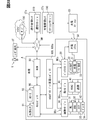
- the energy manager 100 according to the first embodiment of the present disclosure shown in FIGS. 1 and 2 is mounted on the vehicle A.
- the vehicle A is a BEV (Battery Electric Vehicle) equipped with a main battery 22 for traveling and traveling with the electric power of the main battery 22.
- the energy manager 100 has a function of a battery management device that manages the state of the main battery 22.
- the vehicle A is equipped with a DCM93, a navigation device 60, a user input unit 160, a plurality of consumption domains DEc, a power supply domain DEs, a charging system 50, and the like together with the above-mentioned energy manager 100.
- DCM (Data Communication Module) 93 is a communication module mounted on vehicle A.
- the DCM93 transmits and receives radio waves to and from the base station BS around the vehicle A by wireless communication in accordance with communication standards such as LTE (Long Term Evolution) and 5G.
- LTE Long Term Evolution
- 5G 5th Generationан ⁇ 93
- the DCM93 can send and receive information to and from the cloud server 190, the station manager 180, and the like through the network NW.
- the cloud server 190 is an information distribution server installed on the cloud, and distributes, for example, weather information, traffic jam information, and the like.
- the station manager 180 is an arithmetic system installed in the charge management center CTc.
- the station manager 180 is communicably connected to a large number of charging stations CS installed in a specific area through a network NW.
- the station manager 180 keeps track of station information for each charging station CS.
- the station information includes the installation location of the charging station CS, availability information indicating whether or not the charging station CS is in use, charging capacity information of the charger, and the like.
- the charging capacity information includes, for example, whether or not quick charging is possible, the corresponding charging standard, and the maximum output (kW) of quick charging.
- the charging station CS is an infrastructure facility that charges the main battery 22 for traveling mounted on the vehicle A. Each charging station CS charges the main battery 22 using AC power supplied through the power grid or DC power supplied from a photovoltaic power generation system or the like. Charging station CS is installed in each parking lot such as a shopping mall, a convenience store, and a public facility.
- the navigation device 60 is an in-vehicle device that provides route guidance to a destination set by the user.
- the navigation device 60 guides straight ahead, left / right turn, lane change, etc. at intersections, turnout points, merging points, etc. by displaying a screen and reproducing voice.
- the navigation device 60 can provide the energy manager 100 with information such as a distance to a destination, a vehicle speed in each traveling section, and a height difference as navigation information.
- the user input unit 160 is an operation device that accepts input operations by a user of vehicle A such as a driver.
- the user input unit 160 includes, for example, a user operation for operating the navigation device 60, a user operation for switching between starting and stopping of temperature control (described later), a user operation for changing various setting values related to the vehicle A, and the like. Is entered.
- the user input unit 160 can provide the energy manager 100 with input information based on the user operation.
- a steering switch provided on the spokes of the steering wheel, a switch and dial installed on the center console, and a voice input device for detecting the driver's utterance are mounted on the vehicle A as the user input unit 160.
- the touch panel or the like of the navigation device 60 may function as the user input unit 160.
- a user terminal such as a smartphone or a tablet terminal may function as a user input unit 160 by being connected to the energy manager 100 by wire or wirelessly (for example, Bluetooth, a registered trademark).
- the consumption domain DEc is a group of in-vehicle devices that realize various vehicle functions by using electric power such as the main battery 22.
- a group of in-vehicle devices including at least one domain manager and whose power consumption is controlled by the domain manager is defined as one consumption domain DEc.
- the plurality of consumption domains DEc include a travel control domain and an air conditioning control domain.
- the travel control domain is the consumption domain DEc that controls the travel of the vehicle A.
- the travel control domain includes a motor generator 31, an inverter 32, a steer control system 33, a brake control system 34, and a motion manager 30.
- the motor generator 31 is a drive source that generates a driving force for driving the vehicle A.
- the inverter 32 controls power running and regeneration by the motor generator 31.
- the inverter 32 converts the DC power supplied from the main battery 22 into three-phase AC power and supplies it to the motor generator 31 during power running by the motor generator 31.
- the inverter 32 can adjust the frequency, current, and voltage of AC power, and controls the generated driving force of the motor generator 31.
- the inverter 32 converts AC power into DC power and supplies it to the main battery 22.
- the steering control system 33 controls the steering of the vehicle A.
- the brake control system 34 controls the braking force generated in the vehicle A.
- the motion manager 30 integrally controls the inverter 32, the steering control system 33, and the brake control system 34, and realizes the running of the vehicle A according to the driving operation of the driver.
- the motion manager 30 functions as a domain manager of the travel control domain, and comprehensively manages the power consumption by each of the motor generator 31, the inverter 32, the steering control system 33, and the brake control system 34.
- the air conditioning control domain is a consumption domain DEc that performs air conditioning in the living room space of vehicle A and temperature control of the main battery 22.
- the air conditioning control domain includes an HVAC (Heating, Ventilation, and Air Conditioning) 41, a temperature control system 42, and a heat manager 40.
- HVAC Heating, Ventilation, and Air Conditioning
- a plurality of HVAC 41s may be installed in one vehicle A.
- the HVAC 41 is an electric air conditioner that heats, cools, and ventilates a living room space by using the electric power supplied from the main battery 22.
- the HVAC 41 includes a refrigeration cycle device, a blower fan, an electric heater, an air mix damper, and the like.
- the HVAC 41 can control a compressor, an electric heater, an air mix damper, and the like of a refrigeration cycle device to generate warm air and cold air.
- the HVAC 41 supplies the warm air or cold air generated by the operation of the blower fan to the living room space as air conditioning air.
- the temperature control system 42 is a system that cools or raises the temperature of the main battery 22.
- the temperature control system 42 may cool or raise the temperature of the motor generator 31, the inverter 32, and the like together with the main battery 22.
- the temperature control system 42 keeps the temperature of the electric traveling system within a predetermined temperature range by circulating the coolant heated or cooled by the HVAC 41.
- the temperature control system 42 is composed of a cooling circuit, an electric pump, a radiator, a chiller, a liquid temperature sensor, and the like.
- the cooling circuit is mainly composed of pipes installed so as to go around each configuration of the electric traveling system such as the main battery 22, the motor generator 31, and the inverter 32.
- the electric pump circulates the coolant filled in the piping of the cooling circuit.
- the battery heat transferred to the coolant is released to the outside air by the radiator or released to the refrigerant of the HVAC 41 by the chiller.
- the liquid temperature sensor measures the temperature of the coolant.
- the heat manager 40 is an in-vehicle computer that controls the operation of the HVAC 41 and the temperature control system 42.
- the heat manager 40 compares the set temperature of the air conditioning in the living room space with the measured temperature of the temperature sensor installed in the living room space, and controls the air conditioning operation of the HVAC 41.
- the heat manager 40 controls the temperature control operation of the HVAC 41 and the temperature control system 42 with reference to the measurement result by the liquid temperature sensor.
- the above heat manager 40 functions as a domain manager of the heat domain, and comprehensively manages the power consumption by each of the HVAC 41 and the temperature control system 42.
- the power supply domain DEs are a group of in-vehicle devices for enabling power supply to the consumption domain DEc.
- the power supply domains DEs like the consumption domain DEc, include at least one domain manager.
- the power supply domains DEs include a charging circuit 21, a main battery 22, a sub-battery 23, and a battery manager 20.
- the charging circuit 21 functions as a junction box that integrally controls the flow of electric power between each consumption domain DEc and each of the batteries 22 and 23 in cooperation with the battery manager 20.
- the charging circuit 21 supplies electric power from the main battery 22 and the sub-battery 23, and charges the main battery 22 and the sub-battery 23.
- the main battery 22 is a secondary battery capable of charging and discharging electric power.
- the main battery 22 includes an assembled battery including a large number of battery cells.
- the battery cell is, for example, a nickel metal hydride battery, a lithium ion battery, an all-solid-state battery, or the like.
- the electric power stored in the main battery 22 is mainly used for traveling the vehicle A and air-conditioning the living room space.
- the sub-battery 23 is a secondary battery capable of charging and discharging electric power, like the main battery 22.
- the sub-battery 23 is, for example, a lead storage battery.
- the battery capacity of the sub-battery 23 is less than the battery capacity of the main battery 22.
- the electric power stored in the sub-battery 23 is mainly used by auxiliary machinery and the like of the vehicle A.
- the battery manager 20 is an in-vehicle computer that functions as a domain manager of the power supply domain DEs.
- the battery manager 20 manages the power supplied from the charging circuit 21 to each consumption domain DEc.
- the battery manager 20 notifies the energy manager 100 of the remaining amount information about the main battery 22 and the sub battery 23.
- the charging system 50 supplies electric power to the power supply domain DEs and enables charging of the main battery 22.
- An external charger is electrically connected to the charging system 50 at the charging station CS.
- the charging system 50 outputs the charging power supplied through the charging cable to the charging circuit 21.
- the charging system 50 converts the AC power supplied from the normal charging charger into DC power and supplies it to the charging circuit 21.
- the charging system 50 outputs DC power supplied from the quick charging charger to the charging circuit 21.
- the charging system 50 has a function of communicating with a charger for quick charging, and controls the voltage supplied to the charging circuit 21 in cooperation with the control circuit of the charger.
- the energy manager 100 manages the power usage by each consumption domain DEc in an integrated manner.
- the energy manager 100 is realized by an in-vehicle computer 100a including a processing unit 11, a RAM 12, a storage unit 13, an input / output interface 14, and a bus connecting them.
- the processing unit 11 is hardware for arithmetic processing combined with the RAM 12.
- the processing unit 11 executes various processes for realizing the functions of the functional units described later by accessing the RAM 12.
- the storage unit 13 is configured to include a non-volatile storage medium.
- Various programs (battery management programs, etc.) executed by the processing unit 11 are stored in the storage unit 13.
- the energy manager 100 executes the battery management program stored in the storage unit 13 by the processing unit 11, and includes a plurality of functional units related to the state management of the main battery 22. Specifically, the energy manager 100 includes an external information acquisition unit 71, an internal information acquisition unit 72, a temperature simulation unit 74, and a temperature control control unit 75 as functional units based on the battery management program.
- the power supply to the in-vehicle computer 100a is continued even when the vehicle A is in a non-travelable state (for example, in an ignition off state). Therefore, the energy manager 100 can activate each functional unit and execute a predetermined process if it is necessary to execute the control even in the neglected period described later.
- the external information acquisition unit 71 and the internal information acquisition unit 72 acquire vehicle usage information that affects the state of the main battery 22 at the arrival point of the vehicle A.
- the destination is a parking lot or a waiting area where the vehicle A is left, a charging station CS, or the like.
- the state of the main battery 22 is, for example, the remaining amount, the temperature, and the like.
- the external information acquisition unit 71 acquires information provided from the outside of the vehicle A among the vehicle usage information that affects the state of the main battery 22.
- the external information acquisition unit 71 can acquire center information distributed by, for example, the station manager 180, the cloud server 190, or the like as vehicle usage information.
- the external information acquisition unit 71 acquires the usability information and the charging capacity information regarding the charger of the charging station CS from the station manager 180.
- the external information acquisition unit 71 acquires weather information, traffic congestion information, and the like from the cloud server 190.
- the meteorological information includes information indicating the outside air temperature, the amount of solar radiation, the amount of radiant heat from the road surface, the presence or absence of rainfall or snowfall, etc. on the traveling route set in the navigation device 60.
- the internal information acquisition unit 72 acquires the vehicle usage information generated inside the vehicle A among the vehicle usage information that affects the state of the main battery 22.
- the internal information acquisition unit 72 can acquire vehicle usage information provided by, for example, the navigation device 60, the power supply domain DEs, the consumption domain DEc, and the like.
- the internal information acquisition unit 72 acquires the above-mentioned navigation information from the navigation device 60.
- the navigation information includes information such as the number of traffic lights (number of stops) in addition to the distance to the destination (arrival place), the vehicle speed of each section, and the height difference.
- the internal information acquisition unit 72 acquires status information indicating the status of the power supply domain DEs from the battery manager 20.
- the status information includes remaining amount information, temperature information, and the like of the main battery 22 and the sub battery 23.
- the remaining amount information is, for example, the value of SOC (States Of Charge, the unit is "%").
- the internal information acquisition unit 72 acquires the driving tendency information of the driver driving the vehicle A from the exercise manager 30 as vehicle usage information.
- the driving tendency information is, for example, information indicating the driving tendency of the driver, and is information for predicting a running load.
- the driving tendency information includes at least information indicating the tendency of the driver's accelerator opening and brake pedal effort.
- the internal information acquisition unit 72 acquires input information of a user who uses the vehicle A such as a driver.
- the input information may be information input to the user input unit 160 by a user boarding the vehicle A, or information input by a user outside the vehicle A to a user terminal functioning as the user input unit 160. May be good. Further, the input information may be information input by the user in real time in response to an inquiry from the system side such as the energy manager 100, or may be information indicating a set value recorded by the user's past operation. ..
- the internal information acquisition unit 72 acquires real-time input information from the user input unit 160, and acquires user-set values based on past input information from the storage unit 13 and the like.
- the internal information acquisition unit 72 acquires status information indicating the status of each consumption domain DEc from each domain manager.
- the status information includes information indicating the operating state of each in-vehicle device.
- the internal information acquisition unit 72 acquires the set temperature of the air conditioner in the living room space (hereinafter, “air conditioner request information”) and the air conditioner information indicating the current temperature as status information. Further, the internal information acquisition unit 72 may acquire the temperature information of the coolant of the cooling circuit, the information indicating the state (for example, the current temperature, etc.) of the motor generator 31 and the inverter 32, etc. as the status information.
- the external information acquisition unit 71 and the internal information acquisition unit 72 acquire vehicle usage information, which is a future estimated value, in addition to the vehicle usage information, which is the current actual measurement value. More specifically, the vehicle A can have a future use schedule.
- the usage schedule includes a running schedule after leaving, a running schedule under a high load, a charging schedule, a running schedule after leaving the main battery 22 in a high temperature state, a running schedule after leaving in a low temperature, and the like.
- vehicle usage information is provided for each of the period from the present until the start of the usage schedule, the start of the usage schedule, and the period after the start of the usage schedule. To get.
- the information that affects the state of the main battery 22 before the start of the usage schedule is used as the prior impact information, and the information that affects the state of the main battery 22 at the start of the usage schedule is referred to as the start impact information. To do. Further, the vehicle usage information that affects the state of the main battery 22 after the start of the usage schedule is used as the post-effect information.
- the pre-impact information, start-time impact information and post-impact information are estimated or predicted values.
- the prior impact information is, for example, an estimated value of traffic information such as traveling load, air conditioning load, and congestion information from the present to the destination, and environmental information such as outside air temperature and amount of solar radiation.
- the start-time impact information is, for example, usability information such as the waiting time of the charger at the charging station CS.
- the ex-post impact information includes, for example, charging capacity information of the charger of the charging station CS, traveling load information after departure from the arrival place, and environmental information such as outside air temperature and solar radiation amount.
- the environmental information around the vehicle A acquired as the vehicle usage information can be included in both the pre-impact information and the post-impact information.
- the temperature simulation unit 74 is the target battery temperature Tb of the temperature control controlled for the main battery 22 based on the vehicle usage information acquired by the external information acquisition unit 71 and the internal information acquisition unit 72 (see FIG. 7 and the like). To set. The temperature simulation unit 74 sets an initial value of the target battery temperature Tb, and then repeats updating the target battery temperature Tb so as to reflect the newly acquired vehicle usage information. The temperature simulation unit 74 calculates the initial setting value, for example, when the vehicle A starts running, or when the vehicle A starts parking (leaving).
- the temperature simulation unit 74 calculates the initial setting value of the target battery temperature Tb by referring to the environmental information such as the outside air temperature and the amount of solar radiation, the remaining amount information and temperature information of the main battery 22, and the air conditioning information of the HVAC 41.
- the temperature simulation unit 74 initially sets the target battery temperature based on the new information acquired by the external information acquisition unit 71 and the internal information acquisition unit 72 among the pre-effect information, the start time effect information, and the post-effect information. Change from the value and update from time to time.
- the temperature simulation unit 74 has an execution determination unit 74a and a behavior learning unit 74b as sub-functional units.
- the implementation determination unit 74a determines whether or not to implement the temperature control control of the main battery 22.
- the implementation determination unit 74a refers to the remaining amount information of the main battery 22 acquired by the internal information acquisition unit 72, and determines that the temperature control is not necessary based on the decrease in the remaining amount of the main battery 22. For example, when the predicted value of the remaining battery level at the start or end of the above-mentioned usage schedule is lower than the predetermined remaining amount threshold value, the execution determination unit 74a determines not to execute the temperature control control. In addition, the execution determination unit 74a executes or does not execute the temperature control control of the main battery 22 based on the user's input information acquired by the internal information acquisition unit 72 by the input information acquisition process (see FIG. 6). decide.
- the behavior learning unit 74b learns the behavior tendency of the user who uses the vehicle A. Based on the behavior tendency of the user learned by the behavior learning unit 74b, the temperature simulation unit 74 predicts the use of the vehicle A. Specifically, the temperature simulation unit 74 can set the next travel start time and the like by reflecting the usage prediction based on the behavior tendency.
- the next driving start time is information included in the vehicle usage information as driver information (see FIG. 5).
- the temperature control unit 75 cooperates with the heat manager 40 to execute the temperature control of the main battery 22 determined by the temperature simulation unit 74.
- the temperature control unit 75 sets the distribution between the air conditioning capacity of the HVAC 41 and the temperature control capacity allocated to the temperature control system 42 based on the control command acquired from the temperature simulation unit 74, and achieves both air conditioning control and temperature control. Let me. In this way, the temperature control unit 75 cooperates with the temperature simulation unit 74 to arbitrate between the air conditioning capacity used for air conditioning of the living room space and the temperature control capacity used for temperature control of the main battery 22.
- the temperature simulation unit 74 grasps the upper limit of the refrigerating cycle capacity of the refrigerating cycle device of the HVAC 41.
- the temperature simulation unit 74 sets a temperature control control schedule, in other words, a control pattern for temperature control control, so that the total of the air conditioning requirement amount and the cooling request amount CP, which will be described later, does not exceed the refrigeration cycle capacity amount.
- FIGS. 1 to 6 show a list of a plurality of scenes for which read-ahead control is performed.
- FIG. 5 shows a list of vehicle usage information used for the look-ahead control in each scene in which the look-ahead control is performed.
- FIG. 6 shows an input information acquisition process executed as a sub-process of the look-ahead control process.
- the content of the input information acquired from the user input unit 160 is determined.
- the process proceeds from S22 to S27.
- S27 it is decided to carry out the temperature control control.
- the process proceeds from S22 to S28.
- S28 it is decided not to carry out the temperature control. Further, if there is no input operation by the user in response to the inquiry by the vehicle-mounted interface, the process proceeds from S22 to S23.
- the user terminal is used to further inquire whether to execute or cancel the temperature control.
- the user who possesses the user terminal used for inquiries may be on board the vehicle A or may be out of the vehicle. Also in this case, after the inquiry to the user, the acquisition of the input information transmitted from the user terminal based on the user operation is waited for a predetermined time.
- the content of the input information acquired from the user terminal is determined.
- the process proceeds from S24 to S27 to determine the execution of the temperature control control.
- the process proceeds from S24 to S28, and it is determined not to carry out the temperature control control. If there is no input operation by the user in response to the inquiry from the user terminal, the process proceeds from S24 to S25.
- the user-set information preset by the user is referred to.
- the user can register the above-mentioned user settings by inputting to the menu screen displayed on the navigation device 60 and the user terminal.
- S26 it is determined whether or not there is a user setting for canceling the temperature control control. If there is no user setting to cancel the temperature control, the process proceeds from S26 to S27 to determine the implementation of the temperature control. On the other hand, if there is a user U setting for canceling the temperature control, the process proceeds from S26 to S28, and it is determined not to perform the temperature control.
- Inquiries using the in-vehicle interface may be omitted in situations where the user is absent in the vehicle (for example, scenes 1 and 5 described later). Further, the inquiry using the user terminal may be omitted if the specific user terminal registered in the energy manager 100 does not exist. Further, it may be possible to set the user so as not to make an inquiry using the user terminal.
- ⁇ Scene 1 Before running (while left unattended)>
- scene 1 see TC1 in FIG. 3
- the energy manager 100 performs the look-ahead control shown in detail in FIGS. 7 to 9 to cool the main battery 22 before traveling. Cooling based on look-ahead control in scene 1 (hereinafter, "look-ahead cooling”) can exert effects such as improvement of drivability after running, improvement of electricity cost, removal of regenerative power, and suppression of deterioration of the main battery 22. ..
- the electric power used for the look-ahead cooling may be the electric power supplied by the external power source connected to the vehicle A. In this case, it is possible to suppress the consumption of the electric power stored in the main battery 22.
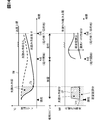
- the temperature simulation unit 74 predicts the time when the next travel starts based on the learning data of the user's usage tendency learned by the behavior learning unit 74b, and uses this travel start time (see point A in FIG. 7) as the vehicle. Get as information. As described above, the temperature simulation unit 74 sets the neglected schedule until the running start time and the running schedule after the running start time in relation to the usage schedule (see the middle stage of FIG. 7). The destination in this travel schedule corresponds to the destination.
- Vehicle usage information such as navigation information, center information, and driver information is used for pre-reading cooling of scene 1 (see FIG. 5, TC1 column).
- vehicle usage information information such as navigation information, traffic congestion information, accelerator opening, and brake pedal effort is used as prediction information (posterior impact information) during traveling.
- environmental information such as outside air temperature, amount of solar radiation, and amount of radiant heat is used as forecast information (pre-effect information and post-effect information) after the present.
- the above-mentioned running start time is used as prediction information (preliminary influence information) from the present to the start of running. Based on these vehicle usage information and the above usage schedule, the energy manager 100 repeatedly executes the look-ahead control process shown in FIG.
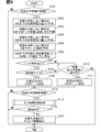
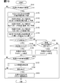
- S101 of the look-ahead control process in the scene 1 it is determined whether or not it is the execution cycle of the look-ahead prediction process. If it is determined in S101 that the execution cycle of the look-ahead prediction process is applicable, the process proceeds to S102. On the other hand, if it is determined that the execution cycle of the look-ahead prediction does not apply, the process proceeds to S112.
- S102 the total amount of power used up to the running start time (see point A in FIG. 7) when the look-ahead cooling is not performed is predicted, and the process proceeds to S103.
- vehicle usage information such as travel start time, outside air temperature, amount of solar radiation, and amount of radiant heat is used for calculating the total amount of electric power used.
- S102 may be omitted.
- S103 based on the total electric energy used calculated in S102, the state of the main battery 22 at the start time of running is predicted when the look-ahead cooling is not performed, and the process proceeds to S104.
- S103 the predicted values of the temperature and the remaining amount (SOC) of the main battery 22 are calculated (see the broken line from the present to the point A in FIG. 7).
- the total amount of power used up to the end time of running (see point O in FIG. 7) when the look-ahead cooling is not performed is predicted, and the process proceeds to S105.
- the total power consumption is calculated by using all the vehicle usage information except the running start time among the vehicle usage information (see FIG. 5 TC1 column) to be used in the scene 1.
- the cooling request amount CP (unit is “J”) and the target battery temperature Tb (unit is “° C.”) in the look-ahead cooling performed by the running start time. ) Is set, and the process proceeds to S107.
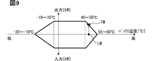
- the maximum power load LM (unit: “kW”) scheduled to be used in the travel schedule is applied to the correlation between the preset battery temperature and the input / output upper limit (see FIG. 9).
- the temperature upper limit TM of the main battery 22 is set.
- the cooling request amount CP (see the area in the shaded area in the lower row of FIG. 7) is calculated so that the battery temperature during running does not exceed the temperature upper limit TM.
- the necessity of pre-reading cooling is determined based on the remaining amount of the main battery 22.
- the remaining battery level at the end time of traveling when the look-ahead cooling is performed is predicted. If the predicted remaining amount is equal to or less than the predetermined remaining amount threshold value in S107, it is determined that the remaining battery level is insufficient, and the process proceeds to S110. On the other hand, in S107, when the predicted remaining amount exceeds the remaining amount threshold value, it is determined that the remaining amount of the battery is not insufficient, and the process proceeds to S108.
- the sum of the air conditioning requirement amount (unit is "J") of the living room space based on the air conditioning request information and the cooling request amount CP of the look-ahead cooling set in S106 is the refrigeration cycle capacity amount of HVAC41 (unit is "J"). It is determined whether or not it exceeds "J").
- the sum of the air conditioning required amount and the cooling required amount CP exceeds the refrigerating cycle capacity amount, it is determined that the cooling capacity is insufficient, and the process proceeds to S110.
- the sum of the air conditioning required amount and the cooling required amount CP is equal to or less than the refrigerating cycle capacity amount, it is determined that the cooling capacity is not insufficient, and the process proceeds to S109.
- the time schedule for pre-reading cooling is determined, and the process proceeds to S112.
- the air conditioning capacity used for cooling the living room space and the temperature control capacity used for look-ahead cooling are arbitrated, and the amount of look-ahead cooling performed (unit: “kW”) and the temperature control start time tcs are set.
- the amount of look-ahead cooling performed is set to a value corresponding to the difference between the maximum point of compressor efficiency in the refrigeration cycle device and the cooling capacity used for living room air conditioning.
- the time preceding the running start time by the time (sec) obtained by dividing the cooling request amount CP (J) by the pre-reading cooling amount (kW) is set as the temperature control start time tcs.
- the presence or absence of insufficient battery remaining amount and cooling capacity is re-determined as in S107 and S108. If it is determined in S110 that the remaining battery level at the end time of travel is equal to or less than the remaining amount threshold value even if the cooling request amount CP is reduced, the look-ahead control process is terminated. Similarly, if it is determined in S110 that the upper limit of the cooling capacity is exceeded even if the cooling request amount CP is reduced, the look-ahead control process is terminated.
- S110 determines whether the remaining battery level nor the cooling capacity is insufficient due to the reduction of the cooling required amount CP. If it is determined in S110 that neither the remaining battery level nor the cooling capacity is insufficient due to the reduction of the cooling required amount CP, the process proceeds to S111.
- S111 the time schedule for cooling execution is determined by the same method as in S109 so as to satisfy the cooling request amount CP reduced in S110, and the process proceeds to S112. It should be noted that S108 to S111 are processes for arbitrating the air conditioning capacity and the temperature control capacity in a broad sense.
- the temperature control start time tcs set in S109 or S111 is compared with the current time, and it is determined whether or not the pre-reading cooling implementation period has been reached. If it is determined in S112 that the pre-reading cooling is not performed, the pre-reading control process is terminated. On the other hand, if it is determined that the look-ahead cooling is performed, the process proceeds to S113.
- S114 it is determined whether or not to shift to S115 based on the decision result of implementation and non-execution by the input information acquisition process of S113. If it is determined in the input information acquisition process that the temperature control is not performed, the look-ahead control process is terminated. On the other hand, when it is decided to carry out the temperature control in the input information acquisition process, the process proceeds from S114 to S115.
- the drive instruction of the actuator is output to the heat manager 40 so that the main battery 22 is cooled, and the look-ahead control process is completed. To do. With S115, the thermal manager 40 starts battery cooling towards the target battery temperature Tb.
- scene 2 (see TC2 in FIGS. 3 and 4), the vehicle A is in a running state.
- the energy manager 100 performs look-ahead control, which is described in detail in FIGS. 10 and 11, to cool the main battery 22 before traveling.
- the look-ahead cooling in the scene 2 can exert effects such as improvement of drivability during high-load driving and suppression of deterioration of the main battery 22.
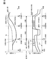
- the temperature simulation unit 74 determines the start time of the high-load traveling section (see point A in FIG. 10), the end time of the high-load traveling section (see point B in FIG. 10), and the arrival time at the destination (FIG. 10). 10 Refer to point O). Further, the temperature simulation unit 74 sets a normal traveling schedule and a traveling schedule with a high load in relation to the usage schedule (see the middle stage of FIG. 10). The destination in these travel schedules corresponds to the destination.
- Vehicle usage information such as navigation information, center information, and driver information is used for pre-reading cooling of scene 2 (see FIG. 5, TC2 column).
- scene 2 all the vehicle usage information to be used is used for the look-ahead control as the prediction information (pre-impact information and post-impact information) after the present.
- the energy manager 100 Based on these vehicle usage information and the above usage schedule, the energy manager 100 repeatedly executes the look-ahead control process shown in FIG.
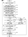
- S121 of the look-ahead control process in the scene 2 it is determined whether or not it is the execution cycle of the look-ahead prediction process. If it is determined in S121 that the execution cycle of the look-ahead prediction process is applicable, the process proceeds to S122. On the other hand, if it is determined that the execution cycle of the look-ahead prediction does not apply, the process proceeds to S132.
- S122 the total amount of power used up to the start time of the high-load traveling section (see point A in FIG. 10) when the look-ahead cooling is not performed is predicted, and the process proceeds to S123.
- all vehicle usage information see FIG. 5, TC2 column) to be used in scene 2 is used for calculating the total power consumption.
- S123 based on the total electric energy used calculated in S122, the state of the main battery 22 at the start time of the high-load traveling section when the look-ahead cooling is not performed is predicted, and the process proceeds to S124.
- the predicted values of the temperature and the remaining amount (SOC) of the main battery 22 are calculated (see the broken line from the present to the point A in FIG. 10).
- S124 the total amount of power used up to the end time of the arrival time of the destination is predicted when the look-ahead cooling is not performed, and the process proceeds to S125.
- S124 as well, as in S122, all vehicle usage information (see FIG. 5, TC2 column) to be used in scene 2 is used for calculating the total power consumption.
- the cooling request amount CP (unit is “J”) and the target battery temperature Tb in the look-ahead cooling to be performed by the start time of the high load running are set. ..
- the maximum power load LM (unit: “kW”) to be used in high-load driving is applied to the correlation between the preset battery temperature and the input / output upper limit (see FIG. 9).
- the cooling request amount CP (see the area in the shaded area in the lower part of FIG. 10) is calculated so that the battery temperature during high-load running does not exceed the temperature upper limit TM.
- S127 the necessity of pre-reading cooling is determined based on the remaining amount of the main battery 22.
- the remaining battery level at the time of arrival at the destination when the look-ahead cooling is performed is predicted. If the predicted remaining amount is equal to or less than the remaining amount threshold value in S127, it is determined that the remaining amount of the battery is insufficient, and the process proceeds to S130. On the other hand, in S127, when the predicted remaining amount exceeds the remaining amount threshold value, it is determined that the remaining amount of the battery is not insufficient, and the process proceeds to S128.
- the sum of the air conditioning requirement amount (unit is "J") of the living room space based on the air conditioning request information and the cooling request amount CP of the look-ahead cooling set in S126 is the refrigeration cycle capacity amount of HVAC41 (unit is "J"). It is determined whether or not it exceeds "J"). If the sum of the air conditioning required amount and the cooling required amount CP exceeds the refrigerating cycle capacity amount in S128, it is determined that the cooling capacity is insufficient, and the process proceeds to S130. On the other hand, if it is determined in S128 that the sum of the air conditioning required amount and the cooling required amount CP is equal to or less than the refrigeration cycle capacity amount, it is determined that the cooling capacity is not insufficient, and the process proceeds to S129.
- the time schedule for pre-reading cooling is determined, and the process proceeds to S132.
- the air conditioning capacity used for cooling the living room space and the temperature control capacity used for the look-ahead cooling are arbitrated, and the amount of the look-ahead cooling performed (unit: “kW”) and the temperature control start time tcs are set.
- the amount of pre-reading cooling performed is set to a value corresponding to the difference between the capacity upper limit of the refrigeration cycle device and the cooling capacity used for living room air conditioning.
- the time preceded from the start of the high-load traveling section by the time (sec) obtained by dividing the cooling request amount CP (J) by the pre-reading cooling amount (kW) is defined as the temperature control start time tcs.
- the presence or absence of insufficient battery remaining amount and cooling capacity is re-determined as in S127 and S128. If it is determined in S130 that the remaining battery level at the time of arrival at the destination is equal to or less than the remaining amount threshold value even if the cooling request amount CP is reduced, the look-ahead control process is terminated. Similarly, if it is determined in S130 that the sum of the air conditioning required amount and the cooling required amount CP exceeds the refrigerating cycle capacity amount even if the cooling required amount CP is reduced, the look-ahead control process is terminated.
- S131 the time schedule for cooling is determined by the same method as in S129 so as to satisfy the cooling request amount CP reduced in S130, and the process proceeds to S132. It should be noted that S128 to S131 are processes for arbitrating the air conditioning capacity and the temperature control capacity in a broad sense.
- the temperature control start time tcs set in S129 or S131 is compared with the current time, and it is determined whether or not the pre-reading cooling is performed. If it is determined in S132 that the pre-reading cooling is not performed, the pre-reading control process is terminated. On the other hand, if it is determined that the look-ahead cooling is performed, the process proceeds to S133.
- the above-mentioned input information acquisition process (see FIG. 6) is executed, a decision is made whether or not to implement the temperature control control based on the user's input information, and the process proceeds to S134.
- the inquiry using the user terminal (FIG. 6, S23) may be omitted in consideration of the fact that the user (driver) is driving. Further, when it is estimated that the operating load is high, the inquiry using the user input unit 160 (FIG. 6, S21) may be omitted.
- S134 it is determined whether or not to shift to S135 based on the decision result of implementation and non-execution by the input information acquisition process of S133. If it is determined in the input information acquisition process that the temperature control is not performed, the look-ahead control process is terminated. On the other hand, if it is decided to implement the temperature control in the input information acquisition process, the process proceeds from S134 to S135.
- the drive instruction of the actuator is output to the heat manager 40 so that the main battery 22 is cooled in addition to the cooling of the air conditioner in the living room, and the look-ahead control process is completed.
- the thermal manager 40 starts battery cooling towards the target battery temperature Tb.
- ⁇ Scene 3 Before charging (while driving)>
- scene 3 the vehicle A is in a running state and is in a state before charging the main battery 22.
- the energy manager 100 performs read-ahead control as detailed in FIGS. 12 and 13 to cool the main battery 22 before charging.
- the look-ahead cooling in the scene 3 can exert effects such as shortening the charging time by avoiding the input limitation (see FIG. 9) and suppressing deterioration of the main battery 22.
- the charging to be performed may be quick charging or normal charging. Before the start of rapid charging or normal charging, the target battery temperature corresponding to each charging mode is set.
- the temperature simulation unit 74 Based on the navigation information, the availability information of the charging station CS, and the charging capacity information, the temperature simulation unit 74 arrives at the charging station CS (see point A in FIG. 12), starts charging (see point B in FIG. 12), and Set the charging completion time (see point C in Fig. 12). Further, the temperature simulation unit 74 sets a traveling schedule from the present to the arrival time at the charging station CS, a standby schedule from the arrival time to the charging start time, and a charging schedule from the charging start time to the charging completion time (FIG. 12). See middle row). In this case, the charging station CS corresponds to the destination.
- Vehicle usage information such as navigation information, center information, and driver information is used for pre-reading cooling of scene 3 (see FIG. 5, TC3 column).
- vehicle usage information information such as navigation information, traffic congestion information, accelerator opening, and brake pedal effort is used as prediction information (preliminary impact information) during traveling.
- environmental information such as outside air temperature, amount of solar radiation, and amount of radiant heat is used as forecast information (pre-effect information, start-time effect information, and post-effect information) after the present.
- the above-mentioned charging capacity information is used as prediction information (posterior effect information) during charging.
- the above-mentioned usability information is used as prediction information (start time influence information) from the arrival time at the charging station CS to the charging start time.
- the energy manager 100 repeatedly executes the look-ahead control process shown in FIG.
- S141 of the look-ahead control process in the scene 3 it is determined whether or not it is the execution cycle of the look-ahead prediction process. If it is determined in S141 that the execution cycle of the look-ahead prediction process is applicable, the process proceeds to S142. On the other hand, if it is determined that the execution cycle of the look-ahead prediction does not apply, the process proceeds to S152.
- the charging standby time from the arrival time at the charging station CS to the charging start time is predicted based on the charging availability information (see FIG. 5 TC3 column) indicating the waiting time at the charging station CS, and the process proceeds to S143.
- S143 the total amount of power used up to the charging start time (see point B in FIG. 12) when the look-ahead cooling is not performed is predicted, and the process proceeds to S144.
- S143 of all the vehicle usage information (see FIG. 5 TC3 column) targeted for use in scene 3, all the information except the charging availability information and the charging capacity information is used for calculating the total power consumption. Will be done.
- S144 the state of the main battery 22 at the charging start time when the look-ahead cooling is not performed is predicted based on the total power consumption calculated in S143, and the process proceeds to S145.
- S145 the temperature transition of the main battery 22 in the market until the end time of charging is predicted when the look-ahead cooling is not performed (see the broken line in FIG. 12), and the process proceeds to S146.
- the charging capacity information is used as vehicle usage information.
- the cooling request amount CP (unit is “J”) and the target battery temperature Tb in the look-ahead cooling performed by the charging start time are set, and set to S147. move on.
- the cooling request amount CP (see the area in the shaded area in the lower part of FIG. 12) is calculated so that the battery temperature during charging does not exceed the temperature upper limit TM.
- the necessity of pre-reading cooling is determined based on the remaining amount of the main battery 22.
- the remaining amount of the main battery 22 at the time of arrival at the charging station CS is predicted. If the predicted remaining amount is equal to or less than the remaining amount threshold value in S147, it is determined that the remaining amount of the battery is insufficient, and the process proceeds to S150. On the other hand, if the predicted remaining amount exceeds the remaining amount threshold value in S147, it is determined that the remaining amount of the battery is not insufficient, and the process proceeds to S148.
- the sum of the air conditioning requirement amount (unit is "J") of the living room space based on the air conditioning request information and the cooling request amount CP of the look-ahead cooling set in S146 is the refrigeration cycle capacity amount of HVAC41 (unit is "J"). It is determined whether or not it exceeds "J").
- the sum of the air conditioning required amount and the cooling required amount CP exceeds the refrigerating cycle capacity amount, it is determined that the cooling capacity is insufficient, and the process proceeds to S150.
- the sum of the air conditioning required amount and the cooling required amount CP is equal to or less than the refrigerating cycle capacity amount, it is determined that the cooling capacity is not insufficient, and the process proceeds to S149.
- the time schedule for pre-reading cooling is determined, and the process proceeds to S152.
- the air conditioning capacity used for cooling the living room space and the temperature control capacity used for look-ahead cooling are arbitrated, and the amount of look-ahead cooling performed (unit: “kW”) and the temperature control start time tcs are set.
- the amount of pre-reading cooling performed is set to a value corresponding to the difference between the capacity upper limit of the refrigeration cycle device and the cooling capacity used for living room air conditioning.
- the time that precedes the arrival time at the charging station CS by the time (sec) obtained by dividing the cooling request amount CP (J) by the pre-reading cooling amount (kW) is the temperature control start time tcs. Will be done.
- the presence or absence of insufficient battery remaining amount and cooling capacity is re-determined as in S147 and S148. If it is determined in S150 that the remaining battery level at the time of arrival at the charging station CS is equal to or less than the remaining amount threshold value even if the cooling request amount CP is reduced, the look-ahead control process is terminated. Similarly, if it is determined in S150 that the sum of the air conditioning required amount and the cooling required amount CP exceeds the refrigerating cycle capacity amount even if the cooling required amount CP is reduced, the look-ahead control process is terminated.
- S150 determines whether the remaining battery level nor the cooling capacity is insufficient due to the reduction of the cooling required amount CP. If it is determined in S150 that neither the remaining battery level nor the cooling capacity is insufficient due to the reduction of the cooling required amount CP, the process proceeds to S151.
- S151 the time schedule for cooling execution is determined by the same method as in S149 so as to satisfy the cooling request amount CP corrected in S150, and the process proceeds to S152. It should be noted that S148 to S151 are processes for arbitrating the air conditioning capacity and the temperature control capacity in a broad sense.
- the temperature control start time tcs set in S149 or S151 is compared with the current time, and it is determined whether or not the pre-reading cooling is performed. If it is determined in S152 that the pre-reading cooling is not performed, the pre-reading control process is terminated. On the other hand, if it is determined that the look-ahead cooling is performed, the process proceeds to S153.
- the above-mentioned input information acquisition process (see FIG. 6) is executed, a decision is made whether or not to implement the temperature control control based on the user's input information, and the process proceeds to S154.
- the inquiry using the user terminal (FIG. 6, S23) may be omitted in consideration of the fact that the user (driver) is driving.
- S154 it is determined whether or not to shift to S155 based on the decision result of implementation and non-execution by the input information acquisition process of S153. If it is determined in the input information acquisition process that the temperature control is not performed, the look-ahead control process is terminated. On the other hand, if it is decided to carry out the temperature control in the input information acquisition process, the process proceeds from S154 to S155.
- the drive instruction of the actuator is output to the heat manager 40 so that the main battery 22 is cooled in addition to the cooling of the living room air conditioner, and the look-ahead control process is completed.
- the thermal manager 40 starts battery cooling toward the target battery temperature Tb.
- ⁇ Scene 4 At the start of leaving (after charging or running)>
- scene 4 the vehicle A is in a state of being left unattended, and is in a state after charging is completed or after running.
- the energy manager 100 performs read-ahead control as described in detail in FIGS. 14 and 15 to cool the main battery 22 before being left unattended.
- the look-ahead cooling in the scene 4 can exert an effect such as suppressing deterioration of the main battery 22.
- Even when normal charging is performed in parallel with leaving the battery the temperature transition of the main battery 22 during the normal charging period is predicted, and the target battery temperature Tb for cooling the main battery 22 during normal charging is set. May be done.
- Tb may be set. In these cases as well, cooling for the purpose of suppressing deterioration of the main battery 22 becomes possible.
- the temperature simulation unit 74 predicts the time when the next travel starts based on the learning data of the user's usage tendency learned by the behavior learning unit 74b, and uses this travel start time (see point A in FIG. 14) as the vehicle. Get as information. As described above, the temperature simulation unit 74 sets the neglected schedule until the running start time and the running schedule after the running start time in relation to the usage schedule (see the middle stage of FIG. 14).
- center information such as the outside air temperature, the amount of solar radiation and the amount of radiant heat, and vehicle usage information such as the next running start time are used (see FIG. 5, TC4 column).
- vehicle usage information environmental information such as temperature, amount of solar radiation, and amount of radiant heat is used as forecast information (pre-effect information and post-effect information) after the present.
- forecast information pre-effect information and post-effect information
- running start time is used as prediction information (preliminary influence information) from the present to the start of running.
- S161 of the look-ahead control process in the scene 4 it is determined whether or not it is the execution cycle of the look-ahead prediction process. If it is determined in S161 that the execution cycle of the look-ahead prediction process is applicable, the process proceeds to S162. On the other hand, if it is determined that the execution cycle of the look-ahead prediction does not apply, the process proceeds to S172.
- S162 the total amount of power used up to the running start time (see point A in FIG. 14) when the look-ahead cooling is not performed is predicted, and the process proceeds to S163.
- vehicle usage information such as the next travel start time, outside air temperature, solar radiation amount, and radiant heat amount is used for calculating the total power consumption.
- S162 may be omitted.
- the amount of battery deterioration in the market when the look-ahead cooling is not performed is predicted, and the process proceeds to S165.
- the battery deterioration amount calculated in S164 is compared with a predetermined threshold value (reference deterioration amount), and the degree of deterioration progress of the current main battery 22 is evaluated.
- the reference deterioration value is defined by, for example, the correlation between the usage period of the vehicle A and the reference SOH (States Of Health, the unit is "%").
- S164 when the value of SOH indicating the degree of deterioration of the current battery exceeds the SOH of the reference deterioration amount, it is estimated that the deterioration amount is small, and the look-ahead control process is terminated. On the other hand, in S164, when the current SOH value is equal to or less than the reference SOH, it is estimated that the amount of deterioration is large, and the process proceeds to S166.
- the cooling request amount CP (unit is “J”) and the target battery temperature Tb in the look-ahead cooling to be performed by the running start time are set, and the process proceeds to S167.
- the cooling request amount CP (see the area in the shaded area in the lower part of FIG. 14) is calculated so that the battery temperature during leaving is lower than, for example, the outside air temperature.
- S167 the necessity of pre-reading cooling is determined based on the remaining amount of the main battery 22.
- SOC the SOC of the traveling start time when the look-ahead cooling is performed is compared with the SOC (remaining amount threshold value) required for the vehicle A to reach the next joint. If the SOC of the main battery 22 is less than or equal to the SOC required to reach the destination, it is determined that the remaining battery level is insufficient, and the process proceeds to S170. On the other hand, in S167, when the SOC of the main battery 22 exceeds the required SOC, it is determined that the remaining battery level is not insufficient, and the process proceeds to S168.
- the sum of the air conditioning requirement amount (unit is "J") of the living room space based on the air conditioning request information and the cooling request amount CP of the look-ahead cooling set in S166 is the refrigeration cycle capacity amount of HVAC41 (unit is "J"). It is determined whether or not it exceeds "J").
- the sum of the required air conditioning amount and the required cooling amount CP exceeds the refrigerating cycle capacity amount, it is determined that the cooling capacity is insufficient, and the process proceeds to S170.
- the sum of the air conditioning required amount and the cooling required amount CP is equal to or less than the refrigerating cycle capacity amount, it is determined that the cooling capacity is not insufficient, and the process proceeds to S169.
- the time schedule for carrying out look-ahead cooling is determined, and the process proceeds to S172.
- the air conditioning capacity used for cooling the living room space and the temperature control capacity used for the look-ahead cooling are arbitrated, and the amount of the look-ahead cooling performed (unit: “kW”) and the temperature control start time tcs are set.
- the amount of look-ahead cooling performed is set to a value corresponding to the difference between the maximum point of compressor efficiency in the refrigeration cycle device and the cooling capacity used for living room air conditioning.
- the time that precedes the running start time by the time (sec) obtained by dividing the cooling request amount CP (J) by the pre-reading cooling amount (kW) is set as the temperature control start time tcs.
- S170 after multiplying the cooling request amount CP by a predetermined value of less than 1, the presence or absence of insufficient battery remaining amount and cooling capacity is re-determined as in S167 and S168. If it is determined in S170 that the remaining battery level at the end time of travel is equal to or less than the remaining amount threshold value even if the cooling request amount CP is reduced, the look-ahead control process is terminated. Similarly, if it is determined in S170 that the sum of the air conditioning required amount and the cooling required amount CP exceeds the refrigerating cycle capacity amount even if the cooling required amount CP is reduced, the look-ahead control process is terminated.
- S170 determines whether the remaining battery level nor the cooling capacity is insufficient due to the reduction of the cooling required amount CP. If it is determined in S170 that neither the remaining battery level nor the cooling capacity is insufficient due to the reduction of the cooling required amount CP, the process proceeds to S171.
- S171 the time schedule for cooling execution is determined by the same method as in S169 so as to satisfy the cooling request amount CP corrected in S170, and the process proceeds to S172.
- S168 to S171 are processes for arbitrating the air conditioning capacity and the temperature control capacity in a broad sense.
- the temperature control start time tcs set in S169 or S171 is compared with the current time, and it is determined whether or not the pre-reading cooling is performed. If it is determined in S172 that the pre-reading cooling is not performed, the pre-reading control process is terminated. On the other hand, if it is determined that the look-ahead cooling is performed, the process proceeds to S173.
- S173 the above-mentioned input information acquisition process (see FIG. 6) is executed, a decision is made whether or not to implement the temperature control control based on the user's input information, and the process proceeds to S174.
- S174 it is determined whether or not to shift to S175 based on the determination result of implementation and non-execution by the input information acquisition process of S173. If it is determined in the input information acquisition process that the temperature control is not performed, the look-ahead control process is terminated. On the other hand, if it is decided to carry out the temperature control in the input information acquisition process, the process proceeds from S174 to S175.
- the drive instruction of the actuator is output to the heat manager 40 so that the main battery 22 is cooled in addition to the cooling of the living room air conditioner, and the look-ahead control process is completed.
- the thermal manager 40 starts battery cooling toward the target battery temperature Tb.
- ⁇ Scene 5 Before driving (leaving in a low temperature environment)>
- vehicle A is in a state of being left in a low temperature environment.
- the energy manager 100 performs the look-ahead control shown in detail in FIGS. 16 to 18 to raise the temperature of the main battery 22 before traveling.
- the temperature rise of the main battery 22 is carried out by, for example, a heat pump, an electric heater (PTC heater), or the like. More specifically, the heat of the high temperature and high pressure refrigerant after the compressor of the HVAC 41 is transferred to the coolant of the temperature control system 42 via the heat exchanger. Further, the electric heater also raises the temperature of the coolant by the heat generated by the energization. The main battery 22 is heated by the coolant thus heated.
- look-ahead warm-up can exert effects such as improvement of drivability after the start of running, improvement of electricity cost, and removal of regenerative power.
- the power supplied by the external power source connected to the vehicle A may be used for the look-ahead warm-up. In this case, it is possible to suppress the consumption of the electric power stored in the main battery 22.
- the temperature simulation unit 74 predicts the time when the next travel starts based on the learning data of the user's usage tendency learned by the behavior learning unit 74b, and uses this travel start time (see point A in FIG. 16) as the vehicle. Get as information. As described above, the temperature simulation unit 74 sets the neglected schedule until the running start time and the running schedule after the running start time in relation to the usage schedule (see the middle stage of FIG. 16). The destination in this travel schedule corresponds to the destination.
- Vehicle usage information such as navigation information, center information, and driver information is used for the look-ahead warm-up of scene 5 (see FIG. 5, TC5 column).
- vehicle usage information information such as navigation information, traffic congestion information, accelerator opening, and brake pedal effort is used as prediction information (posterior impact information) during traveling.
- environmental information such as outside air temperature, amount of solar radiation, and amount of radiant heat is used as forecast information (pre-effect information and post-effect information) after the present.
- the above-mentioned running start time is used as prediction information (preliminary influence information) from the present to the start of running. Based on these vehicle usage information and the above usage schedule, the energy manager 100 repeatedly executes the look-ahead control process shown in FIG.
- S181 of the look-ahead control process in the scene 5 it is determined whether or not it is the execution cycle of the look-ahead prediction process. If it is determined in S181 that the execution cycle of the look-ahead prediction process is applicable, the process proceeds to S182. On the other hand, if it is determined that the execution cycle of the look-ahead prediction does not apply, the process proceeds to S192.
- S182 the total power consumption up to the running start time (see point A in FIG. 16) when the look-ahead warm-up is not performed is predicted, and the process proceeds to S183.
- vehicle usage information such as travel start time, outside air temperature, amount of solar radiation, and amount of radiant heat is used for calculating the total amount of electric power used.
- S182 may be omitted.
- the total amount of power used up to the end time of running (see point O in FIG. 16) when the look-ahead warm-up is not performed is predicted, and the process proceeds to S185.
- the total power consumption is calculated by using all the vehicle usage information except the running start time among the vehicle usage information (see FIG. 5 TC5 column) to be used in the scene 5.
- the warm-up requirement HP (unit is "J") and the target battery temperature Tb in the look-ahead warm-up to be carried out by the running start time are set. Proceed to S187.
- the maximum power load LM to be used in the travel schedule is applied to the correlation between the preset battery temperature and the input / output upper limit (see FIG. 18), and the temperature upper limit TM of the main battery 22 is applied. And the temperature lower limit TL is set.
- the warm-up request amount HP is calculated so that the battery temperature during running is maintained between the temperature upper limit TM and the temperature lower limit TL.
- S187 the remaining amount of the main battery 22 at the end time of running when the look-ahead warm-up is performed is predicted. If the predicted remaining amount is equal to or less than the predetermined remaining amount threshold value in S187, it is determined that the remaining battery level is insufficient, and the process proceeds to S190. On the other hand, in S187, when the predicted remaining amount exceeds the remaining amount threshold value, it is determined that the remaining amount of the battery is not insufficient, and the process proceeds to S188.
- the sum of the air-conditioning requirement amount (unit is "J") of the living room space based on the air-conditioning request information and the warm-up request amount HP of the look-ahead warm-up set in S186 is the heating capacity amount (unit) of HVAC41 or the like. Determines whether or not it exceeds "J").
- the sum of the air conditioning required amount and the warming required amount HP exceeds the heating capacity amount, it is determined that the heating capacity is insufficient, and the process proceeds to S190.
- the sum of the air conditioning required amount and the warming required amount HP is equal to or less than the heating capacity amount, it is determined that the heating capacity is not insufficient, and the process proceeds to S189.
- the time schedule for carrying out the look-ahead warm-up is determined, and the process proceeds to S192.
- the air conditioning capacity used for heating the living room space and the temperature control capacity used for the look-ahead warm-up are arbitrated, and the amount of the look-ahead warm-up performed (unit is “kW”) and the temperature control start time tcs are set. ..
- the time that precedes the running start time by the time (sec) obtained by dividing the warm-up request amount HP (J) by the read-ahead warm-up execution amount (kW) is set as the temperature control start time tcs.
- S190 after multiplying the warm-up request amount HP by a predetermined value of less than 1, the presence or absence of insufficient battery remaining amount and heating capacity is re-determined as in S187 and S188. If it is determined in S190 that the remaining battery level at the end time of travel is equal to or less than the remaining amount threshold value even if the warm-up request amount HP is reduced, the look-ahead control process is terminated. Similarly, if it is determined in S190 that the sum of the air conditioning required amount and the warming required amount HP exceeds the heating capacity even if the warm-up required amount HP is reduced, the look-ahead control process is terminated.
- S190 determines whether the remaining battery level nor the heating capacity is insufficient due to the reduction of the warm-up request amount HP. If it is determined in S190 that neither the remaining battery level nor the heating capacity is insufficient due to the reduction of the warm-up request amount HP, the process proceeds to S191.
- S191 the time schedule for warm-up execution is determined by the same method as in S189 so as to satisfy the warm-up request amount HP corrected in S190, and the process proceeds to S192.
- S188 to S191 are processes for arbitrating the air conditioning capacity and the temperature control capacity.
- the temperature control start time ths set in S189 or S191 is compared with the current time, and it is determined whether or not the pre-reading warm-up period has come. If it is determined in S192 that the pre-reading warm-up period is not in effect, the pre-reading control process is terminated. On the other hand, if it is determined that the read-ahead warm-up period is in effect, the process proceeds to S193.
- the above-mentioned input information acquisition process (see FIG. 6) is performed, a decision is made to implement or not implement the temperature control control based on the user's input information, and the process proceeds to S194.
- the inquiry using the user input unit 160 in the vehicle (FIG. 6, S21) may be omitted.
- the inquiry using the user terminal (FIG. 6, S23) may be omitted in a time zone such as midnight or early morning.
- S194 it is determined whether or not to shift to S195 based on the decision result of implementation and non-execution by the input information acquisition process of S193. If it is determined in the input information acquisition process that the temperature control is not performed, the look-ahead control process is terminated. On the other hand, if it is decided to implement the temperature control in the input information acquisition process, the process proceeds from S194 to S195.
- the actuator drive instruction is output to the heat manager 40 so that the temperature of the main battery 22 is raised, and the look-ahead control process is performed. finish.
- the heat manager 40 starts battery warm-up toward the target battery temperature Tb.
- the energy manager 100 has determined the necessity of temperature control based on the future prediction of the temperature transition of the main battery 22. In addition to the automatic temperature control based on the judgment of the system side, the energy manager 100 can perform the temperature control based on the user judgment. Further, the energy manager 100 can stop the temperature control control started by the judgment of the system side based on the judgment of the user.
- the manual operation process shown in FIG. 19 is started by the execution determination unit 74a, the temperature control control unit 75, and the like after the start of power supply to the energy manager 100, and is repeatedly executed in a predetermined cycle until the power supply is stopped. To.
- S31 of the manual operation process it is determined whether or not there is a user operation instructing the execution of the temperature control control.
- the user can input a user operation instructing execution and stop of the temperature control control to the user input unit 160. More specifically, an operation screen for inputting execution and stop of temperature control control is displayed on the display of the navigation device 60 or the user terminal that functions as the user input unit 160. The operation of tapping the operation button (icon) displayed on the operation screen is the user operation for instructing the execution of the temperature control control. If the user operation is accepted by using the user terminal capable of wireless communication with the energy manager 100, the user can instruct the execution of the temperature control control from outside the vehicle.
- S33 it is determined whether or not there is a user operation (hereinafter, stop operation) instructing the stop of the temperature control control. If it is determined in S33 that there is no input for the stop operation, the determination in S33 is repeated. As a result, the execution determination unit 74a is in a state of waiting for the stop operation by the user. At this time, the temperature control unit 75 continues the temperature control during execution. Even if the temperature control control is started at the discretion of the system side, the manual operation process can transition to the state of waiting for the stop operation by repeating the determination of S33.
- stop operation a user operation instructing the stop of the temperature control control control.
- the target battery temperature Tb of the temperature control controlled for the main battery 22 is set from the set initial value based on the vehicle usage information that affects the state of the main battery 22 at the destination. Be changed. Based on the above, the target battery temperature Tb can be updated to an appropriate value at any time based on the new vehicle usage information. Therefore, it is possible to reduce the excess or deficiency of the temperature adjustment of the main battery 22.
- At least one of prior impact information, start impact information, and post impact information is acquired as vehicle usage information. Based on the above, it becomes easy to secure the accuracy of the estimated value or the predicted value that predicts the state of the main battery 22 in the future. Therefore, the excess or deficiency of the temperature adjustment of the main battery 22 can be further reduced.
- the external information acquisition unit 71 and the internal information acquisition unit 72 of the first embodiment can acquire all of the prior impact information, the start impact information, and the post impact information as vehicle usage information. Then, the temperature simulation unit 74 updates the target battery temperature Tb at any time based on the acquired information among the pre-effect information, the start time effect information, and the post-effect information. According to the above, since the target battery temperature Tb is continuously updated, the excess or deficiency of the temperature adjustment of the main battery 22 is likely to be reduced.
- the environmental information around the vehicle A is acquired as the vehicle usage information, and the target battery temperature Tb is changed based on the environmental information. According to the above, even if the outside air temperature, the amount of solar radiation, the amount of radiant heat, etc. around the vehicle A change, the accuracy of predicting the state of the main battery 22 can be maintained high. Therefore, the temperature control of the main battery 22 with reduced waste and shortage is realized.
- the driver's driving tendency information specifically, the accelerator opening and the brake pedal effort, etc. are acquired as vehicle usage information, and the target battery temperature Tb considers the variation in the traveling load based on the driving tendency. And can be set.
- the accuracy of predicting the state of the main battery 22 can be maintained even higher even in the manually driven vehicle. Therefore, it becomes easier to realize just enough temperature control control.
- the implementation determination unit 74a determines whether to implement the temperature control control or not. Therefore, the energy manager 100 can control the temperature control of the main battery 22 only at an appropriate timing. In other words, the implementation of temperature control at improper timing can be avoided.
- the embodiment determination unit 74a of the first embodiment determines whether or not to implement the temperature control control based on the decrease in the remaining amount of the main battery 22. Specifically, the remaining amount of the main battery 22 at a predetermined time is predicted, and when the predicted remaining amount falls below the remaining amount threshold value, the temperature control control is stopped. Based on the above, the situation in which the vehicle A is out of power due to the power consumption associated with the temperature control can be appropriately avoided.
- the implementation determination unit 74a of the first embodiment determines whether or not to implement the temperature control control based on the user input information related to the temperature control control. That is, the user's intention is prioritized over the judgment on the system side in determining whether to implement the temperature control control or not. According to the above, when the future action schedule is suddenly changed, the user can cancel the implementation of the temperature control control proposed by the system side with a simple operation. As a result, the convenience of the user related to the temperature control is easily ensured.
- the embodiment determination unit 74a of the first embodiment can manually forcibly start the temperature control of the main battery 22 based on the execution operation of the user.
- the execution determination unit 74a can manually stop the temperature control control during execution based on the stop operation of the user. According to the above, even if the future action schedule changes frequently, the user can easily manage the implementation and non-execution of the temperature control according to the changed action schedule. As a result, the convenience of the user related to the temperature control is further improved.
- the internal information acquisition unit 72 acquires air conditioning request information regarding air conditioning in the living room space.
- the temperature control unit 75 cooperates with the temperature simulation unit 74 to arbitrate the air conditioning capacity used for air conditioning of the living room space and the temperature control capacity used for temperature control of the battery. According to the above, even if the look-ahead control for the main battery 22 is implemented, the comfort of the living space, the function of suppressing window fogging, and the like are not easily impaired. As a result, it becomes possible to make the most effective use of electric power in the entire moving vehicle A including the occupants.
- the temperature simulation unit 74 sets the target battery temperature Tb for cooling the main battery 22 and causes the vehicle A to perform look-ahead cooling before the vehicle A starts traveling. Based on the above, it is possible to ensure drivability after the start of traveling and efficiently recover the regenerative power to the main battery 22. Further, if the look-ahead cooling is carried out by an external electric power, the improvement of the electric power cost during traveling can be realized.
- the temperature transition of the main battery 22 after the start of leaving the vehicle A is predicted (see FIG. 14). Then, the temperature simulation unit 74 sets the target battery temperature Tb for cooling the main battery 22 after the vehicle A starts to be left unattended, and causes pre-reading cooling to be performed. Other than that, the temperature simulation unit 74 sets the target battery temperature Tb for cooling the main battery 22 and causes the pre-reading cooling to be performed even during the running before the start of the normal charging and during the normal charging. Based on the above, it is possible to suppress the cumulative deterioration of the main battery 22 due to exposure to a high temperature.
- the behavior learning unit 74b of the first embodiment learns the behavior tendency of the user who uses the vehicle A. Then, the temperature simulation unit 74 reflects the usage prediction based on the learned behavior tendency, and the duration of neglect or the running start time, and by extension, the temperature control start time tcs of the look-ahead cooling and the temperature control start time ths of the look-ahead warm-up. Can be set. According to the above, even if the next running start time is not set by the user's input operation, the energy manager 100 over-controls the temperature control of the main battery 22 at the timing when the user starts using the vehicle A. It can be completed without any shortage. The next running start time may be set by a user input operation, or may be set with reference to the user's schedule data.
- the temperature simulation unit 74 sets the target battery temperature Tb for cooling the main battery 22 prior to the increase in the traveling load in the high negative traveling section, and causes the pre-reading cooling to be performed. According to the above, it is possible to obtain the effects of ensuring drivability during high-load driving and suppressing deterioration of the main battery 22 by avoiding the output limitation on the high temperature side.
- the temperature simulation unit 74 sets the target battery temperature Tb for cooling the main battery 22 and causes the pre-reading cooling to be performed before the start of charging at the charging station CS. According to the above, it is possible to appropriately complete the temperature control of the main battery 22 at the timing when the user starts using the vehicle A. As a result, effects such as shortening the charging time by avoiding the input restriction and suppressing deterioration of the main battery 22 can be obtained.
- the availability information of the charger at the charging station CS is acquired as vehicle usage information.
- the temperature simulation unit 74 sets the target battery temperature Tb for pre-reading cooling in anticipation of the standby time at the charging station CS when charging cannot be started immediately after arrival based on the usability information.
- the temperature simulation unit 74 recognizes whether or not the charger at the destination can be used, and if the charger cannot be used immediately after arrival, decides to stop or suppress the look-ahead cooling. Therefore, the wasted power input to the look-ahead cooling can be reduced while moving to the charging station CS.
- the charging capacity information of the charger at the charging station CS is acquired as vehicle usage information.
- the temperature simulation unit 74 sets the target battery temperature Tb in the look-ahead cooling based on the charging capacity information.
- the larger the charging capacity (wattage) of the charger the larger the temperature rise during charging, and conversely, the smaller the charging capacity, the smaller the temperature rise. Therefore, according to the grasp of the charging capacity, the excess or deficiency of the temperature adjustment of the main battery 22 due to the look-ahead cooling can be appropriately reduced.
- the effect of look-ahead cooling on traveling and air conditioning in the period until arrival at the charging station CS can be appropriately reduced.
- the temperature simulation unit 74 takes the charging capacity of the charger (for example, 3 kW or 5 kW, etc.) as an input, and stores in advance a calculation formula or a look-up table for determining the target battery temperature Tb.
- the temperature simulation unit 74 sets the target battery temperature Tb for raising the temperature of the main battery 22 before the vehicle A starts traveling, and causes the look-ahead warm-up to be performed. Based on the above, it is possible to obtain effects such as ensuring drivability during traveling by avoiding the output limitation on the low temperature side and efficiently recovering the regenerative power to the main battery 22. Further, if the look-ahead warm-up is carried out by external electric power, improvement of electric power cost during traveling can be realized.
- the processing unit 11 corresponds to the "processor”
- the main battery 22 corresponds to the "battery”
- the charging station CS corresponds to the "charging facility”.
- the in-vehicle computer 100a corresponds to the "computer”
- the energy manager 100 or the in-vehicle computer 100a corresponds to the "battery management device”.
- the external information acquisition unit 71 and the internal information acquisition unit 72 correspond to the "information acquisition unit”
- the temperature simulation unit 74 corresponds to the "target setting unit”
- the temperature control control unit 75 corresponds to the "capacity mediation unit”.
- the target battery temperature Tb corresponds to the "target battery temperature”.
- the second embodiment of the present disclosure shown in FIGS. 20 to 26 is a modification of the first embodiment.
- the vehicle A equipped with the energy manager 100 is a service car used in the mobility service system, and is an autonomous driving vehicle capable of autonomously traveling without any driving operation by the driver.
- the mobility service system is constructed by a plurality of vehicles A, a station manager 180, an operation manager 110, and the like.
- the operation of a plurality of vehicles A is managed by the operation manager 110, and the vehicle A provides a moving space to the user U.
- the plurality of vehicles A, the station manager 180, and the operation manager 110 are each connected to the network NW, and can transmit and receive information to and from each other.
- the details of the operation manager 110 and the vehicle A of the second embodiment will be described in order.
- the operation manager 110 is installed in, for example, an operation management center CTo or the like.
- the operation manager 110 manages the allocation of the vehicle A to the user U.
- the operation manager 110 acquires the user information of the user U who wants to use the mobility service for vehicle allocation management.
- the user information includes at least ID information that identifies the user U, a boarding place and a disembarking place of the user U, a scheduled boarding time (scheduled boarding time zone), and the like as information necessary for using the mobility service.
- the user U inputs user information using, for example, a smartphone, a tablet terminal, a personal computer, or the like as the user terminal UT.
- the operation manager 110 formulates an operation plan for each vehicle A based on the acquired user information.
- the operation plan includes information indicating how many users U get on and off at which place on the travel route.
- the operation manager 110 transmits the formulated operation plan to each vehicle A as a vehicle allocation instruction to the user U.
- the operation plan corresponds to the navigation information of the first embodiment, and includes information such as the distance to the destination, the vehicle speed in each traveling section, and the height difference.
- the operation manager 110 is an arithmetic system mainly composed of at least one server device.
- the server device includes a processing unit 111, a RAM 112, a storage unit 113, an input / output interface 114, a bus connecting these, and the like, and operates as an operation manager 110.
- the processing unit 111 is hardware for arithmetic processing combined with the RAM 112.
- the processing unit 111 executes various processes related to vehicle allocation management and the like by accessing the RAM 112.
- the storage unit 113 is configured to include a non-volatile storage medium.
- the storage unit 113 stores various programs executed by the processing unit 111.
- Vehicle A is equipped with an external sensor 91, a locator 92, an AD (Automated Driving) computer 90, and the like as a configuration for enabling autonomous driving.
- the external sensor 91 includes, for example, a camera unit, a rider, a millimeter wave radar, a sonar, and the like.
- the outside world sensor 91 generates object information that detects an object around the vehicle.
- the locator 92 receives positioning signals from a plurality of positioning satellites of the satellite positioning system, and generates position information of the vehicle A based on each received positioning signal.
- the AD computer 90 cooperates with the operation manager 110 to realize autonomous driving of the vehicle A based on the operation plan.
- the AD computer 90 acquires the operation plan transmitted by the operation manager 110 through the DCM93.
- the AD computer 90 recognizes the traveling environment around the vehicle A based on the object information acquired from the external sensor 91, the position information acquired from the locator 92, and the like, and the planned traveling route for traveling the vehicle A according to the operation plan. To generate.
- the AD computer 90 generates a control command based on the planned travel route and sequentially outputs the control command to the exercise manager 30.
- the motion manager 30 integrally controls the inverter 32, the steering control system 33, the brake control system 34, and the like based on the control command acquired from the AD computer 90, and autonomously drives the vehicle A so as to trace the planned travel route. ..
- the main battery 22 mounted on the vehicle A is used to maintain the stability of the system voltage in the power transmission and distribution network. More specifically, in recent years, power from renewable energy power generation such as solar power generation and wind power generation has been supplied to the power transmission and distribution network. The amount of such renewable energy power generation fluctuates greatly depending on the weather conditions. If there is a surplus or shortage of grid power due to an increase or decrease in the amount of power generation, a power outage may occur due to the grid voltage exceeding the permissible range.
- the energy manager 100 acquires a charge request from the system power to the main battery 22 or a power supply request from the main battery 22 to the system power by the external information acquisition unit 271.
- the external information acquisition unit 271 may acquire a charge request and a power supply request from, for example, a cloud server 190 of an electric power company provided on the cloud, and acquire a charge request and a power supply request together with an operation plan from the operation manager 110. May be good.
- the energy manager 100 sets the target battery temperature Tb of the temperature control to be performed on the main battery 22 by the temperature simulation unit 74 based on the charge request or the power supply request acquired by the external information acquisition unit 271.
- Tb of the temperature control to be performed on the main battery 22 by the temperature simulation unit 74 based on the charge request or the power supply request acquired by the external information acquisition unit 271.
- FIGS. 20 and 21 details of the main process and the plurality of sub-processes performed by the energy manager 100 will be described with reference to FIGS. 20 and 21 based on FIGS. 22 to 26. explain.
- the main processing and each sub processing shown in FIGS. 22 to 26 are continuously performed by the energy manager 100 being activated.
- a judgment as to whether or not to receive the cooperation request obtained in S21 is obtained.
- the decision on whether or not to respond to the cooperation request is made by the mobility service operator, the owner of vehicle A, or the like.
- the approval / disapproval determination may be performed according to a preset determination logic. Alternatively, an inquiry may be made to the owner or the like for each request for cooperation, and a decision on whether or not to accept the request may be made based on the input of the owner or the like. If it is determined in S22 that a cooperation request will be received, the process proceeds to S23. On the other hand, if it is determined that the cooperation request is not received, the process proceeds to S25.
- the designated point designated in the cooperation request is set as the destination where the vehicle A is moved, and the process proceeds to S24.
- a specific charging station CS that can be connected to the grid power is designated as a designated point.
- the target electric energy to be received or delivered at the destination is further acquired from the cloud server 190 or the like, and the process proceeds to S25.
- the amount of electric power required for traveling to the destination is calculated by the sub-processing shown in FIG. In the sub-processes S251 to S257 shown in FIG. 23, various vehicle usage information is acquired.
- S251 the battery temperature at the current time is acquired, and the process proceeds to S252.
- S252 the outside air temperature at the current time is acquired, and the process proceeds to S253.
- S253 the coolant temperature (water temperature) of the temperature control system 42 at the current time is acquired, and the process proceeds to S254.
- the mileage from the current location to the arrival location is acquired based on the travel plan acquired from the operation manager 110, and the process proceeds to S255.
- the current estimated time of arrival is acquired while referring to the traffic information and the like, and the process proceeds to S256.
- the outside air temperature coefficient of the current time is acquired based on the outside air temperature acquired in S252, and the process proceeds to S257.
- the driving inefficiency coefficient of the current driver is acquired based on the driver information, and the process proceeds to S258. When the vehicle A autonomously travels to the destination, S257 is omitted.
- the charging capacity at the destination is calculated by the sub-processing shown in FIG. 24.
- S261 of the sub-processing shown in FIG. 24 the availability information of the charging station CS, which is the destination, is acquired, the availability of the charger (for example, the number of free chargers, etc.) is grasped, and the process proceeds to S262.
- the charging capacity information of the empty charger is acquired, the power capacity (unit: "kW") of this charger is grasped, and the process proceeds to S263.
- the power capacity of the empty charger acquired in S262 is set as the charging capacity of the destination, and the process proceeds to S27 of the main process shown in FIG.
- the battery temperature reached at the destination (corresponding to the target battery temperature Tb in FIG. 12) is calculated by the sub-processing shown in FIG.
- the estimated value of the remaining battery level when arriving at the arrival place is calculated, the remaining battery level is acquired as the remaining power amount, and the process proceeds to S272.
- the electric power capacity of the vacant charger is acquired as the charging capacity of the destination, and the process proceeds to S273.
- the outside air temperature coefficient at the current time is acquired by calculation, and the process proceeds to S274.
- the temperature rise coefficient due to charging (unit: “° C./h”) is acquired, and the process proceeds to S276.
- the limiter temperature for quick charging (corresponding to the temperature upper limit TM, see FIG. 12) is acquired from the correlation between the battery temperature and the input / output upper limit (see FIG. 9), and the process proceeds to S277.
- the battery temperature reached at the destination is calculated by a calculation process (see Equation 3) in which the value obtained by multiplying the charging time by the temperature rise coefficient is subtracted from the limiter temperature of the quick charge, and is shown in FIG. Proceed to S28 of the main process.
- Limiter temperature for quick charging [° C]-(Charging time [h] x Temperature rise coefficient [° C / h]) Battery temperature [° C] reached at the destination ... (Equation 3)
- the control pattern of the battery temperature to the destination is calculated by the sub-processing shown in FIG.
- the battery temperature, the outside air temperature, and the coolant temperature at the current time are acquired in order in the same manner as in S251 to S253 (see FIG. 23), and the process proceeds to S284.
- S284 the amount of electric power required for traveling to the destination is acquired by referring to the calculation result of S258 (see FIG. 23), and the process proceeds to S285.
- S285 similarly to S272 (see FIG. 25)
- the charging capacity of the destination is acquired, and the process proceeds to S286.
- S286 the battery temperature reached at the destination is acquired by referring to the calculation result of S277 (see FIG. 25), and the process proceeds to S287.
- S287 it is determined whether the look-ahead temperature control is implemented or not.
- S287 it is determined whether or not the charging capacity of the charger to be used at the destination is higher than the predetermined value X (unit is “kWh”).
- the predetermined value X unit is “kWh”.
- the temperature control control is set to be suspended, and the process proceeds to S290.
- S289 the temperature control is set to be performed, and the process proceeds to S290.
- a temperature control control pattern to the destination (see the solid line in FIG. 12) is set by arithmetic processing that adds the amount of power required for air conditioning to the destination to the amount of power required to travel to the destination. Proceed to S29 of the main process shown in FIG. In S29, the pre-reading cooling of the main battery 22 is performed in cooperation with the temperature control unit 75 and the heat manager 40 according to the control pattern of the temperature control control set in S28.
- the target battery temperature Tb of the temperature control controlled for the main battery 22 is set based on the request for charging the main battery 22 or the request for supplying power from the main battery 22. Therefore, after the main battery 22 is connected to the grid power, charging from the grid power to the main battery 22 or power supply from the main battery 22 to the grid power can be performed without limitation. According to the above, in order to stabilize the system power, it is possible to reduce the excess or deficiency of the temperature adjustment of the main battery 22 even in the scene where the main battery 22 of the vehicle A is used.
- the external information acquisition unit 271 corresponds to the "request acquisition unit".
- the energy manager 100 can set the target battery temperature Tb if at least one of these pieces of information can be obtained. Further, the type of vehicle usage information used for setting the target battery temperature Tb may be changed as appropriate. For example, environmental information and driving tendency information may not be acquired. In addition, the availability information and charging capacity information of the charging station CS may not be acquired.
- vehicle usage information such as navigation information, center information, and driver information does not have to be obtained from the information sources described in the above embodiments, and is derived from the most desirable information source in each era regardless of the server side or the edge side. May be obtained.
- the station manager 180 and / and the navigation device 60 may be the information source of the charging capacity information.
- the temperature control is stopped based on the decrease in the remaining amount of the main battery 22. It is not necessary to carry out such determination of necessity of temperature control. Further, the temperature control may be stopped under conditions other than the decrease in the remaining battery level. Further, the arbitration between the air conditioning capacity and the temperature control capacity does not have to be carried out. For example, the air conditioning of the living room space may always be prioritized, or the temperature control of the main battery 22 may always be prioritized.
- an independent cooling circuit for cooling the main battery 22 is formed by the temperature control system 42.
- the specific temperature control configuration for cooling the main battery 22 is not limited to the water-cooled configuration as described above, and may be appropriately changed.
- an air-cooled temperature control configuration is adopted.
- the main battery 22 is cooled by the air inside the vehicle, the air cooled by the battery-dedicated air conditioner, the air introduced from the outside of the vehicle, and the like.
- the temperature control configuration of the refrigerant cooling method is adopted.
- the low-temperature and low-pressure refrigerant after the expansion valve is used for cooling the main battery 22 (refrigerant direct cooling method).
- the heat transferred from the main battery 22 to the refrigerant of the refrigeration cycle is dissipated from the condenser to the outside air.
- an independent refrigerant circuit for cooling the battery is formed in the temperature control system 42. The battery heat is transferred to the refrigerant circuit of the HVAC 41 by the heat exchanger provided between the HVAC 41 and the temperature control system 42, and is discharged from the condenser to the outside air (thermosiphon method).
- the configuration for raising the temperature of the main battery 22 can be changed as appropriate.
- a sheet-shaped heater for raising the temperature of the main battery 22 is installed on the bottom surface of the main battery 22.
- the main battery 22 is directly heated by energizing the heater.
- Vehicles A of the modified examples 5 and 6 of the first embodiment are service cars whose operation is managed by the operation manager 110.
- the functions of the battery management device are distributed and implemented in the on-board energy manager 100 and the operation manager 110 outside the vehicle. Further, in the modification 6, all the functions of the battery management device are implemented in the operation manager 110 outside the vehicle.
- an example of performing look-ahead temperature control is described based on a request for cooperation from the cloud on the premise of a service car used for providing mobility services.
- vehicles to which look-ahead temperature control based on a request for cooperation from the cloud can be applied are not limited to service cars.
- the above-mentioned look-ahead temperature control may be applied even to a personally owned POV (Personally owned Vehicle).
- the vehicle that can receive the cooperation request may be a manually operated vehicle that is not equipped with the AD computer 90 or the like.
- the vehicle A was able to respond to both the request for charging the main battery 22 from the system power and the request for supplying power from the main battery 22 to the system power.
- the vehicle A may be able to respond to only one of the charging request and the power supply request.
- look-ahead temperature control was performed in a plurality of scenes.
- the scene in which the look-ahead temperature control is performed may be changed as appropriate.
- the start timing and the end timing of each temperature control implementation period may be changed as appropriate.
- only one of the look-ahead cooling and the look-ahead warm-up may be carried out.
- the look-ahead control process based on the prediction of the temperature transition of the main battery 22 is omitted.
- the energy manager 100 of the modification 7 proposes to the user to perform temperature control control based on the status information such as the remaining amount information and the temperature information of the main battery 22 acquired by the internal information acquisition unit 72.
- the energy manager 100 of the modification 7 proposes cooling or raising the temperature of the main battery 22 based on the current SOC of the main battery 22.
- the energy manager 100 determines whether or not to implement the temperature control control based on the input operation of execution or cancellation by the user.
- the proposal for implementing temperature control by the energy manager 100 may be implemented when the battery temperature exceeds a specific threshold value or falls below a specific threshold value based on the current battery temperature of the main battery 22. .. Further, the temperature control implementation proposal may be implemented based on both the SOC of the main battery 22 and the battery temperature.
- the user, the operator, or the like receives the determination of the temperature control by the energy manager 100, and the user, the operator, or the like makes the final determination of the execution and cancellation of the temperature control. Do. Further, in the modification 9 of the above embodiment, the process of inquiring the user's judgment is omitted, and the implementation and non-execution of the temperature control control are finally decided based on the look-ahead control of the energy manager 100.
- the user can set the degree (strength) of the temperature control control in addition to the determination of execution and cancellation of the temperature control control.
- the user can perform a temperature control control weaker than the content set by the energy manager 100 when the future action schedule is fluid.
- Vehicle specifications such as the size of vehicle A and the passenger capacity may be changed as appropriate.
- the vehicle A may be a large vehicle such as an eight-wheeled vehicle or a six-wheeled vehicle in order to increase the capacity of the main battery 22 and the passenger capacity.
- the mounting capacity of the main battery 22, the number of mounted HVAC 41s, and the refrigerating cycle capacity may be appropriately changed according to the specifications of the vehicle A.
- the vehicle A is not limited to the battery EV described above, and may be a plug-in hybrid EV or a range extender EV.
- an internal combustion engine for power generation and a motor generator are provided in the charging system 50. Then, the charging system 50 can supply electric power for charging to the charging circuit 21 according to the decrease in the remaining amount of the main battery 22 even when the charging system 50 is not connected to the charger, for example, while the vehicle A is traveling.
- each function provided by the in-vehicle computer 100a, each server device, or the like can be provided by software and hardware for executing the software, software only, hardware only, or a combination thereof. Is. Further, when such a function is provided by an electronic circuit as hardware, each function can also be provided by a digital circuit including a large number of logic circuits or an analog circuit.
- Each of the processing units 11 and 111 of the above embodiment may have a configuration including at least one arithmetic core such as a CPU (Central Processing Unit) and a GPU (Graphics Processing Unit). Further, the processing units 11 and 111 may further include an FPGA (Field-Programmable Gate Array), an NPU (Neural network Processing Unit), an IP core having other dedicated functions, and the like.
- arithmetic core such as a CPU (Central Processing Unit) and a GPU (Graphics Processing Unit).
- the processing units 11 and 111 may further include an FPGA (Field-Programmable Gate Array), an NPU (Neural network Processing Unit), an IP core having other dedicated functions, and the like.
- the form of the storage medium that is adopted as each of the storage units 13 and 113 of the above embodiment and stores the battery management program that realizes the battery management method of the present disclosure may be appropriately changed.
- the storage medium is not limited to the configuration provided on the circuit board, and may be provided in the form of a memory card or the like, inserted into the slot portion, and electrically connected to the bus of the computer.
- the storage medium may be an optical disk and a hard disk drive that serve as a copy base for the program to the computer.
- control unit and its method described in the present disclosure may be realized by a dedicated computer constituting a processor programmed to execute one or a plurality of functions embodied by a computer program.
- the apparatus and method thereof described in the present disclosure may be realized by a dedicated hardware logic circuit.
- the apparatus and method thereof described in the present disclosure may be realized by one or more dedicated computers configured by a combination of a processor that executes a computer program and one or more hardware logic circuits.
- the computer program may be stored in a computer-readable non-transitional tangible recording medium as an instruction executed by the computer.
Landscapes
- Engineering & Computer Science (AREA)
- Power Engineering (AREA)
- Mechanical Engineering (AREA)
- Transportation (AREA)
- Life Sciences & Earth Sciences (AREA)
- Sustainable Energy (AREA)
- Sustainable Development (AREA)
- Manufacturing & Machinery (AREA)
- General Chemical & Material Sciences (AREA)
- Electrochemistry (AREA)
- Chemical Kinetics & Catalysis (AREA)
- Chemical & Material Sciences (AREA)
- Automation & Control Theory (AREA)
- Electric Propulsion And Braking For Vehicles (AREA)
Abstract
Selon la présente invention, un gestionnaire d'énergie fonctionne en tant que dispositif de gestion de batterie et gère l'état d'une batterie principale pour la conduite montée sur un véhicule. Le gestionnaire d'énergie acquiert des informations d'utilisation de véhicule qui affectent l'état de la batterie principale à l'emplacement d'arrivée du véhicule, par exemple à la destination et autres. Le gestionnaire d'énergie change la température de batterie cible (Tb) de la batterie principale à partir de la valeur initiale réglée, sur la base des informations d'utilisation de véhicule acquises.
Priority Applications (2)
| Application Number | Priority Date | Filing Date | Title |
|---|---|---|---|
| DE112020003709.6T DE112020003709T5 (de) | 2019-08-07 | 2020-07-16 | Batterieverwaltungsvorrichtung, Batterieverwaltungsverfahren und Batterieverwaltungsprogramm |
| CN202080059599.XA CN114340924B (zh) | 2019-08-07 | 2020-07-16 | 电池管理装置、电池管理方法及存储介质 |
Applications Claiming Priority (4)
| Application Number | Priority Date | Filing Date | Title |
|---|---|---|---|
| JP2019145721 | 2019-08-07 | ||
| JP2019-145721 | 2019-08-07 | ||
| JP2020-101757 | 2020-06-11 | ||
| JP2020101757A JP7294245B2 (ja) | 2019-08-07 | 2020-06-11 | バッテリ管理装置、バッテリ管理方法及びバッテリ管理プログラム |
Publications (1)
| Publication Number | Publication Date |
|---|---|
| WO2021024732A1 true WO2021024732A1 (fr) | 2021-02-11 |
Family
ID=74503044
Family Applications (1)
| Application Number | Title | Priority Date | Filing Date |
|---|---|---|---|
| PCT/JP2020/027593 Ceased WO2021024732A1 (fr) | 2019-08-07 | 2020-07-16 | Dispositif de gestion de batterie, procédé de gestion de batterie et programme de gestion de batterie |
Country Status (3)
| Country | Link |
|---|---|
| CN (1) | CN114340924B (fr) |
| DE (1) | DE112020003709T5 (fr) |
| WO (1) | WO2021024732A1 (fr) |
Cited By (9)
| Publication number | Priority date | Publication date | Assignee | Title |
|---|---|---|---|---|
| CN113492663A (zh) * | 2021-07-22 | 2021-10-12 | 上汽通用五菱汽车股份有限公司 | 动力电池加热方法、车辆及可读存储介质 |
| CN114604140A (zh) * | 2022-04-18 | 2022-06-10 | 柳州城市职业学院 | 一种基于云管控的新能源汽车统一调温系统及方法 |
| JP7295982B1 (ja) | 2022-02-04 | 2023-06-21 | 本田技研工業株式会社 | 充電制御システム |
| CN116476699A (zh) * | 2022-01-24 | 2023-07-25 | 本田技研工业株式会社 | 电池温度调节系统 |
| JP2024070554A (ja) * | 2022-11-11 | 2024-05-23 | 本田技研工業株式会社 | バッテリの温調方法、及び制御装置 |
| CN119142204A (zh) * | 2023-06-16 | 2024-12-17 | 北京罗克维尔斯科技有限公司 | 能量管理方法、装置、设备、存储介质及车辆 |
| CN119974900A (zh) * | 2025-03-28 | 2025-05-13 | 东风汽车股份有限公司 | 一种固定运行场景的热管理方法、装置、设备及存储介质 |
| WO2025262733A1 (fr) * | 2024-06-17 | 2025-12-26 | 日産自動車株式会社 | Procédé de commande de charge et dispositif de commande de charge |
| EP4628354A4 (fr) * | 2022-12-01 | 2026-01-07 | Nissan Motor | Procédé de commande d'un véhicule électrique et système de commande d'un véhicule électrique |
Families Citing this family (8)
| Publication number | Priority date | Publication date | Assignee | Title |
|---|---|---|---|---|
| KR20230165960A (ko) * | 2022-05-27 | 2023-12-06 | 현대자동차주식회사 | 차량의 배터리 컨디셔닝 방법 |
| KR20240015210A (ko) * | 2022-07-26 | 2024-02-05 | 현대자동차주식회사 | 배터리 프리컨디셔닝 시스템 및 그 동작방법 |
| EP4628358A4 (fr) * | 2022-12-01 | 2025-12-31 | Nissan Motor | Procédé de commande pour véhicule électrique et système de commande pour véhicule électrique |
| CN116176358B (zh) * | 2023-04-26 | 2023-07-14 | 广汽埃安新能源汽车股份有限公司 | 一种电池热管理方法、装置、存储介质及设备 |
| FR3148973A1 (fr) * | 2023-05-25 | 2024-11-29 | Valeo Systemes Thermiques | Procédé de contrôle d’un système de gestion thermique d’un véhicule |
| JP2025033228A (ja) * | 2023-08-29 | 2025-03-13 | 本田技研工業株式会社 | 制御装置および制御方法 |
| IT202300019500A1 (it) * | 2023-09-22 | 2025-03-22 | Fiat Ricerche | Procedimento e sistema per il condizionamento della temperatura di una batteria di trazione di un veicolo elettrico o ibrido |
| CN119389066A (zh) * | 2024-11-21 | 2025-02-07 | 联合汽车电子有限公司 | 电池热管理控制方法、控制器、服务器和存储介质 |
Citations (5)
| Publication number | Priority date | Publication date | Assignee | Title |
|---|---|---|---|---|
| JP2009044887A (ja) * | 2007-08-09 | 2009-02-26 | Toyota Motor Corp | 車両 |
| JP2011211868A (ja) * | 2010-03-30 | 2011-10-20 | Honda Motor Co Ltd | 冷却制御方法 |
| JP2012075282A (ja) * | 2010-09-29 | 2012-04-12 | Panasonic Corp | 充電制御装置 |
| JP2014052289A (ja) * | 2012-09-07 | 2014-03-20 | Nissan Motor Co Ltd | 航続距離演算装置 |
| JP2019126170A (ja) * | 2018-01-16 | 2019-07-25 | 株式会社東芝 | 二次電池の温度管理システムおよび温度管理方法 |
Family Cites Families (7)
| Publication number | Priority date | Publication date | Assignee | Title |
|---|---|---|---|---|
| JP5433387B2 (ja) * | 2009-11-30 | 2014-03-05 | 株式会社日立製作所 | 車両用機器冷却暖房システム |
| JP5517644B2 (ja) * | 2010-01-27 | 2014-06-11 | カルソニックカンセイ株式会社 | 車両用バッテリ温調装置および車両用バッテリの温調方法 |
| JP5743024B2 (ja) * | 2012-03-19 | 2015-07-01 | 日産自動車株式会社 | バッテリ温度調節装置 |
| US9114794B2 (en) * | 2013-03-13 | 2015-08-25 | Ford Global Technologies, Llc | Method and system for controlling an electric vehicle while charging |
| KR102768964B1 (ko) * | 2016-12-19 | 2025-02-18 | 현대자동차주식회사 | 전기 자동차, 그를 포함하는 시스템 및 전기 자동차의 배터리 충전 방법 |
| JP7083463B2 (ja) | 2018-02-23 | 2022-06-13 | 株式会社日立ハイテク | 真空処理装置 |
| JP7163761B2 (ja) | 2018-12-25 | 2022-11-01 | 住友電気工業株式会社 | 光ケーブルの製造方法 |
-
2020
- 2020-07-16 WO PCT/JP2020/027593 patent/WO2021024732A1/fr not_active Ceased
- 2020-07-16 CN CN202080059599.XA patent/CN114340924B/zh active Active
- 2020-07-16 DE DE112020003709.6T patent/DE112020003709T5/de active Pending
Patent Citations (5)
| Publication number | Priority date | Publication date | Assignee | Title |
|---|---|---|---|---|
| JP2009044887A (ja) * | 2007-08-09 | 2009-02-26 | Toyota Motor Corp | 車両 |
| JP2011211868A (ja) * | 2010-03-30 | 2011-10-20 | Honda Motor Co Ltd | 冷却制御方法 |
| JP2012075282A (ja) * | 2010-09-29 | 2012-04-12 | Panasonic Corp | 充電制御装置 |
| JP2014052289A (ja) * | 2012-09-07 | 2014-03-20 | Nissan Motor Co Ltd | 航続距離演算装置 |
| JP2019126170A (ja) * | 2018-01-16 | 2019-07-25 | 株式会社東芝 | 二次電池の温度管理システムおよび温度管理方法 |
Cited By (17)
| Publication number | Priority date | Publication date | Assignee | Title |
|---|---|---|---|---|
| CN113492663A (zh) * | 2021-07-22 | 2021-10-12 | 上汽通用五菱汽车股份有限公司 | 动力电池加热方法、车辆及可读存储介质 |
| CN113492663B (zh) * | 2021-07-22 | 2023-03-21 | 上汽通用五菱汽车股份有限公司 | 动力电池加热方法、车辆及可读存储介质 |
| US20230238602A1 (en) * | 2022-01-24 | 2023-07-27 | Honda Motor Co., Ltd. | Battery temperature adjustment system |
| JP7377293B2 (ja) | 2022-01-24 | 2023-11-09 | 本田技研工業株式会社 | バッテリ温調システム |
| JP2023107664A (ja) * | 2022-01-24 | 2023-08-03 | 本田技研工業株式会社 | バッテリ温調システム |
| CN116476699A (zh) * | 2022-01-24 | 2023-07-25 | 本田技研工业株式会社 | 电池温度调节系统 |
| JP2023114368A (ja) * | 2022-02-04 | 2023-08-17 | 本田技研工業株式会社 | 充電制御システム |
| JP7295982B1 (ja) | 2022-02-04 | 2023-06-21 | 本田技研工業株式会社 | 充電制御システム |
| CN114604140B (zh) * | 2022-04-18 | 2022-09-06 | 柳州城市职业学院 | 一种基于云管控的新能源汽车统一调温系统及方法 |
| CN114604140A (zh) * | 2022-04-18 | 2022-06-10 | 柳州城市职业学院 | 一种基于云管控的新能源汽车统一调温系统及方法 |
| JP2024070554A (ja) * | 2022-11-11 | 2024-05-23 | 本田技研工業株式会社 | バッテリの温調方法、及び制御装置 |
| JP7561810B2 (ja) | 2022-11-11 | 2024-10-04 | 本田技研工業株式会社 | バッテリの温調方法、及び制御装置 |
| EP4628354A4 (fr) * | 2022-12-01 | 2026-01-07 | Nissan Motor | Procédé de commande d'un véhicule électrique et système de commande d'un véhicule électrique |
| CN119142204A (zh) * | 2023-06-16 | 2024-12-17 | 北京罗克维尔斯科技有限公司 | 能量管理方法、装置、设备、存储介质及车辆 |
| WO2025262733A1 (fr) * | 2024-06-17 | 2025-12-26 | 日産自動車株式会社 | Procédé de commande de charge et dispositif de commande de charge |
| CN119974900A (zh) * | 2025-03-28 | 2025-05-13 | 东风汽车股份有限公司 | 一种固定运行场景的热管理方法、装置、设备及存储介质 |
| CN119974900B (zh) * | 2025-03-28 | 2025-10-28 | 东风汽车股份有限公司 | 一种固定运行场景的热管理方法、装置、设备及存储介质 |
Also Published As
| Publication number | Publication date |
|---|---|
| DE112020003709T5 (de) | 2022-04-21 |
| CN114340924B (zh) | 2024-07-19 |
| CN114340924A (zh) | 2022-04-12 |
Similar Documents
| Publication | Publication Date | Title |
|---|---|---|
| JP7294245B2 (ja) | バッテリ管理装置、バッテリ管理方法及びバッテリ管理プログラム | |
| WO2021024732A1 (fr) | Dispositif de gestion de batterie, procédé de gestion de batterie et programme de gestion de batterie | |
| CN113994407B (zh) | 车辆调度管理方法以及车辆调度管理装置 | |
| CN102887045B (zh) | 为电动车辆充电和对车辆内室进行空气调节的方法 | |
| JP7211277B2 (ja) | 充電マネージメント方法、及び充電マネージメント装置 | |
| JP7230704B2 (ja) | エネルギマネージメント方法、及びエネルギマネージメント装置 | |
| CN101997325B (zh) | 用于控制插入式车辆中来自外部电源的电功率的系统 | |
| CN104044479B (zh) | 用于在充电时控制电动车辆的方法 | |
| CN109103525A (zh) | 用于运行动力电池的方法和电池管理系统以及机动车 | |
| CN109677230B (zh) | 新能源汽车预约控制方法和控制系统 | |
| JP7372994B2 (ja) | バッテリ温度調整システム | |
| KR101870285B1 (ko) | 전기자동차의 연속적 충전을 위한 시스템 및 방법 | |
| JP7367376B2 (ja) | 運行管理方法、運行管理システム、及び車載コンピュータ | |
| JP7467570B1 (ja) | バッテリ温調方法及びバッテリ温調システム | |
| CN108933303A (zh) | 当不在充电时按需调节电池的方法 | |
| US20240262249A1 (en) | Battery management device | |
| JP7544084B2 (ja) | 車両 | |
| KR101923046B1 (ko) | 전기자동차를 위한 효율적 차등 충전 시스템 | |
| JP7613605B2 (ja) | バッテリ管理装置 | |
| US12558997B2 (en) | Battery pre-conditioning system and operating method thereof | |
| JP7845254B2 (ja) | 充電リソースを効率的に共有する電動車両 | |
| WO2021162037A1 (fr) | Dispositif et procédé de régulation, et système servant à réguler la chaleur d'un véhicule | |
| CN118405021A (zh) | 用于调度电动化车辆充电的控制策略 | |
| CN119840429A (zh) | 一种用于降低车辆使用成本的方法、控制装置和车辆 | |
| JP2023017599A (ja) | 空調制御装置、空調制御プログラム及び空調制御システム |
Legal Events
| Date | Code | Title | Description |
|---|---|---|---|
| 121 | Ep: the epo has been informed by wipo that ep was designated in this application |
Ref document number: 20849976 Country of ref document: EP Kind code of ref document: A1 |
|
| 122 | Ep: pct application non-entry in european phase |
Ref document number: 20849976 Country of ref document: EP Kind code of ref document: A1 |