WO2021024748A1 - 高強度薄鋼板およびその製造方法 - Google Patents
高強度薄鋼板およびその製造方法 Download PDFInfo
- Publication number
- WO2021024748A1 WO2021024748A1 PCT/JP2020/027730 JP2020027730W WO2021024748A1 WO 2021024748 A1 WO2021024748 A1 WO 2021024748A1 JP 2020027730 W JP2020027730 W JP 2020027730W WO 2021024748 A1 WO2021024748 A1 WO 2021024748A1
- Authority
- WO
- WIPO (PCT)
- Prior art keywords
- less
- steel sheet
- mass
- temperature
- content
- Prior art date
- Legal status (The legal status is an assumption and is not a legal conclusion. Google has not performed a legal analysis and makes no representation as to the accuracy of the status listed.)
- Ceased
Links
Classifications
-
- C—CHEMISTRY; METALLURGY
- C21—METALLURGY OF IRON
- C21D—MODIFYING THE PHYSICAL STRUCTURE OF FERROUS METALS; GENERAL DEVICES FOR HEAT TREATMENT OF FERROUS OR NON-FERROUS METALS OR ALLOYS; MAKING METAL MALLEABLE, e.g. BY DECARBURISATION OR TEMPERING
- C21D9/00—Heat treatment, e.g. annealing, hardening, quenching or tempering, adapted for particular articles; Furnaces therefor
- C21D9/46—Heat treatment, e.g. annealing, hardening, quenching or tempering, adapted for particular articles; Furnaces therefor for sheet metals
-
- C—CHEMISTRY; METALLURGY
- C21—METALLURGY OF IRON
- C21D—MODIFYING THE PHYSICAL STRUCTURE OF FERROUS METALS; GENERAL DEVICES FOR HEAT TREATMENT OF FERROUS OR NON-FERROUS METALS OR ALLOYS; MAKING METAL MALLEABLE, e.g. BY DECARBURISATION OR TEMPERING
- C21D1/00—General methods or devices for heat treatment, e.g. annealing, hardening, quenching or tempering
- C21D1/18—Hardening; Quenching with or without subsequent tempering
-
- C—CHEMISTRY; METALLURGY
- C21—METALLURGY OF IRON
- C21D—MODIFYING THE PHYSICAL STRUCTURE OF FERROUS METALS; GENERAL DEVICES FOR HEAT TREATMENT OF FERROUS OR NON-FERROUS METALS OR ALLOYS; MAKING METAL MALLEABLE, e.g. BY DECARBURISATION OR TEMPERING
- C21D1/00—General methods or devices for heat treatment, e.g. annealing, hardening, quenching or tempering
- C21D1/18—Hardening; Quenching with or without subsequent tempering
- C21D1/25—Hardening, combined with annealing between 300 degrees Celsius and 600 degrees Celsius, i.e. heat refining ("Vergüten")
-
- C—CHEMISTRY; METALLURGY
- C21—METALLURGY OF IRON
- C21D—MODIFYING THE PHYSICAL STRUCTURE OF FERROUS METALS; GENERAL DEVICES FOR HEAT TREATMENT OF FERROUS OR NON-FERROUS METALS OR ALLOYS; MAKING METAL MALLEABLE, e.g. BY DECARBURISATION OR TEMPERING
- C21D6/00—Heat treatment of ferrous alloys
- C21D6/002—Heat treatment of ferrous alloys containing Cr
-
- C—CHEMISTRY; METALLURGY
- C21—METALLURGY OF IRON
- C21D—MODIFYING THE PHYSICAL STRUCTURE OF FERROUS METALS; GENERAL DEVICES FOR HEAT TREATMENT OF FERROUS OR NON-FERROUS METALS OR ALLOYS; MAKING METAL MALLEABLE, e.g. BY DECARBURISATION OR TEMPERING
- C21D6/00—Heat treatment of ferrous alloys
- C21D6/005—Heat treatment of ferrous alloys containing Mn
-
- C—CHEMISTRY; METALLURGY
- C21—METALLURGY OF IRON
- C21D—MODIFYING THE PHYSICAL STRUCTURE OF FERROUS METALS; GENERAL DEVICES FOR HEAT TREATMENT OF FERROUS OR NON-FERROUS METALS OR ALLOYS; MAKING METAL MALLEABLE, e.g. BY DECARBURISATION OR TEMPERING
- C21D6/00—Heat treatment of ferrous alloys
- C21D6/008—Heat treatment of ferrous alloys containing Si
-
- C—CHEMISTRY; METALLURGY
- C21—METALLURGY OF IRON
- C21D—MODIFYING THE PHYSICAL STRUCTURE OF FERROUS METALS; GENERAL DEVICES FOR HEAT TREATMENT OF FERROUS OR NON-FERROUS METALS OR ALLOYS; MAKING METAL MALLEABLE, e.g. BY DECARBURISATION OR TEMPERING
- C21D8/00—Modifying the physical properties of ferrous metals or ferrous alloys by deformation combined with, or followed by, heat treatment
- C21D8/02—Modifying the physical properties of ferrous metals or ferrous alloys by deformation combined with, or followed by, heat treatment during manufacturing of plates or strips
-
- C—CHEMISTRY; METALLURGY
- C21—METALLURGY OF IRON
- C21D—MODIFYING THE PHYSICAL STRUCTURE OF FERROUS METALS; GENERAL DEVICES FOR HEAT TREATMENT OF FERROUS OR NON-FERROUS METALS OR ALLOYS; MAKING METAL MALLEABLE, e.g. BY DECARBURISATION OR TEMPERING
- C21D8/00—Modifying the physical properties of ferrous metals or ferrous alloys by deformation combined with, or followed by, heat treatment
- C21D8/02—Modifying the physical properties of ferrous metals or ferrous alloys by deformation combined with, or followed by, heat treatment during manufacturing of plates or strips
- C21D8/0221—Modifying the physical properties of ferrous metals or ferrous alloys by deformation combined with, or followed by, heat treatment during manufacturing of plates or strips characterised by the working steps
- C21D8/0226—Hot rolling
-
- C—CHEMISTRY; METALLURGY
- C21—METALLURGY OF IRON
- C21D—MODIFYING THE PHYSICAL STRUCTURE OF FERROUS METALS; GENERAL DEVICES FOR HEAT TREATMENT OF FERROUS OR NON-FERROUS METALS OR ALLOYS; MAKING METAL MALLEABLE, e.g. BY DECARBURISATION OR TEMPERING
- C21D8/00—Modifying the physical properties of ferrous metals or ferrous alloys by deformation combined with, or followed by, heat treatment
- C21D8/02—Modifying the physical properties of ferrous metals or ferrous alloys by deformation combined with, or followed by, heat treatment during manufacturing of plates or strips
- C21D8/0221—Modifying the physical properties of ferrous metals or ferrous alloys by deformation combined with, or followed by, heat treatment during manufacturing of plates or strips characterised by the working steps
- C21D8/0236—Cold rolling
-
- C—CHEMISTRY; METALLURGY
- C21—METALLURGY OF IRON
- C21D—MODIFYING THE PHYSICAL STRUCTURE OF FERROUS METALS; GENERAL DEVICES FOR HEAT TREATMENT OF FERROUS OR NON-FERROUS METALS OR ALLOYS; MAKING METAL MALLEABLE, e.g. BY DECARBURISATION OR TEMPERING
- C21D8/00—Modifying the physical properties of ferrous metals or ferrous alloys by deformation combined with, or followed by, heat treatment
- C21D8/02—Modifying the physical properties of ferrous metals or ferrous alloys by deformation combined with, or followed by, heat treatment during manufacturing of plates or strips
- C21D8/0247—Modifying the physical properties of ferrous metals or ferrous alloys by deformation combined with, or followed by, heat treatment during manufacturing of plates or strips characterised by the heat treatment
-
- C—CHEMISTRY; METALLURGY
- C21—METALLURGY OF IRON
- C21D—MODIFYING THE PHYSICAL STRUCTURE OF FERROUS METALS; GENERAL DEVICES FOR HEAT TREATMENT OF FERROUS OR NON-FERROUS METALS OR ALLOYS; MAKING METAL MALLEABLE, e.g. BY DECARBURISATION OR TEMPERING
- C21D8/00—Modifying the physical properties of ferrous metals or ferrous alloys by deformation combined with, or followed by, heat treatment
- C21D8/02—Modifying the physical properties of ferrous metals or ferrous alloys by deformation combined with, or followed by, heat treatment during manufacturing of plates or strips
- C21D8/0247—Modifying the physical properties of ferrous metals or ferrous alloys by deformation combined with, or followed by, heat treatment during manufacturing of plates or strips characterised by the heat treatment
- C21D8/0263—Modifying the physical properties of ferrous metals or ferrous alloys by deformation combined with, or followed by, heat treatment during manufacturing of plates or strips characterised by the heat treatment following hot rolling
-
- C—CHEMISTRY; METALLURGY
- C21—METALLURGY OF IRON
- C21D—MODIFYING THE PHYSICAL STRUCTURE OF FERROUS METALS; GENERAL DEVICES FOR HEAT TREATMENT OF FERROUS OR NON-FERROUS METALS OR ALLOYS; MAKING METAL MALLEABLE, e.g. BY DECARBURISATION OR TEMPERING
- C21D8/00—Modifying the physical properties of ferrous metals or ferrous alloys by deformation combined with, or followed by, heat treatment
- C21D8/02—Modifying the physical properties of ferrous metals or ferrous alloys by deformation combined with, or followed by, heat treatment during manufacturing of plates or strips
- C21D8/0247—Modifying the physical properties of ferrous metals or ferrous alloys by deformation combined with, or followed by, heat treatment during manufacturing of plates or strips characterised by the heat treatment
- C21D8/0268—Modifying the physical properties of ferrous metals or ferrous alloys by deformation combined with, or followed by, heat treatment during manufacturing of plates or strips characterised by the heat treatment between cold rolling steps
-
- C—CHEMISTRY; METALLURGY
- C21—METALLURGY OF IRON
- C21D—MODIFYING THE PHYSICAL STRUCTURE OF FERROUS METALS; GENERAL DEVICES FOR HEAT TREATMENT OF FERROUS OR NON-FERROUS METALS OR ALLOYS; MAKING METAL MALLEABLE, e.g. BY DECARBURISATION OR TEMPERING
- C21D8/00—Modifying the physical properties of ferrous metals or ferrous alloys by deformation combined with, or followed by, heat treatment
- C21D8/02—Modifying the physical properties of ferrous metals or ferrous alloys by deformation combined with, or followed by, heat treatment during manufacturing of plates or strips
- C21D8/0247—Modifying the physical properties of ferrous metals or ferrous alloys by deformation combined with, or followed by, heat treatment during manufacturing of plates or strips characterised by the heat treatment
- C21D8/0273—Final recrystallisation annealing
-
- C—CHEMISTRY; METALLURGY
- C21—METALLURGY OF IRON
- C21D—MODIFYING THE PHYSICAL STRUCTURE OF FERROUS METALS; GENERAL DEVICES FOR HEAT TREATMENT OF FERROUS OR NON-FERROUS METALS OR ALLOYS; MAKING METAL MALLEABLE, e.g. BY DECARBURISATION OR TEMPERING
- C21D8/00—Modifying the physical properties of ferrous metals or ferrous alloys by deformation combined with, or followed by, heat treatment
- C21D8/02—Modifying the physical properties of ferrous metals or ferrous alloys by deformation combined with, or followed by, heat treatment during manufacturing of plates or strips
- C21D8/0278—Modifying the physical properties of ferrous metals or ferrous alloys by deformation combined with, or followed by, heat treatment during manufacturing of plates or strips involving a particular surface treatment
-
- C—CHEMISTRY; METALLURGY
- C21—METALLURGY OF IRON
- C21D—MODIFYING THE PHYSICAL STRUCTURE OF FERROUS METALS; GENERAL DEVICES FOR HEAT TREATMENT OF FERROUS OR NON-FERROUS METALS OR ALLOYS; MAKING METAL MALLEABLE, e.g. BY DECARBURISATION OR TEMPERING
- C21D8/00—Modifying the physical properties of ferrous metals or ferrous alloys by deformation combined with, or followed by, heat treatment
- C21D8/02—Modifying the physical properties of ferrous metals or ferrous alloys by deformation combined with, or followed by, heat treatment during manufacturing of plates or strips
- C21D8/04—Modifying the physical properties of ferrous metals or ferrous alloys by deformation combined with, or followed by, heat treatment during manufacturing of plates or strips to produce plates or strips for drawing, e.g. for deep-drawing
-
- C—CHEMISTRY; METALLURGY
- C21—METALLURGY OF IRON
- C21D—MODIFYING THE PHYSICAL STRUCTURE OF FERROUS METALS; GENERAL DEVICES FOR HEAT TREATMENT OF FERROUS OR NON-FERROUS METALS OR ALLOYS; MAKING METAL MALLEABLE, e.g. BY DECARBURISATION OR TEMPERING
- C21D8/00—Modifying the physical properties of ferrous metals or ferrous alloys by deformation combined with, or followed by, heat treatment
- C21D8/02—Modifying the physical properties of ferrous metals or ferrous alloys by deformation combined with, or followed by, heat treatment during manufacturing of plates or strips
- C21D8/04—Modifying the physical properties of ferrous metals or ferrous alloys by deformation combined with, or followed by, heat treatment during manufacturing of plates or strips to produce plates or strips for drawing, e.g. for deep-drawing
- C21D8/0421—Modifying the physical properties of ferrous metals or ferrous alloys by deformation combined with, or followed by, heat treatment during manufacturing of plates or strips to produce plates or strips for drawing, e.g. for deep-drawing characterised by the working steps
- C21D8/0426—Hot rolling
-
- C—CHEMISTRY; METALLURGY
- C21—METALLURGY OF IRON
- C21D—MODIFYING THE PHYSICAL STRUCTURE OF FERROUS METALS; GENERAL DEVICES FOR HEAT TREATMENT OF FERROUS OR NON-FERROUS METALS OR ALLOYS; MAKING METAL MALLEABLE, e.g. BY DECARBURISATION OR TEMPERING
- C21D8/00—Modifying the physical properties of ferrous metals or ferrous alloys by deformation combined with, or followed by, heat treatment
- C21D8/02—Modifying the physical properties of ferrous metals or ferrous alloys by deformation combined with, or followed by, heat treatment during manufacturing of plates or strips
- C21D8/04—Modifying the physical properties of ferrous metals or ferrous alloys by deformation combined with, or followed by, heat treatment during manufacturing of plates or strips to produce plates or strips for drawing, e.g. for deep-drawing
- C21D8/0421—Modifying the physical properties of ferrous metals or ferrous alloys by deformation combined with, or followed by, heat treatment during manufacturing of plates or strips to produce plates or strips for drawing, e.g. for deep-drawing characterised by the working steps
- C21D8/0436—Cold rolling
-
- C—CHEMISTRY; METALLURGY
- C21—METALLURGY OF IRON
- C21D—MODIFYING THE PHYSICAL STRUCTURE OF FERROUS METALS; GENERAL DEVICES FOR HEAT TREATMENT OF FERROUS OR NON-FERROUS METALS OR ALLOYS; MAKING METAL MALLEABLE, e.g. BY DECARBURISATION OR TEMPERING
- C21D8/00—Modifying the physical properties of ferrous metals or ferrous alloys by deformation combined with, or followed by, heat treatment
- C21D8/02—Modifying the physical properties of ferrous metals or ferrous alloys by deformation combined with, or followed by, heat treatment during manufacturing of plates or strips
- C21D8/04—Modifying the physical properties of ferrous metals or ferrous alloys by deformation combined with, or followed by, heat treatment during manufacturing of plates or strips to produce plates or strips for drawing, e.g. for deep-drawing
- C21D8/0447—Modifying the physical properties of ferrous metals or ferrous alloys by deformation combined with, or followed by, heat treatment during manufacturing of plates or strips to produce plates or strips for drawing, e.g. for deep-drawing characterised by the heat treatment
- C21D8/0463—Modifying the physical properties of ferrous metals or ferrous alloys by deformation combined with, or followed by, heat treatment during manufacturing of plates or strips to produce plates or strips for drawing, e.g. for deep-drawing characterised by the heat treatment following hot rolling
-
- C—CHEMISTRY; METALLURGY
- C21—METALLURGY OF IRON
- C21D—MODIFYING THE PHYSICAL STRUCTURE OF FERROUS METALS; GENERAL DEVICES FOR HEAT TREATMENT OF FERROUS OR NON-FERROUS METALS OR ALLOYS; MAKING METAL MALLEABLE, e.g. BY DECARBURISATION OR TEMPERING
- C21D8/00—Modifying the physical properties of ferrous metals or ferrous alloys by deformation combined with, or followed by, heat treatment
- C21D8/02—Modifying the physical properties of ferrous metals or ferrous alloys by deformation combined with, or followed by, heat treatment during manufacturing of plates or strips
- C21D8/04—Modifying the physical properties of ferrous metals or ferrous alloys by deformation combined with, or followed by, heat treatment during manufacturing of plates or strips to produce plates or strips for drawing, e.g. for deep-drawing
- C21D8/0447—Modifying the physical properties of ferrous metals or ferrous alloys by deformation combined with, or followed by, heat treatment during manufacturing of plates or strips to produce plates or strips for drawing, e.g. for deep-drawing characterised by the heat treatment
- C21D8/0473—Final recrystallisation annealing
-
- C—CHEMISTRY; METALLURGY
- C22—METALLURGY; FERROUS OR NON-FERROUS ALLOYS; TREATMENT OF ALLOYS OR NON-FERROUS METALS
- C22C—ALLOYS
- C22C38/00—Ferrous alloys, e.g. steel alloys
- C22C38/001—Ferrous alloys, e.g. steel alloys containing N
-
- C—CHEMISTRY; METALLURGY
- C22—METALLURGY; FERROUS OR NON-FERROUS ALLOYS; TREATMENT OF ALLOYS OR NON-FERROUS METALS
- C22C—ALLOYS
- C22C38/00—Ferrous alloys, e.g. steel alloys
- C22C38/002—Ferrous alloys, e.g. steel alloys containing In, Mg, or other elements not provided for in one single group C22C38/001 - C22C38/60
-
- C—CHEMISTRY; METALLURGY
- C22—METALLURGY; FERROUS OR NON-FERROUS ALLOYS; TREATMENT OF ALLOYS OR NON-FERROUS METALS
- C22C—ALLOYS
- C22C38/00—Ferrous alloys, e.g. steel alloys
- C22C38/005—Ferrous alloys, e.g. steel alloys containing rare earths, i.e. Sc, Y, Lanthanides
-
- C—CHEMISTRY; METALLURGY
- C22—METALLURGY; FERROUS OR NON-FERROUS ALLOYS; TREATMENT OF ALLOYS OR NON-FERROUS METALS
- C22C—ALLOYS
- C22C38/00—Ferrous alloys, e.g. steel alloys
- C22C38/008—Ferrous alloys, e.g. steel alloys containing tin
-
- C—CHEMISTRY; METALLURGY
- C22—METALLURGY; FERROUS OR NON-FERROUS ALLOYS; TREATMENT OF ALLOYS OR NON-FERROUS METALS
- C22C—ALLOYS
- C22C38/00—Ferrous alloys, e.g. steel alloys
- C22C38/02—Ferrous alloys, e.g. steel alloys containing silicon
-
- C—CHEMISTRY; METALLURGY
- C22—METALLURGY; FERROUS OR NON-FERROUS ALLOYS; TREATMENT OF ALLOYS OR NON-FERROUS METALS
- C22C—ALLOYS
- C22C38/00—Ferrous alloys, e.g. steel alloys
- C22C38/04—Ferrous alloys, e.g. steel alloys containing manganese
-
- C—CHEMISTRY; METALLURGY
- C22—METALLURGY; FERROUS OR NON-FERROUS ALLOYS; TREATMENT OF ALLOYS OR NON-FERROUS METALS
- C22C—ALLOYS
- C22C38/00—Ferrous alloys, e.g. steel alloys
- C22C38/06—Ferrous alloys, e.g. steel alloys containing aluminium
-
- C—CHEMISTRY; METALLURGY
- C22—METALLURGY; FERROUS OR NON-FERROUS ALLOYS; TREATMENT OF ALLOYS OR NON-FERROUS METALS
- C22C—ALLOYS
- C22C38/00—Ferrous alloys, e.g. steel alloys
- C22C38/08—Ferrous alloys, e.g. steel alloys containing nickel
-
- C—CHEMISTRY; METALLURGY
- C22—METALLURGY; FERROUS OR NON-FERROUS ALLOYS; TREATMENT OF ALLOYS OR NON-FERROUS METALS
- C22C—ALLOYS
- C22C38/00—Ferrous alloys, e.g. steel alloys
- C22C38/10—Ferrous alloys, e.g. steel alloys containing cobalt
-
- C—CHEMISTRY; METALLURGY
- C22—METALLURGY; FERROUS OR NON-FERROUS ALLOYS; TREATMENT OF ALLOYS OR NON-FERROUS METALS
- C22C—ALLOYS
- C22C38/00—Ferrous alloys, e.g. steel alloys
- C22C38/10—Ferrous alloys, e.g. steel alloys containing cobalt
- C22C38/105—Ferrous alloys, e.g. steel alloys containing cobalt containing Co and Ni
-
- C—CHEMISTRY; METALLURGY
- C22—METALLURGY; FERROUS OR NON-FERROUS ALLOYS; TREATMENT OF ALLOYS OR NON-FERROUS METALS
- C22C—ALLOYS
- C22C38/00—Ferrous alloys, e.g. steel alloys
- C22C38/12—Ferrous alloys, e.g. steel alloys containing tungsten, tantalum, molybdenum, vanadium, or niobium
-
- C—CHEMISTRY; METALLURGY
- C22—METALLURGY; FERROUS OR NON-FERROUS ALLOYS; TREATMENT OF ALLOYS OR NON-FERROUS METALS
- C22C—ALLOYS
- C22C38/00—Ferrous alloys, e.g. steel alloys
- C22C38/14—Ferrous alloys, e.g. steel alloys containing titanium or zirconium
-
- C—CHEMISTRY; METALLURGY
- C22—METALLURGY; FERROUS OR NON-FERROUS ALLOYS; TREATMENT OF ALLOYS OR NON-FERROUS METALS
- C22C—ALLOYS
- C22C38/00—Ferrous alloys, e.g. steel alloys
- C22C38/16—Ferrous alloys, e.g. steel alloys containing copper
-
- C—CHEMISTRY; METALLURGY
- C22—METALLURGY; FERROUS OR NON-FERROUS ALLOYS; TREATMENT OF ALLOYS OR NON-FERROUS METALS
- C22C—ALLOYS
- C22C38/00—Ferrous alloys, e.g. steel alloys
- C22C38/18—Ferrous alloys, e.g. steel alloys containing chromium
- C22C38/20—Ferrous alloys, e.g. steel alloys containing chromium with copper
-
- C—CHEMISTRY; METALLURGY
- C22—METALLURGY; FERROUS OR NON-FERROUS ALLOYS; TREATMENT OF ALLOYS OR NON-FERROUS METALS
- C22C—ALLOYS
- C22C38/00—Ferrous alloys, e.g. steel alloys
- C22C38/18—Ferrous alloys, e.g. steel alloys containing chromium
- C22C38/22—Ferrous alloys, e.g. steel alloys containing chromium with molybdenum or tungsten
-
- C—CHEMISTRY; METALLURGY
- C22—METALLURGY; FERROUS OR NON-FERROUS ALLOYS; TREATMENT OF ALLOYS OR NON-FERROUS METALS
- C22C—ALLOYS
- C22C38/00—Ferrous alloys, e.g. steel alloys
- C22C38/18—Ferrous alloys, e.g. steel alloys containing chromium
- C22C38/24—Ferrous alloys, e.g. steel alloys containing chromium with vanadium
-
- C—CHEMISTRY; METALLURGY
- C22—METALLURGY; FERROUS OR NON-FERROUS ALLOYS; TREATMENT OF ALLOYS OR NON-FERROUS METALS
- C22C—ALLOYS
- C22C38/00—Ferrous alloys, e.g. steel alloys
- C22C38/18—Ferrous alloys, e.g. steel alloys containing chromium
- C22C38/26—Ferrous alloys, e.g. steel alloys containing chromium with niobium or tantalum
-
- C—CHEMISTRY; METALLURGY
- C22—METALLURGY; FERROUS OR NON-FERROUS ALLOYS; TREATMENT OF ALLOYS OR NON-FERROUS METALS
- C22C—ALLOYS
- C22C38/00—Ferrous alloys, e.g. steel alloys
- C22C38/18—Ferrous alloys, e.g. steel alloys containing chromium
- C22C38/28—Ferrous alloys, e.g. steel alloys containing chromium with titanium or zirconium
-
- C—CHEMISTRY; METALLURGY
- C22—METALLURGY; FERROUS OR NON-FERROUS ALLOYS; TREATMENT OF ALLOYS OR NON-FERROUS METALS
- C22C—ALLOYS
- C22C38/00—Ferrous alloys, e.g. steel alloys
- C22C38/18—Ferrous alloys, e.g. steel alloys containing chromium
- C22C38/30—Ferrous alloys, e.g. steel alloys containing chromium with cobalt
-
- C—CHEMISTRY; METALLURGY
- C22—METALLURGY; FERROUS OR NON-FERROUS ALLOYS; TREATMENT OF ALLOYS OR NON-FERROUS METALS
- C22C—ALLOYS
- C22C38/00—Ferrous alloys, e.g. steel alloys
- C22C38/18—Ferrous alloys, e.g. steel alloys containing chromium
- C22C38/32—Ferrous alloys, e.g. steel alloys containing chromium with boron
-
- C—CHEMISTRY; METALLURGY
- C22—METALLURGY; FERROUS OR NON-FERROUS ALLOYS; TREATMENT OF ALLOYS OR NON-FERROUS METALS
- C22C—ALLOYS
- C22C38/00—Ferrous alloys, e.g. steel alloys
- C22C38/18—Ferrous alloys, e.g. steel alloys containing chromium
- C22C38/38—Ferrous alloys, e.g. steel alloys containing chromium with more than 1.5% by weight of manganese
-
- C—CHEMISTRY; METALLURGY
- C22—METALLURGY; FERROUS OR NON-FERROUS ALLOYS; TREATMENT OF ALLOYS OR NON-FERROUS METALS
- C22C—ALLOYS
- C22C38/00—Ferrous alloys, e.g. steel alloys
- C22C38/18—Ferrous alloys, e.g. steel alloys containing chromium
- C22C38/40—Ferrous alloys, e.g. steel alloys containing chromium with nickel
- C22C38/42—Ferrous alloys, e.g. steel alloys containing chromium with nickel with copper
-
- C—CHEMISTRY; METALLURGY
- C22—METALLURGY; FERROUS OR NON-FERROUS ALLOYS; TREATMENT OF ALLOYS OR NON-FERROUS METALS
- C22C—ALLOYS
- C22C38/00—Ferrous alloys, e.g. steel alloys
- C22C38/18—Ferrous alloys, e.g. steel alloys containing chromium
- C22C38/40—Ferrous alloys, e.g. steel alloys containing chromium with nickel
- C22C38/44—Ferrous alloys, e.g. steel alloys containing chromium with nickel with molybdenum or tungsten
-
- C—CHEMISTRY; METALLURGY
- C22—METALLURGY; FERROUS OR NON-FERROUS ALLOYS; TREATMENT OF ALLOYS OR NON-FERROUS METALS
- C22C—ALLOYS
- C22C38/00—Ferrous alloys, e.g. steel alloys
- C22C38/18—Ferrous alloys, e.g. steel alloys containing chromium
- C22C38/40—Ferrous alloys, e.g. steel alloys containing chromium with nickel
- C22C38/46—Ferrous alloys, e.g. steel alloys containing chromium with nickel with vanadium
-
- C—CHEMISTRY; METALLURGY
- C22—METALLURGY; FERROUS OR NON-FERROUS ALLOYS; TREATMENT OF ALLOYS OR NON-FERROUS METALS
- C22C—ALLOYS
- C22C38/00—Ferrous alloys, e.g. steel alloys
- C22C38/18—Ferrous alloys, e.g. steel alloys containing chromium
- C22C38/40—Ferrous alloys, e.g. steel alloys containing chromium with nickel
- C22C38/48—Ferrous alloys, e.g. steel alloys containing chromium with nickel with niobium or tantalum
-
- C—CHEMISTRY; METALLURGY
- C22—METALLURGY; FERROUS OR NON-FERROUS ALLOYS; TREATMENT OF ALLOYS OR NON-FERROUS METALS
- C22C—ALLOYS
- C22C38/00—Ferrous alloys, e.g. steel alloys
- C22C38/18—Ferrous alloys, e.g. steel alloys containing chromium
- C22C38/40—Ferrous alloys, e.g. steel alloys containing chromium with nickel
- C22C38/50—Ferrous alloys, e.g. steel alloys containing chromium with nickel with titanium or zirconium
-
- C—CHEMISTRY; METALLURGY
- C22—METALLURGY; FERROUS OR NON-FERROUS ALLOYS; TREATMENT OF ALLOYS OR NON-FERROUS METALS
- C22C—ALLOYS
- C22C38/00—Ferrous alloys, e.g. steel alloys
- C22C38/18—Ferrous alloys, e.g. steel alloys containing chromium
- C22C38/40—Ferrous alloys, e.g. steel alloys containing chromium with nickel
- C22C38/52—Ferrous alloys, e.g. steel alloys containing chromium with nickel with cobalt
-
- C—CHEMISTRY; METALLURGY
- C22—METALLURGY; FERROUS OR NON-FERROUS ALLOYS; TREATMENT OF ALLOYS OR NON-FERROUS METALS
- C22C—ALLOYS
- C22C38/00—Ferrous alloys, e.g. steel alloys
- C22C38/18—Ferrous alloys, e.g. steel alloys containing chromium
- C22C38/40—Ferrous alloys, e.g. steel alloys containing chromium with nickel
- C22C38/54—Ferrous alloys, e.g. steel alloys containing chromium with nickel with boron
-
- C—CHEMISTRY; METALLURGY
- C22—METALLURGY; FERROUS OR NON-FERROUS ALLOYS; TREATMENT OF ALLOYS OR NON-FERROUS METALS
- C22C—ALLOYS
- C22C38/00—Ferrous alloys, e.g. steel alloys
- C22C38/18—Ferrous alloys, e.g. steel alloys containing chromium
- C22C38/40—Ferrous alloys, e.g. steel alloys containing chromium with nickel
- C22C38/58—Ferrous alloys, e.g. steel alloys containing chromium with nickel with more than 1.5% by weight of manganese
-
- C—CHEMISTRY; METALLURGY
- C22—METALLURGY; FERROUS OR NON-FERROUS ALLOYS; TREATMENT OF ALLOYS OR NON-FERROUS METALS
- C22C—ALLOYS
- C22C38/00—Ferrous alloys, e.g. steel alloys
- C22C38/60—Ferrous alloys, e.g. steel alloys containing lead, selenium, tellurium, or antimony, or more than 0.04% by weight of sulfur
-
- C—CHEMISTRY; METALLURGY
- C23—COATING METALLIC MATERIAL; COATING MATERIAL WITH METALLIC MATERIAL; CHEMICAL SURFACE TREATMENT; DIFFUSION TREATMENT OF METALLIC MATERIAL; COATING BY VACUUM EVAPORATION, BY SPUTTERING, BY ION IMPLANTATION OR BY CHEMICAL VAPOUR DEPOSITION, IN GENERAL; INHIBITING CORROSION OF METALLIC MATERIAL OR INCRUSTATION IN GENERAL
- C23C—COATING METALLIC MATERIAL; COATING MATERIAL WITH METALLIC MATERIAL; SURFACE TREATMENT OF METALLIC MATERIAL BY DIFFUSION INTO THE SURFACE, BY CHEMICAL CONVERSION OR SUBSTITUTION; COATING BY VACUUM EVAPORATION, BY SPUTTERING, BY ION IMPLANTATION OR BY CHEMICAL VAPOUR DEPOSITION, IN GENERAL
- C23C2/00—Hot-dipping or immersion processes for applying the coating material in the molten state without affecting the shape; Apparatus therefor
- C23C2/02—Pretreatment of the material to be coated, e.g. for coating on selected surface areas
- C23C2/022—Pretreatment of the material to be coated, e.g. for coating on selected surface areas by heating
- C23C2/0224—Two or more thermal pretreatments
-
- C—CHEMISTRY; METALLURGY
- C23—COATING METALLIC MATERIAL; COATING MATERIAL WITH METALLIC MATERIAL; CHEMICAL SURFACE TREATMENT; DIFFUSION TREATMENT OF METALLIC MATERIAL; COATING BY VACUUM EVAPORATION, BY SPUTTERING, BY ION IMPLANTATION OR BY CHEMICAL VAPOUR DEPOSITION, IN GENERAL; INHIBITING CORROSION OF METALLIC MATERIAL OR INCRUSTATION IN GENERAL
- C23C—COATING METALLIC MATERIAL; COATING MATERIAL WITH METALLIC MATERIAL; SURFACE TREATMENT OF METALLIC MATERIAL BY DIFFUSION INTO THE SURFACE, BY CHEMICAL CONVERSION OR SUBSTITUTION; COATING BY VACUUM EVAPORATION, BY SPUTTERING, BY ION IMPLANTATION OR BY CHEMICAL VAPOUR DEPOSITION, IN GENERAL
- C23C2/00—Hot-dipping or immersion processes for applying the coating material in the molten state without affecting the shape; Apparatus therefor
- C23C2/02—Pretreatment of the material to be coated, e.g. for coating on selected surface areas
- C23C2/024—Pretreatment of the material to be coated, e.g. for coating on selected surface areas by cleaning or etching
-
- C—CHEMISTRY; METALLURGY
- C23—COATING METALLIC MATERIAL; COATING MATERIAL WITH METALLIC MATERIAL; CHEMICAL SURFACE TREATMENT; DIFFUSION TREATMENT OF METALLIC MATERIAL; COATING BY VACUUM EVAPORATION, BY SPUTTERING, BY ION IMPLANTATION OR BY CHEMICAL VAPOUR DEPOSITION, IN GENERAL; INHIBITING CORROSION OF METALLIC MATERIAL OR INCRUSTATION IN GENERAL
- C23C—COATING METALLIC MATERIAL; COATING MATERIAL WITH METALLIC MATERIAL; SURFACE TREATMENT OF METALLIC MATERIAL BY DIFFUSION INTO THE SURFACE, BY CHEMICAL CONVERSION OR SUBSTITUTION; COATING BY VACUUM EVAPORATION, BY SPUTTERING, BY ION IMPLANTATION OR BY CHEMICAL VAPOUR DEPOSITION, IN GENERAL
- C23C2/00—Hot-dipping or immersion processes for applying the coating material in the molten state without affecting the shape; Apparatus therefor
- C23C2/04—Hot-dipping or immersion processes for applying the coating material in the molten state without affecting the shape; Apparatus therefor characterised by the coating material
- C23C2/06—Zinc or cadmium or alloys based thereon
-
- C—CHEMISTRY; METALLURGY
- C23—COATING METALLIC MATERIAL; COATING MATERIAL WITH METALLIC MATERIAL; CHEMICAL SURFACE TREATMENT; DIFFUSION TREATMENT OF METALLIC MATERIAL; COATING BY VACUUM EVAPORATION, BY SPUTTERING, BY ION IMPLANTATION OR BY CHEMICAL VAPOUR DEPOSITION, IN GENERAL; INHIBITING CORROSION OF METALLIC MATERIAL OR INCRUSTATION IN GENERAL
- C23C—COATING METALLIC MATERIAL; COATING MATERIAL WITH METALLIC MATERIAL; SURFACE TREATMENT OF METALLIC MATERIAL BY DIFFUSION INTO THE SURFACE, BY CHEMICAL CONVERSION OR SUBSTITUTION; COATING BY VACUUM EVAPORATION, BY SPUTTERING, BY ION IMPLANTATION OR BY CHEMICAL VAPOUR DEPOSITION, IN GENERAL
- C23C2/00—Hot-dipping or immersion processes for applying the coating material in the molten state without affecting the shape; Apparatus therefor
- C23C2/04—Hot-dipping or immersion processes for applying the coating material in the molten state without affecting the shape; Apparatus therefor characterised by the coating material
- C23C2/12—Aluminium or alloys based thereon
-
- C—CHEMISTRY; METALLURGY
- C23—COATING METALLIC MATERIAL; COATING MATERIAL WITH METALLIC MATERIAL; CHEMICAL SURFACE TREATMENT; DIFFUSION TREATMENT OF METALLIC MATERIAL; COATING BY VACUUM EVAPORATION, BY SPUTTERING, BY ION IMPLANTATION OR BY CHEMICAL VAPOUR DEPOSITION, IN GENERAL; INHIBITING CORROSION OF METALLIC MATERIAL OR INCRUSTATION IN GENERAL
- C23C—COATING METALLIC MATERIAL; COATING MATERIAL WITH METALLIC MATERIAL; SURFACE TREATMENT OF METALLIC MATERIAL BY DIFFUSION INTO THE SURFACE, BY CHEMICAL CONVERSION OR SUBSTITUTION; COATING BY VACUUM EVAPORATION, BY SPUTTERING, BY ION IMPLANTATION OR BY CHEMICAL VAPOUR DEPOSITION, IN GENERAL
- C23C2/00—Hot-dipping or immersion processes for applying the coating material in the molten state without affecting the shape; Apparatus therefor
- C23C2/26—After-treatment
- C23C2/28—Thermal after-treatment, e.g. treatment in oil bath
-
- C—CHEMISTRY; METALLURGY
- C23—COATING METALLIC MATERIAL; COATING MATERIAL WITH METALLIC MATERIAL; CHEMICAL SURFACE TREATMENT; DIFFUSION TREATMENT OF METALLIC MATERIAL; COATING BY VACUUM EVAPORATION, BY SPUTTERING, BY ION IMPLANTATION OR BY CHEMICAL VAPOUR DEPOSITION, IN GENERAL; INHIBITING CORROSION OF METALLIC MATERIAL OR INCRUSTATION IN GENERAL
- C23C—COATING METALLIC MATERIAL; COATING MATERIAL WITH METALLIC MATERIAL; SURFACE TREATMENT OF METALLIC MATERIAL BY DIFFUSION INTO THE SURFACE, BY CHEMICAL CONVERSION OR SUBSTITUTION; COATING BY VACUUM EVAPORATION, BY SPUTTERING, BY ION IMPLANTATION OR BY CHEMICAL VAPOUR DEPOSITION, IN GENERAL
- C23C2/00—Hot-dipping or immersion processes for applying the coating material in the molten state without affecting the shape; Apparatus therefor
- C23C2/34—Hot-dipping or immersion processes for applying the coating material in the molten state without affecting the shape; Apparatus therefor characterised by the shape of the material to be treated
- C23C2/36—Elongated material
- C23C2/40—Plates; Strips
-
- C—CHEMISTRY; METALLURGY
- C23—COATING METALLIC MATERIAL; COATING MATERIAL WITH METALLIC MATERIAL; CHEMICAL SURFACE TREATMENT; DIFFUSION TREATMENT OF METALLIC MATERIAL; COATING BY VACUUM EVAPORATION, BY SPUTTERING, BY ION IMPLANTATION OR BY CHEMICAL VAPOUR DEPOSITION, IN GENERAL; INHIBITING CORROSION OF METALLIC MATERIAL OR INCRUSTATION IN GENERAL
- C23G—CLEANING OR DE-GREASING OF METALLIC MATERIAL BY CHEMICAL METHODS OTHER THAN ELECTROLYSIS
- C23G1/00—Cleaning or pickling metallic material with solutions or molten salts
- C23G1/02—Cleaning or pickling metallic material with solutions or molten salts with acid solutions
- C23G1/08—Iron or steel
- C23G1/081—Iron or steel solutions containing H2SO4
-
- C—CHEMISTRY; METALLURGY
- C21—METALLURGY OF IRON
- C21D—MODIFYING THE PHYSICAL STRUCTURE OF FERROUS METALS; GENERAL DEVICES FOR HEAT TREATMENT OF FERROUS OR NON-FERROUS METALS OR ALLOYS; MAKING METAL MALLEABLE, e.g. BY DECARBURISATION OR TEMPERING
- C21D2211/00—Microstructure comprising significant phases
- C21D2211/001—Austenite
-
- C—CHEMISTRY; METALLURGY
- C21—METALLURGY OF IRON
- C21D—MODIFYING THE PHYSICAL STRUCTURE OF FERROUS METALS; GENERAL DEVICES FOR HEAT TREATMENT OF FERROUS OR NON-FERROUS METALS OR ALLOYS; MAKING METAL MALLEABLE, e.g. BY DECARBURISATION OR TEMPERING
- C21D2211/00—Microstructure comprising significant phases
- C21D2211/002—Bainite
-
- C—CHEMISTRY; METALLURGY
- C21—METALLURGY OF IRON
- C21D—MODIFYING THE PHYSICAL STRUCTURE OF FERROUS METALS; GENERAL DEVICES FOR HEAT TREATMENT OF FERROUS OR NON-FERROUS METALS OR ALLOYS; MAKING METAL MALLEABLE, e.g. BY DECARBURISATION OR TEMPERING
- C21D2211/00—Microstructure comprising significant phases
- C21D2211/005—Ferrite
-
- C—CHEMISTRY; METALLURGY
- C21—METALLURGY OF IRON
- C21D—MODIFYING THE PHYSICAL STRUCTURE OF FERROUS METALS; GENERAL DEVICES FOR HEAT TREATMENT OF FERROUS OR NON-FERROUS METALS OR ALLOYS; MAKING METAL MALLEABLE, e.g. BY DECARBURISATION OR TEMPERING
- C21D2211/00—Microstructure comprising significant phases
- C21D2211/008—Martensite
Definitions
- the present invention relates to a high-strength thin steel sheet and a method for manufacturing the same, and particularly to a high-strength thin steel sheet suitable as a member of a structural part such as an automobile and a method for manufacturing the same.
- High-strength steel sheets used for structural parts and reinforcing parts of automobiles are required to have excellent workability.
- excellent individual characteristics such as elongation and hole expandability but also excellent high-strength steel sheets are required for all of them.
- high-strength steel sheets with a TS of 1180 MPa or more are concerned about delayed fracture (hydrogen embrittlement) due to hydrogen entering from the usage environment. Therefore, in order to apply the high-strength thin steel sheet to the automobile field, the high-strength thin steel sheet is required to have high formability and excellent delayed fracture resistance.
- Patent Document 1 As a means for improving the workability of a steel sheet and the delayed fracture resistance of a base steel sheet, for example, as described in Patent Document 1, a method of controlling the shapes of martensite and bainite is known. Further, as a means for improving the peel strength in the projection welded portion, for example, as described in Patent Document 2, a technique for improving the peel strength by controlling the welding conditions is disclosed.
- Patent No. 6032173 Japanese Unexamined Patent Publication No. 2012-157900
- the present inventors have come to recognize a new problem of improving not only the delayed fracture resistance of the base steel sheet but also the delayed fracture resistance of the projection welded portion.
- a high-strength thin steel sheet that comprehensively satisfies all of workability, delayed fracture resistance of a base steel sheet, and delayed fracture resistance of a projection weld has not been developed.
- the present invention has been made in view of such circumstances, and is a high-strength thin steel sheet having a tensile strength of 1180 MPa or more, which is excellent in workability, delayed fracture resistance of the base steel sheet, and delayed fracture resistance of the projection welded portion. It is an object of the present invention to provide the manufacturing method.
- the "thin steel plate” means a steel plate having a thickness of 0.6 mm or more and 2.8 mm or less.
- excellent workability means having both excellent elongation and hole-expanding property.
- Excellent elongation means that the elongation (EL) is 14% or more.
- excellent hole expanding property means that the hole expanding rate ( ⁇ ) is 50% or more.
- the excellent delayed fracture resistance of the base steel sheet means that the entire steel sheet is subjected to a constant load test and is not cracked even if it is electrolytically charged for 100 hours.
- the excellent delayed fracture resistance of the projection welded portion means that the projection welded portion is subjected to a constant load test and is not cracked even if it is electrolytically charged for 100 hours.
- the delayed fracture resistance of the base steel sheet and the delayed fracture resistance of the projection welded portion may be collectively referred to as "delayed fracture resistance”.
- the present inventors control the body integration ratios of ferrite, tempered martensite, and bainite in the steel sheet to a specific ratio, and each steel sheet structure.
- the average crystal grain size of the steel sheet softening hard martensite that may deteriorate workability and delayed fracture characteristics, and further reducing the concentration of C and Mn on the surface layer of the steel sheet, workability and base material
- a high-strength thin steel sheet that comprehensively satisfies all of the delayed fracture resistance of the steel sheet and the delayed fracture resistance of the projection welded portion can be obtained. That is, the present inventors have obtained the following findings.
- the present inventors have found that when the alloy component in the steel is increased in order to secure the strength, the resistance during projection welding increases and minute voids are generated at the welding interface. It was also found that stress is applied in the state of having minute voids, and hydrogen invades, so that cracks propagate from the minute voids. As a result of diligent studies, the present inventors appropriately define the dew point in the temperature range of 600 ° C. or higher at the time of annealing and the C and Mn contents in the steel to reduce the concentration of C and Mn in the surface layer of the steel sheet. As a result, it was found that the initial current efficiency during projection welding can be increased and the above-mentioned minute voids can be eliminated. It has been found that this makes it possible to improve the delayed fracture resistance of the projection welded portion.
- carbides that serve as hydrogen trap sites are mainly present in tempered martensite grains and bainite grains that have a higher C content than ferrite, and precipitate in ferrite grains that have a lower C content.
- the amount is small. Therefore, in order to secure carbides that serve as hydrogen trap sites and improve the delayed fracture resistance, the present inventors squeeze a predetermined amount of carbides with respect to the total of tempered martensite grains and bainite grains in the steel plate. It has been found that it is important to control the total volume fraction of the tempered martensite grains and bainite grains contained therein.
- the present invention has been made based on the above findings. That is, the gist structure of the present invention is as follows. [1] By mass% C: 0.10% or more and 0.22% or less, Si: 0.5% or more and 1.5% or less, Mn: 1.2% or more and 2.5% or less, P: 0.05% or less, S: 0.005% or less, It contains Al: 0.01% or more and 0.10% or less and N: 0.010% or less, and has a component composition in which the balance is composed of Fe and unavoidable impurities.
- Ferrite with a volume fraction of 5% or more and 35% or less Tempered martensite with volume fraction of 50% or more and 85% or less, It has a complex structure containing bainite at a volume fraction of 0% or more and 20% or less.
- the average crystal grain size of the ferrite is 5 ⁇ m or less.
- the average crystal grain size of the tempered martensite is 5 ⁇ m or less.
- the total of tempered martensite and bainite containing 5 or more carbides having a particle size of 0.1 ⁇ m or more and 1.0 ⁇ m or less in the grains is 85% or more in volume fraction with respect to the total of the tempered martensite and bainite.
- the C mass% and Mn mass% in the region of 20 ⁇ m or less in the plate thickness direction from the steel plate surface are 20% or less, respectively, with respect to the C mass% and Mn mass% in the region of 100 ⁇ m or more and 200 ⁇ m or less from the steel plate surface.
- composition of the components is further increased by mass%.
- Ti 0.05% or less
- the high-strength thin steel sheet according to the above [1] which contains one or more selected from the group consisting of V: 0.05% or less and Nb: 0.05% or less.
- the composition of the components is further increased by mass%.
- Mo 0.50% or less
- Cr 0.50% or less
- Cu 0.50% or less
- Ni 0.50% or less
- B 0.0030% or less
- Ca 0.0050% or less
- REM 0.0050% or less
- Ta 0.100% or less
- W 0.500% or less
- Sn 0.200% or less
- Sb 0.200% or less
- Mg 0.0050% or less
- Zr 0.1000% or less
- the high-strength thin steel sheet according to the above [1] or [2] which contains at least one selected from the group consisting of Co: 0.020% or less and Zn: 0.020% or less.
- a steel slab having the component composition according to any one of [1] to [3] above is hot-rolled under the condition that the finish rolling end temperature is 850 ° C. or higher and 950 ° C. or lower to obtain a hot-rolled plate.
- the hot-rolled plate was cooled to a winding temperature of 550 ° C. or lower at a first average cooling rate of 30 ° C./s or more, and then wound at the winding temperature.
- the hot-rolled plate is pickled and washed.
- the hot-rolled plate after pickling was cold-rolled at a reduction rate of 30% or more to obtain a cold-rolled plate.
- the cold rolled plate is first set to have a dew point of ⁇ 40 ° C.
- the cold rolled plate is cooled from the first soaking temperature to a second soaking temperature of 350 ° C. or higher and 475 ° C. or lower at a second average cooling rate of 10 ° C./s or more, and at the second soaking temperature. Hold for 300s or less, Next, the cold rolled plate was cooled to room temperature at a third average cooling rate of 100 ° C./s or higher.
- the cold-rolled plate was reheated to a third soaking temperature of 200 ° C. or higher and 400 ° C. or lower, and held at the third soaking temperature of 180 s or more and 1800 s or less.
- a method for producing a high-strength thin steel sheet, in which the cold-rolled plate is pickled was reheated to a third soaking temperature of 200 ° C. or higher and 400 ° C. or lower, and held at the third soaking temperature of 180 s or more and 1800 s or less.
- a high-strength thin steel sheet having a tensile strength of 1180 MPa or more, which is excellent in workability, delayed fracture resistance of a base steel sheet, and delayed fracture resistance of a projection welded portion, and a method for producing the same. Can be done.
- C 0.10% or more and 0.22% or less C is an element effective for increasing the strength of the steel sheet and also contributes to the formation of the second phase martensite and bainite.
- Phase 2 means "martensite and bainite” unless otherwise specified. If the C content is less than 0.10%, the volume fraction of ferrite increases, so it is difficult to secure tensile strength. Further, if the C content is less than 0.10%, the hole expanding property deteriorates. The content of C is preferably 0.12% or more. On the other hand, if the C content exceeds 0.22%, the hardness of the welding interface of the projection welded portion becomes excessively high, so that the delayed fracture resistance of the projection welded portion deteriorates.
- the delayed fracture resistance of the base steel sheet deteriorates.
- the C content exceeds 0.22%, the volume fraction of ferrite decreases.
- the elongation and the hole expandability are deteriorated.
- the C content is 0.21% or less, more preferably 0.20% or less.
- Si 0.5% or more and 1.5% or less Si is an element that contributes to increasing the strength of steel sheets by solid solution strengthening ferrite. If the Si content is less than 0.5%, not only the required strength cannot be secured, but also the hardness difference between ferrite and martensite becomes large, and the hole expansion rate deteriorates. Further, when the Si content is less than 0.5%, the volume fraction of ferrite increases, and the delayed fracture resistance of the base steel plate and the projection welded portion deteriorates. Therefore, the Si content is set to 0.5% or more. The Si content is preferably 0.6% or more. On the other hand, excessive addition of Si lowers the toughness of the welding interface of the projection welded portion and deteriorates the delayed fracture resistance of the projection welded portion.
- the Si content is set to 1.5% or less.
- the Si content is preferably 1.4% or less.
- Mn 1.2% or more and 2.5% or less
- Mn is an element that promotes solid solution strengthening and formation of the second phase and contributes to increasing the strength of the steel sheet. Mn also has the effect of stabilizing austenite during annealing. In order to obtain these effects, Mn is contained in an amount of 1.2% or more. The Mn content is preferably 1.4% or more.
- Mn band band-shaped microsegregation
- the Mn content is set to 2.5% or less.
- the Mn content is preferably 2.4% or less.
- P 0.05% or less P contributes to increasing the strength of the steel sheet by solid solution strengthening, but if it is added in excess, segregation to the grain boundaries becomes significant, embrittlement of the grain boundaries, and delay resistance. Deteriorates breaking characteristics. Therefore, the content of P is set to 0.05% or less.
- the content of P is preferably 0.04% or less.
- the lower limit of the P content is not particularly specified, but if the P content is extremely low, the manufacturing cost increases, so the P content is preferably 0.0005% or more.
- the content of S is set to 0.005% or less.
- the content of S is preferably 0.0045% or less.
- the S content is preferably 0.0002% or more because the production cost increases when the S content is extremely low.
- Al 0.01% or more and 0.10% or less
- Al is an element necessary for deoxidation, and it is necessary to contain 0.01% or more in order to obtain this effect, but it exceeds 0.10%. Since the effect is saturated even if it is contained, the Al content should be 0.10% or less.
- the Al content is preferably 0.06% or less.
- N 0.010% or less N forms a coarse nitride and deteriorates the hole expanding property and the delayed fracture resistance, so the content is set to 0.010% or less.
- the content of N is preferably 0.008% or less.
- the lower limit of the N content is not particularly specified, but is preferably 0.0005% or more due to restrictions in production technology.
- the high-strength thin steel sheet of the present invention is further selected from the group consisting of Ti: 0.05% or less, V: 0.05% or less, and Nb: 0.05% or less in mass%. It may contain one or more kinds to be used.
- Ti is an element that further increases the strength of the steel sheet by forming fine carbides, nitrides or carbonitrides.
- Ti By adding Ti, it is possible to suitably control the grain growth during annealing of the fine carbonitride, so that it can be added as needed.
- the Ti content is preferably 0.001% or more, more preferably 0.01% or more.
- the content thereof is preferably 0.05% or less in order to obtain better elongation.
- the Ti content is more preferably 0.04% or less.
- V 0.05% or less V further increases the strength of the steel sheet by forming fine carbonitrides.
- the V content is preferably 0.001% or more, more preferably 0.01% or more.
- the content may be 0.05% or less. preferable.
- the V content is more preferably 0.03% or less.
- Nb 0.05% or less Nb also forms fine carbonitrides like V, thereby further increasing the strength of the steel sheet.
- the content of Nb is preferably 0.001% or more, more preferably 0.01% or more.
- the content may be 0.50% or less. preferable.
- the Nb content is more preferably 0.05% or less.
- Mo 0.50% or less
- Cr 0.50% or less
- Cu 0.50% or less
- B 0.0030% or less
- Ca 0.0050% or less
- REM 0.0050% or less
- Ta 0.100% or less
- W 0.500% or less
- Sn 0 .200% or less
- Sb 0.200% or less
- Mg 0.0050% or less
- Zr 0.1000% or less
- Co 0.020% or less and Zn: 0.020% or less selected from the group. May contain one or more of them.
- Mo 0.50% or less Mo promotes the formation of the second phase and further increases the strength of the steel sheet. It is also an element that stabilizes austenite during annealing and is an element necessary to control the volume fraction of the second phase. In order to obtain such an effect, the Mo content is preferably 0.010% or more, more preferably 0.05% or more. On the other hand, in order to prevent excessive formation of the second phase and improve elongation and perforation property, when Mo is added, the content thereof is preferably 0.50% or less. The Mo content is more preferably 0.3% or less.
- Cr 0.50% or less Cr promotes the formation of the second phase to further increase the strength of the steel sheet.
- the Cr content is preferably 0.010% or more, more preferably 0.1% or more.
- Cr when Cr is added in order to prevent the excessive formation of the second phase, improve the elongation and bending workability, and further prevent the excessive formation of the surface oxide and improve the chemical conversion treatment property. Its content is preferably 0.50% or less.
- the Cr content is more preferably 0.3% or less.
- Cu 0.50% or less
- Cu is an element that further increases the strength of the steel sheet by solid solution strengthening and by forming the second phase, and can be added as needed.
- the Cu content is preferably 0.05% or more, more preferably 0.1% or more.
- the content is preferably 0.50% or less.
- the Cu content is more preferably 0.3% or less.
- Ni 0.50% or less
- Ni is an element that further increases the strength of the steel sheet by strengthening the solid solution and promoting the formation of the second phase, and can be added as needed.
- the Ni content is preferably 0.05% or more, more preferably 0.1% or more.
- the content thereof is preferably 0.50% or less.
- the Ni content is more preferably 0.3% or less.
- B 0.0030% or less B further increases the strength of the steel sheet by promoting the formation of the second phase. In addition, it is an element that can ensure hardenability without lowering the martensitic transformation start point. Further, since the grain boundary strength is improved by segregating at the grain boundaries, it is effective for further improving the delayed fracture resistance. In order to obtain such an effect, the content of B is preferably 0.0002% or more, more preferably 0.0005% or more. On the other hand, when B is added, the content thereof is preferably 0.0030% or less in order to improve the toughness and the delayed fracture resistance. The content of B is more preferably 0.0025% or less.
- Ca 0.0050% or less
- Ca is an element that spheroidizes the shape of the sulfide to reduce the adverse effect on the hole-expanding property, and can be added as needed.
- the Ca content is preferably 0.0005% or more.
- the content is preferably 0.0050% or less.
- the Ca content is more preferably 0.003% or less.
- REM 0.0050% or less
- the content of REM is preferably 0.0005% or more.
- the content of REM is more preferably 0.0015% or less.
- Ta 0.100% or less Ta further increases the strength of the steel sheet by forming fine carbonitrides.
- the Ta content is preferably 0.001% or more, more preferably 0.010% or more.
- the content may be 0.10% or less. preferable.
- the Ta content is more preferably 0.050% or less.
- W 0.500% or less W further increases the strength of the steel sheet by forming fine carbonitrides.
- the W content is preferably 0.001% or more, more preferably 0.010% or more.
- the content may be 0.5500% or less. preferable.
- the W content is more preferably 0.300% or less.
- Sn 0.200% or less
- Sn is an element that suppresses oxidation of the surface of the steel sheet during annealing, more preferably controls the surface softening thickness, and reduces the adverse effect on the hole expanding property, and is added as necessary. be able to.
- the Sn content is preferably 0.001% or more, more preferably 0.005% or more.
- the content of Sn may be 0.20% or less when Sn is added. preferable.
- the Sn content is more preferably 0.050% or less.
- Sb 0.200% or less
- Sb is an element that suppresses oxidation of the surface of the steel sheet during annealing, more preferably controls the surface softening thickness, and reduces the adverse effect on the hole expanding property, and is added as necessary. be able to.
- the content of Sb is preferably 0.001% or more, more preferably 0.005% or more.
- the content of Sb may be 0.20% or less when Sb is added. preferable.
- the content of Sb is more preferably 0.050% or less.
- Mg 0.0050% or less
- Mg is an element that spheroidizes the shape of the sulfide to reduce the adverse effect on the hole expanding property, and can be added as needed.
- the Mg content is preferably 0.0005% or more.
- the content is preferably 0.0050% or less.
- the Mg content is more preferably 0.0030% or less.
- Zr 0.1000% or less
- Zr is an element that spheroidizes the shape of inclusions to reduce the adverse effect on hole expandability, and can be added as needed.
- the Zr content is preferably 0.001% or more.
- the content is preferably 0.1000% or less.
- the Zr content is more preferably 0.0030% or less.
- Co 0.020% or less
- Co is an element that spheroidizes the shape of inclusions to reduce the adverse effect on hole expandability, and can be added as needed.
- the Co content is preferably 0.001% or more.
- the content is preferably 0.020% or less.
- the Co content is more preferably 0.010% or less.
- Zn 0.020% or less
- Zn is an element that spheroidizes the shape of inclusions to reduce the adverse effect on hole expandability, and can be added as needed.
- the Zn content is preferably 0.001% or more.
- the content is preferably 0.020% or less.
- the Zn content is more preferably 0.010% or less.
- the rest other than the above-mentioned components are Fe and unavoidable impurities.
- the microstructure of the high-strength thin steel sheet of the present invention contains ferrite at a volume fraction of 5% or more and 35% or less, tempered martensite at a volume fraction of 50% or more and 85% or less, and bainite at a volume fraction of 20% or less. It will be a complex organization.
- the average crystal grain size of ferrite is 5 ⁇ m or less, and the average crystal grain size of tempered martensite is 5 ⁇ m or less.
- the volume fraction described here is the volume fraction with respect to the entire steel sheet, and the same applies hereinafter.
- the average crystal grain size described here refers to a crystal grain size equivalent to a circle.
- volume fraction of ferrite 5% or more and 35% or less
- the volume fraction of ferrite is preferably 30% or less.
- the volume fraction of ferrite is set to 5% or more.
- the volume fraction of ferrite is preferably 10% or more, more preferably 15% or more.
- the volume fraction of ferrite is preferably 30% or less, more preferably 28% or less.
- Average crystal grain size of ferrite 5 ⁇ m or less
- the crystal grain size of ferrite exceeds 5 ⁇ m, the toughness of the welding interface deteriorates due to the coarser crystal grains during projection welding, and the delayed fracture resistance deteriorates. Therefore, the crystal grain size of ferrite is set to 5 ⁇ m or less.
- the average crystal grain size of ferrite is preferably 4 ⁇ m or less.
- volume fraction of tempered martensite 50% or more and 85% or less
- the volume fraction of tempered martensite is 50% or more.
- the upper limit of the volume fraction of tempered martensite is 85% or less.
- the volume fraction of tempered martensite is preferably 75% or less.
- the volume fraction of tempered martensite is preferably 60% or less.
- Average crystal grain size of tempered martensite 5 ⁇ m or less
- the toughness of the projection weld deteriorates due to the coarser grain during projection welding, and the resistance of the projection weld. Delayed fracture characteristics deteriorate.
- the upper limit is set to 5 ⁇ m.
- the average crystal grain size of tempered martensite is preferably 4.5 ⁇ m or less, more preferably 4 ⁇ m or less.
- Bainite 0% or more and 20% or less in volume fraction
- bainite may be contained as long as it has a volume fraction of 20% or less.
- the volume fraction of bainite is set to 20% or less.
- the volume fraction of bainite may be 0%.
- the volume fraction of bainite is preferably 15% or less.
- the method for measuring the volume fraction of ferrite, tempered martensite and bainite is as follows. First, the steel sheet is cut so that the thickness cross section (L cross section) parallel to the rolling direction is the observation position, the cross section is polished, and then corroded with 3 vol.% Nital to obtain an observation surface. An observation surface is observed at a magnification of 3000 times using an SEM (scanning electron microscope) and an FE-SEM (field emission scanning electron microscope) to obtain a histological photograph. The area ratio of each phase is measured by the point counting method (based on ASTM E562-83 (1988)), and the area ratio is regarded as the volume fraction.
- SEM scanning electron microscope
- FE-SEM field emission scanning electron microscope
- the average crystal grain size of ferrite and tempered martensite As for the average crystal grain size of ferrite and tempered martensite, the data obtained by identifying ferrite grains and tempered martensite grains in advance from the above-mentioned microstructure photographs of SEM and FE-SEM can be obtained from Image-Pro of Media Cybernetics. The circle-equivalent diameters of all ferrite grains and tempered martensite grains in the photograph are calculated, and these values are averaged.
- the microstructure of the high-strength thin steel plate of the present invention contains 5 or more carbides having a particle size of 0.1 ⁇ m or more and 1.0 ⁇ m or less in the grains with respect to the total of tempered martensite and bainite.
- the total of is 85% or more in terms of volume fraction.
- fine carbides with a particle size of 0.1 ⁇ m or more and 1.0 ⁇ m or less function as trap sites for hydrogen that has penetrated into the steel, and the delayed fracture resistance of the base steel sheet and the projection weld is improved. Can be improved.
- the volume fraction of bainite may be 0%, and in that case, the total amount of tempered martensite containing 5 or more carbides having a particle size of 0.1 ⁇ m or more and 1.0 ⁇ m or less is the total tempered martensite.
- the volume fraction of the site should be 85% or more. Since carbides hardly precipitate in ferrite, ferrite is not considered in the measurement of carbides.
- the carbides will be trap sites. Since the amount of bainite is not sufficient, the delayed fracture resistance of the base steel plate and the projection welded portion deteriorates. Further, if the particle size of the carbide is less than 0.1 ⁇ m, the total surface area of the carbide to be a trap site becomes small, so that the amount of hydrogen trapped is insufficient and the delayed fracture resistance deteriorates.
- the particle size of the carbide exceeds 1.0 ⁇ m, the place where it can be stable as a trap site is limited, and even if it is temporarily trapped, hydrogen is diffused, so that the delayed fracture resistance deteriorates. Further, if the number of carbides in the tempered martensite and bainite grains is less than 5, the amount of carbides serving as trap sites is not sufficient, and the delayed fracture resistance deteriorates.
- the total amount of tempered martensite and bainite containing 5 or more carbides having a particle size of 0.1 ⁇ m or more and 1.0 ⁇ m or less is preferably 88% or more in volume fraction, more preferably volume, with respect to the total of tempered martensite and bainite. The fraction is 90% or more.
- the volume fraction of tempered martensite grains and bainite grains containing carbides having a particle size of 0.1 ⁇ m or more and 1.0 ⁇ m or less with respect to the total of fully tempered martensite and bainite is measured as follows. First, using a TEM (transmission electron microscope), the steel plate structure was observed at a position of 1/4 of the plate thickness from the surface of the steel plate at a magnification of 20000, and the carbides present in the completely tempered martensite grains and bainite grains in the field of view were observed. Calculate the particle size and number of. The particle size of the carbide is determined by incorporating the data in which the carbide has been identified in advance into Image-Pro of Media Cybernetics and calculating the diameter equivalent to a circle.
- the total volume of tempered martensite grains and bainite grains containing 5 or more carbides having a particle size of 0.1 ⁇ m or more and 1.0 ⁇ m or less in the grains is calculated.
- the total volume of fully tempered martensite and bainite is also calculated.
- Total tempering by dividing the total volume of tempered martensite grains and bainite grains containing 5 or more carbides with a particle size of 0.1 ⁇ m or more and 1.0 ⁇ m or less by the total volume of total tempered martensite and bainite. Calculate the body integration ratio of tempered martensite grains and bainite grains containing carbides having a particle size of 0.1 ⁇ m or more and 1.0 ⁇ m or less with respect to the total of martensite and bainite.
- C mass% and Mn mass% in a region of 20 ⁇ m or less in the plate thickness direction from the steel sheet surface is C mass% and Mn mass% in a region of 100 ⁇ m or more and 200 ⁇ m or less from the steel sheet surface. It is 20% or less with respect to%.
- C mass% and Mn mass% in the region of 20 ⁇ m or less in the plate thickness direction from the steel plate surface is more than 20% of C mass% and Mn mass% in the region of 100 ⁇ m or more and 200 ⁇ m or less from the steel plate surface, welding occurs during projection welding. Due to the presence of minute voids at the interface, the delayed fracture resistance of the projection weld is deteriorated.
- the C mass% in the region of 20 ⁇ m or less in the plate thickness direction from the steel sheet surface is 15% or less, more preferably 10% or less of the C mass% in the region of 100 ⁇ m or more and 200 ⁇ m or less from the steel sheet surface. ..
- the Mn mass% in the region of 20 ⁇ m or less in the plate thickness direction from the steel plate surface is 15% or less, more preferably 10% or less of the Mn mass% in the region of 100 ⁇ m or more and 200 ⁇ m or less from the steel plate surface. is there.
- the lower limit of the ratio of C mass% in the region of 100 ⁇ m or more and 200 ⁇ m or less from the steel sheet surface to C mass% in the region of 20 ⁇ m or less in the plate thickness direction from the steel sheet surface is not particularly specified, but is preferably 1% or more.
- the lower limit of the ratio of Mn mass% in the region of 100 ⁇ m or more and 200 ⁇ m or less from the steel plate surface to Mn mass% in the region of 20 ⁇ m or less in the plate thickness direction from the steel plate surface is not particularly specified, but is preferably 1% or more. is there.
- the ratio of C mass% and Mn mass% in the region of 20 ⁇ m or less in the plate thickness direction from the steel sheet surface to the C mass% and Mn mass% in the region of 100 ⁇ m or more and 200 ⁇ m or less from the steel sheet surface is measured as follows. .. First, a sample is cut out so that the thickness cross section (L cross section) parallel to the rolling direction of the steel sheet becomes the observation surface, and the observation surface is polished with diamond paste. Next, the observation surface is finish-polished using alumina. Using an electron probe microanalyzer (EPMA), line analysis was performed for 3 fields within a range of 200 ⁇ m or less from the steel plate surface to the plate thickness direction on the observation surface, and 100 ⁇ m or more from the steel plate surface for each field.
- EPMA electron probe microanalyzer
- the ratio of C mass% and Mn mass% in the region of 20 ⁇ m or less in the plate thickness direction from the surface of the steel plate to the C mass% and Mn mass% in the region of 200 ⁇ m or less is calculated, and the average value for three visual fields is obtained.
- the microstructure of the high-strength thin steel plate of the present invention may contain retained austenite, pearlite and uncrystallized ferrite in addition to ferrite, tempered martensite and bainite.
- the volume fraction of retained austenite is preferably 10% or less, more preferably 5% or less.
- the volume fraction of pearlite is preferably 10% or less, more preferably 5% or less.
- the volume fraction of uncrystallized ferrite is preferably 10% or less, more preferably 5% or less.
- the volume fraction of retained austenite is measured as follows. First, the steel plate is polished to 1/4 of the plate thickness in the plate thickness direction (depth direction) to be used as an observation surface. The observation surface was observed by an X-ray diffraction method. Using the K ⁇ ray of Mo as the radiation source, at an acceleration voltage of 50 keV, using an X-ray diffractometer (RINT2200 manufactured by Rigaku), the [200] plane, [211] plane, [220] plane and austenite of iron ferrite. The integrated intensity of the X-ray diffraction line of the [200] plane, the [220] plane, and the [311] plane is measured. Using these measured values, "X-ray Diffraction Handbook" (2000), Rigaku Denki Co., Ltd., p. The volume fraction of retained austenite is obtained from the formulas described in 26 and 62-64.
- the method for measuring the volume fraction of pearlite and unrecrystallized ferrite is as follows. First, the steel sheet is cut so that the thickness cross section (L cross section) parallel to the rolling direction is the observation position, the cross section is polished, and then corroded with 3 vol.% Nital to obtain an observation surface. An observation surface is observed at a magnification of 3000 times using an SEM (scanning electron microscope) and an FE-SEM (field emission scanning electron microscope) to obtain a histological photograph. The area ratio of each phase is measured by the point counting method (based on ASTM E562-83 (1988)), and the area ratio is regarded as the volume fraction.
- SEM scanning electron microscope
- FE-SEM field emission scanning electron microscope
- the high-strength thin steel sheet of the present invention may be provided with a plating layer.
- the composition of the plating layer is not particularly limited and may be a general composition.
- the plating layer may be formed by any method, and may be, for example, a hot-dip plating layer or an electroplating layer. Further, the plating layer may be alloyed.
- the plating metal is not particularly limited, and may be Zn plating, Al plating, or the like.
- each temperature range is the surface temperature of a steel slab or a steel sheet unless otherwise specified.
- a steel slab having the above-mentioned composition is hot-rolled under the condition that the finish rolling end temperature is 850 ° C. or higher and 950 ° C. or lower to obtain a hot-rolled sheet.
- the hot-rolled plate was cooled to a winding temperature of 550 ° C. or lower at a first average cooling rate of 30 ° C./s or more, and then wound at the winding temperature.
- the hot-rolled plate is pickled and washed.
- the hot-rolled plate after pickling was cold-rolled at a reduction rate of 30% or more to obtain a cold-rolled plate.
- the cold rolled plate is first set to have a dew point of ⁇ 40 ° C. or higher and 10 ° C. or lower in a temperature range of 600 ° C. or higher, and an average heating rate of 3 ° C./s or higher and 30 ° C./s. Heat to the soaking temperature and hold at the first soaking temperature for 30s or more and 800s or less.
- the cold rolled plate is cooled from the first soaking temperature to a second soaking temperature of 350 ° C. or higher and 475 ° C. or lower at a second average cooling rate of 10 ° C./s or more, and at the second soaking temperature.
- the cold rolled plate was cooled to room temperature at a third average cooling rate of 100 ° C./s or higher.
- the cold-rolled plate was reheated to a third soaking temperature of 200 ° C. or higher and 400 ° C. or lower, and held at the third soaking temperature of 180 s or more and 1800 s or less.
- the cold rolled plate is pickled.
- a steel slab having the above-mentioned composition is manufactured.
- the steel material is melted to obtain molten steel having the above-mentioned composition.
- the melting method is not particularly limited, and any known melting method such as converter melting or electric furnace melting is suitable.
- the obtained molten steel is solidified to produce a steel slab (slab).
- the method for producing a steel slab from molten steel is not particularly limited, and a continuous casting method, an ingot forming method, a thin slab casting method, or the like can be used.
- the steel slab is preferably manufactured by a continuous casting method.
- the manufactured steel slab is hot-rolled under the condition that the finish rolling end temperature is 850 ° C. or higher and 950 ° C. or lower to obtain a hot-rolled plate.
- the steel slab produced as described above is once cooled to room temperature, then slab-heated and then rolled.
- the slab heating temperature is preferably 1100 ° C. or higher from the viewpoint of melting carbides and reducing the rolling load. Further, in order to prevent an increase in scale loss, the slab heating temperature is preferably 1300 ° C. or lower.
- hot rolling may be performed by applying an energy saving process.
- an energy-saving process the manufactured steel slab is not cooled to room temperature, but is charged into a heating furnace as a hot piece and hot-rolled by direct rolling, or after the manufactured steel slab is slightly heat-retained. Examples include direct rolling, which rolls immediately.
- Finish rolling end temperature of hot rolling is 850 ° C or higher and 950 ° C or lower.
- the delayed fracture resistance of the base steel sheet and projection welds after annealing is improved by making the structure uniform in the steel sheet and reducing the anisotropy of the material. Therefore, the finish rolling of hot rolling needs to be completed in the austenite single phase region. Therefore, the finish rolling end temperature of hot rolling is set to 850 ° C. or higher.
- the finish rolling end temperature exceeds 950 ° C. the structure of the hot-rolled sheet becomes coarse, the crystal grains after annealing also become coarse, and the hole expandability and the delayed fracture resistance of the base steel sheet and the projection weld are deteriorated. To do.
- the finish rolling end temperature of hot rolling is set to 850 ° C. or higher and 950 ° C. or lower.
- the finish rolling end temperature of hot rolling is preferably 880 ° C. or higher.
- the finish rolling end temperature of hot rolling is preferably 920 ° C. or lower.
- the hot-rolled plate is cooled to a winding temperature of 550 ° C. or lower at a first average cooling rate of 30 ° C./s or higher.
- austenite undergoes ferrite transformation during the cooling process, but if the cooling rate is slow, the ferrite becomes coarse, so quenching is performed after the completion of hot rolling to homogenize the structure. Therefore, the hot-rolled plate after the completion of hot rolling is cooled to 550 ° C. or lower at a first average cooling rate of 30 ° C./s or more.
- the hot-rolled plate is preferably cooled to 550 ° C or lower at a first average cooling rate of 35 ° C./s or higher. If the first average cooling rate is less than 30 ° C./s, the ferrite is coarsened, so that the steel plate structure of the hot-rolled plate becomes inhomogeneous, and the hole expandability and the delayed fracture resistance of the base steel plate and the projection weld are deteriorated. ..
- the upper limit of the first average cooling rate is not particularly specified, but is preferably 250 ° C./s, more preferably 100 ° C./s or less due to restrictions on production technology.
- the hot-rolled plate cooled to a winding temperature of 550 ° C. or higher is wound up at a winding temperature of 550 ° C. or lower.
- the winding temperature exceeds 550 ° C.
- ferrite and pearlite are excessively generated in the steel plate structure of the hot-rolled plate, and a uniform and fine structure cannot be obtained.
- Ferrite and tempered martensite are formed in the final structure of the high-strength thin steel plate.
- the average crystal grain size of the site becomes coarse, the structure becomes inhomogeneous, and the hole expandability, the delayed fracture resistance of the base steel plate, and the delayed fracture resistance of the projection weld deteriorate.
- the take-up temperature is preferably 500 ° C. or lower.
- the lower limit of the take-up temperature is not particularly specified, but if the take-up temperature becomes too low, hard martensite is excessively generated and the cold rolling load increases, so the take-up temperature is set to 300 ° C. or higher. Is preferable.
- the hot-rolled plate is pickled for the purpose of removing the scale on the surface of the hot-rolled plate.
- the pickling conditions may be set as appropriate.
- the hot-rolled plate after pickling is cold-rolled at a reduction rate of 30% or more to obtain a cold-rolled plate.
- cold rolling is performed at a rolling reduction of 30% or more. This is because if the reduction rate is less than 30%, the recrystallization of the ferrite is not promoted, the ferrite and martensite are coarsened, and the hole expanding property, the delayed fracture resistance, and the elongation are deteriorated.
- the upper limit of the reduction rate is not particularly specified, it is preferably 95% or less due to restrictions on production technology.
- the cold-rolled sheet is annealed in order to promote recrystallization and form fine ferrite, martensite, and bainite in the steel sheet structure to increase the strength of the steel sheet.
- the cold-rolled plate has a dew point of -40 ° C or higher and 10 ° C or lower in a temperature range of 600 ° C or higher, and an average heating rate of 3 ° C / s or higher and 30 ° C / s or lower is 800 ° C or higher and 900 ° C or lower. It is heated to the first soaking temperature, held at the first soaking temperature for 30s or more and 800s or less, and then 350 ° C. or more and 475 ° C.
- the cold rolled plate is first averaged at 800 ° C. or higher and 900 ° C. or lower at an average heating rate of 3 ° C./s or higher and 30 ° C./s. It is heated to a hot temperature and held at the first soaking temperature for 30 s or more and 800 s or less.
- first soaking heat holding at a first soaking temperature of 800 ° C. or higher and 900 ° C. or lower for 30 s or more and 800 s or less is also referred to as "first soaking heat”.
- Average heating rate 3 ° C / s or more and 30 ° C / s or less Heating the cold rolled plate to the first soaking temperature of 800 ° C or more and 900 ° C or less at an average heating rate of 3 ° C / s or more and 30 ° C / s or less. Therefore, it is possible to refine the crystal grains obtained after annealing. When the cold-rolled plate is heated rapidly, recrystallization is less likely to proceed, and more anisotropic crystal grains are produced.
- the volume fraction of ferrite increases, while the volume fraction of tempered martensite decreases, making it difficult to achieve a tensile strength of 1180 MPa or more, resulting in elongation, hole expandability, and base steel sheet and projection welding.
- the average heating rate is set to 30 ° C./s or less. Further, if the heating rate is too low, the ferrite and martensite grains become coarse and do not have a predetermined average crystal grain size, and the hole expandability and the delayed fracture resistance of the base steel sheet and the projection weld are deteriorated.
- the heating rate is 3 ° C./s or higher.
- the average heating rate of the cold-rolled sheet up to the first soaking temperature of 800 ° C. or higher and 900 ° C. or lower is preferably 5 ° C./s or higher.
- the dew point in the temperature range of 600 ° C. or higher is ⁇ 40 ° C. or higher and 10 ° C. or lower. If the dew point in the region where the surface temperature of the steel sheet is 600 ° C. or higher is ⁇ 40 ° C. or higher and 10 ° C. or lower in the annealing furnace, the dew point in the temperature range of 600 ° C. or higher is ⁇ 40 ° C. or higher and 10 ° C. or lower. And.
- the dew point in the temperature range of 600 ° C. or higher is preferably ⁇ 30 ° C. or higher.
- the C mass% in the region of 20 ⁇ m or less in the plate thickness direction from the steel plate surface becomes less than 10% of the C mass% in the region of 100 ⁇ m or more and 200 ⁇ m or less from the steel plate surface. Delayed fracture characteristics are further improved.
- the dew point exceeds 10 ° C.
- the Mn mass% of the surface layer portion of the steel sheet after annealing increases, and the delayed fracture resistance of the projection welded portion deteriorates.
- the dew point in the temperature range of 600 ° C. or higher is preferably 5 ° C. or lower.
- First soaking temperature 800 ° C. or higher and 900 ° C. or lower
- the first soaking temperature is a predetermined temperature in the two-phase region of ferrite and austenite. If the first soaking temperature is less than 800 ° C., the ferrite fraction increases and the volume fraction of tempered martensite decreases, making it difficult to secure the strength. Therefore, the first soaking temperature is set to 800 ° C. or higher. On the other hand, if the soaking temperature is too high, the soaking heat is obtained in the austenite single-phase region, the grain growth of austenite becomes remarkable, and the grain becomes coarse, so that the average grain of tempered martensite finally obtained is obtained.
- the first soaking temperature is set to 900 ° C. or lower.
- the first soaking temperature is preferably 880 ° C. or lower.
- the holding time is 30 s or more at the first soaking temperature. If the holding time at the first soaking temperature is less than 30 s, the volume fraction of ferrite increases, the volume fraction of tempered martensite decreases, and the tensile strength deteriorates. On the other hand, if the holding time at the first soaking temperature exceeds 800 s, the microsegregation of Mn is promoted, so that the hole expanding property and the delayed fracture resistance of the base steel sheet and the projection welded portion deteriorate. Therefore, the holding time at the first soaking temperature is set to 800 s or less.
- the holding time is preferably 600 s or less.
- the Mn mass% in the region of 20 ⁇ m or less in the plate thickness direction from the steel plate surface becomes less than 10% of the Mn mass% in the region of 100 ⁇ m or more and 200 ⁇ m or less from the steel plate surface, and the delay tolerance Destruction characteristics are improved.
- the cold-rolled plate is cooled from the first soaking temperature to a second soaking temperature of 350 ° C. or higher and 475 ° C. or lower at a second average cooling rate of 10 ° C./s or higher, and at the second soaking temperature of 300 s or lower. After holding, it is cooled to room temperature at a third average cooling rate of 100 ° C./s or higher.
- second soaking heat holding at 300 s or less at the second soaking temperature is also referred to as "second soaking heat”.
- Second average cooling rate 10 ° C./s or more After the first soaking heat, cooling is performed from the first soaking temperature to room temperature at a second average cooling rate of 10 ° C./s or more. If the average cooling rate is less than 10 ° C./s, the ferrite transformation proceeds during cooling, the volume fraction of ferrite increases, and the tensile strength and hole expandability deteriorate.
- the upper limit of the second average cooling rate is not particularly limited, but is preferably 200 ° C./s or less, more preferably 100 ° C./s or less, and even more preferably 50 ° C./s or less due to restrictions on production technology. And.
- Second soaking temperature 350 ° C or higher and 475 ° C or lower If the cooling stop temperature after soaking is less than 350 ° C, some austenite grains undergo martensitic transformation, and the carbides become coarse due to the subsequent tempering treatment. Carbides that serve as hydrogen trap sites become insufficient, and the delayed fracture resistance deteriorates. Further, when the cooling stop temperature after soaking is over 475 ° C., pearlite is excessively generated, so that the volume fraction of tempered martensite decreases and the volume fraction of ferrite increases, so that the tensile strength and the hole Spreadability deteriorates.
- the second soaking temperature is preferably 450 ° C. or lower.
- the bainite is held at a predetermined second soaking temperature of 350 ° C. or higher and 475 ° C. or lower for 300 s or less.
- the holding time exceeds 300 s, the volume fraction of bainite increases and the hole expanding property deteriorates. Further, the number of carbides having a particle size of 0.1 ⁇ m or more and 1.0 ⁇ m or less contained in the tempered martensite grains and bainite grains is reduced, and the delayed fracture resistance of the base steel sheet and the projection welded portion is deteriorated. Therefore, the holding time at the second soaking temperature is set to 300 s or less.
- the holding time at the second soaking temperature is preferably 200 s or less.
- the lower limit of the holding time at the second soaking temperature is not particularly limited and may be 0 s.
- Third average cooling rate 100 ° C./s or more This is an extremely important constituent requirement of the invention in the present invention.
- the cold rolled plate is cooled at a third average cooling rate of 100 ° C./s or higher in order to transform the remaining austenite into martensite. If the third average cooling rate is less than 100 ° C./s, the carbides will be coarsened by the subsequent tempering treatment, so that the amount of fine carbides that become hydrogen trap sites will be insufficient, and the resistance of the base steel sheet and the projection weld will be insufficient. Delayed fracture characteristics deteriorate.
- the third average cooling rate is preferably 150 ° C./s or higher, more preferably 200 ° C./s or higher.
- the cooling method may be such that a third average cooling rate of 100 ° C./s or higher can be obtained, and examples thereof include gas cooling, mist cooling, and water cooling. From the viewpoint of low cost, it is preferable to perform cooling by water cooling.
- the upper limit of the third average cooling rate is not particularly limited, but is preferably 2000 ° C./s or less, more preferably 1200 ° C./s or less due to restrictions in production technology.
- the cold rolled plate cooled to room temperature is reheated to a third soaking temperature of 200 ° C. or higher and 400 ° C. or lower, and held at the third soaking temperature of 180 s or more and 1800 s or less.
- Third soaking temperature 200 ° C. or higher and 400 ° C. or lower
- fine carbides having a particle size of 0.1 ⁇ m or more and 1.0 ⁇ m or less cannot be sufficiently obtained.
- Carbides that serve as trap sites become insufficient, and the delayed fracture resistance of the base steel sheet and projection welds deteriorates.
- Retention time at the third soaking temperature 180s or more and 1800s or less
- the third soaking temperature is less than 180s or more than 1800s
- fine carbides having a particle size of 0.1 ⁇ m or more and 1.0 ⁇ m or less cannot be sufficiently obtained.
- Carbide that becomes a hydrogen trap site becomes insufficient, and the delayed fracture resistance of the base steel plate and the projection weld is deteriorated.
- the holding time at the third soaking temperature is preferably 1500 s or less.
- the cold rolled plate after the tempering treatment is pickled.
- Pickling is carried out to remove oxides such as Si and Mn concentrated on the surface layer of the steel sheet. If pickling is not performed, these oxides are not sufficiently removed, alloying elements such as Si and Mn remain excessively concentrated on the surface of the steel sheet, and the delayed fracture resistance of the projection weld is deteriorated.
- the pickling conditions are not particularly limited, and any of the usual pickling methods using hydrochloric acid, sulfuric acid, etc. can be applied, but the pH is preferably 1.0 or more and 4.0 or less, and the temperature is 10 ° C. or more. Pickle under the conditions of 100 ° C. or lower and the immersion time of 5 s or more and 200 s or less.
- the high-strength thin steel sheet may be plated.
- the type of plating metal is not particularly limited, and one example is zinc.
- Examples of the zinc plating treatment include a hot-dip galvanizing treatment and an alloying hot-dip galvanizing treatment in which an alloying treatment is performed after the hot-dip galvanizing treatment.
- the temperature of the high-strength thin steel sheet immersed in the plating bath is preferably (hot-dip galvanizing bath temperature ⁇ 40) ° C. or higher and (hot-dip galvanizing bath temperature +50) ° C. or lower.
- the temperature of the high-strength thin steel sheet immersed in the plating bath is (hot-dip galvanizing bath temperature -40) ° C or higher, the solidification of hot-dip zinc is more preferably prevented when the steel sheet is immersed in the plating bath, and plating is performed. The appearance can be improved. Further, when the temperature of the high-strength thin steel sheet immersed in the plating bath is (hot-dip galvanizing bath temperature + 50) ° C. or lower, the mass productivity is better.
- the zinc plating can be alloyed in a temperature range of 450 ° C. or higher and 600 ° C. or lower.
- the alloying treatment in the temperature range of 450 ° C. or higher and 600 ° C. or lower, the Fe concentration in the zinc plating becomes 7% or more and 15% or less, and the adhesion of the hot-dip galvanizing and the corrosion resistance after painting are improved.
- a zinc plating bath containing 0.10% or more and 0.20% or less of Al. Further, after plating, wiping can be performed in order to adjust the basis weight of the plating.
- the high-strength thin steel sheet after pickling may be temper-rolled.
- the elongation rate of the temper rolling is preferably 0.05% or more and 2.0% or less.
- a steel material having the chemical composition shown in Table 1 was melted and continuously cast to produce a steel slab.
- the steel slab was hot-rolled under the conditions that the hot-rolling heating temperature was 1250 ° C. and the finish rolling end temperature (FDT) was shown in Table 2, to obtain a hot-rolled plate.
- the hot-rolled plate was cooled to the winding temperature (CT) at the first average cooling rate (cooling speed 1) shown in Table 2, and wound at the winding temperature.
- the hot-rolled plate was pickled and then cold-rolled at the reduction ratio shown in Table 2 to produce a cold-rolled plate (plate thickness: 1.4 mm).
- the cold rolled plate thus obtained was supplied to a continuous annealing furnace (CAL) and subjected to the following annealing.
- CAL continuous annealing furnace
- the cold-rolled sheet was heated at the average heating rate shown in Table 2 and annealed at the first soaking temperature and the soaking time (first holding time) shown in Table 2.
- the cold rolled plate was cooled to the second soaking temperature at the second average cooling rate (cooling speed 2) shown in Table 2.
- the cold-rolled sheet was held at the second soaking temperature for the time shown in Table 2 (second holding time), and then cooled to room temperature at the third average cooling rate (cooling speed 3).
- the cold-rolled sheet is reheated to the third soaking temperature, held at the third soaking temperature for the time shown in Table 2 (third holding time), and then pickled to obtain a steel sheet. It was.
- a JIS No. 5 tensile test piece was sampled so that the direction perpendicular to rolling was the longitudinal direction (tensile direction), and the tensile strength (TS) and elongation (TS) and elongation (TS) and elongation (TS) and elongation (TS) and elongation (TS) and elongation (TS) and elongation (TS) and elongation (TS) and elongation (TS) and elongation (TS) and elongation (TS) and elongation (TS) and elongation (TS) and elongation (TS) and elongation (TS) and elongation (TS) and elongation (TS) and elongation (TS) and elongation (EL) was measured.
- the hole expansion rate was measured according to JIS Z2256 (2010). With a clearance of 12.5%, a hole of 10 mm ⁇ was punched out and set in the testing machine so that the burr was on the die side. Then, the hole is expanded with a 60 ° conical punch, and the amount of expansion of the hole diameter when the crack generated at the edge of the hole penetrates in the thickness direction at at least one place is compared with the initial hole diameter. It was expressed as the ratio of the diameters of the holes when they penetrated, and was taken as the hole expansion ratio ( ⁇ ). A steel sheet having a ⁇ (%) of 50% or more was used as a steel sheet having good hole expanding properties.
- the delayed fracture resistance of the base steel sheet was measured as follows. First, a 30 mm ⁇ 100 mm steel piece was cut out from the manufactured steel sheet with the rolling direction as the longitudinal direction. The end face of the steel piece was ground. Further, when the steel piece was U-shaped in the longitudinal direction, two bolt holes were provided at positions facing each other to form a test piece. The test piece was subjected to a 180 ° U-shaped bending process using a press molding machine with a radius of curvature of 10 mm at the tip of the punch. After the U-shaped bending process, the test piece is deformed by springback (elastic recovery) so that the opposing surfaces are separated from each other (the U-shape opens outward).
- springback elastic recovery
- a bolt was inserted into the bolt hole of the test piece that had been spring-backed in this way, and the bolts were fastened so that the distance between the facing surfaces was 20 mm or 25 mm, and stress was applied to the test piece.
- the bolted test piece is immersed in a 3.0% NaCl + 0.3% NH 4 SCN aqueous solution at 25 ° C., and electrolytic charging is performed using the test piece as a cathode to allow hydrogen to penetrate into the steel of the test piece. I let you.
- the current density was 1.0 mA / cm 2 , and the counter electrode was platinum.
- the delayed fracture resistance of the base steel sheet is good ( ⁇ ), and the opposing surfaces have good delay fracture resistance even after 100 hours from the start of immersion.
- Those in which the test pieces having an interval of 20 mm did not break were evaluated as having particularly good delayed fracture resistance ( ⁇ ) of the base steel sheet.
- the delayed fracture resistance of the projection weld was measured as follows. First, a 50 mm ⁇ 150 mm test piece was taken from the manufactured steel sheet, and a hole with a diameter of 10 mm was drilled in the central portion. The test piece and an M6 welding nut having four projection portions were set in an AC welding machine so that the center of the hole of the test piece and the center of the hole of the nut coincided with each other. A test piece and a welding nut were projected welded using a servomotor pressurized single-phase AC (50 Hz) welding gun attached to the AC welder to prepare a test piece having a projection welded portion. The pair of electrode tips used for the welding gun were flat 30 mm ⁇ electrodes.
- the welding conditions were a pressing force of 3000 N, an energizing time of 7 cycles (50 Hz), a welding current of 12 kA, and a hold time of 10 cycles (50 Hz).
- Bolts were fixed in the nut holes of the test piece holding the projection weld and placed on the spacer.
- a push-in peeling test conforming to JIS B 1196 (2001)
- the bolt is screwed into the welded nut, and a compressive load is gradually applied to the head of the bolt so that the center of load coincides with the center of the screw as much as possible.
- the load when peeling from the steel plate was measured.
- the peel strength at this time was defined as PS.
- a load of 0.5 x PS is applied, the one that does not break even after 100 hours has good delayed fracture resistance of the projection weld ( ⁇ ), and when a load of 0.7 x PS is applied, it is 100.
- ⁇ delayed fracture resistance of the projection weld
- the volume fractions of ferrite, tempered martensite and bainite in the manufactured steel plate and the average grain boundaries of ferrite and tempered martensite were calculated.
- the volume fractions of retained austenite, pearlite, and uncrystallized ferrite were calculated according to the method described above.
- the volume fractions of tempered martensite grains and bainite grains containing carbides having a particle size of 0.1 ⁇ m or more and 1.0 ⁇ m or less with respect to the total of fully tempered martensite and bainite were calculated. Further, according to the method described above, the ratio of C mass% and Mn mass% in the region of 20 ⁇ m or less in the plate thickness direction from the steel plate surface to C mass% and Mn mass% in the region of 100 ⁇ m or more and 200 ⁇ m or less from the steel plate surface. was measured.
- Table 3 shows the measurement results of the steel plate structure, tensile strength, elongation, hole expandability, and delayed fracture resistance of the base steel plate and the projection weld.
- the invention example was excellent in all of tensile strength, elongation, hole expansion ratio, delayed fracture resistance of the base steel sheet, and delayed fracture resistance of the projection welded portion.
- any one or more of tensile strength, elongation, hole expansion ratio, delayed fracture resistance of the base steel sheet, and delayed fracture resistance of the projection welded portion was inferior.
Landscapes
- Chemical & Material Sciences (AREA)
- Engineering & Computer Science (AREA)
- Materials Engineering (AREA)
- Mechanical Engineering (AREA)
- Metallurgy (AREA)
- Organic Chemistry (AREA)
- Thermal Sciences (AREA)
- Physics & Mathematics (AREA)
- Crystallography & Structural Chemistry (AREA)
- Chemical Kinetics & Catalysis (AREA)
- Oil, Petroleum & Natural Gas (AREA)
- General Chemical & Material Sciences (AREA)
- Heat Treatment Of Sheet Steel (AREA)
Abstract
Description
[1] 質量%で、
C:0.10%以上0.22%以下、
Si:0.5%以上1.5%以下、
Mn:1.2%以上2.5%以下、
P:0.05%以下、
S:0.005%以下、
Al:0.01%以上0.10%以下および
N:0.010%以下を含有するとともに、残部がFeおよび不可避的不純物からなる成分組成を有し、
フェライトを体積分率で5%以上35%以下、
焼戻しマルテンサイトを体積分率で50%以上85%以下、
ベイナイトを体積分率で0%以上20%以下含む複合組織を有し、
前記フェライトの平均結晶粒径は5μm以下であり、
前記焼戻しマルテンサイトの平均結晶粒径は5μm以下であり、
前記焼戻しマルテンサイトおよび前記ベイナイトの合計に対し、粒内に、粒径0.1μm以上1.0μm以下の炭化物を5個以上含む焼戻しマルテンサイトおよびベイナイトの合計が、体積分率で85%以上であり、
かつ、鋼板表面から板厚方向で20μm以下の領域中のC質量%およびMn質量%が、鋼板表面から100μm以上200μm以下の領域中のC質量%およびMn質量%に対し、それぞれ20%以下である、高強度薄鋼板。
Ti:0.05%以下、
V:0.05%以下および
Nb:0.05%以下からなる群から選択される一種以上を含有する、上記[1]に記載の高強度薄鋼板。
Mo:0.50%以下、
Cr:0.50%以下、
Cu:0.50%以下、
Ni:0.50%以下、
B:0.0030%以下、
Ca:0.0050%以下、
REM:0.0050%以下、
Ta:0.100%以下、
W:0.500%以下、
Sn:0.200%以下、
Sb:0.200%以下、
Mg:0.0050%以下、
Zr:0.1000%以下、
Co:0.020%以下および
Zn:0.020%以下
からなる群から選択される一種以上を含有する、上記[1]または[2]に記載の高強度薄鋼板。
次いで、前記熱延板を、30℃/s以上の第1平均冷却速度で550℃以下の巻取温度まで冷却した後、該巻取温度で巻き取り、
次いで、前記熱延板に酸洗を施し、
次いで、酸洗後の前記熱延板に、30%以上の圧下率で冷間圧延を施して冷延板とし、
次いで、前記冷延板を、600℃以上の温度域の露点を-40℃以上10℃以下として、3℃/s以上30℃/s以下の平均加熱速度で800℃以上900℃以下の第1均熱温度まで加熱し、該第1均熱温度で30s以上800s以下保持し、
次いで、前記冷延板を、前記第1均熱温度から10℃/s以上の第2平均冷却速度で350℃以上475℃以下の第2均熱温度まで冷却し、該第2均熱温度で300s以下保持し、
次いで、前記冷延板を、100℃/s以上の第3平均冷却速度で室温まで冷却し、
次いで、前記冷延板を、200℃以上400℃以下の第3均熱温度まで再加熱し、該第3均熱温度で180s以上1800s以下保持し、
次いで、前記冷延板を酸洗する、高強度薄鋼板の製造方法。
Cは鋼板の高強度化に有効な元素であり、第2相であるマルテンサイトおよびベイナイトの形成にも寄与する。なお、以下で「第2相」とは、特に明記しない限り「マルテンサイトおよびベイナイト」を意味する。Cの含有量が0.10%未満では、フェライトの体積分率が増加するため、引張強さ確保が困難である。また、Cの含有量が0.10%未満では、穴広げ性が劣化する。Cの含有量は、好ましくは0.12%以上である。一方、Cの含有量が0.22%を超えると、プロジェクション溶接部の溶着界面の硬度が過剰に高くなるため、プロジェクション溶接部の耐遅れ破壊特性が劣化する。また、母材鋼板の耐遅れ破壊特性が劣化する。さらに、Cの含有量が0.22%を超えると、フェライトの体積分率が減少する。また、伸び、および穴広げ性が劣化する。好ましくは、Cの含有量は0.21%以下、より好ましくは、0.20%以下である。
Siはフェライトを固溶強化して、鋼板の高強度化に寄与する元素である。Siの含有量が0.5%未満では、必要な強度が確保できないだけでなく、フェライトとマルテンサイトとの硬度差が大きくなり、穴広げ率が劣化する。さらに、Siの含有量が0.5%未満では、フェライトの体積分率が上昇し、また、母材鋼板およびプロジェクション溶接部の耐遅れ破壊特性が劣化する。よってSiの含有量は0.5%以上とする。Siの含有量は、好ましくは0.6%以上である。一方で、Siの過剰な添加は、プロジェクション溶接部の溶着界面の靭性を低下させて、プロジェクション溶接部の耐遅れ破壊特性を劣化させる。また、Siの過剰な添加は、フェライトの体積分率を増加させ、フェライトの平均結晶粒径を増加させ、焼戻しマルテンサイトの体積分率を低下させる。さらに、Siの過剰な添加は、微細炭化物の割合、引張強さ、穴広げ性、および母材鋼板の耐遅れ破壊特性を劣化させる。よって、Siの含有量は1.5%以下とする。Siの含有量は、好ましくは1.4%以下である。
Mnは固溶強化および第2相の生成を促進して、鋼板の高強度化に寄与する元素である。また、Mnは焼鈍中にオーステナイトを安定化させる効果も奏する。これらの効果を得るためには、Mnを1.2%以上含有させる。Mnの含有量は、好ましくは1.4%以上である。一方、過剰に含有させた場合、バンド状のミクロ偏析(Mnバンド)が生成するため、伸び、穴広げ性および耐遅れ破壊特性が劣化する。そのため、Mnの含有量は2.5%以下とする。Mnの含有量は、好ましくは2.4%以下である。
Pは固溶強化により鋼板の高強度化に寄与するが、過剰に添加された場合には、粒界への偏析が著しくなって粒界を脆化させ、耐遅れ破壊特性を劣化させる。よって、Pの含有量を0.05%以下とする。Pの含有量は、好ましくは0.04%以下である。Pの含有量の下限は特に規定しないが、Pの含有量を極低量とすると製造コストが上昇するため、Pの含有量は0.0005%以上とすることが好ましい。
Sの含有量が多い場合には、MnSなどの硫化物が多く生成し、該硫化物の周辺から遅れ破壊が生じるため、耐遅れ破壊特性が劣化する。そのため、Sの含有量は0.005%以下とする。Sの含有量は、好ましくは、0.0045%以下とする。Sの含有量の下限は特に規定しないが、Sの含有量を極低量とすると製造コストが上昇するため、Sの含有量は0.0002%以上とすることが好ましい。
Alは脱酸に必要な元素であり、この効果を得るためには0.01%以上含有することが必要であるが、0.10%を超えて含有しても効果が飽和するため、Alの含有量は0.10%以下とする。Alの含有量は、好ましくは0.06%以下である。
Nは粗大な窒化物を形成して穴広げ性および耐遅れ破壊特性を劣化させることから、含有量を0.010%以下とする。Nの含有量は、好ましくは0.008%以下である。Nの含有量の下限は特に規定しないが、生産技術上の制約から、好ましくは、0.0005%以上とする。
本発明の高強度薄鋼板は、上記の成分に加えて、さらに、質量%で、Ti:0.05%以下、V:0.05%以下およびNb:0.05%以下からなる群から選択される1種以上を含有していてもよい。
Tiは、微細な炭化物、窒化物または炭窒化物を形成することで、鋼板の強度をより上昇させる元素である。Tiを添加することで、微細な炭窒化物の焼鈍中の粒成長を好適に制御することが可能であるため、必要に応じて添加することができる。こうした効果を得るためには、Tiの含有量は、好ましくは0.001%以上、より好ましくは0.01%以上とする。一方で、より良好な伸びを得るため、Tiを添加する場合、その含有量は0.05%以下とすることが好ましい。Tiの含有量は、より好ましくは0.04%以下である。
Vは微細な炭窒化物を形成することで、鋼板の強度をより上昇させる。こうした効果を得るためには、Vの含有量は、好ましくは0.001%以上、より好ましくは0.01%以上とする。一方、プロジェクション溶接部の溶着界面の靭性をより良好にして、プロジェクション溶接部の耐遅れ破壊特性をより良好とするため、Vを添加する場合、その含有量は0.05%以下とすることが好ましい。Vの含有量はより好ましくは0.03%以下とする。
NbもVと同様に微細な炭窒化物を形成することで、鋼板の強度をより上昇させる。こうした効果を得るためには、Nbの含有量は、好ましくは0.001%以上、より好ましくは0.01%以上とする。一方で、プロジェクション溶接部の溶着界面の靭性をより良好にしてプロジェクション溶接部の耐遅れ破壊特性をより良好とするため、Nbを添加する場合、その含有量は0.50%以下とすることが好ましい。Nbの含有量はより好ましくは0.05%以下とする。
Moは第2相の生成を促進して鋼板の強度をより上昇させる。また、焼鈍中にオーステナイトを安定化させる元素であり、第2相の体積分率を制御するために必要な元素である。こうした効果を得るためには、Moの含有量は、好ましくは0.010%以上、より好ましくは0.05%以上とする。一方で、第2相の過剰な生成を防ぎ、伸びと穴広げ性とをより良好とするため、Moを添加する場合、その含有量を0.50%以下とすることが好ましい。Moの含有量はより好ましくは0.3%以下とする。
Crは第2相の生成を促進することで鋼板の強度をより上昇させる。こうした効果を得るためには、Crの含有量は、好ましくは0.010%以上、より好ましくは0.1%以上とする。一方で、第2相の過剰な生成を防ぎ、伸びおよび曲げ加工性をより良好とし、さらに表面酸化物の過剰な生成を防いで化成処理性をより良好とするため、Crを添加する場合、その含有量は0.50%以下とすることが好ましい。Crの含有量はより好ましくは0.3%以下とする。
Cuは固溶強化により、また第2相を生成することにより、鋼板の強度をより上昇させる元素であり、必要に応じて添加することができる。こうした効果を得るためには、Cuの含有量は、好ましくは0.05%以上、より好ましくは0.1%以上とする。一方、0.50%超含有させても効果が飽和するため、Cuを添加する場合、その含有量は0.50%以下とすることが好ましい。Cuの含有量はより好ましくは0.3%以下とする。
NiもCuと同様、固溶強化により、また第2相の生成を促進するにより、鋼板の強度をより上昇させる元素であり、必要に応じて添加することができる。こうした効果を得るためには、Niの含有量は、好ましくは0.05%以上、より好ましくは0.1%以上とする。また、Cuと同時に添加すると、Cuに起因する表面欠陥を抑制する効果があるため、Cuとあわせて添加することが好ましい。一方、プロジェクション溶接部の溶着界面の靭性を良好にしてプロジェクション溶接部の耐遅れ破壊特性をより良好とするため、Niを添加する場合、その含有量は0.50%以下とすることが好ましい。Niの含有量はより好ましくは0.3%以下とする。
Bは、第2相の生成を促進することで鋼板の強度をより上昇させる。また、マルテンサイト変態開始点を低下させずに焼入れ性を確保可能な元素である。また粒界に偏析することで粒界強度を向上させるため、耐遅れ破壊特性をより向上させるために有効である。こうした効果を得るためには、Bの含有量は、好ましくは0.0002%以上、より好ましくは0.0005%以上とする。一方で、靭性を良好として耐遅れ破壊特性をより良好とするため、Bを添加する場合、その含有量を0.0030%以下とすることが好ましい。Bの含有量は、より好ましくは0.0025%以下である。
Caは、硫化物の形状を球状化して穴広げ性への悪影響を低減する元素であり、必要に応じて添加することができる。こうした効果を得るためには、Caの含有量は、好ましくは0.0005%以上とする。一方、0.0050%超含有させても効果が飽和するため、Caを添加する場合、その含有量を0.0050%以下とすることが好ましい。Caの含有量はより好ましくは0.003%以下とする。
REMは、Caと同様、硫化物の形状を球状化して穴広げ性への悪影響を低減する元素であり、必要に応じて添加することができる。こうした効果を得るためには、REMの含有量は、好ましくは0.0005%以上とする。一方、0.0050%超含有させても効果が飽和するため、REMを添加する場合、その含有量を0.0050%以下とすることが好ましい。REMの含有量はより好ましくは0.0015%以下とする。
Taは、微細な炭窒化物を形成することで、鋼板の強度をより上昇させる。こうした効果を得るためには、Taの含有量は、好ましくは0.001%以上、より好ましくは0.010%以上とする。一方で、プロジェクション溶接部の溶着界面の靭性をより良好にしてプロジェクション溶接部の耐遅れ破壊特性をより良好とするため、Taを添加する場合、その含有量は0.100%以下とすることが好ましい。Taの含有量はより好ましくは0.050%以下とする。
Wは、微細な炭窒化物を形成することで、鋼板の強度をより上昇させる。こうした効果を得るためには、Wの含有量は、好ましくは0.001%以上、より好ましくは0.010%以上とする。一方で、プロジェクション溶接部の溶着界面の靭性をより良好にしてプロジェクション溶接部の耐遅れ破壊特性をより良好とするため、Wを添加する場合、その含有量は0.500%以下とすることが好ましい。Wの含有量はより好ましくは0.300%以下とする。
Snは、焼鈍中の鋼板表面の酸化を抑制し、表層軟化厚みをより好適に制御し、穴広げ性への悪影響を低減する元素であり、必要に応じて添加することができる。こうした効果を得るためには、Snの含有量は、好ましくは0.001%以上、より好ましくは0.005%以上とする。一方で、プロジェクション溶接部の溶着界面の靭性をより良好にしてプロジェクション溶接部の耐遅れ破壊特性をより良好とするため、Snを添加する場合、その含有量は0.200%以下とすることが好ましい。Snの含有量はより好ましくは0.050%以下とする。
Sbは、焼鈍中の鋼板表面の酸化を抑制し、表層軟化厚みをより好適に制御し、穴広げ性への悪影響を低減する元素であり、必要に応じて添加することができる。こうした効果を得るためには、Sbの含有量は、好ましくは0.001%以上、より好ましくは0.005%以上とする。一方で、プロジェクション溶接部の溶着界面の靭性をより良好にしてプロジェクション溶接部の耐遅れ破壊特性をより良好とするため、Sbを添加する場合、その含有量は0.200%以下とすることが好ましい。Sbの含有量はより好ましくは0.050%以下とする。
Mgは、硫化物の形状を球状化して穴広げ性への悪影響を低減する元素であり、必要に応じて添加することができる。こうした効果を得るためには、Mgの含有量は、好ましくは0.0005%以上とする。一方、0.0050%超含有させても効果が飽和するため、Mgを添加する場合、その含有量を0.0050%以下とすることが好ましい。Mgの含有量はより好ましくは0.0030%以下とする。
Zrは、介在物の形状を球状化して穴広げ性への悪影響を低減する元素であり、必要に応じて添加することができる。こうした効果を得るためには、Zrの含有量は、好ましくは0.001%以上とする。一方、0.1000%超含有させても効果が飽和するため、Zrを添加する場合、その含有量を0.1000%以下とすることが好ましい。Zrの含有量はより好ましくは0.0030%以下とする。
Coは、介在物の形状を球状化して穴広げ性への悪影響を低減する元素であり、必要に応じて添加することができる。こうした効果を得るためには、Coの含有量は、好ましくは0.001%以上とする。一方、0.020%超含有させても効果が飽和するため、Coを添加する場合、その含有量を0.020%以下とすることが好ましい。Coの含有量はより好ましくは0.010%以下とする。
Znは、介在物の形状を球状化して穴広げ性への悪影響を低減する元素であり、必要に応じて添加することができる。こうした効果を得るためには、Znの含有量は、好ましくは0.001%以上とする。一方、0.020%超含有させても効果が飽和するため、Znを添加する場合、その含有量を0.020%以下とすることが好ましい。Znの含有量はより好ましくは0.010%以下とする。
フェライトの体積分率が35%超の組織においては、1180MPa以上の引張強さとすることが困難である。フェライトの体積分率は、好ましくは30%以下である。一方で、フェライトの体積分率が5%未満では、第2相が過剰に生成しているため、伸びが劣化する。そのため、フェライトの体積分率は5%以上とする。フェライトの体積分率は、好ましくは10%以上、より好ましくは15%以上とする。また、フェライトの体積分率は、好ましくは30%以下、より好ましくは28%以下とする。
フェライトの平均結晶粒径が5μm超では、プロジェクション溶接時に結晶粒がさらに粗大化することで溶着界面の靭性が劣化するため、耐遅れ破壊特性が劣化する。そのため、フェライトの結晶粒径は5μm以下とする。フェライトの平均結晶粒径は、好ましくは4μm以下とする。
1180MPa以上の引張強さを確保するためには、焼戻しマルテンサイトの体積分率は50%以上とする。一方で、焼戻しマルテンサイトの体積分率が85%超では、遅れ破壊時のき裂生成箇所が増大するため、母材鋼板およびプロジェクション溶接部の耐遅れ破壊特性が劣化する。そのため、焼戻しマルテンサイトの体積分率の上限は85%以下とする。焼戻しマルテンサイトの体積分率は、好ましくは75%以下とする。また、焼戻しマルテンサイトの体積分率は、好ましくは60%以下とする。
焼戻しマルテンサイトの平均結晶粒径が5μm超では、プロジェクション溶接時に結晶粒がさらに粗大化することでプロジェクション溶接部の靭性が劣化し、プロジェクション溶接部の耐遅れ破壊特性が劣化する。また、マルテンサイトとフェライトとの界面に生成するボイドが連結しやすくなり、穴広げ性が劣化する。そこで、その上限は5μmとする。焼戻しマルテンサイトの平均結晶粒径は、好ましくは4.5μm以下、より好ましくは4μm以下である。
ベイナイトは鋼板の強度をより高めるため、体積分率で20%以下であれば含有してもよい。しかしながら、ベイナイトは高い転位密度を含むため、体積分率が20%超では、穴広げ試験時の打ち抜き後にボイドが過剰に生成するため、穴広げ性が劣化する。そのため、ベイナイトの体積分率は20%以下とする。また、ベイナイトの体積分率は0%であってもよい。ベイナイトの体積分率は、好ましくは15%以下とする。
次いで、前記熱延板を、30℃/s以上の第1平均冷却速度で550℃以下の巻取温度まで冷却した後、該巻取温度で巻き取り、
次いで、前記熱延板に酸洗を施し、
次いで、酸洗後の前記熱延板に、30%以上の圧下率で冷間圧延を施して冷延板とし、
次いで、前記冷延板を、600℃以上の温度域の露点を-40℃以上10℃以下として、3℃/s以上30℃/s以下の平均加熱速度で800℃以上900℃以下の第1均熱温度まで加熱し、該第1均熱温度で30s以上800s以下保持し、
次いで、前記冷延板を、前記第1均熱温度から10℃/s以上の第2平均冷却速度で350℃以上475℃以下の第2均熱温度まで冷却し、該第2均熱温度で300s以下保持し、
次いで、前記冷延板を、100℃/s以上の第3平均冷却速度で室温まで冷却し、
次いで、前記冷延板を、200℃以上400℃以下の第3均熱温度まで再加熱し、該第3均熱温度で180s以上1800s以下保持し、
次いで、前記冷延板を酸洗する。
鋼板内の組織均一微細化、および材質の異方性低減により、焼鈍後の母材鋼板およびプロジェクション溶接部の耐遅れ破壊特性を向上させるため、熱間圧延の仕上げ圧延はオーステナイト単相域にて終了する必要がある。よって、熱間圧延の仕上げ圧延終了温度は850℃以上とする。一方、仕上げ圧延終了温度が950℃超えでは、熱延板の組織が粗大になり、焼鈍後の結晶粒も粗大化して、穴広げ性ならびに母材鋼板およびプロジェクション溶接部の耐遅れ破壊特性が劣化する。よって、熱間圧延の仕上げ圧延終了温度は850℃以上950℃以下とする。熱間圧延の仕上げ圧延終了温度は、好ましくは、880℃以上である。また、熱間圧延の仕上げ圧延終了温度は、好ましくは、920℃以下である。
次いで、熱延板を、30℃/s以上の第1平均冷却速度で550℃以下の巻取温度まで冷却する。熱間圧延終了後、冷却過程でオーステナイトがフェライト変態するが、冷却速度が遅いとフェライトが粗大化するため、熱間圧延終了後は急冷を実施することで、組織を均質化する。そのため、熱間圧延終了後の熱延板は、30℃/s以上の第1平均冷却速度で550℃以下まで冷却する。熱間圧延終了後の熱延板は、好ましくは35℃/s以上の第1平均冷却速度で550℃以下まで冷却する。第1平均冷却速度が30℃/s未満ではフェライトが粗大化されるため、熱延板の鋼板組織が不均質となり、穴広げ性ならびに母材鋼板およびプロジェクション溶接部の耐遅れ破壊特性が劣化する。第1平均冷却速度の上限は特に規定しないが、生産技術上の制約から、好ましくは、250℃/s、より好ましくは、100℃/s以下とする。
次いで、550℃以上の巻取温度まで冷却した熱延板を、550℃以下の巻取温度で巻き取る。巻取り温度が550℃超では、熱延板の鋼板組織にフェライトおよびパーライトが過剰に生成し、均一微細な組織が得られず、最終的に得られる高強度薄鋼板の組織においてフェライトおよび焼戻しマルテンサイトの平均結晶粒径が粗大化して、組織が不均質となり、穴広げ性、母材鋼板の耐遅れ破壊特性、およびプロジェクション溶接部の耐遅れ破壊特性が劣化する。巻取温度は、好ましくは500℃以下である。巻取り温度の下限は特に規定しないが、巻取り温度が低温になりすぎると、硬質なマルテンサイトが過剰に生成して、冷間圧延負荷が増大するため、巻取温度は300℃以上とすることが好ましい。
冷延板を、800℃以上900℃以下の第1均熱温度まで3℃/s以上30℃/s以下の平均加熱速度で加熱することで、焼鈍後に得られる結晶粒を微細化させることが可能である。冷延板を急速に加熱すると、再結晶が進行しにくくなり、さらに異方性を持つ結晶粒が生じる。また、フェライトの体積分率が増加し、一方、焼戻しマルテンサイトの体積分率が低下して、1180MPa以上の引張強さとすることが困難となり、伸び、穴広げ性、ならびに母材鋼板およびプロジェクション溶接部の耐遅れ破壊特性が劣化するため、平均加熱速度は30℃/s以下とする。また、加熱速度が小さすぎると、フェライトやマルテンサイト粒が粗大化して所定の平均結晶粒径とならず、穴広げ性ならびに母材鋼板およびプロジェクション溶接部の耐遅れ破壊特性が劣化するため、平均加熱速度は3℃/s以上とする。冷延板の800℃以上900℃以下の第1均熱温度までの平均加熱速度は、好ましくは5℃/s以上である。
焼鈍後の鋼板表層部のC質量%およびMn質量%を低減するために、第1均熱温度までの加熱、および第1均熱において、600℃以上の温度域の露点は-40℃以上10℃以下とする。なお、焼鈍炉内で、鋼板の表面温度が600℃以上となる領域の露点が-40℃以上10℃以下であれば、600℃以上の温度域の露点が-40℃以上10℃以下であるとする。露点が-40℃未満では、表層部のC質量%およびMn質量%が増加し、プロジェクション溶接部の耐遅れ破壊特性が劣化する。600℃以上の温度域の露点は、好ましくは-30℃以上である。露点を-30℃以上とすることで、鋼板表面から板厚方向で20μm以下の領域中のC質量%が、鋼板表面から100μm以上200μm以下の領域中のC質量%の10%未満となり、耐遅れ破壊特性がより向上する。一方で、露点が10℃超となると、焼鈍後の鋼板表層部のMn質量%が増加し、プロジェクション溶接部の耐遅れ破壊特性が劣化する。600℃以上の温度域の露点は、好ましくは5℃以下である。
第1均熱温度は、フェライトとオーステナイトの2相域の温度域の所定の温度とする。第1均熱温度が800℃未満ではフェライト分率が増加し、焼戻しマルテンサイトの体積分率が減少するため、強度確保が困難になる。よって、第1均熱温度は800℃以上とする。一方、均熱温度が高すぎると、オーステナイト単相領域での均熱となり、オーステナイトの結晶粒成長が顕著となり、結晶粒が粗大化することで、最終的に得られる焼戻しマルテンサイトの平均結晶粒径が大きくなり、また焼戻しマルテンサイトの体積分率が増加して、伸び、穴広げ性、ならびに母材鋼板およびプロジェクション溶接部の耐遅れ破壊特性が劣化する。そのため、第1均熱温度は900℃以下とする。第1均熱温度は、好ましくは880℃以下である。
再結晶を進行させ、また一部の組織をオーステナイト変態させるために、第1均熱温度にて30s以上保持する。第1均熱温度における保持時間が30s未満であると、フェライトの体積分率が増加し、焼戻しマルテンサイトの体積分率が低下して、引張強さが劣化する。一方、第1均熱温度における保持時間が800s超では、Mnのミクロ偏析が助長されるため、穴広げ性や、母材鋼板およびプロジェクション溶接部の耐遅れ破壊特性が劣化する。よって、第1均熱温度における保持時間は800s以下とする。保持時間は好ましくは600s以下である。保持時間を600s以下とすることで、鋼板表面から板厚方向で20μm以下の領域中のMn質量%は、鋼板表面から100μm以上200μm以下の領域中のMn質量%の10%未満となり、耐遅れ破壊特性が向上する。
第1均熱の後は、第1均熱温度から室温まで、10℃/s以上の第2平均冷却速度で冷却する。平均冷却速度が10℃/s未満では、冷却中にフェライト変態が進行して、フェライトの体積分率が増加し、また、引張強さおよび穴広げ性が劣化する。第2平均冷却速度の上限は、特に限定されないが、生産技術上の制約から、好ましくは、200℃/s以下、より好ましくは、100℃/s以下、さらにより好ましくは、50℃/s以下とする。
均熱後の冷却停止温度が350℃未満では、一部オーステナイト粒がマルテンサイト変態してしまい、その後の焼戻し処理により炭化物が粗大化してしまうため、水素トラップサイトとなる炭化物が不十分となり、耐遅れ破壊特性が劣化する。また、均熱後の冷却停止温度が475℃超では、パーライトが過剰に生成するため、焼戻しマルテンサイトの体積分率が低下し、かつフェライトの体積分率が増加して、引張強さおよび穴広げ性が劣化する。第2均熱温度は、好ましくは450℃以下である。
上記の冷却後は、ベイナイトを生成するために350℃以上475℃以下の所定の第2均熱温度で300s以下保持する。保持時間が300sを超えると、ベイナイトの体積分率が増加し、穴広げ性が劣化する。また、焼戻しマルテンサイト粒およびベイナイト粒に含まれる粒径0.1μm以上1.0μm以下の炭化物の個数が減少し、母材鋼板およびプロジェクション溶接部の耐遅れ破壊特性が劣化する。そのため、第2均熱温度での保持時間は300s以下とする。第2均熱温度での保持時間は、好ましくは200s以下とする。第2均熱温度での保持時間の下限は特に制限されることなく、0sでもよい。
本発明において、極めて重要な発明構成要件である。第2均熱後、残存するオーステナイトをマルテンサイト変態させるために、冷延板を100℃/s以上の第3平均冷却速度で冷却する。第3平均冷却速度が100℃/s未満では、その後の焼戻し処理により炭化物が粗大化してしまうため、水素トラップサイトとなる微細な炭化物の量が不十分となり、母材鋼板およびプロジェクション溶接部の耐遅れ破壊特性が劣化する。第3平均冷却速度は、好ましくは、150℃/s以上、より好ましくは200℃/s以上とする。なお、冷却方法は、100℃/s以上の第3平均冷却速度が得られればよく、例えば、ガス冷却、ミスト冷却、および水冷などが挙げられる。低コストとする観点からは、水冷で冷却を行うことが好ましい。第3平均冷却速度の上限は特に限定されないが、生産技術上の制約から、好ましくは、2000℃/s以下、より好ましくは、1200℃/s以下とする。
第3均熱温度が200℃未満もしくは400℃超では、粒径0.1μm以上1.0μm以下の微細な炭化物を充分得ることができないため、水素トラップサイトとなる炭化物が不十分となり、母材鋼板およびプロジェクション溶接部の耐遅れ破壊特性が劣化する。
同様に、第3均熱温度が180s未満もしくは1800s超えでは、粒径0.1μm以上1.0μm以下の微細な炭化物を充分得ることができないため、水素トラップサイトとなる炭化物が不十分となり、母材鋼板およびプロジェクション溶接部の耐遅れ破壊特性が劣化する。第3均熱温度における保持時間は、好ましくは1500s以下とする。
次いで、焼戻し処理後の冷延板を、酸洗する。酸洗は、鋼板表層に濃化したSi、およびMnなどの酸化物を除去するために実施する。酸洗をしないと、これらの酸化物が十分に除去されず、SiおよびMnなどの合金元素が鋼板表面に過度に濃化したままとなり、プロジェクション溶接部の耐遅れ破壊特性が劣化する。なお、酸洗条件は特に限定する必要はなく、塩酸、硫酸等を使用する常用の酸洗方法がいずれも適用できるが、好ましくはpHが1.0以上4.0以下、温度が10℃以上100℃以下、浸漬時間が5s以上200s以下の条件で酸洗する。
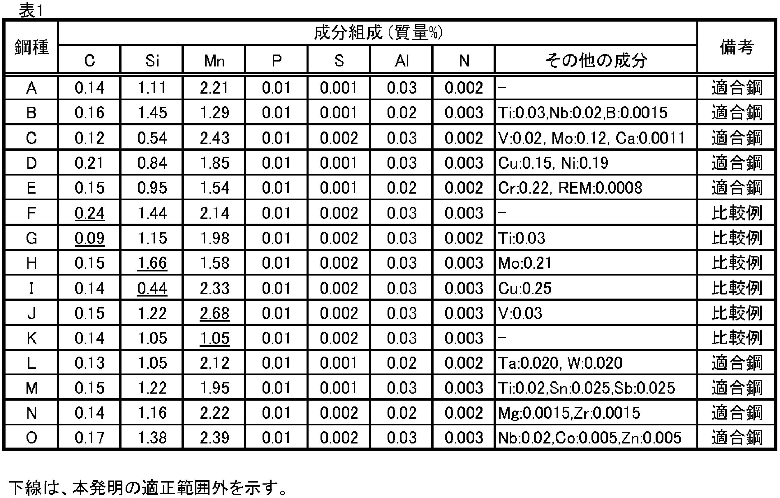
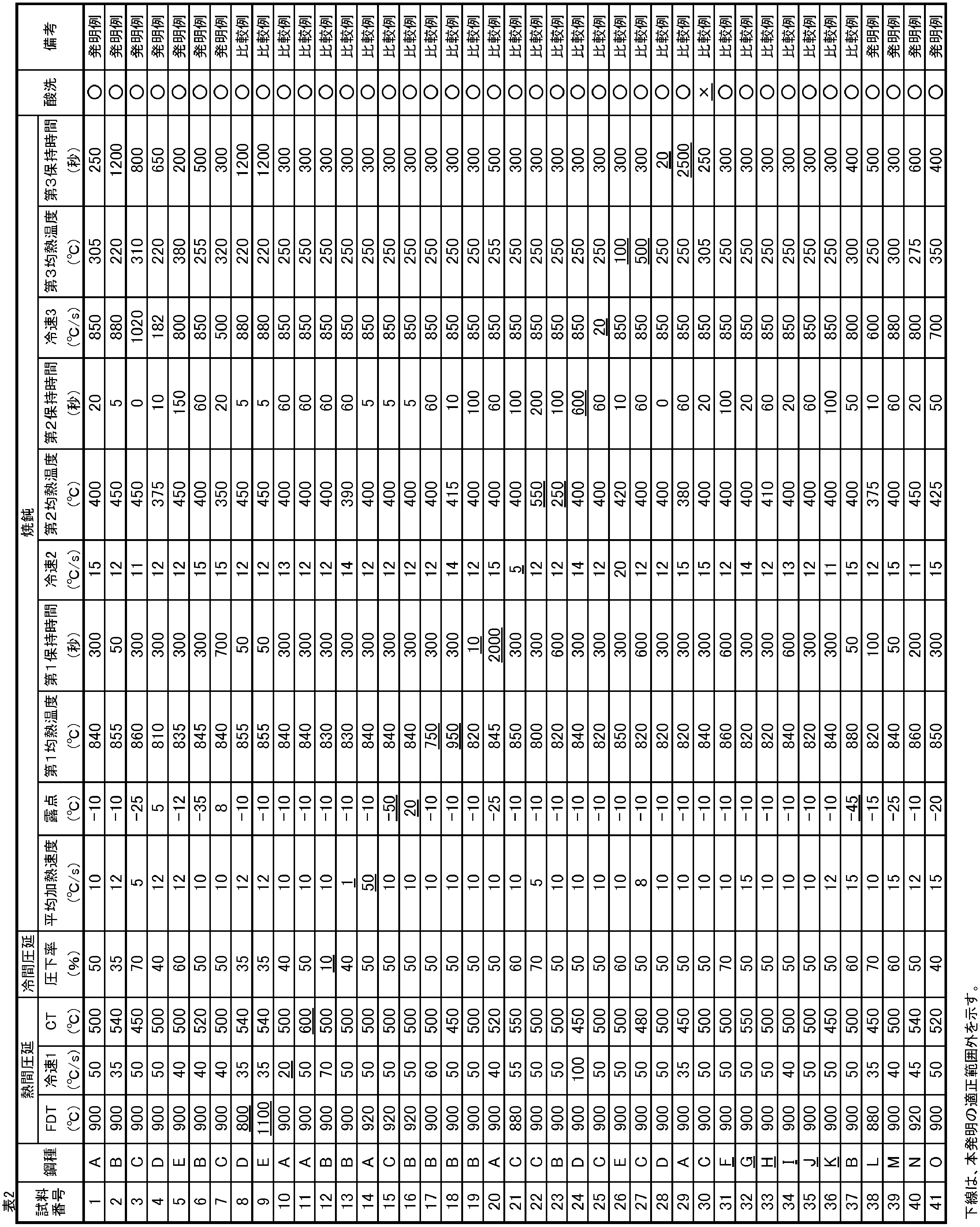
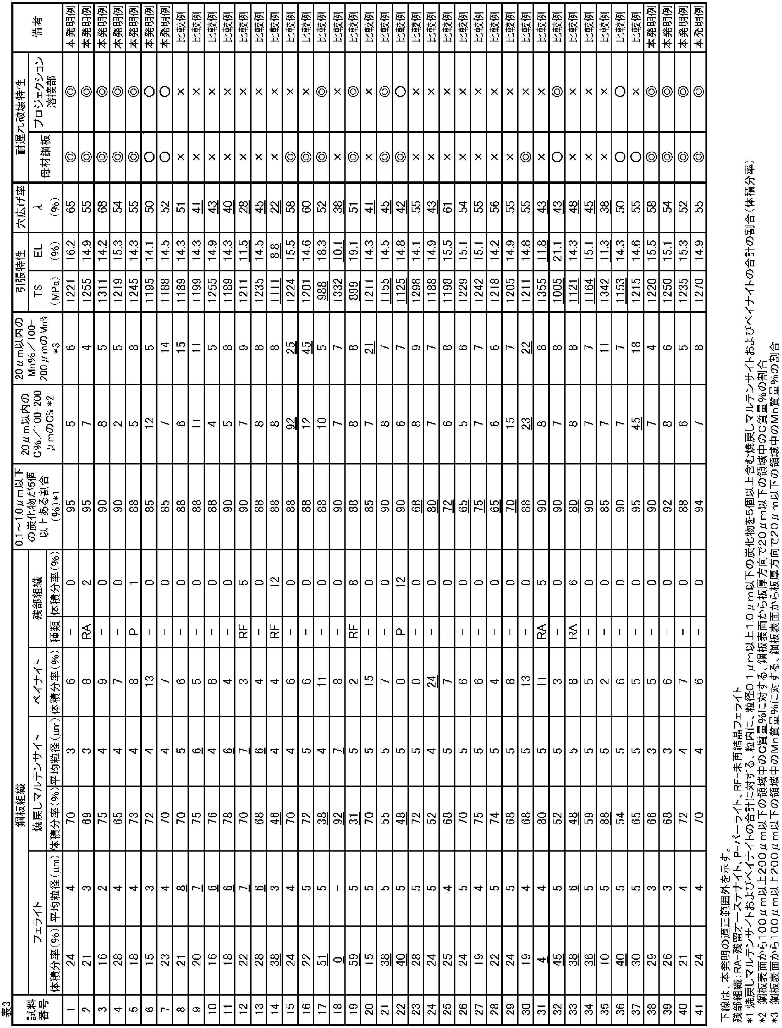
Claims (4)
- 質量%で、
C:0.10%以上0.22%以下、
Si:0.5%以上1.5%以下、
Mn:1.2%以上2.5%以下、
P:0.05%以下、
S:0.005%以下、
Al:0.01%以上0.10%以下および
N:0.010%以下を含有するとともに、残部がFeおよび不可避的不純物からなる成分組成を有し、
フェライトを体積分率で5%以上35%以下、
焼戻しマルテンサイトを体積分率で50%以上85%以下、
ベイナイトを体積分率で0%以上20%以下含む複合組織を有し、
前記フェライトの平均結晶粒径は5μm以下であり、
前記焼戻しマルテンサイトの平均結晶粒径は5μm以下であり、
前記焼戻しマルテンサイトおよび前記ベイナイトの合計に対し、粒内に、粒径0.1μm以上1.0μm以下の炭化物を5個以上含む焼戻しマルテンサイトおよびベイナイトの合計が、体積分率で85%以上であり、
かつ、鋼板表面から板厚方向で20μm以下の領域中のC質量%およびMn質量%が、鋼板表面から100μm以上200μm以下の領域中のC質量%およびMn質量%に対し、それぞれ20%以下である、高強度薄鋼板。 - 前記成分組成は、さらに、質量%で、
Ti:0.05%以下、
V:0.05%以下および
Nb:0.05%以下からなる群から選択される一種以上を含有する、請求項1に記載の高強度薄鋼板。 - 前記成分組成は、さらに、質量%で、
Mo:0.50%以下、
Cr:0.50%以下、
Cu:0.50%以下、
Ni:0.50%以下、
B:0.0030%以下、
Ca:0.0050%以下、
REM:0.0050%以下、
Ta:0.100%以下、
W:0.500%以下、
Sn:0.200%以下、
Sb:0.200%以下、
Mg:0.0050%以下、
Zr:0.1000%以下、
Co:0.020%以下および
Zn:0.020%以下
からなる群から選択される一種以上を含有する、請求項1または2に記載の高強度薄鋼板。 - 請求項1から3のいずれか1項に記載の成分組成を有する鋼スラブに、仕上げ圧延終了温度が850℃以上950℃以下の条件で熱間圧延を施して熱延板とし、
次いで、前記熱延板を、30℃/s以上の第1平均冷却速度で550℃以下の巻取温度まで冷却した後、該巻取温度で巻き取り、
次いで、前記熱延板に酸洗を施し、
次いで、酸洗後の前記熱延板に、30%以上の圧下率で冷間圧延を施して冷延板とし、
次いで、前記冷延板を、600℃以上の温度域の露点を-40℃以上10℃以下として、3℃/s以上30℃/s以下の平均加熱速度で800℃以上900℃以下の第1均熱温度まで加熱し、該第1均熱温度で30s以上800s以下保持し、
次いで、前記冷延板を、前記第1均熱温度から10℃/s以上の第2平均冷却速度で350℃以上475℃以下の第2均熱温度まで冷却し、該第2均熱温度で300s以下保持し、
次いで、前記冷延板を、100℃/s以上の第3平均冷却速度で室温まで冷却し、
次いで、前記冷延板を、200℃以上400℃以下の第3均熱温度まで再加熱し、該第3均熱温度で180s以上1800s以下保持し、
次いで、前記冷延板を酸洗する、高強度薄鋼板の製造方法。
Priority Applications (6)
| Application Number | Priority Date | Filing Date | Title |
|---|---|---|---|
| MX2022001480A MX2022001480A (es) | 2019-08-06 | 2020-07-16 | Hoja de acero delgada de alta resistencia y metodo para su fabricacion. |
| US17/632,566 US12195819B2 (en) | 2019-08-06 | 2020-07-16 | High-strength thin steel sheet and method for manufacturing same |
| KR1020227005258A KR102682666B1 (ko) | 2019-08-06 | 2020-07-16 | 고강도 박강판 및 그의 제조 방법 |
| JP2020560504A JP6874919B1 (ja) | 2019-08-06 | 2020-07-16 | 高強度薄鋼板およびその製造方法 |
| CN202080055493.2A CN114207170B (zh) | 2019-08-06 | 2020-07-16 | 高强度薄钢板及其制造方法 |
| EP20850681.6A EP4012055A4 (en) | 2019-08-06 | 2020-07-16 | HIGH STRENGTH THIN STEEL SHEET AND METHOD OF PRODUCTION THEREOF |
Applications Claiming Priority (2)
| Application Number | Priority Date | Filing Date | Title |
|---|---|---|---|
| JP2019-144678 | 2019-08-06 | ||
| JP2019144678 | 2019-08-06 |
Publications (1)
| Publication Number | Publication Date |
|---|---|
| WO2021024748A1 true WO2021024748A1 (ja) | 2021-02-11 |
Family
ID=74503517
Family Applications (1)
| Application Number | Title | Priority Date | Filing Date |
|---|---|---|---|
| PCT/JP2020/027730 Ceased WO2021024748A1 (ja) | 2019-08-06 | 2020-07-16 | 高強度薄鋼板およびその製造方法 |
Country Status (7)
| Country | Link |
|---|---|
| US (1) | US12195819B2 (ja) |
| EP (1) | EP4012055A4 (ja) |
| JP (1) | JP6874919B1 (ja) |
| KR (1) | KR102682666B1 (ja) |
| CN (1) | CN114207170B (ja) |
| MX (1) | MX2022001480A (ja) |
| WO (1) | WO2021024748A1 (ja) |
Cited By (7)
| Publication number | Priority date | Publication date | Assignee | Title |
|---|---|---|---|---|
| JPWO2022190958A1 (ja) * | 2021-03-10 | 2022-09-15 | ||
| US20230036084A1 (en) * | 2019-12-13 | 2023-02-02 | Arcelormittal | Heat treated cold rolled steel sheet and a method of manufacturing thereof |
| WO2023188643A1 (ja) * | 2022-03-31 | 2023-10-05 | Jfeスチール株式会社 | 亜鉛めっき鋼板、部材およびそれらの製造方法 |
| WO2023218731A1 (ja) * | 2022-05-11 | 2023-11-16 | Jfeスチール株式会社 | 鋼板、部材およびそれらの製造方法 |
| WO2023218730A1 (ja) * | 2022-05-11 | 2023-11-16 | Jfeスチール株式会社 | 鋼板、部材およびそれらの製造方法 |
| EP4269644A4 (en) * | 2021-03-10 | 2024-03-13 | Nippon Steel Corporation | Cold-rolled steel sheet and method for manufacturing same |
| WO2025115291A1 (ja) * | 2023-11-27 | 2025-06-05 | Jfeスチール株式会社 | 鋼板、抵抗スポット溶接方法、抵抗スポット溶接部材、および鋼板の製造方法 |
Families Citing this family (1)
| Publication number | Priority date | Publication date | Assignee | Title |
|---|---|---|---|---|
| KR20220169497A (ko) * | 2021-06-18 | 2022-12-28 | 주식회사 포스코 | 굽힘 특성이 우수한 고항복비 초고강도 강판 및 그 제조방법 |
Citations (6)
| Publication number | Priority date | Publication date | Assignee | Title |
|---|---|---|---|---|
| JPS6032173B2 (ja) | 1974-12-28 | 1985-07-26 | 富士写真フイルム株式会社 | 画像形成法 |
| JP2009203550A (ja) * | 2008-01-31 | 2009-09-10 | Jfe Steel Corp | 高強度鋼板およびその製造方法 |
| JP2009215571A (ja) * | 2008-03-07 | 2009-09-24 | Kobe Steel Ltd | 伸びフランジ性に優れた高強度冷延鋼板 |
| JP2012157900A (ja) | 2011-01-13 | 2012-08-23 | Nippon Steel Corp | プロジェクション溶接継手およびその製造方法 |
| WO2017179372A1 (ja) * | 2016-04-14 | 2017-10-19 | Jfeスチール株式会社 | 高強度鋼板およびその製造方法 |
| WO2018055695A1 (ja) * | 2016-09-21 | 2018-03-29 | 新日鐵住金株式会社 | 鋼板 |
Family Cites Families (18)
| Publication number | Priority date | Publication date | Assignee | Title |
|---|---|---|---|---|
| JPS6032173U (ja) | 1983-08-11 | 1985-03-05 | 三菱自動車工業株式会社 | 車体のフロントエンド構造 |
| BE1013359A3 (fr) * | 2000-03-22 | 2001-12-04 | Centre Rech Metallurgique | Procede pour la fabrication d'une bande en acier multiphase laminee a chaud. |
| JP4268079B2 (ja) * | 2003-03-26 | 2009-05-27 | 株式会社神戸製鋼所 | 伸び及び耐水素脆化特性に優れた超高強度鋼板、その製造方法、並びに該超高強度鋼板を用いた超高強度プレス成形部品の製造方法 |
| US8343288B2 (en) | 2008-03-07 | 2013-01-01 | Kobe Steel, Ltd. | Cold rolled steel sheet |
| JP4712882B2 (ja) * | 2008-07-11 | 2011-06-29 | 株式会社神戸製鋼所 | 耐水素脆化特性および加工性に優れた高強度冷延鋼板 |
| JP5668337B2 (ja) * | 2010-06-30 | 2015-02-12 | Jfeスチール株式会社 | 延性及び耐遅れ破壊特性に優れる超高強度冷延鋼板およびその製造方法 |
| JP5928405B2 (ja) * | 2013-05-09 | 2016-06-01 | Jfeスチール株式会社 | 耐水素誘起割れ性に優れた調質鋼板及びその製造方法 |
| JP6032173B2 (ja) | 2013-10-15 | 2016-11-24 | 新日鐵住金株式会社 | 引張最大強度980MPaを有する耐遅れ破壊特性に優れた高強度鋼板、高強度溶融亜鉛めっき鋼板、並びに、高強度合金化溶融亜鉛めっき鋼板 |
| WO2016001704A1 (en) * | 2014-07-03 | 2016-01-07 | Arcelormittal | Method for manufacturing a high strength steel sheet and sheet obtained |
| JP6044743B2 (ja) * | 2014-07-31 | 2016-12-14 | Jfeスチール株式会社 | フェライト系ステンレス鋼およびその製造方法 |
| JP6541504B2 (ja) * | 2015-03-31 | 2019-07-10 | 株式会社神戸製鋼所 | 製造安定性に優れた高強度高延性鋼板、及びその製造方法、並びに高強度高延性鋼板の製造に用いられる冷延原板 |
| MX2018007364A (es) * | 2016-03-25 | 2018-08-15 | Nippon Steel & Sumitomo Metal Corp | Lamina de acero de alta resistencia y lamina de acero galvanizada de alta resistencia. |
| MX2018011687A (es) * | 2016-03-31 | 2019-02-18 | Jfe Steel Corp | Lamina de acero y lamina de acero chapeada, metodo para la produccion de lamina de acero laminada en caliente, metodo para la produccion de lamina de acero extra-dura laminada en frio, metodo para la produccion de lamina tratada termicamente, metodo para la produccion de lamina de acero, y metodo para la produccion de lamina de acero chapeada. |
| JP6424967B2 (ja) * | 2016-05-25 | 2018-11-21 | Jfeスチール株式会社 | めっき鋼板およびその製造方法 |
| KR102206448B1 (ko) * | 2016-08-10 | 2021-01-21 | 제이에프이 스틸 가부시키가이샤 | 박강판 및 그의 제조 방법 |
| CN109642281B (zh) * | 2016-08-31 | 2021-02-23 | 杰富意钢铁株式会社 | 高强度冷轧薄钢板及其制造方法 |
| CN108977726B (zh) * | 2017-05-31 | 2020-07-28 | 宝山钢铁股份有限公司 | 一种抗延迟开裂的马氏体超高强度冷轧钢带及其制造方法 |
| US12331374B2 (en) | 2018-10-17 | 2025-06-17 | Jfe Steel Corporation | Thin steel sheet and method for manufacturing same |
-
2020
- 2020-07-16 US US17/632,566 patent/US12195819B2/en active Active
- 2020-07-16 JP JP2020560504A patent/JP6874919B1/ja active Active
- 2020-07-16 CN CN202080055493.2A patent/CN114207170B/zh active Active
- 2020-07-16 WO PCT/JP2020/027730 patent/WO2021024748A1/ja not_active Ceased
- 2020-07-16 EP EP20850681.6A patent/EP4012055A4/en active Pending
- 2020-07-16 KR KR1020227005258A patent/KR102682666B1/ko active Active
- 2020-07-16 MX MX2022001480A patent/MX2022001480A/es unknown
Patent Citations (6)
| Publication number | Priority date | Publication date | Assignee | Title |
|---|---|---|---|---|
| JPS6032173B2 (ja) | 1974-12-28 | 1985-07-26 | 富士写真フイルム株式会社 | 画像形成法 |
| JP2009203550A (ja) * | 2008-01-31 | 2009-09-10 | Jfe Steel Corp | 高強度鋼板およびその製造方法 |
| JP2009215571A (ja) * | 2008-03-07 | 2009-09-24 | Kobe Steel Ltd | 伸びフランジ性に優れた高強度冷延鋼板 |
| JP2012157900A (ja) | 2011-01-13 | 2012-08-23 | Nippon Steel Corp | プロジェクション溶接継手およびその製造方法 |
| WO2017179372A1 (ja) * | 2016-04-14 | 2017-10-19 | Jfeスチール株式会社 | 高強度鋼板およびその製造方法 |
| WO2018055695A1 (ja) * | 2016-09-21 | 2018-03-29 | 新日鐵住金株式会社 | 鋼板 |
Non-Patent Citations (1)
| Title |
|---|
| "Handbook of X-ray Diffraction", 2000, RIGAKU CORPORATION, pages: 26,62 - 64 |
Cited By (18)
| Publication number | Priority date | Publication date | Assignee | Title |
|---|---|---|---|---|
| US20230036084A1 (en) * | 2019-12-13 | 2023-02-02 | Arcelormittal | Heat treated cold rolled steel sheet and a method of manufacturing thereof |
| JPWO2022190958A1 (ja) * | 2021-03-10 | 2022-09-15 | ||
| WO2022190958A1 (ja) * | 2021-03-10 | 2022-09-15 | 日本製鉄株式会社 | 冷延鋼板及びその製造方法 |
| EP4269643A4 (en) * | 2021-03-10 | 2024-03-13 | Nippon Steel Corporation | COLD ROLLED STEEL SHEET AND PRODUCTION PROCESS THEREOF |
| EP4269644A4 (en) * | 2021-03-10 | 2024-03-13 | Nippon Steel Corporation | Cold-rolled steel sheet and method for manufacturing same |
| WO2023188643A1 (ja) * | 2022-03-31 | 2023-10-05 | Jfeスチール株式会社 | 亜鉛めっき鋼板、部材およびそれらの製造方法 |
| JPWO2023188643A1 (ja) * | 2022-03-31 | 2023-10-05 | ||
| JP7619483B2 (ja) | 2022-03-31 | 2025-01-22 | Jfeスチール株式会社 | 亜鉛めっき鋼板、部材およびそれらの製造方法 |
| JPWO2023218730A1 (ja) * | 2022-05-11 | 2023-11-16 | ||
| JPWO2023218731A1 (ja) * | 2022-05-11 | 2023-11-16 | ||
| WO2023218730A1 (ja) * | 2022-05-11 | 2023-11-16 | Jfeスチール株式会社 | 鋼板、部材およびそれらの製造方法 |
| JP7601257B2 (ja) | 2022-05-11 | 2024-12-17 | Jfeスチール株式会社 | 鋼板、部材およびそれらの製造方法 |
| JP7601256B2 (ja) | 2022-05-11 | 2024-12-17 | Jfeスチール株式会社 | 鋼板、部材およびそれらの製造方法 |
| WO2023218731A1 (ja) * | 2022-05-11 | 2023-11-16 | Jfeスチール株式会社 | 鋼板、部材およびそれらの製造方法 |
| EP4502218A4 (en) * | 2022-05-11 | 2025-07-30 | Jfe Steel Corp | STEEL SHEET, ELEMENT AND METHOD FOR THE PRODUCTION THEREOF |
| EP4502217A4 (en) * | 2022-05-11 | 2025-07-30 | Jfe Steel Corp | STEEL SHEET, ELEMENT AND METHOD FOR THE PRODUCTION THEREOF |
| WO2025115291A1 (ja) * | 2023-11-27 | 2025-06-05 | Jfeスチール株式会社 | 鋼板、抵抗スポット溶接方法、抵抗スポット溶接部材、および鋼板の製造方法 |
| JP7722606B1 (ja) * | 2023-11-27 | 2025-08-13 | Jfeスチール株式会社 | 鋼板、抵抗スポット溶接方法、抵抗スポット溶接部材、および鋼板の製造方法 |
Also Published As
| Publication number | Publication date |
|---|---|
| US12195819B2 (en) | 2025-01-14 |
| JPWO2021024748A1 (ja) | 2021-09-13 |
| CN114207170A (zh) | 2022-03-18 |
| MX2022001480A (es) | 2022-03-02 |
| CN114207170B (zh) | 2022-09-13 |
| US20220275471A1 (en) | 2022-09-01 |
| EP4012055A4 (en) | 2022-08-31 |
| EP4012055A1 (en) | 2022-06-15 |
| KR102682666B1 (ko) | 2024-07-08 |
| JP6874919B1 (ja) | 2021-05-19 |
| KR20220033519A (ko) | 2022-03-16 |
Similar Documents
| Publication | Publication Date | Title |
|---|---|---|
| JP6874919B1 (ja) | 高強度薄鋼板およびその製造方法 | |
| JP7088140B2 (ja) | 高強度薄鋼板およびその製造方法 | |
| JP7001204B1 (ja) | 鋼板及び部材 | |
| EP3467134B1 (en) | High-strength thin steel sheet and method for manufacturing same | |
| JP6787535B1 (ja) | 高強度鋼板およびその製造方法 | |
| TWI513524B (zh) | High-strength hot-dip galvanized steel sheet, high-strength alloyed hot-dip galvanized steel sheet excellent in mechanical truncation characteristics, and the like | |
| TWI418640B (zh) | High-strength hot-dip galvanized steel sheet and its manufacturing method | |
| CN109154045B (zh) | 镀覆钢板及其制造方法 | |
| WO2021019947A1 (ja) | 高強度鋼板およびその製造方法 | |
| EP2527484B1 (en) | Method for manufacturing a high-strength galvanized steel sheet having excellent formability and spot weldability | |
| JP6950826B2 (ja) | 高強度鋼板、熱延鋼板の製造方法、冷延フルハード鋼板の製造方法および高強度鋼板の製造方法 | |
| CN113272465B (zh) | 高强度冷轧钢板及其制造方法 | |
| KR20130032392A (ko) | 성형성이 우수한 고강도 용융 아연 도금 강판 및 그 제조 방법 | |
| WO2017169939A1 (ja) | 薄鋼板およびめっき鋼板、並びに、熱延鋼板の製造方法、冷延フルハード鋼板の製造方法、熱処理板の製造方法、薄鋼板の製造方法およびめっき鋼板の製造方法 | |
| WO2019003450A1 (ja) | 熱間プレス部材およびその製造方法ならびに熱間プレス用冷延鋼板 | |
| WO2020170667A1 (ja) | 熱間プレス部材、熱間プレス用冷延鋼板およびそれらの製造方法 | |
| WO2017169940A1 (ja) | 薄鋼板およびめっき鋼板、並びに、熱延鋼板の製造方法、冷延フルハード鋼板の製造方法、熱処理板の製造方法、薄鋼板の製造方法およびめっき鋼板の製造方法 | |
| EP3940091A1 (en) | Hot press member, production method for steel sheet for hot press, and production method for hot press member | |
| CN117337221A (zh) | 汽车用构件及其电阻点焊方法 | |
| JP7800780B1 (ja) | 高強度鋼板およびその製造方法 | |
| KR20260047615A (ko) | 강판, 저항 스폿 용접 방법, 저항 스폿 용접 부재, 및 강판의 제조 방법 |
Legal Events
| Date | Code | Title | Description |
|---|---|---|---|
| ENP | Entry into the national phase |
Ref document number: 2020560504 Country of ref document: JP Kind code of ref document: A |
|
| 121 | Ep: the epo has been informed by wipo that ep was designated in this application |
Ref document number: 20850681 Country of ref document: EP Kind code of ref document: A1 |
|
| WWE | Wipo information: entry into national phase |
Ref document number: MX/A/2022/001480 Country of ref document: MX |
|
| NENP | Non-entry into the national phase |
Ref country code: DE |
|
| ENP | Entry into the national phase |
Ref document number: 20227005258 Country of ref document: KR Kind code of ref document: A |
|
| ENP | Entry into the national phase |
Ref document number: 2020850681 Country of ref document: EP Effective date: 20220307 |
|
| WWG | Wipo information: grant in national office |
Ref document number: MX/A/2022/001480 Country of ref document: MX |