WO2021025105A1 - 分極転移装置、及びマイクロ流路デバイス - Google Patents
分極転移装置、及びマイクロ流路デバイス Download PDFInfo
- Publication number
- WO2021025105A1 WO2021025105A1 PCT/JP2020/030152 JP2020030152W WO2021025105A1 WO 2021025105 A1 WO2021025105 A1 WO 2021025105A1 JP 2020030152 W JP2020030152 W JP 2020030152W WO 2021025105 A1 WO2021025105 A1 WO 2021025105A1
- Authority
- WO
- WIPO (PCT)
- Prior art keywords
- precursor
- magnetic field
- microchannel
- transfer device
- polarization transfer
- Prior art date
- Legal status (The legal status is an assumption and is not a legal conclusion. Google has not performed a legal analysis and makes no representation as to the accuracy of the status listed.)
- Ceased
Links
Images


Classifications
-
- G—PHYSICS
- G01—MEASURING; TESTING
- G01R—MEASURING ELECTRIC VARIABLES; MEASURING MAGNETIC VARIABLES
- G01R33/00—Arrangements or instruments for measuring magnetic variables
- G01R33/20—Arrangements or instruments for measuring magnetic variables involving magnetic resonance
- G01R33/28—Details of apparatus provided for in groups G01R33/44 - G01R33/64
- G01R33/30—Sample handling arrangements, e.g. sample cells, spinning mechanisms
-
- G—PHYSICS
- G01—MEASURING; TESTING
- G01R—MEASURING ELECTRIC VARIABLES; MEASURING MAGNETIC VARIABLES
- G01R33/00—Arrangements or instruments for measuring magnetic variables
- G01R33/20—Arrangements or instruments for measuring magnetic variables involving magnetic resonance
- G01R33/28—Details of apparatus provided for in groups G01R33/44 - G01R33/64
- G01R33/282—Means specially adapted for hyperpolarisation or for hyperpolarised contrast agents, e.g. for the generation of hyperpolarised gases using optical pumping cells, for storing hyperpolarised contrast agents or for the determination of the polarisation of a hyperpolarised contrast agent
-
- G—PHYSICS
- G01—MEASURING; TESTING
- G01R—MEASURING ELECTRIC VARIABLES; MEASURING MAGNETIC VARIABLES
- G01R33/00—Arrangements or instruments for measuring magnetic variables
- G01R33/20—Arrangements or instruments for measuring magnetic variables involving magnetic resonance
- G01R33/28—Details of apparatus provided for in groups G01R33/44 - G01R33/64
- G01R33/30—Sample handling arrangements, e.g. sample cells, spinning mechanisms
- G01R33/302—Miniaturized sample handling arrangements for sampling small quantities, e.g. flow-through microfluidic NMR chips
-
- G—PHYSICS
- G01—MEASURING; TESTING
- G01R—MEASURING ELECTRIC VARIABLES; MEASURING MAGNETIC VARIABLES
- G01R33/00—Arrangements or instruments for measuring magnetic variables
- G01R33/20—Arrangements or instruments for measuring magnetic variables involving magnetic resonance
- G01R33/28—Details of apparatus provided for in groups G01R33/44 - G01R33/64
- G01R33/42—Screening
-
- G—PHYSICS
- G01—MEASURING; TESTING
- G01R—MEASURING ELECTRIC VARIABLES; MEASURING MAGNETIC VARIABLES
- G01R33/00—Arrangements or instruments for measuring magnetic variables
- G01R33/20—Arrangements or instruments for measuring magnetic variables involving magnetic resonance
- G01R33/44—Arrangements or instruments for measuring magnetic variables involving magnetic resonance using nuclear magnetic resonance [NMR]
- G01R33/445—MR involving a non-standard magnetic field B0, e.g. of low magnitude as in the earth's magnetic field or in nanoTesla spectroscopy, comprising a polarizing magnetic field for pre-polarisation, B0 with a temporal variation of its magnitude or direction such as field cycling of B0 or rotation of the direction of B0, or spatially inhomogeneous B0 like in fringe-field MR or in stray-field imaging
-
- G—PHYSICS
- G01—MEASURING; TESTING
- G01R—MEASURING ELECTRIC VARIABLES; MEASURING MAGNETIC VARIABLES
- G01R33/00—Arrangements or instruments for measuring magnetic variables
- G01R33/20—Arrangements or instruments for measuring magnetic variables involving magnetic resonance
- G01R33/44—Arrangements or instruments for measuring magnetic variables involving magnetic resonance using nuclear magnetic resonance [NMR]
- G01R33/46—NMR spectroscopy
- G01R33/4608—RF excitation sequences for enhanced detection, e.g. NOE, polarisation transfer, selection of a coherence transfer pathway
-
- G—PHYSICS
- G01—MEASURING; TESTING
- G01R—MEASURING ELECTRIC VARIABLES; MEASURING MAGNETIC VARIABLES
- G01R33/00—Arrangements or instruments for measuring magnetic variables
- G01R33/20—Arrangements or instruments for measuring magnetic variables involving magnetic resonance
- G01R33/44—Arrangements or instruments for measuring magnetic variables involving magnetic resonance using nuclear magnetic resonance [NMR]
- G01R33/48—NMR imaging systems
- G01R33/54—Signal processing systems, e.g. using pulse sequences ; Generation or control of pulse sequences; Operator console
- G01R33/56—Image enhancement or correction, e.g. subtraction or averaging techniques, e.g. improvement of signal-to-noise ratio and resolution
- G01R33/5601—Image enhancement or correction, e.g. subtraction or averaging techniques, e.g. improvement of signal-to-noise ratio and resolution involving use of a contrast agent for contrast manipulation, e.g. a paramagnetic, super-paramagnetic, ferromagnetic or hyperpolarised contrast agent
Definitions
- the present disclosure relates to a polarization transfer device and a microchannel device.
- PHIP method Parahydrogen Induced Polarization
- DNP method Dynamic Nuclear Polarization
- NMR Nuclear Magnetic Resonance
- This type of PHIP method or DNP method induces hyperpolarization of 1 H nucleus, 13 C nucleus, 15 N nucleus, etc. existing in the compound, thereby inducing 1 H nucleus, 13 C nucleus, or 15 N nucleus. It is a technology that greatly improves the sensitivity of nuclear magnetic resonance such as.
- the PHIP method can induce hyperpolarization for 13 C nuclei and 15 N nuclei at room temperature and in a short time, so that an environment of extremely low temperature (for example, minus 270 ° C.) is required and It is attracting attention as an alternative technique to the DNP method, which requires a long time (see, for example, Patent Document 1, Non-Patent Document 1, Non-Patent Document 2, and Non-Patent Document 3).
- FIG. 1 is a diagram illustrating an outline of the PHIP method.
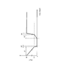
- FIG. 2 is a diagram illustrating a pattern of magnetic field fluctuation acting on a precursor in the PHIP method.
- MFC type PHIP method Magnetic Field Cycle type PHIP method
- a precursor for example, an organic compound having a carbon multiple bond
- a precursor for example, an organic compound having a carbon multiple bond
- the MFC type PHIP technique in this state, with respect to the precursor, by applying a magnetic field variation as shown in FIG. 2, the nuclear polarization occurring to 1 H nuclei from parahydrogen 13 C nuclei and 15 Polarization transition to the N nucleus.
- a substance hereinafter, also referred to as “hyperpolarized substance” in which the label of the 13 C nucleus or the 15 N nucleus is hyperpolarized.
- the pattern of magnetic field fluctuation shown in FIG. 2 shows that the strength of the magnetic field acting on the precursor (representing the strength of the magnetic flux density; the same applies hereinafter) is geomagnetic (approximately 50 ⁇ T magnetic field on the earth) at the time ⁇ 1 after mixing with parahydrogen.
- the intensity is changed from approximately 1 ⁇ T (the same applies hereinafter) to approximately 1 ⁇ T, and in the subsequent time ⁇ 2, the intensity is rapidly (that is, non-insulated) changed from approximately 1 ⁇ T to a zero magnetic field (representing the magnetic field intensity near zero T; the same applies hereinafter). Represents that.
- the magnetic field strength is gradually (that is, adiabatically) returned from the zero magnetic field to about 1 ⁇ T at the time ⁇ 3, and is rapidly returned at the time ⁇ 4 from the subsequent approximately 1 ⁇ T to the geomagnetic field.
- the pattern of magnetic field fluctuation between approximately 1 ⁇ T and approximately zero T serves as a label for the nuclear spin polarization rate of the hyperpolarized material (in the aggregate of precursors, 13 C).
- nuclear and 15 N nuclei means the degree that is polarized. a significant impact on following the same).
- the control of the magnetic field acting on the precursor is performed manually based on an empirical rule. Therefore, in the MFC type PHIP method according to the prior art, there is a problem that the nuclear spin polarization rate of the produced hyperpolarized material varies widely. In addition, since a large amount of hyperpolarized material is produced, there is also a demand for a device that enables automation of the production of hyperpolarized material.
- the inventors of the present application guide the precursor to which parahydrogen is added in the parahydrogen mixing device using a tube in a magnetic shield in which a zero magnetic field region is formed. Therefore, we tried a method to continuously generate a substance in which hyperpolarization was induced in the precursor. However, such a method faces a problem that the nuclear spin polarization rate of the hyperpolarized material cannot be sufficiently obtained.
- the present disclosure has been made in view of the above problems, and an object of the present disclosure is to provide a polarization transfer device capable of stably and continuously producing a hyperpolarized substance having a high nuclear spin polarization rate.
- a polarization transfer device that induces hyperpolarization of a precursor containing 13 C nuclei or 15 N nuclei.
- a magnetic field adjustment coil that creates a magnetic field gradient that includes a region of zero magnetic field in the space it surrounds
- a microchannel device that is arranged in the space while being connected to the parahydrogen mixing device and guides the precursor to which parahydrogen is added or mixed in the parahydrogen mixing device in the space.
- the microchannel device is The strength of the magnetic field acting on the precursor after guiding the precursor along the magnetic field gradient so that the strength of the magnetic field acting on the precursor monotonically decreases from approximately 1 ⁇ T to zero magnetic field at the first rate of change.
- Has a microchannel that guides the precursor along the magnetic field gradient so that is monotonically increasing from zero magnetic field to approximately 1 ⁇ T at the second rate of change. The first rate of change is greater than the second rate of change. It is a polarization transfer device.
- the polarization transfer apparatus According to the polarization transfer apparatus according to the present disclosure, it is possible to stably produce a hyperpolarized substance having a high nuclear spin polarization rate.
- the figure explaining the outline of the PHIP method The figure explaining the pattern of the magnetic field fluctuation acting on a precursor in a PHIP method.
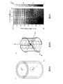
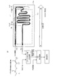
- the figure which shows an example of the whole structure of the hyperpolarized material manufacturing system which concerns on one Embodiment The figure which shows an example of the configuration of the magnetic shield (FIG. 4A), the configuration of the magnetic field adjusting coil in the magnetic shield (FIG. 4B), and the magnetic distribution in the magnetic shield (FIG. 4C) according to one embodiment.
- the figure which shows an example of the structure of the microchannel device which concerns on one Embodiment The figure which shows the change of the hydrogenation rate of a precursor by using a microchannel
- the figure which shows an example of the simulation result of the quantum statistical mechanics simulation which concerns on one Embodiment The figure which shows the magnetic field fluctuation pattern which acts on a precursor when passing through the microchannel device designed based on the simulation result of FIG.
- the temporal change of the nuclear spin polarization of 13 C nuclei when allowed to act a magnetic field variation against [1-13 C] pyruvate allyl after para hydrogenation Figure shown Diagram showing the exemplary according to Embodiment excited by polarized transfer device, 13 C-NMR spectra of hyperpolarized [1- 13 C] pyruvate measured at 1.5T MRI device Using hyperpolarized [1- 13 C] pyruvate as a metabolic probe of FIG.
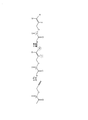
- FIG. 3 is a diagram showing an example of the overall configuration of the hyperpolarized substance manufacturing system U.
- the hyperpolarized substance manufacturing system U includes a polarization transition device 1, a precursor supply source 2, a basic solution supply source 3, a neutralization solution supply source 4, a pump 5, a parahydrogen mixing device 6, and a recovery container 7. ing.
- the polarization transition device 1 has a magnetic field fluctuation (hereinafter, abbreviated as “magnetic field fluctuation”) based on the principle of the MFC type PHIP method described above with respect to the precursor after parahydrogen addition sent from the parahydrogen mixing device 6. To induce hyperpolarization in the precursor.
- magnetic field fluctuation a magnetic field fluctuation
- the precursor supply source 2 supplies the precursor to be the target for inducing hyperpolarization to the parahydrogen mixing device 6.
- unsaturated pyruvic acid having a 13 C nucleus is used as a precursor.
- the precursor supply source 2 is, for example, a hydrogenation catalyst for inducing a parahydrogenation reaction in the precursor by containing the precursor in a solvent (here, chloroform (CHCl 3 )).
- a solvent here, chloroform (CHCl 3 )
- any unsaturated organic compound having a label of 13 C nuclei or a label of 15 N nuclei can be used as the precursor. It is desirable that the label of the 13 C nucleus or the label of the 15 N nucleus exists within the range of carbon multiple bonds to several bonds.
- Organic compounds used as precursors include, for example, fumaric acid containing carbon multiple bonds in the molecule, hydroxyethyl acrylate, pyruvate, lactic acid, ⁇ -ketoglutaric acid, amino acids, glutamine, organic acids, acyl compounds, and fatty acids.
- a vinyl alcohol having a bond, a 2-propynyl alcohol bonded by an ester bond, or the like can be used.
- 13 as the organic compound having a label C nuclei such, 12 C nuclei 13 C nuclear pyruvate-propynyl and ethyl acrylate was replaced with such a predetermined position thereof.
- 15 as the organic compound having a label of N nuclei include pyrimidine and pyridine was substituted for 14 N nuclei 15 N nucleus.
- the solvent may be alcohols such as methanol, water or the like instead of the organic solvent such as chloroform.
- the basic solution supply source 3 supplies a basic solution for hydrolyzing the precursor in which hyperpolarization has occurred to the polarization transfer device 1.
- a basic solution supplied by the basic solution source 3 for example, an aqueous solution of sodium hydroxide (NaOH) is used.
- the neutralization solution supply source 4 supplies a neutralization solution for neutralizing the solution containing the precursor in which hyperpolarization has occurred to the polarization transfer device 1.
- a neutralization solution supplied by the neutralization solution supply source 4 for example, hydrochloric acid (HCl) is used.
- the pump 5 is connected to each of the precursor supply source 2, the basic solution supply source 3, and the neutralization solution supply source 4. Then, the pump 5 constitutes a driving source for the solution delivery operation of each of the precursor supply source 2, the basic solution supply source 3, and the neutralization solution supply source 4.
- the pump 5 may use a high-pressure gas such as parahydrogen, air, nitrogen, or argon as a driving source for the solution delivery operation.
- the para-hydrogen mixing device 6 mixes the precursor supplied from the precursor supply source 2 with the para-hydrogen gas.
- the precursor, the position of the carbon multiple bonds of the precursor, parahydrogen addition reaction 1 H nuclei from parahydrogen is bound to start.
- the method by which the para-hydrogen mixing device 6 mixes the precursor and para-hydrogen may be any known method (see, for example, Patent Document 1).
- the para-hydrogen mixing apparatus 6 introduces a solution containing the precursor and a hydrogenation catalyst (for example, a rhodium-based complex) into the reaction chamber in a sprayed state, and introduces para-hydrogen at a high pressure to the precursor.
- a hydrogenation catalyst for example, a rhodium-based complex
- the para-hydrogen mixing device 6 is a polarization transfer device 1 in which a precursor to which para-hydrogen is added (or a solution in which the precursor and para-hydrogen gas are mixed) is passed through a tube or the like at a substantially constant flow velocity. Is sent out to the microchannel device 13.
- the polarization transfer device 1 includes a magnetic shield 11, a magnetic field adjusting coil 12, and a microchannel device 13.
- FIG. 4 shows an example of the configuration of the magnetic shield 11 (FIG. 4A), the configuration of the magnetic field adjusting coil 12 in the magnetic shield 11 (FIG. 4B), and the gradient magnetic field distribution created in the magnetic shield 11 (FIG. 4C). It is a figure.
- FIG. 5 is a diagram showing an example of the configuration of the microchannel device 13.
- the magnetic shield 11 magnetically shields the internal space from the outside.
- a material having a high magnetic permeability such as ⁇ metal or soft iron is used.
- the shape of the magnetic shield 11 is arbitrary, but has, for example, a substantially cylindrical shape (see FIG. 4A).
- the magnetic field adjusting coil 12 is represented by a region R0 of a magnetic field strength (zero magnetic field) near zero T in the magnetic shield 11 (in FIG. 3, a region R0 surrounded by a dotted line. Hereinafter, it is referred to as a “zero magnetic field region R0”. ) Is included in the gradient magnetic field.
- a three-axis magnetic field adjusting coil surrounding the zero magnetic field region R0 is used in each of the three directions of the X direction, the Y direction, and the Z direction in the magnetic shield 11 (FIG. 4B). See).
- the magnetic field adjusting coil 12 for example, the magnetic field distribution in the magnetic shield 11 is changed by a control device (not shown) using a 3-axis magnetic sensor (not shown) that detects the magnetic field in the magnetic shield 11. The feedback is controlled so that it does not occur.
- the zero magnetic field region R0 that can be generated by the magnetic field adjusting coil 12 is usually a local region in the center of the magnetic shield 11.
- the magnetic distribution in the magnetic shield 11 is, for example, a zero magnetic field in the substantially central region in the magnetic shield 11, and the geomagnetism from the zero magnetic field (for example, approximately 0.1 ⁇ T) as the distance from the central region to the upper side or the left and right wall sides increases. (For example, it gradually changes to about 50 ⁇ T) (see FIG. 4C).
- the slope of this gradient magnetic field can be controlled by the value of the current flowing through the magnetic field adjusting coil.
- the state of the zero magnetic field generated by the magnetic field adjusting coil 12 means a state in which the magnetic field strengths in at least the three directions of the X direction, the Y direction, and the Z direction are smaller than 150 nT, and more preferably less than 50 nT. ..
- the microchannel device 13 is arranged in the magnetic shield 11 in a state of being connected to the para-hydrogen mixing device 6, and the precursor mixed with the para-hydrogen gas in the para-hydrogen mixing device 6 is placed in the magnetic shield 11. I will guide you with.
- the microchannel device 13 has a substrate 13a, microchannels 13b and 13c formed in the substrate 13a, and input / output ports 13d to 13h formed in the substrate 13a.
- the substrate 13a is, for example, a glass substrate, a stainless steel substrate, or a resin substrate.
- the substrate 13a is typically made of a material having a magnetic permeability sufficient to be affected by a magnetic field in the magnetic shield 11.
- the input / output ports 13d to 13h include a first input port 13d, a second input port 13e, a third input port 13f, a first output port 13g, and a second output port 13h.
- the first input port 13d is connected to the para-hydrogen mixing device 6 by, for example, a tube, preferably a tube having an inner diameter of 200 ⁇ m or less, and a precursor sent from the para-hydrogen mixing device 6 is placed in the microchannel device 13. Incorporate into.
- the second input port 13e is connected to the basic solution supply source 3 by, for example, a tube, and takes in the basic solution delivered from the basic solution supply source 3 into the microchannel device 13.
- the third input port 13f is connected to the neutralization solution supply source 4 by, for example, a tube, and takes in the neutralization solution delivered from the neutralization solution supply source 4 into the microchannel device 13.
- the first output port 13g is connected to the collection container 7 by, for example, a tube, and the precursor in which hyperpolarization occurs is discharged to the outside of the microchannel device 13.
- the second output port 13h discharges, for example, an unnecessary separation liquid in which only the organic solvent is separated from the solution containing the precursor to the outside of the microchannel device 13.
- the microchannels 13b and 13c are microchannels that guide the precursor in the magnetic shield 11.
- the microchannels 13b and 13c are composed of, for example, grooves having a groove diameter of 2 mm or less and a depth of 1 mm or less, preferably a groove diameter of 500 ⁇ m or less and a depth of 250 ⁇ m or less, formed in the plane of the substrate 13a. ing.
- the groove is covered with a cover (not shown) formed on the upper surface of the substrate 13a.
- the microchannels 13b and 13c extend from the first input port 13d (here, the region near the geomagnetism), and the lead-in portion 13b that guides the precursor sent from the parahydrogen mixing device 6 to the zero magnetic field region R0.
- a lead-out portion 13c formed continuously with the pull-in portion 13b and guided to the zero magnetic field region R0 by the pull-in portion 13b to the first output port 13g (here, a region near the geomagnetism). Including.
- the precursor in the process of the precursor passing through the microchannels 13b and 13c, the precursor is subjected to a magnetic field fluctuation according to the principle of the MFC type PHIP method described above, and the precursor is subjected to the magnetic field fluctuation. It is formed to induce hyperpolarization in the body.
- the pull-in portion 13b guides the precursor within the magnetic shield 11 such that the strength of the magnetic field acting on the precursor passing through it rapidly decreases monotonically from approximately 1 ⁇ T to zero magnetic field.
- the extraction portion 13c guides the precursor in the magnetic shield 11 so that the strength of the magnetic field acting on the precursor passing through itself gradually and monotonically increases from zero magnetic field to approximately 1 ⁇ T.
- the microchannels 13b and 13c are designed according to the magnetic field distribution in the magnetic shield 11.
- the pull-in portion 13b typically guides the precursor linearly along the gradient magnetic field from a position R1 of approximately 1 ⁇ T in the magnetic shield 11 to the zero magnetic field region R0, and the pull-out portion 13c is inside the magnetic shield 11. It guides the precursor from the zero magnetic field region R0 of the above to the position R1 of about 1 ⁇ T while circumventing (that is, meandering) along the gradient magnetic field. This causes the magnetic field acting on the precursor to change rapidly (ie, adiabatically) from approximately 1 ⁇ T to zero magnetic field, and then slowly (ie, adiabatically) from zero magnetic field to approximately 1 ⁇ T. Let me.
- the region where the strength of the magnetic field acting on the precursor is between approximately 1 ⁇ T and the zero magnetic field particularly affects the nuclear spin polarization rate of the polarization transition. Since it corresponds to the polarization transition induction region L1 that gives, only the magnetic field fluctuation between the zero magnetic field and approximately 1 ⁇ T is mentioned here.
- the pull-in portion 13b guides the precursor in the magnetic shield 11 so that the strength of the magnetic field acting on the precursor passing through itself rapidly decreases monotonically from the geomagnetism to the zero magnetic field.
- the extraction portion 13c gradually and monotonically increases the intensity of the magnetic field acting on the precursor passing through itself from the zero magnetic field to about 1 ⁇ T, and rapidly and monotonically increases from the subsequent approximately 1 ⁇ T to the geomagnetism. Guide the precursor within the magnetic shield 11.
- FIG. 6 is a diagram showing changes in the hydrogenation rate of the precursor by using the microchannel.
- the hydrogenation rate of the precursor shown in FIG. 6 is when the precursor mixed or added with parahydrogen discharged from the parahydrogen mixing device 6 is guided from the geomagnetic position to the zero magnetic field position in the magnetic shield 11. Indicates the hydrogenation rate obtained by the measurement (here, the hydrogenation rate of the precursor measured in the state before the polarization transition of the precursor).
- the graph of “without microchannel” in FIG. 6 shows the hydrogenation rate of the precursor when a tube according to the prior art is used as the channel for guiding the precursor, and “using microchannel” in FIG.
- the graph in the above shows the hydrogenation rate of the precursor when the microchannel device 13 according to the present embodiment is used as the flow path for guiding the precursor.
- the parahydrogen mixing device 6 is in a state where parahydrogen is not added by guiding the precursor through the microchannels (pull-in portion 13b and extraction portion 13c). Even if the precursor is discharged from the source, the addition reaction of the mixed parahydrogen is rapidly completed in the process of passing the precursor through the drawing portion 13b. This is because the reaction time of a chemical reaction that depends on molecular diffusion is proportional to the square of the diffusion distance, and the parahydrogen addition reaction proceeds efficiently in a microchannel where the diffusion distance is several hundred ⁇ m or less. is there.
- hydrogenation reaction is complete from start of mixing parahydrogen and precursors, it is less time ( ⁇ 1 + ⁇ 2) significantly until it is guided to the zero field region R0, resulting in the 1 H nucleus to 13 C nuclei it can be before to induce polarization metastasis, suppressing the loss of polarization rate by magnetic relaxation of hyperpolarized 1 H nuclei from parahydrogen.
- the ratio of the surface area of the wall surface of the microchannel to the unit volume occupied by the precursor is remarkably high, which is caused by the solvent existing relatively around the precursor. It is considered that the magnetic relaxation that occurs is suppressed. It Thereby, 1 H nuclear polarization ratio of from parahydrogen at the stage of reaching the zero field region R0 is kept high, to induce hyperpolarization of high 13 C nuclear by polarization transfer to the subsequent 13 C nuclear Is thought to be possible.
- the solution of the precursor in which hyperpolarization occurs is immediately changed to a state suitable for a reagent for NMR spectroscopy (for example, a contrast medium or tracer for MRI diagnosis).
- the intensity of the magnetic field acting on the precursor is approximately the downstream side of the polarization transition induction region L1 in the extraction portion 13c. It is formed in a region of 1 ⁇ T or more).
- the pull-out portion 13c has a first mixing portion 13ca, a second mixing portion 13cc, and a separating portion 13cc on the downstream side of the polarization transition induction region L1. Then, the lead-out portion 13c passes the hyperpolarized precursor through the first mixing portion 13ca, the second mixing portion 13cc, and the separating portion 13cc, and then discharges the precursor to the first output port 13g.
- the first mixing unit 13ca mixes a basic solution for hydrolyzing the precursor with the solution containing the precursor in which hyperpolarization has occurred.
- the basic solution is a solution sent out from the basic solution supply source 3, and is supplied to the first mixing unit 13ca via the second input port 13e.
- the precursor in which hyperpolarization occurs is hydrolyzed in the process of being guided in the drawing section 13c. Then, in the precursor in which hyperpolarization occurs, the bond portion to which parahydrogen is added (for example, the alcohol side chain of the carboxylic acid ester to which parahydrogen is added) in the precursor is removed by hydrolysis. It changes to carboxylic acid.
- the sex solution here, sodium hydroxide
- will hydrolyze to sodium pyruvate (CH3-CO-C * O-ONa) and allyl alcohol (CH2 CH-CH2-OH).
- the viscous force is generally more dominant than the inertial force, and the liquid flow becomes a laminar flow. Therefore, the organic solvent (here, chloroform) and the aqueous solvent (here, sodium chloride) flow through the drawing portion 13c without mixing with each other, and the precursor in which hyperpolarization occurs between the two solvents Molecular transport will depend solely on molecular diffusion. That is, the precursor containing the hyperpolarization contained in the organic solvent gradually moves to the aqueous solvent while hydrolyzing at the interface between the organic solvent and the aqueous solvent.
- sodium pyruvate (CH3-CO-C * O-ONa), which is a precursor of hyperpolarization according to the present embodiment, has a hydrophilic carboxyl group, so that it can be easily placed on the aqueous solvent side. Moving.
- the second mixing unit 13cc mixes a neutralizing solution for neutralizing the solution with the solution containing the precursor in which hyperpolarization has occurred.
- the neutralizing solution is a solution sent out from the neutralizing solution supply source 4, and is supplied to the second mixing unit 13cc via the third input port 13f.
- hyperpolarized sodium pyruvate (CH3-CO-C * O-ONa) is neutralized with a neutralizing solution (here, hydrochloric acid) in the process of being guided in the drawer 13c. It will change to hyperpolarized pyruvate (CH3-CO-C * O-OH).
- the separation unit 13cc separates the organic solvent (here, chloroform) from the solution containing the precursor in which hyperpolarization occurs in the region on the downstream side of the first mixing unit 13ca.
- the precursor is in a state of being transferred from the organic solvent (here, chloroform) to the aqueous solvent (here, sodium hydroxide aqueous solution), and at this time point.
- the organic solvent is a waste liquid containing no precursor in which hyperpolarization occurs. Therefore, the microchannel device 13 separates the organic solvent from the solvent containing the precursor at the separation unit 13cc, and discharges the organic solvent to the second output port 13h.
- the hydrogenation catalyst here, rhodium-based catalyst contained in the organic solvent is difficult to be water-based, it does not diffuse from the organic solvent to the aqueous solvent, and is output together with the organic solvent. It will be discharged to the port 13h.
- the hyperpolarized substance from which impurities have been removed is discharged from the first output port 13 g, and the hyperpolarized substance is recovered in the recovery container 7. After that, it will be used as a reagent for NMR spectroscopy (for example, a contrast agent or tracer for MRI diagnosis).
- a reagent for NMR spectroscopy for example, a contrast agent or tracer for MRI diagnosis.
- the polarization transfer device 1 includes a plurality of microchannel devices 13 having the same configuration as described above, and the plurality of microchannel devices 13 generate hyperpolarization in the polarization transfer device 1. We are trying to increase the amount of polar substances produced.
- the optimum magnetic field fluctuation pattern for inducing a larger amount of polarization transition in the precursor is the chemical structure of the precursor and the chemical structure of the precursor. It depends on the position in the precursor to which parahydrogen is added.
- the microchannel device 13 be designed based on the chemical structure of the precursor and the position in the precursor to which parahydrogen is added.
- the optimum pattern of magnetic field fluctuations acting on the precursor can typically be calculated using quantum statistical mechanics simulation.
- the design parameters of the microchannel device 13 include, for example, the flow velocity of the precursor passing through the pull-in portion 13b and the pull-out portion 13c, the groove diameters of the pull-in portion 13b and the pull-out portion 13c, and the meandering mode of the pull-out portion 13c. Can be mentioned.
- the time ⁇ 1 when changing from geomagnetism to approximately 1MyuT time when changing from a substantially 1MyuT to zero field
- examples thereof include a standby time in a zero magnetic field state following ⁇ 2 and time ⁇ 2, a time ⁇ 3 when changing from zero magnetic field to approximately 1 ⁇ T, and a time ⁇ 4 when changing from approximately 1 ⁇ T to geomagnetism.
- the time width of time ⁇ 3 + ⁇ 4 (particularly, the time width ⁇ 3 from zero magnetic field to about 1 ⁇ T) is from 1 H nucleus to 13 C nucleus compared to other factors. Since the influence on the degree of polarization transition is large, it is sufficient if the time width of time ⁇ 3 + ⁇ 4 can be optimized.
- the method for determining the optimum magnetic field fluctuation pattern using quantum statistical mechanics simulation is as follows.
- Equation (1) is an expression method by the product operator method.
- the first term is the unit operator
- the second and third terms are the HH'spin operators
- the fourth term is the spin-spin interaction of each of the H- 13 C nucleus and the H'- 13 C nucleus. Represents the component spin operator.
- the equation (1) is a 2nth- order square matrix.
- the first term (the term with the frequency ⁇ H ) is the spin component of parahydrogen due to the magnetic field in the geomagnetic direction
- the second term (the term with the frequency ⁇ C ) is the geomagnetic direction.
- the third term (the term with the J coupling coefficient JAA' ) is the spin-spin interaction component between HH'
- the fourth term (the term with the J coupling coefficient JAX) is attached.
- the term) is the spin-spin interaction component between H- 13C
- the fifth term (the term with the J coupling coefficient JA'X ) is the spin-spin interaction component between H'- 13C .
- ⁇ H 1 H gyromagnetic ratio ⁇ H ⁇ magnetic field in the geomagnetic direction B / 2 ⁇
- ⁇ C 13 C nucleus
- the Hamiltonian ⁇ (see equation (2)) is applied to the density matrix ⁇ (see equation (1)), and the magnetic field fluctuation is applied to the precursor as in the following equation (3).
- Iz x represents the spin operator of the 13C nucleus.
- the expected value of the nuclear spin polarization of the 13C nucleus is calculated for various magnetic field fluctuation patterns. Then, the magnetic field fluctuation pattern that maximizes the expected value of the nuclear spin polarization of the 13C nucleus is selected as the optimum magnetic field fluctuation pattern.
- FIG. 7 is a diagram showing an example of simulation results of the quantum statistical mechanics simulation according to the present embodiment.
- Each of the graphs La to Ld in FIG. 7 shows the temporal change of the nuclear spin polarization rate of the 13 C nucleus in the precursor calculated by the above equation (3) for each of the plurality of magnetic field fluctuation patterns acting on the precursor.
- the horizontal axis represents the elapsed time [msec] from the timing at which the increase in magnetic field strength starts from the zero magnetic field in the magnetic field fluctuation pattern.
- Each graph La to Ld in FIG. 7 shows the time width of the time ⁇ 3 + ⁇ 4 (that is, the magnetic field acting on the precursor) when changing from zero magnetic field to geomagnetism among the magnetic field fluctuation patterns acting on the precursor, as shown below. Only the rate of change in intensity) is different.
- Graph La (dashed line): The time width of time ⁇ 3 + ⁇ 4 is approximately 500 msec.
- Graph Lb (dashed line): The time width of time ⁇ 3 + ⁇ 4 is approximately 1500 msec.
- Graph Ld (dotted line): The time width of time ⁇ 3 + ⁇ 4 is approximately 5000 msec.
- the microchannel device 13 is designed so that the magnetic field fluctuation pattern of the graph Lc (solid line, time width of time ⁇ 3 + ⁇ 4: approximately 4000 msec) acts on the precursor in the process of flowing through the extraction portion 13c.
- FIG. 8 is a diagram showing a magnetic field fluctuation pattern acting on the precursor when passing through the microchannel device 13 designed based on the simulation result of FIG. 7.
- the horizontal axis of FIG. 8 represents the flow time [msec] of the precursor from the timing when the precursor reaches the first input port 13d of the microchannel device 13 as a start.
- the vertical axis of FIG. 8 represents the intensity [ ⁇ T] of the magnetic field acting on the precursor at the relevant timing.
- the negative magnetic field strength on the vertical axis of FIG. 8 represents a state in which the direction of the magnetic field is reversed.
- the groove diameters of the pull-in portion 13b and the pull-out portion 13c, and the meandering mode of the pull-out portion 13c may be designed.
- FIG. 5 shows a microchannel device 13 designed to receive this magnetic field fluctuation pattern.
- the nuclear spin polarization of 13 C nuclei when allowed to act a magnetic field variation against [1-13 C] pyruvate allyl after para hydrogenation It is a figure which shows the temporal change of.
- the temporal change in the nuclear spin polarization rate of the 13C nucleus shown in FIG. 9 was calculated by quantum statistical mechanics simulation in consideration of the decay rate of the polarization rate due to magnetic relaxation.
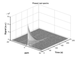
- Figure 10 is a 13 C-NMR spectra of hyperpolarized [1- 13 C] pyruvate generated by polarization transfer device 1 according to the present embodiment, a diagram showing a measurement result measured by 1.5T MRI device is there.
- Figure 11 is a diagram showing a hyperpolarized [1- 13 C] pyruvate used as a metabolic probe, 13 C-NMR spectra obtained upon observing the reaction state between tumor homogenate FIG.
- pyruvate is mainly metabolized to water and carbon dioxide by oxidative phosphorylation of mitochondria, but in cancer tissues, it is converted to lactate by suppressing pyruvate dehydrogenase and activating lactate dehydrogenase. Metabolic flux is increased.
- FIG. 12 is a diagram observing the state of hyperpolarization when fumaric acid is used as a precursor instead of pyruvic acid in the polarization transfer device 1 according to the present embodiment.
- the 13 C-NMR spectra of hyperpolarized [1- 13 C] fumarate shows a result of measurement by 1.5T MRI device. From FIG. 12, it can be seen that even when fumaric acid is used as the precursor, the polarization transfer device 1 according to the present embodiment can produce a hyperpolarized substance having a high nuclear spin polarization rate.
- the microchannel device 13 is designed by using quantum statistical mechanics simulation every time the chemical structure of the precursor substance and the position in the precursor to which parahydrogen is added are different.
- the microchannel device 13 may be designed at least according to the general tendency.
- the pull-in portion 13b is more preferably smaller than 50 ms so that, for example, the time to reduce the magnetic field strength acting on the precursor from approximately 1 ⁇ T to zero magnetic field is less than 200 ms. Designed to be. In other words, the pull-in portion 13b takes less than 200 ms, more preferably more than 50 ms, for the precursor to pass from position R1 at approximately 1 ⁇ T in the magnetic shield 11 to the zero magnetic field region R0. Designed to be smaller.
- the retracting portion 13b may be configured so that, for example, after guiding the precursor to the zero magnetic field region R0, the precursor waits in the zero magnetic field region R0 for a predetermined time (for example, about 50 milliseconds). ..
- a predetermined time for example, about 50 milliseconds.
- the waiting time in a zero magnetic field has a small effect on the nuclear spin polarization rate. Therefore, in the design of the microchannel device 13, it is arbitrary whether or not such a waiting time is provided.
- the extraction unit 13c is designed so that the time for returning the magnetic field strength acting on the precursor from the zero magnetic field to approximately 1 ⁇ T is, for example, 0.5 seconds or more and 20 seconds or less. In other words, the extraction unit 13c is designed so that the time for the precursor to pass from the zero magnetic field region R0 in the magnetic shield 11 to the position R1 of approximately 1 ⁇ T is 0.5 seconds or more and 20 seconds or less. Has been done.
- the extraction portion 13c adds the precursor substance and parahydrogen for each precursor substance (that is, the precursor substance and parahydrogen). It is desirable to be designed at a position in the precursor). For example, when the precursor is 2-propynyl pyruvate, the time to return from zero magnetic field to about 1 ⁇ T is preferably set to 4.5 seconds or more and 5.5 seconds or less. Further, for example, when the precursor is ethyl acrylate, it is desirable that the time for returning from the zero magnetic field to about 1 ⁇ T is set to 1.0 second or more and 2.0 seconds or less.
- the pull-in portion 13b zeros the precursor from the geomagnetic region.
- the entire process of the passage time when guiding the precursor to the magnetic field region R0 and the passage time when the extraction unit 13c guides the precursor from the zero magnetic field region R0 to the geomagnetic region may be optimized.
- microchannel devices 13 having different times of returning from zero magnetic field to approximately 1 ⁇ T are prepared, and micros to be used are prepared according to the precursor to be used.
- the flow path device 13 may be selected.
- the polarization transfer device 1 As described above, according to the polarization transfer device 1 according to the present embodiment, it is ideal for the precursor in the process of guiding the precursor by the microchannel device 13 without controlling the fluctuation of the magnetic field. It is possible to induce hyperpolarization in the 13 C or 15 N nuclei of the precursor by applying various magnetic field fluctuations. Further, according to the polarization transfer device 1 according to the present embodiment, it is possible to promote the addition reaction of parahydrogen to the precursor in the process of guiding the precursor by the microchannel device 13. This makes it possible to stably produce a hyperpolarized material having a high nuclear spin polarization rate.
- the polarization transfer device 1 it is possible to consistently carry out the polarization transfer process and the chemical process in the microchannel device 13. This makes it possible to shorten the time from inducing hyperpolarization in the precursor to using it as a reagent for NMR spectroscopy (for example, a contrast medium or tracer for MRI diagnosis). Since the state in which hyperpolarization occurs in the precursor lasts only for a short time (for example, about 5 minutes), from the induction of hyperpolarization in the precursor to the use as a reagent for NMR spectroscopy. The time reduction is extremely useful from a practical point of view.
- a reagent for NMR spectroscopy for example, a contrast medium or tracer for MRI diagnosis
- FIG. 13 is a diagram showing the configuration of the microchannel device 13 according to the first modification.
- the microchannel device 13 according to this modification is different from the microchannel device 13 according to the above embodiment in that it has a magnetic film 13i that adjusts the magnetic field gradient in the flow direction of the precursor.
- the magnetic field fluctuation per unit distance in the magnetic shield 11 is small, and the velocity of the magnetic field fluctuation received by the precursor in the process of flowing through the microchannel device 13 is determined by the precursor. It may not be possible to set a suitable speed to induce hyperpolarization in the body.
- the magnetic film 13i is arranged so as to adjust the magnetic field gradient in the flow direction of the precursor in the microchannel device 13 (particularly, the polarization transition induction region L1).
- the magnetic film 13i is arranged so as to cover the upper surface of the substrate 13a of the microchannel device 13, for example.
- the magnetic film 13i it is desirable that an anisotropic magnetic film that generates a magnetic field is used only in the direction along the extending direction of the lead-in portion 13b and the pull-out portion 13c (the left-right direction in FIG. 13).
- the material of the magnetic film 13i for example, an iron-based material is used.
- an isotropic magnetic film may be used.
- the magnetic field fluctuation received in the process of the precursor flowing through the microchannel device 13 is caused by inducing hyperpolarization in the precursor. It is possible to set it optimally.
- FIG. 14 is a diagram showing the configuration of the microchannel device 13 according to the second modification.
- the polarization transition process and the chemical process are separated and carried out by using the microchannel device 13 only for the process of guiding the parahydrogen mixing device 6 to the zero magnetic field region R0 and applying the magnetic field fluctuation. It is possible.
- a general device for flow synthesis can also be used for the chemical process after the polarization transition.
- the microchannel device 13 does not have the first mixing portion 13ca, the second mixing portion 13cc, and the separating portion 13cc in the drawing portion 13c, and has the polarization transition induction region L1 of the drawing portion 13c.
- the passed precursor (precursor in which hyperpolarization occurs) is discharged as it is from the first output port 13 g.
- the precursor in which this hyperpolarization occurs is sequentially sent out to the ester hydrolysis reaction vessel 8 and the neutralization reaction vessel 9 provided outside the microchannel device 13, and the ester hydrolysis reaction vessel is concerned. After the ester hydrolysis and neutralization reaction are carried out in 8 and the neutralization reaction vessel 9, it will be recovered in the recovery vessel 7.
- a resin or metal tube having an inner diameter of 500 ⁇ m or less, more preferably 200 ⁇ m or less is arranged in the magnetic shield 11 to form the microchannel device 13. May be good.
- the hyperpolarized substance generated by the polarization transfer device 1 may be directly discharged to the injector after removing impurities with an in-line filter instead of the recovery container 7. Then, the hyperpolarized substance discharged from the injector may be administered to the patient as it is. As a result, the hyperpolarized substance can be administered to the patient without being exposed to the outside air, which is also suitable in terms of hygiene.
- the polarization transfer device 1 may generate a magnetic field gradient including the zero magnetic field region R0 only by the magnetic field adjusting coil 12 without using the magnetic shield 11.
- the magnetic shield 11 When the magnetic shield 11 is used, if the magnetic field strength in the central region inside the magnetic shield 11 is set to zero by using the magnetic field adjusting coil 12, a magnetic field gradient is naturally generated from the central region of the magnetic shield 11 toward the end. can do. On the other hand, the magnetic shield 11 also has a problem that the device of the polarization transfer device 1 becomes large.
- a zero magnetic field region R0 can be created in the space surrounded by the magnetic field adjusting coil 12 without using the magnetic shield 11. It is possible to generate a magnetic field gradient that includes.
- a degaussing coil cancels the geomagnetism in the space to generate a zero magnetic field region, while an anti-Helmholtz coil creates a magnetic field gradient in the space.
- the microchannel device 13 of the present invention is not limited to such an embodiment, and by making the groove diameter of the lead-in portion 13b different from the groove diameter of the pull-out portion 13c, the flow velocity through which the precursor flows is changed on the way. You may do it. Further, also in the extraction portion 13c, the groove diameter of the polarization transition induction region L1 and the groove diameter of the region downstream of the polarization transition induction region L1 (that is, the intensity of the magnetic field acting on the precursor is approximately 1 ⁇ T or more) are made different. You may.
- the region for inducing the polarization transition with respect to the precursor and the region for carrying out the chemical process for the precursor with hyperpolarization are the same.
- the aspect formed on the substrate is shown.
- the microchannel device 13 of the present invention is not limited to such an embodiment, and includes a region that induces a polarization transition with respect to a precursor and a region that carries out a chemical process with respect to a precursor in which hyperpolarization occurs. May be arranged three-dimensionally.
- the microchannel device 13 may be a device in which a microchannel is formed of a PEEK tube or a PTFE tube having an inner diameter of 500 um or less.
- a microchannel is formed of a PEEK tube or a PTFE tube having an inner diameter of 500 um or less.
- the intensity profile of the magnetic field acting on the precursor has been optimized. It becomes difficult to adopt a flow path structure or a flow path structure in which the polarization transition process and the chemical process are consistently carried out.
- the microchannel of the microchannel device 13 is preferably formed on the substrate 13 as shown in FIG.
- the microchannel device 13 in the present invention may be used only for applying a magnetic field fluctuation pattern between approximately 1 ⁇ T and a zero magnetic field on the precursor.
- the precursor delivered from the para-hydrogen mixing device 6 may be guided by a hose from the outside of the magnetic shield 11 to the position R1 of about 1 ⁇ T inside the magnetic shield 11.
- the precursor guided from the zero magnetic field to the position R1 of about 1 ⁇ T in the magnetic shield 11 by the microchannel device 13 is pulled out of the magnetic shield 11 by a hose from the position R1 of about 1 ⁇ T in the magnetic shield 11. It may be.
- the polarization transfer apparatus According to the polarization transfer apparatus according to the present disclosure, it is possible to stably produce a hyperpolarized substance having a high nuclear spin polarization rate.
Landscapes
- Physics & Mathematics (AREA)
- Condensed Matter Physics & Semiconductors (AREA)
- General Physics & Mathematics (AREA)
- Spectroscopy & Molecular Physics (AREA)
- High Energy & Nuclear Physics (AREA)
- Chemical & Material Sciences (AREA)
- Dispersion Chemistry (AREA)
- Health & Medical Sciences (AREA)
- Epidemiology (AREA)
- Organic Low-Molecular-Weight Compounds And Preparation Thereof (AREA)
- Physical Or Chemical Processes And Apparatus (AREA)
- Magnetic Resonance Imaging Apparatus (AREA)
Abstract
Description
13C核又は15N核を含有する前駆体に対して超偏極を誘起する分極転移装置であって、
自身が囲繞する空間内に、ゼロ磁場の領域を含む磁場勾配を生成する磁場調節コイルと、
パラ水素混合装置と接続された状態で前記空間内に配設され、前記パラ水素混合装置にてパラ水素が付加又は混合された前記前駆体を前記空間内で案内するマイクロ流路デバイスと、
を備え、
前記マイクロ流路デバイスは、
前記前駆体に作用する磁界の強度が第1変化速度で略1μTからゼロ磁場まで単調減少するように、前記磁場勾配に沿って前記前駆体を案内した後、前記前駆体に作用する磁界の強度が第2変化速度でゼロ磁場から略1μTまで単調増加するように、前記磁場勾配に沿って前記前駆体を案内するマイクロ流路を有し、
前記第1変化速度は、前記第2変化速度よりも大きい、
分極転移装置である。
以下、図3を参照して、一実施形態に係る分極転移装置、及び当該分極転移装置を含む超偏極物質製造システムの全体構成について説明する。
次に、図3乃至図5を参照して、本実施形態に係る分極転移装置1の構成について、詳述する。
次に、図7~図10を参照して、分極転移装置1のマイクロ流路デバイス13の設計手法の一例について、詳述する。

グラフLa(二点鎖線):時間τ3+τ4の時間幅が略500msec
グラフLb(一点鎖線):時間τ3+τ4の時間幅が略1500msec
グラフLc(実線):時間τ3+τ4の時間幅が略4000msec
グラフLd(点線):時間τ3+τ4の時間幅が略5000msec
以上のように、本実施形態に係る分極転移装置1によれば、磁場の変動制御を行うことなく、マイクロ流路デバイス13にて前駆体を案内する過程で、当該前駆体に対して理想的な磁場変動を作用させ、前駆体の13C核又は15N核に対して超偏極を誘起することが可能である。又、本実施形態に係る分極転移装置1によれば、マイクロ流路デバイス13にて前駆体を案内する過程で、当該前駆体に対するパラ水素の付加反応を促進することが可能である。これによって、高い核スピン偏極率を有する超偏極物質を、安定的に生成することが可能である。
図13は、変形例1に係るマイクロ流路デバイス13の構成を示す図である。
図14は、変形例2に係るマイクロ流路デバイス13の構成を示す図である。
分極転移装置1で生成した超偏極物質は、回収容器7に代えて、インラインフィルターで夾雑物を除去した後、直接、インジェクタに排出されてもよい。そして、インジェクタから排出される超偏極物質を、そのまま患者に投与してもよい。これによって、超偏極物質を外気に曝すことなく、患者に投与することができるため、衛生面においても好適である。
分極転移装置1は、磁気シールド11を使用せずに、磁場調節コイル12のみでゼロ磁場領域R0を含む磁場勾配を生成してもよい。
本発明は、上記実施形態に限らず、種々に変形態様が考えられる。
1 分極転移装置
11 磁気シールド
12 磁場調節コイル
13 マイクロ流路デバイス
13a 基板
13b 引き込み部(マイクロ流路)
13c 引き出し部(マイクロ流路)
13ca 第1混合部
13cb 第2混合部
13cc 分離部
13d 第1入力ポート
13e 第2入力ポート
13f 第3入力ポート
13g 第1出力ポート
13h 第2出力ポート
13i 磁性体膜
2 前駆体供給源
3 塩基性溶液供給源
4 中和溶液供給源
5 ポンプ
6 パラ水素混合装置
7 回収容器
8 エステル加水分解反応容器
9 中和反応容器
R0 ゼロ磁場領域
R1 略1μTの位置
L1 分極転移誘導領域
Claims (19)
- 13C核又は15N核を含有する前駆体に対して超偏極を誘起する分極転移装置であって、
自身が囲繞する空間内に、ゼロ磁場の領域を含む磁場勾配を生成する磁場調節コイルと、
パラ水素混合装置と接続された状態で前記空間内に配設され、前記パラ水素混合装置にてパラ水素が付加又は混合された前記前駆体を前記空間内で案内するマイクロ流路デバイスと、
を備え、
前記マイクロ流路デバイスは、
前記前駆体に作用する磁界の強度が第1変化速度で略1μTからゼロ磁場まで単調減少するように、前記磁場勾配に沿って前記前駆体を案内した後、前記前駆体に作用する磁界の強度が第2変化速度でゼロ磁場から略1μTまで単調増加するように、前記磁場勾配に沿って前記前駆体を案内するマイクロ流路を有し、
前記第1変化速度は、前記第2変化速度よりも大きい、
分極転移装置。 - 前記マイクロ流路は、前記前駆体に作用する磁界の強度がゼロ磁場から略1μTまで単調増加するように、前記磁場勾配に沿って前記前駆体を案内した後、前記前駆体を含有する溶液に対して、前記前駆体の加水分解を行うための塩基性溶液を混合する第1混合部を有する、
請求項1に記載の分極転移装置。 - 前記マイクロ流路は、前記前駆体に作用する磁界の強度がゼロ磁場から略1μTまで単調増加するように、前記磁場勾配に沿って前記前駆体を案内した後、前記前駆体を含有する溶液に対して、当該溶液を中和するための中和溶液を混合する第2混合部を有する、
請求項2に記載の分極転移装置。 - 前記マイクロ流路は、前記第1混合部の下流側の領域において、前記前駆体を含有する溶液から有機系溶媒を分離する分離部を有する、
請求項2に記載の分極転移装置。 - 前記マイクロ流路デバイスは、前記前駆体の通流方向における磁場勾配を調整する磁性体膜を有する、
請求項1に記載の分極転移装置。 - 前記マイクロ流路の溝径は、500μm以下である、
請求項1に記載の分極転移装置。 - 前記マイクロ流路は、前記前駆体に作用する磁界の強度が前記第1変化速度で略1μTからゼロ磁場まで単調減少するように、前記空間内の略1μTの位置からゼロ磁場の位置まで直線状に前記前駆体を案内する、
請求項1に記載の分極転移装置。 - 前記マイクロ流路は、前記前駆体に作用する磁界の強度が前記第2変化速度でゼロ磁場から略1μTまで単調増加するように、前記空間内のゼロ磁場の位置から略1μTの位置まで蛇行しながら前記前駆体を案内する、
請求項1に記載の分極転移装置。 - 前記マイクロ流路において前記前駆体に作用させる磁場変動のパターンは、前記前駆体の物質及びパラ水素が付加される前記前駆体中の位置に基づいて設定される、
請求項1に記載の分極転移装置。 - 前記マイクロ流路において前記前駆体に作用させる磁場変動のパターンは、前記前駆体の物質及びパラ水素を付加する前記前駆体中の位置に基づいて、量子統計力学シミュレーションを用いて設定される、
請求項9に記載の分極転移装置。 - 前記第1変化速度は、前記前駆体に作用させる磁界強度を略1μTからゼロ磁場まで低下させる時間が、200ミリ秒よりも小さくなる速度である、
請求項1に記載の分極転移装置。 - 前記第2変化速度は、前記前駆体に作用させる磁界強度をゼロ磁場から略1μTまで上昇させる時間が、0.5秒以上で、且つ、20秒以下の速度である、
請求項1に記載の分極転移装置。 - 前記前駆体は、不飽和有機化合物である、
請求項1に記載の分極転移装置。 - 前記マイクロ流路デバイスは、13C核又は15N核が超偏極した前記前駆体を外部に送出するインジェクタに接続される、
請求項1に記載の分極転移装置。 - 前記マイクロ流路は、前記前駆体に作用する磁界の強度が地磁気からゼロ磁場まで単調減少するように、前記磁場勾配に沿って前記前駆体を案内した後、前記前駆体に作用する磁界の強度がゼロ磁場から地磁気まで単調増加するように、前記磁場勾配に沿って前記前駆体を案内する、
請求項1に記載の分極転移装置。 - 前記マイクロ流路は、前記マイクロ流路デバイスを構成する基板の面内に配設された溝により、形成されている、
請求項1に記載の分極転移装置。 - 複数の前記マイクロ流路デバイスを備える、
請求項1に記載の分極転移装置。 - 前記空間を外部から磁気的に遮蔽する磁気シールドを更に備える、
請求項1に記載の分極転移装置。 - 請求項1に記載の分極転移装置に適用されるマイクロ流路デバイス。
Priority Applications (4)
| Application Number | Priority Date | Filing Date | Title |
|---|---|---|---|
| JP2021537372A JP7311174B2 (ja) | 2019-08-06 | 2020-08-06 | 分極転移装置 |
| EP20849157.1A EP4012433A4 (en) | 2019-08-06 | 2020-08-06 | POLARIZATION TRANSFER DEVICE AND MICROFLUIDIC DEVICE |
| CN202080054539.9A CN114174849B (zh) | 2019-08-06 | 2020-08-06 | 极化转移装置及微流路器件 |
| US17/632,541 US12055606B2 (en) | 2019-08-06 | 2020-08-06 | Polarization-transfer apparatus, and microfluidic device |
Applications Claiming Priority (2)
| Application Number | Priority Date | Filing Date | Title |
|---|---|---|---|
| JP2019144537 | 2019-08-06 | ||
| JP2019-144537 | 2019-08-06 |
Publications (1)
| Publication Number | Publication Date |
|---|---|
| WO2021025105A1 true WO2021025105A1 (ja) | 2021-02-11 |
Family
ID=74503619
Family Applications (1)
| Application Number | Title | Priority Date | Filing Date |
|---|---|---|---|
| PCT/JP2020/030152 Ceased WO2021025105A1 (ja) | 2019-08-06 | 2020-08-06 | 分極転移装置、及びマイクロ流路デバイス |
Country Status (5)
| Country | Link |
|---|---|
| US (1) | US12055606B2 (ja) |
| EP (1) | EP4012433A4 (ja) |
| JP (1) | JP7311174B2 (ja) |
| CN (1) | CN114174849B (ja) |
| WO (1) | WO2021025105A1 (ja) |
Cited By (1)
| Publication number | Priority date | Publication date | Assignee | Title |
|---|---|---|---|---|
| WO2022266662A1 (en) * | 2021-06-17 | 2022-12-22 | University Of Florida Research Foundation, Inc. | Methods and systems for producing hyperpolarized fluid samples |
Families Citing this family (2)
| Publication number | Priority date | Publication date | Assignee | Title |
|---|---|---|---|---|
| US20230295058A1 (en) * | 2020-07-23 | 2023-09-21 | Nvision Imaging Technologies Gmbh | Systems and methods for generation of hyperpolarized compounds using parahydrogen |
| WO2025062996A1 (ja) * | 2023-09-22 | 2025-03-27 | 国立大学法人九州大学 | 化学誘起動的核偏極プローブ、化合物および化学誘起機能評価方法 |
Citations (7)
| Publication number | Priority date | Publication date | Assignee | Title |
|---|---|---|---|---|
| JP2007171155A (ja) * | 2005-11-25 | 2007-07-05 | Jeol Ltd | 有機合成反応装置 |
| JP2008051799A (ja) * | 2006-07-24 | 2008-03-06 | Jeol Ltd | Nmr装置およびnmr測定方法 |
| US20150217262A1 (en) | 2012-09-07 | 2015-08-06 | Cedars-Sinai Medical Center | Devices and methods for parahydrogen induced polarization |
| JP2015145853A (ja) * | 2014-02-04 | 2015-08-13 | 株式会社エム・アール・テクノロジー | 画像撮像ユニット及び画像撮像ユニットの駆動方法 |
| US20160169998A1 (en) * | 2014-10-28 | 2016-06-16 | Duke University | Method for creating hyperpolarization at microtesla magnetic fields |
| JP2016537329A (ja) * | 2013-10-28 | 2016-12-01 | ブラッコ・イメージング・ソシエタ・ペル・アチオニBracco Imaging S.P.A. | 超偏極カルボン酸塩化合物の製造方法 |
| JP2019144537A (ja) | 2018-02-19 | 2019-08-29 | 浜松ホトニクス株式会社 | データ作成装置、光制御装置、データ作成方法、及びデータ作成プログラム |
Family Cites Families (10)
| Publication number | Priority date | Publication date | Assignee | Title |
|---|---|---|---|---|
| JPS49103693A (ja) * | 1973-02-02 | 1974-10-01 | ||
| GB0219953D0 (en) * | 2002-08-29 | 2002-10-02 | Amersham Health R & D Ab | An arrangement and a method for providing contrast agents |
| JP2008008692A (ja) * | 2006-06-28 | 2008-01-17 | Jeol Ltd | マイクロチップ |
| DE102006052076A1 (de) * | 2006-11-04 | 2008-05-08 | Bruker Biospin Ag | Probenhalter für NMR-Messungen mit Feldhomogenisierung im Probenvolumen durch die Grenzflächen des Probenbehälters |
| WO2009129265A1 (en) * | 2008-04-14 | 2009-10-22 | Huntington Medical Research Institutes | Methods and apparatus for pasadena hyperpolarization |
| US8825132B2 (en) * | 2012-07-04 | 2014-09-02 | Bruker Biospin Gmbh | Field cycling method for magnetic resonance |
| CN106687808B (zh) * | 2014-07-07 | 2019-08-20 | 纳米技术分析责任有限公司 | 用于分析时变气流的便携式电子系统 |
| DE202015104743U1 (de) * | 2015-08-18 | 2015-10-22 | Aspect Imaging Ltd. | Systeme zum Einsetzen einer MRT-Hyperpolarisation eines Patienten mit einem schwachen Feld |
| CN109477872A (zh) * | 2016-03-10 | 2019-03-15 | 纪念斯隆凯特琳癌症中心 | 超极化微核磁共振系统和方法 |
| CA3033346A1 (en) * | 2016-08-09 | 2018-02-15 | Beth Israel Deaconess Medical Center, Inc. | System and method for microfluidic parahydrogen induced polarization hyperpolarizer for magnetic resonance imaging (mri) and nuclear magnetic resonance (nmr) applications |
-
2020
- 2020-08-06 EP EP20849157.1A patent/EP4012433A4/en not_active Withdrawn
- 2020-08-06 CN CN202080054539.9A patent/CN114174849B/zh active Active
- 2020-08-06 WO PCT/JP2020/030152 patent/WO2021025105A1/ja not_active Ceased
- 2020-08-06 US US17/632,541 patent/US12055606B2/en active Active
- 2020-08-06 JP JP2021537372A patent/JP7311174B2/ja active Active
Patent Citations (7)
| Publication number | Priority date | Publication date | Assignee | Title |
|---|---|---|---|---|
| JP2007171155A (ja) * | 2005-11-25 | 2007-07-05 | Jeol Ltd | 有機合成反応装置 |
| JP2008051799A (ja) * | 2006-07-24 | 2008-03-06 | Jeol Ltd | Nmr装置およびnmr測定方法 |
| US20150217262A1 (en) | 2012-09-07 | 2015-08-06 | Cedars-Sinai Medical Center | Devices and methods for parahydrogen induced polarization |
| JP2016537329A (ja) * | 2013-10-28 | 2016-12-01 | ブラッコ・イメージング・ソシエタ・ペル・アチオニBracco Imaging S.P.A. | 超偏極カルボン酸塩化合物の製造方法 |
| JP2015145853A (ja) * | 2014-02-04 | 2015-08-13 | 株式会社エム・アール・テクノロジー | 画像撮像ユニット及び画像撮像ユニットの駆動方法 |
| US20160169998A1 (en) * | 2014-10-28 | 2016-06-16 | Duke University | Method for creating hyperpolarization at microtesla magnetic fields |
| JP2019144537A (ja) | 2018-02-19 | 2019-08-29 | 浜松ホトニクス株式会社 | データ作成装置、光制御装置、データ作成方法、及びデータ作成プログラム |
Non-Patent Citations (8)
| Title |
|---|
| FRANCESCA REINERI ET AL.: "Para Hydrogen Induced Polarization of 13C carboxylate resonance in acetate and pyruvate", NATURE COMMUNICATIONS, 2015, Retrieved from the Internet <URL:https://www.nature.com/articles/ncomms6858.pdf> |
| KENSUKE TAKOSHIMA, YOSHIKI UCHIO, NEIL J. STEWART, NORIYUKI HATAE, HIROSHI HIRATA, SHINGO MATSUMOTO: "PS63 Parahydrogen induced polarization of 13C labeled pyruvate", 56TH ANNUAL MEETING OF THE SOCIETY OF ELECTRONIC SPINTRONICS (SEST); NOVEMBER 2-4, 2017, vol. 56, 2017, JP, pages 188 - 189, XP009526797 * |
| MILTON L. TRUONG ET AL.: "15N Hyperpolarization by Reversible Exchange Using SABRE-SHEATH", J. PHYS. CHEM. C, vol. 119, 2015, pages 8786 - 8797, XP055792136, Retrieved from the Internet <URL:https://www.ncbi.nlm.nih.gov/pmc/articles/PMC4419867/pdf/jp5b01799.pdf> DOI: 10.1021/acs.jpcc.5b01799 |
| NEIL J. STEWART ET AL.: "Long-range heteronuclear J-coupling constants in esters: Implications for 13C metabolic MRI by side-arm parahydrogen-induced polarization", J. MAGN. RESON., vol. 296, 2018, pages 85 - 92, XP085530527, Retrieved from the Internet <URL:https://www.sciencedirect.com/science/article/abs/pii/S1090780718302131?via%3Dihub> DOI: 10.1016/j.jmr.2018.08.009 |
| REINERI FRANCESCA, BOI TOMMASO, AIME SILVIO: "ParaHydrogen Induced Polarization of 13C carboxylate resonance in acetate and pyruvate", NATURE COMMUNICATIONS, vol. 6, no. 1, 1 May 2015 (2015-05-01), XP055792138, DOI: 10.1038/ncomms6858 * |
| See also references of EP4012433A4 |
| TRUONG MILTON L., THEIS THOMAS, COFFEY AARON M., SHCHEPIN ROMAN V., WADDELL KEVIN W., SHI FAN, GOODSON BOYD M., WARREN WARREN S., : "15 N Hyperpolarization by Reversible Exchange Using SABRE-SHEATH", THE JOURNAL OF PHYSICAL CHEMISTRY C, AMERICAN CHEMICAL SOCIETY, US, vol. 119, no. 16, 23 April 2015 (2015-04-23), US, pages 8786 - 8797, XP055792136, ISSN: 1932-7447, DOI: 10.1021/acs.jpcc.5b01799 * |
| YUKA FUKUE, YOSHITAKA UCHIO, NEIL J STEWART, HIROSHI HIRATA, SHINGO MATSUMOTO: "P88: Development of 13C Excitation Device of Magnetic Field Cycling by PHIP method", ANNUAL MEETING OF THE NUCLEAR MAGNETIC RESONANCE (NMR) SOCIETY OF JAPAN, vol. 57, 18 September 2018 (2018-09-18), JP, pages 308 - 309, XP009526798 * |
Cited By (2)
| Publication number | Priority date | Publication date | Assignee | Title |
|---|---|---|---|---|
| WO2022266662A1 (en) * | 2021-06-17 | 2022-12-22 | University Of Florida Research Foundation, Inc. | Methods and systems for producing hyperpolarized fluid samples |
| US12560663B2 (en) | 2021-06-17 | 2026-02-24 | University Of Florida Research Foundation, Inc. | Methods and systems for producing hyperpolarized fluid samples |
Also Published As
| Publication number | Publication date |
|---|---|
| CN114174849B (zh) | 2024-04-16 |
| EP4012433A1 (en) | 2022-06-15 |
| CN114174849A (zh) | 2022-03-11 |
| JPWO2021025105A1 (ja) | 2021-02-11 |
| US12055606B2 (en) | 2024-08-06 |
| JP7311174B2 (ja) | 2023-07-19 |
| US20220276327A1 (en) | 2022-09-01 |
| EP4012433A4 (en) | 2023-08-30 |
Similar Documents
| Publication | Publication Date | Title |
|---|---|---|
| JP7311174B2 (ja) | 分極転移装置 | |
| US8766633B2 (en) | Methods and apparatus for pasadena hyperpolarization | |
| Causier et al. | 3D-printed system optimizing dissolution of hyperpolarized gaseous species for micro-sized NMR | |
| JP4437280B2 (ja) | 磁気共鳴撮影用造影剤の製造方法並びに構成 | |
| JP2024524164A (ja) | 過分極した材料を生成するためのシステム及び方法 | |
| EP2904414B1 (en) | Method for hyperpolarization transfer in the liquid state | |
| WO2009090609A1 (en) | Measurement method using nuclear magnetic resonance spectroscopy and light with orbital angular momentum | |
| JP2005536306A (ja) | 磁気共鳴撮影用コントラスト剤を製造するための方法及び装置 | |
| US20120280688A1 (en) | Magnetic Resonance (MR) Radio Frequency (RF) Coil and/or High Resolution Nuclear Magnetic Resonance | |
| US9554726B2 (en) | Hyperpolarization apparatus and method for administration of a hyperpolarized liquid contrast agent | |
| CN107234238B (zh) | 一种核壳结构Au@Co(OH)2纳米微球的制备方法 | |
| JP2013519419A (ja) | 軌道角運動量を持つ光を用いる光学過分極 | |
| WO2013068448A1 (en) | Improved production of laser-polarized xenon | |
| Bussandri et al. | Radiofrequency encoded only parahydrogen spectroscopy | |
| JP2007526067A (ja) | ブースター鉄を有する磁気共鳴イメージングスキャナ | |
| Eills et al. | Metabolic reactions studied by zero-and low-field nuclear magnetic resonance | |
| EP3708533A1 (en) | Method and apparatus for in-synthesis sensing and control of magnetic nanostructures | |
| Nantogma | Instrumentation and Methods for Clinical-Scale Production of Parahydrogen-Based Hyperpolarized Contrast Agents for Molecular Imaging | |
| JP7846128B2 (ja) | パラ水素を使用する超偏極化合物の生成のためのシステム及び方法 | |
| Krummenacker | Dynamic nuclear polarization for magnetic resonance imaging. An in-bore approach | |
| Adelabu | Efficient Sabre-Sheath Hyperpolarization of Pyruvate and Other Alpha-Ketocarboxylates and Ultra-High-Quality Factor Wireless Masing Magnetic Resonance Sensing of Hyperpolarized Contrast Media | |
| Chowdhury | Clinical-Scale Hyperpolarizers for Low-Field Pulmonary MRI: Development, Optimization, and Validation | |
| Montinaro | Methods and microfabrication techniques for subnanoliter magnetic resonance spectroscopy | |
| Kamberger | Manufacturing Methods for Magnetic Resonance Microscopy Tools with Application to Neuroscience | |
| Berner | Parahydrogen hyperpolarized metabolites and spin dynamics at high magnetic field |
Legal Events
| Date | Code | Title | Description |
|---|---|---|---|
| 121 | Ep: the epo has been informed by wipo that ep was designated in this application |
Ref document number: 20849157 Country of ref document: EP Kind code of ref document: A1 |
|
| ENP | Entry into the national phase |
Ref document number: 2021537372 Country of ref document: JP Kind code of ref document: A |
|
| NENP | Non-entry into the national phase |
Ref country code: DE |
|
| ENP | Entry into the national phase |
Ref document number: 2020849157 Country of ref document: EP Effective date: 20220307 |
|
| WWW | Wipo information: withdrawn in national office |
Ref document number: 2020849157 Country of ref document: EP |