WO2021025363A2 - Dispositif de génération d'aérosol et système de génération d'aérosol le comprenant - Google Patents
Dispositif de génération d'aérosol et système de génération d'aérosol le comprenant Download PDFInfo
- Publication number
- WO2021025363A2 WO2021025363A2 PCT/KR2020/009988 KR2020009988W WO2021025363A2 WO 2021025363 A2 WO2021025363 A2 WO 2021025363A2 KR 2020009988 W KR2020009988 W KR 2020009988W WO 2021025363 A2 WO2021025363 A2 WO 2021025363A2
- Authority
- WO
- WIPO (PCT)
- Prior art keywords
- aerosol generating
- heater
- generating device
- generating article
- accommodation portion
- Prior art date
- Legal status (The legal status is an assumption and is not a legal conclusion. Google has not performed a legal analysis and makes no representation as to the accuracy of the status listed.)
- Ceased
Links
Images



Classifications
-
- A—HUMAN NECESSITIES
- A24—TOBACCO; CIGARS; CIGARETTES; SIMULATED SMOKING DEVICES; SMOKERS' REQUISITES
- A24F—SMOKERS' REQUISITES; MATCH BOXES; SIMULATED SMOKING DEVICES
- A24F40/00—Electrically operated smoking devices; Component parts thereof; Manufacture thereof; Maintenance or testing thereof; Charging means specially adapted therefor
- A24F40/40—Constructional details, e.g. connection of cartridges and battery parts
- A24F40/46—Shape or structure of electric heating means
-
- A—HUMAN NECESSITIES
- A24—TOBACCO; CIGARS; CIGARETTES; SIMULATED SMOKING DEVICES; SMOKERS' REQUISITES
- A24D—CIGARS; CIGARETTES; TOBACCO SMOKE FILTERS; MOUTHPIECES OF CIGARS OR CIGARETTES; MANUFACTURE OF TOBACCO SMOKE FILTERS OR MOUTHPIECES
- A24D1/00—Cigars; Cigarettes
- A24D1/20—Cigarettes specially adapted for simulated smoking devices
-
- A—HUMAN NECESSITIES
- A24—TOBACCO; CIGARS; CIGARETTES; SIMULATED SMOKING DEVICES; SMOKERS' REQUISITES
- A24F—SMOKERS' REQUISITES; MATCH BOXES; SIMULATED SMOKING DEVICES
- A24F40/00—Electrically operated smoking devices; Component parts thereof; Manufacture thereof; Maintenance or testing thereof; Charging means specially adapted therefor
- A24F40/10—Devices using liquid inhalable precursors
-
- A—HUMAN NECESSITIES
- A24—TOBACCO; CIGARS; CIGARETTES; SIMULATED SMOKING DEVICES; SMOKERS' REQUISITES
- A24F—SMOKERS' REQUISITES; MATCH BOXES; SIMULATED SMOKING DEVICES
- A24F40/00—Electrically operated smoking devices; Component parts thereof; Manufacture thereof; Maintenance or testing thereof; Charging means specially adapted therefor
- A24F40/20—Devices using solid inhalable precursors
-
- A—HUMAN NECESSITIES
- A24—TOBACCO; CIGARS; CIGARETTES; SIMULATED SMOKING DEVICES; SMOKERS' REQUISITES
- A24F—SMOKERS' REQUISITES; MATCH BOXES; SIMULATED SMOKING DEVICES
- A24F40/00—Electrically operated smoking devices; Component parts thereof; Manufacture thereof; Maintenance or testing thereof; Charging means specially adapted therefor
- A24F40/30—Devices using two or more structurally separated inhalable precursors, e.g. using two liquid precursors in two cartridges
-
- A—HUMAN NECESSITIES
- A24—TOBACCO; CIGARS; CIGARETTES; SIMULATED SMOKING DEVICES; SMOKERS' REQUISITES
- A24F—SMOKERS' REQUISITES; MATCH BOXES; SIMULATED SMOKING DEVICES
- A24F40/00—Electrically operated smoking devices; Component parts thereof; Manufacture thereof; Maintenance or testing thereof; Charging means specially adapted therefor
- A24F40/40—Constructional details, e.g. connection of cartridges and battery parts
-
- A—HUMAN NECESSITIES
- A24—TOBACCO; CIGARS; CIGARETTES; SIMULATED SMOKING DEVICES; SMOKERS' REQUISITES
- A24F—SMOKERS' REQUISITES; MATCH BOXES; SIMULATED SMOKING DEVICES
- A24F40/00—Electrically operated smoking devices; Component parts thereof; Manufacture thereof; Maintenance or testing thereof; Charging means specially adapted therefor
- A24F40/50—Control or monitoring
- A24F40/53—Monitoring, e.g. fault detection
-
- H—ELECTRICITY
- H05—ELECTRIC TECHNIQUES NOT OTHERWISE PROVIDED FOR
- H05B—ELECTRIC HEATING; ELECTRIC LIGHT SOURCES NOT OTHERWISE PROVIDED FOR; CIRCUIT ARRANGEMENTS FOR ELECTRIC LIGHT SOURCES, IN GENERAL
- H05B3/00—Ohmic-resistance heating
- H05B3/02—Details
- H05B3/06—Heater elements structurally combined with coupling elements or holders
Definitions
- the present disclosure relates to an aerosol generating device and an aerosol generating system including the same, and more particularly, to an aerosol generating device that may effectively heat an aerosol generating article by using a movable heater and an aerosol generating system including the same.
- An aerosol generating article accommodated in an aerosol generating device may include, for example, a liquid portion including a liquid composition and a medium portion including a tobacco material.
- the flavor and taste of an aerosol generated when the aerosol generating article is heated by the aerosol generating device may be determined by internal components of the aerosol generating article.
- the flavor and taste of the generated aerosol may be changed according to types of components that constitute the inside of the aerosol generating article, arrangement thereof, heated parts thereof, and a heating profile of the aerosol generating device.
- a plurality of separate heaters are used to provide an aerosol having an excellent flavor and taste.
- a plurality of heaters are heated to different temperatures to heat the aerosol generating article with various heating profiles.
- an aerosol generating device including a plurality of divided heaters including a plurality of divided heaters according to the related art
- all of the plurality of heaters need to be positioned inside the aerosol generating device, but an aerosol generating device has limited space.
- the consumption of energy in the aerosol generating device may be increased by the plurality of heaters.
- miniaturization of an aerosol generating device including a plurality of divided heaters according to the related art is difficult, and energy efficiency is lowered since a lot of energy is consumed from the limited capacity of the battery. This low energy efficiency requires frequent charging of the battery and thus may cause inconvenience of a user.
- an aerosol generating device including a plurality of divided heaters may have shortcomings, such as external heat generation, low internal durability, difficulty in assembly, and an increase in the cost of components, which may cause disadvantageous conditions for the manufacture and use of the aerosol generating device.
- an aerosol generating device includes an accommodation portion configured to accommodate an aerosol generating article through an opening, a heater configured to heat the accommodation portion and move along a longitudinal direction of the accommodation portion; and a heater support that supports the heater and move the heater along the longitudinal direction of the accommodation portion, wherein the heater moves between a first position corresponding to a first point of the aerosol generating article and a second position corresponding to a second point of the aerosol generating article, and wherein the first position and the second position differ according to specifications of the aerosol generating article.
- An aerosol generating device and an aerosol generating system including the same include a heater that may detect an aerosol generating article and is movable to a position corresponding to a certain point of the aerosol generating article according to the detected aerosol generating article.
- the aerosol generating article may be heated with various heating profiles without a plurality of separate heaters according to the related art.
- Various heating profiles of the aerosol generating device may effectively heat the aerosol generating article so that the flavor and taste of the generated aerosol may be improved.
- the aerosol generating device and the aerosol generating system including the same may increase energy use efficiency through effective heating. This may increase the user's convenience by reducing the charging frequency of the aerosol generating device, and the stability of the aerosol generating device and safety of a user may be improved by preventing external heat generation more effectively.
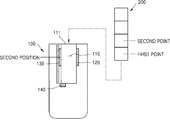
- FIG. 1A is a cross-sectional view illustrating one aspect of an aerosol generating device in which an aerosol generating article is accommodated, according to an embodiment
- FIG. 1B is a cross-sectional view illustrating another aspect of an aerosol generating device in which an aerosol generating article is accommodated, according to an embodiment
- FIG. 2A is a perspective view illustrating one aspect of a heater and a heater support of the aerosol generating device shown in FIG. 1A;
- FIG. 2B is a perspective view illustrating another aspect of a heater and a heater support of the aerosol generating device shown in FIG. 1B;
- FIG. 3 is a perspective view illustrating an aerosol generating article accommodated in an aerosol generating device according to an embodiment
- FIG. 4A is a cross-sectional view illustrating one aspect of an aerosol generating device in which the aerosol generating article shown in FIG. 3 is accommodated, according to an embodiment
- FIG. 4B is a cross-sectional view illustrating another aspect of an aerosol generating device in which the aerosol generating article shown in FIG. 3 is accommodated, according to another embodiment
- FIG. 5 is a cross-sectional view illustrating an aerosol generating device in which an aerosol generating article is accommodated, according to another embodiment
- FIG. 6 is a perspective view illustrating a heater and a heater support of the aerosol generating device shown in FIG. 5, according to another embodiment.
- FIG. 7 is a perspective view illustrating an aerosol generating system according to an embodiment.
- an aerosol generating device includes an accommodation portion configured to accommodate an aerosol generating article through an opening, a heater configured to heat the accommodation portion and move along a longitudinal direction of the accommodation portion; and a heater support that supports the heater and move the heater along the longitudinal direction of the accommodation portion, wherein the heater moves between a first position corresponding to a first point of the aerosol generating article and a second position corresponding to a second point of the aerosol generating article, and wherein the first position and the second position differ according to specifications of the aerosol generating article
- the aerosol generating device may further include a detecting sensor configured to detect the specifications of the aerosol generating article.
- the second position may be between the first position and the opening of the accommodation portion.
- the heater may surround at least part of the accommodation portion and may slide in the longitudinal direction of the accommodation portion.
- the aerosol generating device may further include a puff sensor configured to measure a duration of a single puff of a user, and the heater may move from the first position to the second position over the duration
- the heater may move from the first position to the second position over a duration of user's smoking on a single aerosol generating article.
- the heater may move from the first position to the second position over a predetermined time period.
- the aerosol generating article may include a first section in which the first point is located, and a second section in which the second point is located.
- the heater may surround at least part of the first section and at least part of the second section, when the heater is at the first position.
- the size of an area of the first section surrounded by the heater may be greater than the size of an area of the second section surrounded by the heater, when the heater is at the first position.
- the heater may surround at least part of the first section and the second section, when the heater is at the second position.
- the size of an area of the second section surrounded by the heater may be greater than the size of an area of the first section surrounded by the heater, when the heater is at the second position.
- the heater may include a plurality of heating compartments, and the plurality of heating compartments may have respective movement mechanisms.
- the movement mechanisms may include at least one of a first movement mechanism for moving from the first position to the second position, and a second movement mechanism for moving from the second position to the first position.
- the heater support may include a plurality of support members which respectively support and move the plurality of heating compartments along the longitudinal direction of the accommodation portion, and the heating compartments may be moved by the support members.
- the plurality of heating compartments may be partitioned in a circumferential direction of the heater.
- an aerosol generating system includes an aerosol generating device according to an embodiment and according to another embodiment, and an aerosol generating article accommodated in the aerosol generating device.
- the aerosol generating article may include a first section and a second section, and the first section may be a material portion including an aerosol generating material, and the second section may be a medium portion including a medium.
- a "longitudinal direction" of a component may be a direction in which the component extends along a longitudinal axis of the component (i.e., in the direction of the length of the component), as widely used in the art.
- the expression, "at least one of a, b, and c,” should be understood as including only a, only b, only c, both a and b, both a and c, both b and c, or all of a, b, and c.
- FIG. 1A is a cross-sectional view illustrating an aerosol generating device 100 in which an aerosol generating article 200 is accommodated, according to an embodiment
- FIG. 1B is a cross-sectional view illustrating the aerosol generating device 100 in which the aerosol generating article 200 is accommodated, according to another embodiment.
- one aspect of the aerosol generating device 100 shown in FIG. 1A is a cross-sectional view when a heater 120 of the aerosol generating device 100 is at a first position
- another aspect of the aerosol generating device 100 shown in FIG. 1B is a cross-sectional view when the heater 120 of the aerosol generating device 100 is at a second position.
- the aerosol generating device 100 will be described in more detail with reference to FIGS. 1A and 1B.
- the aerosol generating device 100 may include an accommodation potion 110 for accommodating an aerosol generating article 200 through an opening 111, a heater 120 that transfers heat to the accommodation portion 110 and is movable along a longitudinal direction of the accommodation portion 110, and a heater support 130 that supports the heater 120 and moves the heater 120 along the longitudinal direction of the accommodation portion 110.
- the heater 120 moves between the first position and the second position in the aerosol generating article 200.
- the arrangement of the first position and the second position may differ according to the design of the aerosol generating article 200.
- the aerosol generating device 100 may include at least one processor to control the heater support 130 to move the heater 120 or to directly control movement of the heater 120.
- the aerosol generating device 100 may include the accommodation portion 110 for accommodating the aerosol generating article 200 through the opening 111, and the heater 120 that transfers heat to the accommodation portion 110 and is movable along the longitudinal direction of the accommodation portion 110.
- the opening 111 through which the aerosol generating article 200 is inserted into the accommodation portion 110 may be formed at one end of the aerosol generating device 100 according to an embodiment, and the aerosol generating article 200 may be inserted into the accommodation portion 110 through the opening 111.
- a cavity may be formed inside the accommodation portion 110 so as to accommodate the aerosol generating article 200.
- the accommodation portion 110 may have the shape and size corresponding to the aerosol generating article 200 so as to accommodate the aerosol generating article 200.
- the accommodation portion 110 may also have a cylindrical shape cavity so as to accommodate the aerosol generating article 200.
- the shapes of the aerosol generating article 200 and the accommodation portion 110 are not limited thereto, and may be changed according to necessity.
- the aerosol generating article 200 may be inserted into the accommodation portion 110 through the opening 111 and then may be heated by the heater 120.
- the opening 111 may be aligned with the cavity inside the accommodation portion 110, and the sizes and shapes of the cross-section of the opening 111 and the cross-section of the aerosol generating article 200 may correspond to each other.
- the aerosol generating device 100 may generate aerosol by heating the aerosol generating article 200 accommodated in the accommodation portion 110, and the heater 120 for heating the aerosol generating article 200 may be arranged in the aerosol generating device 100.
- the heater 120 may transfer heat to the accommodation portion 110 and may be movable in the longitudinal direction of the accommodation portion 110.
- Components of the aerosol generating device 100 are not limited to the components shown in the drawings, and may further include other components.
- the aerosol generating device 100 may further include a battery (not shown) for supplying power to the heater 120.
- the battery may supply power to be used for the aerosol generating device 100 to operate.
- the battery may supply power for the heater 120 to be heated.
- the battery may supply power for operations of a display, a sensor, a motor, etc. of the aerosol generating device 100.
- the heater 120 may be heated by the power supplied from the battery and may transfer heat to the accommodation portion 110 so as to heat the aerosol generating article 200 inserted into the accommodation portion 110 of the aerosol generating device 100.
- the heater 120 when the aerosol generating article 200 is inserted into the accommodation portion 110 of the aerosol generating device 100, the heater 120 may be positioned close to an outer surface of the aerosol generating article 200.
- the heater 120 heated by receiving the power from the battery may increase the temperature of a material portion or a medium portion in the aerosol generating article 200.
- the heater 120 may be an electro-resistive heater.
- the heater 120 may include an electrically conductive track, and the heater 120 may be heated when currents flow through the electrically conductive track.
- the heater 120 is not limited to the example described above and may include any heaters which may be heated to a desired temperature.
- the desired temperature may be pre-set in the aerosol generating device 100 or may be set by the user.
- the heater 120 may include an induction heater.
- the heater 120 may include an electrically conductive coil for heating the aerosol generating article 200 by an induction heating method, and the aerosol generating article 200 may include a susceptor which may be hated by the induction heater 120.
- the heater 120 may include at least one from among a tube-type heating element, a plate-type heating element, a needle-type heating element, and a rod-type heating element. Also, the heater 120 may heat the inside or the outside of the aerosol generating article 200, according to the shape of the heating element.
- the heater 120 of the aerosol generating device 100 may be movable along the longitudinal direction of the accommodation portion 110, as shown in FIGS. 1A and 1B.
- the heater 120 may be movable from one end of the accommodation portion 110 to the other end of the accommodation potion 110 along the longitudinal direction of the accommodation portion 110, as shown in FIGS. 1A and 1B.
- the heater 120 may have a shape surrounding the outer surface of the accommodation portion 110. As the heater 120 moves along the longitudinal direction of the accommodation portion 110, heat transferred from the heater 120 to the accommodation portion 110 may be movable along the longitudinal direction of the accommodation portion 110 together with the heater 120.
- the aerosol generating device 100 may include the heater support 130 that supports the heater 120 and moves the heater 120 along the longitudinal direction of the accommodation portion 110.
- the heater support 130 may guide the movement of the heater 120 along the longitudinal direction of the accommodation portion 110.
- the heater 120 may be supported by the heater support 130 and may slide along the longitudinal direction of the accommodation portion 110 at predetermined speed.
- the heater 120 of the aerosol generating device 100 may be movable from the first position corresponding to the first point of the aerosol generating article 200 to the second position corresponding to the second point of the aerosol generating article 200.
- the arrangement of the first position and the second position may be changed according to the specifications of the aerosol generating article 200. Positions of the first point and the second point indicated in the drawings are just exemplary positions and may be changed.
- the heater 120 may be supported by the heater support 130 and may be movable from the first position corresponding to the first point of the aerosol generating article 200 to the second position corresponding to the second point of the aerosol generating article 200.
- the position of the heater 120 shown in FIG. 1A may be the first position corresponding to the first point of the aerosol generating article 200
- the position of the heater 120 shown in FIG. 1B may be the second position corresponding to the second point of the aerosol generating article 200.
- the first position and the second position of the heater 120 described above are not limited to those shown in the drawings, and may be changed according to embodiments.
- the first position and the second position of the heater 120 may be changed according to the specifications of the aerosol generating article 200. That is, since the first position and the second position correspond to the first point and the second point of the aerosol generating article 200, respectively, the first position and the second position may differ according to the specifications of the aerosol generating article 200 inserted into the aerosol generating device 100.
- the first point and the second point of the aerosol generating article 200 may be changed according to the types, arrangement, sizes, etc. of components of the aerosol generating article 200.
- the positions of a first point and a second point of one aerosol generating article 200 may be different from positions of a first point and a second point of another aerosol generating article 200.
- a distance between the first point and the second point of one aerosol generating article 200 may be greater than a distance between the first point and the second point of another aerosol generating article 200.
- the aerosol generating device 100 may further include a detecting sensor 140 that detects the specifications (e.g., dimensions) of the aerosol generating article 200.
- the detecting sensor 140 of the aerosol generating device 100 may be, for example, arranged adjacent to the aerosol generating article 200 inserted into the aerosol generating device 100, and may detect and recognize the specifications of the inserted aerosol generating article 200.
- the detecting sensor 140 may detect and recognize the specifications of the aerosol generating article 200.
- the heater 120 may be displaced so that the first and second positions of the heater 120 may correspond to the first and second points of the aerosol generating article 200, respectively, based on the sensing result from the detecting sensor 220.
- the detecting sensor 140 may include, for example, a pressure sensor, a hardness measurement sensor (e.g., push-pull gauge), a resistance measurement sensor, an image sensor, and/or a capacitive measurement sensor.
- the detecting sensor 140 may sense certain physical properties of the aerosol generating article 200.
- Physical properties of the aerosol generating article 200 may be pre-stored in a memory unit (not shown) of the aerosol generating device 100.
- the physical properties of the aerosol generating article 200 measured through the detecting sensor 140 may be compared with the physical properties stored in the memory unit. As such, the aerosol generating device 100 may detect and distinguish the specifications of the aerosol generating article 200.
- the second position of the heater 120 of the aerosol generating device 100 may be between the first position and the opening 111 of the accommodation portion 110. In other words, the second position of the heater 120 may be closer to the opening 111 of the accommodation portion 110 than the first position is.
- the heater 120 of the aerosol generating device 100 may move from the first position to the second position, which means that the heater 120 moves closer to the opening 111 of the accommodation portion 110.
- FIG. 2A is a perspective view of the heater 120 and the heater support 130 of the aerosol generating device 100 shown in FIG. 1A according to an embodiment.
- FIG. 2B is a perspective view of the heater 120 and the heater support 130 of the aerosol generating device 100 shown in FIG. 1B.
- the heater 120 and the heater support 130 will be described in more detail with reference to FIGS. 2A and 2B.
- the heater 120 may be supported by the heater support 130 and may move from the first position corresponding to the first point of the aerosol generating article 200 to the second position corresponding to the second point of the aerosol generating article 200.
- the position of the heater 120 shown in FIG. 2A may be the first position corresponding to the first point of the aerosol generating article 200
- the position of the heater 120 shown in FIG. 2B may be the second position corresponding to the second point of the aerosol generating article 200.
- the first position and the second position of the heater 120 described above are not limited to those shown in the drawings, and may be changed as necessary.
- the first position and the second position of the heater 120 may be changed according to the specifications of the aerosol generating article 200, as described above. Thus, a detailed description thereof in an overlapping range will be omitted.
- the heater 120 of the aerosol generating device 100 may surround at least part of the accommodation portion 110 and may slide in the longitudinal direction of the accommodation portion 110. That is, the heater 120 of the aerosol generating device 100 according to an embodiment may be an external heating-type heater that surrounds at least part of the accommodation portion 110 and transfers heat to the inside of the aerosol generating article 200.
- the heater 120 may surround at least part of the accommodation portion 110 of the aerosol generating device 100 and may slide in the longitudinal direction of the accommodation portion 110 based on electrical signals indicating the specifications of the aerosol generating article 200 which is detected by the detecting sensor 140.
- the electrical signals may be generated by a processor (not shown) electrically connected to the detecting sensor 140.
- the detecting sensor 140, the processor, and the heater 120 may be electrically connected to one another.
- the heater 120 of the aerosol generating device 100 may be supported by the heater support 130 and may slide in the longitudinal direction of the accommodation portion 110.
- the movement of the heater 120 may be performed by a mechanical mechanism.
- the mechanical mechanism may include a spring structure formed on the heater support 130, for example.
- the mechanical mechanism may include a plate spring structure formed on the heater support 130, for example.
- the plate spring formed on the heater support 130 may be released from a compressed state and when the user smokes.
- the heater 120 may slide in the longitudinal direction of the accommodation portion 110.
- the movement speed of the heater 120 may be adjusted by adjusting the release speed of the plate spring.
- the heater 120 may be set to move at a certain time when the aerosol generating article 200 is used.
- the movement of the heater 120 may be performed by an electronic mechanism.
- the electronic mechanism may include a motor installed in the heater support 130, for example.
- the motor may operate to move the heater 120. As the motor rotates, the heater 120 connected to the motor may slide in the longitudinal direction of the accommodation portion 110. In this case, the rotation speed of the motor may be adjusted so that the movement speed of the heater 120 may be adjusted.
- the motor formed in the heater support 130 may include a coil motor, a piezo motor, and/or a servo motor, for example.
- the heater 120 may move from the first position to the second position during a single puff by the user.
- the aerosol generating device 100 may include a puff sensor that measures the duration of a single puff by the user.
- the heater 120 of the aerosol generating device 100 may move from the first position to the second position over the measured duration of a single puff by the user. The movement of the heater 120 may be repeatedly performed during the user's smoking time.
- the heater 120 may return to the first position after the user's puff ends. That is, the heater 120 may repeatedly move between the first position and the second position, and may transfer heat to the aerosol generating article 200 accommodated in the accommodation portion 110. Thus, aerosol may be generated in the aerosol generating device 100.
- the heater 120 may move from the first position to the second position over the duration of smoking on a single aerosol generating article 200 by the user.
- the duration of smoking may be a time period from the beginning to the end of smoking on a single aerosol generating article 200.
- the aerosol generating device 100 may repeatedly measure the duration of user's smoking on a single aerosol generating article 200, and set or update the duration of smoking on one aerosol generating article 200 accordingly through an internal processor.
- the heater 120 may move from the first position to the second position over the duration of smoking on one set aerosol generating article 200.
- the heater 120 may be located at the first position when the user starts smoking. When the user's smoking is finished, the heater 120 may be located at the second position.
- the plate spring of the heater support 130 may be released according to the trigger signal of the aerosol generating article 200.
- the plate spring having a certain tensile force may be released over the duration of smoking on a single aerosol generating article 200 by the user, i.e., a time period from the beginning to the end of smoking on one aerosol generating article 200.
- the heater 120 of the aerosol generating device 100 may move from the first position to the second position over the duration of smoking on one aerosol generating article 200 by the user.
- the heater 120 may move from the first position to the second position at a certain speed, which may be adjusted by adjusting the release speed of the plate spring.
- the motor when the heater 120 moves using the electrical mechanism of the heater support 130, the motor may be set to rotate over the duration of smoking of one aerosol generating article 200 by the user.
- the heater 120 may move in the longitudinal direction of the accommodation portion 110 at a speed corresponding to the rotation speed of the motor, and the movement speed of the heater 120 may be changed by adjusting the rotation speed of the motor.
- the heater 120 may move from the first position to the second position over a predetermined time period.
- the predetermined time period may be appropriately determined to optimize the flavor and taste of the generated aerosol.
- the predetermined time may be automatically changed according to the specifications of the aerosol generating article 200.
- the heater 120 may move from the first position to the second position over the predetermined time period. This time period may differ according to the specifications of the aerosol generating article 200.
- FIG. 3 is a perspective view of the aerosol generating article 200 accommodated in the aerosol generating article 100 according to an embodiment.
- the aerosol generating article 200 accommodated in the aerosol generating device 100 may include a plurality of sections.
- the aerosol generating article 200 may include the first section 210, the second section 220, a third section 230, and a fourth section 240.
- the aerosol generating article 200 accommodated in the aerosol generating device 100 may include a first section 210 and a second section 220.
- the first point may be at the first section 210 of the aerosol generating article 200, and the second point may be at the second section 220.
- the first section 210 of the aerosol generating article 200 may be a material portion including an aerosol generating material.
- the aerosol generating material included in the first section 210 may be at least one from among glycerin, propylene glycol, ethylene glycol, dipropylene glycol, diethylene glycol, triethylene glycol, tetraethylene glycol, and oleyl alcohol, but is not limited thereto.
- the second section 220 of the aerosol generating article 200 may be a medium portion including a medium.
- the medium portion may be tobacco including nicotine.
- the second section 220 may include other additives, such as flavors, a wetting agent, and/or organic acid.
- the second section 220 may include a flavoring liquid, such as menthol or a moisturizer.
- the second section 220 may be manufactured in various forms.
- the second section 220 may be formed using a sheet or strands, for example. Also, the second section 220 may be formed using tiny tobacco bits which are cut from a tobacco sheet.
- the third section 230 of the aerosol generating article 200 may be a cooling portion.
- the third section 230 may generate an aerosol cooling effect.
- the user may inhale the aerosol cooled to a suitable temperature.
- the third section 230 may be formed of cellulose acetate and may be a tube-shaped structure including a hollow inside.
- the third section 230 may be manufactured by adding a plasticizer (e.g., triacetin) to a cellulose acetate tow.
- the third section 230 may be formed of paper and may have a tube-shaped structure including a hollow inside.
- the fourth section 240 of the aerosol generating article 200 may be a filter portion.
- the fourth section 240 may be manufactured by adding a plasticizer (e.g., triacetin) to an acetate tow.
- the fourth section 240 may also be manufactured to generate a flavor.
- a flavoring liquid may be injected onto the fourth section 240, or an additional fiber coated with a flavoring liquid may be inserted into the inside of the fourth section 240.
- the fourth section 240 may include at least one capsule.
- the capsule may generate a flavor or an aerosol.
- the capsule may have a configuration in which a liquid containing a flavoring material is wrapped with a film.
- the capsule may have a spherical or cylindrical shape, but is not limited thereto.
- FIG. 4A is a cross-sectional view illustrating one aspect of the aerosol generating device 100 in which the aerosol generating article 200 shown in FIG. 3 is accommodated, according to an embodiment.
- FIG. 4B is a cross-sectional view illustrating another aspect of the aerosol generating device 100 in which the aerosol generating article 200 shown in FIG. 3 is accommodated, according to another embodiment. Referring to FIGS. 4A and 4B, when the aerosol generating article 200 is inserted into the aerosol generating device 100, the position of the heater 120 corresponding to each section of the aerosol generating article 200 will be described in more detail.
- the heater 120 when the heater 120 is at the first position, the heater 120 may surround, fully or partially, the first section 210 and the second section 220. That is, the heater 120 at the first position may be in contact with the first section 210 and the second section 220. When the heater 120 is at the first position, the size of an area of the first section 210 surrounded by the heater 120 may be greater than the size of an area of the second section 220 surrounded by the heater 120.
- the heater 120 when the heater 120 is at the second position, the heater 120 may surround, fully or partially, the first section 210 and the second section 220. That is, the heater 120 at the second position may be in contact with the first section 210 and the second section 220.
- the size of an area of the second section 220 surrounded by the heater 120 may be greater than the size of an area of the first section 210 surrounded by the heater 120.
- the heater 120 may be in contact with all of the first section 210 and the second section 220, while moving from the first position to the second position.
- a plurality of sections of the aerosol generating article 200 may be heated with various heating profiles without a plurality of separate heaters.
- FIG. 5 is a cross-sectional view illustrating an aerosol generating device 100 in which an aerosol generating article 200 is accommodated, according to another embodiment.
- FIG. 6 is a perspective view illustrating a heater 120 and a heater support 130 of the aerosol generating device 100 shown in FIG. 5, according to another embodiment.
- the aerosol generating device 100 according to another embodiment will be described in more detail with reference to FIGS. 5 and 6.
- the heater 120 of the aerosol generating device 100 may include a plurality of heating compartments 120a and 120b, and the plurality of heating compartments 120a and 120b may have respective movement mechanisms.
- the movement mechanism may include at least one of first movement from the first position to the second position and second movement from the second position to the first position.
- the heater 120 may include a plurality of heating compartments 120a and 120b.
- the number of the plurality of heating compartments 120a and 120b may be two, for example, as shown in FIGS. 5 and 6.
- the plurality of heating compartments 120a and 120b may have respective movement mechanisms.
- the respective movement mechanisms may be different from each other.
- the first heating compartment 120a may execute a first movement mechanism of moving from the first position to the second position
- the second heating compartment 120b executes a second movement mechanism of moving from the second position to the first position.
- the movement mechanisms of the plurality of heating compartments 120a and 120b may be alternately changed.
- the first heating compartment 120a may move from the first position to the second position through the first movement mechanism and then may move from the second position to the first position through the second movement mechanism.
- the second heating compartment 120b may move from the second position to the first position through the second movement mechanism and then may move from the first position to the second position through the first movement mechanism.
- the first heating compartment 120a and the second heating compartment 120b may have different movement mechanisms.
- the first heating compartment 120a and the second heating compartment 120b may heat different positions of the aerosol generating article 200.
- the plurality of heating compartments 120a and 120b may form a plurality of heating points, which may enable various flavors.
- the heater support 130 of the aerosol generating device 100 may include support members which correspond to the plurality of heating compartments, respectively.
- the heater support 130 may include two support members so as to support the heating compartments separately.
- the heater support 130 may include a first support member 130a corresponding to the first heating compartment 120a, and a second support member 130b corresponding to the second heating compartment 120b.
- the support members 130a and 130b may move the heating compartments 120a and 120b by different movement mechanisms.
- the support members 130a and 130b may move the heating compartments 120a and 120b by mechanical mechanisms or electronic mechanisms.
- the mechanisms in which the support members 130a and 130b move the heating compartments 120a and 120b are the same as the mechanism in which the heater support 130 moves the heater 120. Thus, a detailed description thereof in an overlapping range will be omitted.
- the plurality of heating compartments of the aerosol generating device 100 may be arranged in a circumferential direction of the heater 120. That is, the plurality of heating compartments may extend along the circumference of the heater 120 by a certain angle. For example, the circumference may be equally divided so that a surface area of the aerosol generating article covered by each heating compartment may have the same size.
- the size and shape of the heating compartment are not limited thereto, and may be changed as necessary.
- FIG. 7 is a perspective view illustrating an aerosol generating system according to an embodiment.
- An aerosol generating system 300 may include an aerosol generating device 100 and an aerosol generating article 200 accommodated in the aerosol generating device 100.
- the aerosol generating device 100 and the aerosol generating article 200 accommodated in the aerosol generating device 100 may have similar configurations and features described above, and thus, a detailed description thereof in an overlapping range will be omitted.
- the aerosol generating device 100 may include a heater 120 that is capable of detecting the aerosol generating article 200 and moving to a position corresponding to a certain heating point of the aerosol generating article 200.
- the moveable heater 120 may heat the aerosol generating article 200 with various heating profiles without a plurality of separate heaters. By heating the aerosol generating device 100 according to various heating profiles, the flavor and taste of the aerosol may be improved.
- the aerosol generating device 100 and the aerosol generating system 300 including the same may increase energy use efficiency through effective heating. As such, g the charging frequency of the aerosol generating device 100 may be reduced, thereby improving the user's convenience. Also, external heat generation may be effectively reduced, thereby improving stability of the aerosol generating device 100 and safety of the user.
Landscapes
- Disinfection, Sterilisation Or Deodorisation Of Air (AREA)
- Resistance Heating (AREA)
- Devices For Use In Laboratory Experiments (AREA)
Abstract
Priority Applications (4)
| Application Number | Priority Date | Filing Date | Title |
|---|---|---|---|
| JP2020573434A JP7113094B2 (ja) | 2019-08-05 | 2020-07-29 | エアロゾル生成装置及びそれを含むエアロゾル生成システム |
| US17/058,173 US11930850B2 (en) | 2019-08-05 | 2020-07-29 | Aerosol generating device with moveable heater and aerosol generating system including the same |
| CN202080003270.1A CN112672653B (zh) | 2019-08-05 | 2020-07-29 | 气溶胶生成装置和包括气溶胶生成装置的气溶胶生成系统 |
| EP20811226.8A EP3806670B1 (fr) | 2019-08-05 | 2020-07-29 | Dispositif de génération d'aérosol et système de génération d'aérosol le comprenant |
Applications Claiming Priority (2)
| Application Number | Priority Date | Filing Date | Title |
|---|---|---|---|
| KR10-2019-0094956 | 2019-08-05 | ||
| KR1020190094956A KR102337229B1 (ko) | 2019-08-05 | 2019-08-05 | 에어로졸 생성 장치 및 이를 포함하는 에어로졸 생성 시스템 |
Publications (2)
| Publication Number | Publication Date |
|---|---|
| WO2021025363A2 true WO2021025363A2 (fr) | 2021-02-11 |
| WO2021025363A3 WO2021025363A3 (fr) | 2021-04-01 |
Family
ID=74503455
Family Applications (1)
| Application Number | Title | Priority Date | Filing Date |
|---|---|---|---|
| PCT/KR2020/009988 Ceased WO2021025363A2 (fr) | 2019-08-05 | 2020-07-29 | Dispositif de génération d'aérosol et système de génération d'aérosol le comprenant |
Country Status (6)
| Country | Link |
|---|---|
| US (1) | US11930850B2 (fr) |
| EP (1) | EP3806670B1 (fr) |
| JP (1) | JP7113094B2 (fr) |
| KR (1) | KR102337229B1 (fr) |
| CN (1) | CN112672653B (fr) |
| WO (1) | WO2021025363A2 (fr) |
Cited By (9)
| Publication number | Priority date | Publication date | Assignee | Title |
|---|---|---|---|---|
| EP3817578A4 (fr) * | 2019-06-17 | 2021-12-22 | KT&G Corporation | Dispositif de génération d'aérosol et article de génération d'aérosol |
| EP4042887A1 (fr) * | 2021-02-10 | 2022-08-17 | JT International SA | Système de chauffage pour dispositif de génération d'aérosol |
| WO2022210883A1 (fr) * | 2021-03-31 | 2022-10-06 | 日本たばこ産業株式会社 | Article d'inhalation d'arôme à chauffage sans combustion et produit d'inhalation d'arôme à chauffage sans combustion |
| JPWO2022239180A1 (fr) * | 2021-05-13 | 2022-11-17 | ||
| JPWO2023275955A1 (fr) * | 2021-06-28 | 2023-01-05 | ||
| EP4271130A1 (fr) * | 2022-04-29 | 2023-11-01 | Shenzhen Smoore Technology Limited | Dispositif d'atomisation électronique et dispositif de chauffage associé |
| WO2023227789A1 (fr) * | 2022-05-27 | 2023-11-30 | Fritz Schmitt | Évaporateur pour extraire et filtrer des principes actifs à partir de matières biologiques par chauffage |
| JP2024522027A (ja) * | 2021-11-23 | 2024-06-10 | ケーティー アンド ジー コーポレイション | エアロゾル発生装置及びシステム |
| EP4449919A4 (fr) * | 2022-02-11 | 2025-06-04 | Shenzhen Smoore Technology Limited | Atomiseur et dispositif d'atomisation électronique |
Families Citing this family (12)
| Publication number | Priority date | Publication date | Assignee | Title |
|---|---|---|---|---|
| KR102337229B1 (ko) * | 2019-08-05 | 2021-12-08 | 주식회사 케이티앤지 | 에어로졸 생성 장치 및 이를 포함하는 에어로졸 생성 시스템 |
| KR102726709B1 (ko) * | 2019-08-28 | 2024-11-07 | 필립모리스 프로덕츠 에스.에이. | 축 방향으로 이동 가능한 유도 히터를 갖는 에어로졸 발생 장치 |
| KR102554954B1 (ko) * | 2021-07-21 | 2023-07-12 | 주식회사 케이티앤지 | 에어로졸 생성 장치 |
| CN114259089B (zh) * | 2021-12-28 | 2025-09-05 | 深圳麦克韦尔科技有限公司 | 电子雾化装置及加热方法、液体含量的检测方法 |
| KR102729565B1 (ko) * | 2022-01-19 | 2024-11-14 | 주식회사 케이티앤지 | 에어로졸 발생 장치 및 에어로졸 발생 시스템 |
| IL317923A (en) * | 2022-06-30 | 2025-02-01 | Philip Morris Products Sa | Spray generation system with multiple spray generating sections |
| CN115568636A (zh) * | 2022-09-29 | 2023-01-06 | 深圳麦克韦尔科技有限公司 | 雾化组件、电子雾化装置以及检测方法 |
| KR102933748B1 (ko) * | 2023-03-20 | 2026-03-05 | 주식회사 케이티앤지 | 히터를 포함하는 에어로졸 발생 장치 |
| EP4656075A1 (fr) * | 2023-03-31 | 2025-12-03 | Japan Tobacco Inc. | Dispositif de génération d'aérosol |
| WO2024235949A1 (fr) * | 2023-05-17 | 2024-11-21 | Philip Morris Products S.A. | Système de génération d'aérosol à ventilation réglable |
| WO2025214960A1 (fr) * | 2024-04-09 | 2025-10-16 | Philip Morris Products S.A. | Dispositif de génération d'aérosol pour chauffer un consommable comprenant une pluralité de parties |
| WO2025214957A1 (fr) * | 2024-04-09 | 2025-10-16 | Philip Morris Products S.A. | Dispositif de génération d'aérosol destiné à être utilisé avec un article de génération d'aérosol allongé |
Citations (1)
| Publication number | Priority date | Publication date | Assignee | Title |
|---|---|---|---|---|
| WO2019030172A1 (fr) | 2017-08-09 | 2019-02-14 | Philip Morris Products S.A. | Dispositif de génération d'aérosol comprenant un dispositif de chauffage par induction et des composants mobiles |
Family Cites Families (33)
| Publication number | Priority date | Publication date | Assignee | Title |
|---|---|---|---|---|
| US5101839A (en) | 1990-08-15 | 1992-04-07 | R. J. Reynolds Tobacco Company | Cigarette and smokable filler material therefor |
| US5060671A (en) | 1989-12-01 | 1991-10-29 | Philip Morris Incorporated | Flavor generating article |
| US5269327A (en) | 1989-12-01 | 1993-12-14 | Philip Morris Incorporated | Electrical smoking article |
| US5396911A (en) * | 1990-08-15 | 1995-03-14 | R. J. Reynolds Tobacco Company | Substrate material for smoking articles |
| US5095921A (en) | 1990-11-19 | 1992-03-17 | Philip Morris Incorporated | Flavor generating article |
| US20050172976A1 (en) * | 2002-10-31 | 2005-08-11 | Newman Deborah J. | Electrically heated cigarette including controlled-release flavoring |
| EP2201850A1 (fr) * | 2008-12-24 | 2010-06-30 | Philip Morris Products S.A. | Article incluant des informations d'identification à utiliser dans un système de fumée chauffé thermiquement |
| EP2327318A1 (fr) | 2009-11-27 | 2011-06-01 | Philip Morris Products S.A. | Système de fumage chauffé électriquement doté d'un chauffage interne ou externe |
| WO2013034456A1 (fr) * | 2011-09-06 | 2013-03-14 | British American Tobacco (Investments) Limited | Chauffage de matériau fumable |
| EP3892125A3 (fr) | 2011-09-06 | 2022-01-05 | Nicoventures Trading Limited | Chauffage de substance fumable |
| PL2753202T3 (pl) * | 2011-09-06 | 2016-11-30 | Podgrzewanie materiału przeznaczonego do palenia | |
| CN104023568B (zh) | 2011-10-25 | 2017-05-31 | 菲利普莫里斯生产公司 | 具有加热器组件的浮质生成装置 |
| UA116796C2 (uk) * | 2013-03-15 | 2018-05-10 | Філіп Морріс Продактс С.А. | Система, що генерує аерозоль, з диференціальним нагріванням |
| EP4660588A3 (fr) | 2014-03-21 | 2026-03-18 | Nicoventures Trading Limited | Appareil de chauffage de matériau à fumer et article de matériau à fumer |
| WO2017029088A1 (fr) * | 2015-08-14 | 2017-02-23 | Philip Morris Products S.A. | Dispositif à fumer actionné électriquement comprenant un système d'identification d'articles à fumer dans le dispositif |
| KR102511212B1 (ko) | 2016-05-31 | 2023-03-17 | 필립모리스 프로덕츠 에스.에이. | 관형 에어로졸 발생 물품을 검출하기 위한 수단을 갖는 전기 작동식 에어로졸 발생 시스템 |
| CN111713750B (zh) | 2016-12-16 | 2023-09-05 | 韩国烟草人参公社 | 气溶胶生成系统 |
| KR102138873B1 (ko) * | 2016-12-16 | 2020-07-29 | 주식회사 케이티앤지 | 히터를 사전예열하는 에어로졸 생성 시스템 |
| CN208192124U (zh) | 2016-12-16 | 2018-12-07 | 韩国烟草人参公社 | 气溶胶产生系统及在气溶胶产生系统中使用的保持器 |
| EP3984393A1 (fr) | 2017-04-11 | 2022-04-20 | KT&G Corporation | Dispositif de génération d'aérosol et procédé de fourniture de rétroaction adaptative par reconnaissance de bouffée |
| WO2018190603A1 (fr) * | 2017-04-11 | 2018-10-18 | 주식회사 케이티앤지 | Appareil de génération d'aérosol doté d'un dispositif de chauffage mobile |
| KR20180124739A (ko) * | 2017-05-11 | 2018-11-21 | 주식회사 케이티앤지 | 궐련의 종류별로 에어로졸 생성장치에 포함된 히터의 온도를 제어하는 방법 및 궐련의 종류별로 히터의 온도를 제어하는 에어로졸 생성장치 |
| JP6850397B2 (ja) * | 2017-08-09 | 2021-03-31 | フィリップ・モーリス・プロダクツ・ソシエテ・アノニム | モジュール式誘導ヒーターを有するエアロゾル発生装置 |
| CN110996693B (zh) | 2017-10-30 | 2023-01-24 | 韩国烟草人参公社 | 气溶胶生成装置、加热器及制作气溶胶生成装置用加热器的方法 |
| TW201928255A (zh) * | 2017-12-18 | 2019-07-16 | 瑞士商傑太日煙國際股份有限公司 | 用於蒸汽產生裝置之加熱總成 |
| US11019850B2 (en) * | 2018-02-26 | 2021-06-01 | Rai Strategic Holdings, Inc. | Heat conducting substrate for electrically heated aerosol delivery device |
| US11382356B2 (en) * | 2018-03-20 | 2022-07-12 | Rai Strategic Holdings, Inc. | Aerosol delivery device with indexing movement |
| GB201805266D0 (en) * | 2018-03-29 | 2018-05-16 | Nicoventures Trading Ltd | Apparatus for generating aerosol from an aerosolisable medium and article of aerosolisable medium |
| CN108323824A (zh) * | 2018-04-27 | 2018-07-27 | 常州市派腾电子技术服务有限公司 | 电子烟的控制方法、装置及电子烟 |
| KR102507918B1 (ko) * | 2018-05-30 | 2023-03-08 | 선전 위옌 인더스트리얼 리미티드 | 에어로졸 생성 장치 |
| KR102337229B1 (ko) * | 2019-08-05 | 2021-12-08 | 주식회사 케이티앤지 | 에어로졸 생성 장치 및 이를 포함하는 에어로졸 생성 시스템 |
| CN110447969A (zh) * | 2019-08-15 | 2019-11-15 | 深圳麦克韦尔科技有限公司 | 一种低温烟具 |
| US11607511B2 (en) * | 2020-01-08 | 2023-03-21 | Nicoventures Trading Limited | Inductively-heated substrate tablet for aerosol delivery device |
-
2019
- 2019-08-05 KR KR1020190094956A patent/KR102337229B1/ko active Active
-
2020
- 2020-07-29 CN CN202080003270.1A patent/CN112672653B/zh active Active
- 2020-07-29 JP JP2020573434A patent/JP7113094B2/ja active Active
- 2020-07-29 US US17/058,173 patent/US11930850B2/en active Active
- 2020-07-29 WO PCT/KR2020/009988 patent/WO2021025363A2/fr not_active Ceased
- 2020-07-29 EP EP20811226.8A patent/EP3806670B1/fr active Active
Patent Citations (1)
| Publication number | Priority date | Publication date | Assignee | Title |
|---|---|---|---|---|
| WO2019030172A1 (fr) | 2017-08-09 | 2019-02-14 | Philip Morris Products S.A. | Dispositif de génération d'aérosol comprenant un dispositif de chauffage par induction et des composants mobiles |
Cited By (13)
| Publication number | Priority date | Publication date | Assignee | Title |
|---|---|---|---|---|
| US11930840B2 (en) | 2019-06-17 | 2024-03-19 | Kt&G Corporation | Aerosol generating device and aerosol generating article |
| EP3817578A4 (fr) * | 2019-06-17 | 2021-12-22 | KT&G Corporation | Dispositif de génération d'aérosol et article de génération d'aérosol |
| EP4042887A1 (fr) * | 2021-02-10 | 2022-08-17 | JT International SA | Système de chauffage pour dispositif de génération d'aérosol |
| WO2022210883A1 (fr) * | 2021-03-31 | 2022-10-06 | 日本たばこ産業株式会社 | Article d'inhalation d'arôme à chauffage sans combustion et produit d'inhalation d'arôme à chauffage sans combustion |
| JPWO2022239180A1 (fr) * | 2021-05-13 | 2022-11-17 | ||
| JP7738059B2 (ja) | 2021-05-13 | 2025-09-11 | 日本たばこ産業株式会社 | 非燃焼加熱香味吸引物品及び非燃焼加熱香味吸引システム |
| JP7544978B2 (ja) | 2021-06-28 | 2024-09-03 | 日本たばこ産業株式会社 | エアロゾル生成システム |
| JPWO2023275955A1 (fr) * | 2021-06-28 | 2023-01-05 | ||
| JP2024522027A (ja) * | 2021-11-23 | 2024-06-10 | ケーティー アンド ジー コーポレイション | エアロゾル発生装置及びシステム |
| JP7660229B2 (ja) | 2021-11-23 | 2025-04-10 | ケーティー アンド ジー コーポレイション | エアロゾル発生装置及びシステム |
| EP4449919A4 (fr) * | 2022-02-11 | 2025-06-04 | Shenzhen Smoore Technology Limited | Atomiseur et dispositif d'atomisation électronique |
| EP4271130A1 (fr) * | 2022-04-29 | 2023-11-01 | Shenzhen Smoore Technology Limited | Dispositif d'atomisation électronique et dispositif de chauffage associé |
| WO2023227789A1 (fr) * | 2022-05-27 | 2023-11-30 | Fritz Schmitt | Évaporateur pour extraire et filtrer des principes actifs à partir de matières biologiques par chauffage |
Also Published As
| Publication number | Publication date |
|---|---|
| EP3806670A4 (fr) | 2021-12-08 |
| JP2021534731A (ja) | 2021-12-16 |
| CN112672653A (zh) | 2021-04-16 |
| CN112672653B (zh) | 2023-11-17 |
| US11930850B2 (en) | 2024-03-19 |
| EP3806670B1 (fr) | 2025-08-27 |
| JP7113094B2 (ja) | 2022-08-04 |
| KR102337229B1 (ko) | 2021-12-08 |
| EP3806670A2 (fr) | 2021-04-21 |
| KR20210016770A (ko) | 2021-02-17 |
| US20220295888A1 (en) | 2022-09-22 |
| WO2021025363A3 (fr) | 2021-04-01 |
Similar Documents
| Publication | Publication Date | Title |
|---|---|---|
| WO2021025363A2 (fr) | Dispositif de génération d'aérosol et système de génération d'aérosol le comprenant | |
| WO2021107536A2 (fr) | Ensemble élément chauffant, dispositif de génération d'aérosol et système de génération d'aérosol | |
| WO2022005104A1 (fr) | Ensemble chauffant et système de génération d'aérosol | |
| WO2021141290A1 (fr) | Dispositif de génération d'aérosol | |
| EP3817578A1 (fr) | Dispositif de génération d'aérosol et article de génération d'aérosol | |
| WO2021157854A1 (fr) | Dispositif de chauffage pour dispositif de génération d'aérosol | |
| WO2018216961A1 (fr) | Dispositif de génération d'aérosol ayant une fonction de détection d'insertion de cigarette et procédé | |
| WO2021025332A1 (fr) | Système de génération d'aérosol | |
| WO2021025286A1 (fr) | Système de génération d'aérosol | |
| EP3873277A1 (fr) | Dispositif de génération d'aérosol | |
| WO2021157840A1 (fr) | Dispositif de génération d'aérosol et son procédé de commande | |
| EP3873276A1 (fr) | Dispositif de génération d'aérosol | |
| WO2022045605A1 (fr) | Appareil de génération d'aérosol comprenant un capteur de pression | |
| EP3955759A1 (fr) | Dispositif de génération d'aérosol comprenant un extracteur pour retirer un article de génération d'aérosol | |
| WO2022114682A1 (fr) | Dispositif de génération d'aérosol | |
| WO2022231187A1 (fr) | Article de génération d'aérosol et système de génération d'aérosol | |
| EP3860374A1 (fr) | Dispositif de génération d'aérosol comprenant un élément chauffant et système de génération d'aérosol | |
| WO2020190000A2 (fr) | Dispositif de génération d'aérosol assurant une fonction de détection d'inondation et procédé associé | |
| WO2021182727A1 (fr) | Article de génération d'aérosol | |
| EP3833200A1 (fr) | Dispositif de génération d'aérosol comprenant un éjecteur | |
| WO2020231208A2 (fr) | Dispositif de génération d'aérosol, kit de nettoyage pour dispositif de génération d'aérosol et système de génération d'aérosol | |
| WO2022080805A1 (fr) | Ensemble de chauffage et dispositif de génération d'aérosol le comprenant | |
| WO2021125561A1 (fr) | Dispositif de génération d'aérosol comprenant un élément chauffant et système de génération d'aérosol | |
| WO2023204497A1 (fr) | Structure chauffante et dispositif de génération d'aérosol et système la comprenant | |
| WO2021141251A1 (fr) | Dispositif de génération d'aérosol |
Legal Events
| Date | Code | Title | Description |
|---|---|---|---|
| ENP | Entry into the national phase |
Ref document number: 2020573434 Country of ref document: JP Kind code of ref document: A |
|
| ENP | Entry into the national phase |
Ref document number: 2020811226 Country of ref document: EP Effective date: 20201209 |
|
| 121 | Ep: the epo has been informed by wipo that ep was designated in this application |
Ref document number: 20811226 Country of ref document: EP Kind code of ref document: A2 |
|
| NENP | Non-entry into the national phase |
Ref country code: DE |
|
| WWG | Wipo information: grant in national office |
Ref document number: 2020811226 Country of ref document: EP |