WO2021033601A1 - 全固体電池 - Google Patents
全固体電池 Download PDFInfo
- Publication number
- WO2021033601A1 WO2021033601A1 PCT/JP2020/030619 JP2020030619W WO2021033601A1 WO 2021033601 A1 WO2021033601 A1 WO 2021033601A1 JP 2020030619 W JP2020030619 W JP 2020030619W WO 2021033601 A1 WO2021033601 A1 WO 2021033601A1
- Authority
- WO
- WIPO (PCT)
- Prior art keywords
- solid
- sealing
- state battery
- power generation
- generation element
- Prior art date
- Legal status (The legal status is an assumption and is not a legal conclusion. Google has not performed a legal analysis and makes no representation as to the accuracy of the status listed.)
- Ceased
Links
Images


Classifications
-
- H—ELECTRICITY
- H01—ELECTRIC ELEMENTS
- H01M—PROCESSES OR MEANS, e.g. BATTERIES, FOR THE DIRECT CONVERSION OF CHEMICAL ENERGY INTO ELECTRICAL ENERGY
- H01M50/00—Constructional details or processes of manufacture of the non-active parts of electrochemical cells other than fuel cells, e.g. hybrid cells
- H01M50/10—Primary casings; Jackets or wrappings
- H01M50/102—Primary casings; Jackets or wrappings characterised by their shape or physical structure
- H01M50/107—Primary casings; Jackets or wrappings characterised by their shape or physical structure having curved cross-section, e.g. round or elliptic
-
- H—ELECTRICITY
- H01—ELECTRIC ELEMENTS
- H01M—PROCESSES OR MEANS, e.g. BATTERIES, FOR THE DIRECT CONVERSION OF CHEMICAL ENERGY INTO ELECTRICAL ENERGY
- H01M10/00—Secondary cells; Manufacture thereof
- H01M10/05—Accumulators with non-aqueous electrolyte
-
- H—ELECTRICITY
- H01—ELECTRIC ELEMENTS
- H01M—PROCESSES OR MEANS, e.g. BATTERIES, FOR THE DIRECT CONVERSION OF CHEMICAL ENERGY INTO ELECTRICAL ENERGY
- H01M50/00—Constructional details or processes of manufacture of the non-active parts of electrochemical cells other than fuel cells, e.g. hybrid cells
- H01M50/10—Primary casings; Jackets or wrappings
- H01M50/147—Lids or covers
- H01M50/148—Lids or covers characterised by their shape
- H01M50/152—Lids or covers characterised by their shape for cells having curved cross-section, e.g. round or elliptic
-
- H—ELECTRICITY
- H01—ELECTRIC ELEMENTS
- H01M—PROCESSES OR MEANS, e.g. BATTERIES, FOR THE DIRECT CONVERSION OF CHEMICAL ENERGY INTO ELECTRICAL ENERGY
- H01M10/00—Secondary cells; Manufacture thereof
- H01M10/05—Accumulators with non-aqueous electrolyte
- H01M10/052—Li-accumulators
- H01M10/0525—Rocking-chair batteries, i.e. batteries with lithium insertion or intercalation in both electrodes; Lithium-ion batteries
-
- H—ELECTRICITY
- H01—ELECTRIC ELEMENTS
- H01M—PROCESSES OR MEANS, e.g. BATTERIES, FOR THE DIRECT CONVERSION OF CHEMICAL ENERGY INTO ELECTRICAL ENERGY
- H01M10/00—Secondary cells; Manufacture thereof
- H01M10/05—Accumulators with non-aqueous electrolyte
- H01M10/056—Accumulators with non-aqueous electrolyte characterised by the materials used as electrolytes, e.g. mixed inorganic/organic electrolytes
- H01M10/0561—Accumulators with non-aqueous electrolyte characterised by the materials used as electrolytes, e.g. mixed inorganic/organic electrolytes the electrolyte being constituted of inorganic materials only
- H01M10/0562—Solid materials
-
- H—ELECTRICITY
- H01—ELECTRIC ELEMENTS
- H01M—PROCESSES OR MEANS, e.g. BATTERIES, FOR THE DIRECT CONVERSION OF CHEMICAL ENERGY INTO ELECTRICAL ENERGY
- H01M4/00—Electrodes
- H01M4/02—Electrodes composed of, or comprising, active material
- H01M4/62—Selection of inactive substances as ingredients for active masses, e.g. binders, fillers
- H01M4/624—Electric conductive fillers
- H01M4/625—Carbon or graphite
-
- H—ELECTRICITY
- H01—ELECTRIC ELEMENTS
- H01M—PROCESSES OR MEANS, e.g. BATTERIES, FOR THE DIRECT CONVERSION OF CHEMICAL ENERGY INTO ELECTRICAL ENERGY
- H01M50/00—Constructional details or processes of manufacture of the non-active parts of electrochemical cells other than fuel cells, e.g. hybrid cells
- H01M50/10—Primary casings; Jackets or wrappings
- H01M50/102—Primary casings; Jackets or wrappings characterised by their shape or physical structure
- H01M50/109—Primary casings; Jackets or wrappings characterised by their shape or physical structure of button or coin shape
-
- H—ELECTRICITY
- H01—ELECTRIC ELEMENTS
- H01M—PROCESSES OR MEANS, e.g. BATTERIES, FOR THE DIRECT CONVERSION OF CHEMICAL ENERGY INTO ELECTRICAL ENERGY
- H01M50/00—Constructional details or processes of manufacture of the non-active parts of electrochemical cells other than fuel cells, e.g. hybrid cells
- H01M50/10—Primary casings; Jackets or wrappings
- H01M50/147—Lids or covers
- H01M50/148—Lids or covers characterised by their shape
- H01M50/153—Lids or covers characterised by their shape for button or coin cells
-
- H—ELECTRICITY
- H01—ELECTRIC ELEMENTS
- H01M—PROCESSES OR MEANS, e.g. BATTERIES, FOR THE DIRECT CONVERSION OF CHEMICAL ENERGY INTO ELECTRICAL ENERGY
- H01M50/00—Constructional details or processes of manufacture of the non-active parts of electrochemical cells other than fuel cells, e.g. hybrid cells
- H01M50/10—Primary casings; Jackets or wrappings
- H01M50/147—Lids or covers
- H01M50/166—Lids or covers characterised by the methods of assembling casings with lids
-
- H—ELECTRICITY
- H01—ELECTRIC ELEMENTS
- H01M—PROCESSES OR MEANS, e.g. BATTERIES, FOR THE DIRECT CONVERSION OF CHEMICAL ENERGY INTO ELECTRICAL ENERGY
- H01M50/00—Constructional details or processes of manufacture of the non-active parts of electrochemical cells other than fuel cells, e.g. hybrid cells
- H01M50/10—Primary casings; Jackets or wrappings
- H01M50/147—Lids or covers
- H01M50/166—Lids or covers characterised by the methods of assembling casings with lids
- H01M50/171—Lids or covers characterised by the methods of assembling casings with lids using adhesives or sealing agents
-
- H—ELECTRICITY
- H01—ELECTRIC ELEMENTS
- H01M—PROCESSES OR MEANS, e.g. BATTERIES, FOR THE DIRECT CONVERSION OF CHEMICAL ENERGY INTO ELECTRICAL ENERGY
- H01M50/00—Constructional details or processes of manufacture of the non-active parts of electrochemical cells other than fuel cells, e.g. hybrid cells
- H01M50/50—Current conducting connections for cells or batteries
- H01M50/531—Electrode connections inside a battery casing
-
- H—ELECTRICITY
- H01—ELECTRIC ELEMENTS
- H01M—PROCESSES OR MEANS, e.g. BATTERIES, FOR THE DIRECT CONVERSION OF CHEMICAL ENERGY INTO ELECTRICAL ENERGY
- H01M10/00—Secondary cells; Manufacture thereof
- H01M10/05—Accumulators with non-aqueous electrolyte
- H01M10/052—Li-accumulators
-
- H—ELECTRICITY
- H01—ELECTRIC ELEMENTS
- H01M—PROCESSES OR MEANS, e.g. BATTERIES, FOR THE DIRECT CONVERSION OF CHEMICAL ENERGY INTO ELECTRICAL ENERGY
- H01M10/00—Secondary cells; Manufacture thereof
- H01M10/05—Accumulators with non-aqueous electrolyte
- H01M10/058—Construction or manufacture
- H01M10/0585—Construction or manufacture of accumulators having only flat construction elements, i.e. flat positive electrodes, flat negative electrodes and flat separators
-
- H—ELECTRICITY
- H01—ELECTRIC ELEMENTS
- H01M—PROCESSES OR MEANS, e.g. BATTERIES, FOR THE DIRECT CONVERSION OF CHEMICAL ENERGY INTO ELECTRICAL ENERGY
- H01M2300/00—Electrolytes
- H01M2300/0017—Non-aqueous electrolytes
- H01M2300/0065—Solid electrolytes
- H01M2300/0068—Solid electrolytes inorganic
-
- Y—GENERAL TAGGING OF NEW TECHNOLOGICAL DEVELOPMENTS; GENERAL TAGGING OF CROSS-SECTIONAL TECHNOLOGIES SPANNING OVER SEVERAL SECTIONS OF THE IPC; TECHNICAL SUBJECTS COVERED BY FORMER USPC CROSS-REFERENCE ART COLLECTIONS [XRACs] AND DIGESTS
- Y02—TECHNOLOGIES OR APPLICATIONS FOR MITIGATION OR ADAPTATION AGAINST CLIMATE CHANGE
- Y02E—REDUCTION OF GREENHOUSE GAS [GHG] EMISSIONS, RELATED TO ENERGY GENERATION, TRANSMISSION OR DISTRIBUTION
- Y02E60/00—Enabling technologies; Technologies with a potential or indirect contribution to GHG emissions mitigation
- Y02E60/10—Energy storage using batteries
Definitions
- This disclosure relates to an all-solid-state battery.
- Japanese Patent Application Laid-Open No. 2017-152299 discloses a non-aqueous electrolyte battery in which an uneven structure composed of a flat portion and a concave portion is provided on the inner bottom surface of the positive electrode can and the inner lid surface of the negative electrode can (Patent Document 1). ..
- Patent Document 1 discloses a non-aqueous electrolyte battery in which an uneven structure composed of a flat portion and a concave portion is provided on the inner bottom surface of the positive electrode can and the inner lid surface of the negative electrode can (Patent Document 1). ..
- a part of the positive electrode or the negative electrode enters the inside of the concave portion due to this uneven structure.
- the contact area between the inner bottom surface of the positive electrode can or the inner lid surface of the negative electrode can and the electrode can be increased, the internal resistance can be reduced, and excellent discharge characteristics can be obtained.
- the positive electrode or negative electrode in contact with the uneven structure is not damaged by vibration or impact during transportation. This is because the binder contained in the positive electrode and the negative electrode adheres and fixes the active material, and the separator arranged between the positive electrode and the negative electrode absorbs vibration or impact.
- an all-solid-state battery if an uneven structure is provided on the inner bottom surface of the positive electrode can or the inner lid surface of the negative electrode can, the positive electrode or the negative electrode in contact with the uneven structure may be damaged. This is because the all-solid-state battery does not have a separator arranged between the positive electrode and the negative electrode. In particular, when the positive electrode and the negative electrode are formed without a binder, the problem of electrode breakage is likely to occur. Therefore, an all-solid-state battery having an uneven structure on the inner bottom surface of the positive electrode can or the inner lid surface of the negative electrode can has a problem that the battery performance is significantly deteriorated and the performance cannot be maintained.
- the all-solid-state battery according to the present disclosure is housed between an outer can having a bottom, a sealing can having a flat portion and facing the outer can, and the outer can and the sealing can, and is a positive electrode material and a negative electrode material.
- a power generation element including a solid electrolyte disposed between the positive electrode material and the negative electrode material, and at least one of the inner surface of the bottom portion of the outer can and the inner surface of the flat surface portion of the sealing can has an uneven structure.
- a conductive sheet having resilience to pressing may be included between at least one inner surface having an uneven structure and the power generation element. The restoration rate of the conductive sheet against pressing may be 7% or more.
- the battery performance can be maintained.
- FIG. 1 is a cross-sectional view showing the structure of the all-solid-state battery according to the present embodiment.
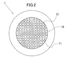
- FIG. 2 is a plan view showing the structure of the outer can according to the present embodiment.
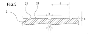
- FIG. 3 is a cross-sectional view showing the structure of the recess of the outer can according to the present embodiment.
- FIG. 4 is a cross-sectional view showing the structure of the all-solid-state battery according to another embodiment.
- the all-solid-state battery according to the embodiment is accommodated between an outer can having a bottom portion, a sealing can having a flat portion and facing the outer can, and the outer can and the sealing can, and the positive electrode material and the negative electrode material.
- a power generation element including a solid electrolyte arranged between the positive electrode material and the negative electrode material is provided, and at least one of the inner surface of the bottom portion of the outer can and the inner surface of the flat surface portion of the sealing can has an uneven structure.
- a conductive sheet having resilience to pressing may be included between at least one inner surface having an uneven structure and the power generation element. The restoration rate of the conductive sheet against pressing may be 7% or more.
- the restoration rate is defined as the thickness of the conductive sheet being t1, the thickness of the conductive sheet when compressed by a predetermined pressing force is t2, and the thickness of the conductive sheet when the pressing force is removed is t3. Sometimes, it means something expressed by the following formula. Further, it is assumed that the conductive sheet has resilience when the restoration rate is equal to or higher than a certain level. (T3-t2) / (t1-t2) x 100 (%) The restoration rate can be measured by the method described in Japanese Industrial Standard JIS R3453 2001 (joint sheet).
- the conductive sheet may be a graphite sheet.
- a conductive sheet for example, a graphite sheet or a conductive tape, between the inner surface of the bottom of the outer can and the inner surface of the flat surface of the sealing can, which has an uneven structure, and the power generation element. It is possible to prevent the problem that the power generation element comes into contact with the uneven structure and is damaged.
- the conductive sheet having resilience to pressing has excellent conductivity and flexibility. Therefore, the conductive sheet can function as a current collector and can absorb expansion and contraction due to charging and discharging of the power generation element, or pressing force when crimping the outer can and the sealing can. As a result, the all-solid-state battery can suppress deterioration of battery performance due to damage to the power generation element and formation of gaps.
- the conductive sheet has an appropriate stability with a restoration rate of 7% or more against expansion due to charging of the power generation element or compression due to pressing force when caulking the outer can and the sealing can. There is.
- the conductive sheet since the conductive sheet appropriately presses the power generation element, it is possible to maintain good continuity between the inner surface of the bottom of the outer can and the power generation element, and the inner surface of the flat surface of the sealing can. It is possible to maintain good continuity between the battery and the power generation element, and it is possible to maintain the battery performance.
- the conductive sheet has an uneven structure formed on at least one of the inner surface of the bottom of the outer can and the inner surface of the flat surface of the sealing can, thereby increasing the contact area with at least one inner surface having the uneven structure, that is, the current collecting area. be able to. As a result, the all-solid-state battery can maintain the battery performance more.
- the graphite sheet may have an apparent density of 0.3 to 1.5 g / cm 3. This is because if the apparent density is too low, the conductivity of the graphite sheet is low, and if the apparent density is too high, the flexibility is lowered.
- the conductive sheet may have a thickness of 0.05 to 0.5 mm. If this thickness is too small, the resilience of the conductive sheet to compression will be insufficient, and if it is too large, the conductive sheet will squeeze the space inside the all-solid-state battery, reducing the capacity of the power generation element. is there.
- the all-solid-state battery 1 is basically made of graphite arranged between the outer can 2, the sealing can 3, the power generation element 4, and the outer can 2 and the power generation element 4. It is composed of a sheet 5 and a graphite sheet 5 arranged between the sealing can 3 and the power generation element 4.
- the all-solid-state battery 1 is a flat battery.
- the conductive sheet may be a conductive tape.
- the outer can 2 includes a circular bottom portion 21 and a cylindrical cylindrical side wall portion 22 formed continuously from the outer periphery of the bottom portion 21.
- the tubular side wall portion 22 is provided so as to extend substantially perpendicular to the bottom portion 21 in a vertical cross-sectional view.
- the outer can 2 is made of a metal material such as stainless steel.
- the inner surface of the bottom 21 of the outer can 2 has an uneven structure.
- the recess 23 is formed on the inner surface of the bottom 21 by knurling.
- the recess 23 is formed on the inner surface of the bottom portion 21 so as to face the lower surface of the power generation element 4.
- FIG. 2 is a plan view showing the structure of the inner surface of the bottom portion 21 of the outer can 2.
- the recesses 23 are formed in a substantially lattice shape by a plurality of grooves extending in the vertical direction shown at uniform intervals and a plurality of grooves extending in the horizontal direction shown at uniform intervals. ing.
- the convex portion 24 is formed adjacent to the concave portion 23.
- the recess 23 is not limited to a substantially grid shape in a plan view.
- the plan view shape of the recess 23 may be a vertical stripe shape extending in parallel in the vertical direction, and a recess such as a circular shape or a ring shape.
- a plurality of 23 may be in the shape of polka dots arranged in a predetermined balance.
- a plurality of circular or ring-shaped convex portions 24 may be arranged in a predetermined balance, such as a polka dot shape.
- the uneven structure includes a structure in which a concave portion 23 is provided in a part of the bottom portion 21, and also includes a structure in which a convex portion 24 is provided in a part of the bottom portion 21. Since the inner surface of the bottom 21 of the outer can 2 has an uneven structure, the friction between the bottom 21 of the outer can 2 and the graphite sheet 5 becomes large (see FIG. 1). As a result, the all-solid-state battery 1 can prevent the graphite sheet 5 from being displaced when it receives vibration or impact.
- the recess 23 is formed with dimensions such that the depth a is 0.01 mm, the width b on the opening side is 0.06 mm, and the width c on the bottom side is 0.05 mm.
- the convex portion 24 is formed with a width d of 0.49 mm.
- the depth a of the recess 23 is preferably 0.005 mm or more, more preferably 0.007 mm or more, and the depth a is preferably 0.02 mm or less, more preferably 0.015 mm or less.
- the width b on the opening side of the recess 23 is preferably 0.03 mm or more, more preferably 0.04 mm or more, and the width b is preferably 0.09 mm or less, more preferably 0.08 mm or less.
- the width c on the bottom side of the recess 23 is preferably 0.02 mm or more, more preferably 0.03 mm or more, and the width c is preferably 0.08 mm or less, more preferably 0.07 mm or less.
- the width d of the convex portion 24 is preferably 0.30 mm or more, more preferably 0.35 mm or more, and the width d is preferably 0.70 mm or less, more preferably 0.65 mm or less.
- the uneven structure By forming the uneven structure with such dimensions, it becomes easy to bring the graphite sheet 5 into contact with the inner surface of the bottom 21 of the outer can 2. That is, if the depth a of the recess 23 is too deep, it becomes difficult for the recess 23 to come into contact with the graphite sheet 5, and if the depth a is too shallow, the contact area with the graphite sheet 5 decreases. Further, if the width b on the opening side of the recess 23 is too narrow, it becomes difficult for the graphite sheet 5 to enter the recess 23, and if the width b on the opening side is too wide, the width d of the convex portion 24 becomes narrow.
- the width d of the convex portion 24 is narrowed, it becomes difficult for the graphite sheet 5 to be received by the surface on the upper surface of the convex portion 24.
- the concave portions 23 are formed in a grid pattern as described above, the upper surface of the convex portion 24 becomes a narrow convex shape as the width d becomes narrower. Since the graphite sheet 5 is pressed toward the bottom 21 side of the outer can 2 by the power generation element 4, it may hit the convex shape and be damaged. Therefore, the width d of the convex portion 24 is preferably formed wider than the width b on the opening side of the concave portion 23.
- the graphite sheet 5 is preferably in contact with the upper surface of the convex portion 24 formed relatively widely.
- the depth a of the concave portion 23, the width c on the opening side, and the width d of the convex portion 24 are preferably determined in a well-balanced manner.
- the width c on the bottom side of the recess 23 is preferably formed narrower than the width b on the opening side from the viewpoint of ease of contact with the graphite sheet 5.
- the sealing can 3 includes a circular flat surface portion 31 and a cylindrical peripheral wall portion 32 formed continuously from the outer periphery of the flat surface portion 31.
- the opening of the sealing can 3 faces the opening of the outer can 2.
- the sealing can 3 is made of a metal material such as stainless steel.
- An uneven structure is also formed on the inner surface of the flat surface portion 31 of the sealing can 3. Since the concave portion 33 and the convex portion 34 have the same configuration as the concave portion 23 and the convex portion 24 of the outer can 2 described above, the description thereof will be omitted. Further, since the inner surface of the flat surface portion 31 of the sealing can 3 has an uneven structure, the friction between the flat surface portion 31 of the sealing can 3 and the graphite sheet 5 increases (see FIG. 1). As a result, the all-solid-state battery 1 can prevent the graphite sheet 5 from being displaced when it receives vibration or impact.
- the outer can 2 and the sealing can 3 accommodate the power generation element 4 and the graphite sheet 5 in the internal space, and then insert a gasket 6 between the tubular side wall portion 22 of the outer can 2 and the peripheral wall portion 32 of the sealing can 3. It is crimped through.
- the outer can 2 and the sealing can 3 have the openings of the outer can 2 and the sealing can 3 facing each other, and the peripheral wall portion 32 of the sealing can 3 is provided inside the tubular side wall portion 22 of the outer can 2. After being inserted, it is crimped between the tubular side wall portion 22 and the peripheral wall portion 32 via the gasket 6. As a result, the internal space formed by the outer can 2 and the sealing can 3 is sealed.
- the outer can 2, the sealing can 3, and the gasket 6 are configured in the same manner as the well-known flat battery, and the material, shape, and the like thereof are not particularly limited.
- the power generation element 4 includes a positive electrode material 41, a negative electrode material 42, and a solid electrolyte 43.
- the solid electrolyte 43 is arranged between the positive electrode material 41 and the negative electrode material 42.
- the power generation element 4 is laminated in the order of the positive electrode material 41, the solid electrolyte 43, and the negative electrode material 42 from the bottom 21 side (lower part in the drawing) of the outer can 2.
- the power generation element 4 is formed in a cylindrical shape.
- the power generation element 4 is arranged on the inner surface of the bottom 21 of the outer can 2 via a graphite sheet 5. Therefore, the outer can 2 functions as a positive electrode can. Further, the power generation element 4 is in contact with the inner surface of the flat surface portion 31 of the sealing can 3 via the graphite sheet 5.
- the sealing can 3 functions as a negative electrode can.
- the power generation element 4 is not limited to the cylindrical shape, and can be variously changed according to the shape of the all-solid-state battery 1, such as a rectangular parallelepiped shape and a polygonal prism shape.
- the positive electrode material 41 contains LiNi 0.6 Co 0.2 Mn 0.2 O 2 having an average particle size of 3 ⁇ m and a sulfide solid electrolyte (Li 6 PS 5 Cl) as positive electrode active materials used in a lithium ion secondary battery.
- This is a positive electrode pellet formed into a cylindrical shape by putting 180 mg of a positive electrode mixture containing carbon nanotubes, which are conductive aids, in a mass ratio of 55:40: 5 into a mold having a diameter of 10 mm.
- the positive electrode material 41 is not particularly limited as long as it can function as the positive electrode material of the power generation element 4.
- lithium cobalt oxide, lithium nickel oxide, lithium manganate, lithium nickel cobalt manganese composite oxide, and the like are examples of the positive electrode material of the power generation element 4.
- the size and shape of the positive electrode material 41 are not limited to the cylindrical shape, and can be variously changed according to the size and shape of the all-solid-state battery 1.
- the negative electrode material 42 contains LTO (Li 4 Ti 5 O 12 , lithium titanate), a sulfide solid electrolyte (Li 6 PS 5 Cl), and carbon nanotubes as negative electrode active materials used in a lithium ion secondary battery. It is a negative electrode pellet obtained by molding 300 mg of a negative electrode mixture contained in a weight ratio of 50:45: 5 into a cylindrical shape.
- the negative electrode material 42 is not particularly limited as long as it can function as the negative electrode material of the power generation element 4, and is, for example, a carbon material such as metallic lithium, a lithium alloy, graphite, or low crystal carbon, SiO, or LTO.
- the size and shape of the negative electrode material 42 are not limited to the cylindrical shape, and can be variously changed according to the size and shape of the all-solid-state battery 1.
- the solid electrolyte 43 is formed by molding 60 mg of a sulfide solid electrolyte (Li 6 PS 5 Cl) into a cylindrical shape.
- the solid electrolyte 43 is not particularly limited, but may be another sulfur-based solid electrolyte such as an algyrodite type from the viewpoint of ionic conductivity. When a sulfur-based solid electrolyte is used, it is preferable to coat the surface of the positive electrode active material with niobium oxide in order to prevent the reaction with the positive electrode active material.
- the solid electrolyte 43 may be a hydride-based solid electrolyte, an oxide-based solid electrolyte, or the like.
- the size and shape of the solid electrolyte 43 are not limited to the cylindrical shape, and can be variously changed according to the size and shape of the all-solid-state battery 1.
- the graphite sheet 5 is arranged between the bottom portion 21 of the outer can 2 and the positive electrode material 41 of the power generation element 4, and between the flat surface portion 31 of the sealing can 3 and the negative electrode material 42 of the power generation element 4. That is, as shown in FIG. 1, when both the inner surface of the bottom portion 21 of the outer can 2 and the inner surface of the flat surface portion 33 of the sealing can 3 have an uneven structure, graphite sheets are formed on both the upper surface and the lower surface of the power generation element 4. 5 (conductive sheet) is arranged.
- the graphite sheet 5 is formed by rolling expanded graphite.
- the plan view shape of the graphite sheet 5 is formed to be substantially similar to the plan view shape of the internal space of the all-solid-state battery 1.
- the graphite sheet 5 is formed in a substantially circular shape in a plan view.
- the area of the upper surface of the graphite sheet 5 on the outer can 2 side may be the same as the area of the lower surface of the positive electrode material 41 of the power generation element 4, or may be larger than the area of the lower surface of the positive electrode material 41 of the power generation element 4. Good.
- the area of the lower surface of the graphite sheet 5 on the sealing can 3 side may be the same as the area of the upper surface of the negative electrode material 42 of the power generation element 4, or wider than the area of the upper surface of the negative electrode material 42 of the power generation element 4. You may. That is, the upper surface of the graphite sheet 5 on the outer can 2 side may cover the lower surface of the positive electrode material 41.
- the lower surface of the graphite sheet 5 on the sealing can 3 side may cover the upper surface of the negative electrode material 42.
- the graphite sheet 5 is not limited to a substantially circular shape in a plan view, and can be variously changed according to the plan view shape of the all-solid-state battery 1, such as an elliptical shape and a substantially polygonal shape in a plan view.
- the graphite sheet 5 is manufactured as follows. First, the particles of acid-treated graphite obtained by subjecting natural graphite to acid treatment are heated. Then, the acid-treated graphite expands by vaporizing and foaming the acid between the layers. The expanded graphite (expanded graphite) is molded into a felt shape and further rolled using a roll rolling machine to form a sheet body. The graphite sheet 5 is manufactured by hollowing out the expanded graphite sheet body into a circular shape. As described above, expanded graphite is formed by vaporizing the acid and foaming the acid-treated graphite. Therefore, the graphite sheet 5 is formed into a porous sheet. Therefore, the graphite sheet 5 has excellent flexibility due to its porosity as well as the conductivity of graphite itself. The method for producing the graphite sheet 5 is not limited to this, and the graphite sheet 5 may be produced by any method.
- the thickness of the graphite sheet 5 (conductive sheet) is preferably 0.05 mm or more, more preferably 0.07 mm or more, preferably 0.5 mm or less, and more preferably 0.2 mm or less. Good. If the thickness of the graphite sheet 5 is too small, the resilience of the graphite sheet 5 against compression becomes insufficient, and if the thickness is too large, the graphite sheet 5 presses the space of the internal space of the all-solid-state battery 1, and the capacity of the power generation element 4 increases. This is because it decreases.
- the restoration rate of the graphite sheet 5 (conductive sheet) obtained by the above formula is preferably 7% or more. Since the graphite sheet 5 (conductive sheet) has such appropriate resilience, the graphite sheet 5 (conductive sheet) appropriately presses the power generation element 4. As a result, it is possible to maintain good continuity between the inner surface of the bottom 21 of the outer can 2 and the power generation element 4, and it is possible to maintain good continuity between the inner surface of the flat surface portion 31 of the sealing can 3 and the power generation element 4. it can.
- the restoration rate is more preferably 10% or more from the viewpoint of maintaining good continuity.
- the apparent density or thickness of the graphite sheet 5 is preferably determined in a well-balanced manner in consideration of flexibility, resilience, and effective use of the space of the internal space.
- the graphite sheet 5 has excellent conductivity and flexibility. Therefore, the graphite sheet 5 can function as a current collector and absorbs expansion and contraction of the power generation element 4 due to charging and discharging, or pressing force when caulking the outer can 2 and the sealing can 3. Can be done. As a result, the all-solid-state battery 1 can suppress deterioration of battery performance due to damage to the power generation element 4 and formation of gaps.
- the flexible graphite sheet 5 has an appropriate resilience as described above against expansion due to charging of the power generation element or compression due to pressing force when the outer can 2 and the sealing can 3 are crimped. Have.
- the all-solid-state battery 1 can maintain good continuity between the inner surface of the bottom 21 of the outer can 2 and the power generation element 4, and conducts the inner surface of the flat surface portion 31 of the sealing can 3 with the power generation element 4. It can be maintained well and the battery performance can be maintained.
- the graphite sheet 5 can increase the contact area with the bottom portion 21 and the flat surface portion 31, that is, the current collecting area due to the concave-convex structure formed on the inner surface of the bottom portion 21 and the uneven structure formed on the flat surface portion 31. As a result, the all-solid-state battery 1 can further maintain the battery performance.
- an uneven structure may be provided only on the inner surface of the bottom portion 21 of the outer can 2, and the inner surface of the flat surface portion 31 of the sealing can 3 may be formed flat.
- the concave-convex structure may be provided only on the inner surface of the flat surface portion 31 of the sealing can 3, and the inner surface of the bottom portion 21 of the outer can 2 may be formed flat. Even in this case, the above-mentioned effect can be obtained.
- the graphite sheet 5 is arranged adjacent to the inner surface of the sealing can 3 having no uneven structure. However, the graphite sheet 5 is removed and the power generation element 4 is formed on the inner surface of the flat surface portion 31 of the sealing can 3. May be in direct contact. Also in this case, by pressing the power generation element 4 with the graphite sheet 5, it is possible to maintain good continuity between the inner surface of the flat surface portion 31 of the sealing can 3 and the power generation element 4.
- Lithium titanate having an average particle size of 35 ⁇ m, a sulfide solid electrolyte (Li 6 PS 5 Cl), and graphite powder as a conductive auxiliary agent are mixed at a mass ratio of 55:40: 5 and kneaded well.
- a negative electrode mixture was prepared.
- the negative electrode mixture: 150 mg is put onto the solid electrolyte 43 in the powder molding die, pressure molding is performed using a press machine, and the negative electrode material composed of the negative electrode mixture molded body is placed on the solid electrolyte 43. 42 was formed. In this way, the power generation element 4 in which the positive electrode material 41, the solid electrolyte 43, and the negative electrode material 42 are laminated was produced.
- ⁇ Battery assembly> As a metal container for accommodating the power generation element 4, a stainless steel outer can 2 and a sealing can 3 were prepared. As shown in FIGS. 1 to 3, uneven structures (concave portions 23, 33 and convex portions 24, 34) are formed on the inner surface of the bottom portion 21 of the outer can 2 and the inner surface of the flat surface portion 31 of the sealing can 3, respectively, by knurling. did.
- Each of the graphite sheets 5 has a thickness of 0.1 mm, an apparent density of 1.0 g / cm3, a restoration rate of 15%, and is punched into a circular shape having a diameter of 10 mm.
- Each of the graphite sheets 5 was used as a current collector.
- one of the two graphite sheets 5 is sealed with the opening side of the sealing can 3 facing up (flat portion 31 facing down).
- the power generation element 4 was placed on the inner surface of the flat surface portion 31 of the can 3 so that the negative electrode material 42 faces the graphite sheet 5. Further, the other graphite sheet 5 was placed on the positive electrode material 41 side of the power generation element 4. Then, after covering the outer can 2 on the outer can 2, the outer can 2 and the sealing can 3 were crimped and sealed to produce an all-solid-state battery 1 having a coin-shaped shape.
- the all-solid-state battery of Comparative Example 1 is different in that the basic configuration is the same as that of the all-solid-state battery 1 of Example, and a non-woven fabric made of carbon fiber is used as a current collector instead of the graphite sheet 5.
- the thickness of the non-woven fabric made of carbon fiber is 0.2 mm, and the restoration rate is 4%.
- the all-solid-state battery of Comparative Example 2 has the same basic configuration as the all-solid-state battery 1 of the embodiment, and has an uneven structure by knurling on the inner surface of the bottom of the outer can and the inner surface of the flat surface of the sealing can. It differs in that it does not.
- Each all-solid-state battery is constantly charged at a current value of 0.2 C until the voltage reaches 3.1 V, and then at a voltage of 3.1 V until the current value reaches 0.02 C. After that, a constant current was discharged at a current value of 0.2 C until the voltage became 1.2 V. This charge / discharge cycle was repeated for 300 cycles, and the ratio of the discharge capacity in the 300th cycle (capacity retention rate) to the discharge capacity in the second cycle was calculated.
- the all-solid-state battery 1 of the example had a capacity retention rate of 98%, and maintained almost the same discharge capacity as immediately after the start of the charge / discharge cycle even at the 300th cycle. It was found that the all-solid-state battery of Comparative Example 1 had a capacity retention rate of 72%, and the discharge capacity was reduced by about 30% immediately after the start of the charge / discharge cycle at the 300th cycle.
- the all-solid-state battery 1 of the example has appropriate resilience due to the use of the flexible graphite sheet 5 as the current collector, the all-solid-state battery 1 of the comparative example 1, that is, carbon It was found that the battery performance can be maintained as compared with the all-solid-state battery using the non-woven fiber.
- the capacity retention rate of the all-solid-state battery of Comparative Example 2 is 90%, and the capacity retention rate is slightly lower than that of the example. Therefore, in the all-solid-state battery 1 of the first embodiment, uneven structures (concave portions 23, 33 and convex portions 24, 34) are provided on the inner surface of the bottom portion 21 of the outer can 2 and the inner surface of the flat surface portion 31 of the sealing can 3 to collect the batteries. It was found that the battery performance can be maintained more by increasing the electric area.
Landscapes
- Chemical & Material Sciences (AREA)
- Chemical Kinetics & Catalysis (AREA)
- Electrochemistry (AREA)
- General Chemical & Material Sciences (AREA)
- Engineering & Computer Science (AREA)
- Manufacturing & Machinery (AREA)
- Physics & Mathematics (AREA)
- Condensed Matter Physics & Semiconductors (AREA)
- General Physics & Mathematics (AREA)
- Inorganic Chemistry (AREA)
- Materials Engineering (AREA)
- Sealing Battery Cases Or Jackets (AREA)
- Secondary Cells (AREA)
- Connection Of Batteries Or Terminals (AREA)
Abstract
Description
(t3-t2)/(t1-t2)×100(%)
復元率は、日本産業規格JIS R3453 2001(ジョイントシート)に記載された方法で測定することができる。
以下、導電性シートとして黒鉛シートを用いた本開示の実施形態1について、図1を用いて具体的に説明する。まず、図1に示すように、全固体電池1は、基本的には、外装缶2と、封口缶3と、発電要素4と、外装缶2と発電要素4との間に配置された黒鉛シート5と、封口缶3と発電要素4との間に配置された黒鉛シート5とから構成されている。なお、本実施形態では、全固体電池1は、扁平形電池である。また、導電性シートは、導電性テープであってもよい。
図4に示すように、外装缶2の底部21の内面にのみ凹凸構造を設け、封口缶3の平面部31の内面を平面に形成してもよい。或いは、図示はしないが、封口缶3の平面部31の内面にのみ凹凸構造を設け、外装缶2の底部21の内面を平面に形成してもよい。この場合でも、上述した効果を得ることができる。なお、図4では、凹凸構造を設けていない封口缶3の内面に隣接して黒鉛シート5を配置しているが、黒鉛シート5を取り除いて封口缶3の平面部31の内面に発電要素4を直接接触させてもよい。この場合にも、黒鉛シート5が発電要素4を押圧することにより、封口缶3の平面部31の内面と発電要素4との導通を良好に維持することができる。
<正極材の作製>
平均粒子径3μmのLiNi0.6Co0.2Mn0.2O2と、硫化物固体電解質(Li6PS5Cl)と、導電助剤であるカーボンナノチューブ〔昭和電工社製「VGCF」(商品名)〕とを質量比で55:40:5の割合で混合し、よく混練して正極合剤を調製した。次に、正極合剤:90mgを直径10mmの粉末成形金型に入れ、プレス機を用いて10トン/cm2の条件で加圧成形を行い、正極合剤成形体よりなる正極材41を作製した。
次に、粉末成形金型内の正極材41の上に、硫化物固体電解質(Li6PS5Cl):45mgを投入し、プレス機を用いて加圧成形を行い、正極材41の上に固体電解質43を形成した。
平均粒子径35μmのチタン酸リチウムと、硫化物固体電解質(Li6PS5Cl)と、導電助剤である黒鉛粉末とを質量比で55:40:5の割合で混合し、よく混練して負極合剤を調製した。次に、負極合剤:150mgを粉末成形金型内の固体電解質43の上に投入し、プレス機を用いて加圧成形を行い、固体電解質43の上に負極合剤成形体よりなる負極材42を形成した。このようにして、正極材41、固体電解質43及び負極材42が積層された発電要素4を作製した。
発電要素4を収容する金属容器として、ステンレス鋼製の外装缶2及び封口缶3を用意した。図1~3に示すように、外装缶2の底部21の内面と封口缶3の平面部31の内面には、それぞれ凹凸構造(凹部23、33及び凸部24、34)をローレット加工により形成した。
比較例1の全固体電池は、基本的な構成が実施例の全固体電池1と同様であって、黒鉛シート5に代えて炭素繊維製の不織布を集電体として用いた点で異なる。炭素繊維製の不織布の厚みは、0.2mmであり、復元率は4%である。
比較例2の全固体電池は、基本的な構成が実施例の全固体電池1と同様であって、外装缶の底部の内面と封口缶の平面部の内面とにローレット加工による凹凸構造を有していない点で異なる。
実施例の全固体電池1、比較例1の全固体電池及び比較例2の全固体電池を用い、それぞれ以下の条件で容量維持率を算出し、比較した。
2 外装缶、21 底部、22 筒状側壁部、23 凹部、24 凸部
3 封口缶、31 平面部、32 周壁部、33 凹部、34 凸部
4 発電要素、41 正極材、42 負極材、43 固体電解質
5 黒鉛シート(導電性シート)
6 ガスケット
Claims (4)
- 底部を有する外装缶と、
平面部を有し、前記外装缶に対向する封口缶と、
前記外装缶と前記封口缶との間に収容され、正極材と負極材と前記正極材と前記負極材との間に配置される固体電解質とを含む発電要素とを備え、
前記外装缶の底部の内面及び前記封口缶の平面部の内面の少なくとも一方は、凹凸構造を有し、
前記凹凸構造を有する少なくとも一方の内面と前記発電要素との間に、押圧に対し復元性を有する導電性シートを含み、
前記導電性シートの押圧に対する復元率は、7%以上である、全固体電池。 - 請求項1に記載の全固体電池であって、
前記導電性シートは、黒鉛シートである、全固体電池。 - 請求項2に記載の全固体電池であって、
前記黒鉛シートは、0.3~1.5g/cm3のみかけ密度を有する、全固体電池。 - 請求項1に記載の全固体電池であって、
前記導電性シートは、0.05~0.5mmの厚みを有する、全固体電池。
Priority Applications (4)
| Application Number | Priority Date | Filing Date | Title |
|---|---|---|---|
| JP2021540742A JP7030250B2 (ja) | 2019-08-20 | 2020-08-11 | 全固体電池 |
| CN202080056403.1A CN114207917B (zh) | 2019-08-20 | 2020-08-11 | 全固体电池 |
| US17/634,007 US12249725B2 (en) | 2019-08-20 | 2020-08-11 | All-solid-state battery |
| EP20854996.4A EP3996174A4 (en) | 2019-08-20 | 2020-08-11 | SOLID STATE BATTERY |
Applications Claiming Priority (2)
| Application Number | Priority Date | Filing Date | Title |
|---|---|---|---|
| JP2019-150411 | 2019-08-20 | ||
| JP2019150411 | 2019-08-20 |
Publications (1)
| Publication Number | Publication Date |
|---|---|
| WO2021033601A1 true WO2021033601A1 (ja) | 2021-02-25 |
Family
ID=74661064
Family Applications (1)
| Application Number | Title | Priority Date | Filing Date |
|---|---|---|---|
| PCT/JP2020/030619 Ceased WO2021033601A1 (ja) | 2019-08-20 | 2020-08-11 | 全固体電池 |
Country Status (5)
| Country | Link |
|---|---|
| US (1) | US12249725B2 (ja) |
| EP (1) | EP3996174A4 (ja) |
| JP (1) | JP7030250B2 (ja) |
| CN (1) | CN114207917B (ja) |
| WO (1) | WO2021033601A1 (ja) |
Cited By (4)
| Publication number | Priority date | Publication date | Assignee | Title |
|---|---|---|---|---|
| EP3832775A4 (en) * | 2018-09-26 | 2021-12-08 | Maxell Holdings, Ltd. | SOLID FLAT BATTERY AND METHOD FOR MANUFACTURING THE SAME |
| JPWO2022113989A1 (ja) * | 2020-11-25 | 2022-06-02 | ||
| JP2022127063A (ja) * | 2021-02-19 | 2022-08-31 | セイコーインスツル株式会社 | 非水電解質二次電池及び非水電解質二次電池の製造方法 |
| WO2023153582A1 (ko) * | 2022-02-10 | 2023-08-17 | 삼성에스디아이 주식회사 | 전고체 전지용 탄성 시트 조성물, 이로부터 제조된 전고체 전지용 탄성시트, 및 이를 포함하는 전고체 전지 |
Citations (8)
| Publication number | Priority date | Publication date | Assignee | Title |
|---|---|---|---|---|
| JPS584053B2 (ja) | 1973-08-20 | 1983-01-24 | ザ ビ− エフ グツドリツチ カムパニ− | シヨクバイトシテ hmf6 サンノ トリアルキルオキソニウムエンオ モチイル エピハロヒドリンノ ジユウゴウホウホウ |
| JPS59119563U (ja) * | 1983-01-31 | 1984-08-11 | 日本電気ホームエレクトロニクス株式会社 | 電池 |
| JPH0426050A (ja) * | 1990-05-18 | 1992-01-29 | Matsushita Electric Ind Co Ltd | リチウム電池 |
| JPH08115710A (ja) * | 1994-10-14 | 1996-05-07 | Hitachi Maxell Ltd | 扁平形電池 |
| JP2002042744A (ja) * | 2000-07-31 | 2002-02-08 | Toshiba Battery Co Ltd | 扁平形非水電解質二次電池 |
| JP2005056827A (ja) * | 2003-07-23 | 2005-03-03 | Matsushita Electric Ind Co Ltd | コイン型全固体電池 |
| JP2005228705A (ja) | 2004-02-16 | 2005-08-25 | Nec Corp | 蓄電デバイス |
| JP2017152299A (ja) | 2016-02-26 | 2017-08-31 | セイコーインスツル株式会社 | 非水電解質二次電池及びその製造方法 |
Family Cites Families (11)
| Publication number | Priority date | Publication date | Assignee | Title |
|---|---|---|---|---|
| JPS5813461U (ja) * | 1981-07-20 | 1983-01-27 | 三洋電機株式会社 | ヒ−トポンプ式空気調和機 |
| US6413486B2 (en) * | 1998-06-05 | 2002-07-02 | Matsushita Electric Industrial Co., Ltd. | Nonaqueous secondary battery, constituent elements of battery, and materials thereof |
| EP1638158A4 (en) * | 2003-05-22 | 2010-08-25 | Panasonic Corp | SECONDARY BATTERY WITH A WATER-FREE ELECTROLYTE AND METHOD FOR THE PRODUCTION THEREOF |
| JP2005243274A (ja) * | 2004-02-24 | 2005-09-08 | Toshiba Corp | 非水系角型二次電池 |
| JP3742422B1 (ja) * | 2005-03-17 | 2006-02-01 | 日立マクセル株式会社 | 扁平形電池 |
| JP4839111B2 (ja) * | 2005-04-04 | 2011-12-21 | パナソニック株式会社 | リチウム二次電池 |
| JP5804053B2 (ja) | 2011-04-15 | 2015-11-04 | 株式会社村田製作所 | 固体電池 |
| JP5861444B2 (ja) * | 2011-12-20 | 2016-02-16 | ソニー株式会社 | 二次電池用活物質、二次電池および電子機器 |
| US9490472B2 (en) * | 2013-03-28 | 2016-11-08 | Semiconductor Energy Laboratory Co., Ltd. | Method for manufacturing electrode for storage battery |
| CN203553277U (zh) * | 2013-11-20 | 2014-04-16 | 惠州亿纬锂能股份有限公司 | 扣式电池及扣式电池集流器 |
| CN109950543B (zh) * | 2017-12-20 | 2021-08-24 | 天津国安盟固利新材料科技股份有限公司 | 一种适用于锂离子电池电极材料的集流体及其制备和应用 |
-
2020
- 2020-08-11 EP EP20854996.4A patent/EP3996174A4/en active Pending
- 2020-08-11 CN CN202080056403.1A patent/CN114207917B/zh active Active
- 2020-08-11 US US17/634,007 patent/US12249725B2/en active Active
- 2020-08-11 WO PCT/JP2020/030619 patent/WO2021033601A1/ja not_active Ceased
- 2020-08-11 JP JP2021540742A patent/JP7030250B2/ja active Active
Patent Citations (8)
| Publication number | Priority date | Publication date | Assignee | Title |
|---|---|---|---|---|
| JPS584053B2 (ja) | 1973-08-20 | 1983-01-24 | ザ ビ− エフ グツドリツチ カムパニ− | シヨクバイトシテ hmf6 サンノ トリアルキルオキソニウムエンオ モチイル エピハロヒドリンノ ジユウゴウホウホウ |
| JPS59119563U (ja) * | 1983-01-31 | 1984-08-11 | 日本電気ホームエレクトロニクス株式会社 | 電池 |
| JPH0426050A (ja) * | 1990-05-18 | 1992-01-29 | Matsushita Electric Ind Co Ltd | リチウム電池 |
| JPH08115710A (ja) * | 1994-10-14 | 1996-05-07 | Hitachi Maxell Ltd | 扁平形電池 |
| JP2002042744A (ja) * | 2000-07-31 | 2002-02-08 | Toshiba Battery Co Ltd | 扁平形非水電解質二次電池 |
| JP2005056827A (ja) * | 2003-07-23 | 2005-03-03 | Matsushita Electric Ind Co Ltd | コイン型全固体電池 |
| JP2005228705A (ja) | 2004-02-16 | 2005-08-25 | Nec Corp | 蓄電デバイス |
| JP2017152299A (ja) | 2016-02-26 | 2017-08-31 | セイコーインスツル株式会社 | 非水電解質二次電池及びその製造方法 |
Non-Patent Citations (1)
| Title |
|---|
| See also references of EP3996174A4 |
Cited By (6)
| Publication number | Priority date | Publication date | Assignee | Title |
|---|---|---|---|---|
| EP3832775A4 (en) * | 2018-09-26 | 2021-12-08 | Maxell Holdings, Ltd. | SOLID FLAT BATTERY AND METHOD FOR MANUFACTURING THE SAME |
| JPWO2022113989A1 (ja) * | 2020-11-25 | 2022-06-02 | ||
| WO2022113989A1 (ja) * | 2020-11-25 | 2022-06-02 | マクセル株式会社 | ケース付き全固体電池 |
| JP2022127063A (ja) * | 2021-02-19 | 2022-08-31 | セイコーインスツル株式会社 | 非水電解質二次電池及び非水電解質二次電池の製造方法 |
| JP7651314B2 (ja) | 2021-02-19 | 2025-03-26 | セイコーインスツル株式会社 | 非水電解質二次電池及び非水電解質二次電池の製造方法 |
| WO2023153582A1 (ko) * | 2022-02-10 | 2023-08-17 | 삼성에스디아이 주식회사 | 전고체 전지용 탄성 시트 조성물, 이로부터 제조된 전고체 전지용 탄성시트, 및 이를 포함하는 전고체 전지 |
Also Published As
| Publication number | Publication date |
|---|---|
| CN114207917B (zh) | 2024-06-14 |
| US20220320645A1 (en) | 2022-10-06 |
| EP3996174A1 (en) | 2022-05-11 |
| JP7030250B2 (ja) | 2022-03-04 |
| CN114207917A (zh) | 2022-03-18 |
| US12249725B2 (en) | 2025-03-11 |
| JPWO2021033601A1 (ja) | 2021-02-25 |
| EP3996174A4 (en) | 2022-08-24 |
Similar Documents
| Publication | Publication Date | Title |
|---|---|---|
| JP7030250B2 (ja) | 全固体電池 | |
| JP5383616B2 (ja) | 二次電池 | |
| KR100782993B1 (ko) | 이차전지 | |
| JPH1154095A (ja) | 電池およびその製造方法 | |
| JP2008010253A (ja) | リチウム二次電池用電極及びその製造方法、並びにリチウム二次電池 | |
| JP2018092857A (ja) | 非水電解質二次電池用負極及び非水電解質二次電池 | |
| WO2022113989A1 (ja) | ケース付き全固体電池 | |
| JP2020061216A (ja) | 蓄電装置 | |
| JPH11307081A (ja) | リチウムイオン二次電池及びその製造方法 | |
| KR20090035328A (ko) | 스웰링에 의한 극판 변형을 방지하는 구조의 극판 압착판을갖는 전극조립체 및 이를 이용한 전지 | |
| KR100284343B1 (ko) | 이차전지의 전극군 | |
| US10038195B2 (en) | Electrode structure having structured conductive buffer layer | |
| JP7764367B2 (ja) | 全固体電池 | |
| JP7497970B2 (ja) | 全固体電池 | |
| JP7809687B2 (ja) | 円筒形電池 | |
| JP2000357535A (ja) | 角形リチウム二次電池 | |
| CN118056330A (zh) | 蓄能器元件以及制造方法 | |
| JP7256702B2 (ja) | 固体電解質電池 | |
| CN211829022U (zh) | 一种纽扣式锂离子电池 | |
| CN114649564B (zh) | 固态电池 | |
| JP2005243274A (ja) | 非水系角型二次電池 | |
| JP2019175615A (ja) | 電極群及び亜鉛電池 | |
| US10199655B2 (en) | Electrode structure having structured conductive buffer layer | |
| KR20260001343A (ko) | 이차 전지 및 이차 전지의 제조 방법 | |
| WO2012039247A1 (ja) | 角形密閉電池 |
Legal Events
| Date | Code | Title | Description |
|---|---|---|---|
| 121 | Ep: the epo has been informed by wipo that ep was designated in this application |
Ref document number: 20854996 Country of ref document: EP Kind code of ref document: A1 |
|
| ENP | Entry into the national phase |
Ref document number: 2021540742 Country of ref document: JP Kind code of ref document: A |
|
| ENP | Entry into the national phase |
Ref document number: 2020854996 Country of ref document: EP Effective date: 20220202 |
|
| NENP | Non-entry into the national phase |
Ref country code: DE |
|
| WWG | Wipo information: grant in national office |
Ref document number: 17634007 Country of ref document: US |