WO2021033633A1 - 有機物ナノ粒子の製造方法及び有機物ナノ粒子 - Google Patents
有機物ナノ粒子の製造方法及び有機物ナノ粒子 Download PDFInfo
- Publication number
- WO2021033633A1 WO2021033633A1 PCT/JP2020/030862 JP2020030862W WO2021033633A1 WO 2021033633 A1 WO2021033633 A1 WO 2021033633A1 JP 2020030862 W JP2020030862 W JP 2020030862W WO 2021033633 A1 WO2021033633 A1 WO 2021033633A1
- Authority
- WO
- WIPO (PCT)
- Prior art keywords
- slurry
- beads
- stirring rotor
- bead
- bead mill
- Prior art date
- Legal status (The legal status is an assumption and is not a legal conclusion. Google has not performed a legal analysis and makes no representation as to the accuracy of the status listed.)
- Ceased
Links
Images


Classifications
-
- C—CHEMISTRY; METALLURGY
- C07—ORGANIC CHEMISTRY
- C07D—HETEROCYCLIC COMPOUNDS
- C07D233/00—Heterocyclic compounds containing 1,3-diazole or hydrogenated 1,3-diazole rings, not condensed with other rings
- C07D233/54—Heterocyclic compounds containing 1,3-diazole or hydrogenated 1,3-diazole rings, not condensed with other rings having two double bonds between ring members or between ring members and non-ring members
- C07D233/66—Heterocyclic compounds containing 1,3-diazole or hydrogenated 1,3-diazole rings, not condensed with other rings having two double bonds between ring members or between ring members and non-ring members with hetero atoms or with carbon atoms having three bonds to hetero atoms with at the most one bond to halogen, e.g. ester or nitrile radicals, directly attached to ring carbon atoms
- C07D233/72—Two oxygen atoms, e.g. hydantoin
- C07D233/74—Two oxygen atoms, e.g. hydantoin with only hydrogen atoms or radicals containing only hydrogen and carbon atoms, attached to other ring members
-
- A—HUMAN NECESSITIES
- A61—MEDICAL OR VETERINARY SCIENCE; HYGIENE
- A61K—PREPARATIONS FOR MEDICAL, DENTAL OR TOILETRY PURPOSES
- A61K9/00—Medicinal preparations characterised by special physical form
- A61K9/48—Preparations in capsules, e.g. of gelatin, of chocolate
- A61K9/50—Microcapsules having a gas, liquid or semi-solid filling; Solid microparticles or pellets surrounded by a distinct coating layer, e.g. coated microspheres, coated drug crystals
- A61K9/51—Nanocapsules; Nanoparticles
- A61K9/5192—Processes
-
- A—HUMAN NECESSITIES
- A61—MEDICAL OR VETERINARY SCIENCE; HYGIENE
- A61K—PREPARATIONS FOR MEDICAL, DENTAL OR TOILETRY PURPOSES
- A61K31/00—Medicinal preparations containing organic active ingredients
- A61K31/185—Acids; Anhydrides, halides or salts thereof, e.g. sulfur acids, imidic, hydrazonic or hydroximic acids
- A61K31/19—Carboxylic acids, e.g. valproic acid
- A61K31/195—Carboxylic acids, e.g. valproic acid having an amino group
- A61K31/196—Carboxylic acids, e.g. valproic acid having an amino group the amino group being directly attached to a ring, e.g. anthranilic acid, mefenamic acid, diclofenac, chlorambucil
-
- A—HUMAN NECESSITIES
- A61—MEDICAL OR VETERINARY SCIENCE; HYGIENE
- A61K—PREPARATIONS FOR MEDICAL, DENTAL OR TOILETRY PURPOSES
- A61K31/00—Medicinal preparations containing organic active ingredients
- A61K31/21—Esters, e.g. nitroglycerine, selenocyanates
- A61K31/215—Esters, e.g. nitroglycerine, selenocyanates of carboxylic acids
- A61K31/216—Esters, e.g. nitroglycerine, selenocyanates of carboxylic acids of acids having aromatic rings, e.g. benactizyne, clofibrate
-
- A—HUMAN NECESSITIES
- A61—MEDICAL OR VETERINARY SCIENCE; HYGIENE
- A61K—PREPARATIONS FOR MEDICAL, DENTAL OR TOILETRY PURPOSES
- A61K31/00—Medicinal preparations containing organic active ingredients
- A61K31/33—Heterocyclic compounds
- A61K31/395—Heterocyclic compounds having nitrogen as a ring hetero atom, e.g. guanethidine or rifamycins
- A61K31/41—Heterocyclic compounds having nitrogen as a ring hetero atom, e.g. guanethidine or rifamycins having five-membered rings with two or more ring hetero atoms, at least one of which being nitrogen, e.g. tetrazole
- A61K31/4164—1,3-Diazoles
- A61K31/4166—1,3-Diazoles having oxo groups directly attached to the heterocyclic ring, e.g. phenytoin
-
- A—HUMAN NECESSITIES
- A61—MEDICAL OR VETERINARY SCIENCE; HYGIENE
- A61K—PREPARATIONS FOR MEDICAL, DENTAL OR TOILETRY PURPOSES
- A61K31/00—Medicinal preparations containing organic active ingredients
- A61K31/33—Heterocyclic compounds
- A61K31/395—Heterocyclic compounds having nitrogen as a ring hetero atom, e.g. guanethidine or rifamycins
- A61K31/41—Heterocyclic compounds having nitrogen as a ring hetero atom, e.g. guanethidine or rifamycins having five-membered rings with two or more ring hetero atoms, at least one of which being nitrogen, e.g. tetrazole
- A61K31/42—Oxazoles
-
- A—HUMAN NECESSITIES
- A61—MEDICAL OR VETERINARY SCIENCE; HYGIENE
- A61K—PREPARATIONS FOR MEDICAL, DENTAL OR TOILETRY PURPOSES
- A61K31/00—Medicinal preparations containing organic active ingredients
- A61K31/33—Heterocyclic compounds
- A61K31/395—Heterocyclic compounds having nitrogen as a ring hetero atom, e.g. guanethidine or rifamycins
- A61K31/495—Heterocyclic compounds having nitrogen as a ring hetero atom, e.g. guanethidine or rifamycins having six-membered rings with two or more nitrogen atoms as the only ring heteroatoms, e.g. piperazine or tetrazines
- A61K31/496—Non-condensed piperazines containing further heterocyclic rings, e.g. rifampin, thiothixene or sparfloxacin
-
- A—HUMAN NECESSITIES
- A61—MEDICAL OR VETERINARY SCIENCE; HYGIENE
- A61K—PREPARATIONS FOR MEDICAL, DENTAL OR TOILETRY PURPOSES
- A61K31/00—Medicinal preparations containing organic active ingredients
- A61K31/63—Compounds containing para-N-benzenesulfonyl-N-groups, e.g. sulfanilamide, p-nitrobenzenesulfonyl hydrazide
- A61K31/635—Compounds containing para-N-benzenesulfonyl-N-groups, e.g. sulfanilamide, p-nitrobenzenesulfonyl hydrazide having a heterocyclic ring, e.g. sulfadiazine
-
- B—PERFORMING OPERATIONS; TRANSPORTING
- B02—CRUSHING, PULVERISING, OR DISINTEGRATING; PREPARATORY TREATMENT OF GRAIN FOR MILLING
- B02C—CRUSHING, PULVERISING, OR DISINTEGRATING IN GENERAL; MILLING GRAIN
- B02C17/00—Disintegrating by tumbling mills, i.e. mills having a container charged with the material to be disintegrated with or without special disintegrating members such as pebbles or balls
- B02C17/16—Mills in which a fixed container houses stirring means tumbling the charge
-
- B—PERFORMING OPERATIONS; TRANSPORTING
- B02—CRUSHING, PULVERISING, OR DISINTEGRATING; PREPARATORY TREATMENT OF GRAIN FOR MILLING
- B02C—CRUSHING, PULVERISING, OR DISINTEGRATING IN GENERAL; MILLING GRAIN
- B02C17/00—Disintegrating by tumbling mills, i.e. mills having a container charged with the material to be disintegrated with or without special disintegrating members such as pebbles or balls
- B02C17/18—Details
- B02C17/20—Disintegrating members
-
- B—PERFORMING OPERATIONS; TRANSPORTING
- B02—CRUSHING, PULVERISING, OR DISINTEGRATING; PREPARATORY TREATMENT OF GRAIN FOR MILLING
- B02C—CRUSHING, PULVERISING, OR DISINTEGRATING IN GENERAL; MILLING GRAIN
- B02C17/00—Disintegrating by tumbling mills, i.e. mills having a container charged with the material to be disintegrated with or without special disintegrating members such as pebbles or balls
- B02C17/18—Details
- B02C17/24—Driving mechanisms
-
- B—PERFORMING OPERATIONS; TRANSPORTING
- B82—NANOTECHNOLOGY
- B82Y—SPECIFIC USES OR APPLICATIONS OF NANOSTRUCTURES; MEASUREMENT OR ANALYSIS OF NANOSTRUCTURES; MANUFACTURE OR TREATMENT OF NANOSTRUCTURES
- B82Y40/00—Manufacture or treatment of nanostructures
-
- C—CHEMISTRY; METALLURGY
- C07—ORGANIC CHEMISTRY
- C07D—HETEROCYCLIC COMPOUNDS
- C07D261/00—Heterocyclic compounds containing 1,2-oxazole or hydrogenated 1,2-oxazole rings
- C07D261/02—Heterocyclic compounds containing 1,2-oxazole or hydrogenated 1,2-oxazole rings not condensed with other rings
- C07D261/06—Heterocyclic compounds containing 1,2-oxazole or hydrogenated 1,2-oxazole rings not condensed with other rings having two or more double bonds between ring members or between ring members and non-ring members
- C07D261/10—Heterocyclic compounds containing 1,2-oxazole or hydrogenated 1,2-oxazole rings not condensed with other rings having two or more double bonds between ring members or between ring members and non-ring members with hetero atoms or with carbon atoms having three bonds to hetero atoms with at the most one bond to halogen, e.g. ester or nitrile radicals, directly attached to ring carbon atoms
- C07D261/14—Nitrogen atoms
- C07D261/16—Benzene-sulfonamido isoxazoles
-
- C—CHEMISTRY; METALLURGY
- C07—ORGANIC CHEMISTRY
- C07D—HETEROCYCLIC COMPOUNDS
- C07D405/00—Heterocyclic compounds containing both one or more hetero rings having oxygen atoms as the only ring hetero atoms, and one or more rings having nitrogen as the only ring hetero atom
- C07D405/14—Heterocyclic compounds containing both one or more hetero rings having oxygen atoms as the only ring hetero atoms, and one or more rings having nitrogen as the only ring hetero atom containing three or more hetero rings
-
- A—HUMAN NECESSITIES
- A61—MEDICAL OR VETERINARY SCIENCE; HYGIENE
- A61K—PREPARATIONS FOR MEDICAL, DENTAL OR TOILETRY PURPOSES
- A61K9/00—Medicinal preparations characterised by special physical form
- A61K9/48—Preparations in capsules, e.g. of gelatin, of chocolate
- A61K9/50—Microcapsules having a gas, liquid or semi-solid filling; Solid microparticles or pellets surrounded by a distinct coating layer, e.g. coated microspheres, coated drug crystals
- A61K9/5089—Processes
Definitions
- the present disclosure relates to a method for producing organic nanoparticles using a wet bead mill.
- the present disclosure particularly relates to a method for producing nanoparticles of a poorly soluble pharmaceutical compound.
- a crushing process using a jet mill or a bead mill is common.
- the pulverization treatment with a wet bead mill is often performed, and is generally performed as follows.
- a mixture (slurry) of the chemical raw material powder and the dispersion medium prepared in several to several tens of micrometers is prepared and supplied to a bead mill containing a spherical pulverized medium (beads).
- Beads spherical pulverized medium
- the mixture of the slurry and the beads is stirred, and the chemical raw material powder is pulverized.
- an inorganic substance such as zirconia, alumina, hard glass, or silicon carbide, or a polymer material such as polystyrene or polypropylene is used.
- Patent Document 1 describes that the size of beads used for nanomilling is preferably 3 mm or less, more preferably 1 mm or less, and Patent Document 2 uses beads of 10 to 1000 micrometers. It is described that by doing so, even finer particles are pulverized.
- Patent Document 3 describes that it is desirable to use beads of less than 500 micrometers in the pulverization treatment. However, Patent Documents 1 to 3 merely describe the appropriate bead diameter, and do not specifically describe the conditions of the pulverization treatment.
- Patent Document 4 beads of 20 to 200 micrometers are used, and a bead mill device provided with a stirring rotor having a special shape is driven so that the outer peripheral speed of the stirring rotor is 3 to 8 m / sec to perform a crushing process. It is stated that it should be done.
- Patent Document 4 does not describe mixing of debris generated from beads or a stirring rotor into the slurry.
- the crushing efficiency can be improved by using a stirring rotor having a special shape, but the contact area between the beads and the stirring rotor member is increased and a high-speed flow is locally formed. Therefore, the mixing of beads and debris of the stirring rotor member into the slurry can be increased.
- a permissible concentration is set for the content of a substance that may be harmful to health, and this is also applied to nanopharmaceuticals.
- the nano-drug there is a problem that the components are mixed in the drug as the beads and the members of the mill are worn in the pulverization process.
- elements such as zirconium, yttrium, aluminum and silicon, which are components of beads, and elements such as iron, nickel, chromium and tungsten, which are components of metal parts of the mill, are mixed in the chemicals. obtain.
- Patent Document 5 describes that it is desirable that the amount of heavy metals mixed in is less than about 10 ppm in the production of pharmaceutical products, but it is difficult to achieve this by the pulverization treatment using beads.
- Patent Document 5 describes that beads coated with a polymer resin are used as a pulverization medium as a method for reducing the mixture of metallic substances in nano-sized pulverized organic substances. However, even if the mixing of metallic substances from beads can be suppressed, there is a risk that polymer resins will be mixed. Furthermore, metal substances may be mixed in from the parts of the bead mill device, but no solution to this is described.
- a stirring rotor that rotates a mixture containing a slurry containing organic particles and beads having an average particle size of 0.15 mm to 0.9 mm at an outer peripheral speed of 7 m / sec or less in a container of a wet bead mill.
- Method for producing organic nanoparticles including the step of stirring with (2) In the container of the wet bead mill, the slurry containing the organic particles and the value calculated by 0.15 mm or more and 1.07-0.11 ⁇ [outer peripheral speed of the stirring rotor (m / sec)] (
- a method for producing organic nanoparticles which comprises a step of stirring a mixture containing beads having an average particle size of mm) or less with a stirring rotor rotating at an outer peripheral speed of 7 m / sec or less.
- a method for producing organic nanoparticles which comprises a step of stirring a mixture containing a slurry containing organic particles and beads in a container of a wet bead mill with a stirring rotor, wherein the container of the wet bead mill is a vertical type.
- the cylindrical container is provided with an opening at the top of the cylindrical container, and a rotating shaft for rotating the stirring rotor is inserted into the cylindrical container from above the cylindrical container via the opening.
- a manufacturing method, wherein the stirring rotor is connected to the rotating shaft.
- organic powder such as a pharmaceutical compound
- nanoparticles for example, an average particle size of 400 nanometers or less
- contaminants from beads and bead mill parts can be reduced.
- the method of the present disclosure can prevent contamination not only in pharmaceutical products but also in the production of nanoparticles such as health foods and X-ray contrast media.
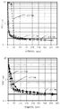
- the time change of the average particle diameter (D50) of the organic powder (phenytoin) in the pulverization treatment is shown.
- the upper graph shows the results using beads with a small particle size ( ⁇ : bead diameter 0.1 mm, ⁇ : bead diameter 0.2 mm, ⁇ : bead diameter 0.3 mm), and the lower graph shows the particle size. This is the result of using large beads ( ⁇ : bead diameter 0.5 mm, ⁇ : bead diameter 0.8 mm, ⁇ : bead diameter 1.0 mm).
- the time change of the contaminant concentration (total concentration of zirconium and yttrium in the slurry: ZY concentration (ppm)) in the pulverization treatment of the organic powder (phenytoin) is shown.
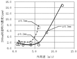
- the effect of the outer peripheral speed (outer peripheral speed) of the stirring rotor on the pulverization processing time is shown.
- ⁇ Bead diameter 0.2 mm, ⁇ : Bead diameter 0.3 mm, ⁇ : Bead diameter 0.5 mm, ⁇ : Bead diameter 0.8 mm.
- the effect of the outer peripheral speed (outer peripheral speed) of the stirring rotor on the concentration of contaminants is shown.
- ⁇ Bead diameter 0.2 mm, ⁇ : Bead diameter 0.3 mm, ⁇ : Bead diameter 0.5 mm.
- the effect of bead diameter on contaminant concentration is shown.
- ⁇ Outer peripheral speed 2 m / sec, ⁇ : Outer peripheral speed 4 m / sec, ⁇ : Outer peripheral speed 6 m / sec.
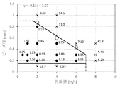
- the relationship between the bead diameter and the outer peripheral speed (outer peripheral speed) of the stirring rotor under suitable pulverization conditions is shown.
- the average particle size is obtained from the particle size distribution measured by a particle size distribution measuring machine, and is expressed as a volume-based median diameter (D50).
- D50 volume-based median diameter
- the value obtained by measuring with LA-950 manufactured by HORIBA, Ltd. is described as the average particle size. If it is a static laser diffraction / scattering type particle size analyzer, almost the same measurement results can be obtained.
- particle size and particle size used in the present specification have the same meaning as the above "average particle size”.
- the "slurry” is a suspension of solid particles of an organic substance of about 100 micrometers or less in a liquid dispersion medium.
- a slurry can be prepared using organic particles having an average particle size of 1 to 100 micrometers, but the method of the present disclosure can be carried out even if the slurry has an average particle size of 100 micrometers or more.
- the pulverization processing speed up to a particle size of 5 micrometers or more is extremely fast, for example, the pulverization processing time from 30 micrometers to 5 micrometers is about 3 minutes, and the entire pulverization is performed. Very short compared to the processing time of 45-400 minutes.
- the influence of the particle size of the organic substance before the pulverization treatment on the operating conditions of the bead mill is small.
- the particle size of the organic particles in the raw material slurry before the pulverization treatment is preferably 1 to 100 micrometers, but if it is 1 ⁇ m or more, there is no substantial effect on the setting of the operating conditions.
- the dispersion medium used in the method of the present disclosure is not particularly limited as long as it is a liquid medium in which the pulverized organic particles are essentially insoluble, and those skilled in the art will appropriately select the dispersion medium according to the properties of the organic particles. be able to.
- water or various organic solvents eg, alcohols such as methanol, ethanol, isopropanol, butanol, ketones such as acetone, methyl ethyl ketone, methyl propyl ketone, methyl isobutyl ketone, ethers such as isopropyl ether, methyl cellosolve, ethylene glycol, Glycol esters such as propylene glycol monomethyl ether acetate and ethylene glycol monoethyl ether acetate, esters such as ethyl acetate, halogenated hydrocarbons such as methylene chloride and trichloroethane, non-aromatic hydrocarbons such as cyclohexane, and aromatic hydrocarbons such as toluene. , Linear hydrocarbons such as normal hexane, etc.).
- organic solvents eg, alcohols such as methanol, ethanol, isopropanol, butanol, ketones such
- the "organic particle” may be any solid particle containing an organic compound, for example, an electronic component.
- examples include, but are not limited to, particles of any organic compound used in various fields such as materials, phosphors, pigments, paints, pharmaceuticals, pesticides, foods and the like.
- organic particles used in the field of pharmaceuticals include, but are not limited to, pharmaceutical compounds used as active ingredients of pharmaceuticals, additives used in pharmaceutical preparations, and those used in the production of X-ray contrast media. ..
- the pharmaceutical compound is not particularly limited, and any compound can be used.
- any compound can be used.
- Examples include, but are not limited to, fervinac, diferonac, acemetacin, alcrophenac, fembufen, lobenzalit, peniciramine, naproxen, pranoprofen, etodolac, cyclosporin, and the like.
- the concentration of organic particles in the slurry is not particularly limited as long as the concentration can obtain fluidity that can be pulverized by a bead mill.
- the slurry concentration is shown as% by weight of the object to be pulverized (organic particles) with respect to the weight of the entire slurry.
- the slurry concentration used in the method of the present disclosure is, for example, an arbitrary concentration in the range of 1 to 70% by weight, 2 to 65% by weight, 3 to 60% by weight, 4 to 55% by weight, and 5 to 50% by weight. Can be mentioned.
- organic nanoparticles refers to the above-mentioned organic particles as having a nanometer size with an average particle size of less than 1 nanometer, for example, an average particle size of 500 nanometers or less, 400 nanometers or less, 300 nanometers or less. It means particles obtained by crushing to 200 nanometers or less, 100 nanometers or less, 50 nanometers or less, and 20 nanometers or less (also referred to as “nano crushing” in the present specification).
- the organic particles are pulverized by rotating the stirring rotor fixed to the rotating shaft in the container of the wet bead mill and stirring the mixture of the slurry and the beads.
- the container of the wet bead mill that can be used in the method of the present disclosure has an inner wall surface forming a point-symmetrical circle with respect to the central axis, and the diameter of the inner wall surface is constant in the direction parallel to the central axis. May also change. In addition, there may be a portion that is not point-symmetrical due to a slurry supply port or the like.
- the wet bead mill that can be used in the method of the present disclosure is for stirring a mixture of beads and slurry in a container such as reinforced alumina, silicon carbide, Sialon (SiAlON), partially stabilized zirconia, and stainless steel.
- the outside of the container may be water-cooled as a jacket structure.
- the capacity of the wet bead mill that can be used in the method of the present disclosure is a capacity generally used in the art, for example, any capacity of 0.15 L to 10 L (0.15 L, 0.5 L, 1 L). , 2L, 5L, 10L, etc.).
- stirring rotor one made of hard ceramics such as reinforced alumina, silicon carbide, sialon, and partially stabilized zirconia can be used, but a stirring rotor made of partially stabilized zirconia is preferable.
- partially stabilized zirconia contains 4 to 6% by weight of ytttrium oxide as an additive with respect to 94 to 96% by weight of zirconium oxide, and another oxide is added in addition to this. ..
- the partially stabilized zirconia has high toughness as well as strength, and local defects are unlikely to occur. Therefore, the stirring rotor made of partially stabilized zirconia has an advantage that less debris is generated.
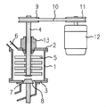
- the method of the present disclosure can be carried out using, for example, a wet bead mill device as shown in FIGS. 1 to 4, but the device is not limited to these devices and is generally used in the art. Can be carried out using.
- the bead mill used in the method of the present disclosure is a vertical bead mill (device 1) of the type shown in FIG. 1, in which the slurry is supplied from the upper part and discharged from the lower part.
- the container of the bead mill is a vertical cylindrical container, which has an opening at the top, and a rotary shaft 4 connected to a drive device such as a rotary shaft pulley 9 is inserted into the cylindrical container from above the cylindrical container via the opening. It is inserted in the vertical direction, and a stirring rotor 5 is connected to the rotating shaft 4.
- a mechanical seal 13 is installed at the connection portion between the rotating shaft 4 and the cylindrical container. The slurry flows from the top to the bottom, separates the beads by the slit type bead separator 8, and then is discharged from the lower part of the cylindrical container.
- the bead mill used in the method of the present disclosure is a vertical bead mill (device 2) of the type shown in FIG. 2, in which the slurry is supplied from the lower part and discharged from the upper part.
- the container of the bead mill is a vertical cylindrical container, which has an opening at the top of the cylindrical container, and a rotating shaft 4 connected to a drive device such as a rotating shaft pulley 9 is cylindrical from above the cylindrical container via the opening. It is inserted vertically into the container.
- a stirring rotor 5 and a centrifugal bead separating device 14 are connected to the rotating shaft 4.
- Two mechanical seals 13 are installed at the connecting portion of the cylindrical container. After the beads are separated by the centrifugal bead separating device 14, the slurry rises in the hollow flow path installed in the rotating shaft and is discharged from the discharge port 7.
- the wet bead mill device is generally provided with a mechanical seal or a similar sealing device for the purpose of sealing between the rotating shaft and the cylindrical container.
- a mechanical seal or a similar sealing device for the purpose of sealing between the rotating shaft and the cylindrical container.
- the material of the contact portion between the rotating portion and the fixing portion of the mechanical seal include high-strength metals such as iron, nickel, molybdenum, tungsten, chromium, and silicon, and high-strength ceramics, and a sealing device during crushing with a bead mill. These can be mixed into the slurry as the ceramic wears. Therefore, the concentration of contaminants can be further reduced by pulverizing the organic powder using a bead mill without a sealing device.
- a vertical cylindrical container is used, and a through hole is provided on the upper surface of the cylindrical container, and the rotating shaft is moved from above the cylindrical container through the through hole.
- a structure that is inserted into the cylindrical container and has a stirring rotor connected to the rotating shaft can be mentioned.
- a mechanism for supplying and discharging the slurry into the cylindrical container without a mechanical seal of the rotating portion is required. As an embodiment, an example of such a device is shown in FIG.
- the bead mill (device 3) of FIG. 3 has the same structure and capacity as the above device 1, but has an open connection between the rotating shaft and the cylindrical container, and is a circulation type wet bead mill without a sealing device.
- a rotary shaft 4 connected to a drive device such as a rotary shaft pulley 9 is vertically inserted into a cylindrical container via a slurry storage tank 15 and a connecting pipe line 16.
- a stirring rotor 5 is connected to the rotating shaft 4.
- the slurry flows from the circulation tank 20 into the slurry storage tank 15 via the slurry connecting pipe 22, and further flows into the cylindrical container via the connecting pipe 16.
- the slurry pulverized while descending in the cylindrical container is discharged to the outside of the cylindrical container from the slurry discharge port 7 after the beads are separated by the plug-type bead separator 8.
- the slurry is further returned to the circulation tank 20 by the pump 19 via the slurry pipe 18.
- a pumping device 17 may be installed on the rotating shaft 4 in the connecting pipe 16 to push the slurry downward.
- bead mills without other types of sealing devices can be applied to the method of the present disclosure.
- examples of other types of bead mills have the following structures. There is a slurry storage tank above the cylindrical container, and a through hole connecting the cylindrical container and the slurry storage tank is installed, and a rotation shaft extends into the cylindrical container through the through hole, and a stirring rotor is provided there. Is connected to.
- the rotating shaft in the through hole has a structure in which the slurry is flowed from the slurry storage tank to the cylindrical container by a pumping mechanism for circulation, a blade for turning the slurry, and the like. This flow can prevent beads from leaking through the through holes.
- the slurry flowing downward through the through hole returns to the slurry storage tank via the centrifugal bead separating device and the hollow flow path.
- the stirring rotor has a plurality of rod-shaped pins installed, but the stirring rotor has a plurality of horizontally arranged disks installed in the height direction.
- a plurality of plate-shaped objects installed in the vertical direction may be used.
- the rotation speed of the stirring rotor is relatively slow, so that the bead mill used is preferably a vertical bead mill.
- centrifugal force acts in the direction perpendicular to gravity, and the force applied to the beads is almost constant in the circumferential direction inside the cylindrical container, so there is no local excessive force acting and it is uniform. High sex.
- the flow direction of the slurry in the cylindrical container of the bead mill may be either an upward flow or a downward flow, but by flowing the slurry downward, the beads can be filled downward, and the beads can be filled together at the bottom of the cylindrical container. Since the contact frequency is improved, it is more preferable to use a vertical bead mill such as the device 1 or the device 3 in which the slurry flows from the top to the bottom. However, since the flow speed of the slurry in the vertical direction is low, the difference is small, and the method of the present disclosure can also be carried out by using a vertical bead mill in which the slurry flows from the bottom to the top.
- the method of the present disclosure can be implemented even with a horizontal bead mill.
- An example of the horizontal bead mill is the bead mill (device 4) shown in FIG.
- the rotation shaft 4 is installed in the horizontal direction, and a plurality of petal-shaped and perforated stirring rotors 5 installed in parallel with the rotation direction are installed, and the stirring rotor 5 stirs the slurry and beads. To do.
- the treated slurry is discharged out of the cylindrical container after the beads are separated by the screen 23.
- the directions of centrifugal force and gravity differ depending on the position in the circumferential direction in the cylindrical container. At the upper part of the side surface of the cylindrical container, gravity is subtracted from the centrifugal force, and the force for pressing the beads is weakened. On the other hand, in the lower part, the centrifugal force and the gravity are combined, so that the force for pressing the beads becomes stronger.
- the method of the present disclosure is carried out under the condition that the outer peripheral speed of the stirring rotor (also referred to as "outer peripheral speed" in the present specification) is relatively slow and the centrifugal force is small, the degree of the above-mentioned phenomenon is large and the beads Is difficult to rise to the top of the cylindrical container, which slows down the processing speed. Therefore, in the horizontal bead mill, when the outer peripheral speed is particularly low, the concentration of contaminants is slightly increased as compared with the vertical bead mill, but it can be used in the method of the present disclosure.
- the slurry treatment time per circulation is 3 to 10 minutes, and the circulation treatment is generally performed about 5 to 50 times.
- the general processing time is 30 to 400 minutes, but it may be shorter or longer depending on the capacity of the mill.
- the beads used in the method of the present disclosure are not particularly limited as long as they are usually used for pulverization treatment using a wet bead mill, and those skilled in the art can use the specifications of the bead mill and the characteristics of the object to be pulverized (for example, particles). It can be appropriately selected in consideration of various factors such as hardness, density and particle size), target particle size of fine particles after pulverization, viscosity of slurry and the like.
- bead material used in the bead mill examples include, but are not limited to, glass, alumina, zircon (zirconia-silica ceramics), zirconia, and steel.
- Zirconia is preferable as a material for beads because it has a high hardness and tends to have less debris mixed due to bead deterioration.
- beads made of partially stabilized zirconia are particularly preferable because, as described above, not only strength but also toughness is high and local defects are unlikely to occur.
- partially stabilized zirconia beads are used in the method of the present disclosure.
- beads made of partially stabilized zirconia may be simply referred to as "beads”.
- the "bead filling rate” is the apparent volume (% by volume) of the beads with respect to the effective volume of the cylindrical container of the bead mill (the internal volume of the cylindrical container minus the volume of the stirring rotor).
- a person skilled in the art can appropriately select the bead filling rate in consideration of various factors such as the specifications and operating conditions of the bead mill and the viscosity of the slurry. Generally, it can be appropriately set within the range of 10 to 95% by volume, for example, 15 to 95% by volume, 25 to 90% by volume, 35 to 90% by volume, 50 to 90% by volume, 75 to 90% by volume. It can be set within the range of%.
- the amount of slurry charged into the bead mill can be appropriately selected by those skilled in the art according to the specifications of the bead mill (for example, the capacity of the crushing chamber of the bead mill to be used), operating conditions, and the like.
- the average particle size of beads (also referred to as "bead diameter" in the present specification). ) May be relatively small. Further, the smaller the particle size of the beads, the larger the specific surface area and the faster the pulverization rate. In general, bead wear has two factors, a wear increasing factor due to the specific surface area of the beads and a wear increasing factor due to the mass of a single substance. The former has less wear as the particle size of the beads is larger, and the latter has less wear as the particle size of the beads is smaller. Considering both, it is considered that the bead diameter of the intermediate size has less wear.
- beads having an arbitrary average particle size in the range of 0.15 mm to 0.9 mm can be used, for example, particle size standards 0.15 mm, 0.2 mm, 0.3 mm, 0.
- Commercially available beads as .4 mm, 0.5 mm, 0.6 mm, 0.7 mm, 0.8 mm, or 0.9 mm can be used.
- the surface area of beads is overwhelmingly larger than the surface area of bead mill members.
- the effective internal volume 200 ml the total area of the stirring rotor and the cylindrical inner surface of the container in the range of about 10 5 mm 2
- the total surface area of the beads are of 10 6 ⁇ 10 7 mm 2 orders
- the wear caused by the contact between the beads is overwhelmingly larger than the wear of the members of the bead mill. Therefore, the method of the present disclosure that suppresses the wear of beads varies depending on the shape of the stirring rotor, and the minimum value of the contaminant concentration that can be achieved differs, but in principle, it can be applied to stirring rotors of all shapes and has a complicated shape. Even with a stirring rotor, the effect of the method of the present disclosure can be expected.
- the stirring rotor of the wet bead mill used in the method of the present disclosure includes a stirring rotor in which rod-shaped pins are installed at point-symmetrical positions with respect to the rotation direction, and a stirring rotor composed of a plurality of plates parallel to the rotation direction.
- the pin-shaped stirring rotor does not necessarily have to have a columnar shape, may have a plate shape, or may not have a simple plate shape.
- the "outer peripheral speed” or “outer peripheral speed” means the outer peripheral speed of the stirring rotor during rotation. Under the same bead diameter conditions, the faster the outer peripheral speed of the stirring rotor, the shorter the processing time. In the method of the present disclosure, an outer peripheral speed of 1 m / sec or more is preferable, but even if the outer peripheral speed is 0.5 m / sec, the organic particles can be pulverized to a particle size of about 200 nanometers. The outer peripheral speed of the stirring rotor also affects the wear of the beads and the stirring rotor member.
- the outer peripheral speed of the stirring rotor when the outer peripheral speed of the stirring rotor is 7 m / sec or less, a sufficient processing speed can be maintained and the concentration of contaminants from beads and the stirring rotor member can be significantly suppressed.
- the outer peripheral speed of the stirring rotor in the method of the present disclosure is, for example, an arbitrary speed within the range of 0.5 m / sec to 7 m / sec (for example, 0.5 m / sec, 1 m / sec, 2 m / sec, 3 m / sec). Seconds, 4 m / sec, 5 m / sec, 6 m / sec, 7 m / sec).
- the outer peripheral speed of the stirring rotor is 7 m / sec or less, 0.15 mm or more, and 1.07 to 0.11 ⁇ [outer peripheral speed of the stirring rotor (m / sec)]. It includes a step of grinding with partially stabilized zirconia beads having an average particle size of less than or equal to the calculated value (mm), thereby maintaining a sufficient grinding rate and from the beads and the stirring rotor member. The concentration of contaminants can be significantly suppressed.
- the amount of contaminants contained in the organic nanoparticles obtained by the methods of the present disclosure is, for example, 0.0001 ppm or more and less than 50 ppm, 0.0001 ppm or more, based on the total weight of the obtained particles. It is less than 40 ppm, 0.0001 ppm or more and less than 30 ppm, 0.0001 ppm or more and less than 20 ppm, and 0.0001 ppm or more and less than 10 ppm.
- the concentration of the contaminant is shown as a percentage (mass ppm) of the amount of the contaminant with respect to the total mass of the slurry.
- the “ZY concentration” indicates the total mass of zirconium and yttrium with respect to the mass of the entire slurry as a fraction (mass ppm). In one embodiment, the ZY concentration in the slurry pulverized by the method of the present disclosure is about 5 ppm or less.
- the concentration of contaminants in the slurry can be determined by inductively coupled plasma mass spectrometry (ICP-MS) and other methods commonly used in the art.
- the concentration of heavy metals in the drug substance is one index. Therefore, for example, the concentration of the slurry to be pulverized. When is 50% by weight, it is desirable that the concentration of heavy metals in the entire pulverized slurry is about 5 ppm or less.
- the present disclosure provides a pulverization method for rapidly pulverizing an organic powder with a wet bead mill and reducing the concentration of contaminants, and it is not always necessary to satisfy this condition.
- additives can be added to the slurry as needed.
- a dispersant can be added to the slurry for the purpose of improving the dispersibility of the organic particles in the slurry, preventing aggregation, or stabilizing the dispersed state.
- the dispersant can be appropriately selected in consideration of various factors such as the properties of the organic particles and the dispersion medium, the specifications of the bead mill, and the operating conditions.
- examples of the dispersant include carboxylate (fatty acid salt, etc.), sulfonate (straight-chain alkylbenzene sulfonate, etc.), phosphate (monoalkyl phosphate, etc.), sulfate ester salt (sodium lauryl sulfate, etc.), etc.
- surfactant and high molecular compounds such as hydroxypropyl cellulose (HPC), hypromerose (hydroxypropyl methyl cellulose (HPMC)), methyl cellulose (MC) and polyvinylpyrrolidone (PVP) can be mentioned.
- HPC hydroxypropyl cellulose
- HPMC hypromerose
- MC methyl cellulose
- PVP polyvinylpyrrolidone
- the amount of the dispersant can be appropriately selected by those skilled in the art according to conventional procedures.
- the slurry discharged from the bead mill may be dried according to a conventional procedure in the art to distill off the dispersion medium to form a powder containing organic nanoparticles.
- organic nanoparticles obtained by the methods of the present disclosure are provided.
- the organic nanoparticles of the present disclosure comprise a pharmaceutical compound.
- the form of the organic nanoparticles obtained by the method of the present disclosure is not particularly limited, and the slurry may be the slurry obtained by the method of the present disclosure, or the slurry may be dried and pulverized.
- compositions or materials comprising the organic nanoparticles obtained by the methods of the present disclosure.
- examples of such compositions or materials include electronic component materials such as dielectrics, piezoelectrics, and magnetic materials, phosphors, electrode materials for batteries, pigments, paints, fine ceramics raw materials, abrasives, pharmaceuticals, pesticides, and foods. And so on.
- a pharmaceutical composition comprising the organic nanoparticles obtained by the method of the present disclosure is provided.
- the pharmaceutical composition of the present disclosure uses the organic nanoparticles obtained by the method of the present disclosure, and appropriately, depending on the desired dosage form, some steps (for example, preparation) usually used in the field of pharmaceutical preparation. It can be obtained as a final product after undergoing granulation, sizing, tableting, coating, etc.).
- the operation method of the bead mill used in the method of the present disclosure will be described by taking the device 1 as an example.
- the slurry is supplied from the slurry supply port 6 into a container composed of a cylinder 1, an upper lid 2 and a lower lid 3.
- the mixture of slurry and beads is stirred by the stirring rotor 5 connected to the rotating shaft 4.
- the stirring rotor 5 is composed of a plurality of rod-shaped pins.
- the slurry descends from the slurry supply port 6 in the cylindrical container, and the speed is generally 10 to several tens of mm / sec.
- the organic particles in the slurry are pulverized.
- the treated slurry is discharged from the slurry discharge port 7 to the outside of the cylindrical container after the beads are separated by the plug-type bead separator 8.
- a mechanical seal 13 is installed on the rotating shaft 4 in order to secure the pressure in the bead mill.
- the discharged slurry flows through the pipe by pumping liquid and returns to the circulation tank.
- the slurry is generally processed by circulating it between the circulation tank and the bead mill.
- Test Example 1 Effect of bead diameter on processing time Wet bead mill (Apex Mill 015 type mill manufactured by Hiroshima Metal & Machinery (corresponding to the above “device 1". In the following test examples and examples, this is referred to as “device 1"). ), 5% by weight of phenitoin (Shizuoka Caffeine Industry Co., Ltd., raw material particle size: 16 to 20 ⁇ m), polyvinylpyrrolidone (3% by weight) and sodium lauryl sulfate (0.25% by weight) as dispersants (500 g).
- phenitoin Shizuoka Caffeine Industry Co., Ltd., raw material particle size: 16 to 20 ⁇ m
- polyvinylpyrrolidone 3% by weight
- sodium lauryl sulfate 0.25% by weight
- Partially stabilized zirconia beads of various average particle sizes (particle size standards) (YTZ balls manufactured by Nikkato (hereinafter, the beads used are the same), bead filling rate: 75%) at an outer peripheral speed of 2 m / sec of the stirring rotor. ) was stirred together to carry out a pulverization treatment. Sampling was performed at a predetermined time during the pulverization treatment, and the particle size and contaminant concentration (total concentration of zirconium and yttrium; referred to as "ZY concentration" in the present specification) of the phenytoin particles in the sample were measured.
- ZY concentration total concentration of zirconium and yttrium
- the particle size of the phenytoin particles was measured by LA-950 (manufactured by HORIBA, Ltd.) (the same applies to the following test examples and examples). Measurement condition: Particle refractive index: 1.610 (phenytoin) Set Zero: 60 seconds Measurement time: 60 seconds Number of measurements: 2 Shape: Non-spherical Solvent refractive index: 1.333 (water) Ultrasound: None Particle size standard: Volume The concentration of contaminants in the slurry was measured according to the following procedure (the same applies to the following test examples and examples).
- pulverized sample 0.5 g is weighed in a metal-free container, an internal standard substance (Co) is added, an NMP / HCl / HNO 3 mixed solution (90: 5: 5) is added, and ultrasonic irradiation is performed. It was dissolved to prepare a sample solution. This sample was measured for the concentration (ppm) of contaminants (zirconium and yttrium) in the sample using an inductively coupled plasma mass spectrometer (ICP-MS) device (iCAPQ TM, Thermofisher).
- ICP-MS inductively coupled plasma mass spectrometer
- Nebulizer Coaxial type Nebulizer Spray chamber: Cyclone type Spray chamber Temperature: Constant temperature around 3 ° C Injector inner diameter: 1.0 mm Sample introduction method: Natural suction High frequency power: 1550W Cooling gas flow rate: 14 L / min Auxiliary gas flow rate: 0.8 L / min Measurement mode: KED Collision gas: Helium Addition gas: Oxygen Perista pump rotation speed: 20 rpm Integration time: 0.1 seconds Number of integrations: 3 times The results are shown in FIGS. 5 and 6.
- the ZY concentration is indicated by mass ppm with respect to the weight of the pulverized slurry (the same applies hereinafter).
- pulverization proceeds rapidly until the particle size of phenytoin reaches about 400 nanometers, and when it becomes 400 nanometers or less, the processing speed decreases and the bead diameter becomes large. The impact will be greater.
- the bead diameter was 0.1 mm ( ⁇ in FIG.
- the initial processing speed was slow, and a very small amount of coarse particles of 1 micrometer or more remained, but pulverization was possible up to 200 nanometers.
- the organic powder is relatively soft, even small-diameter beads having a small collision energy of the beads can be crushed.
- small-diameter beads have a large specific surface area, so that the processing speed is high.
- the bead diameter is 0.1 mm, the impact force of the beads is small and it takes time to crush powder of several tens of micrometers or more, but when the particle size of the powder is 8 micrometers or less, it is rapidly crushed. Has advanced. As shown in FIG.
- Test Example 2 Effect of outer peripheral speed on processing time The relationship between the outer peripheral speed and the processing time in the pulverization treatment of the present disclosure was investigated.
- a slurry 500 g containing 5% by weight of phenytoin (raw material particle size: 16 to 20 ⁇ m), polyvinylpyrrolidone (3% by weight) and sodium lauryl sulfate (0.25% by weight) as dispersants was added to the bead diameter.
- partially stabilized zirconia beads (bead filling rate: 75%) of 0.2 mm to 0.8 mm, pulverization treatment was performed to an average particle size of around 200 nanometers. The results are shown in FIG.
- Test Example 3 Effect of outer peripheral speed on contaminant concentration Using the device 1, phenitoin (raw material particle size: 16 to 20 ⁇ m) 5% by weight, polyvinylpyrrolidone (3% by weight) and sodium lauryl sulfate (0.25% by weight) as dispersants. %) Of the slurry (500 g), the outer peripheral speed of the stirring rotor was changed, and the average particle size was 200 nanometers using partially stabilized zirconia beads (bead filling rate: 75%) as in Test Example 2. The particles were pulverized to the vicinity, and the concentration of contaminants (ZY concentration) when the average particle size of the phenitoin particles reached 200 nanometers was measured. The results are shown in FIG.
- Test Example 4 Effect of bead diameter on contamination concentration Using the device 1, phenitoin (raw material particle size: 16 to 20 ⁇ m) 5% by weight, polyvinylpyrrolidone (3% by weight) and sodium lauryl sulfate (0.25% by weight) as dispersants. %) was pulverized to an average particle size of about 200 nanometers in the same manner as in Test Example 2 using partially stabilized zirconia beads (bead filling rate: 75%) having various bead diameters.
- the outer peripheral speed of the stirring rotor was set to 2 m / sec, 4 m / sec, and 6 m / sec, respectively, and the pulverization treatment was performed to determine the concentration of contaminants (ZY concentration) in the slurry when the average particle size of the phenytoin particles reached 200 nanometers. It was measured. The results are shown in FIG.
- the bead diameter used was 0.1 to 1 mm.
- the ZY concentration at each outer peripheral speed was the lowest when the bead diameter was 0.2 to 0.3 mm, and the ZY concentration was high when the bead diameter was small and large.
- FIG. 9 when the outer peripheral speed is 2 m / sec ( ⁇ in FIG.
- the bead diameter is between 0.8 mm and 1.0 mm, and when the outer peripheral speed is 4 m / sec ( ⁇ ), the bead diameter is 0. Between 0.5 mm and 0.8 mm, when the outer peripheral speed was 6 m / sec ( ⁇ ), the ZY concentration increased sharply between the bead diameters of 0.3 mm and 0.5 mm. As shown in FIG. 9, for each peripheral speed, the value of the bead diameter at which the ZY concentration reaches 5 ppm is obtained from the intersection of the straight line connecting the data points of the bead diameter and the horizontal straight line showing the ZY concentration of 5 ppm. The values are listed.
- the ZY concentration was also increased when the bead diameter was small, and when the bead diameter was 0.1 mm, the ZY concentration was higher than when the bead diameter was 0.2 mm. Judging from the graph of FIG. 9, the lower limit of the bead diameter in which the ZY concentration exceeds 5 ppm is approximately 0.15 mm. Therefore, the upper limit of the bead diameter in which the ZY concentration rapidly increases is a value affected by the outer peripheral speed, while the lower limit is about 0.15 mm.
- Test Example 5 Relationship between bead diameter and outer peripheral speed Using the device 1, phenitoin (raw material particle size: 16 to 20 ⁇ m) 5% by weight, polyvinylpyrrolidone (3% by weight) and sodium lauryl sulfate (0.25% by weight) as dispersants. ) Is pulverized together with partially stabilized zirconia beads (bead filling rate: 75%) having various bead diameters shown in the table below at the outer peripheral speed shown in the table below, and the average particle size of the phenitoin particles is obtained. The contamination concentration (ZY concentration) in the slurry was measured when the amount reached around 200 nanometers. As shown in FIG.
- each data shown in the above table was plotted with the horizontal axis representing the outer peripheral speed and the vertical axis representing the bead diameter, and the numerical value (unit per ppm) of the ZY concentration was added to each data point.
- the upper limit of the bead diameter at which the ZY concentration in the slurry at each outer peripheral speed reaches 5 ppm (0.87 mm at an outer peripheral speed of 2 m / s, 0.60 mm at 4 m / s, and 0 at 6 m / s, as determined from FIG. .43 mm) is shown as ⁇ in FIG. As shown in FIG.
- the lower limit value of the bead diameter at which the ZY concentration in the slurry reaches 5 ppm is about 0.15 mm as shown in Test Example 4, and is represented by a horizontal straight line in FIG.
- the ZY concentration in the slurry is suppressed to 5 ppm or less under the condition that the ZY concentration is distributed in the region between the two straight lines.
- the ZY concentration increased sharply.
- Test Example 6 Effect of bead filling rate A slurry containing 5% by weight of phenitoin (raw material particle size: 16 to 20 ⁇ m), polyvinylpyrrolidone (3% by weight) and sodium lauryl sulfate (0.25% by weight) as dispersants was prepared as 0. Using partially stabilized zirconia beads with a diameter of 3 mm, the bead filling rate was changed, and the particles were pulverized at an outer peripheral speed of 2 m / sec to an average particle size of about 200 nanometers in the same manner as in Test Example 1, and average grains of phenitoin particles were obtained. The contamination concentration (ZY concentration) when the diameter reached 200 nanometers was measured.
- ZY concentration contamination concentration
- the treatment time and ZY concentration were 600 minutes at a filling rate of 25%, 0.50 ppm, 330 minutes at a filling rate of 35%, 0.70 ppm, 90 minutes at a filling rate of 75%, 0.99 ppm, and 90 at a filling rate of 90%. It was 1.4 ppm per minute. At a filling rate of 25%, the ZY concentration was low, but the treatment time was long, and at a filling rate of 90%, the treatment time did not change as compared with the filling rate of 75%, and the ZY concentration increased slightly.
- Test Example 7 Effect of slurry concentration
- concentration of phenytoin raw material particle size: 16 to 20 ⁇ m
- partially stabilized zirconia beads with a diameter of 0.3 mm were used (bead filling rate: 75%), 2 m / sec.
- pulverization was performed by the apparatus 1 at the outer peripheral speed of.
- the table below shows the pulverization time until reaching 200 nanometers and the concentration of contaminants (ZY) in the slurry when reaching 200 nm. Even if the phenytoin concentration in the slurry was changed, the grinding time up to 200 nanometers did not change much. Moreover, the ZY concentration did not change significantly.
- the slurry concentration did not affect the ZY concentration.
- the fluidity of the slurry deteriorated, but the pulverization treatment was possible.
- Examples 1-31 Slurries of various organic particles (phenytoin, sulfamethoxazole, fenofibrate, mefenamic acid, itraconazole) were pulverized using the bead mills (devices 1 to 4) shown in FIGS. 1 to 4.
- the bead mill equipment used is as follows (all of the zirconia below contain yttrium as an additive).
- Device 1 Apex Mill 015 type (manufactured by Hiroshima Metal & Machinery).
- the material of the medicine contact part is tungsten carbide, nickel (mechanical seal), reinforced alumina containing zirconia (stator), zirconia (rotor), and perflo (O-ring).
- Device 2 Ultra Apex Mill 015 type (manufactured by Hiroshima Metal & Machinery).
- the material of the contact part is tungsten carbide, nickel (mechanical seal UPPER side, LOWER side), reinforced alumina containing zirconia (stator), zirconia (separator, rotor), and perflo (O-ring).
- Device 3 Experimental prototype.
- the material of the medicine contact part is zirconia-containing reinforced alumina (stator), zirconia (rotor), SUS316L (pumping device), and perflo (O-ring).
- Equipment 4 Dyno Mill Research Lab type [Small wet disperser / crusher for fine beads] (manufactured by Simmal Enterprises).
- the material of the contact part is zirconia (including hafnium) (accelerator, wear bush), SSiC (silicon carbide) (grounding cylinder), nickel, hard chrome plating (screen), Viton (registered trademark) (O). -Ring).
- Table 3 shows the conditions and results of the pulverization treatment of each example. Further, as comparative examples, Comparative Example 1 using reinforced alumina beads and Comparative Examples 2 to 6 in which the outer peripheral speed or the bead diameter is outside the range of the conditions of the present disclosure are shown.
- Concentrations of contaminants are the concentrations of zirconium and yttrium, which are the bead components, the component of reinforced alumina (aluminum), which is the material of the container of the bead mill, and iron, nickel, chromium, and tungsten, which are the main components of the metal parts used in the bead mill. (Represented by mass ppm with respect to the weight of the pulverized slurry).
- Examples 1 to 25 are the results of pulverizing a 500-gram slurry to a final particle size of about 200 nanometers in an apparatus 1 having an effective internal volume of 150 ml.
- the ZY concentration in the slurry (column of "ZrY total” in the table) was 5 ppm or less in each case.
- the processing time was also in the industrially appropriate range. Further, even if the slurry concentration was as high as 50% by weight, the treatment could be performed without extending the treatment time, and the ZY concentration was as low as 1.48 ppm (Example 17).
- Examples 26 and 27 are the results of pulverizing phenytoin with the device 2 having an effective internal volume of 150 ml.
- the ZY concentration was as low as 0.48 ppm.
- Examples 28 to 30 are the results of processing phenytoin in the device 3 having an internal volume of 150 ml, which has almost the same device configuration in the mill as the device 1.
- the ZY concentration was low (maximum 1.07 ppm), and the treatment time was a maximum of 300 minutes, which was an appropriate range.
- the device 3 was not provided with the mechanical seal, the concentrations of nickel and tungsten were lower than those in the case of using the device 1 having the mechanical seal (Examples 1 to 25).
- the mechanical seal is not installed, the effect of reducing the concentration of heavy metal contaminants in the slurry from the metal member was also recognized.
- Example 31 is the result of pulverization using the apparatus 4.
- the device 4 is a horizontal bead mill, and the stirring rotor is a plate in which a plurality of holes are formed.
- pulverization up to 210 nanometers was 70 minutes, which was not a problem.
- the ZY concentration was about 2.1 ppm, which was higher than that when treated with the apparatus 1 under the same operating conditions (about 1.4 ppm in Example 10), but was sufficiently good. It was a good result.
- Comparative Example 1 treated with reinforced alumina beads
- the mixture of aluminum in the slurry was close to 100 ppm, and the concentration of the contaminant was extremely high. This is because reinforced alumina has high strength but low toughness, so that it wears quickly.
- Comparative Examples 2 to 6 are treatments using partially stabilized zirconia beads in the apparatus 1, but the outer peripheral speed or the bead diameter is the condition of the present disclosure (0.15 mm or more and 1.07-0.11 ⁇ [stirring rotor]. It is an example that deviates from the value (mm) or less calculated by the outer peripheral speed (m / sec)]. In all of Comparative Examples 2 to 6, the ZY concentration exceeded 5 ppm, and the maximum value was about 54.5 ppm.
- the present disclosure can be applied to the production of organic nanoparticles such as pharmaceuticals, health foods, and X-ray contrast media.
Landscapes
- Health & Medical Sciences (AREA)
- Chemical & Material Sciences (AREA)
- Engineering & Computer Science (AREA)
- Veterinary Medicine (AREA)
- Public Health (AREA)
- Life Sciences & Earth Sciences (AREA)
- General Health & Medical Sciences (AREA)
- Animal Behavior & Ethology (AREA)
- Medicinal Chemistry (AREA)
- Pharmacology & Pharmacy (AREA)
- Epidemiology (AREA)
- Organic Chemistry (AREA)
- Food Science & Technology (AREA)
- Nanotechnology (AREA)
- Physics & Mathematics (AREA)
- Bioinformatics & Cheminformatics (AREA)
- Emergency Medicine (AREA)
- General Physics & Mathematics (AREA)
- Manufacturing & Machinery (AREA)
- Condensed Matter Physics & Semiconductors (AREA)
- Crystallography & Structural Chemistry (AREA)
- Biomedical Technology (AREA)
- Optics & Photonics (AREA)
- Crushing And Grinding (AREA)
- Pharmaceuticals Containing Other Organic And Inorganic Compounds (AREA)
- Medicinal Preparation (AREA)
- Manufacturing Of Micro-Capsules (AREA)
- Physical Or Chemical Processes And Apparatus (AREA)
Abstract
湿式ビーズミルの容器内にて、有機物粒子を含むスラリーと、0.15mm以上、かつ1.07-0.11×〔攪拌ローターの外周速度(m/秒)〕で計算される値(mm)以下の平均粒径を有するビーズとを含む混合物を、7m/秒以下の外周速度で回転する攪拌ローターにより攪拌する工程を含む、有機物ナノ粒子の製造方法を提供する。
Description
本開示は、湿式ビーズミルを用いた有機物ナノ粒子の製造方法に関する。本開示は、特に、難溶性の医薬化合物のナノ粒子の製造方法に関する。
近年、健康食品や医薬品の粉体をナノメートルサイズまで粉砕(ナノ粉砕)することにより、活性の向上など、機能を改善する処理が試みられている。特に、難溶性薬剤の活性を改善するために、薬剤の粉体をナノサイズまで粉砕する試みが盛んである。また、薬剤粒子をナノサイズまで微細化することにより、薬効の発揮時期を一定にする効果もある。このように、近年では、ナノサイズまで粉砕された薬剤(ナノ薬剤)の研究が進み、実用化されてきている。
有機物粉体のナノ粉砕方法としては、ジェットミルやビーズミルを用いた粉砕処理が一般的である。中でも湿式ビーズミルでの粉砕処理がよく行われており、一般的には以下のようにして行われる。数~数十マイクロメートルに準備された薬剤原料粉体と分散媒の混合物(スラリー)を調製し、球形の粉砕メディア(ビーズ)が入れられているビーズミルに供給する。ビーズミル内で攪拌ローターが高速回転することで、スラリーとビーズとの混合物が攪拌され、薬剤原料粉体が粉砕される。ビーズの材質としては、ジルコニア、アルミナ、硬質ガラス、炭化珪素などの無機物やポリスチレンやポリプロピレンなどの高分子材料が用いられる。
ナノ粉砕に使用されるビーズのサイズとして、特許文献1には、望ましくは3mm以下、より望ましくは1mm以下であると記載されており、特許文献2には、10~1000マイクロメートルのビーズを使用することで、より細かい粒子まで粉砕処理することが記載されている。特許文献3には、粉砕処理において、500マイクロメートル未満のビーズを使用することが望ましいとの記載がある。しかしながら、特許文献1~3には、単に適正なビーズ径が記載されているだけで、粉砕処理の条件についての具体的な記載はない。
特許文献4には、20~200マイクロメートルのビーズを用い、特殊な形状の攪拌ローターを備えたビーズミル装置を、攪拌ローターの外周速が3~8m/秒となるように駆動することにより粉砕処理することが記載されている。しかし、特許文献4には、ビーズや攪拌ローターから発生する破片のスラリーへの混入については記載されていない。特許文献4の粉砕方法では、特殊な形状の攪拌ローターを使用することで粉砕効率は向上し得るが、ビーズと攪拌ローター部材との接触面積が増え、かつ局所的に高速流が形成されることから、ビーズと攪拌ローター部材の破片のスラリーへの混入が増加し得る。
医薬品の分野において、一般に、薬剤には健康を害する可能性のある物質の含有量について許容濃度が設定されており、ナノ薬剤においても、これが適用される。ナノ薬剤においては、粉砕プロセスにおいて、ビーズやミルの部材が摩耗するに伴って、それらの成分が薬剤中に混入する問題がある。湿式ビーズミルでの粉砕処理においては、ビーズの成分であるジルコニウム、イットリウム、アルミニウム、シリコン等の元素や、ミルの金属部品の成分である鉄、ニッケル、クロム、タングステンなどの元素が薬剤中に混入し得る。
これらの元素の原薬中濃度は、規制上の限界値を守る必要があるが、混入物がナノサイズであることから、極力低い濃度にすることが好ましい。特許文献5には、医薬品の製造において、重金属の混入量が約10ppmより少ないことが望ましいが、ビーズを用いた粉砕処理では、これを実現することが難しいと記載されている。
特許文献5には、ナノサイズの有機物粉砕物中の金属物質の混在を低減する方法として、ポリマー樹脂でコーティングしたビーズを粉砕媒体として用いることが記載されている。しかしながら、ビーズからの金属物質の混在は抑制できても、ポリマー樹脂が混在するリスクがある。さらに、ビーズミル装置の部品からも金属物質の混入が考えられるが、これに対する解決策については記載されていない。
このように、従来技術での有機物のナノ粉砕方法においては、単に効率的な粉砕処理ができればよいとの考えしかなく、高速で攪拌ローターを回転させることで、処理速度を維持するというものであった。また、特許文献5のように、金属物質の混入を抑制する方法が知られていたものの、特殊なビーズを使用する必要があり、一般的なビーズでは問題を解決できなかった。しかも、特許文献5に記載の方法では、ビーズのコーティング成分であるポリマー樹脂や、ビーズミル装置の金属部品の成分である重金属(クロム、ニッケル、鉄など)が混入するリスクがあった。
したがって、湿式ビーズミルを用いた有機物粉体のナノ粉砕において、十分な処理速度を維持し、かつビーズやビーズミル装置の部材からの混入物濃度を大幅に抑制することが可能な新しい方法が求められていた。
本明細書は、以下を開示するものである:
(1)湿式ビーズミルの容器内にて、有機物粒子を含むスラリーと、0.15mm~0.9mmの平均粒径を有するビーズとを含む混合物を、7m/秒以下の外周速度で回転する攪拌ローターにより攪拌する工程を含む、有機物ナノ粒子の製造方法、
(2)湿式ビーズミルの容器内にて、有機物粒子を含むスラリーと、0.15mm以上、かつ1.07-0.11×〔攪拌ローターの外周速度(m/秒)〕で計算される値(mm)以下の平均粒径を有するビーズとを含む混合物を、7m/秒以下の外周速度で回転する攪拌ローターにより攪拌する工程を含む、有機物ナノ粒子の製造方法、
(3)ビーズが部分安定化ジルコニアからなる、上記(1)または(2)に記載の製造方法、
(4)湿式ビーズミルの容器内で、攪拌ローターを回転させる回転軸が鉛直方向に設置されている、上記(1)~(3)のいずれかに記載の製造方法、
(5)湿式ビーズミルの容器内にて、有機物粒子を含むスラリーとビーズとを含む混合物を攪拌ローターにより攪拌する工程を含む、有機物ナノ粒子の製造方法であって、該湿式ビーズミルの容器が縦型の円筒容器であり、該円筒容器の上部に開口部を備え、該攪拌ローターを回転させる回転軸が、該円筒容器の上方から該開口部を経由して該円筒容器内に挿入されており、該回転軸に該攪拌ローターが接続している、製造方法、
(6)前記円筒容器の上方にスラリー貯槽があり、該円筒容器と該スラリー貯槽が連絡管路を介して連結しており、前記攪拌ローターを回転させる回転軸が、該スラリー貯槽の上方から該スラリー貯槽及び該連絡管路を経由して該円筒容器内に挿入されており、該回転軸に該攪拌ローターが接続しており、ビーズ分離処理後のスラリーが該円筒容器の下部から排出される、上記(5)に記載の製造方法、
(7)攪拌ローターが7m/秒以下の外周速度で回転する、上記(5)または(6)に記載の製造方法、
(8)ビーズの平均粒径が0.15mm~0.9mmである、上記(5)~(7)のいずれかに記載の製造方法、
(9)ビーズの平均粒径が0.15mm以上、かつ1.07-0.11×〔攪拌ローターの外周速度(m/秒)〕で計算される値(mm)以下である、上記(5)~(7)のいずれかに記載の製造方法、
(10)ビーズが部分安定化ジルコニアからなる、上記(5)~(9)のいずれかに記載の製造方法、および
(11)上記(1)~(10)のいずれかに記載の製造方法によって得られる有機物ナノ粒子。
本開示の方法によって、湿式ビーズミルを用いて、医薬化合物などの有機物粉体をナノ粒子(例えば平均粒径400ナノメートル以下)に粉砕する際に、ビーズやビーズミル部品からの混入物を低減でき、薬剤の汚染を防止できる。本開示の方法は、医薬品のみならず、健康食品やX線造影剤などのナノ粒子の製造においても、汚染の防止が可能である。
本明細書において、「平均粒径」とは、粒度分布測定機で測定した粒度分布から求められるもので、体積基準のメジアン径(D50)として表される。本開示では、堀場製作所製のLA-950を用いて測定して得られた値を平均粒径として記載する。なお、静的レーザー回折/散乱方式の粒度分析計であれば、ほぼ同等の測定結果が得られる。
本明細書において用いられる「粒子径」または「粒径」との用語は、特に定めがない限り、上記「平均粒径」と同意義である。
本明細書において用いられる「粒子径」または「粒径」との用語は、特に定めがない限り、上記「平均粒径」と同意義である。
本明細書において、「スラリー」とは、液体の分散媒中に、おおよそ100マイクロメートル以下の有機物の固体粒子が懸濁したものである。一般的には、平均粒径1~100マイクロメートルの有機物の粒子を用いてスラリーを調製することができるが、100マイクロメートル以上のものであっても、本開示の方法を実施することは可能である。本開示のビーズミルを用いた粉砕方法では、5マイクロメートル以上の粒径までの粉砕処理速度は極めて速く、例えば、30マイクロメートルから5マイクロメートルまでの粉砕処理時間は3分間程度と、全体の粉砕処理時間の45~400分間に対して極めて短い。従って、粉砕処理前の有機物の粒径がビーズミルの運転条件に与える影響は小さい。本開示では、粉砕処理前の原料スラリー中の有機物粒子の粒径は1~100マイクロメートルが望ましいが、1マイクロメートル以上であれば、運転条件の設定に実質的な影響はない。
本開示の方法で使用される分散媒は、粉砕される有機物粒子が本質的に不溶性である液状媒体であれば特に限定されず、当業者であれば、有機物粒子の性状に応じて適宜選択することができる。例えば、水、または様々な有機溶媒(例えば、メタノール、エタノール、イソプロパノール、ブタノール等のアルコール、アセトン、メチルエチルケトン、メチルプロピルケトン、メチルイソブチルケトン等のケトン、イソプロピルエーテル、メチルセロソルブ等のエーテル、エチレングリコール、プロピレングリコールモノメチルエーテルアセテート、エチレングリコールモノエチルエーテルアセテート等のグリコールエステル、酢酸エチル等のエステル、塩化メチレン、トリクロロエタン等のハロゲン化炭化水素、シクロヘキサン等の非芳香族炭化水素、トルエン等の芳香族炭化水素、ノルマルヘキサン等の直鎖状炭化水素等)が挙げられる。
本明細書において、「有機物粒子」(本明細書中、「有機物粉体」ということもある)は、有機化合物を含んでなる固体粒子であれば任意のものであってよく、例えば、電子部品材料、蛍光体、顔料、塗料、医薬品、農薬、食品等の様々な分野で用いられる任意の有機化合物の粒子が挙げられるが、これらに限定されない。医薬品の分野で用いられる有機物粒子としては、医薬品の有効成分となる医薬化合物、医薬製剤に使用される添加剤、X線造影剤などの製造に使用されるものが挙げられるが、これらに限定されない。
医薬化合物としては特に限定されず、任意のものが使用できる。例えば、フェニトイン、メフェナム酸、インドメタシン、イブプロフェン、イトラコナゾール、スルファメトキサゾール、プロブコール、グリセオフルビン、ジゴキシン、ペラパミル、タクロリムス,デキサメタゾン、ハロペリドール、ラミブジン、レバミピド、アリピプラゾール,リスペリドン、ケトプロフェン、フルルビプロフェン、ロキソプロフェン、フェルビナク、ジフェロナク、アセメタシン、アルクロフェナク、フェンブフェン、ロベンザリット、ペニシラミン、ナプロキセン、プラノプロフェン、エトドラク、シクロスポリンなどが挙げられるが、これらに限定されない。
スラリー中の有機物粒子の濃度(本明細書中、「スラリー濃度」ともいう)は、ビーズミルによる粉砕処理が可能な流動性が得られる濃度であれば特に限定されない。本明細書においては、スラリー濃度を、スラリー全体の重量に対する被粉砕物(有機物粒子)の重量%として示す。本開示の方法において用いられるスラリー濃度としては、例えば、1~70重量%、2~65重量%、3~60重量%、4~55重量%、5~50重量%の範囲内の任意の濃度が挙げられる。
本明細書において、「有機物ナノ粒子」とは、上記有機物粒子を、平均粒径1マイクロメール未満のナノメートルのサイズ、例えば平均粒径500ナノメートル以下、400ナノメートル以下、300ナノメートル以下、200ナノメートル以下、100ナノメートル以下、50ナノメートル以下、20ナノメートル以下にまで粉砕(本明細書において「ナノ粉砕」ともいう)することにより得られた粒子を意味する。
本開示の方法では、湿式ビーズミルの容器内にて、回転軸に固定された攪拌ローターを回転させて、前記スラリーとビーズの混合物を攪拌することで有機物粒子が粉砕される。
本開示の方法で用いることができる湿式ビーズミルの容器は、その内壁面が中心軸基準で点対象の円をなすものであり、中心軸と平行方向においては、内壁面の直径が一定であっても、変化していても良い。また、スラリー供給口などのために点対称にならない部分があっても良い。本開示の方法に用いることができる湿式ビーズミルは、強化アルミナ、炭化珪素、サイアロン(SiAlON)、部分安定化ジルコニア、ステンレス鋼などの容器中で、ビーズとスラリーの混合物を攪拌するものである。粉砕処理中の摩擦などによる該容器内のスラリー温度上昇を抑制する必要がある場合に、該容器の外側をジャケット構造として、水冷することがある。本開示の方法に用いることができる湿式ビーズミルの容量は、当技術分野において一般的に使用されている容量であり、例えば0.15L~10Lの任意の容量(0.15L、0.5L、1L、2L、5L、10L等)である。
攪拌ローターは、強化アルミナ、炭化珪素、サイアロン、部分安定化ジルコニアなどの硬質セラッミクス製のものを使用することができるが、部分安定化ジルコニア製の攪拌ローターが好ましい。
ジルコニアは、酸化カルシウムや酸化イットリウムを添加することにより立方晶ジルコニア結晶ができ、高強度となる。さらに、添加物の量を、完全に結晶が安定化する量よりもやや少ない量とする(部分安定化する)ことで、じん性が高まり磨耗や破損に強いセラミックス材料となる。一般的に、部分安定化ジルコニアは、酸化ジルコニウム94~96重量%に対し、添加物として酸化イットリウムを4~6重量%含み、これに加えてさらに他の酸化物が添加されているものである。このように、部分安定化ジルコニアは、強度だけでなく、じん性が高く、局部欠損が起きにいため、部分安定化ジルコニア製の攪拌ローターは破片の発生が少ないという利点がある。
本開示の方法は、例えば図1から図4に示されるような湿式ビーズミル装置を用いて実施することができるが、これらの装置に限らず、当技術分野において一般的に使用されている装置を使用して実施することができる。
一実施形態では、本開示の方法に使用するビーズミルは、図1に示される、スラリーを上部から供給し、下部から排出する形式の縦型ビーズミル(装置1)である。ビーズミルの容器は縦型の円筒容器であり、上部に開口部を備え、回転軸プーリー9などの駆動装置に接続した回転軸4が、円筒容器の上方から開口部を経由して円筒容器内に鉛直方向に挿入されており、回転軸4には攪拌ローター5が接続している。回転軸4と円筒容器の接続部にはメカニカルシール13が設置されている。スラリーは上方から下方に流れ、スリット式ビーズ分離器8によりビーズを分離した後に、円筒容器の下部から排出される。
一実施形態では、本開示の方法に使用するビーズミルは、図2に示される、スラリーを下部から供給し、上部から排出する形式の縦型ビーズミル(装置2)である。ビーズミルの容器は縦型の円筒容器であり、円筒容器の上部に開口部を備え、回転軸プーリー9などの駆動装置に接続した回転軸4が、円筒容器の上方から開口部を経由して円筒容器内に鉛直方向に挿入されている。回転軸4には攪拌ローター5と遠心式ビーズ分離装置14が接続している。円筒容器の接続部には2個のメカニカルシール13が設置されている。スラリーは遠心式ビーズ分離装置14にてビーズが分離された後、回転軸中に設置された中空流路中を上昇して、排出口7から排出される。
上記の装置1および2のように、湿式ビーズミル装置には、一般的に、回転軸と円筒容器の間のシーリングを目的として、メカニカルシール又はそれに類したシーリング装置が設けられる。メカニカルシールの回転部と固定部との接触部の材質としては、鉄、ニッケル、モリブデン、タングステン、クロム、シリコンなどの高強度金属や高強度セラミックスが挙げられ、ビーズミルでの粉砕処理中にシーリング装置の摩耗に伴って、これらがスラリー中に混入し得る。従って、シーリング装置のないビーズミルを用いて有機物粉体を粉砕することで、混入物濃度をさらに低減することができる。
シーリング装置のない湿式ビーズミルとしては、縦型の円筒容器を用いるもので、該円筒容器の上面に貫通孔が施されており、該貫通孔を経由して、回転軸が該円筒容器上方から、該円筒容器内に挿入されており、回転軸には攪拌ローターが接続している構造のものが挙げられる。バッチ式湿式ビーズミルの場合は、上記に記載された装置となるが、循環式の湿式ビーズミルの場合は、回転部のメカニカルシールなしで円筒容器内にスラリーを供給・排出する機構が必要である。一実施形態として、そのような装置の例を図3に示す。
図3のビーズミル(装置3)は、ミル内の構造および容量は上記装置1と同じであるが、回転軸と円筒容器の接続部が開放されたもので、シーリング装置のない循環式湿式ビーズミルの例である。上蓋2の上方にはスラリー貯槽15があり、上蓋2とスラリー貯槽15が連絡管路16で結合している。回転軸プーリー9などの駆動装置に接続した回転軸4がスラリー貯槽15及び連絡管路16を経由して円筒容器内に鉛直方向に挿入されている。回転軸4には攪拌ローター5が接続している。スラリーは、循環タンク20からスラリー連絡管22を経由してスラリー貯槽15に流入し、更に連絡管路16を経由して該円筒容器に流入する。該円筒容器内を下降中に粉砕処理されたスラリーは、プラグ式ビーズ分離器8にてビーズ分離後に、スラリー排出口7から該円筒容器外に排出される。スラリーは、更にポンプ19により、スラリー配管18を経由して、循環タンク20に戻される。スラリー流を改善するために、連絡管路16中の回転軸4にポンピング装置17を設置して、スラリーを下方に押すこともある。
また、他の形式のシーリング装置のないビーズミルも本開示の方法に適用可能である。他形式のビーズミルの例としては、以下の構造のものがある。円筒容器の上方にスラリー貯槽があり、該円筒容器と該スラリー貯槽を結ぶ貫通孔が設置されており、該貫通孔を経由して、回転軸が該円筒容器内に伸びており、そこで攪拌ローターと接続している。円筒容器下部にスラリー供給口があり、スラリーは上昇しながら粉砕処理されて、円筒容器上部に設置されている遠心分離式ビーズ分離装置にてビーズが分離された後、該回転軸中に設置された中空流路中を上昇して、スラリー貯槽に排出される。貫通孔内の回転軸には、図3の装置と同様に、循環用のポンピング機構やスラリー旋回用羽根などにより、スラリーを該スラリー貯槽から該円筒容器に流す構造がある。この流れにより、貫通孔でのビーズ漏洩は防止できる。なお、貫通孔を下方に流れたスラリーは、該遠心分離式ビーズ分離装置と該中空流路を経由して、スラリー貯槽に戻る。
上記の装置1~3のビーズミルでは、攪拌ローターは複数の棒状のピンが設置されたものであるが、攪拌ローターは、水平に配置された円板が高さ方向に複数設置されたものや、縦方向に設置された複数の板状のものなどでも良い。
本開示の方法では、攪拌ローターの回転速度が比較的遅いため、使用するビーズミルは、縦型ビーズミルが好ましい。縦型ビーズミルの場合は、重力と直角方向に遠心力が働き、ビーズに掛かる力が円筒容器内の円周方向でほぼ一定であることから、局部的に過剰な力が働くことがなく、均一性が高い。
ビーズミルの円筒容器中のスラリーの流れ方向は、上方への流れ、下方への流れのいずれでも良いが、スラリーを下方に流すことで、ビーズを下方に充填でき、円筒容器底部でのビーズ同士の接触頻度が向上することから、装置1や装置3のような、スラリーを上方から下方へ流す縦型ビーズミルを使用することがより好ましい。ただし、スラリーの上下方向への流れ速度は低いため、その差は小さく、本開示の方法は、スラリーを下方から上方へ流す縦型ビーズミルを使用しても実施することができる。
また、横型のビーズミルであっても、本開示の方法を実施することができる。横型ビーズミルの例としては、図4に示すビーズミル(装置4)が挙げられる。装置4は、回転軸4が水平方向に設置されており、回転方向に平行に設置された花びら型で穴が開いた攪拌ローター5が複数設置されており、撹拌ローター5がスラリーとビーズを撹拌する。処理が終わったスラリーはスクリーン23でビーズが分離された後に、円筒容器外に排出される。
横型ビーズミルの場合、円筒容器内の円周方向の位置により、遠心力と重力の方向が異なる。円筒容器の側面の上部では遠心力から重力が差し引かれて、ビーズを押し付ける力が弱くなる。一方、下部では、遠心力と重力が合わさるため、ビーズを押し付ける力が強くなる。本開示の方法は、撹拌ローターの外周速度(本明細書中、「外周速」ともいう)が比較的遅く、遠心力が小さい条件下で実施されるため、前述の現象の度合いが大きく、ビーズが円筒容器最上部に上がりづらくなるため、処理速度が低下する。このため、横型ビーズミルでは、外周速度が特に低い場合においては、縦型ビーズミルに比べて混入物濃度がやや増加するが、本開示の方法に使用することは可能である。
循環式の湿式ビーズミルでは、循環1回当りのスラリー処理時間は3~10分間で、5~50回程度の循環処理を行うのが一般的である。一般的な処理時間は30~400分間であるが、ミルの容量によって、これより短くても長くてもよい。
本開示の方法で使用されるビーズは、湿式ビーズミルを用いた粉砕処理に通常使用されるものであれば特に限定されず、当業者であれば、ビーズミルの仕様、被粉砕物の特性(例えば粒子の硬さ、密度および粒径等)、目標とする粉砕後の微粒子の粒径、スラリーの粘度等の様々な因子を考慮して適宜選択することができる。
ビーズミルで用いられるビーズの材質としては、例えば、ガラス、アルミナ、ジルコン(ジルコニア・シリカ系セラミックス)、ジルコニア、スチールなどが挙げられるがこれらに限定されない。ジルコニアは、硬度が高くビーズ劣化による破片の混入が少ない傾向にあるため、ビーズの材質として好ましい。特に、部分安定化ジルコニア製のビーズは、上述のように、強度だけでなく、じん性が高く、局部欠損が起きにいため、特に好ましい。
一実施形態では、本開示の方法において、部分安定化ジルコニア製のビーズが使用される。本明細書中、部分安定化ジルコニア製のビーズを単に「ビーズ」と称することもある。
本明細書において、「ビーズ充填率」とは、ビーズミルの円筒容器の実効容積(円筒容器の内容積から撹拌ローターの容積を引いたもの)に対するビーズの見掛け容積(体積%)である。
ビーズ充填率は、当業者であれば、ビーズミルの仕様や運転条件、スラリーの粘度等の様々な因子を考慮して適宜選択することができる。一般的には、10~95体積%の範囲内で適宜設定することができ、例えば15~95体積%、25~90体積%、35~90体積%、50~90体積%、75~90体積%の範囲内で設定することができる。
ビーズミルに投入されるスラリーの量は、ビーズミルの仕様(例えば、使用するビーズミルの粉砕室の容量)や運転条件等に応じて当業者が適宜選択することができる。
一般的に、有機物粉体は比較的柔らかく、ビーズの衝突エネルギーが小さくても粉砕が可能なため、本開示の方法においては、ビーズの平均粒径(本明細書中、「ビーズ径」ともいう)は比較的小さくても良い。また、ビーズの粒径が小さいほうが比表面積が大きく、粉砕速度は速くなる。一般に、ビーズ摩耗には、ビーズの比表面積による摩耗増加要因と単体質量による摩耗増加要因の二つの要因がある。前者はビーズの粒径が大きいほど摩耗が少なく、後者はビーズの粒径が小さいほど摩耗が少ない。両者を勘案すると、中間サイズのビーズ径がより摩耗が少ないと考えられる。本開示の方法では、0.15mm~0.9mmの範囲内の任意の平均粒径を有するビーズを使用することができ、例えば、粒径規格0.15mm、0.2mm、0.3mm、0.4mm、0.5mm、0.6mm、0.7mm、0.8mm、または0.9mmとして商業的に入手可能なビーズを使用することができる。
一般的に、ビーズの表面積は、ビーズミルの部材の表面積と比べて圧倒的に大きい。例えば、有効内容積200ミリリットルのビーズミル内では、円筒容器内面と撹拌ローターの合計面積が105mm2程度であるのに対し、ビーズの総表面積は106~107mm2のオーダーであり、ビーズ同士の接触による摩耗が、ビーズミルの部材の摩耗と比べて圧倒的に大きい。
したがって、ビーズの摩耗を抑制する本開示の方法は、撹拌ローターの形状によって達成できる混入物濃度の最低値は異なるが、原理的には、全ての形状の撹拌ローターに適用でき、複雑な形状の攪拌ローターであっても、本開示の方法による効果が期待できる。
したがって、ビーズの摩耗を抑制する本開示の方法は、撹拌ローターの形状によって達成できる混入物濃度の最低値は異なるが、原理的には、全ての形状の撹拌ローターに適用でき、複雑な形状の攪拌ローターであっても、本開示の方法による効果が期待できる。
本開示の方法に使用される湿式ビーズミルの撹拌ローターとしては、回転方向に対して点対称位置に棒状のピンが設置されている攪拌ローター、回転方向に平行な複数の板で構成される攪拌ローター、回転軸方向に平行な複数の板で構成される攪拌ローターなどが挙げられる。ピン形状の攪拌ローターは必ずしも円柱状の形状でなくても良く、板状でもよく、また単純な板形状でなくても良い。
本明細書において、「外周速度」または「外周速」とは、攪拌ローターの回転時の外周速度を意味する。
ビーズ径が同じ条件では、一般に、撹拌ローターの外周速度が速いほど処理時間は短くなる。本開示の方法では、1m/秒以上の外周速度が好ましいが、外周速度が0.5m/秒でも有機物粒子を200ナノメートル程度の粒径まで粉砕することは可能である。
また、撹拌ローターの外周速度はビーズや攪拌ローター部材の摩耗にも影響する。本開示の方法では、撹拌ローターの外周速度が7m/秒以下の場合に、十分な処理速度を維持し、かつビーズや攪拌ローター部材からの混入物濃度を大幅に抑制できる。本開示の方法における撹拌ローターの外周速度としては、例えば、0.5m/秒~7m/秒の範囲内の任意の速度(例えば、0.5m/秒、1m/秒、2m/秒、3m/秒、4m/秒、5m/秒、6m/秒、7m/秒)が挙げられる。
一実施形態では、本開示の方法は、撹拌ローターの外周速度が7m/秒以下で、0.15mm以上、かつ1.07-0.11×〔攪拌ローターの外周速度(m/秒)〕で計算される値(mm)以下の平均粒径を有する部分安定化ジルコニア製ビーズを用いて粉砕処理する工程を含み、これにより、十分な粉砕処理速度を維持し、かつビーズや攪拌ローター部材からの混入物濃度を大幅に抑制できる。
一実施形態では、本開示の方法により得られる有機物ナノ粒子に含まれる混入物の量は、得られた粒子の全体の重量に対して、例えば、0.0001ppm以上~50ppm未満、0.0001ppm以上~40ppm未満、0.0001ppm以上~30ppm未満、0.0001ppm以上~20ppm未満、0.0001ppm以上~10ppm未満である。本明細書においては、混入物の濃度を、スラリー全体の質量に対する混入物質量の百万分率(質量ppm)として示す。また、本明細書において「ZY濃度」とは、スラリー全体の質量に対するジルコニウムとイットリウムの質量の合計を百万分率(質量ppm)として示したものである。一実施形態では、本開示の方法により粉砕処理されたスラリー中のZY濃度は約5ppm以下である。
スラリー中の混入物濃度は、誘導結合プラズマ質量分析法(ICP-MS)等の当分野で慣用の測定方法により決定することができる。
スラリー中の混入物濃度は、誘導結合プラズマ質量分析法(ICP-MS)等の当分野で慣用の測定方法により決定することができる。
医薬品の分野においては、特許文献5に記載されるように、原薬中の重金属濃度を10ppm以下とすることは一つの指標となっていることから、例えば、粉砕処理に付されるスラリーの濃度を50重量%とした場合には、粉砕処理されたスラリー全体における重金属の濃度は約5ppm以下であることが望ましい。但し、本開示は、湿式ビーズミルで有機物粉体を迅速に、かつ混入物濃度を低減する粉砕方法を提供するものであり、必ずしも、この条件を満たす必要はない。
本開示の方法の実施に際して、必要に応じ、スラリーに添加剤を配合することができる。例えば、スラリー中の有機物粒子の分散性の向上、凝集の防止または分散状態の安定化を目的として、分散剤をスラリーに配合することができる。
分散剤は、有機物粒子や分散媒の性状、ビーズミルの仕様および運転条件等の様々な因子を考慮して適宜選択することができる。分散剤としては、例えばカルボン酸塩(脂肪酸塩等)、スルホン酸塩(直鎖アルキルベンゼンスルホン酸ナトリウム等)、リン酸塩(モノアルキルリン酸塩等)、硫酸エステル塩(ラウリル硫酸ナトリウム等)等の界面活性剤やヒドロキシプロピルセルロース(HPC)、ヒプロメロース(ヒドロキシプロピルメチルセルロース(HPMC))、メチルセルロース(MC)、ポリビニルピロリドン(PVP)等の高分子化合物が挙げられる。分散剤の量は、当業者が慣用の手順に従って適宜選択することができる。
本開示の方法を実施するために必要な他の粉砕条件は、当業者が、種々の因子(有機物の性質、分散媒の種類、スラリーの粘度、粉砕後に得られるナノ粒子の粒径、粉砕効率等)を考慮して適宜設定することができる。
ビーズミルから排出されたスラリーは、当分野における慣用の手順に従い乾燥して分散媒を留去し、有機物ナノ粒子を含んでなる粉体としてもよい。
本開示のさらなる態様では、本開示の方法によって得られる有機物ナノ粒子が提供される。
一実施形態では、本開示の有機物ナノ粒子は、医薬化合物を含んでなる。
一実施形態では、本開示の有機物ナノ粒子は、医薬化合物を含んでなる。
本開示の方法により得られる有機物ナノ粒子の形態は特に限定されず、本開示の方法により得られたスラリーであってもよいし、そのスラリーを乾燥して粉体化されたものでもよい。
本開示のさらなる態様では、本開示の方法によって得られた有機物ナノ粒子を含んでなる組成物または材料が提供される。このような組成物または材料としては、例えば、誘電体、圧電体、磁性体などの電子部品材料、蛍光体、電池用電極材料、顔料、塗料、ファインセラミックス原料、研磨材、医薬品、農薬、食品等が挙げられる。
本開示のさらなる態様では、本開示の方法によって得られる有機物ナノ粒子を含んでなる医薬組成物が提供される。
本開示の医薬組成物は、本開示の方法によって得られた有機物ナノ粒子を用い、目的とする剤形に応じて適宜、医薬製剤の分野で通常用いられているいくつかの工程(例えば、造粒、整粒、打錠、コーティング等)を経た後、最終製品として得ることができる。
一実施形態として、装置1を例に、本開示の方法で使用するビーズミルの運転方法を説明する。スラリーをスラリー供給口6から円筒1、上蓋2及び下蓋3から構成される容器内に供給する。回転軸4に連結された攪拌ローター5にて、スラリーとビーズの混合物を撹拌する。撹拌ローター5は、複数の棒状ピンからなるものである。スラリーはスラリー供給口6から該円筒容器内を下降していくが、一般的に、その速度は10~数十mm/秒の速度である。攪拌ローター5の攪拌により、スラリー中の有機物粒子は粉砕される。処理を施されたスラリーは、プラグ式ビーズ分離器8にてビーズを分離した後、スラリー排出口7から該円筒容器の外に排出される。ビーズミル内の圧力を確保するために、回転軸4には、メカニカルシール13が設置されている。図1には記載されていないが、排出されたスラリーは、ポンプの送液によりパイプ中を流れて、循環タンクに戻る。このように、スラリーは循環タンクとビーズミルの間を循環して処理されることが一般的である。
以下の試験例および実施例は、本開示をさらに詳細に説明するものであって、いかなる意味においてもその範囲を限定するものとして解釈されるべきではない。
試験例1:処理時間に対するビーズ径の影響
湿式ビーズミル(広島メタル&マシナリー製Apex Mill 015型ミル(上記「装置1」に該当。以下の試験例および実施例ではこれを「装置1」と称する))を用い、フェニトイン(静岡カフェイン工業所、原料粒度:16~20μm)5重量%、分散剤としてポリビニルピロリドン(3重量%)およびラウリル硫酸ナトリウム(0.25重量%)を含むスラリー(500g)を、撹拌ローターの外周速度2m/秒にて、種々の平均粒径(粒径規格)の部分安定化ジルコニアビーズ(ニッカトー製YTZボール(以下、使用したビーズは同じ)、ビーズ充填率:75%)と共に撹拌することにより粉砕処理を行った。粉砕処理中の所定の時点でサンプリングを行い、サンプル中のフェニトイン粒子の粒径と混入物濃度(ジルコニウムとイットリウムの濃度の合計。本明細書中、「ZY濃度」と称す。)を測定した。
フェニトイン粒子の粒径はLA-950(堀場製作所製)によって測定した(以降の試験例および実施例についても同じ)。
測定条件:
粒子屈折率:1.610(フェニトイン)
Set Zero:60秒
測定時間:60秒
測定回数:2回
形状:非球形
溶媒屈折率:1.333(水)
超音波 :なし
粒子径基準:体積
スラリー中の混入物濃度は以下の手順に従って測定した(以降の試験例および実施例についても同じ)。
粉砕処理後のサンプル0.5gをメタルフリーの容器に秤取し、内部標準物質(Co)を添加した後、NMP/HCl/HNO3混液(90:5:5)を加え、超音波照射により溶解させ、試料溶液とした。この試料を、誘導結合プラズマ質量分析(ICP-MS)装置(iCAPQ(商標)、サーモフィッシャー社)を用いて、サンプル中の混入物(ジルコニウムとイットリウム)の濃度(重量ppm)を測定した。
測定条件:
測定元素:Zr(m/z=90),Y(m/z=89)
ネブライザー:同軸型ネブライザー
スプレーチャンバー:サイクロン型
スプレーチャンバー温度:3℃付近の一定温度
インジェクター内径:1.0mm
サンプル導入方法:自然吸引
高周波パワー:1550W
冷却ガス流量:14L/min
補助ガス流量:0.8L/min
測定モード:KED
コリジョンガス:ヘリウム
添加ガス:酸素
ペリスタポンプ回転数:20rpm
積分時間:0.1秒
積算回数:3回
結果を図5および図6に示す。ZY濃度は、粉砕処理されたスラリー重量に対する質量ppmで示す(以降同じ)。
図5に示すとおり、0.2mm以上のビーズ径では、フェニトインの粒径が約400ナノメートルに達するまでは迅速に粉砕が進み、400ナノメートル以下になると、処理速度が低下し、ビーズ径の影響が大きくなる。ビーズ径が小さいほど処理速度が速く、200ナノメートルに達するまでの時間はビーズ径が0.2mm(図5中◇)と0.3mm(図5中○)の場合が最も短い。ビーズ径0.1mmの場合(図5中△)、初期の処理速度が遅く、1マイクロメートル以上の粗粒が極少量残っていたが、200ナノメートルまでは粉砕することができた。このように、有機物粉体は比較的柔らかいため、ビーズの衝突エネルギーが小さい小径のビーズでも粉砕が可能である。また、小径のビーズでは比表面積が大きいため処理速度が速い。ビーズ径0.1mmの場合は、ビーズの衝撃力が小さく、数十マイクロメートル以上の粉体を粉砕するために時間がかかるが、粉体の粒径が8マイクロメートル以下になると、急速に粉砕が進んだ。
図6に示すとおり、ZY濃度を処理時間に対してプロットしたデータでは、ビーズ径0.2~0.8mmを用いた場合に良好な結果が得られ、ビーズ径0.3mmの場合(図6中○)が最も良い結果となった。ビーズ径0.1mm(図6中△)と1mm(図6中◆)のビーズを使用した場合は、ビーズの摩耗に起因して混入物の濃度(ZY濃度)が高かった。上述したとおり、ビーズの摩耗には、ビーズの比表面積による摩耗増加要因と単体質量による摩耗増加要因の二つの要因があり、ビーズ径が0.1mmのビーズでは、比表面積の影響が大きいため、ビーズの磨耗が大きく、ビーズ径1mmのビーズでは、個々のビーズの質量が大きく、ビーズ同士の衝突エネルギーが大きいため、磨耗が大きかった。
試験例2:処理時間に対する外周速の影響
本開示の粉砕処理における外周速と処理時間との関係を調べた。装置1を用いて、フェニトイン(原料粒度:16~20μm)5重量%、分散剤としてポリビニルピロリドン(3重量%)およびラウリル硫酸ナトリウム(0.25重量%)を含むスラリー(500g)を、ビーズ径0.2mm~0.8mmの部分安定化ジルコニアビーズ(ビーズ充填率:75%)を用いて、平均粒径200ナノメートル付近まで粉砕処理した。結果を図7に示す。
ビーズ径が同じ条件では、外周速が高いほど処理時間が短かった。0.3mm径のビーズを使用した場合(図7中○)、0.5m/秒の外周速でも、420分程度で200ナノメートルまで粉砕することが可能であった。
試験例3:混入物濃度に対する外周速の影響
装置1を用いて、フェニトイン(原料粒度:16~20μm)5重量%、分散剤としてポリビニルピロリドン(3重量%)およびラウリル硫酸ナトリウム(0.25重量%)を含むスラリー(500g)を、撹拌ローターの外周速を変化させて、試験例2と同様に、部分安定化ジルコニアビーズ(ビーズ充填率:75%)を用いて、平均粒径200ナノメートル付近まで粉砕処理し、フェニトイン粒子の平均粒径が200ナノメートルに到達したときの混入物濃度(ZY濃度)を測定した。結果を図8に示す。
装置1を用いて、フェニトイン(原料粒度:16~20μm)5重量%、分散剤としてポリビニルピロリドン(3重量%)およびラウリル硫酸ナトリウム(0.25重量%)を含むスラリー(500g)を、撹拌ローターの外周速を変化させて、試験例2と同様に、部分安定化ジルコニアビーズ(ビーズ充填率:75%)を用いて、平均粒径200ナノメートル付近まで粉砕処理し、フェニトイン粒子の平均粒径が200ナノメートルに到達したときの混入物濃度(ZY濃度)を測定した。結果を図8に示す。
試験例4:混入物濃度に対するビーズ径の影響
装置1を用いて、フェニトイン(原料粒度:16~20μm)5重量%、分散剤としてポリビニルピロリドン(3重量%)およびラウリル硫酸ナトリウム(0.25重量%)を含むスラリー(500g)を、種々のビーズ径の部分安定化ジルコニアビーズ(ビーズ充填率:75%)を用いて、試験例2と同様に平均粒径200ナノメートル付近まで粉砕処理した。攪拌ローターの外周速度を2m/秒、4m/秒、6m/秒として、それぞれ粉砕処理し、フェニトイン粒子の平均粒径が200ナノメートルに到達したときのスラリー中の混入物濃度(ZY濃度)を測定した。結果を図9に示す。
使用したビーズ径は0.1~1mmであった。各外周速でのZY濃度は、いずれもビーズ径0.2~0.3mmで最も低く、ビーズ径が小さい場合と大きい場合に、ZY濃度が高くなっていた。図9に示されるように、外周速が2m/秒の場合(図9中△)、ビーズ径0.8mmと1.0mmの間、外周速が4m/秒の場合(◇)、ビーズ径0.5mmと0.8mmの間、外周速が6m/秒の場合(〇)、ビーズ径0.3mmと0.5mmの間でZY濃度が急激に増大した。図9に示すように、各周速について、上記ビーズ径のデータポイントを結ぶ直線とZY濃度5ppmを示す水平の直線との交点から、ZY濃度が5ppmに到達するビーズ径の値を求め、その値を記載した。ビーズ径が小さい場合もZY濃度が増大しており、ビーズ径0.1mmでは、ビーズ径0.2mmの場合と比較してZY濃度が高かった。図9のグラフから判断すると、ZY濃度が5ppmを超えるビーズ径の下方限界はおおよそ0.15mmである。従って、ZY濃度が急激に増大するビーズ径の上方限界は外周速によって影響を受ける値であり、一方、下方限界は約0.15mmである。
試験例5:ビーズ径と外周速の関係
装置1を用いて、フェニトイン(原料粒度:16~20μm)5重量%、分散剤としてポリビニルピロリドン(3重量%)およびラウリル硫酸ナトリウム(0.25重量%)を含むスラリー(500g)を、下表に示す各種ビーズ径の部分安定化ジルコニアビーズ(ビーズ充填率:75%)と共に、下表に示す外周速にて粉砕処理し、フェニトイン粒子の平均粒径が200ナノメートル付近に到達したときのスラリー中の混入物濃度(ZY濃度)を測定した。

図10に示すように、上の表に示した各データを、横軸を外周速、縦軸をビーズ径としてプロットし、ZY濃度の数値(単位ppm)を各データポイントに付記した。図9から求めた、各外周速でのスラリー中のZY濃度が5ppmに到達するビーズ径の上方限界(外周速2m/sで0.87mm、4m/sで0.60mm、6m/sで0.43mm)を図10に〇として示した。図10に示すように、スラリー中のZY濃度が5ppmに到達するビーズ径の上方限界(Do)は、攪拌ローターの外周速度に対して直線の関係にあり、次式:Do=1.07-0.11×〔攪拌ローターの外周速度(m/秒)〕(mm)で示される。
また、スラリー中のZY濃度が5ppmに到達するビーズ径の下方限界値は、試験例4で示したように、約0.15mmであり、図10中に水平の直線で表した。
図10に示されるように、ZY濃度は、2本の直線の間の領域内に分布する条件では、スラリー中のZY濃度が5ppm以下に抑えられている。一方、2本の直線の間の領域の外に分布する条件では、ZY濃度が急激に増大した。
装置1を用いて、フェニトイン(原料粒度:16~20μm)5重量%、分散剤としてポリビニルピロリドン(3重量%)およびラウリル硫酸ナトリウム(0.25重量%)を含むスラリー(500g)を、下表に示す各種ビーズ径の部分安定化ジルコニアビーズ(ビーズ充填率:75%)と共に、下表に示す外周速にて粉砕処理し、フェニトイン粒子の平均粒径が200ナノメートル付近に到達したときのスラリー中の混入物濃度(ZY濃度)を測定した。
また、スラリー中のZY濃度が5ppmに到達するビーズ径の下方限界値は、試験例4で示したように、約0.15mmであり、図10中に水平の直線で表した。
図10に示されるように、ZY濃度は、2本の直線の間の領域内に分布する条件では、スラリー中のZY濃度が5ppm以下に抑えられている。一方、2本の直線の間の領域の外に分布する条件では、ZY濃度が急激に増大した。
試験例6:ビーズ充填率の影響
フェニトイン(原料粒度:16~20μm)5重量%、分散剤としてポリビニルピロリドン(3重量%)およびラウリル硫酸ナトリウム(0.25重量%)を含むスラリーを、0.3mm径の部分安定化ジルコニアビーズを用い、ビーズ充填率を変化させて、外周速2m/秒にて、試験例1と同様に平均粒径200ナノメートル付近まで粉砕処理し、フェニトイン粒子の平均粒径が200ナノメートルに到達したときの混入物濃度(ZY濃度)を測定した。
処理時間とZY濃度は各々、充填率25%で600分間、0.50ppm、充填率35%で330分、0.70ppm、充填率75%で90分、0.99ppm、充填率90%で90分、1.4ppmであった。充填率25%では、ZY濃度は低いが、処理時間が長く、また、充填率90%では充填率75%と比較して処理時間が変わらず、ZY濃度がやや上昇した。
試験例7:スラリー濃度の影響
スラリー中のフェニトイン(原料粒度:16~20μm)の濃度を変えて、0.3mm径の部分安定化ジルコニアビーズを用い(ビーズ充填率:75%)、2m/秒の外周速にて、試験例1と同様に装置1にて粉砕処理した。200ナノメートルに到達するまでの粉砕処理時間と200nm到達時のスラリー中の混入物(ZY)濃度を下表に示す。
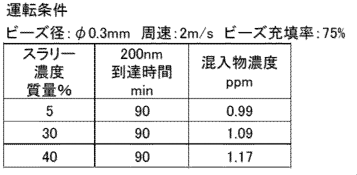
スラリー中のフェニトイン濃度を変化させても、200ナノメートルまでの粉砕時間はほぼ変化しなかった。また、ZY濃度も大きく変化しなかった。このように、40重量%以下の濃度では、スラリー濃度はZY濃度に影響しなかった。なお、50重量%の高濃度では、スラリーの流動性が悪化したが、粉砕処理は可能であった。
スラリー中のフェニトイン(原料粒度:16~20μm)の濃度を変えて、0.3mm径の部分安定化ジルコニアビーズを用い(ビーズ充填率:75%)、2m/秒の外周速にて、試験例1と同様に装置1にて粉砕処理した。200ナノメートルに到達するまでの粉砕処理時間と200nm到達時のスラリー中の混入物(ZY)濃度を下表に示す。
実施例1~31
図1~4に示したビーズミル(装置1~4)を用いて、各種有機物粒子(フェニトイン、スルファメトキサゾール、フェノフィブラート、メフェナム酸、イトラコナゾール)のスラリーを粉砕処理した。用いたビーズミル装置は以下のとおりである(下記のジルコニアはいずれも、添加物としてイットリウムを含む)。
装置1:Apex Mill 015型(広島メタル&マシナリー製)。接薬部の材質は、タングステンカーバイト、ニッケル(メカニカルシール)、ジルコニア入り強化アルミナ(ステーター)、ジルコニア(ローター)、パーフロ(Oリング)である。
装置2:Ultra Apex Mill 015型(広島メタル&マシナリー製)。接薬部の材質は、タングステンカーバイト、ニッケル(メカニカルシールUPPER側、LOWER側)、ジルコニア入り強化アルミナ(ステーター)、ジルコニア(セパレーター、ローター)、パーフロ(Oリング)である。
装置3:実験試作機。接薬部の材質は、ジルコニア入り強化アルミナ(ステーター)、ジルコニア(ローター)、SUS316L(ポンピング装置)、パーフロ(Oリング)である。
装置4:Dyno Mill リサーチラボ型[微小ビーズ対応小型湿式分散・粉砕機](シンマルエンタープライゼス製)。接薬部の材質は、ジルコニア(ハフニウムを含む)(アクセレレーター、ウェアーブッシュ)、SSiC(シリコン・カーバイド)(グランディングシリンダー)、ニッケル、ハードクロムメッキ(スクリーン)、バイトン(登録商標)(O-リング)である。
各実施例の粉砕処理の条件および結果を表3に示す。また、比較例として、強化アルミナ製ビーズを用いた比較例1、外周速またはビーズ径が本開示の条件の範囲外である比較例2~6を示す。混入物濃度は、ビーズ成分のジルコニウムとイットリウム、ビーズミルの容器の材質である強化アルミナの成分(アルミニウム)、ビーズミルで使用されている金属部材の主な成分である鉄、ニッケル、クロム、タングステンの濃度をそれぞれ記載した(粉砕処理したスラリー重量に対する質量ppmで表す)。
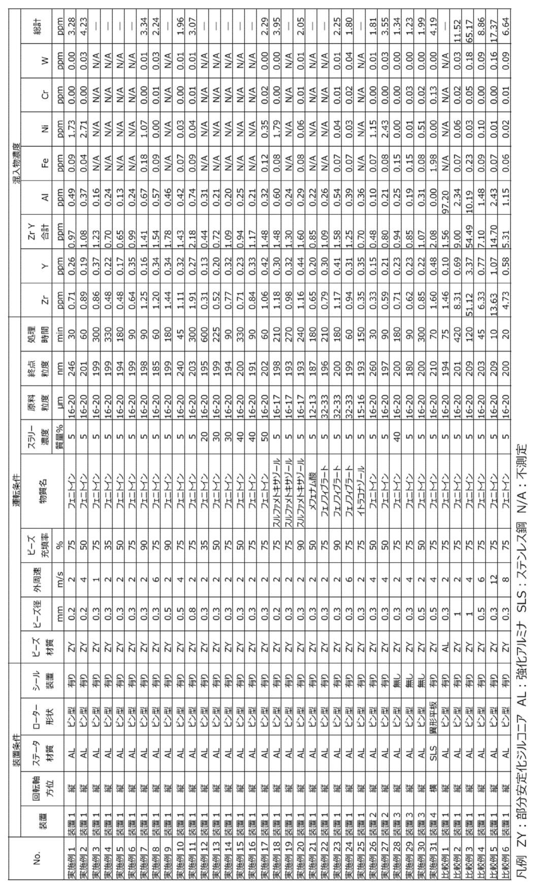
実施例1~25は、実効内容積150ミリリットルの装置1で、500グラムのスラリーを最終粒径200ナノメートル付近まで粉砕処理した結果である。スラリー中のZY濃度(表中「ZrY合計」の欄)は、いずれも5ppm以下であった。処理時間も工業的に適正な範囲であった。また、スラリー濃度が50重量%と高濃度であっても、処理時間の延長なく処理でき、ZY濃度も1.48ppmと低位であった(実施例17)。
実施例26と27は、実効内容積150ミリリットルの装置2で、フェニトインを粉砕処理した結果である。実施例26では、ZY濃度が0.48ppmと非常に低かった。
実施例28~30は、フェニトインをミル内の装置構成が装置1とほぼ同じである内容積150ミリリットルの装置3で処理した結果である。いずれの実施例でも、ZY濃度は低く(最大で1.07ppm)、処理時間も最長で300分間と適正な範囲であった。なお、装置3はメカニカルシールが設置されていないことから、ニッケル及びタングステンの濃度が、メカニカルシールを有する装置1を用いた場合(実施例1~25)と比べて低かった。このように、メカニカルシールが設置されていないビーズミルでは、金属部材からのスラリー中の重金属の混入物濃度を低減できる効果も認められた。
実施例31は装置4を用いて粉砕処理した結果である。装置4は横置きビーズミルであり、撹拌ローターは異形の板に穴が開いたものが複数設置されているものである。処理時間では、210ナノメートルまでの粉砕が70分間と問題なかった。混入物濃度では、ZY濃度が約2.1ppmであり、同一の運転条件にて装置1で処理した場合(実施例10の約1.4ppm)と比較すると高濃度であったが、十分に良好な結果であった。
一方、強化アルミナ製ビーズを用いて処理した比較例1では、スラリーへのアルミニウム混入が100ppm近くになっており、混入物濃度が極めて高かった。これは、強化アルミナは強度が高いが、じん性が低いため、摩耗が早く進んだためである。比較例2~6は装置1で部分安定化ジルコニアビーズを用いた処理ではあるが、外周速またはビーズ径が本開示の条件(0.15mm以上、且つ1.07-0.11×〔攪拌ローターの外周速度(m/秒)〕で計算される値(mm)以下)を外れている例である。比較例2~6はいずれも、ZY濃度が5ppmを超えており、最大値は約54.5ppmであった。
本開示は、医薬品・健康食品・X線造影剤などの有機物ナノ粒子の製造に適用できる。
1‥‥円筒
2‥‥上蓋
3‥‥下蓋
4‥‥回転軸
5‥‥撹拌ローター
6‥‥スラリー供給口
7‥‥スラリー排出口
8‥‥フラグ式ビーズ分離器
9‥‥回転軸プーリー
10‥‥ベルト
11‥‥モータープーリー
12‥‥モーター
13‥‥メカニカルシール
14‥‥遠心式ビーズ分離器
15‥‥スラリー貯槽
16‥‥連絡管路
17‥‥ポンピング装置
18‥‥スラリー配管
19‥‥スラリーポンプ
20‥‥スラリータンク
21‥‥撹拌装置
22‥‥スラリー連絡管
23‥‥スクリーン
2‥‥上蓋
3‥‥下蓋
4‥‥回転軸
5‥‥撹拌ローター
6‥‥スラリー供給口
7‥‥スラリー排出口
8‥‥フラグ式ビーズ分離器
9‥‥回転軸プーリー
10‥‥ベルト
11‥‥モータープーリー
12‥‥モーター
13‥‥メカニカルシール
14‥‥遠心式ビーズ分離器
15‥‥スラリー貯槽
16‥‥連絡管路
17‥‥ポンピング装置
18‥‥スラリー配管
19‥‥スラリーポンプ
20‥‥スラリータンク
21‥‥撹拌装置
22‥‥スラリー連絡管
23‥‥スクリーン
Claims (11)
- 湿式ビーズミルの容器内にて、有機物粒子を含むスラリーと、0.15~0.9mmの平均粒径を有するビーズとを含む混合物を、7m/秒以下の外周速度で回転する攪拌ローターにより攪拌する工程を含む、有機物ナノ粒子の製造方法。
- 湿式ビーズミルの容器内にて、有機物粒子を含むスラリーと、0.15mm以上、かつ1.07-0.11×〔攪拌ローターの外周速度(m/秒)〕で計算される値(mm)以下の平均粒径を有するビーズとを含む混合物を、7m/秒以下の外周速度で回転する攪拌ローターにより攪拌する工程を含む、有機物ナノ粒子の製造方法。
- ビーズが部分安定化ジルコニアからなる、請求項1または2に記載の製造方法。
- 湿式ビーズミルの容器内で、攪拌ローターを回転させる回転軸が鉛直方向に設置されている、請求項1~3のいずれかに記載の製造方法。
- 湿式ビーズミルの容器内にて、有機物粒子を含むスラリーとビーズとを含む混合物を攪拌ローターにより攪拌する工程を含む、有機物ナノ粒子の製造方法であって、該湿式ビーズミルの容器が縦型の円筒容器であり、該円筒容器の上部に開口部を備え、該攪拌ローターを回転させる回転軸が、該円筒容器の上方から該開口部を経由して該円筒容器内に挿入されており、該回転軸に該攪拌ローターが接続している、製造方法。
- 前記円筒容器の上方にスラリー貯槽があり、該円筒容器と該スラリー貯槽が連絡管路を介して連結しており、前記攪拌ローターを回転させる回転軸が、該スラリー貯槽の上方から該スラリー貯槽及び該連絡管路を経由して該円筒容器内に挿入されており、該回転軸に該攪拌ローターが接続しており、ビーズ分離処理後のスラリーが該円筒容器の下部から排出される、請求項5に記載の製造方法。
- 攪拌ローターが7m/秒以下の外周速度で回転する、請求項5または6に記載の製造方法。
- ビーズの平均粒径が0.15mm~0.9mmである、請求項5~7のいずれかに記載の製造方法。
- ビーズの平均粒径が0.15mm以上、かつ1.07-0.11×〔攪拌ローターの外周速度(m/秒)〕で計算される値(mm)以下である、請求項5~7のいずれかに記載の製造方法。
- ビーズが部分安定化ジルコニアからなる、請求項5~9のいずれかに記載の製造方法。
- 請求項1~10のいずれかに記載の製造方法によって得られる有機物ナノ粒子。
Priority Applications (4)
| Application Number | Priority Date | Filing Date | Title |
|---|---|---|---|
| EP20854349.6A EP4015086A4 (en) | 2019-08-16 | 2020-08-14 | METHOD FOR PRODUCING ORGANIC NANOPARTICLES AND ORGANIC NANOPARTICLES |
| JP2021540758A JPWO2021033633A1 (ja) | 2019-08-16 | 2020-08-14 | |
| US17/635,104 US20220287985A1 (en) | 2019-08-16 | 2020-08-14 | Organic nanoparticle production method and organic nanoparticles |
| JP2024185891A JP7690104B2 (ja) | 2019-08-16 | 2024-10-22 | 有機物ナノ粒子の製造方法及び有機物ナノ粒子 |
Applications Claiming Priority (2)
| Application Number | Priority Date | Filing Date | Title |
|---|---|---|---|
| JP2019149394 | 2019-08-16 | ||
| JP2019-149394 | 2019-08-16 |
Publications (2)
| Publication Number | Publication Date |
|---|---|
| WO2021033633A1 true WO2021033633A1 (ja) | 2021-02-25 |
| WO2021033633A8 WO2021033633A8 (ja) | 2021-07-29 |
Family
ID=74661074
Family Applications (1)
| Application Number | Title | Priority Date | Filing Date |
|---|---|---|---|
| PCT/JP2020/030862 Ceased WO2021033633A1 (ja) | 2019-08-16 | 2020-08-14 | 有機物ナノ粒子の製造方法及び有機物ナノ粒子 |
Country Status (4)
| Country | Link |
|---|---|
| US (1) | US20220287985A1 (ja) |
| EP (1) | EP4015086A4 (ja) |
| JP (2) | JPWO2021033633A1 (ja) |
| WO (1) | WO2021033633A1 (ja) |
Cited By (1)
| Publication number | Priority date | Publication date | Assignee | Title |
|---|---|---|---|---|
| US12285526B2 (en) | 2019-03-01 | 2025-04-29 | Shionogi & Co., Ltd. | Nanoparticle composition with reduced contaminant and production method thereof |
Citations (9)
| Publication number | Priority date | Publication date | Assignee | Title |
|---|---|---|---|---|
| JPH08501073A (ja) | 1992-06-10 | 1996-02-06 | イーストマン コダック カンパニー | 表面改質nsaidナノ粒子 |
| JPH1157514A (ja) * | 1997-06-13 | 1999-03-02 | Nippon Shokubai Co Ltd | ジルコニア系粉体の製造方法 |
| JP2003175341A (ja) | 1992-11-25 | 2003-06-24 | Elan Pharma Internatl Ltd | 診断画像形成剤及び薬物の粒子の製造方法 |
| JP2006212489A (ja) | 2005-02-01 | 2006-08-17 | Ashizawa Finetech Ltd | 媒体攪拌型粉砕装置を用いる粉砕方法 |
| JP2010510988A (ja) | 2006-11-28 | 2010-04-08 | マリナス ファーマシューティカルズ | ナノ粒子製剤とその製造方法およびその利用 |
| JP2011068544A (ja) * | 2008-12-11 | 2011-04-07 | Tosoh Corp | 表面が平滑なセラミックビーズおよびその製造方法 |
| WO2011059074A1 (ja) * | 2009-11-13 | 2011-05-19 | 森六ケミカルズ株式会社 | 微粉末の製造方法および同方法で製造された微粉末 |
| JP2016084294A (ja) | 2014-10-23 | 2016-05-19 | 富士フイルム株式会社 | エラグ酸分散組成物 |
| JP3222139U (ja) * | 2019-04-26 | 2019-07-11 | 株式会社広島メタル&マシナリー | ビーズミル |
Family Cites Families (8)
| Publication number | Priority date | Publication date | Assignee | Title |
|---|---|---|---|---|
| JP4763957B2 (ja) * | 2000-05-10 | 2011-08-31 | オバン・エナジー・リミテッド | メディアミリング |
| WO2012139895A1 (en) * | 2011-04-13 | 2012-10-18 | Dsm Ip Assets B.V. | Process for the manufacture of a powder containing lutein |
| US20150010652A1 (en) * | 2012-03-26 | 2015-01-08 | Kyowa Chemical Industry Co., Ltd. | Hydrotalcite fine particles |
| US10485785B2 (en) * | 2012-07-19 | 2019-11-26 | Moriroku Chemicals Company, Ltd. | Method for producing fine powder and the fine powder produced by the same |
| JP5995910B2 (ja) * | 2014-05-27 | 2016-09-21 | 紀州技研工業株式会社 | インクジェットインク及びその作製方法並びにインクジェットインクを用いた印字方法 |
| US20150343453A1 (en) * | 2014-05-28 | 2015-12-03 | NanoCentrix L.L.C. | Fluid energy media mill system and method |
| EP3612186A1 (en) * | 2017-04-18 | 2020-02-26 | Marinus Pharmaceuticals, Inc. | Sustained release injectable neurosteroid formulations |
| WO2020179701A1 (ja) * | 2019-03-01 | 2020-09-10 | 塩野義製薬株式会社 | 異物を低減したナノ粒子組成物およびその製法 |
-
2020
- 2020-08-14 EP EP20854349.6A patent/EP4015086A4/en active Pending
- 2020-08-14 US US17/635,104 patent/US20220287985A1/en active Pending
- 2020-08-14 WO PCT/JP2020/030862 patent/WO2021033633A1/ja not_active Ceased
- 2020-08-14 JP JP2021540758A patent/JPWO2021033633A1/ja active Pending
-
2024
- 2024-10-22 JP JP2024185891A patent/JP7690104B2/ja active Active
Patent Citations (9)
| Publication number | Priority date | Publication date | Assignee | Title |
|---|---|---|---|---|
| JPH08501073A (ja) | 1992-06-10 | 1996-02-06 | イーストマン コダック カンパニー | 表面改質nsaidナノ粒子 |
| JP2003175341A (ja) | 1992-11-25 | 2003-06-24 | Elan Pharma Internatl Ltd | 診断画像形成剤及び薬物の粒子の製造方法 |
| JPH1157514A (ja) * | 1997-06-13 | 1999-03-02 | Nippon Shokubai Co Ltd | ジルコニア系粉体の製造方法 |
| JP2006212489A (ja) | 2005-02-01 | 2006-08-17 | Ashizawa Finetech Ltd | 媒体攪拌型粉砕装置を用いる粉砕方法 |
| JP2010510988A (ja) | 2006-11-28 | 2010-04-08 | マリナス ファーマシューティカルズ | ナノ粒子製剤とその製造方法およびその利用 |
| JP2011068544A (ja) * | 2008-12-11 | 2011-04-07 | Tosoh Corp | 表面が平滑なセラミックビーズおよびその製造方法 |
| WO2011059074A1 (ja) * | 2009-11-13 | 2011-05-19 | 森六ケミカルズ株式会社 | 微粉末の製造方法および同方法で製造された微粉末 |
| JP2016084294A (ja) | 2014-10-23 | 2016-05-19 | 富士フイルム株式会社 | エラグ酸分散組成物 |
| JP3222139U (ja) * | 2019-04-26 | 2019-07-11 | 株式会社広島メタル&マシナリー | ビーズミル |
Non-Patent Citations (1)
| Title |
|---|
| See also references of EP4015086A4 |
Cited By (1)
| Publication number | Priority date | Publication date | Assignee | Title |
|---|---|---|---|---|
| US12285526B2 (en) | 2019-03-01 | 2025-04-29 | Shionogi & Co., Ltd. | Nanoparticle composition with reduced contaminant and production method thereof |
Also Published As
| Publication number | Publication date |
|---|---|
| JPWO2021033633A1 (ja) | 2021-02-25 |
| JP2025013919A (ja) | 2025-01-28 |
| WO2021033633A8 (ja) | 2021-07-29 |
| EP4015086A4 (en) | 2023-09-13 |
| EP4015086A1 (en) | 2022-06-22 |
| JP7690104B2 (ja) | 2025-06-09 |
| US20220287985A1 (en) | 2022-09-15 |
Similar Documents
| Publication | Publication Date | Title |
|---|---|---|
| JP5529884B2 (ja) | 微粉末の製造方法及び同方法で製造された微粉末 | |
| JP5144086B2 (ja) | 分散または粉砕装置及び分散または粉砕方法 | |
| EP2873453B1 (en) | Stirring method | |
| JP7602997B2 (ja) | 異物を低減したナノ粒子組成物およびその製法 | |
| JP5598824B2 (ja) | 分散または粉砕装置及び分散または粉砕方法 | |
| JP7690104B2 (ja) | 有機物ナノ粒子の製造方法及び有機物ナノ粒子 | |
| US10485785B2 (en) | Method for producing fine powder and the fine powder produced by the same | |
| CN203990334U (zh) | 一种悬浮液及胶体的制造装置 | |
| JP6423988B2 (ja) | 攪拌ミル及びスラリー中粒子の分散方法 | |
| CN105080376B (zh) | 一种悬浮液及胶体的制造方法和装置系统及应用 | |
| US20150343453A1 (en) | Fluid energy media mill system and method | |
| JP4073815B2 (ja) | 分散装置及び分散方法 | |
| JP2006212489A (ja) | 媒体攪拌型粉砕装置を用いる粉砕方法 | |
| JP2013039508A (ja) | メディア撹拌型粉砕機 | |
| JP7429039B2 (ja) | 湿式ビーズミル | |
| KR101245869B1 (ko) | 미디어 교반형 습식 분산기 | |
| JP3203625U (ja) | 攪拌ミル | |
| JP4956095B2 (ja) | メディア攪拌型湿式分散機 | |
| JP6779736B2 (ja) | スラリー中粒子の分散方法及び粉砕方法 | |
| JP4947470B2 (ja) | ナノ粒子スラリーの分散・凝集制御方法 | |
| JP2012179535A (ja) | 湿式媒体撹拌ミル | |
| JP3209743U (ja) | 攪拌ミル | |
| TWI755413B (zh) | 分散機與漿體中粒子的分散方法以及乳化製造方法 | |
| Miranda | Nanotechnology advancements and applications |
Legal Events
| Date | Code | Title | Description |
|---|---|---|---|
| 121 | Ep: the epo has been informed by wipo that ep was designated in this application |
Ref document number: 20854349 Country of ref document: EP Kind code of ref document: A1 |
|
| ENP | Entry into the national phase |
Ref document number: 2021540758 Country of ref document: JP Kind code of ref document: A |
|
| NENP | Non-entry into the national phase |
Ref country code: DE |
|
| ENP | Entry into the national phase |
Ref document number: 2020854349 Country of ref document: EP Effective date: 20220316 |