WO2021036470A1 - Compresseur et climatiseur - Google Patents
Compresseur et climatiseur Download PDFInfo
- Publication number
- WO2021036470A1 WO2021036470A1 PCT/CN2020/098699 CN2020098699W WO2021036470A1 WO 2021036470 A1 WO2021036470 A1 WO 2021036470A1 CN 2020098699 W CN2020098699 W CN 2020098699W WO 2021036470 A1 WO2021036470 A1 WO 2021036470A1
- Authority
- WO
- WIPO (PCT)
- Prior art keywords
- spool valve
- cavity
- valve
- compressor
- spool
- Prior art date
- Legal status (The legal status is an assumption and is not a legal conclusion. Google has not performed a legal analysis and makes no representation as to the accuracy of the status listed.)
- Ceased
Links
Images


Classifications
-
- F—MECHANICAL ENGINEERING; LIGHTING; HEATING; WEAPONS; BLASTING
- F04—POSITIVE - DISPLACEMENT MACHINES FOR LIQUIDS; PUMPS FOR LIQUIDS OR ELASTIC FLUIDS
- F04C—ROTARY-PISTON, OR OSCILLATING-PISTON, POSITIVE-DISPLACEMENT MACHINES FOR LIQUIDS; ROTARY-PISTON, OR OSCILLATING-PISTON, POSITIVE-DISPLACEMENT PUMPS
- F04C28/00—Control of, monitoring of, or safety arrangements for, pumps or pumping installations specially adapted for elastic fluids
- F04C28/10—Control of, monitoring of, or safety arrangements for, pumps or pumping installations specially adapted for elastic fluids characterised by changing the positions of the inlet or outlet openings with respect to the working chamber
- F04C28/12—Control of, monitoring of, or safety arrangements for, pumps or pumping installations specially adapted for elastic fluids characterised by changing the positions of the inlet or outlet openings with respect to the working chamber using sliding valves
-
- F—MECHANICAL ENGINEERING; LIGHTING; HEATING; WEAPONS; BLASTING
- F04—POSITIVE - DISPLACEMENT MACHINES FOR LIQUIDS; PUMPS FOR LIQUIDS OR ELASTIC FLUIDS
- F04C—ROTARY-PISTON, OR OSCILLATING-PISTON, POSITIVE-DISPLACEMENT MACHINES FOR LIQUIDS; ROTARY-PISTON, OR OSCILLATING-PISTON, POSITIVE-DISPLACEMENT PUMPS
- F04C28/00—Control of, monitoring of, or safety arrangements for, pumps or pumping installations specially adapted for elastic fluids
- F04C28/10—Control of, monitoring of, or safety arrangements for, pumps or pumping installations specially adapted for elastic fluids characterised by changing the positions of the inlet or outlet openings with respect to the working chamber
- F04C28/12—Control of, monitoring of, or safety arrangements for, pumps or pumping installations specially adapted for elastic fluids characterised by changing the positions of the inlet or outlet openings with respect to the working chamber using sliding valves
- F04C28/125—Control of, monitoring of, or safety arrangements for, pumps or pumping installations specially adapted for elastic fluids characterised by changing the positions of the inlet or outlet openings with respect to the working chamber using sliding valves with sliding valves controlled by the use of fluid other than the working fluid
Definitions
- This application relates to the technical field of compression equipment, in particular to a compressor and an air conditioner.
- Compressors are usually used in medium and large refrigeration systems. This type of system requires a wide range of load adjustments.
- the unit load can be adjusted by adjusting the compressor's flow rate.
- the spool valve mechanism changes the volume value at the end of suction to achieve suction. Changes in air flow.
- the compressor has an internal compression process.
- the ratio of the volume value at the end of suction to the volume value at the end of discharge is defined as the internal volume ratio VI, which directly determines the compressor pressure ratio PR (discharge pressure and suction pressure).
- PR discharge pressure and suction pressure
- the ratio of air pressure the two are in direct proportion, the internal volume ratio increases and the pressure ratio increases.
- the compressor cannot be adjusted adaptively, which reduces the efficiency of the compressor, which affects the use of the compressor.
- the problem is that a compressor and an air conditioner are proposed.
- the compressor can adjust the pressure ratio and flow rate adaptively according to the working conditions to improve the operating efficiency of the compressor; the air conditioner includes the above compressor, so the air conditioner is facing Under different working conditions, the heat exchange efficiency is high.
- the present application relates to a compressor, including: a compressor housing, the compressor housing is provided with a spool valve cavity; and a spool valve assembly, the spool valve assembly is arranged in the spool valve cavity, so
- the spool valve assembly includes a first spool valve and a second spool valve.
- the first spool valve is arranged at one end of the spool valve assembly, and the second spool valve is arranged at the other end of the spool valve assembly.
- the first spool valve and the second spool valve can move relative to the spool valve cavity so that the spool valve assembly includes a first working state and a second working state; when the spool valve assembly is in the first working state, so The first spool valve and the second spool valve are attached to and move synchronously; when the spool valve assembly is in the second working state, the first spool valve and the second spool valve separate and move relative to each other, and the The first spool valve and the second spool valve form a through hole communicating with the cavity where the rotor is installed.
- the first slide valve and the second slide valve are attached and move synchronously.
- the compressor is in a full load state.
- the first slide valve and the second slide valve move synchronously to adjust the pressure ratio of the compressor, so that when the compressor faces different working conditions, the pressure ratio of the compressor can be adjusted adaptively to improve the operating efficiency of the compressor;
- the valve assembly is in the second working state, the first spool valve and the second spool valve are separated, and the first spool valve and the second spool valve are spaced apart to form a through hole, and the through hole is connected to the supply
- the cavity where the rotor is installed is connected, which reduces the compressor flow rate and thus the load of the compressor.
- the compressor of the present application can adjust the pressure ratio of the compressor when the compressor is at full load, and at the same time, it can also adjust the flow of the compressor, so that the compressor is facing different operating conditions , Can maintain high operating efficiency.
- the slide valve assembly further includes an elastic reset member, one end of the elastic reset member is connected to one end of the first slide valve, and the other end of the elastic reset member is connected to the second slide valve. One end of the valve is connected.
- the slide valve assembly further includes an elastic reset member, one end of the elastic reset member is connected to one end of the first slide valve, and the other end of the elastic reset member is connected to the second slide valve. One end of the valve is connected.
- the other end of the first slide valve and the inner wall of the slide valve cavity form a first cavity
- the other end of the second slide valve is surrounded by the inner wall of the slide valve cavity.
- a second cavity is formed, the side wall of the first cavity is provided with a first supply channel for delivering the first pressure driving fluid to the first cavity, and the side wall of the second cavity is provided with a supply channel The second pressure driving fluid is delivered to the second supply channel in the second cavity.
- the compressor further includes a first valve body and a second valve body, the first valve body is used to control the conduction and closing of the first supply passage, and the second valve body is used for To control the on and off of the second supply channel.
- the side wall of the first cavity is further provided with a first unloading channel for unloading the first pressure driving fluid
- the side wall of the second cavity is provided with a first unloading channel for unloading the first The second unloading passage of the two pressure driving liquid.
- the number of the first unloading passages is at least two, and the first unloading passages are arranged at intervals along the moving direction of the first slide valve.
- the compressor further includes a third valve body and a fourth valve body, the third valve body is used to control the conduction and closing of the first unloading passage, and the fourth valve body is used for To control the on and off of the second unloading channel.
- the number of the second unloading passages is at least two, and the second unloading passages are arranged at intervals along the movement direction of the second slide valve.
- the volume of the first cavity or the second cavity is adjustable.
- the volumes of the first cavity and the second cavity are adjustable.
- the compressor housing includes a housing body, a first cover body, and a second cover body.
- the housing body is provided with a mounting cavity and a first opening and a second cover communicating with the mounting cavity. Two openings, a first cover body is telescopically arranged at the first opening, and the first cover body, the first slide valve and the inner wall of the installation cavity enclose the first cavity, the The second cover body is telescopically arranged at the second opening, and the second cover body, the second slide valve and the inner wall of the installation cavity surround the second cavity.
- the inner wall of the first opening is provided with a first internal thread structure, and the first cover is threadedly connected with the first internal thread structure; or the inner wall of the second opening is provided with A second internal thread structure, the second cover body is threadedly connected with the second internal thread structure.
- the inner wall of the first opening is provided with a first internal thread structure, and the first cover is threadedly connected with the first internal thread structure; the inner wall of the second opening is provided with a first internal thread structure.
- the present application also relates to an air conditioner, including the compressor in any of the above embodiments.
- the slide valve assembly When the above air conditioner is in use, when the slide valve assembly is in the first working state, the first slide valve and the second slide valve are attached and move synchronously. At this time, the compressor is in a full load state and passes through the first A spool valve and a second spool valve move synchronously to adjust the pressure ratio of the compressor, so that the compressor can adjust the pressure ratio of the compressor adaptively when facing different working conditions, and improve the operating efficiency of the compressor;
- the assembly When the assembly is in the second working state, the first spool valve and the second spool valve are separated, and the first spool valve and the second spool valve are spaced apart to form a through hole. Assuming that the cavity of the rotor is connected, the compressor flow rate is reduced and the load of the compressor is reduced.
- the compressor of the present application can adjust the pressure ratio of the compressor when the compressor is at full load, and at the same time, it can also adjust the flow of the compressor, so that the compressor can be Maintain high operating efficiency.
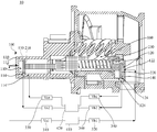
- Figure 1 is a schematic diagram of the structure of a compressor in an embodiment
- Figure 2 is a schematic structural diagram of a compressor in another embodiment
- Fig. 3 is a schematic diagram of the structure of the compressor in another embodiment.
- Compressor 100, compressor housing; 110, first cavity; 112, first supply channel; 114, first unloading channel; 120, second cavity; 122, second supply channel; 124, first Two unloading passage; 130, the first cover; 140, the second cover; 150, the housing body; 160, the through hole; 210, the first slide valve; 220, the second slide valve; 230, the elastic reset part; 310 , The first valve body; 320, the second valve body; 330, the third valve body; 340, the fourth valve body; 410, high-pressure oil device; 420, low-pressure unloading device.
- a compressor 10 in an embodiment includes: a compressor housing 100 and a slide valve assembly.
- the compressor housing 100 is provided with a slide valve cavity; the slide valve assembly is disposed on the slide valve.
- the spool valve assembly includes a first spool valve 210 and a second spool valve 220.
- the first spool valve 210 is arranged at one end of the spool valve assembly, and the second spool valve 220 is arranged at the other end of the spool valve assembly.
- the spool valve assembly 210 and the second spool valve 220 can move relative to the spool valve cavity so that the spool valve assembly includes a first working state and a second working state; when the spool valve assembly is in the first working state, the first spool valve 210 and the second spool valve 220 When the spool valve assembly is in the second working state, the first spool valve 210 and the second spool valve 220 separate and move relative to each other, and the first spool valve 210 and the second spool valve 220 form a connection for installing the rotor
- the cavity 160 communicates with the through hole.
- the compressor 10 When the above-mentioned compressor 10 is in use, when the slide valve assembly is in the first working state, the first slide valve 210 and the second slide valve 220 are aligned and move synchronously. There is no bypass orifice inside the compressor 10, and the maximum flow rate is always maintained. When the compressor 10 is running, the compressor 10 is at full load. The pressure ratio of the compressor 10 is adjusted by the synchronous movement of the first slide valve 210 and the second slide valve 220, so that the compressor 10 can be adjusted adaptively when facing different working conditions.
- the pressure ratio of the compressor 10 improves the operating efficiency of the compressor 10; when the spool valve assembly is in the second working state, the first spool valve 210 and the second spool valve 220 are separated, and the first spool valve 210 and the second spool valve 220 A through hole 160 is formed at intervals.
- the through hole 160 communicates with the cavity in which the rotor is installed, so that the compressor flow rate is reduced and the load of the compressor 10 is reduced.
- the compressor of the present application 10 can adjust the pressure ratio of the compressor 10 when the compressor 10 is at full load, and can also adjust the flow rate of the compressor 10, so that the compressor 10 can maintain a high operating efficiency when facing different working conditions .
- the slide valve assembly further includes an elastic reset member 230.
- One end of the elastic reset member 230 is connected to one end of the first slide valve 210, and the other end of the elastic reset member 230 is connected to the second slide valve 210.
- One end of the spool valve 220 is connected.
- the first spool valve 210 and the second spool valve 220 are stressed and squeeze the elastic reset member 230 to make the first spool valve 210 and the second spool valve 220 Attach and move synchronously; when the spool valve assembly is in the second working state, the elastic reset member 230 pushes the first spool valve 210 and/or the second spool valve 220 to separate the first spool valve 210 and the second spool valve 220 and move relatively In this way, by applying pressure to the first spool valve 210 and pressure to the second spool valve 220, the first spool valve 210 and the second spool valve 220 move towards each other until they are in contact with each other.
- the compressor 10 is at full load. ;
- the pressure ratio of the compressor can be adjusted, and the pressure ratio of the compressor can be adjusted when the compressor 10 is in a full state;
- the external force is When the external force exerted by the first spool valve 210 and/or the external force on the second spool valve 220 is less than the elastic force of the elastic resetting member 230, at this time, under the action of the elastic resetting member 230, the elastic resetting member 230 pushes the first spool valve 210 and/or Or the second spool valve 220 separates the first spool valve 210 and the second spool valve 220 and moves relative to each other.
- a through hole 160 is formed between the first spool valve 210 and the second spool valve 220, and the compressor flow rate is reduced.
- the load of the compressor 10 is reduced. Due to the relative movement of the first slide valve 210 and the second slide valve 220, the size of the through hole 160 becomes larger or smaller, so that the compressor flow rate and load can be adjusted.
- the elastic reset member 230 may be a spring, an elastic rubber strip, or the like.
- the movement of the first spool valve 210 and the second spool valve 220 can be driven by a corresponding drive mechanism, of course, can also be driven by a pressure-driven liquid, as shown in Figures 1 to 3, in this implementation
- the other end of the first spool valve 210 and the inner wall of the spool valve cavity form a first cavity 110
- the other end of the second spool valve 220 and the inner wall of the spool valve cavity form a second cavity 120.
- the side wall of a cavity 110 is provided with a first supply channel 112 for delivering the first pressure driving fluid to the first cavity 110. At this time, the first pressure driving is delivered to the first cavity 110 through the first supply channel 112.
- the first spool valve 210 is moved by applying pressure to the first spool valve 210 by the first pressure driving fluid.
- the side wall of the second cavity 120 is provided with a second pressure driving fluid for delivering the second pressure driving fluid to the second cavity 120.
- the second pressure driving fluid is delivered to the second cavity 120 through the second supply passage 122, and the second pressure driving fluid applies pressure to the second spool valve 220 to make the second spool valve 220 mobile.
- the first pressure driving liquid and the second pressure driving liquid may be high-pressure oil.
- first cavity 110 or the second cavity 120 may be provided with an elastic reset member 230 correspondingly, and the first spool valve 210 and the second spool valve 220 can be separated by high-pressure oil in cooperation with the elastic reset member. And fit.
- the compressor 10 further includes a first valve body 310 and a second valve body 320.
- the first valve body 310 is used to control the conduction of the first supply passage 112.
- the second valve body 320 is used to control the on and off of the second supply channel 122.
- the first valve body 310 and the second valve body 320 can be battery valves; in this embodiment, the A valve body 310 is arranged on the first pipe connecting the first supply passage 112 and the first liquid supply device, and the second valve body 320 is arranged on the second pipe connecting the second supply passage 122 and the second liquid supply device.
- the first liquid supply device and the second liquid supply device may be the same or different.
- the side wall of the first cavity 110 is also provided with a first unloading channel 114 for unloading the first pressure driving liquid
- the side wall of the second cavity 120 is provided with The second unloading passage 124 for unloading the second pressure driving liquid.
- the first pressure driving fluid in the first cavity 110 is unloaded through the first unloading passage 114, thereby reducing the pressure in the first cavity 110; in the same way, the second cavity 120 is unloaded through the second unloading passage 124
- the second pressure inside drives the liquid to unload, thereby reducing the pressure in the second cavity 120.
- the compressor 10 further includes a third valve body 330 and a fourth valve body 340.
- the third valve body 330 is used to control the conduction and closing of the first unloading passage 114, and the fourth valve body 340 is used to control the on and off of the second unloading passage 124.
- the third valve body 330 and the fourth valve body 340 can be battery valves; in this embodiment, the third valve body 330 is disposed on the third pipe connecting the first unloading passage 114 and the first unloading device, The fourth valve body 340 is disposed on a fourth pipe connecting the second unloading passage 124 and the second unloading device.
- the first unloading device and the second unloading device may be the same or different.
- the self-pressure of the first pressure-driving liquid and the self-pressure of the second pressure-driving liquid may be different.
- the first spool valve 210 is driven to move by the first pressure-driving liquid
- the second spool valve 220 is driven by the second pressure-driving liquid.
- the movement makes the first spool valve 210 and the second spool valve 220 fit together.
- the first spool valve 210 and the second spool valve 220 are different It moves in the direction of the compressor 10 to adjust the pressure ratio of the compressor 10 when the compressor 10 is at full load.
- the self-pressure of the first pressure-driving liquid and the self-pressure of the second pressure-driving liquid can also be the same.
- the first valve body 310 and the third valve body can be opened and closed.
- the second pressure in the second cavity 120 can be adjusted by opening and closing the second valve body 320 and the fourth valve body 340
- the first spool valve 210 and the second spool valve 220 move to fit and the first spool valve 210 and the second spool valve 220 move in the direction of squeezing the first cavity 110 at the same time.
- the pressure ratio of the compressor 10 is increased; when the second pressure driving liquid in the second cavity 120 exerts a pressure on the second slide valve 220 less than the pressure in the first cavity 110
- the first pressure driving fluid exerts pressure on the first spool valve 210
- the first spool valve 210 and the second spool valve 220 move to fit and the first spool valve 210 and the second spool valve 220 simultaneously squeeze the second cavity Moving in the direction of the body 120, when the compressor 10 is at full load, the pressure ratio of the compressor 10 can be reduced.
- the third valve body 330 is opened to unload the pressure in the first cavity 110.
- the first spool valve 210 and the second spool valve 220 can Synchronously move to the outlet position of the first unloading passage 114, so that the compressor 10 has a pressure ratio, that is, by fixing the outlet position of the first unloading passage 114, the corresponding pressure ratio of the compressor 10 can be indicated;
- the number of first unloading passages 114 is at least two, and the first unloading passages 114 are arranged at intervals along the moving direction of the first slide valve 210.
- the number of the first unloading passages 114 corresponds to one compressor 10 pressure ratio, so at least two first unloading passages 114 can be provided to indicate the pressure ratio of the two compressors. At this time, the inlet position of the first unloading passage 114 indicates the compressor 10 pressure ratio. At a larger position, because the pressure ratio of the compressor gradually increases toward the direction of squeezing the first cavity 110.
- the number of the second unloading passage 124 of the compressor 10 is at least two, and the second unloading passage 124 is along the moving direction of the second slide valve 220 At this time, the inlet position of each second unloading passage 124 corresponds to a pressure ratio of the compressor 10. Therefore, setting at least two second unloading passages 124 can indicate the pressure ratio of the two compressors. At this time, the second unloading passage 124 The inlet position of the passage 124 indicates the position where the pressure of the compressor 10 is relatively low, because the pressure ratio of the compressor gradually decreases toward the direction of squeezing the second cavity 120.
- the first spool valve 210 and the second spool valve 220 are separated under the action of the elastic reset member 230, and the through hole 160 formed between the first spool valve 210 and the second spool valve 220 gradually increases, so that the compressor 10 can be adjusted. Of traffic.
- both the first pressure driving fluid and the second pressure driving fluid are high-pressure lubricating oil, and the first supply liquid
- the device and the second liquid supply device are the same high-pressure oil device 410 and the high-pressure oil device 410 is provided with a high-pressure cavity, and the first unloading device and the second unloading device are the same low-pressure unloading device 420 with a low-pressure cavity inside.
- the outlet of the first supply channel 112 is arranged on the bottom wall of the first cavity 110, the number of the third valve body 330 is at least two, one of the third valve bodies 330 is marked as Va2, and the other third valve bodies 330
- the first valve body 310 is marked as Van, and the first valve body 310 is marked as Va1, where Va2 (the third valve body 330) corresponds to the control of the first unloading passage 114 compared to the other Van (the third valve body 330) corresponding to the control of the first unloading passage
- the inlet of 114 is closer to the outlet of the first supply passage 112; the outlet of the second supply passage 122 is arranged on the bottom wall of the second cavity 120, the number of the fourth valve body 340 is at least two, of which one fourth valve body 340 It is marked as Vb2, the remaining fourth valve body 340 is marked as Vbn, and the second valve body 320 is marked as Vb1, where Vb2 corresponds to the inlet of the second unloading passage 124 controlled by the
- Vb1 (the second valve body 320) is open, Vb2 (the fourth valve body 340) is closed, Va1 (the first valve body 310) is closed, and Va2 (the third valve body 330) is closed.
- high-pressure lubricating oil enters the second cavity 120 to push the first slide valve 210 and the second slide valve 220 to move together, and the exhaust is delayed.
- the pressure ratio of the compressor 10 increases; when the second slide valve 220 moves To the leftmost limit position (it is necessary to point out that the leftmost limit position can be set according to the pressure ratio.
- the leftmost limit position is Va2 (third valve body 330) corresponding to the control
- Va1 the first valve body 310
- Va1 the first valve body 310
- the pressure ratio of the compressor 10 is adjusted to the maximum.
- the number of second unloading passages 124 is at least two, and they are arranged at intervals along the axial direction of the second cavity 120.
- the compressor 10 is at the maximum pressure ratio, one The second unloading passage 124 whose inlet is located in the middle of the second cavity 120, when the Vbn (fourth valve body 340) that controls the second unloading passage 124 is opened, and Va1 (first valve body 310) is kept open, the first slide valve 210 and the second slide valve 220 move together to the middle position (that is, the inlet position of the second unloading passage 124), and the compressor 10 is adjusted to the middle pressure ratio at this time.
- Vb1 second valve body 320
- Vb2 fourth valve body 340
- the second slide valve 220 is retracted to the maximum stroke under the force of the elastic reset member 230 and remains stationary;
- Va1 first valve body 310
- first valve body 310 moves to the left to the corresponding position (that is, the first unloading passage 114 controlled by Van (third valve body 330) Inlet position).
- the first slide valve 210 and the second slide valve 220 are separated and arranged at intervals to form a through hole 160, and the compressor 10 is adjusted to a partial load, that is, the flow rate of the compressor 10 is adjusted.
- the first spool valve 210 and the second spool valve 220 can be reset to both sides when the machine is stopped, and no-load start can be realized with a small starting current ,
- the starting power consumption is low; during the starting process Va1 (first valve body 310) is opened, Va2 (third valve body 330) and Van (third valve body 330) are closed, Vb1 (second valve body 320) is closed, and Vb2 (first valve body 320) is closed.
- the three valve body 330) is opened, and the high pressure oil drives the first spool valve 210 to move to the right.
- the compressor 10 When the first spool valve 210 is attached to the second spool valve 220, the compressor 10 reaches a full load state. At this time, the second spool valve 220 is moved to the rightmost side of the second cavity 120 (the specific position is provided with a corresponding limit part according to needs. In this embodiment, it is the position that abuts the second cover 140, and the second cover 140 restricts the With the movement of the second slide valve 220, the compressor 10 is at the minimum pressure ratio at this time.
- the compressor housing 100 includes a housing body 150, a first cover 130 and a second cover 140, the housing body 150 is provided with a mounting cavity and a first opening and a first opening communicating with the mounting cavity Two openings, the first cover 130 is telescopically disposed in the first opening, and the first cover 130, the first slide valve 210 and the inner wall of the installation cavity enclose the first cavity 110, and the second cover 140 is telescopic Is arranged in the second opening, and the second cover 140, the second slide valve 220 and the inner wall of the installation cavity enclose the second cavity 120.
- the size of the first cavity 110 can be adjusted by adjusting the first cover 130 by telescoping.
- the second cover 140 is adjusted telescopically to adjust the size of the second cavity 120.
- the inner wall of the first opening is provided with a first internal thread structure
- the first cover 130 is threadedly connected with the first internal thread structure
- the inner wall of the second opening is provided with a second internal thread structure
- the second cover 140 is threadedly connected with the second internal thread structure, so that the first cavity 110 and/or the first cavity 110 and/or are adjusted by the threaded connection of the first cover 130 and/or the second cover 140 and the housing body 150 Or the size of the second cavity 120.
- the compressor flow refers to the actual suction volume flow of the compressor in m 3 /h; the compressor load refers to the current actual suction volume flow of the compressor and the current maximum suction volume flow that can be reached.
- the unit is 100%.
- an embodiment also relates to an air conditioner, including the compressor 10 in any of the above embodiments.
- the slide valve assembly when the slide valve assembly is in the first working state, the first slide valve 210 and the second slide valve 220 are attached and move synchronously. At this time, the compressor 10 is in a full load state and passes through the first slide valve 210 and the second slide valve 220.
- the second slide valve 220 moves synchronously to adjust the pressure ratio of the compressor 10, so that the compressor 10 can adjust the pressure ratio of the compressor 10 adaptively when facing different working conditions, and improve the operating efficiency of the compressor 10; when the slide valve assembly In the second working state, the first spool valve 210 and the second spool valve 220 are separated, and a through hole 160 is formed between the first spool valve 210 and the second spool valve 220.
- the communication of the cavity reduces the compressor flow rate and thus the load of the compressor 10.
- the size of the through hole 160 becomes larger or smaller, so that the compressor flow and load can be adjusted
- the compressor 10 of the present application can adjust the pressure ratio of the compressor 10 when the compressor 10 is at full load, and can also adjust the flow rate of the compressor 10, so that the compressor 10 faces different operating conditions , Can maintain high operating efficiency.
Landscapes
- Engineering & Computer Science (AREA)
- Mechanical Engineering (AREA)
- General Engineering & Computer Science (AREA)
- Applications Or Details Of Rotary Compressors (AREA)
- Multiple-Way Valves (AREA)
- Compressor (AREA)
Abstract
L'invention concerne un compresseur (10), comprenant : un carter de compresseur (100), lequel est pourvu d'une cavité de distributeur à tiroir ; et un ensemble de distributeurs à tiroir, lequel est disposé à l'intérieur de la cavité de distributeur à tiroir, l'ensemble de distributeurs à tiroir comprenant un premier distributeur à tiroir (210) et un deuxième distributeur à tiroir (220). Le premier distributeur à tiroir (210) est disposé à une extrémité de l'ensemble de distributeurs à tiroir, le deuxième distributeur à tiroir (220) est disposé à l'autre extrémité de l'ensemble de distributeurs à tiroir, et le premier distributeur à tiroir (210) et le deuxième distributeur à tiroir (220) peuvent se déplacer par rapport à la cavité de distributeur à tiroir, de sorte que l'ensemble de distributeurs à tiroir comprend un premier état de fonctionnement et un deuxième état de fonctionnement. Lorsque l'ensemble de distributeurs à tiroir se trouve dans le premier état de fonctionnement, le premier distributeur à tiroir (210) et le deuxième distributeur à tiroir (220) sont attachés et se déplacent de manière synchrone, et lorsque l'ensemble de distributeurs à tiroir se trouve dans le deuxième état de fonctionnement, le premier distributeur à tiroir (210) et le deuxième distributeur à tiroir (220) sont séparés et se déplacent l'un par rapport à l'autre, et le premier distributeur à tiroir (210) et le deuxième distributeur à tiroir (220) forment un trou traversant (160) en communication avec une cavité destinée au montage d'un rotor. L'invention concerne également un climatiseur comprenant le compresseur (10).
Applications Claiming Priority (2)
| Application Number | Priority Date | Filing Date | Title |
|---|---|---|---|
| CN201910791574.8A CN110410329B (zh) | 2019-08-26 | 2019-08-26 | 压缩机及空调 |
| CN201910791574.8 | 2019-08-26 |
Publications (1)
| Publication Number | Publication Date |
|---|---|
| WO2021036470A1 true WO2021036470A1 (fr) | 2021-03-04 |
Family
ID=68368653
Family Applications (1)
| Application Number | Title | Priority Date | Filing Date |
|---|---|---|---|
| PCT/CN2020/098699 Ceased WO2021036470A1 (fr) | 2019-08-26 | 2020-06-29 | Compresseur et climatiseur |
Country Status (2)
| Country | Link |
|---|---|
| CN (1) | CN110410329B (fr) |
| WO (1) | WO2021036470A1 (fr) |
Families Citing this family (2)
| Publication number | Priority date | Publication date | Assignee | Title |
|---|---|---|---|---|
| CN110410329B (zh) * | 2019-08-26 | 2025-06-27 | 珠海格力电器股份有限公司 | 压缩机及空调 |
| CN117432619A (zh) * | 2022-07-15 | 2024-01-23 | 青岛海尔空调电子有限公司 | 用于控制压缩机的方法及装置、压缩机 |
Citations (12)
| Publication number | Priority date | Publication date | Assignee | Title |
|---|---|---|---|---|
| US5044894A (en) * | 1990-11-30 | 1991-09-03 | Carrier Corporation | Capacity volume ratio control for twin screw compressors |
| JP2005264791A (ja) * | 2004-03-17 | 2005-09-29 | Hitachi Ltd | 2段スクリュー圧縮機および冷凍装置 |
| US20060008375A1 (en) * | 2004-07-12 | 2006-01-12 | Kabushiki Kaisha Kobe Seiko Sho (Kobe Steel, Ltd.) | Screw compressor |
| CN202040084U (zh) * | 2010-10-29 | 2011-11-16 | 武汉新世界制冷工业有限公司 | 油缸内置型螺杆压缩机能量和内容积比调节机构 |
| CN103857915A (zh) * | 2012-10-11 | 2014-06-11 | 江森自控科技公司 | 用于螺旋压缩机的手动容积比调节机构 |
| CN104421157A (zh) * | 2013-08-27 | 2015-03-18 | 珠海格力节能环保制冷技术研究中心有限公司 | 压缩机及其滑阀装置 |
| CN104500399A (zh) * | 2014-09-15 | 2015-04-08 | 汉钟精机股份有限公司 | 压缩机滑阀位置控制的结构 |
| CN204755308U (zh) * | 2015-07-30 | 2015-11-11 | 烟台荏原空调设备有限公司 | 一种螺杆式制冷系统及其螺杆式压缩机 |
| CN106468262A (zh) * | 2016-08-25 | 2017-03-01 | 北京工业大学 | 单螺杆压缩机复合滑阀系统 |
| CN206636871U (zh) * | 2017-04-07 | 2017-11-14 | 佛山市高明康得球铁有限公司 | 可调行程止转油缸 |
| CN110410329A (zh) * | 2019-08-26 | 2019-11-05 | 珠海格力电器股份有限公司 | 压缩机及空调 |
| CN210423025U (zh) * | 2019-08-26 | 2020-04-28 | 珠海格力电器股份有限公司 | 压缩机及空调 |
Family Cites Families (2)
| Publication number | Priority date | Publication date | Assignee | Title |
|---|---|---|---|---|
| CN203257684U (zh) * | 2012-12-26 | 2013-10-30 | 福建雪人压缩机科技有限公司 | 一种组合式螺杆压缩机能量及内容积比滑阀调节机构 |
| RU2713784C1 (ru) * | 2016-04-06 | 2020-02-07 | Битцер Кюльмашиненбау Гмбх | Винтовой компрессор (варианты) |
-
2019
- 2019-08-26 CN CN201910791574.8A patent/CN110410329B/zh active Active
-
2020
- 2020-06-29 WO PCT/CN2020/098699 patent/WO2021036470A1/fr not_active Ceased
Patent Citations (12)
| Publication number | Priority date | Publication date | Assignee | Title |
|---|---|---|---|---|
| US5044894A (en) * | 1990-11-30 | 1991-09-03 | Carrier Corporation | Capacity volume ratio control for twin screw compressors |
| JP2005264791A (ja) * | 2004-03-17 | 2005-09-29 | Hitachi Ltd | 2段スクリュー圧縮機および冷凍装置 |
| US20060008375A1 (en) * | 2004-07-12 | 2006-01-12 | Kabushiki Kaisha Kobe Seiko Sho (Kobe Steel, Ltd.) | Screw compressor |
| CN202040084U (zh) * | 2010-10-29 | 2011-11-16 | 武汉新世界制冷工业有限公司 | 油缸内置型螺杆压缩机能量和内容积比调节机构 |
| CN103857915A (zh) * | 2012-10-11 | 2014-06-11 | 江森自控科技公司 | 用于螺旋压缩机的手动容积比调节机构 |
| CN104421157A (zh) * | 2013-08-27 | 2015-03-18 | 珠海格力节能环保制冷技术研究中心有限公司 | 压缩机及其滑阀装置 |
| CN104500399A (zh) * | 2014-09-15 | 2015-04-08 | 汉钟精机股份有限公司 | 压缩机滑阀位置控制的结构 |
| CN204755308U (zh) * | 2015-07-30 | 2015-11-11 | 烟台荏原空调设备有限公司 | 一种螺杆式制冷系统及其螺杆式压缩机 |
| CN106468262A (zh) * | 2016-08-25 | 2017-03-01 | 北京工业大学 | 单螺杆压缩机复合滑阀系统 |
| CN206636871U (zh) * | 2017-04-07 | 2017-11-14 | 佛山市高明康得球铁有限公司 | 可调行程止转油缸 |
| CN110410329A (zh) * | 2019-08-26 | 2019-11-05 | 珠海格力电器股份有限公司 | 压缩机及空调 |
| CN210423025U (zh) * | 2019-08-26 | 2020-04-28 | 珠海格力电器股份有限公司 | 压缩机及空调 |
Also Published As
| Publication number | Publication date |
|---|---|
| CN110410329A (zh) | 2019-11-05 |
| CN110410329B (zh) | 2025-06-27 |
Similar Documents
| Publication | Publication Date | Title |
|---|---|---|
| CN108980014B (zh) | 活塞式压缩机的气缸座组件、活塞式压缩机及制冷系统 | |
| CN102889397B (zh) | 节能阀 | |
| CN103162477B (zh) | 组合阀 | |
| CN106322860A (zh) | 一种空调器用卸荷阀组件及空调器 | |
| WO2021036470A1 (fr) | Compresseur et climatiseur | |
| CN106641361B (zh) | 一种自适应节流阀、空调系统 | |
| CN104912795A (zh) | 变容量涡旋压缩机 | |
| CN112049769A (zh) | 活塞压缩机和制冷设备 | |
| CN210423025U (zh) | 压缩机及空调 | |
| CN101846201A (zh) | 二氧化碳汽车空调系统膨胀阀 | |
| CN110439785B (zh) | 滑阀组件、压缩机及制冷装置 | |
| CN105378394B (zh) | 制冷设备的压缩机和包括所述压缩机的制冷设备 | |
| CN105650780A (zh) | 一种汽车电动热泵空调系统 | |
| CN211259008U (zh) | 双级压缩机及空调机组 | |
| CN107989768A (zh) | 压缩机以及制冷装置 | |
| CN107191375A (zh) | 压缩机构和制冷设备 | |
| CN110454365A (zh) | 压缩机及具有其的制冷设备 | |
| CN217355673U (zh) | 组合阀及排量调节系统 | |
| CN103649558B (zh) | 用于控制液压气动的压力传送装置的阀和具有阀的液压气动的压力传送装置 | |
| CN207004822U (zh) | 压缩机构和制冷设备 | |
| CN110553431B (zh) | 一种分液器、包括该分液器的压缩机及空调器 | |
| CN209910227U (zh) | 一种节流装置及空调器 | |
| CN210949142U (zh) | 泵体组件、压缩机及空调器 | |
| CN110017395B (zh) | 一种可变排量压缩机用外控阀 | |
| CN204200522U (zh) | 一种集成阀及压缩机 |
Legal Events
| Date | Code | Title | Description |
|---|---|---|---|
| 121 | Ep: the epo has been informed by wipo that ep was designated in this application |
Ref document number: 20856474 Country of ref document: EP Kind code of ref document: A1 |
|
| NENP | Non-entry into the national phase |
Ref country code: DE |
|
| 122 | Ep: pct application non-entry in european phase |
Ref document number: 20856474 Country of ref document: EP Kind code of ref document: A1 |