WO2021039989A1 - リーン車両 - Google Patents
リーン車両 Download PDFInfo
- Publication number
- WO2021039989A1 WO2021039989A1 PCT/JP2020/032675 JP2020032675W WO2021039989A1 WO 2021039989 A1 WO2021039989 A1 WO 2021039989A1 JP 2020032675 W JP2020032675 W JP 2020032675W WO 2021039989 A1 WO2021039989 A1 WO 2021039989A1
- Authority
- WO
- WIPO (PCT)
- Prior art keywords
- lean vehicle
- body frame
- main skeleton
- vehicle body
- vehicle
- Prior art date
- Legal status (The legal status is an assumption and is not a legal conclusion. Google has not performed a legal analysis and makes no representation as to the accuracy of the status listed.)
- Ceased
Links
Images


Classifications
-
- B—PERFORMING OPERATIONS; TRANSPORTING
- B62—LAND VEHICLES FOR TRAVELLING OTHERWISE THAN ON RAILS
- B62K—CYCLES; CYCLE FRAMES; CYCLE STEERING DEVICES; RIDER-OPERATED TERMINAL CONTROLS SPECIALLY ADAPTED FOR CYCLES; CYCLE AXLE SUSPENSIONS; CYCLE SIDE-CARS, FORECARS, OR THE LIKE
- B62K5/00—Cycles with handlebars, equipped with three or more main road wheels
- B62K5/10—Cycles with handlebars, equipped with three or more main road wheels with means for inwardly inclining the vehicle body on bends
-
- B—PERFORMING OPERATIONS; TRANSPORTING
- B62—LAND VEHICLES FOR TRAVELLING OTHERWISE THAN ON RAILS
- B62J—CYCLE SADDLES OR SEATS; AUXILIARY DEVICES OR ACCESSORIES SPECIALLY ADAPTED TO CYCLES AND NOT OTHERWISE PROVIDED FOR, e.g. ARTICLE CARRIERS OR CYCLE PROTECTORS
- B62J17/00—Weather guards for riders; Fairings or stream-lining parts not otherwise provided for
- B62J17/08—Hoods protecting the rider
- B62J17/086—Frame mounted hoods specially adapted for motorcycles or the like
-
- B—PERFORMING OPERATIONS; TRANSPORTING
- B62—LAND VEHICLES FOR TRAVELLING OTHERWISE THAN ON RAILS
- B62J—CYCLE SADDLES OR SEATS; AUXILIARY DEVICES OR ACCESSORIES SPECIALLY ADAPTED TO CYCLES AND NOT OTHERWISE PROVIDED FOR, e.g. ARTICLE CARRIERS OR CYCLE PROTECTORS
- B62J25/00—Foot-rests; Knee grips; Passenger hand-grips
- B62J25/04—Floor-type foot rests
-
- B—PERFORMING OPERATIONS; TRANSPORTING
- B62—LAND VEHICLES FOR TRAVELLING OTHERWISE THAN ON RAILS
- B62K—CYCLES; CYCLE FRAMES; CYCLE STEERING DEVICES; RIDER-OPERATED TERMINAL CONTROLS SPECIALLY ADAPTED FOR CYCLES; CYCLE AXLE SUSPENSIONS; CYCLE SIDE-CARS, FORECARS, OR THE LIKE
- B62K5/00—Cycles with handlebars, equipped with three or more main road wheels
- B62K5/02—Tricycles
- B62K5/05—Tricycles characterised by a single rear wheel
-
- B—PERFORMING OPERATIONS; TRANSPORTING
- B62—LAND VEHICLES FOR TRAVELLING OTHERWISE THAN ON RAILS
- B62K—CYCLES; CYCLE FRAMES; CYCLE STEERING DEVICES; RIDER-OPERATED TERMINAL CONTROLS SPECIALLY ADAPTED FOR CYCLES; CYCLE AXLE SUSPENSIONS; CYCLE SIDE-CARS, FORECARS, OR THE LIKE
- B62K5/00—Cycles with handlebars, equipped with three or more main road wheels
- B62K5/02—Tricycles
- B62K5/06—Frames for tricycles
-
- B—PERFORMING OPERATIONS; TRANSPORTING
- B62—LAND VEHICLES FOR TRAVELLING OTHERWISE THAN ON RAILS
- B62K—CYCLES; CYCLE FRAMES; CYCLE STEERING DEVICES; RIDER-OPERATED TERMINAL CONTROLS SPECIALLY ADAPTED FOR CYCLES; CYCLE AXLE SUSPENSIONS; CYCLE SIDE-CARS, FORECARS, OR THE LIKE
- B62K5/00—Cycles with handlebars, equipped with three or more main road wheels
- B62K5/08—Cycles with handlebars, equipped with three or more main road wheels with steering devices acting on two or more wheels
-
- B—PERFORMING OPERATIONS; TRANSPORTING
- B60—VEHICLES IN GENERAL
- B60G—VEHICLE SUSPENSION ARRANGEMENTS
- B60G2200/00—Indexing codes relating to suspension types
- B60G2200/10—Independent suspensions
- B60G2200/14—Independent suspensions with lateral arms
- B60G2200/144—Independent suspensions with lateral arms with two lateral arms forming a parallelogram
-
- B—PERFORMING OPERATIONS; TRANSPORTING
- B60—VEHICLES IN GENERAL
- B60G—VEHICLE SUSPENSION ARRANGEMENTS
- B60G2300/00—Indexing codes relating to the type of vehicle
- B60G2300/12—Cycles; Motorcycles
- B60G2300/122—Trikes
-
- B—PERFORMING OPERATIONS; TRANSPORTING
- B60—VEHICLES IN GENERAL
- B60G—VEHICLE SUSPENSION ARRANGEMENTS
- B60G2300/00—Indexing codes relating to the type of vehicle
- B60G2300/45—Rolling frame vehicles
-
- B—PERFORMING OPERATIONS; TRANSPORTING
- B62—LAND VEHICLES FOR TRAVELLING OTHERWISE THAN ON RAILS
- B62K—CYCLES; CYCLE FRAMES; CYCLE STEERING DEVICES; RIDER-OPERATED TERMINAL CONTROLS SPECIALLY ADAPTED FOR CYCLES; CYCLE AXLE SUSPENSIONS; CYCLE SIDE-CARS, FORECARS, OR THE LIKE
- B62K11/00—Motorcycles, engine-assisted cycles or motor scooters with one or two wheels
- B62K11/02—Frames
- B62K11/04—Frames characterised by the engine being between front and rear wheels
-
- B—PERFORMING OPERATIONS; TRANSPORTING
- B62—LAND VEHICLES FOR TRAVELLING OTHERWISE THAN ON RAILS
- B62K—CYCLES; CYCLE FRAMES; CYCLE STEERING DEVICES; RIDER-OPERATED TERMINAL CONTROLS SPECIALLY ADAPTED FOR CYCLES; CYCLE AXLE SUSPENSIONS; CYCLE SIDE-CARS, FORECARS, OR THE LIKE
- B62K5/00—Cycles with handlebars, equipped with three or more main road wheels
- B62K2005/001—Suspension details for cycles with three or more main road wheels
Definitions
- the present invention relates to a lean vehicle.
- Patent Document 1 discloses a three-wheel tilting vehicle having a body frame, two front wheels, and one rear wheel.
- the two front wheels include a left front wheel and a right front wheel.
- An object of the present invention is to provide a lean vehicle capable of increasing the degree of freedom in designing a lean vehicle, including the degree of freedom in the riding position of the driver and the layout of mounted parts mounted on the vehicle body frame.
- the lean vehicle includes a vehicle body frame, a seat supported by the vehicle body frame and seated by the driver, and a left step and a right step supported by the vehicle body frame on which the driver puts his / her feet.
- the vehicle body frame includes a main skeleton portion.
- the front part of the main skeleton located in front of the center of the left step and the right step in the front-rear direction in the main skeleton extends linearly in the front-rear direction, and the dimension of the front part of the main skeleton in the vehicle width direction is said.
- At least a part of the tilted link mechanism is supported at a position below the upper surface of at least a part of the right step.
- the front part of the main skeleton extends linearly in the front-rear direction, and the dimensions of the front part of the main skeleton in the vehicle width direction are the support portion of the left swing arm with respect to the vehicle body frame and the right swing arm with respect to the vehicle body frame.
- At least a part of the tilted link mechanism at a position below the upper surface of at least a part of the left step and the right step in the side view of the lean vehicle which is configured to be larger than the distance from the support portion of the vehicle.
- the lean vehicle of the present invention preferably includes the following configurations.
- the main skeleton portion is located between the left step and the right step in a plan view.
- the degree of freedom in the driver's riding position and the layout of the mounted parts mounted on the vehicle body frame is increased. Can be done. Therefore, the degree of freedom in designing the lean vehicle can be increased.
- the lean vehicle of the present invention preferably includes the following configurations.
- the main skeleton portion extends linearly in the front-rear direction between both legs of the driver when the driver puts his / her feet on the left step and the right step while the driver is seated on the seat.
- the main skeleton has a narrow width and a shape that extends linearly in the front-rear direction.
- the lean vehicle of the present invention preferably includes the following configurations.
- the main skeleton portion extends linearly in the front-rear direction at a position below the upper surface of the left step and the right step on which the driver puts his / her foot while sitting on the seat in the side view of the lean vehicle. ..
- the main skeleton is linearly extended in the front-rear direction at a position below the upper surface of the left step and the right step on which the driver puts his / her foot while sitting on the seat in the side view of the lean vehicle.
- the lean vehicle of the present invention preferably includes the following configurations.
- the main skeleton portion supports the tilted link mechanism by the front portion of the main skeleton, and the seat, the rear wheels, and the rear wheel portion by the rear portion of the main skeleton located behind the center in the front-rear direction of the left step and the right step. Support the drive source.
- the main skeleton portion of the vehicle body frame supports an inclined link mechanism that supports the vehicle body frame, the left front wheel, and the right front wheel so as to be inclined in the left-right direction by the front portion of the main skeleton, and the rear portion of the main skeleton. Supports other mounted components.
- the lean vehicle of the present invention preferably includes the following configurations.
- the lean vehicle further includes a steering handle that rotates around the steering axis by the driver's operation.
- the vehicle body frame includes a steering wheel support portion that rotatably supports the steering wheel.
- the handle support portion is formed of a member separate from the main skeleton portion, and extends upward from the upper portion of the main skeleton portion.
- the handle support portion which is formed of a member different from the main skeleton portion and rotatably supports the steering handle is placed above the main skeleton portion which is narrow and linearly formed.
- the lean vehicle of the present invention preferably includes the following configurations. At least a part of the handle support extends upward from the upper part of the front part of the main skeleton.
- the steering wheel support portion is provided on the upper part of the front portion of the main skeleton portion formed in a narrow and linear manner so as to extend upward, so that the steering wheel support portion is mounted on the driver's riding position and the vehicle body frame. It is possible to increase the degree of freedom in the layout of mounted parts. Therefore, the degree of freedom in designing the lean vehicle can be increased.
- the lean vehicle of the present invention preferably includes the following configurations.
- the upper end of the front part of the main skeleton is lower than the lower end of the steering handle.
- the lean vehicle of the present invention preferably includes the following configurations.
- the inclined link mechanism is configured to be separable from the main skeleton portion and the handle support portion.
- the inclined link mechanism is configured to be separable from the main skeleton portion and the steering wheel support portion, so that the driver's riding position, the layout of the mounted parts mounted on the vehicle body frame, and the like can be determined.
- the degree of freedom can be increased. Therefore, the degree of freedom in designing the lean vehicle can be increased.
- the lean vehicle of the present invention preferably includes the following configurations.
- the upper end of the front part of the main skeleton is lower than the seating surface of the seat.
- the upper end of the front part of the main skeleton in the narrow and linearly formed main skeleton is made lower than the seating surface of the seat, so that the driver's riding position and the mounting on the vehicle body frame can be mounted. It is possible to increase the degree of freedom in the layout of parts. Therefore, the degree of freedom in designing the lean vehicle can be increased.
- the lean vehicle of the present invention preferably includes the following configurations.
- the upper end of the front part of the main skeleton is lower than the upper end of the inclined link mechanism.
- the lean vehicle of the present invention preferably includes the following configurations.
- the upper end of the handle support portion is higher than the seating surface of the seat.
- the lean vehicle of the present invention preferably includes the following configurations.
- the tread width between the left front wheel and the right front wheel is larger than the distance between the left end of the left step and the right end of the right step in the left-right direction.
- the lean vehicle of the present invention preferably includes the following configurations.
- the left step has a recess for the driver seated on the seat to land his left foot.
- This specification describes an embodiment of a lean vehicle according to the present invention.
- the lean vehicle is a vehicle that turns in an inclined posture.
- a lean vehicle is a vehicle that tilts to the left when turning to the left and to the right when turning to the right in the left-right direction of the vehicle.
- the lean vehicle may be a single-seater vehicle or a vehicle that can accommodate a plurality of people.
- the lean vehicle includes all vehicles that turn in an inclined posture, such as a three-wheeled vehicle or a four-wheeled vehicle.
- the main skeleton portion extends linearly not only when the main skeleton portion extends linearly in the front-rear direction, but also when the main skeleton portion extends left-right or up and down with respect to the front-rear direction of the lean vehicle. This includes cases where the main skeleton extends diagonally, and cases where the main skeleton extends in a stepwise manner to the left, right, or up and down with respect to the front-back direction.
- the term that the main skeleton portion extends linearly includes a case where a part of the main skeleton portion has a convex portion protruding in the left-right direction and a concave portion recessed in the left-right direction of the lean vehicle.
- the left end of the left step means the portion located at the leftmost end of the left step in the left-right direction of the lean vehicle.
- the right end of the right step means the portion located at the rightmost end of the right step in the left-right direction of the lean vehicle.
- tread width between left front wheel and right front wheel In the present specification, the tread width between the left front wheel and the right front wheel means the distance between the center of the left front wheel and the center of the right front wheel in the left-right direction of the lean vehicle.
- a lean vehicle capable of increasing the degree of freedom in designing a lean vehicle including the degree of freedom in the riding position of the driver and the layout of mounted parts mounted on the vehicle body frame.
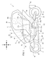
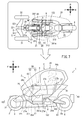
- FIG. 1 is a left side view showing an outline of the overall configuration of the lean vehicle according to the first embodiment.
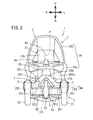
- FIG. 2 is a front view showing an outline of the overall configuration of the lean vehicle according to the first embodiment.
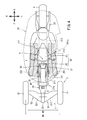
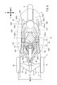
- FIG. 3 is an exploded perspective view showing a schematic structure of the vehicle body frame.
- FIG. 4 is a plan view schematically showing the positional relationship between the vehicle body frame, the vehicle body cover, and the driver.
- FIG. 5 is a schematic view of the tilted link mechanism when the vehicle body frame is tilted to the left when viewed from the rear.
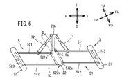
- FIG. 6 is a schematic view of the tilted link mechanism when the vehicle body frame is tilted to the right when viewed from the rear.
- FIG. 1 is a left side view showing an outline of the overall configuration of the lean vehicle according to the first embodiment.
- FIG. 2 is a front view showing an outline of the overall configuration of the lean vehicle according to the first embodiment.
- FIG. 3 is an exploded perspective view showing a schematic structure
- FIG. 7 is a side-by-side view of the left side view of the lean vehicle and the plan view schematically showing the positional relationship between the vehicle body frame, the vehicle body cover, and the driver.
- FIG. 8 is a left side view showing an outline of the overall configuration of the lean vehicle according to the second embodiment.
- FIG. 9 is a plan view showing a schematic configuration of a vehicle body frame of the lean vehicle according to the second embodiment.
- the arrow F in the figure indicates the forward direction of the lean vehicle 1,1001.
- the arrow B in the figure indicates the rear direction of the lean vehicle 1,1001.
- the arrow U in the figure indicates the upward direction of the lean vehicle 1,1001.
- the arrow D in the figure indicates the downward direction of the lean vehicle 1,1001.
- the arrow R in the figure indicates the right direction of the lean vehicle 1,1001.
- the arrow L in the figure indicates the left direction of the lean vehicle 1,1001.
- the front-rear direction, the left-right direction, and the up-down direction of the lean vehicle 1,1001 are the front-rear direction and the left-right direction based on the lean vehicle 1,1001 when viewed from the driver who drives the lean vehicle 1,1001, respectively. And up and down.
- the lean vehicles 1, 1001 of each embodiment turn by inclining the vehicle body frames 21, 1021 in the left-right direction with respect to the vertical direction. Therefore, in FIGS. 5 and 6 showing the state in which the vehicle body frame 21 is tilted, the direction with respect to the vehicle body frame 21 is defined as follows in addition to the direction with respect to the lean vehicle 1 described above.
- the arrow FU in the figure indicates the upward direction of the vehicle body frame 21.
- the arrow FD in the figure indicates the downward direction of the vehicle body frame 21.
- the arrow FR in the figure indicates the right direction of the vehicle body frame 21.
- the arrow FL in the figure indicates the left direction of the vehicle body frame 21.
- the horizontal direction and the vertical direction of the vehicle body frame 21 mean the horizontal direction and the vertical direction with respect to the vehicle body frame 21 when viewed from the occupant who drives the lean vehicle 1, respectively.
- FIG. 1 is a left side view showing an outline of the overall configuration of the lean vehicle 1 according to the first embodiment.
- FIG. 2 is a front view showing an outline of the overall configuration of the lean vehicle 1.
- the lean vehicle 1 includes a vehicle body 2, a pair of left and right front wheels 3, a rear wheel 4, an inclined link mechanism 5, a steering mechanism 6, a shock absorber 7, and a power unit 8 (drive source).
- the lean vehicle 1 of the present embodiment is a vehicle that inclines to the left when turning to the left and to the right when turning to the right. That is, the lean vehicle 1 of the present embodiment tilts the vehicle body 2 and the pair of left and right front wheels 3 to the left when turning to the left, and tilts the vehicle body 2 and the pair of left and right front wheels 3 to the right when turning to the right. It is a vehicle that tilts to the right.
- the vehicle body 2 has a vehicle body frame 21, a rear arm 23, a vehicle body cover 26, and a seat 27.
- the vehicle body frame 21 is in an upright state.
- the vehicle body frame 21 is premised on an upright state.
- the upright state of the vehicle body frame 21 means that the vertical direction of the vehicle body frame 21 is the same as the vertical direction.
- the vehicle body frame 21 supports mounting parts mounted on the lean vehicle 1, such as the vehicle body cover 26, the seat 27, and the power unit 8. Specifically, the vehicle body frame 21 supports the inclined link mechanism 5 at the front portion. The vehicle body frame 21 supports the rear arm support portion 24, the seat 27, and the power unit 8 at the rear portion.
- the power unit 8 has, for example, a motor that is a driving force generation source.
- the power unit 8 may have an engine as the driving force generation source, or may have a hybrid system in which an engine and a motor are combined.
- the driving force output from the power unit 8 is transmitted to the rear wheels 4 by the drive transmission unit 8a.
- the drive transmission unit 8a is supported by a rear arm 23, which will be described later, that rotatably supports the rear wheel 4.
- the drive transmission unit 8a includes, for example, a chain or the like.
- FIG. 3 is an exploded perspective view showing a schematic configuration of a vehicle body frame 21, a pair of left and right front wheels 3, a rear wheel 4, an inclined link mechanism 5, and a steering mechanism 6.
- the vehicle body frame 21 has a main skeleton portion 21a, an inclined link mechanism support portion 22, a rear arm support portion 24, and a handle support portion 25.
- the main skeleton portion 21a is a frame constituting the skeleton of the vehicle body 2 of the lean vehicle 1.
- the detailed configuration of the main skeleton portion 21a will be described later, but the main skeleton portion 21a includes a front skeleton portion 211 and a posterior skeleton portion 212.
- the anterior skeleton portion 211 is located in front of the posterior skeleton portion 212 in the main skeleton portion 21a.
- the posterior skeleton portion 212 is located behind the anterior skeleton portion 211 in the main skeleton portion 21a.
- the anterior skeleton portion 211 and the posterior skeleton portion 212 are connected in a state of being arranged in the front-rear direction.
- the front skeleton portion 211 supports the inclined link mechanism support portion 22 at the front portion.
- the rear skeleton portion 212 supports the power unit 8 and the seat 27 at the front portion, and supports the rear arm support portion 24 at the rear portion.
- the seat 27 is supported by the rear skeleton portion 212 of the vehicle body frame 21.
- the seat 27 has a seating portion 27a and a seat back 27b.
- the seating portion 27a of the seat 27 is supported by the upper portion of the posterior skeleton portion 212.
- the upper surface of the seating portion 27a is a seating surface 27c on which the driver is seated.
- the inclined link mechanism support portion 22 is connected to the front end of the anterior skeleton portion 211.
- the tilted link mechanism support portion 22 supports the tilted link mechanism 5, which will be described later.
- the inclined link mechanism 5 supports a pair of left and right front wheels 3. That is, the inclined link mechanism support portion 22 supports the pair of left and right front wheels 3 via the inclined link mechanism 5.
- the detailed configuration of the inclined link mechanism 5 will be described later.
- the inclined link mechanism support portion 22 is separable from the anterior skeleton portion 211. Therefore, the inclined link mechanism 5 supported by the inclined link mechanism supporting portion 22 is also separable from the main skeleton portion 21a. Further, the inclined link mechanism support portion 22 is also separable from the handle support portion 25, which will be described later, which is connected to the main skeleton portion 21a.
- the pair of left and right front wheels 3 includes a left front wheel 31 located to the left of the vehicle body frame 21 and a right front wheel 32 located to the right of the vehicle body frame 21.
- the left arm mechanism 51 of the inclined link mechanism 5, which will be described later, extends from the inclined link mechanism support portion 22 to the left so as to support the left front wheel 31 with respect to the vehicle body frame 21.
- the right arm mechanism 52 of the inclined link mechanism 5, which will be described later, extends from the inclined link mechanism support portion 22 to the right so as to support the right front wheel 32 with respect to the vehicle body frame 21.
- a shock absorber support portion 28 that supports the shock absorber 7 is arranged between the inclined link mechanism support portion 22 and the anterior skeleton portion 211.
- the shock absorber support portion 28 is connected to the upper portion of the inclined link mechanism support portion 22 and the front lower end portion of the handle support portion 25 connected to the front skeleton portion 211.
- the shock absorber support portion 28 has a shock absorber support main body portion 28a and a tower portion 28b.
- the shock absorber support main body 28a is a cylindrical member and supports the base end portion of the tower portion 28b extending in the vertical direction.
- the shock absorber support main body 28a is connected to the front lower end portion of the inclined link mechanism support portion 22 and the handle support portion 25.
- the buffer device 7 buffers the movements of the left front wheel 31 and the right front wheel 32.
- the shock absorber 7 includes a left shock absorber 71 and a right shock absorber 72.
- the left shock absorber 71 is provided so as to connect the tower portion 28b and the upper left arm member 511 of the inclined link mechanism 5, which will be described later.
- the right shock absorber 72 is provided so as to connect the tower portion 28b and the upper right arm member 521 of the inclined link mechanism 5, which will be described later.
- the left shock absorber 71 and the right shock absorber 72 have a spring and a damper, respectively.
- the left shock absorber 71 buffers the force input from the road surface to the left front wheel 31, and positions the left front wheel 31 with respect to the vehicle body frame 21.
- the right buffer device 72 buffers the force input from the road surface to the right front wheel 32, and positions the right front wheel 32 with respect to the vehicle body frame 21.
- the handle support portion 25 is connected to the upper portion of the front portion of the front skeleton portion 211, and extends upward from the upper portion of the front skeleton portion 211.
- the height H5 of the upper end of the handle support portion 25 is higher than the seating surface 27c of the seat 27.
- the upper end of the handle support portion 25 is a portion located at the top of the handle support portion 25 in the vertical direction.
- a part of the handle support portion 25 may extend upward from the upper part of the main skeleton portion 21a other than the front skeleton portion 211. That is, as long as at least a part of the handle support portion 25 extends upward from the upper part of the front skeleton portion 211, the handle support portion 25 may be provided in the main skeleton portion 21a in any way.
- the handle support portion 25 is formed of a member separate from the main skeleton portion 21a.
- the handle support portion 25 may extend upward from the upper portion of a portion other than the front skeleton portion 211. That is, the handle support portion 25 may extend upward from the upper portion of the main skeleton portion 21a.
- the handle support portion 25 supports the bar handle 61 and the steering shaft 62 of the steering mechanism 6.
- the handle support portion 25 has a height such that the bar handle 61 of the steering mechanism 6 is positioned so that the driver who is seated on the seating surface 27c of the seat 27 can easily grip the bar handle 61.
- the steering mechanism 6 includes a bar handle 61, a steering shaft 62, a steering shaft support portion 63, and a steering force transmission portion (not shown).
- the bar handle 61 is a bar member extending in the left-right direction and is connected to the upper end portion of the steering shaft 62.
- the steering shaft 62 is rotatably supported by the steering shaft support portion 63 fixed to the upper portion of the steering wheel support portion 25 as described later.
- the steering shaft 62 is connected to the steering force transmitting portion so as to transmit the rotation of the bar handle 61.
- the steering force transmission unit transmits the rotation of the steering shaft 62 to the left front wheel 31 and the right front wheel 32 as steering force in the left-right direction. The detailed configuration of the steering force transmission unit will not be described.
- the steering handle SH is configured by the bar handle 61 and the steering shaft 62.
- the steering shaft 62 is a portion supported by the steering shaft support portion 63, and does not include other rotating shafts connected to the steering shaft 62 by a transmission component.
- the steering handle SH rotates about the steering shaft P.
- the handle support portion 25 of the present embodiment has four handle support leg portions 25a, a plurality of handle support beam portions 25b, and a handle support top plate portion 25c.
- the four handle support legs 25a and the plurality of handle support beams 25b are plate-shaped bar members that are long in one direction, respectively.
- the handle support top plate portion 25c is a flat plate member.
- the upper ends of the four handle support legs 25a are connected to the handle support top plate 25c.
- the four handle support legs 25a are connected in the left-right direction by a part of the plurality of handle support beam portions 25b, and are connected in the front-rear direction by the other part of the plurality of handle support beam portions 25b.
- the four handle support legs 25a, the plurality of handle support beams 25b, and the handle support top plate 25c are integrally formed.
- the handle support portion 25 is formed in a turret shape by a plate-shaped bar member.
- the lower ends of the four handle support legs 25a are fixed to the front skeleton portion 211.
- the method of fixing the four handle support legs 25a to the front skeleton portion 211 is a method in which the handle support legs 25a can be fixed to the front skeleton portion 211 such as welding, fastening using a fastening member, and adhesion. If so, any method may be used.
- a steering shaft support portion 63, which will be described later, of the steering mechanism 6 is fixed on the handle support top plate portion 25c.
- the bar handle 61 is connected to a steering shaft 62 rotatably supported by a steering shaft support 63.
- the handle support portion 25 supports the steering handle SH composed of the bar handle 61 and the steering shaft 62.
- the rear arm support portion 24 is connected to the rear end of the rear skeleton portion 212.
- the rear arm support portion 24 rotatably supports the front portions of the pair of left and right rear arms 23.
- the pair of left and right rear arms 23 extend rearward from the rear arm support portion 24, respectively.
- a pair of left and right rear arms 23 rotatably support the rear wheels 4 at their rear portions.
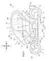
- the body cover 26 (cover) is supported by the body frame 21.
- the vehicle body cover 26 includes a vehicle body cover main body 26a that covers the vehicle body frame 21 and an upper cover 26b that is located above the vehicle body cover main body 26a.
- the upper cover 26b is formed in a convex shape so as to project upward when viewed from the left-right direction. As a result, the upper cover 26b forms a riding space for the driver to ride between the upper cover 26b and the vehicle body cover main body 26a. Therefore, since the driver driving the lean vehicle 1 is not directly exposed to the wind and rain, the comfort of the driver can be improved.
- the upper cover 26b is formed so as to be located above the driver's head while the driver is seated on the seating surface 27c of the seat 27.
- the vehicle body cover main body 26a is formed so as to cover the right portion of the driver seated on the seating surface 27c of the seat 27 while opening the left portion of the driver. As a result, the driver can get on and off the lean vehicle 1 from the left.
- An opening 26c is formed in the lower right part of the vehicle body cover body 26a.
- the opening 26c is provided so that the right foot of the driver seated on the seating surface 27c of the seat 27 can penetrate and land on the ground. That is, the lean vehicle 1 is located to the right of the driver so as to cover the right portion of the driver seated on the seat 27, and when the right foot of the driver seated on the seat 27 lands.
- a vehicle body cover 26 having an opening 26c through which the right foot can penetrate is provided. Thereby, the convenience of the lean vehicle 1 can be improved.
- the above-described configuration eliminates the need for the lean vehicle 1 to have an independent function, so that the configuration of the lean vehicle 1 can be simplified.
- plate-shaped left step 261 and right step 262 are provided in a portion facing the riding space in the front lower portion of the vehicle body cover main body 26a.
- the left step 261 is located on the left side of the vehicle body cover main body 26a, and the left foot of the driver seated on the seating surface 27c of the seat 27 is placed on the left step 261.
- the front part of the left step 261 is inclined forward and upward.
- the right step 262 is located on the right side of the vehicle body cover main body 26a, and the right foot of the driver seated on the seating surface 27c of the seat 27 is placed on the right step 262.
- the front portion of the right step 262 is inclined forward and upward.
- FIG. 4 is a plan view schematically showing the relationship between the driver, the vehicle body frame 21, and the vehicle body cover 26.
- FIG. 7 is a diagram showing FIG. 4 side by side with FIG. In FIGS. 4 and 7, for the sake of explanation, the parts other than the vehicle body frame 21, the left front wheel 31, the right front wheel 32, the rear wheel 4, and the inclined link mechanism 5 are omitted from the lean vehicle 1, and the vehicle body is shown.
- the outer shape of the cover 26 is shown by a alternate long and short dash line.
- Left step 261 is located to the left of the main skeleton portion 21a in a plan view of the lean vehicle 1.
- the right step 262 is located to the right of the main skeleton portion 21a in a plan view of the lean vehicle 1. That is, the main skeleton portion 21a is located between the left step 261 and the right step 262 in the left-right direction.
- the left step 261 and the right step 262 are illustrated by a two-dot chain line and an oblique line for explanation.
- the left step 261 and the right step 262 are integrally formed with the vehicle body cover main body 26a.
- the left step and the right step may be provided separately from the vehicle body cover main body 26a.
- the left step 261 and the right step 262 are supported by the main skeleton portion 21a via the vehicle body cover main body 26a.
- the main skeleton portion 21a may be provided with a step support portion that supports the left step and the right step, respectively.
- the left step and the right step are each supported by the step support portion on the main skeleton portion 21a.
- the left-right distance WS between the left end of the left step 261 and the right end of the right step 262 is smaller than the tread width WH of the left front wheel 31 and the right front wheel 32. That is, the tread width WH of the left front wheel 31 and the right front wheel 32 is larger than the distance WS in the left-right direction between the left end of the left step 261 and the right end of the right step 262.
- the distance in the left-right direction from the ground contact position of the foot before the driver gets on the lean vehicle 1 to the seating surface 27c of the seat 27 is small. As a result, the driver can easily get on and off the lean vehicle 1.
- the tread width between the left front wheel 31 and the right front wheel 32 means the distance between the center of the left front wheel 31 and the center of the right front wheel 32 in the left-right direction of the lean vehicle 1.
- a recessed portion 261a is provided at the left rear portion of the left step 261.
- the recessed portion 261a allows the driver to easily get on and off the lean vehicle 1. Moreover, the driver can land his left foot on the ground while seated on the seating surface 27c of the seat 27. Thereby, the convenience of the lean vehicle 1 can be improved.
- the front portion of the vehicle body cover main body 26a is provided with a front cover 265 that covers the front of a link mechanism drive motor (not shown) that drives the inclined link mechanism 5 described later.
- the front cover 265 constitutes the front portion of the cabin C, which will be described later, so as to cover the front portion of the link mechanism drive motor and the front portion of the driver seated on the seating surface 27c of the seat 27.
- the front cover 265 has a light transmitting portion 265a so that the driver seated on the seating surface 27c of the seat 27 can visually recognize the pair of left and right front wheels 3.
- the light transmitting portion 265a is made of, for example, a transparent material.
- the light transmitting portion 265a may be made of any material as long as it is made of a material capable of transmitting light.
- the front cover 265 is located behind the pair of left and right front wheels 3.
- the left step 261 and the right step 262 are provided at the rear of the front cover 265. Therefore, the front cover 265 can prevent the water splashed by the pair of left and right front wheels 3 from entering the riding space, which is the space in which the driver is riding.
- the upper cover 26b and the front cover 265 of the vehicle body cover body 26a form a cabin C that covers the front and upper parts of the driver seated on the seating surface 27c of the seat 27.
- the cabin C may include a portion of the vehicle body cover body 26a that covers the left portion of the driver, or may include a portion of the vehicle body cover body 26a that covers the right portion of the driver, or the vehicle body cover.
- the portion of the main body 26a that covers the rear part of the driver may be included.
- FIG. 5 is a schematic view of the tilted link mechanism 5 when the vehicle body frame 21 is tilted to the left when viewed from the rear.
- FIG. 6 is a schematic view of the tilted link mechanism 5 when the vehicle body frame 21 is tilted to the right when viewed from the rear.
- the inclined link mechanism 5 is a double wishbone type link mechanism.
- the tilted link mechanism 5 is supported by the tilted link mechanism support portion 22.
- the tilted link mechanism 5 has a left arm mechanism 51 and a right arm mechanism 52.
- the left arm mechanism 51 is connected to the left portion of the inclined link mechanism support portion 22 and the left front wheel 31. As will be described later, the left arm mechanism 51 can rotate in the vertical direction with respect to the inclined link mechanism support portion 22 and the left front wheel 31, respectively. That is, the left arm mechanism 51 rotatably supports the left front wheel 31 with respect to the inclined link mechanism support portion 22 in the vertical direction.
- the left arm mechanism 51 swings upward with respect to the inclined link mechanism support portion 22 when the vehicle body frame 21 is inclined to the left, and lower with respect to the inclined link mechanism support portion 22 when the vehicle body frame 21 is inclined to the right. Swing to.
- the left arm mechanism 51 includes an upper left arm member 511, a lower left arm member 512, and a left knuckle 513.
- the upper left arm member 511 and the lower left arm member 512 are left swing arms.
- the upper left arm member 511 is a flat plate member, and is arranged between the inclined link mechanism support portion 22 and the left front wheel 31 so as to extend in the left-right direction.
- the right end portion of the upper left arm member 511 is rotatably connected to the inclined link mechanism support portion 22 in the vertical direction around the right end portion of the upper left arm member 511.
- the portion where the right end portion of the upper left arm member 511 is rotatably connected to the inclined link mechanism support portion 22 is the support portion 511a of the upper left arm member 511 with respect to the inclined link mechanism support portion 22.
- the left end portion of the upper left arm member 511 is rotatably connected to the left knuckle 513 connected to the wheel of the left front wheel 31 in the vertical direction around the left end portion of the upper left arm member 511.
- the lower left arm member 512 is a flat plate member, and is arranged under the upper left arm member 511 in parallel with the upper left arm member 511. That is, the lower left arm member 512 is also arranged between the inclined link mechanism support portion 22 and the left front wheel 31 so as to extend in the left-right direction, similarly to the upper left arm member 511.
- the right end portion of the lower left arm member 512 is rotatably connected to the inclined link mechanism support portion 22 in the vertical direction around the right end portion of the lower left arm member 512.
- the portion where the right end portion of the lower left arm member 512 is rotatably connected to the inclined link mechanism support portion 22 is the support portion 512a of the lower left arm member 512 with respect to the inclined link mechanism support portion 22.
- the left end portion of the lower left arm member 512 is rotatably connected to the left knuckle 513 connected to the wheel of the left front wheel 31 in the vertical direction around the left end portion of the lower left arm member 512.
- the left arm mechanism 51 With the configuration of the left arm mechanism 51 as described above, when the vehicle body frame 21 is tilted to the left, the left knuckle 513 is tilted to the left in parallel with the tilting link mechanism support portion 22. At this time, the upper left arm member 511 and the lower left arm member 512 are maintained in a parallel state. On the other hand, when the vehicle body frame 21 is tilted to the right, the left knuckle 513 is tilted to the right in parallel with the tilting link mechanism support portion 22. At this time, the upper left arm member 511 and the lower left arm member 512 are maintained in a parallel state.
- the right arm mechanism 52 is connected to the right portion of the inclined link mechanism support portion 22 and the right front wheel 32. As will be described later, the right arm mechanism 52 can rotate in the vertical direction with respect to the inclined link mechanism support portion 22 and the right front wheel 32, respectively. That is, the right arm mechanism 52 rotatably supports the right front wheel 32 in the vertical direction with respect to the inclined link mechanism support portion 22.
- the right arm mechanism 52 swings downward with respect to the inclined link mechanism support portion 22 when the vehicle body frame 21 is inclined to the left, and is upward with respect to the inclined link mechanism support portion 22 when the vehicle body frame 21 is inclined to the right. Swing to.
- the right arm mechanism 52 has an upper right arm member 521, a lower right arm member 522, and a right knuckle 523.
- the upper right arm member 521 and the lower right arm member 522 are right swing arms.
- the upper right arm member 521 is a flat plate member, and is arranged between the inclined link mechanism support portion 22 and the right front wheel 32 so as to extend in the left-right direction.
- the left end portion of the upper right arm member 521 is rotatably connected to the inclined link mechanism support portion 22 in the vertical direction around the left end portion of the upper right arm member 521.
- the portion where the left end portion of the upper right arm member 521 is rotatably connected to the inclined link mechanism support portion 22 is the support portion 521a of the upper right arm member 521 with respect to the inclined link mechanism support portion 22.
- the right end portion of the upper right arm member 521 is rotatably connected to the right knuckle 523 connected to the wheel of the right front wheel 32 in the vertical direction around the right end portion of the upper right arm member 521.
- the lower right arm member 522 is a flat plate member, and is arranged under the upper right arm member 521 in parallel with the upper right arm member 521. That is, the lower right arm member 522 is also arranged between the inclined link mechanism support portion 22 and the right front wheel 32 so as to extend in the left-right direction, similarly to the upper right arm member 521.
- the left end portion of the lower right arm member 522 is rotatably connected to the inclined link mechanism support portion 22 in the vertical direction around the left end portion of the lower right arm member 522.
- the portion where the left end portion of the lower right arm member 522 is rotatably connected to the inclined link mechanism support portion 22 is the support portion 522a of the lower right arm member 522 with respect to the inclined link mechanism support portion 22.
- the right end portion of the lower right arm member 522 is rotatably connected to the right knuckle 523 connected to the wheel of the right front wheel 32 in the vertical direction around the right end portion of the lower right arm member 522.
- the right arm mechanism 52 With the configuration of the right arm mechanism 52 as described above, when the vehicle body frame 21 is tilted to the left, the right knuckle 523 is tilted to the left in parallel with the tilting link mechanism support portion 22. At this time, the upper right arm member 521 and the lower right arm member 522 maintain a parallel state. On the other hand, when the vehicle body frame 21 is tilted to the right, the right knuckle 523 is tilted to the right in parallel with the tilting link mechanism support portion 22. At this time, the upper right arm member 521 and the lower right arm member 522 maintain a parallel state.
- the vehicle body frame 21, the left front wheel 31, and the right front wheel 32 can be inclined to the left or right by the inclined link mechanism 5 having the above-described configuration.
- the above-mentioned tilt link mechanism 5 may be configured so that the tilt in the left-right direction is controlled by the link mechanism drive motor.
- the link mechanism drive motor is arranged, for example, behind the inclined link mechanism support portion 22 and behind the front cover 265.
- the main skeleton portion 21a extends in the front-rear direction. That is, the width of the main skeleton portion 21a in the left-right direction is smaller than the length of the main skeleton portion 21a in the front-rear direction.
- the main skeleton portion 21a includes an anterior skeleton portion 211 and a posterior skeleton portion 212.
- the anterior skeleton portion 211 is located in front of the posterior skeleton portion 212.
- the anterior skeleton portion 211 extends in the anteroposterior direction.
- the anterior skeleton portion 211 has a pair of anterior skeleton side wall portions 211a and an anterior skeleton bottom wall portion 211b.
- the pair of anterior skeleton side wall portions 211a are located side by side in the left-right direction and are long in the front-rear direction.
- the front skeleton bottom wall portion 211b connects the lower ends of the pair of front skeleton side wall portions 211a.
- the pair of anterior skeleton side wall portions 211a and the anterior skeleton bottom wall portion 211b are connected by welding, for example.
- the pair of front skeleton side wall portions 211a and front skeleton bottom wall portion 211b may be connected by adhesion, bolts, or the like, or may be integrally formed.
- the height dimension of the pair of front skeleton side wall portions 211a is lower in the rear portion than in the front portion, respectively.
- the front skeleton portion 211 can be arranged at the feet of the driver seated on the seating surface 27c of the seat 27. Therefore, since the main skeleton portion 21a can be arranged in the lower part of the lean vehicle 1, the center of gravity of the lean vehicle 1 can be lowered.
- the portion of the main skeleton portion 21a located before the center X in the front-rear direction of the left step 261 and the right step 262 is the main skeleton front portion 121.
- the main skeleton anterior portion 121 includes a part of the anterior skeleton portion 211.
- the front portion 121 of the main skeleton extends linearly in the front-rear direction.
- the distance D between the support portion 511a of the upper left arm 511 with respect to the tilted link mechanism support portion 22 and the support portion 521a of the upper right arm 521 with respect to the tilted link mechanism support portion 22 in the dimension WF in the vehicle width direction of the main skeleton front portion 121 (FIG. It is configured to be larger than 5 and FIG. 6).
- the distance D (the distance D between the support portion 512a of the lower left arm 512 with respect to the tilted link mechanism support portion 22 and the support portion 522a of the lower right arm 522 with respect to the tilted link mechanism support portion 22 of the main skeleton front portion 121 in the vehicle width direction is It is configured to be larger than (see FIGS. 5 and 6).
- the upper end of the main skeleton front portion 121 is lower than the lower end of the steering handle SH. That is, the height H2 at the upper end of the front portion 121 of the main skeleton is smaller than the height H1 at the lower end of the steering handle SH.
- the lower end of the steering handle SH is the lowermost portion of the bar handle 61 and the steering shaft 62. In the case of this embodiment, the lower end of the steering handle SH is the lower end of the steering shaft 62.
- the upper end of the main skeleton front portion 121 is the uppermost portion of the main skeleton front portion 121.
- the upper end of the main skeleton front portion 121 is the front portion of the front skeleton portion 211.
- the upper end of the front part 121 of the main skeleton is lower than the seating surface 27c of the seat 27. That is, the height H2 of the upper end of the main skeleton front portion 121 is smaller than the height H3 of the seating surface 27c of the seat 27.
- the height H3 of the seating surface 27c of the above-mentioned seat is the height of the lowest portion of the seating surface 27c.
- the upper end of the main skeleton front portion 121 is lower than the upper end of the inclined link mechanism 5. That is, as shown in FIG. 2, the height H2 of the upper end of the main skeleton front portion 121 is smaller than the height H4 of the inclined link mechanism 5. As a result, it is possible to increase the degree of freedom in the riding position of the driver and the layout of the mounted parts mounted on the vehicle body frame. Therefore, the degree of freedom in designing the lean vehicle can be increased.
- the upper end of the inclined link mechanism 5 is the uppermost portion of the inclined link mechanism 5.
- the height in this embodiment means the height from the road surface on which the lean vehicle 1 travels.
- a plate-shaped reinforcing member 213 is provided on the upper portion of the central portion in the front-rear direction of the pair of front skeleton side wall portions 211a.
- the reinforcing member 213 is connected to the central portion in the front-rear direction of the pair of front skeleton side wall portions 211a so as to straddle the left-right direction. It is not necessary to provide the reinforcing member 213.
- the reinforcing member 213 may have another shape such as a rod shape.
- the posterior skeleton portion 212 is located behind the anterior skeleton portion 211.
- the posterior skeleton portion 212 extends in the anteroposterior direction.
- the posterior skeleton portion 212 has a pair of posterior skeleton side wall portions 212a and a plurality of posterior skeleton beam portions 212b.
- the pair of posterior skeleton side wall portions 212a are located side by side in the left-right direction and are long in the front-rear direction.
- the plurality of posterior skeleton beam portions 212b connect a pair of posterior skeleton side wall portions 212a in the left-right direction.
- the vertical dimension of the rear skeleton portion 212 is larger than the vertical dimension of the front skeleton portion 211.
- the left-right dimension of the posterior skeleton portion 212 is smaller than the left-right dimension of the front skeleton portion 211.
- the rear skeleton portion 212 supports the power unit 8.
- the posterior skeleton portion 212 supports the seat 27 at the top.
- the rear skeleton portion 212 supports the rear arm support portion 24 at the rear end portion.
- An opening 212c is formed in the rear skeleton side wall portion 212a of the posterior skeleton portion 212.
- the posterior skeleton side wall portion 212a may not be provided with an opening.
- the anterior skeleton portion 211 and the posterior skeleton portion 212 are connected side by side in the front-rear direction.
- the vehicle body frame 21 has a long shape in the front-rear direction as described above.
- the portion located behind the center X in the front-rear direction of the left step 261 and the right step 262 is the rear portion 122 of the main skeleton.
- the rear main skeleton 122 includes a posterior anterior skeleton 211 and a posterior skeleton 212.
- the main skeleton portion 21a is located between the left step 261 and the right step 262 provided on the vehicle body cover main body 26a in a plan view.
- the main skeleton portion 21a extends linearly in the front-rear direction between the driver's legs when the driver puts his / her feet on the left step 261 and the right step 262 while the driver is seated on the seat 27.
- the main skeleton portion 21a supports the inclined link mechanism 5 by the main skeleton front portion 121 located in front of the front-rear direction center X of the left step 261 and the right step 262, and the left-right step 261 and the right step 262 are centered in the left-right direction.
- the seat 27, the rear wheels 4, and the power unit 8 are supported by the rear portion 122 of the main skeleton located behind the X.
- the main skeleton front portion 121 views at least a part of the inclined link mechanism 5 at a position below the upper surface of at least a part of the left step 261 and the right step 262 in the side view of the lean vehicle 1.
- the main skeleton portion 21a has a shape that is narrow and extends linearly.
- the main skeleton portion 21a supports an inclined link mechanism 5 that supports the vehicle body frame 21, the left front wheel 31 and the right front wheel 32 so as to be inclined in the left-right direction by the main skeleton front portion 121, and the other by the main skeleton rear portion 122. Support the mounted parts.
- the main skeleton portion 21a of the present embodiment has left step 261 and right step 262 in which the driver puts his / her foot on the seating surface 27c of the seat 27 in the side view of the lean vehicle 1. It extends linearly in the anteroposterior direction, at least below some of the upper surfaces. As a result, it is possible to increase the degree of freedom in the riding position of the driver and the layout of the mounted parts mounted on the vehicle body frame 21. Therefore, the degree of freedom in designing the lean vehicle 1 can be increased.
- the driver can use the lean vehicle 1 even in the case of the lean vehicle 1 of the present embodiment having the upper cover 26b. Easy to get on and off.
- the main skeleton front portion 121 is provided with a support portion 511a of the upper left arm member 511 with respect to the vehicle body frame 21 and a support portion 521a of the upper right arm member 521 with respect to the vehicle body frame 21 having a dimension WF in the vehicle width direction.
- the space By configuring the space to be larger than the interval D, the rigidity of the main skeleton front portion 121 can be increased as compared with the portion of the vehicle body frame 21 that supports the upper left arm member 511 and the upper right arm member 521.
- the dimension WF of the main skeleton front portion 121 in the vehicle width direction is larger than the distance D between the support portion 512a of the lower left arm member 512 with respect to the vehicle body frame 21 and the support portion 522a of the lower right arm member 522 with respect to the vehicle body frame 21.
- the rigidity of the front part 121 of the main skeleton can be increased as compared with the portion of the vehicle body frame 21 that supports the lower left arm member 512 and the lower right arm member 522. Therefore, it is possible to suppress the deformation of the main skeleton front portion 121 by the force input from the left front wheel 31 via the lower left arm member 512 and the force input from the right front wheel 32 via the lower right arm member 522. .. Therefore, with the above configuration, the rigidity of the entire body frame 21 can be increased.
- FIG. 8 is a left side view showing a schematic configuration of the lean vehicle 1001 according to the second embodiment.
- FIG. 9 is a plan view showing a schematic configuration of the vehicle body frame 1021 of the lean vehicle 1001.
- the floor 1029 described later including the left step 261 and the right step 262 is shown by a two-dot chain line and an oblique line.
- the configuration of the vehicle body frame 1021 is different from the configuration of the vehicle body frame 21 of the lean vehicle 1 of the first embodiment.
- the same components as those in the first embodiment are designated by the same reference numerals and the description thereof will be omitted, and only the parts different from the first embodiment will be described.
- the vehicle body frame 1021 has a main skeleton portion 1021a, an inclined link mechanism support portion 22, and a handle support portion 25.
- the main skeleton portion 1021a has a pipe-shaped left main frame 1041 and a right main frame 1042 extending in the front-rear direction under the left step 261 and the right step 262.
- the left main frame 1041 is located on the left side of the lean vehicle 1001 in a plan view.
- the right main frame 1042 is located on the right side of the lean vehicle 1001 in a plan view.
- the left main frame 1041 and the right main frame 1042 of the present embodiment are provided symmetrically with respect to the center in the left-right direction of the lean vehicle 1001 in a plan view.
- the left step 261 and the right step 262 are composed of a plate-shaped floor 1029 located on the left main frame 1041 and the right main frame 1042.
- the front part of floor 1029 is inclined forward and upward.
- the rear part of the floor 1029 is flat. That is, in the present embodiment, the left step 261 and the right step 262 are integrally formed.
- the upper surfaces of the left step 261 and the right step 262 are the upper surfaces of the floor 1029.
- the left main frame 1041 has a left main frame front portion 1041a, a left main frame rear portion 1041c, and a left main frame intermediate portion 1041b.
- the left main frame front portion 1041a, the left main frame intermediate portion 1041b, and the left main frame rear portion 1041c are connected side by side in the front-rear direction.
- the left main frame intermediate portion 1041b extends in the front-rear direction under the left step 261.
- the left main frame intermediate portion 1041b supports the seat 27.
- the left main frame front portion 1041a extends diagonally forward and upward from the front portion of the left main frame intermediate portion 1041b.
- the left main frame front portion 1041a is formed so that the front end portion approaches the front end portion of the right main frame front portion 1042a, which will be described later, that is, the front end portion approaches the center of the lean vehicle 1 in the left-right direction in a plan view. There is.
- the front end portion of the left main frame front portion 1041a is connected to the inclined link mechanism support portion 22 via the shock absorber support portion 28.
- the left main frame front portion 1041a supports the handle support portion 25 together with the right main frame front portion 1042a described later.
- the left main frame rear portion 1041c has a shape that extends upward from the rear end of the left main frame intermediate portion 1041b and is bent so as to go backward.
- the left main frame rear portion 1041c is integrally formed with the left main frame intermediate portion 1041b.
- the right main frame 1042 has a right main frame front portion 1042a, a right main frame rear portion 1042c, and a right main frame intermediate portion 1042b.
- the front right main frame 1042a, the middle right main frame 1042b, and the rear right main frame 1042c are connected side by side in the front-rear direction.
- the right main frame intermediate portion 1042b extends in the front-rear direction under the right step 262.
- the right main frame intermediate portion 1042b supports the seat 27.
- the right main frame front portion 1042a extends diagonally forward and upward from the front portion of the right main frame intermediate portion 1042b.
- the right main frame front portion 1042a is formed so that the front end portion approaches the front end portion of the right main frame front portion 1042a described later, that is, the front end portion approaches the center in the left-right direction of the lean vehicle 1 in a plan view. There is.
- the front end portion of the right main frame front portion 1042a is connected to the inclined link mechanism support portion 22 via the shock absorber support portion 28.
- the right main frame front portion 1042a supports the handle support portion 25 together with the left main frame front portion 1041a.
- the right main frame rear portion 1042c has a shape that extends upward from the right main frame intermediate portion 1042b and is bent so as to go backward.
- the right main frame rear portion 1042c is integrally formed with the right main frame intermediate portion 1042b.
- the left main frame intermediate portion 1041b and the right main frame intermediate portion 1042b are connected by a front connecting portion 1043 extending in the left-right direction.
- the left main frame rear portion 1041c and the right main frame rear portion 1042c are connected by a rear connecting portion 1044 extending in the left-right direction behind the front connecting portion 1043.
- the rear connecting portion 1044 rotatably supports the front portion of the swing arm 1023 in the vertical direction.
- the swing arm 1023 rotatably supports the rear wheel 4 instead of the rear arm of the first embodiment.
- the swing arm 1023 is provided with a power unit 8.
- a battery 81 that supplies electric power to the power unit 8 is arranged between the left mainframe intermediate portion 1041b and the right mainframe intermediate portion 1042b.
- the drive source of the lean vehicle 1001 includes an engine
- a fuel tank is arranged between the left main frame intermediate portion 1041b and the right main frame intermediate portion 1042b.
- the main skeleton portion 1021a extends linearly in the front-rear direction at a position below the upper surfaces of the left step 261 and the right step 262. As a result, the center of gravity of the lean vehicle 1001 can be lowered, and the driver can easily get on and off the lean vehicle 1001.
- the main skeleton portion 1021a is positioned below the upper surface of the left step 261 and the right step 262 on which the driver rests his / her foot while sitting on the seating surface 27c of the seat 27 in the side view of the lean vehicle 1001. Therefore, by configuring the vehicle so as to extend linearly in the front-rear direction, it is possible to increase the degree of freedom in the riding position of the driver and the layout of the mounted parts mounted on the vehicle body frame 1021. Therefore, the degree of freedom in designing the lean vehicle 1001 can be increased.
- the portion located in front of the center X in the front-rear direction of the left step 261 and the right step 262 is the main skeleton front portion 1121.
- the main skeleton front portion 1121 includes a left main frame front portion 1041a, a right main frame front portion 1042a, a front portion of the left main frame intermediate portion 1041b, and a front portion of the right main frame intermediate portion 1042b.
- the portion located behind the center X in the front-rear direction of the left step 261 and the right step 262 is the main skeleton rear portion 1122.
- the main skeleton rear 1122 includes the rear of the left main frame middle 1041b, the rear of the right main frame middle 1042b, the left main frame rear 1041c and the right main frame rear 1042c.
- the main skeleton portion 1021a supports the inclined link mechanism 5 by the main skeleton front portion 1121 and the seat 27, the rear wheel 4 and the power unit 8 by the main skeleton rear portion 1122.
- the main skeleton portion 1021a of the vehicle body frame 1021 supports the inclined link mechanism 5 that supports the vehicle body frame 1021, the left front wheel 31 and the right front wheel 32 so as to be inclined in the left-right direction by the main skeleton front portion 1121.
- the rear part 1122 of the main skeleton supports other mounting components.
- the upper end of the main skeleton front portion 1121 is lower than the lower end of the steering handle SH. That is, the height H2 of the upper end of the front part 1121 of the main skeleton is smaller than the height H1 of the lower end of the steering handle SH.
- the degree of freedom in designing the lean vehicle 1001 can be increased.
- the lower end of the steering handle SH is the lowermost portion of the bar handle 61 and the steering shaft 62. In the case of this embodiment, the lower end of the steering handle SH is the lower end of the steering shaft 62.
- the upper end of the main skeleton front part 1121 is the uppermost part in the main skeleton front part 1121.
- the upper end of the main skeleton front portion 1121 is the front end of the left main frame front portion 1041a and the right main frame 1042a.
- the upper end of the front part 1121 of the main skeleton is lower than the seating surface 27c of the seat 27. That is, the height H2 of the upper end of the front part 1121 of the main skeleton is smaller than the height H3 of the seating surface 27c of the seat 27.
- the height H3 of the seating surface 27c of the above-mentioned seat is the height of the lowest portion of the seating surface 27c.
- the height in the present embodiment means the height from the road surface on which the lean vehicle 1001 travels.
- the left-right distance WS between the left end of the left step 261 and the right end of the right step 262 is smaller than the tread width WH of the left front wheel 31 and the right front wheel 32. That is, the tread width WH of the left front wheel 31 and the right front wheel 32 is larger than the distance WS in the left-right direction between the left end of the left step 261 and the right end of the right step 262.
- the distance in the left-right direction from the ground contact position of the foot before the driver gets on the lean vehicle 1001 to the seating surface 27c of the seat 27 is small. As a result, the driver can easily get on and off the lean vehicle 1001.
- the tread width between the left front wheel 31 and the right front wheel 32 means the distance between the center of the left front wheel 31 and the center of the right front wheel 32 in the left-right direction of the lean vehicle 1001.
- the main skeleton front portion 1121 is an inclined link at a position below the upper surface of at least a part of the left step 261 and the right step 262 in the side view of the lean vehicle 1001. Supports at least part of the mechanism 5.
- the main skeleton front portion 1121 has a dimension WF in the vehicle width direction of the support portion 511a of the upper left arm member 511 with respect to the vehicle body frame 1021 and the upper right arm member with respect to the vehicle body frame 1021.
- the distance D from the support portion 521a of the 521 is larger than the distance D.
- the dimension WF in the vehicle width direction of the main skeleton front portion 1121 is larger than the distance D between the support portion 512a of the lower left arm member 512 with respect to the vehicle body frame 1021 and the support portion 522a of the lower right arm member 522 with respect to the vehicle body frame 1021. It is configured to be.
- the dimension WF in the vehicle width direction of the main skeleton front portion 1121 is the vehicle width direction dimension of the front end portion of the main skeleton front portion 1121.
- the handle support portion 25 is provided separately from the front skeleton portion 211.
- the handle support portion may be provided integrally with the anterior skeleton portion. That is, the handle support portion may be provided integrally with the main skeleton portion.
- the main skeleton portion 21a includes a front skeleton portion 211 and a posterior skeleton portion 212.
- the main skeleton portion may include at least a part of the casing of the power unit in addition to the anterior skeleton portion and the posterior skeleton portion.
- the inclined link mechanism 5 is a double wishbone type link mechanism having an upper left arm 511 and an upper right arm 521, and a lower left arm 512 and a lower right arm 522.
- the tilted link mechanism may have only one arm, the upper arm and the lower arm.
- the main skeleton portion 21a includes a front skeleton portion 211 and a posterior skeleton portion 212.
- the main skeleton portion may be integrally formed, or may be formed by connecting three or more members in the front-rear direction.
- the main skeleton portion may be configured by connecting a plurality of parts in the left-right direction.
- the main skeleton portion may be configured by using a pipe member.
- the rear portion of the anterior skeleton portion 211 is lower than the anterior portion.
- the anterior skeleton may have the same height in the anterior-posterior direction, or the anterior portion may be lower than the posterior portion.
- the left-right dimension of the posterior skeleton portion 212 is smaller than the left-right dimension of the anterior skeleton portion 211, and the height of the posterior skeleton portion 212 is larger than the height of the anterior skeleton portion 211.
- the left-right dimension of the posterior skeleton portion may be the same as or larger than the left-right dimension of the anterior skeleton portion.
- the height of the posterior skeleton may be the same as the anterior skeleton or smaller than the anterior skeleton.
- the support portion 511a of the upper left arm 511 and the support portion 521a of the upper right arm 521 are located at separate positions.
- the support portion 512a of the lower left arm 512 and the support portion 522a of the lower right arm 522 are located at separate positions.
- the support portion of the upper left arm and the support portion of the upper right arm may be at the same position.
- the support portion of the lower left arm and the support portion of the lower right arm may be at the same position.
- the upper ends of the main skeleton front portions 121 and 1121 are lower than the lower ends of the steering handle SH.
- the upper end of the front portion of the main skeleton may be at the same height as or higher than the lower end of the steering handle.
- the upper ends of the main skeleton front portions 121 and 1121 are lower than the seating surface 27c of the seat 27.
- the upper end of the front portion of the main skeleton may be at the same height as the seating surface of the seat or higher than the seating surface.
- the upper end of the main skeleton front portion 121 is lower than the upper end of the inclined link mechanism 5.
- the upper end of the anterior portion of the main skeleton may be at or above the upper end of the tilted linkage.
- the tread width WH of the left front wheel 31 and the right front wheel 32 is larger than the distance WS in the left-right direction between the left end of the left step 261 and the right end of the right step 262.
- the tread width between the left front wheel and the right front wheel may be the same as or smaller than the horizontal distance between the left end of the left step and the right end of the right step.
- the handle support portion 25 is formed in a turret shape by a plate-shaped bar member.
- the steering wheel support portion may be formed of a pipe member or a plate-shaped member as long as the steering handle can be rotatably supported.
- the power unit 8 is provided on the swing arm 1023.
- the power unit may be provided on the rear wheels.
- a wheel-in motor may be provided on the rear wheels.
- the main skeleton portion 2021a of the vehicle body frame 1021 of the lean vehicle 1001 has a pipe-shaped left main frame 1041 and a right main frame 1042 extending in the front-rear direction under the left step 261 and the right step 262.
- the left main frame and the right main frame may be composed of members obtained by bending a flat plate into a U shape.
- the main skeleton portion may have a frame other than the left main frame and the right main frame.
- the configuration of the main skeleton portion is not limited to the configuration of the second embodiment.
- the seat 27 has a seating portion 27a and a seat back 27b.
- the seat may be a so-called saddle-type seat having only a seating portion.
- the three-wheeled vehicle has been described as an example of the lean vehicle, but the lean vehicle may be a vehicle other than the three-wheeled vehicle such as a four-wheeled vehicle.
Landscapes
- Engineering & Computer Science (AREA)
- Mechanical Engineering (AREA)
- Automatic Cycles, And Cycles In General (AREA)
Abstract
Description
本明細書において、リーン車両とは、傾斜姿勢で旋回する車両である。具体的には、リーン車両は、車両の左右方向において、左に旋回する際に左に傾斜し、右に旋回する際に右に傾斜する車両である。リーン車両は、一人乗りの車両であってもよいし、複数人が乗車可能な車両であってもよい。なお、リーン車両は、3輪車または4輪車など、傾斜姿勢で旋回する全ての車両を含む。
本明細書において、メイン骨格部が直線的に延びるとは、メイン骨格部が前後方向に直線状に延びている場合だけでなく、メイン骨格部がリーン車両の前後方向に対して左右または上下に斜めに延びている場合や、メイン骨格部が前後方向に対して左右または上下に段状にずれて延びている場合も含む。また、メイン骨格部が直線的に延びるとは、前記メイン骨格部の一部がリーン車両の左右方向に突出する凸部や左右方向に凹んだ凹部を有する場合も含む。
本明細書において、左ステップの左端とは、リーン車両の左右方向において、左ステップの最も左端に位置する部分を意味している。右ステップの右端とは、リーン車両の左右方向において、右ステップの最も右端に位置する部分を意味している。
本明細書において、左前輪と右前輪とのトレッド幅とは、リーン車両の左右方向において、左前輪の中央と右前輪の中央との間隔を意味する。
(全体構成)
図1は、実施形態1に係るリーン車両1の全体構成の概略を示す左側面図である。図2は、リーン車両1の全体構成の概略を示す正面図である。リーン車両1は、車両本体2と、左右一対の前輪3と、後輪4と、傾斜リンク機構5と、操舵機構6と、緩衝装置7と、パワーユニット8(駆動源)とを備えている。
次に、傾斜リンク機構5の構成を、図3、図5及び図6を用いて説明する。図5は、車体フレーム21が左に傾斜した際の傾斜リンク機構5を後方に見た場合の模式図である。図6は、車体フレーム21が右に傾斜した際の傾斜リンク機構5を後方に見た場合の模式図である。
次に、メイン骨格部21aの構成を、図3を用いて詳細に説明する。
図8は、実施形態2に係るリーン車両1001の概略構成を示す左側面図である。図9は、リーン車両1001の車体フレーム1021の概略構成を示す平面図である。なお、図9では、左ステップ261及び右ステップ262を含む後述のフロア1029を2点鎖線及び斜線で示す。
以上、本発明の実施の形態を説明したが、上述した実施の形態は本発明を実施するための例示に過ぎない。よって、本発明は上述した実施の形態に限定されることなく、その趣旨を逸脱しない範囲内で上述した実施の形態を適宜変形して実施することが可能である。
2 車両本体
3 前輪
4 後輪
5 傾斜リンク機構
6 操舵機構
7 緩衝装置
8 パワーユニット(駆動源)
8a 駆動伝達部
81 バッテリ
21、1021 車体フレーム
21a、1021a メイン骨格部
211 前骨格部
211a 前フレーム側壁部
211b 前フレーム底壁部
212 後骨格部
212a 後フレーム側壁部
212b 後フレーム梁部
212c 開口部
213 補強部材
22 傾斜リンク機構支持部
23 リアアーム
24 リアアーム支持部
25 ハンドル支持部
25a ハンドル支持脚部
25b ハンドル支持梁部
25c ハンドル支持天板部
26 車体カバー(カバー)
26a 車体カバー本体
26b 上部カバー
26c 開口部
261 左ステップ
261a 凹み部
262 右ステップ
265 フロントカバー
265a 光透過部
27 シート
27a 着座部
27b シートバック
27c 着座面
28 緩衝装置支持部
28a 緩衝装置支持本体部
28b タワー部
31 左前輪
32 右前輪
51 左アーム機構
511 左上アーム部材
511a 支持部
512 左下アーム部材
512a 支持部
513 左ナックル
52 右アーム機構
521 右上アーム部材
521a 支持部
522 右下アーム部材
522a 支持部
523 右ナックル
61 バーハンドル
62 ステアリングシャフト
63 ステアリングシャフト支持部
71 左緩衝装置
72 右緩衝装置
121、1121 メイン骨格前部
122、1122 メイン骨格後部
1023 スイングアーム
1029 フロア
1041 左メインフレーム
1041a 左メインフレーム前部
1041b 左メインフレーム中間部
1041c 左メインフレーム後部
1042 右メインフレーム
1042a 右メインフレーム前部
1042b 右メインフレーム中間部
1042c 右メインフレーム後部
1043 前連結部
1044 後連結部
SH ステアリングハンドル
C キャビン
P 操舵軸線
X 前後方向中央
Claims (14)
- 車体フレームと、
前記車体フレームに支持され、運転者が着座するシートと、
前記車体フレームに支持され、運転者が足を載せる左ステップ及び右ステップと、
前記車体フレームの左に位置する左前輪と、
前記車体フレームの右に位置する右前輪と、
少なくとも一つの後輪と、
前記左前輪を前記車体フレームに対して揺動可能に支持する左揺動アームと、前記右前輪を前記車体フレームに対して揺動可能に支持する右揺動アームと、を有し、前記車体フレーム、前記左前輪及び前記右前輪を左右方向に傾斜するように支持する傾斜リンク機構と、
前記左前輪及び前記右前輪の動きを緩衝する緩衝装置と、
を備え、
左に旋回する際には前記車体フレーム、前記左前輪、前記右前輪及び前記後輪を左に傾斜し且つ右に旋回する際には前記車体フレーム、前記左前輪、前記右前輪及び前記後輪を右に傾斜するリーン車両であって、
前記車体フレームは、メイン骨格部を備え、
前記メイン骨格部において前記左ステップ及び前記右ステップの前後方向中央よりも前に位置するメイン骨格前部は、前後方向に直線的に延びるとともに、前記メイン骨格前部の車両幅方向の寸法が前記車体フレームに対する前記左揺動アームの支持部と前記車体フレームに対する前記右揺動アームの支持部との間隔よりも大きくなるように構成され、且つ、リーン車両の側面視で、前記左ステップ及び前記右ステップの少なくとも一部の上面よりも下の位置で前記傾斜リンク機構の少なくとも一部を支持する、リーン車両。 - 請求項1に記載のリーン車両において、
前記メイン骨格部は、平面視で前記左ステップと前記右ステップとの間に位置する、リーン車両。 - 請求項2に記載のリーン車両において、
前記メイン骨格部は、運転者が前記シートに着座した状態で前記左ステップ及び前記右ステップに足を載せた時の前記運転者の両脚の間を前後方向に直線的に延びる、リーン車両。 - 請求項1に記載のリーン車両において、
前記メイン骨格部は、リーン車両の側面視で、前記運転者が前記シートに着座した状態で足を載せる前記左ステップ及び前記右ステップの上面よりも下の位置で、前後方向に直線的に延びる、リーン車両。 - 請求項1から4のいずれか一つに記載のリーン車両において、
前記メイン骨格部は、前記メイン骨格前部によって前記傾斜リンク機構を支持し、前記左ステップ及び前記右ステップの前後方向の中央よりも後ろに位置するメイン骨格後部によって前記シート、前記後輪及び前記駆動源を支持する、リーン車両。 - 請求項1から5のいずれか一つに記載のリーン車両において、
運転者の操作によって操舵軸を中心として回転するステアリングハンドルをさらに備え、
前記車体フレームは、前記ステアリングハンドルを回転可能に支持するハンドル支持部を備え、
前記ハンドル支持部は、前記メイン骨格部とは別部材によって構成されていて、且つ、前記メイン骨格部の上部から上方に延びている、リーン車両。 - 請求項6に記載のリーン車両において、
前記ハンドル支持部の少なくとも一部は、前記メイン骨格前部の上部から上方に延びている、リーン車両。 - 請求項6または7に記載のリーン車両において、
前記メイン骨格前部の上端は、前記ステアリングハンドルの下端よりも低い、リーン車両。 - 請求項1から8のいずれか一つに記載のリーン車両において、
前記傾斜リンク機構は、前記メイン骨格部及び前記ハンドル支持部に対して分離可能に構成されている、リーン車両。 - 請求項1から9のいずれか一つに記載のリーン車両において、
前記メイン骨格前部の上端は、前記シートの着座面よりも低い、リーン車両。 - 請求項1から10のいずれか一つに記載のリーン車両において、
前記メイン骨格前部の上端は、前記傾斜リンク機構の上端よりも低い、リーン車両。 - 請求項6から9のいずれか一つに記載のリーン車両において、
前記ハンドル支持部の上端は、前記シートの着座面よりも高い、リーン車両。 - 請求項1から12のいずれか一つに記載のリーン車両において、
前記左前輪と前記右前輪とのトレッド幅は、前記左ステップの左端と前記右ステップの右端との左右方向の距離よりも大きい、リーン車両。 - 請求項1から13のいずれか一つに記載のリーン車両において、
前記左ステップは、前記シートに着座している運転者が左足を着地するための凹み部を有する、リーン車両。
Priority Applications (3)
| Application Number | Priority Date | Filing Date | Title |
|---|---|---|---|
| JP2021543062A JP7545980B2 (ja) | 2019-08-30 | 2020-08-28 | リーン車両 |
| EP20859509.0A EP4005910A4 (en) | 2019-08-30 | 2020-08-28 | TILT VEHICLE |
| US17/679,932 US11999436B2 (en) | 2019-08-30 | 2022-02-24 | Leaning vehicle |
Applications Claiming Priority (2)
| Application Number | Priority Date | Filing Date | Title |
|---|---|---|---|
| JP2019158745 | 2019-08-30 | ||
| JP2019-158745 | 2019-08-30 |
Related Child Applications (1)
| Application Number | Title | Priority Date | Filing Date |
|---|---|---|---|
| US17/679,932 Continuation-In-Part US11999436B2 (en) | 2019-08-30 | 2022-02-24 | Leaning vehicle |
Publications (1)
| Publication Number | Publication Date |
|---|---|
| WO2021039989A1 true WO2021039989A1 (ja) | 2021-03-04 |
Family
ID=74685162
Family Applications (1)
| Application Number | Title | Priority Date | Filing Date |
|---|---|---|---|
| PCT/JP2020/032675 Ceased WO2021039989A1 (ja) | 2019-08-30 | 2020-08-28 | リーン車両 |
Country Status (4)
| Country | Link |
|---|---|
| US (1) | US11999436B2 (ja) |
| EP (1) | EP4005910A4 (ja) |
| JP (1) | JP7545980B2 (ja) |
| WO (1) | WO2021039989A1 (ja) |
Citations (7)
| Publication number | Priority date | Publication date | Assignee | Title |
|---|---|---|---|---|
| JPH11115858A (ja) * | 1997-10-17 | 1999-04-27 | Yamaha Motor Co Ltd | 小型車両 |
| US20070176384A1 (en) * | 2003-07-01 | 2007-08-02 | Geir Brudeli | Three wheeled vehicle |
| US20110006498A1 (en) * | 2009-07-10 | 2011-01-13 | Bombardier Recreational Products Inc. | Control system for leaning vehicle |
| WO2017194686A1 (en) * | 2016-05-13 | 2017-11-16 | Brudeli Tech Holding As | Leaning vehicle |
| JP1595205S (ja) * | 2017-09-29 | 2018-01-22 | ||
| WO2019044471A1 (ja) | 2017-09-04 | 2019-03-07 | ヤマハ発動機株式会社 | 傾斜車両 |
| CN109693745A (zh) * | 2018-12-29 | 2019-04-30 | 北京牛电信息技术有限责任公司 | 一种车辆的倾斜装置、方法及车辆 |
Family Cites Families (45)
| Publication number | Priority date | Publication date | Assignee | Title |
|---|---|---|---|---|
| JPS538941A (en) | 1976-07-09 | 1978-01-26 | Chubu Shiyashin Purodakushiyon | Front twoowheel rear oneewheel bicycle |
| JPS583872B2 (ja) | 1977-02-23 | 1983-01-24 | ウオルフガング・トロ−トウエイン | オ−トバイ |
| JPH07277248A (ja) | 1994-04-12 | 1995-10-24 | Suzuki Motor Corp | 自動二輪車 |
| FR2740092B1 (fr) | 1995-10-23 | 1998-01-02 | Thuliez Jean Luc | Vehicule routier ultra-leger |
| JPH10309988A (ja) | 1997-05-08 | 1998-11-24 | Atsushi Sasaki | 自動車用ドアミラー |
| JP3985882B2 (ja) | 1998-04-27 | 2007-10-03 | ヤマハ発動機株式会社 | スクータ型車両の足載せ構造 |
| JP3937288B2 (ja) | 2001-01-22 | 2007-06-27 | 株式会社アテックス | 単座小型電動四輪車の前部構成 |
| US20040035625A1 (en) | 2002-02-22 | 2004-02-26 | Jean-Guy Talbot | Ergonomic arrangement for a three-wheeled vehicle |
| US7931286B2 (en) * | 2003-05-02 | 2011-04-26 | Melcher Thomas W | Vehicle lean and alignment control system |
| DE102006022134A1 (de) * | 2005-05-13 | 2006-11-30 | Harley-Davidson Motor Company Group, Inc., Milwaukee | Selbstzentrierender Rückführmechanismus |
| JP4657079B2 (ja) | 2005-10-21 | 2011-03-23 | 本田技研工業株式会社 | 電動小型車両 |
| JP2009083652A (ja) | 2007-09-28 | 2009-04-23 | Univ Nihon | 軽車両 |
| CN101698420A (zh) | 2009-09-18 | 2010-04-28 | 郝明刚 | 三角智动变形机动车 |
| US8583325B2 (en) * | 2009-11-18 | 2013-11-12 | Actua S.R.L. | Tilting vehicle and control system thereof |
| JP2011110940A (ja) | 2009-11-22 | 2011-06-09 | Masanori Goto | 合成樹脂製の簡易自走車 |
| US8662228B2 (en) | 2011-01-19 | 2014-03-04 | Green Lite Motors Corporation | Free-to-lean three-wheeled passenger vehicle, power plant controller and body therefor |
| JP2013071547A (ja) | 2011-09-27 | 2013-04-22 | Honda Motor Co Ltd | 電動車両 |
| US8641064B2 (en) * | 2011-12-29 | 2014-02-04 | Garbis Krajekian | Tilting vehicle with a non-tilting automobile-like body |
| EP2937270B1 (en) | 2012-12-18 | 2018-08-22 | Yamaha Hatsudoki Kabushiki Kaisha | Vehicle |
| ES2759322T3 (es) | 2012-12-21 | 2020-05-08 | Yamaha Motor Co Ltd | Vehículo |
| WO2014123489A1 (en) | 2013-02-05 | 2014-08-14 | Piponeer S.R.O. | Ultralight three-track urban vehicle |
| CN105143027B (zh) | 2013-03-15 | 2019-05-31 | D·凯利 | 三轮车辆 |
| CA2915226A1 (en) * | 2013-06-14 | 2014-12-18 | Bombardier Recreational Products Inc. | Leaning vehicle |
| BR112015032635A2 (pt) | 2013-07-01 | 2017-07-25 | Yamaha Motor Co Ltd | veículo |
| BR112015032716A2 (pt) | 2013-07-01 | 2017-07-25 | Yamaha Motor Co Ltd | veículo equipado com uma armação do chassi capaz de inclinar e duas rodas dianteiras |
| JPWO2015002170A1 (ja) | 2013-07-01 | 2017-02-23 | ヤマハ発動機株式会社 | 車両 |
| CN105339253B (zh) | 2013-07-01 | 2018-07-10 | 雅马哈发动机株式会社 | 具备能够倾斜的车身框架和两个前轮的车辆 |
| CN105358419B (zh) | 2013-07-01 | 2017-04-26 | 雅马哈发动机株式会社 | 车辆 |
| EP3002199B1 (en) * | 2013-07-01 | 2018-01-10 | Yamaha Hatsudoki Kabushiki Kaisha | Vehicle |
| EP3202650B1 (en) | 2014-09-29 | 2019-01-23 | Yamaha Hatsudoki Kabushiki Kaisha | Vehicle |
| JP6127076B2 (ja) | 2015-02-10 | 2017-05-10 | 本田技研工業株式会社 | 揺動型車両 |
| US9555849B1 (en) | 2015-07-12 | 2017-01-31 | Terracraft Motors Inc. | Motorcycle having interactive lean control |
| ITUB20152613A1 (it) * | 2015-07-29 | 2017-01-29 | Piaggio & C Spa | Avantreno di motoveicolo tiltante e relativo motoveicolo |
| ITUB20152605A1 (it) * | 2015-07-29 | 2017-01-29 | Piaggio & C Spa | Avantreno di motoveicolo tiltante e relativo motoveicolo |
| JP6225401B2 (ja) | 2015-08-31 | 2017-11-08 | 本田技研工業株式会社 | 鞍乗り型車両 |
| EP3375700B1 (en) * | 2015-11-13 | 2020-08-05 | Yamaha Hatsudoki Kabushiki Kaisha | Leaning vehicle |
| EP3363724B1 (en) * | 2015-11-13 | 2020-01-08 | Yamaha Hatsudoki Kabushiki Kaisha | Leaning vehicle |
| CA3005012A1 (en) | 2015-11-13 | 2017-05-18 | Yamaha Hatsudoki Kabushiki Kaisha | Leaning vehicle |
| EP3366558B1 (en) | 2015-11-20 | 2020-04-01 | Yamaha Hatsudoki Kabushiki Kaisha | Leaning vehicle |
| JP6666995B2 (ja) * | 2016-03-23 | 2020-03-18 | ヤマハ発動機株式会社 | 左右傾斜輪付リーン車両用リーン姿勢制御装置および左右傾斜輪付リーン車両 |
| IT201600097100A1 (it) | 2016-09-28 | 2018-03-28 | Piaggio & C Spa | Assieme di sospensione per un veicolo basculante, avantreno e veicolo basculante |
| JP2020075518A (ja) * | 2017-03-14 | 2020-05-21 | ヤマハ発動機株式会社 | 前二輪逆操舵リーン車両 |
| JP6547194B2 (ja) | 2017-03-29 | 2019-07-24 | 本田技研工業株式会社 | 鞍乗り型車両の揺動ロック操作部構造 |
| WO2018211973A1 (ja) * | 2017-05-19 | 2018-11-22 | ヤマハ発動機株式会社 | リーン車両 |
| TWI625265B (zh) * | 2017-07-13 | 2018-06-01 | Huang Kuan Long | Vehicle steering and tilting system |
-
2020
- 2020-08-28 EP EP20859509.0A patent/EP4005910A4/en not_active Withdrawn
- 2020-08-28 JP JP2021543062A patent/JP7545980B2/ja active Active
- 2020-08-28 WO PCT/JP2020/032675 patent/WO2021039989A1/ja not_active Ceased
-
2022
- 2022-02-24 US US17/679,932 patent/US11999436B2/en active Active
Patent Citations (7)
| Publication number | Priority date | Publication date | Assignee | Title |
|---|---|---|---|---|
| JPH11115858A (ja) * | 1997-10-17 | 1999-04-27 | Yamaha Motor Co Ltd | 小型車両 |
| US20070176384A1 (en) * | 2003-07-01 | 2007-08-02 | Geir Brudeli | Three wheeled vehicle |
| US20110006498A1 (en) * | 2009-07-10 | 2011-01-13 | Bombardier Recreational Products Inc. | Control system for leaning vehicle |
| WO2017194686A1 (en) * | 2016-05-13 | 2017-11-16 | Brudeli Tech Holding As | Leaning vehicle |
| WO2019044471A1 (ja) | 2017-09-04 | 2019-03-07 | ヤマハ発動機株式会社 | 傾斜車両 |
| JP1595205S (ja) * | 2017-09-29 | 2018-01-22 | ||
| CN109693745A (zh) * | 2018-12-29 | 2019-04-30 | 北京牛电信息技术有限责任公司 | 一种车辆的倾斜装置、方法及车辆 |
Non-Patent Citations (2)
| Title |
|---|
| ANONYMOUS: "Four-wheeled mobilty with the sensations of a motorcycle ", 1 January 2017 (2017-01-01), pages 1 - 6, XP055895842, Retrieved from the Internet <URL:https://global.yamaha-motor.com/about/design/concept/mwc4> [retrieved on 20201007] * |
| See also references of EP4005910A4 |
Also Published As
| Publication number | Publication date |
|---|---|
| EP4005910A4 (en) | 2022-09-28 |
| US11999436B2 (en) | 2024-06-04 |
| JPWO2021039989A1 (ja) | 2021-03-04 |
| US20220274665A1 (en) | 2022-09-01 |
| EP4005910A1 (en) | 2022-06-01 |
| JP7545980B2 (ja) | 2024-09-05 |
Similar Documents
| Publication | Publication Date | Title |
|---|---|---|
| US7913793B2 (en) | Shaft-driven motorcycle with pivotally mounted swing arm and related support structure | |
| JP7661181B2 (ja) | バイク | |
| JPS58152690A (ja) | キヤンバ式乗り物 | |
| JP7337178B2 (ja) | リーン車両 | |
| JP2024074920A (ja) | リーン車両 | |
| JP6001892B2 (ja) | 鞍乗り型車両のフレーム構造 | |
| JP7252335B2 (ja) | リーン車両 | |
| JP5915625B2 (ja) | 乗り物 | |
| JP4128886B2 (ja) | 揺動式自動3輪車 | |
| US7407031B2 (en) | All terrain vehicle | |
| WO2021039989A1 (ja) | リーン車両 | |
| JP7641959B2 (ja) | 傾斜式三輪車両 | |
| US11135886B2 (en) | Vehicle | |
| CN1836965A (zh) | 踏板式车辆的车架构造 | |
| JP7013001B2 (ja) | 小型車両 | |
| CN105377678B (zh) | 车辆 | |
| CN223778498U (zh) | 一种电动三轮车摇摆平叉 | |
| JP7623002B2 (ja) | 電動スクータ | |
| JP7539559B2 (ja) | 一人乗り電動車両 | |
| WO2019064857A1 (ja) | 傾斜車両 | |
| CN118722929A (zh) | 跨骑型电动车辆 | |
| JP2018188019A (ja) | 三輪自転車 | |
| WO2022121795A1 (en) | Vehicle | |
| JPWO2021039989A5 (ja) | ||
| JP2021187271A (ja) | 懸架装置及び電動バイク |
Legal Events
| Date | Code | Title | Description |
|---|---|---|---|
| 121 | Ep: the epo has been informed by wipo that ep was designated in this application |
Ref document number: 20859509 Country of ref document: EP Kind code of ref document: A1 |
|
| ENP | Entry into the national phase |
Ref document number: 2021543062 Country of ref document: JP Kind code of ref document: A |
|
| NENP | Non-entry into the national phase |
Ref country code: DE |
|
| ENP | Entry into the national phase |
Ref document number: 2020859509 Country of ref document: EP Effective date: 20220224 |
|
| WWW | Wipo information: withdrawn in national office |
Ref document number: 2020859509 Country of ref document: EP |