WO2021045221A1 - Structure d'installation d'échafaudage de travail à l'intérieur d'un foyer de chaudière - Google Patents
Structure d'installation d'échafaudage de travail à l'intérieur d'un foyer de chaudière Download PDFInfo
- Publication number
- WO2021045221A1 WO2021045221A1 PCT/JP2020/033692 JP2020033692W WO2021045221A1 WO 2021045221 A1 WO2021045221 A1 WO 2021045221A1 JP 2020033692 W JP2020033692 W JP 2020033692W WO 2021045221 A1 WO2021045221 A1 WO 2021045221A1
- Authority
- WO
- WIPO (PCT)
- Prior art keywords
- work scaffolding
- installation structure
- insertion opening
- boiler furnace
- horizontal plate
- Prior art date
- Legal status (The legal status is an assumption and is not a legal conclusion. Google has not performed a legal analysis and makes no representation as to the accuracy of the status listed.)
- Ceased
Links
Images





Classifications
-
- F—MECHANICAL ENGINEERING; LIGHTING; HEATING; WEAPONS; BLASTING
- F22—STEAM GENERATION
- F22B—METHODS OF STEAM GENERATION; STEAM BOILERS
- F22B37/00—Component parts or details of steam boilers
- F22B37/02—Component parts or details of steam boilers applicable to more than one kind or type of steam boiler
-
- E—FIXED CONSTRUCTIONS
- E04—BUILDING
- E04G—SCAFFOLDING; FORMS; SHUTTERING; BUILDING IMPLEMENTS OR AIDS, OR THEIR USE; HANDLING BUILDING MATERIALS ON THE SITE; REPAIRING, BREAKING-UP OR OTHER WORK ON EXISTING BUILDINGS
- E04G3/00—Scaffolds essentially supported by building constructions, e.g. adjustable in height
- E04G3/24—Scaffolds essentially supported by building constructions, e.g. adjustable in height specially adapted for particular parts of buildings or for buildings of particular shape, e.g. chimney stacks or pylons
Definitions
- the present invention relates to a work scaffold installation structure for temporarily installing a work scaffold for inspection in a boiler furnace.
- the beam body is inserted into the furnace from the opening of the boiler furnace, and the tip side of the beam body is suspended by a hanging rod that hangs from the support beam and inserts the opening of the water pipe nose of the boiler furnace.
- the structure for supporting and fixing the scaffolding plate to the beam body is described.
- the beam body is a long main beam extending from the opening of the boiler furnace to the lower part of the water pipe nose in the furnace, and is composed of a pair of H-shaped steel and a truss structure.
- the pair of H-shaped steels is composed of a first H-shaped steel and a second H-shaped steel having the same shape, and a truss structure is attached between the pair of H-shaped steels.
- the webs of the 1st H section steel and the 2nd H section steel are arranged on the same plane, the truss structure is placed on the upper surface of the first flange of the 1st H section steel, and the 2nd H section steel is placed on the upper surface of the truss structure.
- the first flange of is laminated.
- an object of the present invention is to provide a work scaffold installation structure in a boiler furnace capable of providing a work scaffold in the boiler furnace while reducing the vertical height of the beam insertion opening provided in the boiler wall.
- the first aspect of the present invention is a work scaffolding installation structure for installing a work scaffold in a boiler fireplace, which includes a beam insertion opening provided in the furnace wall of the boiler fireplace and a beam insertion opening.
- a beam body that extends linearly from the base end side to the tip end side, and the tip end side is inserted through the beam insertion opening and is located below the water pipe nose of the boiler fireplace, and a suspension means for suspending the tip end side of the beam body.
- the beam body has a main beam extending linearly from the base end side to the tip end side.
- the main beam is a flat plate that connects a pair of flat plate-shaped horizontal plate portions that are separated in the vertical direction and face each other, and a pair of horizontal plate portions that stand upright facing each other and connect the pair of horizontal plate portions. It has a pair of vertical plate portions in the shape of a shape.
- the second aspect of the present invention is the work scaffolding installation structure of the first aspect, which includes a closing body that openably closes the beam insertion opening.
- the furnace wall provided with the beam insertion opening is a membrane wall in which a plurality of water pipes are arranged in a plane shape, and the beam insertion opening is formed by bending the water pipes.
- the third aspect of the present invention is the work scaffolding installation structure of the first or second aspect, and the beam main body is vertically laminated so that one of the horizontal plate portions of the pair of main beams faces each other. , A structure in which a truss structure is provided between the opposing horizontal plate portions.
- the fourth aspect of the present invention is the work scaffolding installation structure of the first to third aspects, and includes a second suspension means for suspending the beam body other than the tip side.
- a work scaffold can be provided in the boiler furnace while reducing the vertical height of the beam insertion opening provided in the boiler wall.
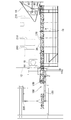
- FIGS. 1 to 8 The work scaffold installation structure in the boiler furnace and the main beam transfer device for the work scaffold according to the first embodiment of the present invention will be described with reference to FIGS. 1 to 8.
- FIG. 1 and FIG. 5 the illustration of the joint material is omitted.
- the main beam structure 10 for work scaffolding of the present embodiment has a main basic configuration of a beam body 20 and a joint member 60 that employ trusses in order to maintain a predetermined rigidity.
- the beam body 20 is a long beam extending linearly from the beam insertion opening 14 of the boiler furnace 12 to the lower part of the water pipe nose portion 16 in the furnace, and is a superheater. It is placed below 210.
- the base end side (outside of the boiler furnace 12) of the main beam structure 10 for the work scaffold (beam body 20) is supported by the main beam transfer device 100 for the work scaffold without being inserted into the beam insertion opening 14, and the water pipe nose portion 16
- the lower tip side of the above is suspended by a suspension rod (suspension means) 80, which will be described later.
- the furnace walls of the boiler fireplace 12 are a vertical pipe wall (vertical water wall) 211 formed in the upper part of the boiler fireplace 12 and a lower end of the vertical pipe wall 211 formed in the lower part of the boiler fireplace 12. It is provided with a spiral pipe wall (spiral water wall) 212 that is continuously suspended from the fireplace.
- the boiler main body including the vertical pipe wall 211 and the spiral pipe wall 212 is suspended from a ceiling girder in a structure (boiler building) composed of steel columns and beams (not shown).
- a plurality of burners 216 are provided side by side in the left-right direction on the spiral tube wall 212 in front of the can.
- the vertical tube wall 211 and the spiral tube wall 212 are composed of a membrane wall.
- the membrane wall is a furnace wall formed by welding and joining water pipes (steel pipes, heat transfer tubes) 213 and fins (steel plates, membrane bars) 214 alternately (see FIG. 5), and a plurality of water pipes 213.
- the membrane wall is arranged so that the water pipe 213 extends in the substantially vertical direction to form the boiler furnace 12.
- a membrane wall is arranged so that the water pipe (not shown) extends in an oblique direction to form a boiler fireplace 12, and each water pipe spirally winds around the boiler fireplace 12. ..
- a plurality of beam insertion openings 14 of the present embodiment are provided side by side (eight in the present embodiment) on the vertical pipe wall 211 in front of the can.
- the beam insertion opening 14 has a rectangular shape (or oval shape) that is long in the vertical direction, and is formed by bending the water pipe 213 as shown in FIG.
- the beam insertion opening 14 is closed openly by a plate-shaped closing body 215.
- the closing body 215 seals the beam insertion opening 14 during boiler operation.
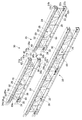
- the beam body 20 is composed of a pair of box beams (main beams) and a truss structure 26.
- the pair of box beams consists of a first box beam 22 and a second box beam 24 having the same shape, and the first and second box beams 22 and 24 are linear from the base end side to the tip end side of the beam body 20. Extend.
- a truss structure 26 is attached between the pair of box beams 22 and 24.
- Each of the first and second box beams 22 and 24 is a metal material (for example, a steel material) having an II-shaped cross section, and the flat plate-shaped first horizontal plate portions 22a and 24a and the flat plate-shaped second horizontal plate portion 22a and 24a.
- the first horizontal plate portions 22a and 24a and the second horizontal plate portions 22b and 24b are vertically separated from each other and are opposed to each other and extend in the longitudinal direction (predetermined direction).
- a pair of vertical plate portions 22c, 24c stand substantially vertically between the first horizontal plate portions 22a, 24a and the second horizontal plate portions 22b, 24b, face each other, and are arranged substantially in parallel in the longitudinal direction (predetermined). Extend in the direction).
- the upper and lower edge portions of the vertical plate portions 22c and 24c are joined to the first horizontal plate portions 22a and 24a and the second horizontal plate portions 22b and 24b by welding, and the vertical plate portions 22c and 24c are the first horizontal plate portions.
- the 22a and 24a are connected to the second horizontal plate portions 22b and 24b.
- the first box beam 22 and the second box beam 24 are vertically laminated so that the first horizontal plate portions 22a and 24a face each other, and a truss structure 26 is provided between the first horizontal plate portions 22a and 24a. ..
- the vertical plate portions 22c and 24c are arranged on the same plane, the truss structure 26 is placed on the upper surface of the first horizontal plate portion 22a of the first box beam 22, and the second box beam is placed on the upper surface of the truss structure 26.
- the first horizontal plate portions 24a of 24 are laminated.
- the truss structure 26 is made of H-shaped steel, but members having other shapes (for example, the truss structure may be made of square steel pipes or the like) first and second box beams 22, 24. Is provided with a reinforcing plate 28 that contacts the first and second horizontal plate portions and the vertical plate portion in the cross-sectional direction. In order to increase the strength of the beam body 20, the reinforcing plates 28 are provided at a plurality of equal intervals along the longitudinal direction of the beam body 20. The reinforcing plate 28 may be omitted.
- the beam body 20 is divided into a plurality of beams (5 divisions as an example in the present embodiment), and the beam units A to E (reference numerals A to E are not shown) are divided into a plurality of beam units A to the tip of the beam unit A by the work scaffolding main beam transport device 100. Then, the beams are connected in the order of B to E. As a result, the boiler fireplace 12 can be easily stored in the building and handled during transportation.
- the beam units B and C are provided with one joint member 60, which will be described later, on one side surface or both sides of the vertical plate portion.
- the beam unit D is provided with two joint members 60 on either one side surface of the vertical plate portion or two on each side. As shown in FIG. 2, the joint member of the beam single unit D having such a configuration is for forming a passage 200 provided in the vicinity of the worker opening 18.
- a connecting means 30 is used to connect each beam alone.
- the connecting means 30 connects the first box beams 22 and the second box beams 24 of the single beam.
- the specific connecting means 30 uses a pair of plate receivers 32, a main beam connecting plate 34, a pair of pins 36 with key grooves, and a key plate 38 to connect the first box beams 22 to each other. ..
- the plate receiver 32 is a pair of plates whose height is substantially the same as the length (height) of the vertical plate portions 22c and 24c and is substantially rectangular in a plan view, and is a pin 36 with a key groove near the center, which will be described later. Is provided with two pin holes 32a into which the above can be inserted.
- the plate receiver 32 is attached in parallel with the vertical plate portion 22c between the brim of the first horizontal plate portion 22a and the second horizontal plate portion 22b centering on the vertical plate portion 22c.
- a plate insertion hole 32b into which the main beam connecting plate 34, which will be described later, can be inserted is formed between the pair of vertical plate portions 22c.
- the plate receiver 32 is provided with a mounting hole 32c for fixing the key plate 38, which will be described later.
- Such plate receivers 32 are attached to both ends of the first box beam 22 of the beam alone.
- the main beam connecting plate 34 has a thickness that can be inserted into the plate insertion hole 32b, a length in the longitudinal direction corresponding to the length of two plate receivers 32 arranged side by side, and a length (height) of the vertical plate portion 22c. A pair of substantially rectangular plates of approximately the same height.
- the main beam connecting plate 34 is provided with a plurality of holes 34a (four places in the example of the figure) at positions facing the pin holes 32a when inserted into the plate insertion holes 32b.
- the key grooved pin 36 is a pin that can be inserted into the pin hole 32a and the hole 34a, and has a brim 36a formed at one end and a key groove 36b formed at the other end.
- the keyway pin 36 is set to a length in which the keyway 36b protrudes from the other plate when the brim 36a comes into contact with one plate of the plate receiver 32 when inserted into the pin hole 32a.
- the key plate 38 includes a pair of recesses 38a that fit into the key groove 36b protruding from the plate of the plate receiver 32. Further, the key plate 38 is provided with a mounting hole 38b at a position facing the mounting hole 32c of the plate receiver 32.
- a main beam connecting plate 34 for connecting the second box beams 24 to each other, a main beam connecting plate 34, a pair of plate receivers 33, a pair of pins 42, and a pair of pin pressing guides 40 are used.
- the main beam connecting plate 34 has the same form as that used for connecting the first box beam 22.
- the plate receiver 33 has substantially the same form as that used for connecting the first box beam 22, and can be applied to the second box beam 24, but the position of the mounting hole 33c is different.
- the mounting holes 33c of the plate receiver 33 are provided so as to sandwich the pin holes 33a in between.
- the pin 42 has a diameter that can be inserted into the pin hole 33a, and is set to a length corresponding to the thickness of the plate receiver 33, in other words, the distance between the outsides of the pair of plates.
- Such a pin 42 is configured so that both ends do not protrude from the main surface of the plate receiver 33 when inserted into the plate receiver 33.
- the pin pressing guide 40 closes the pin hole 33a of the plate receiver 33 from the outside, projects from both main surfaces of the plate receiver 33 in parallel with the horizontal plate portions 24a and 24b of the box beam 24, and extends in the longitudinal direction of the beam body 20. It is a guide extended to.
- the pin pressing guide 40 can be continuously formed along the longitudinal direction of the beam main body 20 together with the guide 50 described later.
- the pin pressing guide 40 is provided with a mounting hole 40a at a position facing the mounting hole 33c of the plate receiver 33, and a fastening means such as a bolt can be inserted and fixed to the plate receiver 33.
- Guides 50 are attached to both main surfaces of the vertical plate portion 24c of the second box beam 24.
- the guide 50 projects from both main surfaces of the vertical plate portion 24c of the second box beam 24 in parallel with the horizontal plate portion, and extends along the longitudinal direction of the beam main body 20.
- the specific configuration of the guide 50 is attached to the guide support piece 52 attached to the reinforcing plate 28.
- the guide support piece 52 is parallel to the horizontal plate portions 24a and 24b from the center of the reinforcing plate 28, and projects in a direction away from the vertical plate portion 24c.
- the guide 50 extends parallel to the vertical plate portion 24c, in other words, along the longitudinal direction of the beam main body 20 on the end surface of the guide support piece 52.
- the guide 50 of the present embodiment projects outward from the horizontal plate portion with respect to the vertical plate portion 24c.
- the joint member 60 is a connecting member that connects a plurality of main beam structures 10 for work scaffolds inserted in the same direction from the beam insertion opening 14 of the boiler furnace 12 in a direction orthogonal to the longitudinal direction.
- the joint member 60 of the present embodiment adopts the truss structure 62 like the beam main body 20, and the fastening metal fittings 63 extending along the longitudinal direction are provided at the four corners of the truss structure 62. ..
- the fastening metal fitting 63 is provided with a hole 64 into which a bolt, a pin, or the like can be inserted.
- one end side is a support portion 66 and the other end side is a connecting portion 68.
- the support portion 66 is attached to a pair of upper and lower support pieces 69 extending from the side surface of the beam body 20 in a direction orthogonal to the longitudinal direction.
- the support piece 69 projects on both side surfaces with the beam body 20 as the center.
- the distance between the upper and lower pair of support pieces 69 is set to be substantially the same as the length of the joint member 60 in the vertical direction (height direction).
- the upper and lower support pieces 69 are provided with holes 69a at both ends at positions overlapping with the holes 64 in a plan view (see FIG. 6).
- the support piece 69 is set so that the left and right projecting lengths when centered on the beam body 20 are substantially the same as or shorter than the projecting length of the guide 50.
- the support portion 66 is attached to the support piece 69 by using a fastening means such as a bolt.
- the joint member 60 is formed so as to be openable and closable in a fan shape from the side surface of the beam main body 20 toward the direction intersecting the longitudinal direction of the beam main body 20 with the support portion 66 as a fulcrum.
- the connecting portion 68 can be connected to the side surface of another adjacent beam main body 20.
- the connecting portion 68 can be fixed to the hole 69a of the support piece 69 in the direction orthogonal to the longitudinal direction of the beam main body 20 by using a fastening means such as a pin, and the beam main bodies 20 can be connected to each other.
- a fastening means such as a pin
- the configuration in which the joint material is provided in the main beam structure 10 for the work scaffold can be changed in design depending on the form of the boiler fireplace.
- a hanging tool 70 is provided on the beam unit A located at the tip of the beam body 20.
- the hanger 70 is composed of a first hanger 72 and a second hanger 74, and is pin-bonded to each other.
- the first hanging metal fitting 72 is provided with a hole 73 that can be connected to the hanging rod 80 of the water pipe nose portion described later.
- the second hanging metal fitting 74 is a metal fitting that is longer than the first hanging metal fitting 72, and has elongated holes 75 formed therein.
- a pin 84 provided in the beam unit A penetrates the elongated hole 75.
- the hanger 70 is housed in an inverted L-shaped storage hole 76 that opens vertically from the upper surface provided at the tip of the beam body 20 (beam unit A) and horizontally opens from the upper surface.
- the pin 84 penetrating the elongated hole 75 is provided near the bending of the storage hole 76.
- the hanging rod 80 is a rod that can be cantilevered and can be arranged in the horizontal direction by pulling up the beam main body 20 whose tip hangs downward by engaging with the hanging tool 70 of the beam main body 20.
- the suspension rod 80 is provided inside the water pipe nose portion 16 above the suspension tool 70.
- An opening 14a is formed on the lower surface of the water pipe nose portion 16 between the suspension rod 80 and the suspension tool 70.
- the suspension rod 80 is a rod that is screwed in the vertical direction with the nut 19a of the support beam 19 provided inside the water pipe nose portion 16.
- a hole 80a is provided so as to be overlapped with the hole 73 of the first hanging metal fitting 72 and the fastening means is inserted and engaged.
- the hanging tool 70 and the hanging rod 80 can be engaged with each other through the opening 14a.
- the opening 14a is formed by bending a water pipe (not shown), and is closed openly by a plate-shaped closing body (not shown). The closing body closes the opening 14a in a sealed manner during boiler operation.
- the second hanging metal fitting 74 fits in the vertical hole of the storage hole 76 at the time of accommodation, and the second hanging metal fitting 74 starts from the second hanging metal fitting 74 in the horizontal hole.
- the first hanging hardware 72 bent at a right angle is housed.
- the engagement with the suspension rod 80 is first pulled upward from the opening 14a of the water pipe nose portion 16 through the hole 73 of the first suspension metal 72 below the first suspension rod 80. Raise 72. Then, the second hanging metal fitting 74 is pulled in the longitudinal direction of the second hanging metal fitting 74. The holes 73 of the first hanging metal fitting 72 and the holes 80a of the hanging rod 80 are aligned with each other and engaged with each other by using a fastening means (FIG. 8 (C)). The nut 19a of the support beam 19 is tightened, and the beam body 20 hanging downward is pulled up and placed in a fixed position, in other words, horizontally.
- the work scaffolding main beam transfer device 100 includes a roller body 120 capable of transporting the work scaffolding main beam structure 10 (beam body 20) from the beam insertion opening 14 of the boiler furnace 12 into the furnace, and a roller surface of the roller body 120.
- a frame body 130 that stands upright on the mounting side of the beam body 20 and surrounds the beam body 20 is provided.
- the frame body 130 is erected vertically from the mounting surface of the beam body 20 so as to surround the beam body 20 in an arch shape on the opening side of the roller body 120.
- the main beam structure 10 for work scaffolding is mounted on the roller main body 120 by the crane 220, and is conveyed by the roller main body 120 along the longitudinal direction of the beam main body 20.
- the beam unit A is placed on the roller body 120 of the main beam transfer device 100 for work scaffolding by using the crane 220. Then, the beam unit A is pushed out toward the beam insertion opening 14 side to open a space. Then, the beam unit B is placed on the roller main body 120 by using the crane 220. The beam unit A and the beam unit B are connected by using the connecting means 30. Plate receivers 32 and 33 and a main beam connecting plate 34 are attached to the beam unit A in advance. Further, plate receivers 32 and 33 are attached to the beam unit B. Then, the main beam connecting plate 34 of the beam unit A is inserted into the plate receivers 32 and 33 of the beam unit B.
- the pin 42 is inserted into the pin hole 33a of the plate receiver 33 on the upper part of the beam unit B, then the pin hole 33a is closed from the outside of the plate receiver 33 with the pin pressing guide 40, and the fastening means is inserted into the mounting hole 33c.
- the pin holding guide 40 is fixed.
- the pin pressing guide 40 can be continuously formed together with the guide 50 along the longitudinal direction of the beam body 20.
- a pin 36 with a key groove is inserted into the pin hole 32a of the plate receiver 32 at the lower part of the beam unit B, and then the recess 38a of the key plate 38 is fitted into the key groove 36b. Then, the fastening means is inserted into the mounting hole 38b and fixed.
- the beam unit A is inserted into the furnace through the beam insertion opening 14.
- the beam unit C to the beam unit E are placed on the roller body 120 of the transport device. Then, the beam main body 20 is formed while being connected by using the connecting means 30 and being conveyed.
- the tip of the beam unit A When the tip of the beam unit A is located below the opening 14a of the water pipe nose portion 16, the tip side of the beam body 20 cantilevered by the main beam transport device 100 for work scaffolding hangs down due to its own weight.
- the wire 82 is passed through the hole 73 of the first hanging metal fitting 72 below the opening 14a and pulled upward to raise and lower the first hanging metal fitting 72. Then, the second hanging metal fitting 74 is pulled up in the longitudinal direction, and the second hanging metal fitting 74 is pulled up.
- the holes 73 of the first hanging metal fitting 72 and the holes 80a of the hanging rod 80 are aligned with each other and engaged with each other by using a fastening means.
- the nut 19a of the support beam 19 is tightened, and the work scaffolding main beam structure 10 hanging downward is pulled up and arranged in a fixed position, in other words, in the horizontal direction.
- the tip side (beam unit A) engages with the suspension rod 80 of the water pipe nose portion 16, and the end side (beam unit E) of the work scaffold main beam transport device 100. It is gripped by a grip (not shown) and fixed in the furnace.
- the first and second box beams 22 in which the upper and lower horizontal plate portions 22a, 22b, 24a, 24b are connected to the main beam constituting the beam main body 20 by a pair of vertical plate portions 22c, 24c. , 24 is used, so that the bending rigidity of the main beam (beam body 20) is increased as compared with the case where H-shaped steel is used for the main beam. Therefore, a work scaffold can be provided in the boiler furnace 12 while reducing the vertical height of the beam insertion opening 14 provided in the furnace wall.
- the bending rigidity of the main beam (beam body 20) is increased, so that the connecting strength by the connecting means 30 can be suppressed to a low level.
- the number of connecting points (the number of pins in this embodiment) can be reduced, and the workability of scaffolding installation is improved.
- FIGS. 9 and 10 The same components as those in the first embodiment are designated by the same reference numerals, and the description thereof will be omitted.
- This embodiment is an example in which the beam insertion opening 14 is provided not in the vertical pipe wall 211 but in the spiral pipe wall 212 for reasons such as the configuration of the boiler fireplace.
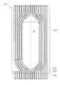
- the water pipe 213 is inclined with respect to the vertical direction and the horizontal direction. Therefore, if a long beam insertion opening 14 is provided in the vertical direction, a part of the water pipe 213 must be bent at a sharp angle. Therefore, it is not possible to provide the beam insertion opening 14 in the vertical direction in terms of thermal flow. Therefore, when the beam insertion opening 14 is provided in the spiral pipe wall 212, the beam insertion opening 14 having a substantially circular shape is provided as shown in FIG.
- the beam body 20 is configured by a single box beam (for example, the first box beam 22 of the first embodiment) without providing a truss structure. There is.
- the beam body 20 is composed of a single box beam 22, the bending rigidity of the beam body 20 is reduced as compared with the first embodiment.
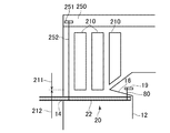
- a second support beam 251 is provided in the penthouse 250 above the boiler fireplace 12, and a second suspension rod (second suspension means) hanging from the second support beam 251 is provided.
- the base end side of the beam body 20 in the boiler furnace 12 is suspended by 252.
- the specific form of suspension by the second suspension rod 252 may be the same as or different from that of the suspension rod 80. Therefore, the beam body 20 is suspended at two locations on both sides of the base end side and the tip end side, and bending deformation of the beam body 20 can be suppressed.
- the present invention is not limited to the above-described embodiment and modification described as an example, and is not limited to the above-described embodiment and the like as long as it does not deviate from the technical idea of the present invention. , Various changes are possible depending on the design and the like.
- a pair of flat plate-shaped horizontal plate portions facing each other in the vertical direction and a pair of horizontal plate portions standing upright facing each other between the pair of horizontal plate portions are formed.
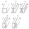
- the box beams 22 and 24 are used as the main beams having a pair of flat plate-shaped vertical plate portions to be connected, main beams having other shapes may be used instead.
- a square steel pipe 300 see FIG. 11 (A)
- a structure in which two channel steels 301 are arranged back to back see FIG. 11 (B)
- two lip channel steels 302 are back to back.
- Arranged structures see FIG. 11 (C)
- structures in which two channel steels 301 are arranged so that the openings face each other see FIG.
- the main beam is composed of a plurality of members as shown in FIGS. 11B to 11E, the two members may be combined.
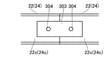
- the connecting means 30 using the pin 42 has been described, but the connecting means for connecting the single beam is not limited to this, and for example, as shown in FIG. 12, the adjacent box beam 22
- the vertical plate portion 22c of the above may be fastened and connected by the splice plate 303 and the bolt 304.
- the rigidity of the connecting portion is improved by adding the splice plate 303 to the main beam connecting plate 34 inserted between the adjacent box beams 22.
Landscapes
- Engineering & Computer Science (AREA)
- Architecture (AREA)
- Mechanical Engineering (AREA)
- Physics & Mathematics (AREA)
- Thermal Sciences (AREA)
- General Engineering & Computer Science (AREA)
- Civil Engineering (AREA)
- Structural Engineering (AREA)
- Conveying And Assembling Of Building Elements In Situ (AREA)
- Movable Scaffolding (AREA)
Abstract
La présente invention concerne une structure d'installation d'un échafaudage de travail permettant d'installer un échafaudage de travail à l'intérieur d'un foyer de chaudière qui comprend : une ouverture d'insertion de poutre disposée dans une paroi de foyer d'un foyer de chaudière ; un corps 20 de poutre qui s'étend linéairement d'un côté base vers un côté pointe, et qui est conçu pour être inséré à travers l'ouverture d'insertion de poutre à partir du côté pointe de façon à être disposée au-dessous d'une section d'extrémité de tuyau d'eau du foyer de chaudière ; et un moyen de suspension qui suspend le côté pointe du corps 20 de poutre. Le corps 20 de poutre a des poutres primaires 22, 24 qui s'étendent linéairement du côté base au côté pointe. Les poutres primaires 22, 24 comprennent : des paires de sections 22a, 22b, 24a, 24b de plaque horizontale ayant une forme de plaque plate et opposées l'une à l'autre tout en étant séparées l'une de l'autre dans la direction verticale ; et des paires de sections 22c, 24c de plaque verticale en forme de plaque qui se tiennent debout tout en s'opposant l'une de l'autre entre les paires de sections 22a, 22b, 24a, 24b de plaque horizontale, de manière à relier les paires de sections 22a, 22b, 24a, 24b de plaque horizontale.
Priority Applications (2)
| Application Number | Priority Date | Filing Date | Title |
|---|---|---|---|
| KR1020227011228A KR20220059515A (ko) | 2019-09-06 | 2020-09-04 | 보일러 화로 내의 작업 발판 설치 구조 |
| PH1/2022/550522A PH12022550522A1 (en) | 2019-09-06 | 2020-09-04 | In-boiler-furnace work platform installation structure |
Applications Claiming Priority (2)
| Application Number | Priority Date | Filing Date | Title |
|---|---|---|---|
| JP2019-163450 | 2019-09-06 | ||
| JP2019163450A JP2021042535A (ja) | 2019-09-06 | 2019-09-06 | ボイラ火炉内の作業足場設置構造 |
Publications (1)
| Publication Number | Publication Date |
|---|---|
| WO2021045221A1 true WO2021045221A1 (fr) | 2021-03-11 |
Family
ID=74853354
Family Applications (1)
| Application Number | Title | Priority Date | Filing Date |
|---|---|---|---|
| PCT/JP2020/033692 Ceased WO2021045221A1 (fr) | 2019-09-06 | 2020-09-04 | Structure d'installation d'échafaudage de travail à l'intérieur d'un foyer de chaudière |
Country Status (4)
| Country | Link |
|---|---|
| JP (1) | JP2021042535A (fr) |
| KR (1) | KR20220059515A (fr) |
| PH (1) | PH12022550522A1 (fr) |
| WO (1) | WO2021045221A1 (fr) |
Cited By (1)
| Publication number | Priority date | Publication date | Assignee | Title |
|---|---|---|---|---|
| JP7161641B1 (ja) | 2022-06-13 | 2022-10-26 | 大 小野 | 吊り足場装置及び吊り足場装置の組立方法 |
Citations (13)
| Publication number | Priority date | Publication date | Assignee | Title |
|---|---|---|---|---|
| JPH04135062A (ja) * | 1990-09-21 | 1992-05-08 | Komai Tekko Inc | 箱形柱状物の角部溶接方法 |
| JPH0849405A (ja) * | 1994-08-09 | 1996-02-20 | Chubu Plant Service:Kk | ボイラ炉内の作業ステージとその構築移動方法 |
| US5771655A (en) * | 1995-12-18 | 1998-06-30 | Canam Steel Corporation | System and method for constructing metal frame structures |
| JP2000303411A (ja) * | 1999-04-23 | 2000-10-31 | Sumitomo Metal Steel Products Inc | ボックス梁型支保工材および橋梁用支保工 |
| JP2002331989A (ja) * | 2001-05-11 | 2002-11-19 | Chuo Build Industry Co Ltd | Lng船防熱工事用足場 |
| JP2003148713A (ja) * | 2001-11-14 | 2003-05-21 | Mitsubishi Heavy Ind Ltd | 水管保護用耐火構造体及びその施工方法 |
| JP2004017844A (ja) * | 2002-06-18 | 2004-01-22 | Chuo Build Industry Co Ltd | Lng船防熱工事用足場 |
| JP2004176253A (ja) * | 2002-11-22 | 2004-06-24 | Nippon Steel Corp | 鋼構造物の補修補強工法 |
| JP2005188782A (ja) * | 2003-12-24 | 2005-07-14 | Ishikawajima Harima Heavy Ind Co Ltd | ボイラマンホールの蓋 |
| JP2015040451A (ja) * | 2013-08-23 | 2015-03-02 | 株式会社日立製作所 | ボイラ火炉内の作業足場用主梁構造、作業足場用主梁搬送装置、及び作業足場の設置方法 |
| JP2015204740A (ja) * | 2014-04-16 | 2015-11-16 | 孟重 関 | 太陽光発電ユニットの設置方法 |
| JP2019060142A (ja) * | 2017-09-27 | 2019-04-18 | 中国電力株式会社 | ボイラ炉内作業足場仮設工法 |
| JP2019078009A (ja) * | 2017-10-20 | 2019-05-23 | 株式会社日立プラントコンストラクション | ボイラ内作業足場、ボイラ水壁の交換装置及びその交換方法 |
Family Cites Families (4)
| Publication number | Priority date | Publication date | Assignee | Title |
|---|---|---|---|---|
| JPS6086305A (ja) * | 1983-10-15 | 1985-05-15 | バブコツク日立株式会社 | ボイラ装置 |
| JP2527309Y2 (ja) * | 1991-08-30 | 1997-02-26 | 中部電力株式会社 | ワーキングステーション吊り下げ装置 |
| JP2012149821A (ja) * | 2011-01-19 | 2012-08-09 | Babcock Hitachi Kk | ボイラ |
| JP5635163B1 (ja) * | 2013-07-29 | 2014-12-03 | 太平電業株式会社 | ボイラ内足場の構築方法 |
-
2019
- 2019-09-06 JP JP2019163450A patent/JP2021042535A/ja active Pending
-
2020
- 2020-09-04 WO PCT/JP2020/033692 patent/WO2021045221A1/fr not_active Ceased
- 2020-09-04 PH PH1/2022/550522A patent/PH12022550522A1/en unknown
- 2020-09-04 KR KR1020227011228A patent/KR20220059515A/ko not_active Ceased
Patent Citations (13)
| Publication number | Priority date | Publication date | Assignee | Title |
|---|---|---|---|---|
| JPH04135062A (ja) * | 1990-09-21 | 1992-05-08 | Komai Tekko Inc | 箱形柱状物の角部溶接方法 |
| JPH0849405A (ja) * | 1994-08-09 | 1996-02-20 | Chubu Plant Service:Kk | ボイラ炉内の作業ステージとその構築移動方法 |
| US5771655A (en) * | 1995-12-18 | 1998-06-30 | Canam Steel Corporation | System and method for constructing metal frame structures |
| JP2000303411A (ja) * | 1999-04-23 | 2000-10-31 | Sumitomo Metal Steel Products Inc | ボックス梁型支保工材および橋梁用支保工 |
| JP2002331989A (ja) * | 2001-05-11 | 2002-11-19 | Chuo Build Industry Co Ltd | Lng船防熱工事用足場 |
| JP2003148713A (ja) * | 2001-11-14 | 2003-05-21 | Mitsubishi Heavy Ind Ltd | 水管保護用耐火構造体及びその施工方法 |
| JP2004017844A (ja) * | 2002-06-18 | 2004-01-22 | Chuo Build Industry Co Ltd | Lng船防熱工事用足場 |
| JP2004176253A (ja) * | 2002-11-22 | 2004-06-24 | Nippon Steel Corp | 鋼構造物の補修補強工法 |
| JP2005188782A (ja) * | 2003-12-24 | 2005-07-14 | Ishikawajima Harima Heavy Ind Co Ltd | ボイラマンホールの蓋 |
| JP2015040451A (ja) * | 2013-08-23 | 2015-03-02 | 株式会社日立製作所 | ボイラ火炉内の作業足場用主梁構造、作業足場用主梁搬送装置、及び作業足場の設置方法 |
| JP2015204740A (ja) * | 2014-04-16 | 2015-11-16 | 孟重 関 | 太陽光発電ユニットの設置方法 |
| JP2019060142A (ja) * | 2017-09-27 | 2019-04-18 | 中国電力株式会社 | ボイラ炉内作業足場仮設工法 |
| JP2019078009A (ja) * | 2017-10-20 | 2019-05-23 | 株式会社日立プラントコンストラクション | ボイラ内作業足場、ボイラ水壁の交換装置及びその交換方法 |
Cited By (2)
| Publication number | Priority date | Publication date | Assignee | Title |
|---|---|---|---|---|
| JP7161641B1 (ja) | 2022-06-13 | 2022-10-26 | 大 小野 | 吊り足場装置及び吊り足場装置の組立方法 |
| JP2023181900A (ja) * | 2022-06-13 | 2023-12-25 | 大 小野 | 吊り足場装置及び吊り足場装置の組立方法 |
Also Published As
| Publication number | Publication date |
|---|---|
| KR20220059515A (ko) | 2022-05-10 |
| JP2021042535A (ja) | 2021-03-18 |
| PH12022550522A1 (en) | 2023-03-20 |
Similar Documents
| Publication | Publication Date | Title |
|---|---|---|
| JP6172632B2 (ja) | ボイラ火炉内の作業足場用主梁構造、作業足場用主梁搬送装置、及び作業足場の設置方法 | |
| US20190226198A1 (en) | Framework Module for use in Modular Building Construction | |
| AU2018282313A1 (en) | Assembled building structure with combination of steel structure and concrete structure and construction method thereof | |
| CA2650684A1 (fr) | Traverse de suspension de materiel mecanique | |
| WO2021045221A1 (fr) | Structure d'installation d'échafaudage de travail à l'intérieur d'un foyer de chaudière | |
| JP6038710B2 (ja) | 配管又はラック支持具 | |
| CN108505621A (zh) | 内套筒式钢框架梁柱连接装置 | |
| CN104500843A (zh) | 一种用于水平钢管的支架系统 | |
| JP7373115B2 (ja) | 柱梁接合構造及び建物 | |
| KR20090034510A (ko) | 커튼월 고정용 브래킷 | |
| CN212271481U (zh) | 墙面铝板系统 | |
| JP7194532B2 (ja) | 鋼部材の補強構造及び鋼部材の補強方法 | |
| JP2018009366A (ja) | 壁パネルの連結構造 | |
| CN116145970A (zh) | 一种斜向桁架梁下转换层的安装施工方法 | |
| JP7272800B2 (ja) | 耐震天井構造 | |
| JP7208028B2 (ja) | 耐震天井構造の施工方法 | |
| JP6537695B1 (ja) | 角形鋼材連結プレート及び軽量鉄骨構造の建築物 | |
| CN221856169U (zh) | 爬架脚手板支撑件 | |
| CN113502916B (zh) | 一种型材快速锁紧装置及其施工方法 | |
| CN219491322U (zh) | 一种房建梁柱快速连接结构 | |
| CN216739653U (zh) | 一种基坑围护用的锯齿式围檩部件 | |
| SU1165756A1 (ru) | Узел опирани металлической фермы на колонну | |
| JP4691202B1 (ja) | 建物の補強構造 | |
| JP2025002993A (ja) | 仮設足場およびその設置方法 | |
| JP7329770B2 (ja) | 張り出しパネルユニット及び張り出しパネル構造 |
Legal Events
| Date | Code | Title | Description |
|---|---|---|---|
| 121 | Ep: the epo has been informed by wipo that ep was designated in this application |
Ref document number: 20860816 Country of ref document: EP Kind code of ref document: A1 |
|
| NENP | Non-entry into the national phase |
Ref country code: DE |
|
| ENP | Entry into the national phase |
Ref document number: 20227011228 Country of ref document: KR Kind code of ref document: A |
|
| 122 | Ep: pct application non-entry in european phase |
Ref document number: 20860816 Country of ref document: EP Kind code of ref document: A1 |