WO2021048992A1 - 前処理装置、判定システム、前処理方法および前処理プログラム - Google Patents
前処理装置、判定システム、前処理方法および前処理プログラム Download PDFInfo
- Publication number
- WO2021048992A1 WO2021048992A1 PCT/JP2019/035988 JP2019035988W WO2021048992A1 WO 2021048992 A1 WO2021048992 A1 WO 2021048992A1 JP 2019035988 W JP2019035988 W JP 2019035988W WO 2021048992 A1 WO2021048992 A1 WO 2021048992A1
- Authority
- WO
- WIPO (PCT)
- Prior art keywords
- determination
- polygon
- outside
- internal
- rotation
- Prior art date
- Legal status (The legal status is an assumption and is not a legal conclusion. Google has not performed a legal analysis and makes no representation as to the accuracy of the status listed.)
- Ceased
Links
Images












Classifications
-
- G—PHYSICS
- G06—COMPUTING OR CALCULATING; COUNTING
- G06T—IMAGE DATA PROCESSING OR GENERATION, IN GENERAL
- G06T17/00—Three-dimensional [3D] modelling for computer graphics
- G06T17/05—Geographic models
-
- G—PHYSICS
- G06—COMPUTING OR CALCULATING; COUNTING
- G06T—IMAGE DATA PROCESSING OR GENERATION, IN GENERAL
- G06T19/00—Manipulating three-dimensional [3D] models or images for computer graphics
- G06T19/20—Editing of three-dimensional [3D] images, e.g. changing shapes or colours, aligning objects or positioning parts
-
- G—PHYSICS
- G06—COMPUTING OR CALCULATING; COUNTING
- G06T—IMAGE DATA PROCESSING OR GENERATION, IN GENERAL
- G06T17/00—Three-dimensional [3D] modelling for computer graphics
- G06T17/20—Finite element generation, e.g. wire-frame surface description, tesselation
-
- G—PHYSICS
- G06—COMPUTING OR CALCULATING; COUNTING
- G06T—IMAGE DATA PROCESSING OR GENERATION, IN GENERAL
- G06T2210/00—Indexing scheme for image generation or computer graphics
- G06T2210/12—Bounding box
-
- G—PHYSICS
- G06—COMPUTING OR CALCULATING; COUNTING
- G06T—IMAGE DATA PROCESSING OR GENERATION, IN GENERAL
- G06T2210/00—Indexing scheme for image generation or computer graphics
- G06T2210/21—Collision detection, intersection
-
- G—PHYSICS
- G06—COMPUTING OR CALCULATING; COUNTING
- G06T—IMAGE DATA PROCESSING OR GENERATION, IN GENERAL
- G06T2219/00—Indexing scheme for manipulating 3D models or images for computer graphics
- G06T2219/20—Indexing scheme for editing of 3D models
- G06T2219/2016—Rotation, translation, scaling
Definitions
- the present invention relates to a pretreatment device, a determination system, a pretreatment method, and a pretreatment program.
- the polygon inside / outside judgment technology determines whether specific coordinates are included inside a specific polygon.
- the polygon inside / outside determination technique is applied, for example, when determining whether the coordinates of a geographical vehicle or the like are included in a polygon representing a road area.
- determination techniques For example, as a conventional polygon inside / outside determination technique, there are determination techniques based on the Crossing Number method and the Winding Number method (see, for example, Non-Patent Document 1). These determination techniques determine whether or not the coordinates are included inside the polygon by aggregating the positional relationship between all the sides of the polygon to be determined and the coordinates of the determination target.
- This bounding container is a figure that includes a polygon to be determined.
- This technology is a technology that reduces the average processing time by selecting a figure that can execute internal / external judgment at high speed as a bounding container and applying the Crossing Number method or Winding Number method only to the coordinates included in the bounding container. is there.
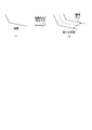
- a rectangle MRR: Minimal Bounding Rectangle
- MRR Minimal Bounding Rectangle
- this polygon When the polygon inside / outside judgment technology is applied to determine whether or not the road area includes geographical vehicles, this polygon has a large number of vertices and has an elongated shape in order to represent the road area. It has the characteristic of being.
- the Crossing Number method and the Winding Number method have the property that the processing time is proportional to the number of vertices, there is a problem that the processing time becomes long when the judgment is made for a polygon having a large number of vertices.
- the MBR has the property of including a large area outside the polygon for the elongated polygon, the effect of shortening the average processing time can be obtained when the determination is performed for the polygon having the elongated shape. There is a problem that it is hard to come out.
- the present invention has been made in view of the above, and an object of the present invention is to provide a preprocessing apparatus, a determination system, a preprocessing method, and a preprocessing program capable of shortening the processing time required for polygon inside / outside determination processing. And.
- the preprocessing apparatus of the present invention is used as a preprocessing of the determination process for determining whether the coordinates to be determined exist inside or outside the polygon for inside / outside determination.
- the reduction unit that acquires the coordinate information of each vertex of the polygon for internal / external judgment and reduces the vertices of the polygon for internal / external judgment, and the coordinate information of each vertex of the polygon after the reduction unit reduces the vertices. It is characterized by having an output unit that outputs to a device that performs determination processing.
- the determination system of the present invention includes a determination device that determines whether or not the coordinates to be determined exist inside or outside the polygon for inside / outside determination, and a first preprocessing device that performs preprocessing of the determination process.
- the first preprocessing device acquires the coordinate information of each vertex of the polygon for internal / external determination, and performs the first preprocessing to reduce the vertices of the polygon for internal / external determination.
- the determination device has a unit and an output unit that outputs the reduced polygon information which is the coordinate information of each vertex of the polygon after the reduction unit reduces the vertices, and the determination device uses the information after the preprocessing. , It is characterized in that it is determined whether or not the coordinates to be determined exist inside or outside the polygon for inside / outside determination.
- the pre-processing method of the present invention is a pre-processing method performed by the pre-processing apparatus, and is used as a pre-processing for determining whether or not the coordinates to be determined are inside or outside the polygon for determining inside or outside.
- the process of acquiring the coordinate information of each vertex of the polygon for internal / external judgment and reducing the vertices of the polygon for internal / external judgment, and the judgment processing of the coordinate information of each vertex of the polygon after the number of vertices is reduced. It is characterized by including a process of outputting to a device to be performed.
- the preprocessing program of the present invention provides coordinate information of each vertex of the polygon for internal / external determination as a preprocessing for determination processing for determining whether the coordinates to be determined exist inside or outside the polygon for internal / external determination. And the step of reducing the vertices of the polygon for internal / external judgment and the step of outputting the coordinate information of each vertex of the polygon after the vertices are reduced to the device that performs the judgment processing are executed on the computer. Let me.
- the processing time required for the polygon inside / outside determination processing can be shortened.
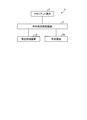
- FIG. 1 is a block diagram showing an example of the configuration of the determination system according to the first embodiment.
- FIG. 2 is a block diagram showing an example of the configuration of the vertex reduction device shown in FIG.
- FIG. 3 is a diagram showing a list of data structures of polygon information.
- FIG. 4 is a block diagram showing an example of the configuration of the determination device shown in FIG.
- FIG. 5 is a diagram showing a list of data configurations of coordinate information.
- FIG. 6 is a diagram illustrating a vertex reduction process.
- FIG. 7 is a sequence diagram illustrating a processing procedure of the determination process by the determination system shown in FIG.
- FIG. 8 is a flowchart showing a processing procedure of the vertex reduction processing shown in FIG. 7.
- FIG. 7 is a sequence diagram illustrating a processing procedure of the determination process by the determination system shown in FIG.
- FIG. 8 is a flowchart showing a processing procedure of the vertex reduction processing shown in FIG. 7.
- FIG. 7 is a sequence diagram
- FIG. 9 is a flowchart showing a processing procedure of the inside / outside determination process shown in FIG. 7.
- FIG. 10 is a block diagram showing an example of the configuration of the determination system according to the second embodiment.
- FIG. 11 is a block diagram showing an example of the configuration of the rotating device shown in FIG.
- FIG. 12 is a diagram illustrating the rotation process.
- FIG. 13 is a sequence diagram illustrating a processing procedure of the determination process by the determination system shown in FIG.
- FIG. 14 is a flowchart showing a processing procedure of the rotation process shown in FIG.
- FIG. 15 is a block diagram showing an example of the configuration of the determination system according to the third embodiment.
- FIG. 16 is a block diagram showing an example of the configuration of the dividing device shown in FIG. FIG.
- FIG. 17 is a diagram illustrating a division process.
- FIG. 18 is a sequence diagram illustrating a processing procedure of the determination process by the determination system shown in FIG.
- FIG. 19 is a flowchart showing a processing procedure of the division processing shown in FIG.
- FIG. 20 is a block diagram showing an example of the configuration of the determination system according to the fourth embodiment.
- FIG. 21 is a sequence diagram illustrating a processing procedure of the determination process by the determination system shown in FIG. 20.
- FIG. 22 is a sequence diagram illustrating a processing procedure of the determination process in the first modification of the fourth embodiment.
- FIG. 23 is a sequence diagram for explaining the processing procedure of the determination process in the second modification of the fourth embodiment.
- FIG. 21 is a sequence diagram illustrating a processing procedure of the determination process by the determination system shown in FIG. 20.
- FIG. 22 is a sequence diagram illustrating a processing procedure of the determination process in the first modification of the fourth embodiment.
- FIG. 23 is a sequence diagram for explaining the processing procedure of
- FIG. 24 is a sequence diagram illustrating a processing procedure of the determination process according to the third modification of the fourth embodiment.
- FIG. 25 is a diagram illustrating an experimental model.
- FIG. 26 is a diagram for explaining the PIP processing time in the case where the inside / outside determination is performed after the vertex reduction processing is performed and the case where the inside / outside determination is performed without executing the preprocessing.
- FIG. 27 is a diagram illustrating the division process performed in the verification.
- FIG. 28 is a diagram for explaining the PIP processing time in the case where the inside / outside determination is performed after the division processing is performed and the case where the inside / outside determination is performed without executing the preprocessing.
- FIG. 29 is a diagram illustrating the rotation process performed in the verification.
- FIG. 29 is a diagram illustrating the rotation process performed in the verification.
- FIG. 30 is a diagram for explaining the PIP processing time in the case where the inside / outside determination is performed after the rotation processing is performed and the case where the inside / outside determination is performed without executing the preprocessing.
- FIG. 31 is a diagram illustrating another application example of the determination system according to the first to fourth embodiments.
- FIG. 32 is a diagram showing an example of a computer in which a vertex reduction device, a determination device, a rotation device, and a division device are realized by executing a program.
- the first embodiment will be described.
- the vertices of the polygon for internal / external determination are reduced before the internal / external determination process for determining whether the coordinates to be determined exist inside or outside the polygon for internal / external determination.
- the processing time required for the judgment processing is shortened.
- FIG. 1 is a block diagram showing an example of the configuration of the determination system according to the first embodiment.
- the determination system 1 according to the first embodiment includes a client terminal 2, an inside / outside determination control device 3, a vertex reduction device 10, and a determination device 20.
- the client terminal 2 and the inside / outside determination control device 3 are connected via a network or the like.
- the inside / outside determination control device 3, the vertex reduction device 10, and the determination device 20 are connected via a network or the like.
- the client terminal 2 is a terminal device used by the user of the determination system 1.
- the client terminal 2 transmits the coordinate information D20 of the coordinates to be determined and the polygon information D10 which is the coordinate information of each vertex of the polygon for internal / external determination to the internal / external determination control device 3 to make a determination request. ..
- the inside / outside determination control device 3 is a server device that controls processing in the vertex reduction device 10 and the determination device 20. Upon receiving a judgment request from the client terminal 2, the inside / outside judgment control device 3 determines whether the coordinates to be judged exist inside or outside the polygon for inside / outside judgment (judgment processing). Is executed, and the determination result is returned to the client terminal 2. Further, in the first embodiment, the inside / outside determination control device 3 causes the vertex reduction device 10 to execute the preprocessing of the inside / outside determination process before the determination device 20 executes the inside / outside determination process.
- the vertex reduction device 10 receives the polygon information D10 from the inside / outside determination control device 3 and executes preprocessing for reducing the vertices of the polygon for inside / outside determination.
- the vertex reduction device 10 outputs the reduced polygon information D11, which is the coordinate information of each vertex of the polygon after the number of vertices is reduced, to the inside / outside determination control device 3.
- the determination device 20 performs an inside / outside determination process for determining whether the coordinates to be determined exist inside or outside the polygon for inside / outside determination. At this time, the determination device 20 performs internal / external determination processing based on the reduced polygon information D11 and the coordinate information D20 of the coordinates to be determined. The determination device 20 outputs determination information including the determination result to the inside / outside determination control device 3.
- FIG. 2 is a block diagram showing an example of the configuration of the vertex reduction device 10 shown in FIG.
- the vertex reduction device 10 includes a communication unit 11, a storage unit 12, and a control unit 13.
- the communication unit 11 is a communication interface for transmitting and receiving various information to and from other devices connected via a network or the like.
- the communication unit 11 is realized by a NIC (Network Interface Card) or the like, and communicates between another device and the control unit 13 (described later) via a telecommunication line such as a LAN (Local Area Network) or the Internet.
- NIC Network Interface Card
- telecommunication line such as a LAN (Local Area Network) or the Internet.
- the communication unit 11 receives the polygon information D10 from the inside / outside determination control device 3 via the network. Further, the communication unit 11 transmits the reduced polygon information D11 to the inside / outside determination control device 3.
- the storage unit 12 is realized by a semiconductor memory element such as a RAM (Random Access Memory) or a flash memory (Flash Memory), or a storage device such as a hard disk or an optical disk, and is a processing program or a processing program for operating the vertex reduction device 10. Data used during execution of is stored.
- the storage unit 12 stores the polygon information D10 and the reduced polygon information D11.
- the polygon information D10 is the coordinate information of each vertex of the polygon for determining inside and outside.
- the polygon information D10 is transmitted from the inside / outside determination control device 3.
- FIG. 3 is a diagram showing a list of data structures of polygon information D10.
- the polygon information D10 is a list of coordinates of the vertices of the polygon for internal / external determination. For example, when the polygon for internal / external determination has 100 vertices, 100 sets of polygons are used. Has coordinates.
- the reduced coordinate information D11 is the coordinate information of each vertex of the polygon whose vertices are reduced by the processing of the vertex reduction unit 131 (described later) for each vertex of the polygon for internal / external determination.
- the reduced coordinate information D11 is, for example, a coordinate list of each vertex of the polygon whose vertices are reduced from 100 to 60.
- the control unit 13 controls the entire vertex reduction device 10.
- the control unit 13 is, for example, an electronic circuit such as a CPU (Central Processing Unit) and an MPU (Micro Processing Unit), and an integrated circuit such as an ASIC (Application Specific Integrated Circuit) and an FPGA (Field Programmable Gate Array). Further, the control unit 13 has an internal memory for storing programs and control data that define various processing procedures, and executes each process using the internal memory. Further, the control unit 13 functions as various processing units by operating various programs.
- the control unit 13 has a vertex reduction unit 131 (reduction unit).
- the vertex reduction unit 131 acquires the polygon information D10 as a preprocessing of the inside / outside determination process, and reduces the vertices of the polygon for inside / outside determination.
- the vertex reduction unit 131 performs a process of thinning out the vertices of the polygon for determining inside / outside at appropriate intervals.
- the vertex reduction unit 131 realizes the vertex reduction process by using a Ramer-Douglas-Peucker algorithm (see, for example, Reference 1).
- the vertex reduction unit 131 stores the reduced coordinate information D11, which is the coordinate information of each vertex of the polygon whose vertices have been reduced by the vertex reduction processing for each vertex of the polygon for internal / external determination, in the storage unit 12, and also stores the coordinate information D11. This information is output to the inside / outside determination control device 3 via the communication unit 11.
- FIG. 4 is a block diagram showing an example of the configuration of the determination device 20 shown in FIG.
- the determination device 20 includes a communication unit 21, a storage unit 22, and a control unit 23.
- the communication unit 21 is a communication interface for transmitting and receiving various information to and from other devices connected via a network or the like, and is realized by a NIC or the like, and is another device via a telecommunication line such as a LAN or the Internet. Communication is performed between the device and the control unit 23 (described later).
- the communication unit 21 receives the reduced polygon information D11 and the coordinate information D20 as the coordinate information of each vertex of the polygon for inside / outside determination from the inside / outside determination control device 3 via the network. Further, the communication unit 21 transmits the determination result of the inside / outside determination unit 231 (described later) to the inside / outside determination control device 3.
- the storage unit 22 is realized by a semiconductor memory element such as a RAM or a flash memory, or a storage device such as a hard disk or an optical disk, and contains a processing program that operates the determination device 20, data used during execution of the processing program, and the like. It will be remembered.
- the storage unit 22 stores the reduced polygon information D11 and the coordinate information D20.
- the coordinate information D20 is the coordinate information of the coordinates to be determined.
- the coordinate information D20 is transmitted from the inside / outside determination control device 3.
- FIG. 5 is a diagram showing a list of data configurations of the coordinate information D20. As shown in FIG. 5, the coordinate information D20 indicates the longitude and latitude of the coordinates to be determined.
- the control unit 23 controls the entire vertex reduction device 10.
- the control unit 23 is, for example, an electronic circuit such as a CPU or MPU, or an integrated circuit such as an ASIC or FPGA. Further, the control unit 23 has an internal memory for storing programs and control data that define various processing procedures, and executes each process using the internal memory. Further, the control unit 23 functions as various processing units by operating various programs. The control unit 23 performs the inside / outside determination unit 231.
- the inside / outside determination unit 231 performs an inside / outside determination process for determining whether the coordinates to be determined exist inside or outside the polygon for inside / outside determination based on the reduced polygon information D11 and the coordinate information D20.
- the internal / external determination unit 231 executes a detailed determination by the Crossing Number method or the Winding Number method after the simple determination by the MBR.
- FIG. 6 is a diagram illustrating a vertex reduction process.
- FIG. 6 (1) shows a polygon P10 for determining inside / outside before the vertex reduction process
- FIG. 6 (2) shows a polygon P11 after the vertex reduction process.
- FIG. 6 also shows MBR40, coordinates C1, C2, and C3 to be determined.
- the polygon P10 shown in FIG. 6 (1) has 16 vertices.
- the vertex reduction unit 131 reduces the vertices of the polygon P10 by using the algorithm of Ramer-Douglas-Peucker.
- Ramer-Douglas-Peucker's algorithm (A) plots the start and end points of the route, (B) examines the distance between the straight line connecting the plot targets and each point between them, and at points that are more than the allowable distance. , Find the farthest point, (C) make it a new plot target, repeat the processes of (B) and (C) recursively, and (D) end if there is no point more than ⁇ away. Is.
- the vertex reduction unit 131 is a polygon in which the number of vertices is reduced to 10 as compared with the polygon P10 in which the number of vertices is 16. Generate P11. Then, the determination device 20 performs the determination process using the polygon P11 as a polygon for internal / external determination.
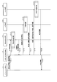
- FIG. 7 is a sequence diagram illustrating a processing procedure of the determination process by the determination system 1 shown in FIG.
- the client terminal 2 transmits the coordinate information D20 of the coordinates to be determined and the polygon information D10 which is the coordinate information of each vertex of the polygon for internal / external determination to the internal / external determination control device 3 to request the determination. (Step S1).
- the inside / outside determination control device 3 Upon receiving the determination request, transmits the polygon information D10 to the vertex reduction device 10 (step S2), and causes the preprocessing to be executed.
- the vertex reduction device 10 executes a vertex reduction process for reducing the vertices of the polygon for internal / external determination based on the polygon information D10 received from the internal / external determination control device 3 (step S3), and after reduction.
- the polygon information D11 is transmitted to the inside / outside determination control device 3 (step S4).
- the inside / outside determination control device 3 transmits the reduced polygon information D11 and the coordinate information D20 to the determination device 20 (step S5), and executes the inside / outside determination process.
- the inside / outside determination control device 3 performs an inside / outside determination process (step S6) based on the reduced polygon information D11 and the coordinate information D20, and transmits the determination information to the inside / outside determination control device 3 (step S7).
- the inside / outside determination control device 3 transmits the determination information to the client terminal 2 (step S8).
- FIG. 8 is a flowchart showing a processing procedure of the vertex reduction processing shown in FIG. 7.
- the vertex reduction device 10 when the vertex reduction device 10 receives the input of the polygon information D10 by the inside / outside determination control device 3 (step S11), the vertex reduction device 10 reduces the vertices of the polygon for inside / outside determination (step S12).
- the vertex reduction device 10 generates polygon information D11 after reduction, outputs the polygon information D11 to the inside / outside determination control device 3 (step S13), and ends the vertex reduction process.
- FIG. 9 is a flowchart showing a processing procedure of the inside / outside determination process shown in FIG. 7.
- the determination device 20 performs a simple determination process for determining whether or not the coordinates of the determination target are inside the MBR (step S21).
- the determination device 20 determines that the coordinates to be determined are not inside the MBR (step S21: No)
- the determination device 20 determines that the coordinates are outside the polygon for inside / outside determination (“false”) (step S22). ..
- the determination device 20 determines that the coordinates to be determined are inside the MBR (step S21: Yes)
- the determination device 20 performs detailed determination by the Crossing Number method or the Winding Number method.
- the determination device 20 sets the polygon shown in the reduced polygon information D11 as the polygon to be determined inside and outside, and determines whether or not the coordinates of the determination target are inside the polygon for determining inside and outside (step). S23).
- step S23 When the determination device 20 determines that the coordinates of the determination target are not inside the polygon for inside / outside determination (step S23: No), the process proceeds to step S22, and the coordinates are outside the polygon for inside / outside determination ("" "False") is determined (step S22).
- step S23 when the determination device 20 determines that the coordinates of the determination target are inside the polygon for determining inside / outside (step S23: Yes), the coordinates are inside the polygon for determining inside / outside ("" It is determined that "true") (step S24).
- the determination device 20 executes the processes of steps S21 to S24 for each of the coordinates of the determination target, and transmits the determination information associated with the determination result for each of the coordinates of the determination target to the internal / external determination control device 3.
- the preprocessing for reducing the vertices of the polygon for internal / external determination is performed, and the polygon internal / external determination processing for each coordinate is performed using the polygon with the reduced vertices. Therefore, in the first embodiment, since the detailed determination is executed based on the polygon whose vertices are reduced during the detailed determination process, it is compared with the case where the detailed determination is performed for the initial polygon for internal / external determination. Therefore, the processing time of the detailed determination process can be shortened.
- the first embodiment is applied to a polygon representing a road area having a large number of vertices, particularly when it is applied to determine whether the coordinates of a geographical vehicle or the like are included in the polygon representing the road area. Since the detailed determination process is performed after reducing the number of vertices in advance, the processing time of the determination process can be increased.
- the inside / outside determination control device 3 causes the vertex reduction device 10 to reduce the vertices of the polygon for inside / outside determination in advance and stores the vertices in the storage area of the inside / outside determination control device 3. It may be read out at the time of internal / external determination and transmitted to the determination device 20.
- the inside / outside judgment processing is performed by rotating the polygon for inside / outside judgment and the coordinates of the judgment target to reduce the area of the MBR including the rotated polygon. Reduce the processing time required for.
- FIG. 10 is a block diagram showing an example of the configuration of the determination system according to the second embodiment.
- the determination system 201 according to the second embodiment has a rotating device 210 (pretreatment device, first pretreatment device) instead of the vertex reduction device 10 as compared with the determination system 1 shown in FIG. ).
- the rotating device 210 receives the polygon information D10 and the coordinate information D20 from the inside / outside determination control device 3, and executes a preprocessing for rotating the polygon for inside / outside determination and the coordinates of the determination target.
- the rotating device 210 sends the post-rotation polygon information D12, which is the coordinate information of each vertex of the rotated polygon, and the post-rotation coordinate information D22, which is the coordinate information of the coordinates to be determined after the rotation, to the inside / outside determination control device 3. Output.
- the determination device 20 determines whether the coordinates of the determination target after rotation exist inside or outside the polygon for internal / external determination after rotation based on the polygon information D12 after rotation and the coordinate information D22 after rotation. Judgment processing is performed.
- FIG. 11 is a block diagram showing an example of the configuration of the rotating device 210 shown in FIG.
- the rotating device 210 includes a communication unit 211 (output unit, first output unit), a storage unit 212, and a control unit 213.
- the communication unit 211 has the same function as the communication unit 11 in the vertex reduction device 10.
- the communication unit 211 receives the polygon information D10 and the coordinate information D20 from the inside / outside determination control device 3 via the network. Further, the communication unit 211 controls the inside / outside determination of the polygon for inside / outside determination and the post-rotation polygon information D12 and the post-rotation coordinate information D22 generated by the rotation processing by the rotation unit 2131 (described later) with respect to the coordinates to be determined. It is transmitted to the device 3.
- the storage unit 212 has the same function as the storage unit 12 in the vertex reduction device 10.
- the storage unit 312 stores polygon information D10, coordinate information D20, post-rotation polygon information D12, and post-rotation coordinate information D22.
- the control unit 213 has the same function as the control unit 13 in the vertex reduction device 10.
- the control unit 213 has a rotating unit 2131.
- the rotating unit 2131 acquires polygon information D10 and coordinate information D20 as preprocessing of the inside / outside determination processing, and rotates the polygon for inside / outside determination and the coordinates of the determination target.
- the rotation unit 2131 realizes the rotation process by using an algorithm for deriving the rotation angle (see, for example, Reference 2).
- Reference 2 "Minimum-Area Rectangle Containing a Set of Points", [online], [Search on August 23, 1st year of Reiwa], Internet ⁇ URL: https://www.geometrictools.com/Documentation/MinimumAreaRectangle. pdf >
- the rotating unit 2131 stores the post-rotation polygon information D12 and the post-rotation coordinate information D22 in the storage unit 212, and outputs these information to the internal / external determination control device 3 via the communication unit 211.
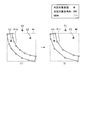
- FIG. 12 is a diagram illustrating the rotation process.
- FIG. 12 (1) shows the polygon P10 for internal / external determination before rotation processing and the coordinates C1, C2, C3 to be determined
- FIG. 12 (2) shows the polygon P11 after rotation processing and after rotation.
- the coordinates C12, C22, and C32 of are shown.
- FIG. 12 also shows an MBR 40 before the rotation process and an MBR 42 set after the rotation process.
- the MBR40 with respect to the polygon P10 is a substantially square including the coordinates C1 and C2.
- the rotating unit 2131 appropriately rotates the polygon P10 and the coordinates C1, C2, and C3 to be determined by using the algorithm for deriving the rotation angle.
- the MBR 42 having a smaller area than the MBR 40 can be set as the MBR including the polygon P12 for determining the inside / outside after rotation. Further, the coordinate C22 to be determined is located outside the new MBR42 due to rotation, and the determination is completed only by a simple determination.
- the coordinates determined to be outside the polygon for internal / external determination increase only by the simple determination, and the detailed determination is made. Can be reduced in the number of executions.
- the coordinates to be determined in detail are only the coordinates C32 among the coordinates C12, C22, and C23.
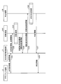
- FIG. 13 is a sequence diagram illustrating a processing procedure of the determination process by the determination system 201 shown in FIG.
- Step S31 shown in FIG. 13 is the same process as step S1 shown in FIG. 7.
- the inside / outside determination control device 3 Upon receiving the determination request, the inside / outside determination control device 3 transmits the polygon information D10 and the coordinate information D20 to the rotating device 210 (step S32), and causes the preprocessing to be executed.
- the rotating device 210 executes a rotation process of rotating the polygon for internal / external determination and the coordinates of the determination target based on the polygon information D10 and the coordinate information D20 received from the internal / external determination control device 3 (Ste S33), the post-rotation polygon information D12 and the post-rotation coordinate information D22 are transmitted to the inside / outside determination control device 3 (step S34).
- the inside / outside determination control device 3 transmits the post-rotation polygon information D12 and the post-rotation coordinate information D22 to the determination device 20 (step S35), and causes the inside / outside determination process to be executed.
- the determination device 20 determines whether or not the coordinates of the determination target after rotation exist inside or outside the polygon for internal / external determination after rotation, based on the polygon information D12 after rotation and the coordinate information D22 after rotation.
- the inside / outside determination process is performed (step S36).
- the inside / outside determination process is the same process as step S6 shown in FIG. Further, steps S37 and S38 shown in FIG. 13 are the same processes as steps S7 and S8 shown in FIG.
- FIG. 14 is a flowchart showing a processing procedure of the rotation process shown in FIG.
- the rotating device 210 when the rotating device 210 receives the input of the polygon information D10 and the coordinate information D20 by the inside / outside determination control device 3 (step S41), the rotating device 210 rotates the polygon for inside / outside determination and the coordinates of the determination target. (Step S42). The rotating device 210 generates the post-rotation polygon information D12 and the post-rotation coordinate information D22, outputs the information to the inside / outside determination control device 3 (step S43), and ends the rotation process.
- the polygon for internal / external determination and the coordinates of the determination target are preprocessed to rotate, and the MBR whose area is reduced as compared with that before the rotation is used to determine the determination target after rotation. Performs polygon inside / outside judgment processing for each coordinate of. Therefore, in the second embodiment, since the simple determination is performed using the MBR with the reduced area, the coordinates determined to be outside the polygon for internal / external determination increase only by the simple determination. As a result, in the second embodiment, the number of executions of the detailed determination can be reduced, and the entire processing time of the determination process can be shortened.
- the inside / outside determination control device 3 rotates the polygon for inside / outside determination and the coordinates of the determination target in advance with respect to the rotation device 210, and stores the inside / outside determination control device 3 in the storage area. It may be stored, read at the time of internal / external determination, and transmitted to the determination device 20.
- the third embodiment Before the inside / outside judgment processing by the judgment device, the polygon for inside / outside judgment is divided into a plurality of polygons having a small area, and the area of each MBR with respect to the divided polygon is reduced. , Shorten the processing time required for internal / external judgment processing.
- FIG. 15 is a block diagram showing an example of the configuration of the determination system according to the third embodiment.
- the determination system 301 according to the third embodiment has a division device 310 (second pretreatment device) instead of the vertex reduction device 10 as compared with the determination system 1 shown in FIG.
- the dividing device 310 receives the polygon information D10 from the inside / outside determination control device 3 and executes preprocessing for dividing the polygon for inside / outside determination.
- the dividing device 310 divides the polygon for internal / external determination, and outputs the divided polygon information D13 including the coordinate information of each vertex of each divided polygon to the internal / external determination control device 3.
- the determination device 20 determines whether the coordinates of the determination target exist inside or outside the polygon for internal / external determination for each polygon for internal / external determination after division. Performs internal / external determination processing for determination.
- FIG. 16 is a block diagram showing an example of the configuration of the dividing device 310 shown in FIG.
- the dividing device 310 includes a communication unit 311 (second output unit), a storage unit 312, and a control unit 313.
- the communication unit 311 has the same function as the communication unit 11 in the vertex reduction device 10.
- the communication unit 311 receives the polygon information D10 from the inside / outside determination control device 3 via the network. Further, the communication unit 311 transmits the post-division polygon information D13 generated by the division process by the division unit 3131 (described later) for the polygon for internal / external determination to the internal / external determination control device 3.
- the storage unit 312 has the same function as the storage unit 12 in the vertex reduction device 10.
- the storage unit stores the polygon information D10 and the divided polygon information D13.
- the control unit 313 has the same function as the control unit 13 in the vertex reduction device 10.
- the control unit 313 has a division unit 3131.
- the dividing unit 3131 acquires the polygon information D10 as a preprocessing of the inside / outside determination process, and divides the polygon for inside / outside determination into a plurality of polygons. For example, the division unit 3131 realizes the division process by using an algorithm for dividing a polygon into triangles (see, for example, Reference 3).
- Reference 3 “Polygon triangulation inO (n log logn) time with simple data structures”, [online], [Search on August 23, 1st year of Reiwa], Internet ⁇ URL: https://link.springer.com/ article / 10.1007% 2FBF02187846 >
- the division unit 3131 stores the post-division polygon information D13, which is the coordinate information of each vertex of each polygon divided by the division process for the polygon for internal / external determination, in the storage unit 312, and also via the communication unit 211. , This information is output to the inside / outside determination control device 3.
- FIG. 17 is a diagram illustrating a division process.
- FIG. 17 (1) shows the polygon P10 for internal / external determination before the division process and the coordinates C1, C2, C3 of the determination target
- FIG. 17 (2) shows the polygon P13-1, after the division process. P13-2 and P13-3 are shown. Further, for the sake of explanation, FIG. 17 determines that the MBR40 and the divided polygons P13-1, P13-2, and P13-3 are MBR43-1, 43-2, and 43-3, respectively.
- the target coordinates C1, C2, and C3 are also shown.
- the MBR40 with respect to the polygon P10 is a substantially square including the coordinates C1 and C2.
- the dividing unit 3131 uses an algorithm for dividing the polygon into triangles to divide the polygon P10 into, for example, three polygons P13-1, P13-2, and P13-3 ((FIG. 17). 2) Divide into (see).
- the MBR including the polygons P13-1, P13-2, and P13-3 for internal / external determination after division is MBR43-1, 43-2, 43, respectively. -3 can be set. As shown in (2) of FIG. 17, these MBR43-1, 43-2, 43-3 have a smaller area than the MBR40. Then, as shown in (2) of FIG. 17, the coordinate C2 of the determination target located in the MBR40 is located outside the new MBR43-1,43-2,43-3, and only a simple determination is required. The judgment is completed.
- the simple determination is performed using the MBR43-1, 43-2, 43-3 whose area is reduced, only the simple determination is performed and the polygon is outside the polygon for internal / external determination.
- the number of coordinates to be determined is increased, and the number of executions of detailed determination can be reduced.
- the coordinates to be determined in detail are only the coordinates C3 among the coordinates C1, C2, and C3.
- FIG. 18 is a sequence diagram illustrating a processing procedure of the determination process by the determination system 301 shown in FIG.
- Step S51 shown in FIG. 18 is the same process as step S1 shown in FIG. 7.
- the inside / outside determination control device 3 Upon receiving the determination request, the inside / outside determination control device 3 transmits the polygon information D10 to the division device 310 (step S52) to execute the preprocessing.
- the dividing device 310 executes a dividing process for dividing the polygon for internal / external determination into a plurality of polygons based on the polygon information D10 received from the internal / external determination control device 3 (step S53), and divides the polygon.
- the rear polygon information D13 is transmitted to the inside / outside determination control device 3 (step S54).
- the inside / outside determination control device 3 transmits the polygon information D13 and the coordinate information D20 after division to the determination device 20 (step S55), and causes the inside / outside determination process to be executed. Based on the divided polygon information D13 and the coordinate information D20, the determination device 20 sets the coordinates of the determination target for each of the divided polygons for internal / external determination to be inside and outside the divided polygons for internal / external determination. Performs internal / external determination processing for determining whether or not it exists (step S56).
- the inside / outside determination process is the same process as step S6 shown in FIG. Further, steps S57 and S58 shown in FIG. 17 are the same processes as steps S7 and S8 shown in FIG.
- FIG. 19 is a flowchart showing a processing procedure of the division processing shown in FIG.
- the rotating device 210 when the rotating device 210 receives the input of the polygon information D10 by the inside / outside determination control device 3 (step S61), the rotating device 210 divides the polygon for inside / outside determination into a plurality of polygons (step S62). .. The dividing device 310 generates polygon information D13 after division, outputs the polygon information D13 to the inside / outside determination control device 3 (step S63), and ends the rotation process.
- the preprocessing for dividing the polygon for internal / external determination into a plurality of polygons is performed, and the area is reduced as a whole as compared with the MBR for the polygon before the division.
- MBR metal-oxide-semiconductor
- polygon inside / outside judgment processing is performed for each coordinate of the judgment target. Therefore, in the third embodiment, since the simple determination is performed using a plurality of MBRs whose area is reduced as a whole, the coordinates determined to be outside the polygon for internal / external determination increase only by the simple determination. As a result, in the third embodiment, the number of executions of the detailed determination can be reduced, and the entire processing time of the determination process can be shortened.
- the internal / external determination control device 3 divides the polygon for internal / external determination into a plurality of polygons in advance by the dividing device 310, and stores the polygon in the storage area of the internal / external determination control device 3. Then, it may be read out at the time of internal / external determination and transmitted to the determination device 20.
- the fourth embodiment will be described.
- the processing time required for the internal / external determination processing is further shortened by sequentially executing the preprocessing described in the first to third embodiments.
- FIG. 20 is a block diagram showing an example of the configuration of the determination system according to the fourth embodiment.
- the determination system 401 according to the fourth embodiment includes a vertex reduction device 10, a division device 310, and a rotation device 210 as pretreatment devices.
- the inside / outside determination control device 3 first transmits the polygon information D10 to the vertex reduction device 10 and causes the vertex reduction device 10 to execute the vertex reduction process as the first pre-process, whereby the reduced polygon information.
- Acquire D11 the polygon information D10 to the vertex reduction device 10 and causes the vertex reduction device 10 to execute the vertex reduction process as the first pre-process, whereby the reduced polygon information.
- the inside / outside determination control device 3 transmits the reduced polygon information D11 to the dividing device 310, and causes the dividing process by the dividing device 310 to be executed as the second preprocessing. As a result, the inside / outside determination control device 3 acquires the vertex reduction / divided polygon information D13'after the division with respect to the polygon after the vertex reduction.
- the inside / outside determination control device 3 transmits the polygon information D13'and the coordinate information D20 after vertex reduction / division to the rotation device 210, and causes the rotation process by the rotation device 210 to be executed as the third preprocessing.
- the inside / outside determination control device 3 acquires the post-rotation vertex reduction / division / post-rotation polygon information D12'and the post-rotation coordinate information D22 for each polygon for inside / outside determination divided after the vertex reduction.
- the determination device 20 determines the coordinates of the determination target for each polygon for internal / external determination after division and rotation based on the polygon information D12'after reduction / division / rotation and the coordinate information D22 after rotation. Performs internal / external determination processing to determine whether or not it exists inside or outside the polygon of.
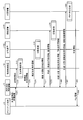
- FIG. 21 is a sequence diagram illustrating a processing procedure of the determination process by the determination system 401 shown in FIG.
- Steps S71 to S74 shown in FIG. 20 are the same processes as steps S1 to S4 shown in FIG.
- the inside / outside determination control device 3 transmits the reduced polygon information D11 to the dividing device 310 (step S75), and causes the preprocessing to be executed.
- the dividing device 310 executes a dividing process for dividing the polygon after the vertex reduction into a plurality of polygons (step S76), and determines the inside / outside determination control device for the polygon information D13'after the vertex reduction / division. It is transmitted to 3 (step S77).
- Step S76 is the same process as step S53 shown in FIG.
- the inside / outside determination control device 3 transmits the polygon information D13'and the coordinate information D20 after the vertex reduction / division to the rotating device 210 (step S78), and causes the preprocessing to be executed.
- the rotating device 210 rotates each polygon for internal / external determination and the coordinates of the determination target based on the vertex reduction / division polygon information D13'and the coordinate information D20 received from the internal / external determination control device 3.
- the rotation process is executed (step S79), and the vertex reduction / division / post-rotation polygon information D12'and the post-rotation coordinate information D22 are transmitted to the inside / outside determination control device 3 (step S80).
- Step S79 is the same process as step S33 shown in FIG.
- the inside / outside determination control device 3 transmits the vertex reduction / division / post-rotation polygon information D12'and the post-rotation coordinate information D22 to the determination device 20 (step S81), and executes the inside / outside determination process.
- the determination device 20 determines the coordinates of the determination target for each polygon for internal / external determination after division and rotation based on the polygon information D12'after reduction / division / rotation and the coordinate information D22 after rotation.
- Performs an inside / outside determination process for determining whether or not the polygon exists inside or outside the polygon step S82).
- the inside / outside determination process is the same process as step S6 shown in FIG. Further, steps S83 and S84 shown in FIG. 21 are the same processes as steps S7 and S8 shown in FIG.
- the vertex reduction processing for the polygon for internal / external determination, the rotation processing for the polygon for internal / external determination after vertex reduction, and the polygon for internal / external determination after vertex reduction and rotation are performed.
- the division process is sequentially executed as a preprocess.
- the vertex reduction process for the polygon for internal / external determination the rotation process for the polygon for internal / external determination after vertex reduction, and the division process for the polygon for internal / external determination after vertex reduction and rotation are performed.
- the preprocessing is performed in the order of is described as an example, the order of the preprocessing is not limited.
- FIG. 22 is a sequence diagram for explaining the processing procedure of the determination process in the first modification of the fourth embodiment. Steps S91 to S94 shown in FIG. 22 are the same processes as steps S1 to S4 shown in FIG. 7.
- the inside / outside determination control device 3 transmits the reduced polygon information D11 and the coordinate information D20 to the rotating device 210 (step S95), and causes the preprocessing to be executed.
- the rotating device 210 rotates the polygon for determining the inside / outside after reducing the vertices and the coordinates of the determination target based on the reduced polygon information D11 and the coordinate information D20 received from the inside / outside determination control device 3.
- the rotation process is executed (step S96), and the vertex reduction / post-rotation polygon information D12 ′′ and the post-rotation coordinate information D22 are transmitted to the inside / outside determination control device 3 (step S97). This is the same process as S33.
- the inside / outside determination control device 3 transmits the post-rotation polygon information D12 ′′ and the post-rotation coordinate information D22 to the determination device 20 (step S98), and causes the inside / outside determination process to be executed. Based on the post-rotation polygon information D12 ′′ and the post-rotation coordinate information D22, whether the coordinates to be determined exist inside or outside the polygon for internal / external determination for each polygon for vertex reduction and internal / external determination after rotation.
- the inside / outside determination process for determining the above is performed (step S99).
- the inside / outside determination process is the same process as step S6 shown in FIG. Further, steps S100 and S101 shown in FIG. 21 are the same processes as steps S7 and S8 shown in FIG.
- the pretreatment device may be two, the vertex reduction device 10 and the division device 310.
- the processing procedure of the determination process in this case will be described.
- FIG. 23 is a sequence diagram for explaining the processing procedure of the determination process in the second modification of the fourth embodiment.
- Steps S111 to S114 shown in FIG. 23 are the same processes as steps S1 to S4 shown in FIG. 7.
- Steps S115 to S117 shown in FIG. 23 are the same processes as steps S75 to S77 shown in FIG.
- the inside / outside determination control device 3 transmits the polygon information D13'and the coordinate information D20 after vertex reduction / division to the determination device 20 (step S118), and causes the inside / outside determination process to be executed.
- the determination device 20 is based on the polygon information D13'after vertex reduction / division and the coordinate information D20, and the coordinates of the determination target are polygons for internal / external determination for each polygon for internal / external determination after vertex reduction and division.
- Performs an inside / outside determination process for determining whether or not it exists inside or outside step S119).
- the inside / outside determination process is the same process as step S6 shown in FIG.
- steps S120 and S121 shown in FIG. 23 are the same processes as steps S7 and S8 shown in FIG.
- the pretreatment device may be two, a rotating device 210 and a dividing device 310.
- the processing procedure of the determination process in this case will be described.
- FIG. 24 is a sequence diagram for explaining the processing procedure of the determination process in the third modification of the fourth embodiment. Steps S131 to S134 shown in FIG. 24 are the same processes as steps S51 to S54 shown in FIG.
- the inside / outside determination control device 3 transmits the polygon information D13 and the coordinate information D20 after division to the rotating device 210 (step S135), and causes the preprocessing to be executed.
- the rotating device 210 performs a rotation process for rotating each polygon for internal / external determination and the coordinates to be determined based on the divided polygon information D13 and the coordinate information D20 received from the internal / external determination control device 3. It is executed (step S136), and the polygon information D13 "after division / rotation and the coordinate information D22 after rotation are transmitted to the inside / outside determination control device 3 (step S137).
- Step S136 is the same process as step S33 shown in FIG. is there.
- the inside / outside determination control device 3 transmits the polygon information D13 ′′ after division / rotation and the coordinate information D22 after rotation to the determination device 20 (step S138), and causes the inside / outside determination process to be executed. Based on the polygon information D13 "and the post-rotation coordinate information D22, it is determined whether or not the coordinates to be determined exist inside or outside the polygon for internal / external determination for each polygon for internal / external determination after division and rotation.
- the inside / outside determination process is performed (step S139).
- the inside / outside determination process is the same process as step S6 shown in FIG. Further, steps S140 and S141 shown in FIG. 24 are the same processes as steps S7 and S8 shown in FIG.
- FIG. 25 is a diagram illustrating an experimental model.
- one polygon as shown in FIG. 25 and 4000 vehicles are targeted.
- the polygon shown in FIG. 25 is a road polygon having a long side of 7000 m, a short side of 35 m, and an interval between vertices of 1 m.
- the vehicle provides three patterns of outside the MBR and outside the polygon, inside the MBR and outside the polygon, and inside the MBR and inside the polygon, and makes a comparison by adopting the average value of the determination results of 10 trials.
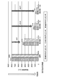
- FIG. 26 is a diagram for explaining the PIP processing time in the case where the inside / outside determination is performed after the vertex reduction processing is performed and the case where the inside / outside determination is performed without executing the preprocessing.
- the number of vertices was reduced to 1/2, 1/10, and 1/100 as compared with the case where the inside / outside judgment was performed without executing the preprocessing (“reference” in FIG. 26).
- the processing time could be shortened to 0.5 times, 0.15 times, and 0.07 times the standard PIP time, respectively.
- FIG. 27 is a diagram illustrating the division process performed in the verification.
- the road polygon P14 (see (1) in FIG. 27) is divided into two equal parts into road polygons P14-1 and P-14-2 (see (2) in FIG. 27), and MBR44 (see FIG. 27 (2)).
- 27 (see (1))) divided into MBR44-1, 44-2 (see (2) in FIG. 27), which has a smaller area than MBR44, and the PIP processing time without executing preprocessing.
- the PIP processing time when the inside / outside judgment was performed was measured.
- FIG. 28 is a diagram for explaining the PIP processing time in the case where the inside / outside determination is performed after the division processing is performed and the case where the inside / outside determination is performed without executing the preprocessing.
- the experimental result is a model assuming that all 4000 vehicles are in a position to move out of the MBR by the division process. In this way, the model is extreme because it is used as the basis for the estimated value of how much the improvement effect of the method can be expected.
- the total time required for 4000 vehicles in the MBR to be PIP processed was 7984 ms (“No division” in FIG. 28).
- the division process is executed and the inside / outside determination is performed, all 4000 vehicles in the MBR are "outside the MBR", so the process is completed only by the simple determination. In other words, by the division process, the cross product calculation for the vehicle outside the MBR can be omitted. Therefore, when the division process was executed and the inside / outside determination was performed (“with division” in FIG. 28), the total time required for the inside / outside determination process for 4000 units outside the MBR was 1.4 ms.
- the total processing time which is the sum of the division processing time and the PIP processing time, is shortened to 0.00018 times the processing time when the preprocessing is not executed. I was able to do it.
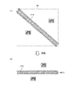
- FIG. 29 is a diagram illustrating the rotation process performed in the verification.
- the PIP processing time when the road polygon P14 (see (1) in FIG. 29) and the vehicle are rotated by 45 ° (see (2) in FIG. 29) is used.
- the PIP processing time when the inside / outside judgment was performed without executing the preprocessing was measured.
- the MBR becomes the MBR44-3 having a smaller area than the MBR44 according to the road polygon P15 rotated by 45 °.
- the experimental results are based on the assumption that all 4000 vehicles are in a position to move out of the MBR by rotation processing. In this way, the model is extreme because it is used as the basis for the estimated value of how much the improvement effect of the method can be expected.
- the rotation processing time was as short as 1/10000 or less of the PIP processing time.
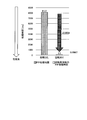
- FIG. 30 is a diagram for explaining the PIP processing time in the case where the inside / outside determination is performed after the rotation processing is performed and the case where the inside / outside determination is performed without executing the preprocessing.
- the total time required for the 4000 vehicles in the MBR to be PIP-processed was 8127 ms (“no rotation” in FIG. 30).
- the total processing time which is the sum of the rotation processing time and the PIP processing time, is shortened to 0.0004 times the processing time when the preprocessing is not executed. I was able to do it.
- FIG. 31 is a diagram illustrating another application example of the determination system according to the first to fourth embodiments.
- the determination system according to the first to fourth embodiments can be applied to the coordinate determination (region: sea route) of the ship on the sea route.
- the width of the sea route is widened to Wm (W can be freely set).
- the determination system according to the first to fourth embodiments replaces the road with a new sea route, replaces the automobile with a ship, and determines the position of the ship at sea.
- the determination system according to the first to fourth embodiments can be applied to tracking fish (area: river) with a coordinate sensor. Specifically, the determination system according to the first to fourth embodiments replaces a road with a river, replaces an automobile with a fish, and determines the position of a fish on the river.
- each component of the vertex reduction device 10 shown in FIG. 2, the determination device 20 shown in FIG. 4, the rotating device 210 shown in FIG. 11, and the dividing device 310 shown in FIG. 16 is functionally conceptual and is not necessarily physically illustrated. It does not need to be configured as. That is, the specific form of the distribution and integration of the functions of the vertex reduction device 10, the determination device 20, the rotating device 210, and the dividing device 310 is not limited to the one shown in the drawing, and all or a part thereof may be used in various loads or usage conditions. Depending on the unit, it can be functionally or physically distributed or integrated.
- each process performed by the vertex reduction device 10, the determination device 20, the rotation device 210, and the division device 310 may be realized by a CPU and a program in which an arbitrary part is analyzed and executed by the CPU. Further, each process performed by the vertex reduction device 10 may be realized as hardware by wired logic.
- FIG. 32 is a diagram showing an example of a computer in which the vertex reduction device 10, the determination device 20, the rotation device 210, and the division device 310 are realized by executing the program.
- the computer 1000 has, for example, a memory 1010 and a CPU 1020.
- the computer 1000 also has a hard disk drive interface 1030, a disk drive interface 1040, a serial port interface 1050, a video adapter 1060, and a network interface 1070. Each of these parts is connected by a bus 1080.
- Memory 1010 includes ROM 1011 and RAM 1012.
- the ROM 1011 stores, for example, a boot program such as a BIOS (Basic Input Output System).
- BIOS Basic Input Output System
- the hard disk drive interface 1030 is connected to the hard disk drive 1090.
- the disk drive interface 1040 is connected to the disk drive 1100.
- a removable storage medium such as a magnetic disk or an optical disk is inserted into the disk drive 1100.
- the serial port interface 1050 is connected to, for example, a mouse 1110 and a keyboard 1120.
- the video adapter 1060 is connected to, for example, the display 1130.
- the hard disk drive 1090 stores, for example, an OS (Operating System) 1091, an application program 1092, a program module 1093, and program data 1094. That is, the program that defines each process of the vertex reduction device 10, the determination device 20, the rotating device 210, and the dividing device 310 is implemented as a program module 1093 in which a code that can be executed by the computer 1000 is described.
- the program module 1093 is stored in, for example, the hard disk drive 1090.
- the program module 1093 for executing the same processing as the functional configuration in the vertex reduction device 10, the determination device 20, the rotating device 210, and the dividing device 310 is stored in the hard disk drive 1090.
- the hard disk drive 1090 may be replaced by an SSD (Solid State Drive).
- the setting data used in the processing of the above-described embodiment is stored as program data 1094 in, for example, a memory 1010 or a hard disk drive 1090. Then, the CPU 1020 reads the program module 1093 and the program data 1094 stored in the memory 1010 and the hard disk drive 1090 into the RAM 1012 as needed, and executes the program.
- the program module 1093 and the program data 1094 are not limited to those stored in the hard disk drive 1090, but may be stored in, for example, a removable storage medium and read by the CPU 1020 via the disk drive 1100 or the like. Alternatively, the program module 1093 and the program data 1094 may be stored in another computer connected via a network (LAN (Local Area Network), WAN (Wide Area Network), etc.). Then, the program module 1093 and the program data 1094 may be read by the CPU 1020 from another computer via the network interface 1070.
- LAN Local Area Network
- WAN Wide Area Network
- Judgment system 2 Client terminal 3 Inside / outside judgment control device 10 Vertex reduction device 11,1,2,111,311 Communication unit 12,22,212,312 Storage unit 13,23,213,313 Control unit 20 Judgment Device 131 Vertex reduction part 231 Inside / outside judgment part 210 Rotating device 310 Splitting device 2131 Rotating part 3131 Dividing part
Landscapes
- Engineering & Computer Science (AREA)
- Physics & Mathematics (AREA)
- Software Systems (AREA)
- Theoretical Computer Science (AREA)
- Computer Graphics (AREA)
- General Physics & Mathematics (AREA)
- Geometry (AREA)
- Computer Hardware Design (AREA)
- Architecture (AREA)
- General Engineering & Computer Science (AREA)
- Remote Sensing (AREA)
- Image Generation (AREA)
- Processing Or Creating Images (AREA)
Abstract
Description
まず、実施の形態1について説明する。本実施の形態1では、判定対象である座標が内外判定用の多角形の内外に存在するかを判定する内外判定処理の前に、内外判定用の多角形の頂点を削減することによって、内外判定処理に要する処理時間を短縮する。
図1は、実施の形態1に係る判定システムの構成の一例を示すブロック図である。図1に示すように、本実施の形態1に係る判定システム1は、クライアント端末2、内外判定制御装置3、頂点削減装置10及び判定装置20を有する。クライアント端末2、内外判定制御装置3は、ネットワーク等を介して接続する。内外判定制御装置3、頂点削減装置10及び判定装置20は、ネットワーク等を介して接続する。
次に、図1に示す頂点削減装置10について説明する。図2は、図1に示す頂点削減装置10の構成の一例を示すブロック図である。図2に示すように、頂点削減装置10は、通信部11、記憶部12及び制御部13を有する。
参考文献1:“Ramer-Douglas-Peucker Algorithm”,[online],[令和1年8月23日検索],インターネット<URL:https://siguniang.wordpress.com/2012/07/16/ramer-douglas-peucker-algorithm/>
次に、図1に示す判定装置20について説明する。図4は、図1に示す判定装置20の構成の一例を示すブロック図である。図4に示すように、判定装置20は、通信部21、記憶部22及び制御部23を有する。
次に、頂点削減装置10が実行する頂点削減処理について具体的に説明する。図6は、頂点削減処理を説明する図である。図6の(1)は、頂点削減処理前の内外判定用の多角形P10を示し、図6の(2)は、頂点削減処理後の多角形P11を示す。説明のために、図6は、MBR40、判定対象である座標C1,C2,C3も示す。
次に、判定システム1における判定処理の処理手順について説明する。図7は、図1に示す判定システム1による判定処理の処理手順を説明するシーケンス図である。
次に、頂点削減処理(ステップS3)の処理手順について説明する。図8は、図7に示す頂点削減処理の処理手順を示すフローチャートである。
次に、内外判定処理(ステップS6)の処理手順について説明する。図9は、図7に示す内外判定処理の処理手順を示すフローチャートである。
このように、実施の形態1では、内外判定用の多角形の頂点を削減する前処理を行い、頂点が削減された多角形を用いて各座標に対する多角形内外判定処理を行う。したがって、実施の形態1では、詳細判定処理時に、頂点が削減された多角形を基に詳細判定が実行されるため、当初の内外判定用の多角形を対象として詳細判定を行う場合と比較して、詳細判定処理の処理時間を短縮することができる。
次に、実施の形態2について説明する。実施の形態2では、判定装置による内外判定処理の前に、内外判定用の多角形及び判定対象の座標を回転し、回転後の多角形を含むMBRの領域を削減することによって、内外判定処理に要する処理時間を短縮する。
次に、図10に示す回転装置210について説明する。図11は、図10に示す回転装置210の構成の一例を示すブロック図である。図11に示すように、回転装置210は、通信部211(出力部、第1の出力部)、記憶部212及び制御部213を有する。
参考文献2:“Minimum-Area Rectangle Containing a Set of Points”,[online],[令和1年8月23日検索],インターネット<URL:https://www.geometrictools.com/Documentation/MinimumAreaRectangle.pdf>
次に、回転装置210が実行する回転処理について具体的に説明する。図12は、回転処理を説明する図である。図12の(1)は、回転処理前の内外判定用の多角形P10及び判定対象の座標C1,C2,C3を示し、図12の(2)は、回転処理後の多角形P11及び回転後の座標C12,C22,C32を示す。また、説明のために、図12は、回転処理前のMBR40と、回転処理後に設定されるMBR42も示す。
次に、判定システム201における判定処理の処理手順について説明する。図13は、図10に示す判定システム201による判定処理の処理手順を説明するシーケンス図である。
次に、回転処理(ステップS33)の処理手順について説明する。図14は、図13に示す回転処理の処理手順を示すフローチャートである。
このように、実施の形態2では、内外判定用の多角形及び判定対象の座標を回転する前処理を行い、回転前と比して領域が削減されたMBRを用いて、回転後の判定対象の各座標に対する多角形内外判定処理を行う。したがって、実施の形態2では、領域が削減されたMBRを用いて簡易判定を行うため、簡易判定のみで内外判定用の多角形外であると判定される座標が増える。これによって、実施の形態2では、詳細判定の実行回数を減らすことができ、判定処理の処理時間全体を短縮することができる。
次に、実施の形態3について説明する。実施の形態3では、判定装置による内外判定処理の前に、内外判定用の多角形を、領域の小さな複数の多角形に分割し、分割後の多角形に対する各MBRの領域を削減することによって、内外判定処理に要する処理時間を短縮する。
次に、図15に示す分割装置310について説明する。図16は、図15に示す分割装置310の構成の一例を示すブロック図である。図16に示すように、分割装置310は、通信部311(第2の出力部)、記憶部312及び制御部313を有する。
参考文献3:“Polygon triangulation inO(n log logn) time with simple data structures”,[online],[令和1年8月23日検索],インターネット<URL:https://link.springer.com/article/10.1007%2FBF02187846>
次に、分割装置310が実行する分割処理について具体的に説明する。図17は、分割処理を説明する図である。図17の(1)は、分割処理前の内外判定用の多角形P10及び判定対象の座標C1,C2,C3を示し、図17の(2)は、分割処理後の多角形P13-1,P13-2,P13-3を示す。また、説明のために、図17は、MBR40と、分割後の各多角形P13-1,P13-2,P13-3をそれぞれに対応するMBR43-1,43-2,43-3と、判定対象である座標C1,C2,C3も示す。
次に、判定システム301における判定処理の処理手順について説明する。図18は、図15に示す判定システム301による判定処理の処理手順を説明するシーケンス図である。
次に、分割処理(ステップS53)の処理手順について説明する。図19は、図18に示す分割処理の処理手順を示すフローチャートである。
このように、実施の形態3では、内外判定用の多角形を複数の多角形に分割する前処理を行い、分割前の多角形に対するMBRと比して、全体として領域が削減された複数のMBRを用いて、判定対象の各座標に対する多角形内外判定処理を行う。したがって、実施の形態3では、全体として領域が削減された複数のMBRを用いて簡易判定を行うため、簡易判定のみで内外判定用の多角形外であると判定される座標が増える。これによって、実施の形態3では、詳細判定の実行回数を減らすことができ、判定処理の処理時間全体を短縮することができる。
次に、実施の形態4について説明する。実施の形態4では、実施の形態1~3で説明した前処理を順に実行することによって、内外判定処理に要する処理時間をさらに短縮する。
次に、判定システム401における判定処理の処理手順について説明する。図21は、図20に示す判定システム401による判定処理の処理手順を説明するシーケンス図である。
このように、実施の形態4では、内外判定用の多角形に対する頂点削減処理、頂点削減後の内外判定用の多角形に対する回転処理、及び、頂点削減及び回転後の内外判定用の多角形に対する分割処理を、前処理として順次実行する。これによって、実施の形態4では、簡易判定のみで内外判定用の多角形外であると判定される座標が増えることが期待でき、実施の形態1~3と比して、内外判定処理に要する処理時間をさらに短縮することができる。
また、実施の形態4として、前処理装置として、頂点削減装置10、分割装置310及び回転装置210を有する例を説明したがこれに限らない。前処理装置は、頂点削減装置10及び回転装置210の2つであってもよい。この場合の判定処理の処理手順について説明する。
また、前処理装置は、頂点削減装置10及び分割装置310の2つであってもよい。この場合の判定処理の処理手順について説明する。
また、前処理装置は、回転装置210及び分割装置310の2つであってもよい。この場合の判定処理の処理手順について説明する。
本実施の形態1~3における判定システムを用いた判定方法の、従来の判定方法に対する性能比較を検証した。図25は、実験モデルを説明する図である。本検証では、図25に示すような1つの多角形と車両4000台とを対象とする。図25に示す多角形は、具体的には、長辺が7000m、であり、短辺が35mであり、頂点間の間隔が1mである道路ポリゴンである。そして、本検証は、車両が、MBR外かつポリゴン外、MBR内かつポリゴン外、MBR内かつポリゴン内の3つパターンを設け、10回試行した判定結果の平均値を採用して比較を行う。
図31は、実施の形態1~4に係る判定システムの他の適用例を説明する図である。実施の形態1~4に係る判定システムは、海路上の船の座標判定(領域:海路)に適用が可能である。まず、海路(図31の(1)に示す実線)を基に、海路の幅をWm(Wは自由に設定できる。)まで広げる。そして、実施の形態1~4に係る判定システムは、道路を新たな海路に置き換え、自動車を船に置き換えて、海上の船の位置判定を行う。
図2に示す頂点削減装置10、図4に示す判定装置20、図11に示す回転装置210、図16に示す分割装置310の各構成要素は機能概念的なものであり、必ずしも物理的に図示のように構成されていることを要しない。すなわち、頂点削減装置10、判定装置20、回転装置210及び分割装置310の機能の分散および統合の具体的形態は図示のものに限られず、その全部または一部を、各種の負荷や使用状況などに応じて、任意の単位で機能的または物理的に分散または統合して構成することができる。
図32は、プログラムが実行されることにより、頂点削減装置10、判定装置20、回転装置210及び分割装置310が実現されるコンピュータの一例を示す図である。コンピュータ1000は、例えば、メモリ1010、CPU1020を有する。また、コンピュータ1000は、ハードディスクドライブインタフェース1030、ディスクドライブインタフェース1040、シリアルポートインタフェース1050、ビデオアダプタ1060、ネットワークインタフェース1070を有する。これらの各部は、バス1080によって接続される。
2 クライアント端末
3 内外判定制御装置
10 頂点削減装置
11,21,211,311 通信部
12,22,212,312 記憶部
13,23,213,313 制御部
20 判定装置
131 頂点削減部
231 内外判定部
210 回転装置
310 分割装置
2131 回転部
3131 分割部
Claims (5)
- 判定対象である座標が内外判定用の多角形の内外に存在するかを判定する判定処理の前処理として、前記内外判定用の多角形の各頂点の座標情報と、前記内外判定用の多角形の各頂点の座標情報とを取得し、前記判定対象である座標と前記内外判定用の多角形とを回転する回転部と、
回転後の前記内外判定用の多角形の各頂点の座標情報と、回転後の判定対象である座標とを回転後座標情報として出力する出力部と、
を有することを特徴とする前処理装置。 - 判定対象である座標が内外判定用の多角形の内外に存在するか否かを判定する判定処理を行う判定装置と、前記判定処理の前処理を行う第1の前処理装置と、を有する判定システムにおいて、
前記第1の前処理装置は、
前処理として、前記内外判定用の多角形の各頂点の座標情報と、前記内外判定用の多角形の各頂点の座標情報とを取得し、前記判定対象である座標と前記内外判定用の多角形とを回転する回転部と、
回転後の前記内外判定用の多角形の各頂点の座標情報と、回転後の判定対象である座標とを回転後座標情報として出力する第1の出力部と、
を有し、
前記判定装置は、
前記前処理後の情報を用いて、前記判定対象である座標が前記内外判定用の多角形の内外に存在するか否かを判定する
ことを特徴とする判定システム。 - 前記判定処理の前処理を行う第2の前処理装置をさらに有し、
前記第2の前処理装置は、
前処理として、前記内外判定用の多角形の各頂点の座標情報を取得し、前記内外判定用の多角形を複数の多角形に分割する分割部と、
分割した内外判定用の各多角形の各頂点の座標情報を、分割後多角形情報として出力する第2の出力部と、
を有することを特徴とする請求項2に記載の判定システム。 - 前処理装置が行う前処理方法であって、
判定対象である座標が内外判定用の多角形の内外に存在するかを判定する判定処理の前処理として、前記内外判定用の多角形の各頂点の座標情報と、前記内外判定用の多角形の各頂点の座標情報とを取得し、前記判定対象である座標と前記内外判定用の多角形とを回転する工程と、
回転後の前記内外判定用の多角形の各頂点の座標情報と、回転後の判定対象である座標とを回転後座標情報として出力する工程と、
を含んだことを特徴とする前処理方法。 - 判定対象である座標が内外判定用の多角形の内外に存在するかを判定する判定処理の前処理として、前記内外判定用の多角形の各頂点の座標情報と、前記内外判定用の多角形の各頂点の座標情報とを取得し、前記判定対象である座標と前記内外判定用の多角形とを回転するステップと、
回転後の前記内外判定用の多角形の各頂点の座標情報と、回転後の判定対象である座標とを回転後座標情報として出力するステップと、
をコンピュータに実行させるための前処理プログラム。
Priority Applications (5)
| Application Number | Priority Date | Filing Date | Title |
|---|---|---|---|
| US17/640,354 US11954812B2 (en) | 2019-09-12 | 2019-09-12 | Preprocessing device, determination system, preprocessing method, and preprocessing program |
| JP2021545063A JP7168099B2 (ja) | 2019-09-12 | 2019-09-12 | 前処理装置、判定システム、前処理方法および前処理プログラム |
| PCT/JP2019/035988 WO2021048992A1 (ja) | 2019-09-12 | 2019-09-12 | 前処理装置、判定システム、前処理方法および前処理プログラム |
| CN201980100208.1A CN114424248B (zh) | 2019-09-12 | 2019-09-12 | 预处理装置、判定系统、预处理方法以及记录介质 |
| EP19944858.0A EP4009280B1 (en) | 2019-09-12 | 2019-09-12 | Preprocessing device, determining system, preprocessing method, and preprocessing program |
Applications Claiming Priority (1)
| Application Number | Priority Date | Filing Date | Title |
|---|---|---|---|
| PCT/JP2019/035988 WO2021048992A1 (ja) | 2019-09-12 | 2019-09-12 | 前処理装置、判定システム、前処理方法および前処理プログラム |
Publications (1)
| Publication Number | Publication Date |
|---|---|
| WO2021048992A1 true WO2021048992A1 (ja) | 2021-03-18 |
Family
ID=74866320
Family Applications (1)
| Application Number | Title | Priority Date | Filing Date |
|---|---|---|---|
| PCT/JP2019/035988 Ceased WO2021048992A1 (ja) | 2019-09-12 | 2019-09-12 | 前処理装置、判定システム、前処理方法および前処理プログラム |
Country Status (5)
| Country | Link |
|---|---|
| US (1) | US11954812B2 (ja) |
| EP (1) | EP4009280B1 (ja) |
| JP (1) | JP7168099B2 (ja) |
| CN (1) | CN114424248B (ja) |
| WO (1) | WO2021048992A1 (ja) |
Cited By (1)
| Publication number | Priority date | Publication date | Assignee | Title |
|---|---|---|---|---|
| US12602481B1 (en) | 2025-04-19 | 2026-04-14 | The Crown And The Cross Llc | Neural override verification and constraint architecture for sovereign AGI execution |
Families Citing this family (2)
| Publication number | Priority date | Publication date | Assignee | Title |
|---|---|---|---|---|
| US12281901B2 (en) * | 2019-09-12 | 2025-04-22 | Nippon Telegraph And Telephone Corporation | Preprocessing device, determination system, preprocessing method, and preprocessing program |
| JP7355216B2 (ja) * | 2020-03-05 | 2023-10-03 | 日本電信電話株式会社 | 管理装置、管理方法及び管理プログラム |
Citations (3)
| Publication number | Priority date | Publication date | Assignee | Title |
|---|---|---|---|---|
| JPH07182532A (ja) * | 1993-12-22 | 1995-07-21 | Sega Enterp Ltd | 領域内外判定方法 |
| JP2000251081A (ja) * | 1999-02-26 | 2000-09-14 | Canon Inc | 内点判定方法、グラフィック描画装置およびプログラム記憶媒体 |
| JP2003085577A (ja) * | 2001-09-10 | 2003-03-20 | Canon Inc | 内外点判定アルゴリズム |
Family Cites Families (12)
| Publication number | Priority date | Publication date | Assignee | Title |
|---|---|---|---|---|
| JPS63118982A (ja) | 1986-11-07 | 1988-05-23 | Fujio Yamaguchi | 多角形に対する点の内外判定演算処理方法 |
| JPH1055166A (ja) * | 1996-08-09 | 1998-02-24 | Mitsubishi Electric Corp | 多角形塗りつぶしアクセラレータ |
| US6320580B1 (en) * | 1997-11-07 | 2001-11-20 | Sega Enterprises, Ltd. | Image processing apparatus |
| JP3829014B2 (ja) * | 1998-06-03 | 2006-10-04 | 株式会社コナミデジタルエンタテインメント | ビデオゲーム装置 |
| CN100377170C (zh) * | 2006-08-22 | 2008-03-26 | 北京方正奥德计算机系统有限公司 | 一种图像线性几何变形自动矫正的方法 |
| JP4995827B2 (ja) * | 2006-09-13 | 2012-08-08 | パナソニック株式会社 | 画像処理装置、画像処理用集積回路、画像処理システム、インプットアセンブラ装置、インプットアセンブル用集積回路 |
| US8374391B1 (en) * | 2010-04-16 | 2013-02-12 | The Boeing Company | Model of visibility of targets |
| US8930245B2 (en) * | 2010-06-23 | 2015-01-06 | Justin Streich | Methods, systems and machines for identifying geospatial compatibility between consumers and providers of goods or services |
| DE102012103011A1 (de) * | 2012-04-05 | 2013-10-10 | Krauss-Maffei Wegmann Gmbh & Co. Kg | Verfahren zur synchronen Wiedergabe einer virtuellen Realität in einer verteilten Simulationsvorrichtung |
| CN103793145B (zh) * | 2014-02-21 | 2016-09-07 | 湖南省交通规划勘察设计院 | 一种基于AutoCAD的图框参数识别与图纸输出方法 |
| CN105204629B (zh) * | 2015-09-02 | 2018-11-13 | 成都上生活网络科技有限公司 | 一种3d手势识别方法 |
| US11543800B2 (en) * | 2017-07-13 | 2023-01-03 | Stratasys Ltd. | Method of printing a 3D model from point cloud data |
-
2019
- 2019-09-12 EP EP19944858.0A patent/EP4009280B1/en active Active
- 2019-09-12 US US17/640,354 patent/US11954812B2/en active Active
- 2019-09-12 CN CN201980100208.1A patent/CN114424248B/zh active Active
- 2019-09-12 JP JP2021545063A patent/JP7168099B2/ja active Active
- 2019-09-12 WO PCT/JP2019/035988 patent/WO2021048992A1/ja not_active Ceased
Patent Citations (3)
| Publication number | Priority date | Publication date | Assignee | Title |
|---|---|---|---|---|
| JPH07182532A (ja) * | 1993-12-22 | 1995-07-21 | Sega Enterp Ltd | 領域内外判定方法 |
| JP2000251081A (ja) * | 1999-02-26 | 2000-09-14 | Canon Inc | 内点判定方法、グラフィック描画装置およびプログラム記憶媒体 |
| JP2003085577A (ja) * | 2001-09-10 | 2003-03-20 | Canon Inc | 内外点判定アルゴリズム |
Non-Patent Citations (6)
| Title |
|---|
| BOUNDING CONTAINERS FOR POINT SETS, 23 August 2019 (2019-08-23), Retrieved from the Internet <URL:http://geomalgorithms.com/a08-_containers.html> |
| INCLUSION OF A POINT IN A POLYGON, 23 August 2019 (2019-08-23), Retrieved from the Internet <URL:http://geomalgorithms.com/a03-inclusion.html> |
| MINIMUM-AREA RECTANGLE CONTAINING A SET OF POINTS, 23 August 2019 (2019-08-23), Retrieved from the Internet <URL:https://www.geometrictools.com/Documentation/MinimumAreaRectangle> |
| POLYGON TRIANGULATION INO(N LOG LOGN) TIME WITH SIMPLE DATA STRUCTURES, 23 August 2019 (2019-08-23), Retrieved from the Internet <URL:https://link.springer.com/article/10.1007%2FBF02187846> |
| RAMER-DOUGLAS-PEUCKER ALGORITHM, 23 August 2019 (2019-08-23), Retrieved from the Internet <URL:https://siguniang.wordpress.com/2012/07/16/ramer-douglas-peucker-algorithm/> |
| See also references of EP4009280A4 |
Cited By (1)
| Publication number | Priority date | Publication date | Assignee | Title |
|---|---|---|---|---|
| US12602481B1 (en) | 2025-04-19 | 2026-04-14 | The Crown And The Cross Llc | Neural override verification and constraint architecture for sovereign AGI execution |
Also Published As
| Publication number | Publication date |
|---|---|
| US20220327791A1 (en) | 2022-10-13 |
| EP4009280A4 (en) | 2023-05-03 |
| US11954812B2 (en) | 2024-04-09 |
| EP4009280A1 (en) | 2022-06-08 |
| JPWO2021048992A1 (ja) | 2021-03-18 |
| CN114424248B (zh) | 2025-07-15 |
| EP4009280B1 (en) | 2024-09-04 |
| JP7168099B2 (ja) | 2022-11-09 |
| CN114424248A (zh) | 2022-04-29 |
Similar Documents
| Publication | Publication Date | Title |
|---|---|---|
| CN113095336B (zh) | 关键点检测模型的训练方法和检测目标对象关键点的方法 | |
| US10510154B2 (en) | Adaptive processing of spatial imaging data | |
| JP7168099B2 (ja) | 前処理装置、判定システム、前処理方法および前処理プログラム | |
| US12511932B2 (en) | Authentication system using object fingerprinting | |
| US20130094397A1 (en) | Method and apparatus for localized and scalable packet forwarding | |
| US11599817B2 (en) | Logical qubit encoding surface | |
| CN114170257A (zh) | 一种拟合弯曲目标轮廓的、装置、计算机设备及存储介质 | |
| WO2021048987A1 (ja) | 前処理装置、判定システム、前処理方法および前処理プログラム | |
| CN113689270A (zh) | 黑产设备的确定方法、电子设备、存储介质及程序产品 | |
| CN111105435A (zh) | 标志物匹配方法、装置及终端设备 | |
| CN109073398B (zh) | 一种建立地图的方法、定位方法、装置、终端及存储介质 | |
| CN110544159B (zh) | 一种地图信息处理方法、装置、可读存储介质和电子设备 | |
| WO2021048993A1 (ja) | 前処理装置、判定システム、前処理方法および前処理プログラム | |
| US9916663B2 (en) | Image processing method and process simulation apparatus | |
| JP7239053B2 (ja) | 生成装置、生成方法及び生成プログラム | |
| CN114913305B (zh) | 模型处理方法、装置、设备、存储介质及计算机程序产品 | |
| CN115166754A (zh) | 一种激光雷达点云的处理方法、装置、电子设备及介质 | |
| JP7067627B2 (ja) | 検知装置、判定方法、及びプログラム | |
| CN117876410A (zh) | 点云数据分割方法、装置、电子设备及可读存储介质 | |
| CN113886386B (zh) | 一种GeoHash确定方法、装置、设备及介质 | |
| CN118114076A (zh) | 一种点云聚类的方法、装置、设备及存储介质 | |
| CN118631509A (zh) | 跨资源池的api行为检测方法及装置 | |
| CN115957517A (zh) | 游戏对象刷新方法、装置、电子设备及可读存储介质 | |
| CN114926533A (zh) | 目标对象定位的地图表示方法、装置和计算机设备 | |
| CN117268383A (zh) | 全局定位方法、装置、计算机设备和存储介质 |
Legal Events
| Date | Code | Title | Description |
|---|---|---|---|
| 121 | Ep: the epo has been informed by wipo that ep was designated in this application |
Ref document number: 19944858 Country of ref document: EP Kind code of ref document: A1 |
|
| ENP | Entry into the national phase |
Ref document number: 2021545063 Country of ref document: JP Kind code of ref document: A |
|
| ENP | Entry into the national phase |
Ref document number: 2019944858 Country of ref document: EP Effective date: 20220303 |
|
| NENP | Non-entry into the national phase |
Ref country code: DE |
|
| WWG | Wipo information: grant in national office |
Ref document number: 201980100208.1 Country of ref document: CN |