WO2021053855A1 - シミュレーション装置、シミュレーションプログラムおよびシミュレーション方法 - Google Patents
シミュレーション装置、シミュレーションプログラムおよびシミュレーション方法 Download PDFInfo
- Publication number
- WO2021053855A1 WO2021053855A1 PCT/JP2020/009130 JP2020009130W WO2021053855A1 WO 2021053855 A1 WO2021053855 A1 WO 2021053855A1 JP 2020009130 W JP2020009130 W JP 2020009130W WO 2021053855 A1 WO2021053855 A1 WO 2021053855A1
- Authority
- WO
- WIPO (PCT)
- Prior art keywords
- behavior
- simulation
- robot
- virtual space
- target
- Prior art date
- Legal status (The legal status is an assumption and is not a legal conclusion. Google has not performed a legal analysis and makes no representation as to the accuracy of the status listed.)
- Ceased
Links
Images





Classifications
-
- G—PHYSICS
- G05—CONTROLLING; REGULATING
- G05B—CONTROL OR REGULATING SYSTEMS IN GENERAL; FUNCTIONAL ELEMENTS OF SUCH SYSTEMS; MONITORING OR TESTING ARRANGEMENTS FOR SUCH SYSTEMS OR ELEMENTS
- G05B19/00—Program-control systems
- G05B19/02—Program-control systems electric
- G05B19/04—Program control other than numerical control, i.e. in sequence controllers or logic controllers
- G05B19/05—Programmable logic controllers, e.g. simulating logic interconnections of signals according to ladder diagrams or function charts
-
- G—PHYSICS
- G06—COMPUTING OR CALCULATING; COUNTING
- G06F—ELECTRIC DIGITAL DATA PROCESSING
- G06F30/00—Computer-aided design [CAD]
- G06F30/20—Design optimisation, verification or simulation
-
- B—PERFORMING OPERATIONS; TRANSPORTING
- B25—HAND TOOLS; PORTABLE POWER-DRIVEN TOOLS; MANIPULATORS
- B25J—MANIPULATORS; CHAMBERS PROVIDED WITH MANIPULATION DEVICES
- B25J9/00—Program-controlled manipulators
- B25J9/16—Program controls
-
- B—PERFORMING OPERATIONS; TRANSPORTING
- B25—HAND TOOLS; PORTABLE POWER-DRIVEN TOOLS; MANIPULATORS
- B25J—MANIPULATORS; CHAMBERS PROVIDED WITH MANIPULATION DEVICES
- B25J9/00—Program-controlled manipulators
- B25J9/16—Program controls
- B25J9/1656—Program controls characterised by programming, planning systems for manipulators
- B25J9/1671—Program controls characterised by programming, planning systems for manipulators characterised by simulation, either to verify existing program or to create and verify new program, CAD/CAM oriented, graphic oriented programming systems
-
- G—PHYSICS
- G05—CONTROLLING; REGULATING
- G05B—CONTROL OR REGULATING SYSTEMS IN GENERAL; FUNCTIONAL ELEMENTS OF SUCH SYSTEMS; MONITORING OR TESTING ARRANGEMENTS FOR SUCH SYSTEMS OR ELEMENTS
- G05B17/00—Systems involving the use of models or simulators of said systems
- G05B17/02—Systems involving the use of models or simulators of said systems electric
-
- G—PHYSICS
- G05—CONTROLLING; REGULATING
- G05B—CONTROL OR REGULATING SYSTEMS IN GENERAL; FUNCTIONAL ELEMENTS OF SUCH SYSTEMS; MONITORING OR TESTING ARRANGEMENTS FOR SUCH SYSTEMS OR ELEMENTS
- G05B19/00—Program-control systems
- G05B19/02—Program-control systems electric
- G05B19/18—Numerical control [NC], i.e. automatically operating machines, in particular machine tools, e.g. in a manufacturing environment, so as to execute positioning, movement or co-ordinated operations by means of program data in numerical form
- G05B19/4155—Numerical control [NC], i.e. automatically operating machines, in particular machine tools, e.g. in a manufacturing environment, so as to execute positioning, movement or co-ordinated operations by means of program data in numerical form characterised by program execution, i.e. part program or machine function execution, e.g. selection of a program
-
- G—PHYSICS
- G05—CONTROLLING; REGULATING
- G05B—CONTROL OR REGULATING SYSTEMS IN GENERAL; FUNCTIONAL ELEMENTS OF SUCH SYSTEMS; MONITORING OR TESTING ARRANGEMENTS FOR SUCH SYSTEMS OR ELEMENTS
- G05B19/00—Program-control systems
- G05B19/02—Program-control systems electric
- G05B19/04—Program control other than numerical control, i.e. in sequence controllers or logic controllers
- G05B19/05—Programmable logic controllers, e.g. simulating logic interconnections of signals according to ladder diagrams or function charts
- G05B19/056—Programming the PLC
-
- G—PHYSICS
- G05—CONTROLLING; REGULATING
- G05B—CONTROL OR REGULATING SYSTEMS IN GENERAL; FUNCTIONAL ELEMENTS OF SUCH SYSTEMS; MONITORING OR TESTING ARRANGEMENTS FOR SUCH SYSTEMS OR ELEMENTS
- G05B2219/00—Program-control systems
- G05B2219/30—Nc systems
- G05B2219/40—Robotics, robotics mapping to robotics vision
- G05B2219/40269—Naturally compliant robot arm
-
- G—PHYSICS
- G05—CONTROLLING; REGULATING
- G05B—CONTROL OR REGULATING SYSTEMS IN GENERAL; FUNCTIONAL ELEMENTS OF SUCH SYSTEMS; MONITORING OR TESTING ARRANGEMENTS FOR SUCH SYSTEMS OR ELEMENTS
- G05B2219/00—Program-control systems
- G05B2219/30—Nc systems
- G05B2219/40—Robotics, robotics mapping to robotics vision
- G05B2219/40515—Integration of simulation and planning
-
- G—PHYSICS
- G05—CONTROLLING; REGULATING
- G05B—CONTROL OR REGULATING SYSTEMS IN GENERAL; FUNCTIONAL ELEMENTS OF SUCH SYSTEMS; MONITORING OR TESTING ARRANGEMENTS FOR SUCH SYSTEMS OR ELEMENTS
- G05B2219/00—Program-control systems
- G05B2219/30—Nc systems
- G05B2219/50—Machine tool, machine tool null till machine tool work handling
- G05B2219/50391—Robot
Definitions
- the present disclosure relates to a simulation device, a simulation program, and a simulation method capable of estimating the behavior of a robot placed in a virtual space.
- Patent Document 1 Japanese Unexamined Patent Publication No. 2016-042378 integrates a mechanical system including a visual sensor in a real space corresponding to a virtual photographing unit. Disclose the simulation.
- Patent Document 1 does not disclose the simulation of a device including an accessory device mounted on a device such as a robot.
- An object of the present disclosure is to provide a configuration capable of simulating the behavior of a device and an accessory device mounted on the device.
- the simulation device is a simulation device that calculates the behavior of a device, and is a first that calculates the behavior of a first object arranged in a virtual space corresponding to the first device to which an accessory device is attached.
- the behavior calculation unit and the second behavior calculation unit for calculating the behavior of the second target in the virtual space corresponding to the second device are provided.
- the second device includes ancillary devices.
- the first behavior calculation unit calculates the behavior of the first target corresponding to the first device to which the accessory device is attached, and then calculates the second behavior.
- the unit calculates the behavior of the accessory device mounted on the first device based on the calculated behavior of the first target.
- the accessory device includes a device that adds an operation function for operating the work to the first device by being attached.
- the second behavior calculation unit includes a physics simulator. According to the above disclosure, it is possible to provide the behavior calculation unit of the second device by diverting the physics simulator without changing the first behavior calculation unit.
- the first device includes a robot, and the first behavior calculation unit executes emulation of a robot program having a command code for causing the robot to operate a work.
- the first behavior calculation unit can be realized by an emulator of a robot program that controls the robot in order to calculate the behavior of the robot.
- the behavior of the first object calculated by the first behavior calculation unit includes the position of the first object in the virtual space, and the physics simulator is calculated by the first behavior calculation unit.
- the behavior of the second target is calculated based on the physical calculation using the position of the first target.
- the behavior of the second target can be calculated based on the behavior of the first target calculated by the physics simulator by physics calculation in the same time step.
- the physics simulator performs the physics calculation by invalidating the generation of the force on the second object.
- the force component is set to zero in the physics calculation. Therefore, even if the behavior of the second object is calculated by physical calculation, it can be calculated as a value that is not affected by the force component.
- the behavior calculated for the second target of the accessory device includes the position of the second target in the virtual space
- the second behavior calculation unit further includes the position of the second target in the virtual space of the second target. The collision between the two is detected from the position and the position of a predetermined target in the virtual space.
- the second behavior calculation unit can detect a collision between the target corresponding to the accessory device and another predetermined target in the virtual space.
- the simulation device further includes a third behavior calculation unit that calculates the behavior of the third object arranged in the virtual space corresponding to the third device, and the third device is the first.
- the data exchanged between the first device and the third device is acquired from the actual machine provided in the production line.
- the accessory device includes a cable that can be attached to the first device. According to the above disclosure, it is possible to realize a simulation including the behavior of the object corresponding to the mountable cable of the first device.
- an image generation unit that generates an image that visualizes the virtual space is further provided.
- the behavior of the simulation target including the first device and the second device can be visualized and reproduced in the virtual space.
- a simulation program for causing a computer to execute a method of calculating the behavior of a device.
- the simulation program includes a first behavior calculation step for calculating the behavior of the first target placed in the virtual space corresponding to the first device to which the accessory device is attached, and a virtual space corresponding to the second device.
- a second behavior calculation step for calculating the behavior of the second target is provided.
- the second device includes ancillary devices.
- the behavior of the first target corresponding to the first device to which the accessory device is attached is calculated in the first behavior calculation step, and then the second behavior calculation is performed.
- the behavior of the accessory device mounted on the first device is calculated based on the calculated behavior of the first target.
- the behavior of both the first device and the accessory device mounted on the first device in the same virtual space is calculated, thereby reproducing the behavior of both. (Simulation) is possible. Moreover, since this simulation is executed in a common time step, the behaviors of both can be simulated while synchronizing.
- a simulation method for calculating the behavior of the device includes a first step of calculating the behavior of the first target placed in the virtual space corresponding to the first device to which the accessory device is attached, and a second step in the virtual space corresponding to the second device.
- a second step of calculating the behavior of the object of the above is provided.
- the second device includes ancillary devices. For each predetermined time step, in the time step, the behavior of the first object corresponding to the first device to which the accessory device is attached is calculated in the first step. After that, in the second step, the behavior of the accessory device mounted on the first device is calculated based on the behavior of the first target calculated in the first step.
- the behavior of both the first device and the accessory device mounted on the first device can be reproduced (simulated) by calculating the behavior in the same virtual space. it can. Moreover, since this simulation is executed in a common time step, the behaviors of both can be simulated while synchronizing.
- the simulation device 1 is a simulation device that estimates the behavior of a system that controls a plurality of devices provided in the FA.
- the plurality of devices may include, but are not limited to, a robot that operates in cooperation with a PLC (programmable logic controller) and an accessory device that is attached to the robot and interlocks with the robot.
- Such ancillary devices include devices that, when attached, add an operation function for operating a work to the robot.
- the end effector typically includes a robot hand that is removable to the arm of the robot.
- the simulation device 1 is applicable, for example, to an application in which a robot hand performs "pick and place" in which a work is handled, without limitation.
- the "work” may be any final product or a part thereof, or an intermediate product or a part thereof, as long as the position can be tracked.
- the simulation device 1 can also be applied to, for example, an application in which a work is assembled by a robot hand.
- the robot grips the work in the tracking area, transports the gripped work to the predetermined area, and brings the work to the predetermined area. It represents a series of operations of grasping, transporting, and arranging by a robot, that is, arranging.
- the transport unit for transporting the work is typically a conveyor, but is not limited to this.
- the PLC controls an actuator for driving the conveyor.
- the actuator for example, a servomotor is exemplified in this embodiment.
- FIG. 1 is a schematic diagram showing an application example of the simulation device 1 according to the present embodiment.
- the simulation apparatus 1 includes virtual space and virtual space information 105 that defines objects arranged in the virtual space. By calculating the behavior of each object in the virtual space, the contents of the virtual space information 105 are updated as appropriate.
- the virtual space information 105 includes shared data 12A, which will be described later.
- the simulation device 1 uses a PLC simulator 152 that calculates the behavior of the work transfer unit in the virtual space, a robot emulator 160 that calculates the behavior of the robot placed in the virtual space, and a robot hand mainly mounted on the robot. Includes a physics simulator 156 to calculate and a 3D (3-dimensional) visualizer 164.
- the PLC simulator 152 calculates the behavior of an object (hereinafter referred to as an object) corresponding to a device related to the transfer of work in a virtual space such as a conveyor, and outputs an operation command according to the calculated behavior.
- Equipment related to work transfer includes, but is not limited to, conveyor drive equipment.
- a tray for mounting the work is placed on the transport surface of the conveyor belt.
- the device for transporting these workpieces corresponds to the third device
- the object arranged in the virtual space corresponding to the device for transporting such workpieces corresponds to the third object
- the PLC simulator 152 corresponds to the third device.
- the robot emulator 160 calculates the behavior of an object in the virtual space corresponding to the robot that handles the work, based on the above operation command output from the PLC simulator 152.
- the robot corresponds to the first device, the object corresponding to the robot corresponds to the first target, and the robot emulator 160 corresponds to the first behavior calculation unit.
- the physics simulator 156 calculates the behavior of the object in the virtual space corresponding to the robot hand mounted on the robot based on the behavior of the object in the virtual space calculated by the PLC simulator 152 and the robot emulator 160.
- the robot hand corresponds to the second device
- the object corresponding to the robot hand corresponds to the second target
- the physics simulator 156 corresponds to the second behavior calculation unit.
- the 3D visualizer 164 generates an image that visualizes the virtual space in which the object is placed.
- the 3D visualizer 164 generates an image for displaying each object on the display based on the virtual space information 105, for example, in a three-dimensional virtual space.
- the 3D visualizer 164 corresponds to an image generation unit.
- the first behavior calculation unit calculates the behavior of an object arranged in the virtual space corresponding to the robot at each predetermined time step set by the user, and then the second behavior calculation unit (robot emulator 160) calculates the behavior of the object arranged in the virtual space corresponding to the robot.
- the behavior calculation unit (physical simulator 156) calculates the behavior of the object in the virtual space corresponding to the robot hand attached to the robot based on the calculated behavior of the robot. Thereby, the behavior of the robot itself in the virtual space and the behavior of the robot hand attached to the robot in the virtual space can be estimated. Further, in a certain time step, the behavior of the object in the virtual space corresponding to the robot is calculated, and the behavior of the object in the virtual sky corresponding to the robot hand is calculated based on the calculated behavior.
- the simulation device 1 links these components and modules with each other. As a result, when the simulation device 1 processes the workpieces of the first device and the second device mounted on the first device in the real system even if the real system does not exist. The behavior of each device that will occur can be estimated.
- the simulation device 1 estimates the behavior of an actual device controlled by the control system 2 of FIG. 2 provided on the production line.
- the movable conveyor 230 and the robot 30 are exemplified as the target devices whose behaviors are estimated in this way, but the target machines are not limited thereto.
- the robot hand 210 is detachably attached to the tip of the arm of the robot 30 via the connector 7.
- the robot hand 210 includes a plurality of types such as a parallel hand, a multi-finger hand, and a multi-finger joint hand.
- the type of the robot hand 210 is not limited to this, and may include, for example, a type of picking and placing the work 232 by a suction type.
- the robot 30 is equipped with a work 232 or a robot hand 210 of a type according to the process.
- the robot 30 picks the work 232 placed on the tray 9 on the conveyor 230 with the robot hand 210, moves the work 232 to the table 55 at a predetermined position while picking it, and places it on the table 55.
- the robot hand 210 controls the opening / closing operation of the hand for picking or placing the work 232 in accordance with a control command from the robot controller 310 described later.
- the control system 2 further includes a photoelectric sensor 6 and a stopper 8 that can be opened and closed in connection with the conveyor 230.
- the photoelectric sensor 6 detects that the tray 9 provided on the transport surface of the conveyor 230 has reached the front of the predetermined work tracking area.
- the stopper 8 closes so as to stop (fix) the tray 9 that has reached the tracking area.
- the simulation device 1 simulates the devices provided in these actual machines.
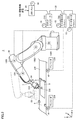
- FIG. 2 is a diagram showing an example of the appearance of the device to be simulated according to the present embodiment in relation to the control system.
- the control system 2 includes an information processing device 100, a PLC 200, a robot controller 310 for controlling the robot 30, and servomotor drivers 531 and 532.
- the information processing device 100 includes, for example, a terminal device such as a PC (Personal Computer) or a tablet terminal.
- Servo motor drivers 531 and 532 drive the corresponding servo motors 41 and 42.
- the information processing device 100 is connected to the PLC 200 via a network 80 described later. Any wired or wireless communication means may be adopted for the network 80.
- the PLC 200 and the information processing device 100 communicate according to, for example, USB (Universal Serial Bus).
- the information processing apparatus 100 provides a simulation environment for simulating the behavior of the control system 2, an environment for designing a control program for controlling the robot 30 and a machine related to transportation, and the like.
- the control program may be designed using the results of the simulation.
- the control program designed on the information processing apparatus 100 is sent to the PLC 200 via the field network.
- the PLC 200 executes the designed control program and gives target values to the robot controller 310 or the servomotor drivers 531 and 532, respectively, according to the execution result, thereby providing a machine related to the transfer of the robot 30 and the conveyor 230. Control.
- the robot controller 310 and the servo motor drivers 531 and 532 are connected to the PLC 200.
- the PLC 200, the robot controller 310, and the servo motor drivers 531 and 532 are connected by a daisy chain via the field network 22.
- the field network 22 for example, EtherCAT (registered trademark) is adopted.
- EtherCAT registered trademark
- the field network 22 is not limited to EtherCAT.
- the servomotor drivers 531 and 532 drive the servomotors 41 and 42 of the conveyor 230.
- Encoders 236 and 238 are arranged on the rotation axes of the servomotors 41 and 42. The encoder outputs the position (rotation angle), rotation speed, cumulative rotation speed, etc. of the servomotors to the PLC200 as feedback values of the servomotors 41 and 42.
- the robot 30 and the conveyor 230 move the work 232 while cooperating with each other.
- the movement of the work 232 will be described here for the sake of simplicity, the movement is not limited to the movement.
- the work 232 placed on the tray 9 may be processed by the robot 30.
- the servomotors 1301, 1302, 1303 and 1304 provided in the robot 30 (hereinafter, also collectively referred to as “robot servomotors”) and the robot controller for driving the robot servomotors are shown. 310 is illustrated.
- the servomotor drivers 531 and 532 for driving the servomotors 41 and 42 provided on the conveyor 230 will be illustrated.
- the behavior of the robot 30 changes in the three-dimensional space of the orthogonal X-axis, Y-axis, and Z-axis.
- the behavior of the conveyor 230 is defined in the same three-dimensional space as the robot 30, but is defined, for example, in the planes of the X and Y axes.
- the drive device is not limited to the servo driver, and the corresponding drive device is adopted according to the motor that is the driven device.
- the drive device when driving an induction motor or a synchronous motor, an inverter drive or the like may be adopted as the drive device.
- the robot controller 310 drives the robot servomotor of the robot 30.
- An encoder (not shown) is arranged on the rotation axis of each robot servomotor. The encoder outputs the position (rotation angle), rotation speed, cumulative rotation speed, etc. of the servomotor to the robot controller 310 as feedback values of the robot servomotor.
- the robot 30 and the conveyor 230 have movable parts that can be moved by a plurality of drive shafts. Each of these drive shafts is driven by a servomotor.
- the robot 30 has a plurality of arms driven by rotation of robot servomotors (servomotors 1301 to 1304). Each robot servomotor rotates to drive each corresponding arm.
- the robot controller 310 controls the drive of the robot servomotor, so that each arm is driven three-dimensionally. By driving each arm in this way, the behavior of the robot 30 is realized.
- the conveyor 230 and the tray 9 on the transport surface move as the servomotors 41 and 42 rotate.
- This amount of movement is determined by the amount of rotation (direction of rotation, angle) of the servomotors 41 and 42.
- each arm of the robot 30 is associated with a virtual axis, and the position of the robot 30 is determined from the position of each axis.
- the control system 2 controls each axis of the robot 30 according to a target position that changes in time series. As a result, the speed and trajectory of movement of each arm are changed so as to follow the target.
- the target position of the robot 30 is stored in advance in, for example, the PLC 200.
- the robot controller 310 receives a target position from the PLC 200, determines the rotation amount of each robot servomotor based on the received target position, and outputs a command value for designating the determined rotation amount to each robot servomotor.
- the servomotor rotation amount ( ⁇ A, ⁇ B, ⁇ C, ⁇ D) is set to the position in the three-dimensional virtual space of xyz.
- the three-dimensional coordinates P (x, y, z) which are the positions in the world coordinate system corresponding to the three-dimensional virtual space of the axis of the arm that picks the work 232 are shown, but the corresponding 3 of the other axes are shown.
- Dimensional coordinates can be calculated in the same way. Therefore, the behavior of the robot 30 in the three-dimensional virtual space can be shown by the time-series change of the three-dimensional coordinates P (x, y, z) of each arm.
- the three-dimensional coordinates P (x, y, z) of the axis of the arm that picks the work 232 are detected as "collision" in the three-dimensional virtual space described later. It is used to calculate the position of the object corresponding to the robot hand 210 for the purpose.
- the three-dimensional coordinates P (x, y, z) of other axes may be used to detect such a "collision", or the three-dimensional coordinates P (x, y, z) of two or more axes. You may use the combination of z).
- the conveyor 230 Similar to the robot 30, the conveyor 230 also changes in time series so that the movement speed and trajectory of the conveyor 230 indicate the target position so that the behavior of the conveyor 230 indicates the target behavior.
- the target position of the conveyor 230 is stored in the PLC 200 in advance.
- the servomotor drivers 531 and 532 determine the rotation amount of the servomotors 41 and 42 based on the target position from the PLC 200, and output a command value for specifying the determined rotation amount to the servomotors 41 and 42.
- the position of the conveyor 230 is also three-dimensional coordinates in the world coordinate system corresponding to the same three-dimensional virtual space as the robot 30. It can be converted to Q (x, y, 0).
- the behavior of the conveyor 230 in the three-dimensional virtual space can be shown by such a time-series change of the three-dimensional coordinates Q (x, y, 0).
- the position of the tray 9 placed on the transport surface of the conveyor 230 and the position of the work 232 placed on the tray 9 are determined from the position of the conveyor 230 in the three-dimensional virtual space.
- the z-axis of the three-dimensional coordinate Q is fixed at a value of 0, but other fixed values may be used.
- Time synchronization in the control system 2 will be described with reference to FIG.
- a plurality of devices connected to the field network 22, that is, the PLC 100, the robot controller 310, the servo motor drivers 531 and 532, and the robot hand 210 each have timers 90 to 94 time-synchronized with each other and are devices. By operating based on these timers, the transmission / reception timing of data including control commands is synchronized between the two. This timer corresponds to a counter that is synchronously incremented or decremented.
- timing represents the concept of time, time, or time when some event occurs.
- time synchronization means that the timers, time data, etc. of each device are synchronized.
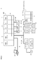
- FIG. 3 is a schematic view showing an example of the unit configuration of the control system 2 according to the present embodiment.
- FIG. 3 shows the overall configuration of the control system 2 with the configuration of FIG.
- the control system 2 includes a PLC200, a servomotor driver 531 and 532 connected to the PLC200 via a field network 22, a remote IO terminal 5, a robot controller 310, and an IO provided in the field.
- the device includes, for example, a photoelectric sensor 6, a proximity sensor 87 included in the stopper 8, and encoders 236 and 238.
- the PLC 200 includes an arithmetic unit 13, one or more IO units 14, and a special unit 17 that execute main arithmetic processing. These units are configured so that data can be exchanged with each other via the system bus 81, and power is supplied from the power supply unit 12.
- the simulation device 1 is connected to the calculation unit 13.
- the IO unit 14 collects detected values 61, 71, 237, and 239 from IO devices including the photoelectric sensor 6, the proximity sensor 87 of the stopper 8, the encoders 236, 238, and the like.
- the proximity sensor 87 non-contactly detects that the tray 9 with respect to the stopper 8 has approached a predetermined distance.
- the detected value from each IO device is set (written) in, for example, the corresponding bit of the memory included in the IO unit 14.
- the arithmetic unit 13 executes an operation of the control program using the value collected by the IO unit 14, and sets (writes) the value of the arithmetic result in the corresponding bit of the IO unit 14.
- the peripheral device or IO device operates by referring to the value of each bit of the IO unit 14. In this way, the PLC 200 can control the robot 30 or the conveyor 230 to be controlled while exchanging data with the IO device and peripheral devices via the IO unit 14.
- the special unit 17 has functions that the IO unit 14 does not support, such as input / output of analog data, temperature control, and communication by a specific communication method.
- the field network 22 may be connected to the robot controller 310, the servo motor drivers 531 and 532, and the remote IO terminal 5.
- the remote IO terminal 5 basically performs processing related to general input / output processing, similarly to the IO unit 14. More specifically, the remote IO terminal 5 includes a communication coupler 52 for performing processing related to data transmission in the field network 22, and one or more IO units 53. These units are configured to allow data to be exchanged with each other via the remote IO terminal bus 51.
- the servomotor drivers 531 and 532 are connected to the arithmetic unit 13 via the field network 22 and drive the servomotors 41 and 42 according to the command value from the arithmetic unit 13. Specifically, the servomotor drivers 531 and 532 receive command values such as a position command value, a speed command value, and a torque command value at a fixed cycle such as a control cycle synchronized with the timer 90 from the PLC 200. The arithmetic unit 13 generates these command values based on the detected values 237 and 239 from the encoders 236 and 238.
- the arithmetic unit 13 causes the robot 30 to perform pick and place by executing a predetermined control program with reference to the detected value from the IO device described above. Specifically, when the arithmetic unit 13 detects that the work 232 has approached a predetermined tracking area from the detection value 61 of the photoelectric sensor 6 and the detection value 71 of the proximity sensor 87, the robot arm causes the robot arm to perform pick and place.
- the control command 211 for the robot hand 210 and the control command 222 for the robot hand 210 are generated and output to the robot 30 via the robot controller 310.
- the state value of the robot 30 is referred to in addition to the detection values 61 and 71 from the IO device described above.
- FIG. 4 is a schematic diagram showing an example of a hardware configuration for realizing the simulation device 1 according to the present embodiment.
- the simulation device 1 is realized by executing a program required by the information processing device 100 as shown in FIG.
- the information processing device 100 has, as main components, an operating system (OS: Operating System), a processor 102 that executes various programs as described later, and a work area for storing data necessary for program execution on the processor 102.
- OS Operating System
- main memories 104 to be provided an operation unit 106 (operation reception unit) for receiving user operations such as a keyboard and a mouse, an output unit 108 for outputting processing results of a display 109, various indicators, a printer, etc., and various types including a network 80.
- It includes a network interface 110 connected to the network, an optical drive 112, a local communication interface 116 that communicates with an external device, and a storage 111.
- These components are connected to each other via an internal bus 118 or the like so that data can be communicated with each other.
- the information processing device 100 uses an optical drive 112 from a computer-readable recording medium 114 including an optical recording medium (for example, a DVD (Digital Versatile Disc)) for non-transiently storing a computer-readable program. , Read various programs and install them in storage 111 or the like.
- a computer-readable recording medium 114 including an optical recording medium (for example, a DVD (Digital Versatile Disc)) for non-transiently storing a computer-readable program.
- an optical recording medium for example, a DVD (Digital Versatile Disc)
- Various programs executed by the information processing device 100 may be installed via a computer-readable recording medium 114, but are installed in a manner of being downloaded from a server device (not shown) on the network via the network interface 110. You may.
- the storage 111 is composed of, for example, an HDD (Hard Disk Drive) or an SSD (Flash Solid State Drive), and stores a program executed by the processor 102.
- the storage 111 is a simulation program for realizing the simulation according to the present embodiment, which is a virtual time generation program 120, a relay program 121, a physical simulation program 122, a PLC simulation program 126, and a robot emulation program 130.
- the integration program 134 is stored.
- the storage 111 further stores an image processing program 136 that generates an image that displays an object arranged in the virtual space.
- the virtual time generation program 120 generates a virtual time for simulation.
- the simulation device 1 executes the simulation at a cycle based on the virtual time.
- the physics simulation program 122 calculates the behavior of the object corresponding to the device that operates in connection with the movement of the work 232.
- Equipment for which the behavior of the corresponding object is calculated by the physics simulation program 122 includes, for example, a photoelectric sensor 6, a conveyor 230, a tray 9, a stopper 8 and a robot hand 210 related to the transfer or movement of the work 232.
- the physics simulation program 122 is provided with physics simulation parameters 124 including parameters for defining the behavior of the object corresponding to such a device and parameters for defining the weight or shape of the work 232 and the like.
- the value of the physics simulation parameter 124 may be appropriately changed by a user operation, an integrated program 134, or the like.
- the equipment related to the transport or movement of the work 232 and the CAD (Computer Aided Design) data of the work 232 may be used.
- CAD Computer Aided Design
- the PLC simulation program 126 calculates the positions of the device and the work 232 from which the behavior of the corresponding object is calculated by the physics simulation program 122. The calculated position is given to the physics simulation program 122. The PLC simulation program 126 is given PLC parameters 128 including parameters necessary for calculating the above positions.
- the robot emulation program 130 functions as a simulator that reproduces the behavior of the robot 30 by objects.
- the robot emulation program 130 reproduces the pick-and-place of the work 232 by the robot 30 based on the result (behavior of the object) calculated by the physics simulation program 122.
- the robot emulation program 130 is given robot parameters 132 including parameters necessary for reproducing the behavior of the robot 30 with the corresponding objects.
- the relay program 121 provides a relay function for the physics simulation program 122 and the robot emulation program 130 to exchange data with each other.
- the relay program 121 is described, for example, by a script instruction, but is not limited to the relay program 121.
- the integrated program 134 executes a process for linking the physics simulation program 122, the PLC simulation program 126, the robot emulation program 130, and the relay program 121 with each other. Specifically, the integrated program 134 typically generates and updates virtual space information 105 that describes the state of objects in the virtual space on the main memory 104.
- the physics simulation program 122, the PLC simulation program 126, and the robot emulation program 130 refer to (read) the virtual space information 105 to execute each simulation process, and obtain the necessary information from the execution results as the virtual space information. Reflect in 105.
- the function provided by the integrated program 134 reproduces the behavior and processing of the device in the control system 2 including the device for transporting the work 232 and the robot 30 for moving the work 232 by pick and place.
- the image processing program 136 is provided with 3D visualized data 135 for displaying on the display 109 based on the virtual space information 105.
- the 3D visualization data 135 includes trajectory data 252 and image data 253.
- the image data 253 includes data for drawing an object corresponding to the simulated device, and the locus data 252 is calculated by performing an operation using a predetermined function on the position of each device indicated by the virtual space information 105.
- the time series data of the three-dimensional coordinates P (x, y, z) and the three-dimensional coordinates P (x, y, z) are included.
- the image processing program 136 uses such 3D visualization data 135 to display the behavior of the target object on the equipment related to the transfer of the work 232 and the work 232, the robot 30, and the robot hand 210 attached to the robot 30.
- Image data for three-dimensional drawing in a three-dimensional virtual space is generated and output to the display 109.
- the object is displayed on the display 109 according to the behavior calculated by the simulation, and the behavior of the device of the control system 2 is reproduced.
- the image data 253 may include CAD data and the like.
- FIG. 4 shows an example in which the simulation device 1 is realized by a single information processing device 100
- the simulation device 1 may be realized by linking a plurality of information processing devices.
- a part of the processing necessary for realizing the simulation device 1 may be executed by the information processing apparatus 100, and the remaining processing may be executed by a server (cloud) on the network or the like.
- FIG. 4 shows an example in which the simulation device 1 is realized by the processor 102 executing one or a plurality of programs. However, some of the processes and functions required to realize the simulation device 1 are ASICs. It may be implemented using (Application Specific Integrated Circuit) or FPGA (Field-Programmable Gate Array).
- FIG. 5 illustrating an example of the functional configuration of the simulation device 1 according to the present embodiment is a schematic diagram showing an example of the functional configuration for realizing the simulation device 1 according to the present embodiment.
- the function shown in FIG. 5 is typically a program (virtual time generation program 120, relay program 121, physical simulation program 122, PLC simulation program 126, robot emulation program 130, integrated program 134) of the processor 102 of the information processing apparatus 100. And the image processing program 136, etc.).
- the simulation apparatus 1 includes a virtual space information management module 150, a PLC simulator 152, a cycle generation module 154, a physical simulator 156, a relay module 158, a robot emulator 160, and the like. Includes 3D visualizer 164 and.
- the virtual space information management module 150 is realized by executing the integrated program 134 (FIG. 4), and defines information on the behavior (position, posture, etc.) of each object in the virtual space on which the simulation is performed. Manage 105.
- the PLC simulator 152 is realized by executing the PLC simulation program 126 (FIG. 4), and calculates the behavior of the object corresponding to the device related to the transfer of the work 232 according to the physical simulation parameter 124.
- the information calculated by the PLC simulator 152 is reflected in the virtual space information 105.
- the PLC simulator 152 is a program for estimating the behavior of the device related to the transportation of the work 232, and corresponds to a simulation program including a plurality of instructions included in the PLC program. These plurality of instructions may include a group of instructions for controlling the behavior of the equipment involved in the transfer included in the PLC program.
- the PLC program is written in a programming language described in, for example, a cyclic execution type language (for example, a ladder language).
- command values for controlling the servomotors 41 and 42 of the conveyor 230 are generated and stored in the virtual space information 105. To. Such command values are shown as shared data 12A (FIG. 1).
- the robot emulator 160 calculates the behavior of the robot 30 that moves the work 232 arranged in the virtual space. More specifically, the robot emulator 160 is realized by executing the robot emulation program 130 (FIG. 4) based on the robot parameter 132. The information on the behavior of the robot 30 calculated by the robot emulator 160 is reflected in the virtual space information 105. The robot emulator 160 performs a simulation by regarding the arm of the robot 30 and the robot hand 210 attached to the tip thereof as an integral rigid body.
- the robot emulation program 130 includes a group of instructions included in the program of the robot controller 310.
- This command group includes commands of a robot program having a command code for causing the robot 30 to operate the work 232. These commands calculate the trajectory of the target of the robot 30 based on the shared data 12A of the virtual space information 105 (including the output data of the PLC simulator 152), and the command value indicating the behavior of each axis based on the calculated trajectory, etc. Includes commands to calculate.
- the command value for each axis of the robot 30 is generated, and the virtual space information 105 is generated. It is stored as data in.
- Such a command value is shown as shared data 12A (FIG. 1).
- the command values generated by the PLC simulator 152 and the robot emulator 160 have the estimated behavior of the robot 30 and the equipment (conveyor 230 servomotors 41, 42, etc.) for transporting the work 232 of the conveyor 230. Can be shown. Further, the PLC simulator 152 and the robot emulator 160 each calculate a new command value based on the command value calculated by the other via the shared data 12A of the virtual space information 105. Therefore, the behavior of the servomotor estimated from the command value calculated in this way can indicate the mutually coordinated operation of the equipment related to the transfer of the robot 30 and the work 232.
- the work behavior simulator 155 calculates the behavior of one or more work 232 objects arranged in the virtual space. Specifically, the work behavior simulator 155 is realized by executing the physics simulation program 122 (FIG. 4). The work behavior simulator 155 calculates the behavior of the work 232 arranged in the virtual space according to the information on the behavior of the object corresponding to the transport device of the work 232 calculated by the PLC simulator 152, and uses the calculation result to obtain the work behavior simulator 155. Update the behavior. In calculating the behavior of the work 232, the work behavior simulator 155 calculates the position, posture, moving speed, moving direction, and the like of the work 232. The position and posture of the work 232 are calculated based on the work parameters arbitrarily set by the user or the like. The position and orientation information of the work 232 calculated by the work behavior simulator 155 is reflected in the virtual space information 105. Work parameters can also be included in physics simulation parameters 124.
- the physics simulator 156 is realized by executing the physics simulation program 122 (FIG. 4).
- the physics simulator 156 calculates the behavior (position, posture, moving speed, moving direction, etc.) of objects corresponding to the device for transporting or moving the work 232 according to the physics simulation parameter 124, and virtual space between these objects. Detects collisions in.
- the collision detection result is output to the PLC simulator 152 or the robot emulator 160.
- the physics simulator 156 detects the presence or absence of collision between objects based on the positional relationship between objects calculated in the virtual space.
- “Collision” includes, for example, that the distance between the coordinates P of an object and the coordinates Q of another object in virtual space is a specific distance including, for example, a distance equal to or less than a threshold value.
- the "collision” includes that the locus connecting the coordinate P and the next-order coordinate P intersects the locus connecting the coordinate Q corresponding to the coordinate P and the next-order coordinate Q.
- the threshold is a value based on the size (width, height, etc.) of each object. For example, the threshold or object size can be included in the physics simulation parameter 124.
- the positional relationship for detecting "collision" is not limited to these positional relationships.
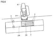
- FIG. 6 is a diagram illustrating a simulation target of the physics simulator 156 according to the present embodiment.
- Objects that the physics simulator 156 calculates behavior and detects collisions include a photoelectric sensor 6, a stopper 8, a tray 9, a robot hand 210, a conveyor 230, and a work 232, as shown in FIG.
- the physics simulator 156 calculates the behavior of these objects such as the position and posture according to a predetermined physics calculation, and detects the collision of the objects based on the calculated behavior such as the position.
- the physics simulator 156 sets the parameter 127 of the mass of the object to zero among the parameters used for this physics calculation, and executes the calculation.
- the meaning of setting the mass to zero is as follows. That is, when the mass parameter 127 is not zero, the physics simulator 156 calculates the components of the mechanical action on the object such as velocity, acceleration, and gravity based on the mass of the object by physics calculation, and the calculation is performed. Depending on the components of the mechanical action, the physics simulator 156 will calculate (update) the position of the object in the next time step. On the other hand, in the present embodiment, the PLC simulator 152 and the robot emulator 160 determine (control) the position of each object.
- the simulation device 1 sets the parameter 127 of the mass of each object used for the physical calculation of the physics simulator 156 to zero. Will be done.
- Velocity, acceleration, gravity, etc. are also zero for objects whose position (behavior) is calculated with the mass set to zero by physics calculation, so even if these objects collide with each other, the mechanical components (repulsion, etc.) are calculated in physics calculation. Since the component such as the bounce of the object such as is calculated as zero (invalidation), the collision of the object can be detected based on the position of the object in which the mechanical action is invalidated.
- the work tracking module 162 is realized by executing the robot emulation program 130, and tracks the work 232 picked and placed by the robot 30 in the virtual space based on the behavior information of the robot 30 from the robot emulator 160.
- the position information (work position) of the work 232 tracked by the work tracking module 162 is reflected in the virtual space information 105.
- the 3D visualizer 164 corresponds to an image generation unit that generates an image that visualizes the virtual space.
- the 3D visualizer 164 is based on the virtual space information 105 managed by the virtual space information management module 150, and the behavior of each object in the virtual space (work 232, equipment related to the transfer of the work 232, robot 30, robot hand 210, etc.). To visualize.
- the cycle generation module 154 is realized by executing the virtual time generation program 120.
- the cycle generation module 154 outputs a signal ST synchronized with the output of the timer to other parts based on the output of the timer (not shown) included in the processor 102.
- Each unit executes a process or a program in synchronization with a cycle in which the signal ST is output from the cycle generation module 154 (hereinafter, referred to as a predetermined time step).
- a predetermined time step a cycle in which the signal ST is output from the cycle generation module 154
- the cycle of the signal ST may be determined based on the communication cycle (hereinafter, also referred to as “control cycle”) of the field network 22 of the control system 2 of FIG.
- control system 2 By linking each function as shown in FIG. 5, the behavior of the system to be simulated (for example, control system 2) can be reproduced with high accuracy.
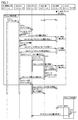
- FIG. 7 is a diagram schematically showing an example of a processing sequence of the simulation apparatus 1 according to the present embodiment.
- the processing of each part of the simulation apparatus 1 is shown in association with data or commands exchanged between the cycle generation module 154, the PLC simulator 152, the robot emulator 160, the relay module 158, and the physics simulator 156.
- the data exchanged between these parts includes the positions corresponding to the coordinates of the world coordinate system shared between these parts.
- these exchanged data or commands may include data or commands exchanged via the virtual space information 105, but in FIG. 7, for the sake of explanation, the virtual space information 105 and the virtual space information management module 150 The illustration is omitted.
- the simulation apparatus 1 sets the mass parameter 127 of the object corresponding to the work 232 and the device for transporting or moving the work 232 shown in FIG. 6 among the physics simulation parameters 124 to zero (see FIG. 7). Step T1). After that, the simulation device 1 activates each unit to start the processing after step T2.
- the process of step T2 is repeatedly executed at predetermined time steps based on the signal ST output by the cycle generation module 154.
- the 3D visualizer 164 performs a process (step T3) of generating an image for drawing the 3D image on the display 109 at a cycle longer than the time step.
- the simulation device 1 generates a 3D image showing the simulation result based on the virtual space information 105 and the 3D visualization data 135 showing the result of repeatedly executing the periodic processing of step T2 a plurality of times, and displays 109. Can be displayed on.
- the cycle generation module 154 is activated when an activation command is received from the user via the operation unit 106, and starts outputting the signal ST. As a result, the periodic processing of step T2 starts. Further, at the start of the periodic processing, the relay module 158 outputs a command for initializing the position (coordinates) of the object based on the image measurement parameter 129 to the physical simulator 156 (step S1). The physics simulator 156 sets the position (coordinates) of each object to the initial position of the virtual space information 105 according to the command.
- step T2 When the cycle processing (step T2) is started, the cycle generation module 154 outputs a command tick for driving the servomotor (step S3).
- the PLC simulator 152 executes the simulation program according to the command tick from the cycle generation module 154, generates and outputs the command tick for making the robot 30 stand by (step S5), and turns ON the input variable of the photoelectric sensor 6.
- Set step S9.
- a series of behaviors are calculated in which the servomotors 41 and 42 are driven to move the conveyor 230, and the position of the conveyor 230 is detected by the photoelectric sensor 6.
- the PLC simulator 152 further updates the position of the tray 9 on the transport surface as the conveyor 230 moves (step S11).
- the physics simulator 156 performs arithmetic processing for collision detection in response to the update (step S13). Specifically, the physics simulator 156 updates the position of the object in the tray 9 set in step S1 by overwriting the position of the tray 9 after the update of the virtual space information 105, and updates the position of the tray 9 after the update. Based on the position of and the position of the photoelectric sensor 6, the presence or absence of the above-mentioned collision in the world coordinate system is detected (step S13). Here, the physics simulator 156 detects a collision between the objects of the tray 9 and the photoelectric sensor 6. The physics simulator 156 outputs that the collision between the tray 9 and the photoelectric sensor 6 has been detected (step S15).
- the PLC simulator 152 updates (changes) the position of the tray 9 so that the tray 9 approaches the stopper 8 (step S19), and closes the stopper 8.
- a command (that is, updating the position of the stopper 8) is output (step S23).
- the physics simulator 156 performs arithmetic processing for collision detection in response to the command in step S23 (step S25). Specifically, the physics simulator 156 updates the positions of the objects of the stopper 8 and the tray 9 set in step S1 by overwriting the updated positions of the virtual space information 105, respectively, and updates the positions. Based on the position of the tray 9 and the position of the stopper 8, the presence or absence of the above-mentioned collision in the world coordinate system is detected (step S25). Here, the physics simulator 156 detects a collision between the objects of the tray 9 and the stopper 8. The physics simulator 156 outputs that the collision between the tray 9 and the stopper 8 has been detected (step S29).
- the PLC simulator 152 outputs a command to the robot 30 to set the position of the work 232 in response to the output from the physics simulator 156 (detection that the tray 9 has collided with the stopper 8) (step S33).
- the position of the work 232 indicates a position based on the position of the updated tray 9 in step S19.
- the relay module 158 is a data for calculating the behavior of picking the work 232 with the robot hand 210 between the physical simulator 156 and the robot emulator 160 in response to the command output from the PLC simulator 152 in step S33.
- the process for relaying the exchange is started (step S35).
- the relay module 158 outputs a command to pick the work 232 with the robot hand 210 (step S39).
- the robot emulator 160 updates the position of the robot hand 210 based on the position of the work 232 in response to the command output from the relay module 158 (step S43).
- the physics simulator 156 executes a collision detection calculation based on the updated position of the robot hand 210 and the position of the work 232 (step S45), and determines whether the robot hand 210 has collided with the work 232 based on the calculation result. To detect.
- the relay module 158 determines that the robot hand 210 has collided with the work 232 based on the output of the physics simulator 156 (step S47). In response to the determination, the relay module 158 groups (relates to each other) information related to the behavior of the objects of the robot hand 210 and the work 232 in the virtual space information 105 (step S49). The relay module 158 then sets a variable indicating the closed state of the robot hand 210 to ON (step S53).
- the PLC simulator 152 outputs a command to move the work 232 to the place location (position of the table 55) while being picked in response to the relay module 158 setting the hand variable of the robot hand 210 to ON. (Step S55).
- the position of the table 55 is set in the robot emulator 160. As a result, the process in the time step of step T2 ends.
- the robot emulator 160 In response to the command from the PLC simulator 152 (command in step S55), the robot emulator 160 outputs a command to update the positions of the robot hand 210 and the work 232 to the physical simulator 156 (step S57), and completes the place. Is output to the relay module 158 (step S61). In response to the command (step S57) from the robot emulator 160, the physics simulator 156 updates the positions of the robot hand 210 and the work 232 of the physics simulator 156 so as to indicate the positions corresponding to the placed positions. ..
- step T2 is executed in the same manner as the procedure described above.
- step T3 the 3D visualizer 164 acquires the positions of the work 232 and each device (FIG. 6) calculated by the physical simulator 156 from the physical simulator 156 (step S73), and the acquired positions correspond to the image data 253.
- Rendering processing is performed based on the 3D visualization data 135 including the object data (step S75), and the position indicated by the behavior of the robot 30 calculated by the robot emulator 160 is acquired from the virtual space information 105 (step). S77).
- the 3D visualizer 164 generates image data to be drawn on the display 109 from the object data after the rendering process and the position of the robot 30.
- step T2 if no collision is detected in each of the collision detection processes (steps S13, S25 and S45) in the physics simulator 156, the subsequent processes in step T2 may be skipped.
- the simulation device 1 counts the time steps until the robot hand 210 is detected to collide with the work 232 (step S45), so that the simulated PLC program and the robot program control system 2 (step S45).
- the tact time when the FIG. 2) is driven can be estimated.
- one physics simulator 156 can be shared by a plurality of types of robot hands 210 mounted on the robot 30. ..
- the PLC simulator 152, the robot emulator 160, the relay module 158, and the physics simulator 156 can be time-synchronized with each other based on the signal ST from the cycle generation module 154, the same is applied in each simulation when the simulations are repeatedly executed. Collision detection can be reproduced.
- the positions of the robot hand 210 and the work 232 were calculated by the physics simulator 156, but these positions may be calculated by the robot emulator 160. The user may also specify whether these positions should be calculated by the robot emulator 160 or the physics simulator 156.
- FIG. 8 is a diagram showing an example of a display according to the present embodiment.
- FIG. 8 shows, for example, a case where the processing of the 3D visualizer 164 is started when it is detected that the robot hand 210 collides with the work 232.
- the image generated by the 3D visualizer 164 draws a 3D image in the area 1092 of the display 109.
- a part of the simulated program is displayed in the area 1091 of the display 109 of FIG.
- the 3D image of the area 1092 shows a state in which a collision 1093 between the robot hand 210 and the work 232 has been detected (step S45 in FIG. 7).
- FIG. 9 is a diagram schematically showing an example of a combination of the simulation device 1 and the actual machine according to the present embodiment.
- the behavior of the device with respect to the pick of the work 232 in the tracking area 231 can be calculated.
- the calculated behavior is not limited to pick-related behavior.
- the simulation device 1 shows a route for acquiring at least one data of both the robot 30 and the PLC 200. It can be an actual machine provided in a production line such as 2.
- FIG. 9 shows a scene in which the information processing device 100 on which the simulation device 1 is mounted is connected to the PLC 200, which is an example of the actual device, via the network 80.
- the actual PLC200 is connected to the network 220 of the FA (factory automation) system, but the robot 30 is not connected.
- the simulation device 1 of the information processing device 100 calculates the behavior of the robot 30 using the data from the PLC 200 of the actual machine.
- the simulation device 1 does not start the PLC simulator 152 (or replaces the PLC simulator 152), and data indicating a command value from the PLC 200 operating as an actual machine to the device for transporting the work 232 and the like. Is received, and the received data is set in the virtual space information 105 (shared data 12A).
- the object corresponding to the robot 30 that operates in cooperation with the actual PLC 200 while exchanging data between the robot emulator 160 and the actual PLC 200 via the virtual space information 105.
- the behavior is estimated, and the collision is detected by the physics simulator 156 based on the estimated behavior.
- control cycle related to the operating speed of the actual machine is generally shorter than the cycle of the time step of the simulation device 1, when the simulation device 1 is combined with the actual machine as shown in FIG. 9, the simulation device 1 has the simulation time. Adjust the control cycle of the actual machine so that it matches the steps.
- the combination shown in FIG. 9 is a combination of the actual PLC200 and the robot emulator 160, but is not limited to this, and may be a combination of the actual robot 30 and the PLC simulator 152.
- Robot 30 cable simulation> it is possible to provide a cable simulation for calculating (reproducing) the behavior of the cable accompanying the operation of the robot 30.
- the behavior of a cable attached to the robot 30 that can be attached to the robot 30 and a device related to the cable is simulated.
- a position for guiding a cable that is, a position of a robot hand 210, a position of rings 351 and 352,353 (also referred to as a guide position), and adjacent guide positions are connected to each other. Cables 341, 342 and 343 are shown.
- the simulation device 1 detects interference between these cables and the robot 30, that is, collisions between the cables and the robot 30 (more specifically, the arm).
- the rings 351 and 352, 353 and the cables 341, 342 and 343 can be treated as an example of an accessory device mounted on the robot 30.
- the robot emulator 160 calculates the position of the robot hand 210 and the position (guide position) of the rings 351 and 352,353 when calculating the behavior of the robot 30.
- the physics simulator 156 calculates each position of the robot hand 210 and the rings 351, 352, 353 by performing a physical calculation with the mass set to zero at the guide position calculated by the robot emulator 160.
- the physics simulator 156 calculates the behavior (position, posture, etc.) of the cables 341, 342, 343 with the mass as zero based on each position calculated in this way by using a predetermined function.
- the physics simulator 156 detects a collision between the cable and another member (adjacent cable, etc.) based on the calculated positions of the cables 341, 342, and 343.
- the length and mounting position (guide position) of the cables 341, 342 and 343 are determined based on the result of collision detection of the cables 341, 342 and 343. It becomes possible to detect suitability.
- a simulation device (1) that calculates the behavior of the device.
- a first behavior calculation unit (160) that calculates the behavior of the first object arranged in the virtual space corresponding to the first device (30) to which the accessory device (210) is attached, and
- a second behavior calculation unit (158) that calculates the behavior of the second target in the virtual space corresponding to the second device is provided.
- the second device includes the accessory device.
- the first behavior calculation unit calculates the behavior of the first target corresponding to the first device to which the accessory device is attached in the time step, and then the behavior of the first target is calculated.
- the simulation device according to configuration 1 wherein the accessory device includes a device that adds an operation function for operating a work to the first device by being attached.
- the second behavior calculation unit includes a physics simulator.
- the first device includes a robot.
- the behavior of the first object calculated by the first behavior calculation unit includes the position of the first object in the virtual space.
- the simulation apparatus according to configuration 3 or 4 wherein the physics simulator calculates the behavior of the second target according to a physics calculation using the first position calculated by the first behavior calculation unit.
- [Structure 6] The simulation apparatus according to configuration 5, wherein the physics simulator invalidates the generation of a force on the second object and executes the physics calculation.
- the behavior calculated for the second object corresponding to the accessory device includes the position of the second object in the virtual space.
- the second behavior calculation unit further The simulation apparatus according to any one of configurations 1 to 6, which detects a collision (1093) between the position of the second target in the virtual space of the accessory device and the position of a predetermined target in the virtual space. .. [Structure 8]
- a third behavior calculation unit (152) for calculating the behavior of the third object arranged in the virtual space corresponding to the third device (200) is further provided.
- the third device operates in cooperation with the first device while exchanging data with the first device.
- the simulation apparatus according to any one of configurations 1 to 7, wherein the simulation apparatus acquires data (12A) exchanged between the first apparatus and the third apparatus from an actual machine provided on a production line. Simulation equipment.
- [Structure 9] The simulation apparatus according to any one of configurations 1 to 8, wherein the accessory device includes a cable that can be attached to the first device.
- [Structure 10] The simulation apparatus according to any one of configurations 1 to 9, further comprising an image generation unit (164) that generates an image that visualizes the virtual space.
- [Structure 11] A simulation program for causing a computer (100) to execute a method of calculating the behavior of a device. The method is The first behavior calculation step for calculating the behavior of the first target placed in the virtual space corresponding to the first device to which the accessory device is attached, and the first behavior calculation step.
- a second behavior calculation step for calculating the behavior of the second target in the virtual space corresponding to the second device is provided.
- the second device includes the accessory device.
- the behavior of the first target corresponding to the first device to which the accessory device is attached is calculated in the first behavior calculation step, and then in the second behavior calculation step.
- This is a simulation method for calculating the behavior of equipment.
- the first step of calculating the behavior of the first target placed in the virtual space corresponding to the first device to which the accessory device is attached, and A second step of calculating the behavior of the second object in the virtual space corresponding to the second device is provided.
- the second device includes the accessory device.
- the behavior of the first object corresponding to the first device to which the accessory device is attached is calculated in the first step, and then the first step is performed in the second step.
- a simulation method in which the behavior of the accessory device mounted on the first device is calculated based on the behavior of the first target calculated in the step.
- Simulator 158 relay module, 160 robot emulator, 162 work tracking module, 164 3D visualizer, 210 robot hand, 230 conveyor, 232 work, 236,238 encoder, 310 robot controller, 341,342,343 cable, 351,352,353 Ring, 531 and 532 servo motor driver, 1093 collision.
Landscapes
- Engineering & Computer Science (AREA)
- Physics & Mathematics (AREA)
- General Physics & Mathematics (AREA)
- Automation & Control Theory (AREA)
- Robotics (AREA)
- Mechanical Engineering (AREA)
- Theoretical Computer Science (AREA)
- Manufacturing & Machinery (AREA)
- Human Computer Interaction (AREA)
- Computer Hardware Design (AREA)
- Evolutionary Computation (AREA)
- Geometry (AREA)
- General Engineering & Computer Science (AREA)
- Manipulator (AREA)
- Programmable Controllers (AREA)
Abstract
Description
上述の開示によれば、第1の挙動算出部に変更を加えずに、物理シミュレータを流用して第2の機器の挙動算出部を提供することができる。
上述の開示によれば、第1の機器の装着可能なケーブルに対応する対象の挙動を含むシミュレーションを実現できる。
まず、本発明が適用される場面の一例について説明する。
シミュレーション装置1は、生産ラインに備えられる図2の制御システム2が制御する実機である機器の挙動を推定する。このように挙動の推定がなされる対象の機器として、実施の形態では、可動のコンベア230とロボット30を例示するが、対象の機械はこれらに限定されない。ロボッと30は、アームの先端に、コネクタ7を介してロボットハンド210が脱着自在に装着される。ロボットハンド210は、例えば平行ハンド、多指ハンド、多指関節ハンドなどの複数種類を含む。ロボットハンド210の種類は、これに限定されず、例えば吸着式によりワーク232をピックおよびプレースする種類も含み得る。ロボット30には、ワーク232または工程に応じた種類のロボットハンド210が装着される。
図2を参照して、制御システム2におけるロボット30とコンベア230の制御について説明する。ロボット30とコンベア230は、上記に述べたように、複数の駆動軸により移動可能な可動部を有する。これらの各駆動軸は、サーボモータによって駆動される。具体的には、ロボット30は、ロボットサーボモータ(サーボモータ1301~1304)が回転することで駆動される複数のアームを有している。ロボットサーボモータは、それぞれ回転することで、対応する各アームを駆動する。ロボットコントローラ310がロボットサーボモータの駆動を制御することで、各アームが3次元に駆動される。このような各アームの駆動により、ロボット30の挙動が実現される。同様に、コンベア230も、サーボモータ41,42が回転することでコンベア230および搬送面上のトレイ9が移動する。この移動量(移動の速度、向き、距離など)は、サーボモータ41,42の回転量(回転の向き、角度)により決まる。このようなサーボモータ41,42の駆動により、コンベア230およびトレイ9などの機器の挙動が実現される。
本実施の形態にかかるロボット30の各アームに相当する軸の3次元仮想空間における位置を算出する過程の一例を説明する。本実施の形態では、3次元仮想空間における座標系として、ロボット30およびPLC200などの各部が共通して備えるワールド座標系を例示する。ワールド座標系における位置を算出する際に、本実施の形態では、サーボモータ1301の回転量をαA、サーボモータ1302の回転量をαB、サーボモータ1303の回転量をαCおよびサーボモータ1304の回転量をαDとして示す。サーボモータ回転量(αA、αB、αC、αD)に対し、所定関数を用いて演算を施すことで、サーボモータ回転量(αA、αB、αC、αD)をxyzの3次元仮想空間における位置に変換することができる。図2では、例えばワーク232をピックするアームの軸の3次元仮想空間に対応したワールド座標系における位置である3次元座標P(x、y、z)を示すが、他の軸の対応する3次元座標も同様に算出することができる。たがって、各アームの3次元座標P(x、y、z)の時系列の変化によりロボット30の3次元仮想空間における挙動を示すことができる。
図2を参照して、制御システム2における時刻同期を説明する。制御システム2において、フィールドネットワーク22に接続される複数の機器、すなわちPLC100、ロボットコントローラ310、サーボモータドライバ531,532およびロボットハンド210は、互いに時刻同期されたタイマ90~94をそれぞれ有し、機器の間では、これらタイマに基き動作することで、制御指令を含むデータの送受信タイミングが同期されている。このタイマは、同期してインクリメントまたはデクリメントされるカウンタに相当する。
図3は、本実施の形態にかかる制御システム2のユニット構成の一例を示す模式図である。図3には、図2の構成を備える制御システム2の全体的な構成が示される。
次に、本実施の形態に係るシミュレーション装置1のハードウェア構成の一例について説明する。
次に、本実施の形態に係るシミュレーション装置1の機能構成の一例について説明する図5は、本実施の形態に係るシミュレーション装置1を実現するための機能構成の一例を示す模式図である。図5に示す機能は、典型的には、情報処理装置100のプロセッサ102がプログラム(仮想時刻生成プログラム120、中継プログラム121、物理シミュレーションプログラム122、PLCシミュレーションプログラム126、ロボットエミュレーションプログラム130、統合プログラム134および画像処理プログラム136など)を実行することで実現される。
図7は、本実施の形態にかかるシミュレーション装置1の処理のシーケンスの一例を模式的に示す図である。図7では、シミュレーション装置1の各部の処理が、周期生成モジュール154、PLCシミュレータ152、ロボットエミュレータ160、中継モジュール158および物理シミュレータ156の間で遣り取りされるデータまたは指令と関連付けて示される。これら各部間で遣り取りされるデータは、これら各部間で共有するワールド座標系の座標に対応した位置を含む。また、これら遣り取りされるデータまたは指令は、仮想空間情報105を介して遣り取りされるデータまたは指令を含み得るが、図7では、説明のために、仮想空間情報105および仮想空間情報管理モジュール150の図示は略されている。
図8は、本実施の形態にかかる表示の一例を示す図である。図8では、例えば、ロボットハンド210がワーク232に衝突したことが検出された時点で、3Dビジュアライザ164の処理が開始されるケースを示している。図8を参照して、3Dビジュアライザ164が生成した画像により、ディスプレイ109の領域1092において3D画像が描画される。図8のディスプレイ109の領域1091には、シミュレートされているプログラムの一部が表示されている。領域1092の3D画像は、ロボットハンド210とワーク232との間の衝突1093が検出(図7のステップS45)された状態を示している。
図9は、本実施の形態にかかるシミュレーション装置1と実機の組合せの一例を模式的に示す図である。図9によれば、実機と仮想の機器(PLC200またはロボット30)とを組合せたケースにおいて、例えば、トラッキングエリア231におけるワーク232のピックに関する当該機器の挙動を算出することができる。算出される挙動は、ピックに関連した挙動に限定されない。具体的には、ロボット30とデータ(共有データ12A)を遣り取りしながら連携動作するPLC200とについて、シミュレーション装置1は、ロボット30とPLC200の両者の少なくとも一方のデータを取得するための経路を、図2のような生産ラインに備えられる実機とすることができる。
本実施の形態では、ロボット30の動作に伴うケーブルの挙動を算出(再現)するためのケーブルシミュレーションを提供することができる。本実施の形態では、ロボット30に付属するケーブルであってロボット30に装着可能なケーブルと、ケーブルに関連する機器の挙動をシミュレーションする。
上述したような本実施の形態は、以下のような技術思想を含む。
[構成1]
機器の挙動を算出するシミュレーション装置(1)であって、
付属機器(210)が装着された第1の機器(30)に対応する仮想空間に配置された第1の対象の挙動を算出する第1の挙動算出部(160)と、
第2の機器に対応する前記仮想空間における第2の対象の挙動を算出する第2の挙動算出部(158)と、を、備え、
前記第2の機器は、前記付属機器を含み、
所定のタイムステップ毎(ST)に、当該タイムステップにおいて前記第1の挙動算出部が前記付属機器が装着された第1の機器に対応する前記第1の対象の挙動を算出し、その後、前記第2の挙動算出部が当該算出された前記第1の対象の挙動に基づき前記第1の機器に装着されている前記付属機器の挙動を算出する、シミュレーション装置。
[構成2]
前記付属機器は、装着されることにより前記第1の機器にワークを操作する操作機能を付加する機器を含む、構成1に記載のシミュレーション装置。
[構成3]
前記第2の挙動算出部は、物理シミュレータを含む、構成1または2に記載のシミュレーション装置。
[構成4]
前記第1の機器は、ロボットを含み、
前記第1の挙動算出部は、前記ロボットにワークを操作させる指令コードを有したロボットプログラムのエミュレーションを実行する、構成3に記載のシミュレーション装置。
[構成5]
前記第1の挙動算出部によって算出される前記第1の対象の挙動は、前記仮想空間における前記第1の対象の位置を含み、
前記物理シミュレータは、前記第1の挙動算出部によって算出される前記第1の位置を用いた物理演算に従い、前記第2の対象の挙動を算出する、構成3または4に記載のシミュレーション装置。
[構成6]
前記物理シミュレータは、前記第2の対象に対する力の発生を無効化して前記物理演算を実施する、構成5に記載のシミュレーション装置。
[構成7]
前記付属機器に対応の第2の対象について算出された挙動は、前記仮想空間における当該第2の対象の位置を含み、
前記第2の挙動算出部は、さらに、
前記付属機器の前記仮想空間における前記第2の対象の位置と、当該仮想空間における所定対象の位置とから両者の衝突(1093)を検出する、構成1から6のいずれか1に記載のシミュレーション装置。
[構成8]
第3の機器(200)に対応する仮想空間に配置された第3の対象の挙動を算出する第3の挙動算出部(152)を、さらに備え、
前記第3の機器は、前記第1の機器とデータを遣り取りしながら当該第1の機器と連携動作し、
前記シミュレーション装置は、前記第1の機器と前記第3の機器との間で遣り取りされるデータ(12A)を、生産ラインに備えられる実機から取得する、構成1から7のいずれか1に記載のシミュレーション装置。
[構成9]
前記付属機器は、前記第1の機器に取り付け可能なケーブルを含む、構成1から8のいずれか1に記載のシミュレーション装置。
[構成10]
前記仮想空間をビジュアル化した画像を生成する画像生成部(164)を、さらに備える、構成1から9のいずれか1に記載のシミュレーション装置。
[構成11]
コンピュータ(100)に機器の挙動を算出する方法を実行させるためのシミュレーションプログラムであって、
前記方法は、
付属機器が装着された第1の機器に対応する仮想空間に配置された第1の対象の挙動を算出する第1の挙動算出ステップと、
第2の機器に対応する前記仮想空間における第2の対象の挙動を算出する第2の挙動算出ステップと、を、備え、
前記第2の機器は、前記付属機器を含み、
所定のタイムステップ毎に、前記第1の挙動算出ステップでは前記付属機器が装着された第1の機器に対応する前記第1の対象の挙動が算出され、その後、前記第2の挙動算出ステップでは当該算出された前記第1の対象の挙動に基づき前記第1の機器に装着されている前記付属機器の挙動が算出される、シミュレーションプログラム。
[構成12]
機器の挙動を算出するシミュレーション方法であって、
付属機器が装着された第1の機器に対応する仮想空間に配置された第1の対象の挙動を算出する第1のステップと、
第2の機器に対応する前記仮想空間における第2の対象の挙動を算出する第2のステップと、を、備え、
前記第2の機器は、前記付属機器を含み、
所定のタイムステップ毎に、前記第1のステップでは前記付属機器が装着された第1の機器に対応する前記第1の対象の挙動が算出され、その後、前記第2のステップでは、前記第1のステップにおいて算出された前記第1の対象の挙動に基づき前記第1の機器に装着されている前記付属機器の挙動が算出される、シミュレーション方法。
Claims (12)
- 機器の挙動を算出するシミュレーション装置であって、
付属機器が装着された第1の機器に対応する仮想空間に配置された第1の対象の挙動を算出する第1の挙動算出部と、
第2の機器に対応する前記仮想空間における第2の対象の挙動を算出する第2の挙動算出部と、を、備え、
前記第2の機器は、前記付属機器を含み、
所定のタイムステップ毎に、当該タイムステップにおいて、
前記第1の挙動算出部が前記付属機器が装着された第1の機器に対応する前記第1の対象の挙動を算出し、その後、前記第2の挙動算出部が当該算出された前記第1の対象の挙動に基づき前記第1の機器に装着されている前記付属機器の挙動を算出する、シミュレーション装置。 - 前記付属機器は、装着されることにより前記第1の機器にワークを操作する操作機能を付加する機器を含む、請求項1に記載のシミュレーション装置。
- 前記第2の挙動算出部は、物理シミュレータを含む、請求項1または2に記載のシミュレーション装置。
- 前記第1の機器は、ロボットを含み、
前記第1の挙動算出部は、前記ロボットにワークを操作させる指令コードを有したロボットプログラムのエミュレーションを実行する、請求項3に記載のシミュレーション装置。 - 前記第1の挙動算出部によって算出される前記第1の対象の挙動は、前記仮想空間における前記第1の対象の位置を含み、
前記物理シミュレータは、前記第1の挙動算出部によって算出される前記第1の対象の位置を用いた物理演算に従い、前記第2の対象の挙動を算出する、請求項3または4に記載のシミュレーション装置。 - 前記物理シミュレータは、前記第2の対象に対する力の発生を無効化して前記物理演算を実施する、請求項5に記載のシミュレーション装置。
- 前記付属機器に対応の前記第2の対象について算出された挙動は、前記仮想空間における当該第2の対象の位置を含み、
前記第2の挙動算出部は、さらに、
前記第2の対象の前記仮想空間における位置と、当該仮想空間における所定対象の位置とから両者の衝突を検出する、請求項1から6のいずれか1項に記載のシミュレーション装置。 - 第3の機器に対応する仮想空間に配置された第3の対象の挙動を算出する第3の挙動算出部を、さらに備え、
前記第3の機器は、前記第1の機器とデータを遣り取りしながら当該第1の機器と連携動作し、
前記シミュレーション装置は、前記第1の機器と前記第3の機器との間で遣り取りされるデータを、生産ラインに備えられる実機から取得する、請求項1から7のいずれか1項に記載のシミュレーション装置。 - 前記付属機器は、前記第1の機器に装着可能なケーブルを含む、請求項1から8のいずれか1項に記載のシミュレーション装置。
- 前記仮想空間をビジュアル化した画像を生成する画像生成部を、さらに備える、請求項1から9のいずれか1項に記載のシミュレーション装置。
- コンピュータに機器の挙動を算出する方法を実行させるためのシミュレーションプログラムであって、
前記方法は、
付属機器が装着された第1の機器に対応する仮想空間に配置された第1の対象の挙動を算出する第1の挙動算出ステップと、
第2の機器に対応する前記仮想空間における第2の対象の挙動を算出する第2の挙動算出ステップと、を、備え、
前記第2の機器は、前記付属機器を含み、
所定のタイムステップ毎に、当該タイムステップにおいて、
前記第1の挙動算出ステップにおいて前記付属機器が装着された第1の機器に対応する前記第1の対象の挙動が算出され、その後、前記第2の挙動算出ステップにおいて当該算出された前記第1の対象の挙動に基づき前記第1の機器に装着されている前記付属機器の挙動が算出される、シミュレーションプログラム。 - 機器の挙動を算出するシミュレーション方法であって、
付属機器が装着された第1の機器に対応する仮想空間に配置された第1の対象の挙動を算出する第1のステップと、
第2の機器に対応する前記仮想空間における第2の対象の挙動を算出する第2のステップと、を、備え、
前記第2の機器は、前記付属機器を含み、
所定のタイムステップ毎に、当該タイムステップでは、
前記第1のステップにおいて前記付属機器が装着された第1の機器に対応する前記第1の対象の挙動を算出し、その後、前記第2のステップにおいて、前記第1のステップにおいて算出された前記第1の対象の挙動に基づき前記第1の機器に装着されている前記付属機器の挙動が算出される、シミュレーション方法。
Priority Applications (4)
| Application Number | Priority Date | Filing Date | Title |
|---|---|---|---|
| US17/635,003 US12554905B2 (en) | 2019-09-17 | 2020-03-04 | Simulation apparatus, recording medium, and simulation method |
| CN202080056194.0A CN114206562A (zh) | 2019-09-17 | 2020-03-04 | 模拟装置、模拟程序以及模拟方法 |
| EP20865772.6A EP4032662A4 (en) | 2019-09-17 | 2020-03-04 | SIMULATION APPARATUS, SIMULATION PROGRAM AND SIMULATION METHOD |
| KR1020227003155A KR102791717B1 (ko) | 2019-09-17 | 2020-03-04 | 시뮬레이션 장치, 시뮬레이션 프로그램 및 시뮬레이션 방법 |
Applications Claiming Priority (2)
| Application Number | Priority Date | Filing Date | Title |
|---|---|---|---|
| JP2019-168020 | 2019-09-17 | ||
| JP2019168020A JP7388074B2 (ja) | 2019-09-17 | 2019-09-17 | シミュレーション装置、シミュレーションプログラムおよびシミュレーション方法 |
Publications (1)
| Publication Number | Publication Date |
|---|---|
| WO2021053855A1 true WO2021053855A1 (ja) | 2021-03-25 |
Family
ID=74877288
Family Applications (1)
| Application Number | Title | Priority Date | Filing Date |
|---|---|---|---|
| PCT/JP2020/009130 Ceased WO2021053855A1 (ja) | 2019-09-17 | 2020-03-04 | シミュレーション装置、シミュレーションプログラムおよびシミュレーション方法 |
Country Status (6)
| Country | Link |
|---|---|
| US (1) | US12554905B2 (ja) |
| EP (1) | EP4032662A4 (ja) |
| JP (2) | JP7388074B2 (ja) |
| KR (1) | KR102791717B1 (ja) |
| CN (1) | CN114206562A (ja) |
| WO (1) | WO2021053855A1 (ja) |
Cited By (2)
| Publication number | Priority date | Publication date | Assignee | Title |
|---|---|---|---|---|
| JPWO2023073883A1 (ja) * | 2021-10-28 | 2023-05-04 | ||
| EP4352685A4 (en) * | 2021-06-08 | 2025-07-09 | Siemens Ind Software Ltd | Robot Cable Simulation Based on Artificial Intelligence |
Families Citing this family (7)
| Publication number | Priority date | Publication date | Assignee | Title |
|---|---|---|---|---|
| JP7508218B2 (ja) * | 2019-12-06 | 2024-07-01 | キヤノン株式会社 | 情報処理方法、ロボット、物品の製造方法、および情報処理装置 |
| JP7643192B2 (ja) | 2021-06-07 | 2025-03-11 | オムロン株式会社 | シミュレーション装置、シミュレーション方法およびシミュレーションプログラム |
| WO2022259387A1 (ja) * | 2021-06-08 | 2022-12-15 | ファナック株式会社 | 生産システム |
| JP7746698B2 (ja) | 2021-06-11 | 2025-10-01 | オムロン株式会社 | シミュレーションシステム、シミュレーション方法およびシミュレーションプログラム |
| JP7707693B2 (ja) | 2021-06-30 | 2025-07-15 | オムロン株式会社 | シミュレーションシステム、シミュレーションシステムの方法、およびシミュレーションのプログラム |
| JP7721987B2 (ja) | 2021-06-30 | 2025-08-13 | オムロン株式会社 | シミュレーションシステム、シミュレーションシステムの方法、およびシミュレーションのプログラム |
| JP2024119214A (ja) | 2023-02-22 | 2024-09-03 | トヨタ自動車株式会社 | シミュレーション装置、シミュレーションシステム、およびシミュレーション方法 |
Citations (5)
| Publication number | Priority date | Publication date | Assignee | Title |
|---|---|---|---|---|
| JP2006099310A (ja) * | 2004-09-29 | 2006-04-13 | Yaskawa Electric Corp | ロボットシミュレーション装置および方法 |
| JP2013191128A (ja) * | 2012-03-15 | 2013-09-26 | Omron Corp | シミュレーション装置、シミュレーション方法、および、シミュレーションプログラム |
| JP2016042378A (ja) | 2015-11-12 | 2016-03-31 | オムロン株式会社 | シミュレーション装置、シミュレーション方法、および、シミュレーションプログラム |
| JP2018103339A (ja) * | 2016-12-28 | 2018-07-05 | オムロン株式会社 | シミュレーション装置、ロボット、シミュレーション方法、及びそのプログラム |
| JP2019081242A (ja) * | 2017-10-31 | 2019-05-30 | セイコーエプソン株式会社 | シミュレーション装置、制御装置およびロボット |
Family Cites Families (12)
| Publication number | Priority date | Publication date | Assignee | Title |
|---|---|---|---|---|
| JPH10275007A (ja) * | 1997-03-31 | 1998-10-13 | Nissan Motor Co Ltd | ロボット動作シミュレーション方法 |
| JP3471637B2 (ja) | 1998-11-30 | 2003-12-02 | 三菱電機株式会社 | 並列分散シミュレーションシステム、シミュレーションマネージャおよび並列分散シミュレータ制御方法 |
| US20090271169A1 (en) | 2008-04-29 | 2009-10-29 | General Electric Company | Training Simulators for Engineering Projects |
| JP2013004060A (ja) * | 2011-06-22 | 2013-01-07 | Dainippon Screen Mfg Co Ltd | シミュレーション装置およびプログラム |
| JP5166579B2 (ja) * | 2011-08-04 | 2013-03-21 | ファナック株式会社 | 線条体の振る舞いをシミュレートするロボットシミュレーション装置 |
| CN103258338A (zh) | 2012-02-16 | 2013-08-21 | 克利特股份有限公司 | 利用真实数据来驱动仿真的虚拟环境的方法和系统 |
| WO2016193781A1 (en) | 2015-05-29 | 2016-12-08 | Benemérita Universidad Autónoma De Puebla | Motion control system for a direct drive robot through visual servoing |
| JP6458713B2 (ja) * | 2015-11-18 | 2019-01-30 | オムロン株式会社 | シミュレーション装置、シミュレーション方法、およびシミュレーションプログラム |
| JP6420229B2 (ja) | 2015-12-10 | 2018-11-07 | ファナック株式会社 | 仮想物体の画像をロボットの映像に重畳表示する映像表示装置を備えるロボットシステム |
| JP6450727B2 (ja) | 2016-10-28 | 2019-01-09 | ファナック株式会社 | ロボットが行う物品整列作業のシミュレーションのための装置、方法、プログラム及び記録媒体 |
| JP6972873B2 (ja) | 2017-10-04 | 2021-11-24 | オムロン株式会社 | 情報処理装置、情報処理方法、および情報処理プログラム |
| US20210178578A1 (en) * | 2017-11-16 | 2021-06-17 | Sony Corporation | Information processing apparatus, information processing method, computer program, and program manufacturing method |
-
2019
- 2019-09-17 JP JP2019168020A patent/JP7388074B2/ja active Active
-
2020
- 2020-03-04 KR KR1020227003155A patent/KR102791717B1/ko active Active
- 2020-03-04 US US17/635,003 patent/US12554905B2/en active Active
- 2020-03-04 EP EP20865772.6A patent/EP4032662A4/en active Pending
- 2020-03-04 WO PCT/JP2020/009130 patent/WO2021053855A1/ja not_active Ceased
- 2020-03-04 CN CN202080056194.0A patent/CN114206562A/zh active Pending
-
2023
- 2023-11-14 JP JP2023193551A patent/JP7729367B2/ja active Active
Patent Citations (5)
| Publication number | Priority date | Publication date | Assignee | Title |
|---|---|---|---|---|
| JP2006099310A (ja) * | 2004-09-29 | 2006-04-13 | Yaskawa Electric Corp | ロボットシミュレーション装置および方法 |
| JP2013191128A (ja) * | 2012-03-15 | 2013-09-26 | Omron Corp | シミュレーション装置、シミュレーション方法、および、シミュレーションプログラム |
| JP2016042378A (ja) | 2015-11-12 | 2016-03-31 | オムロン株式会社 | シミュレーション装置、シミュレーション方法、および、シミュレーションプログラム |
| JP2018103339A (ja) * | 2016-12-28 | 2018-07-05 | オムロン株式会社 | シミュレーション装置、ロボット、シミュレーション方法、及びそのプログラム |
| JP2019081242A (ja) * | 2017-10-31 | 2019-05-30 | セイコーエプソン株式会社 | シミュレーション装置、制御装置およびロボット |
Non-Patent Citations (1)
| Title |
|---|
| See also references of EP4032662A4 |
Cited By (4)
| Publication number | Priority date | Publication date | Assignee | Title |
|---|---|---|---|---|
| EP4352685A4 (en) * | 2021-06-08 | 2025-07-09 | Siemens Ind Software Ltd | Robot Cable Simulation Based on Artificial Intelligence |
| JPWO2023073883A1 (ja) * | 2021-10-28 | 2023-05-04 | ||
| WO2023073883A1 (ja) * | 2021-10-28 | 2023-05-04 | ファナック株式会社 | 補助ファイルを生成するシミュレーション装置および制御システム |
| JP7674506B2 (ja) | 2021-10-28 | 2025-05-09 | ファナック株式会社 | 補助ファイルを生成するシミュレーション装置および制御システム |
Also Published As
| Publication number | Publication date |
|---|---|
| KR102791717B1 (ko) | 2025-04-07 |
| US20220292234A1 (en) | 2022-09-15 |
| JP7729367B2 (ja) | 2025-08-26 |
| JP7388074B2 (ja) | 2023-11-29 |
| EP4032662A1 (en) | 2022-07-27 |
| KR20220028036A (ko) | 2022-03-08 |
| JP2021045797A (ja) | 2021-03-25 |
| EP4032662A4 (en) | 2023-10-04 |
| JP2024003150A (ja) | 2024-01-11 |
| CN114206562A (zh) | 2022-03-18 |
| US12554905B2 (en) | 2026-02-17 |
Similar Documents
| Publication | Publication Date | Title |
|---|---|---|
| JP7729367B2 (ja) | シミュレーション装置、シミュレーションプログラムおよびシミュレーション方法 | |
| US20220009100A1 (en) | Software Interface for Authoring Robotic Manufacturing Process | |
| US10509392B2 (en) | Runtime controller for robotic manufacturing system | |
| JP7275840B2 (ja) | シミュレーション装置 | |
| JP2017097427A (ja) | シミュレーション装置、シミュレーション方法、およびシミュレーションプログラム | |
| JP7052250B2 (ja) | 情報処理装置、情報処理方法、および情報処理プログラム | |
| JP7556283B2 (ja) | シミュレーション装置およびシミュレーションプログラム | |
| JP6972873B2 (ja) | 情報処理装置、情報処理方法、および情報処理プログラム | |
| JP7467932B2 (ja) | シミュレーション装置およびシミュレーションプログラム | |
| JP7447568B2 (ja) | シミュレーション装置およびプログラム | |
| JP7424122B2 (ja) | シミュレーション装置およびプログラム |
Legal Events
| Date | Code | Title | Description |
|---|---|---|---|
| 121 | Ep: the epo has been informed by wipo that ep was designated in this application |
Ref document number: 20865772 Country of ref document: EP Kind code of ref document: A1 |
|
| ENP | Entry into the national phase |
Ref document number: 20227003155 Country of ref document: KR Kind code of ref document: A |
|
| NENP | Non-entry into the national phase |
Ref country code: DE |
|
| ENP | Entry into the national phase |
Ref document number: 2020865772 Country of ref document: EP Effective date: 20220419 |
|
| WWG | Wipo information: grant in national office |
Ref document number: 17635003 Country of ref document: US |