WO2021053866A1 - 列車制御システム - Google Patents
列車制御システム Download PDFInfo
- Publication number
- WO2021053866A1 WO2021053866A1 PCT/JP2020/016712 JP2020016712W WO2021053866A1 WO 2021053866 A1 WO2021053866 A1 WO 2021053866A1 JP 2020016712 W JP2020016712 W JP 2020016712W WO 2021053866 A1 WO2021053866 A1 WO 2021053866A1
- Authority
- WO
- WIPO (PCT)
- Prior art keywords
- obstacle
- camera
- train
- ground
- control system
- Prior art date
- Legal status (The legal status is an assumption and is not a legal conclusion. Google has not performed a legal analysis and makes no representation as to the accuracy of the status listed.)
- Ceased
Links
Images


Classifications
-
- H—ELECTRICITY
- H04—ELECTRIC COMMUNICATION TECHNIQUE
- H04N—PICTORIAL COMMUNICATION, e.g. TELEVISION
- H04N7/00—Television systems
- H04N7/18—Closed-circuit television [CCTV] systems, i.e. systems in which the video signal is not broadcast
- H04N7/183—Closed-circuit television [CCTV] systems, i.e. systems in which the video signal is not broadcast for receiving images from a single remote source
-
- B—PERFORMING OPERATIONS; TRANSPORTING
- B60—VEHICLES IN GENERAL
- B60L—PROPULSION OF ELECTRICALLY-PROPELLED VEHICLES; SUPPLYING ELECTRIC POWER FOR AUXILIARY EQUIPMENT OF ELECTRICALLY-PROPELLED VEHICLES; ELECTRODYNAMIC BRAKE SYSTEMS FOR VEHICLES IN GENERAL; MAGNETIC SUSPENSION OR LEVITATION FOR VEHICLES; MONITORING OPERATING VARIABLES OF ELECTRICALLY-PROPELLED VEHICLES; ELECTRIC SAFETY DEVICES FOR ELECTRICALLY-PROPELLED VEHICLES
- B60L3/00—Electric devices on electrically-propelled vehicles for safety purposes; Monitoring operating variables, e.g. speed, deceleration or energy consumption
- B60L3/0007—Measures or means for preventing or attenuating collisions
-
- B—PERFORMING OPERATIONS; TRANSPORTING
- B61—RAILWAYS
- B61L—GUIDING RAILWAY TRAFFIC; ENSURING THE SAFETY OF RAILWAY TRAFFIC
- B61L23/00—Control, warning or like safety means along the route or between vehicles or trains
-
- B—PERFORMING OPERATIONS; TRANSPORTING
- B61—RAILWAYS
- B61L—GUIDING RAILWAY TRAFFIC; ENSURING THE SAFETY OF RAILWAY TRAFFIC
- B61L23/00—Control, warning or like safety means along the route or between vehicles or trains
- B61L23/04—Control, warning or like safety means along the route or between vehicles or trains for monitoring the mechanical state of the route
- B61L23/041—Obstacle detection
-
- B—PERFORMING OPERATIONS; TRANSPORTING
- B61—RAILWAYS
- B61L—GUIDING RAILWAY TRAFFIC; ENSURING THE SAFETY OF RAILWAY TRAFFIC
- B61L29/00—Safety means for rail/road crossing traffic
- B61L29/24—Means for warning road traffic that a gate is closed or closing, or that rail traffic is approaching, e.g. for visible or audible warning
- B61L29/28—Means for warning road traffic that a gate is closed or closing, or that rail traffic is approaching, e.g. for visible or audible warning electrically operated
- B61L29/30—Supervision, e.g. monitoring arrangements
-
- H—ELECTRICITY
- H04—ELECTRIC COMMUNICATION TECHNIQUE
- H04N—PICTORIAL COMMUNICATION, e.g. TELEVISION
- H04N7/00—Television systems
- H04N7/18—Closed-circuit television [CCTV] systems, i.e. systems in which the video signal is not broadcast
-
- Y—GENERAL TAGGING OF NEW TECHNOLOGICAL DEVELOPMENTS; GENERAL TAGGING OF CROSS-SECTIONAL TECHNOLOGIES SPANNING OVER SEVERAL SECTIONS OF THE IPC; TECHNICAL SUBJECTS COVERED BY FORMER USPC CROSS-REFERENCE ART COLLECTIONS [XRACs] AND DIGESTS
- Y02—TECHNOLOGIES OR APPLICATIONS FOR MITIGATION OR ADAPTATION AGAINST CLIMATE CHANGE
- Y02T—CLIMATE CHANGE MITIGATION TECHNOLOGIES RELATED TO TRANSPORTATION
- Y02T90/00—Enabling technologies or technologies with a potential or indirect contribution to GHG emissions mitigation
- Y02T90/10—Technologies relating to charging of electric vehicles
- Y02T90/16—Information or communication technologies improving the operation of electric vehicles
Definitions
- the present invention relates to a train control system.
- Patent Document 1 Japanese Patent Application Laid-Open No. 2017-87978
- an on-board device mounted on a train traveling on a railroad track an image pickup device that images the inside of a railroad crossing provided on the railroad track to generate image information, and the image information or information based on the image information are described.
- a ground device that wirelessly transmits information inside a railroad crossing to the on-board device and a ground device that is provided in the driver's cab of the train and that the on-board device receives from the ground device when the train reaches a predetermined position in front of the railroad crossing.
- An invention is disclosed that supports train operation by reducing the burden on the driver, particularly when passing through a railroad crossing, by means of a "train operation support system” including a display device for displaying information inside the railroad crossing.
- Patent Document 1 collects information (images) inside a railroad crossing taken by an imaging device by a ground device when the train reaches a position in front of the railroad crossing. Then, the collected railroad crossing information is transmitted from the ground device to the on-board device and displayed on the display device of the on-board device so that the driver can confirm the situation inside the railroad crossing by this display.
- Patent Document 1 when an obstacle that hinders the running of the train or a failure of various devices on the vehicle is detected from the image taken by the image pickup device, the train is operated according to the presence or absence of the obstacle or the obstacle. Centralized management of remote control from the ground is not envisioned. Therefore, the invention of Patent Document 1 is limited to the effect that the driver can display and confirm the information (image) in the railroad crossing on the vehicle.
- the driver when passing through a place where the driver cannot see, the driver sounds a horn to notify the surroundings of the passage of the train. Even if the driver can display and confirm the situation inside the railroad crossing with an image, it is difficult for the driver to reliably detect an obstacle or the presence or absence of an obstacle only with the image information. Furthermore, no means of giving information to the driver is considered for situations other than railroad crossings, such as curves with poor visibility and station platforms.
- surveillance cameras and sensors are installed around the track on which the train travels, especially in places where the driver cannot see, such as curves, railroad crossings, and station platforms.
- the obstacle or obstacle is detected on the ground side based on the camera image (or camera image) obtained by the surveillance camera or sensor, and the obstacle or obstacle can be detected, the obstacle or obstacle is detected.
- one of the representative train control systems of the present invention of the present invention is It is equipped with a surveillance camera, a ground device, and an on-board device that are installed on the ground and / or on the vehicle and photograph the area around the track on which the train runs and along the railway line.
- the ground device is An obstacle detection device that collects camera images taken by the surveillance camera and detects the presence or absence of obstacles based on the collected camera images. When an obstacle is detected by the obstacle detection device, at least one of the camera image of the surveillance camera that detected the obstacle and the information of the obstacle detection result, and the position information indicating the location of the surveillance camera that detected the obstacle.
- the on-board device With a terrestrial radio device that transmits to the on-board device, The on-board device An on-board radio device that receives at least one of the camera image and the obstacle detection result information transmitted from the ground radio device of the ground device and the position information of the surveillance camera that has detected the obstacle. It has a monitor device that displays at least one of the camera image received by the on-board wireless device, the obstacle detection result, and the position information indicating the location of the obstacle. The feature is that the on-site situation can be confirmed by the monitoring device before the train approaches the place where the obstacle / obstacle occurs.
- the ground device further responds to the train (vehicle) and position information, and if there is another train (vehicle) nearby, the surveillance camera image and position information are used as the on-board device of another train (vehicle) nearby. To alert the following trains and oncoming trains.
- another one of the representative train control systems of the present invention of the present invention is installed on the ground and / or on a vehicle, and photographs the periphery of the track on which the train travels and along the railway line.
- the ground device is It has a terrestrial radio device that transmits the camera image taken by the surveillance camera and the position information indicating the location of the surveillance camera to the on-board device.
- the on-board device An on-board radio device that receives the camera image transmitted from the ground radio device of the ground device and the position information of the surveillance camera that has detected an obstacle.
- An obstacle detection device that detects the presence or absence of an obstacle based on a camera image transmitted from the ground radio device of the ground device, and When an obstacle is detected by the obstacle detection device, at least one of the information of the camera image that detected the obstacle and the obstacle detection result, and the position information indicating the location of the surveillance camera transmitted from the terrestrial radio device.
- a monitor device that displays The feature is that the on-site situation can be confirmed by the monitoring device before the train approaches the place where the obstacle / obstacle occurs.
- an object that obstructs or hinders the train running on the ground side such as a person, a car, or an animal after the railroad crossing is blocked, intrudes or stays, or a railroad crossing barrier (a signal is sent directly from the railroad crossing).
- a railroad crossing barrier a signal is sent directly from the railroad crossing.
- emergency push button status take a signal directly from the button, special signal light emitter lighting status, etc.
- drop at the station platform stagger, congestion of the station platform, etc. It can be confirmed accurately and quickly, and safer operation management is possible. Issues, configurations and effects other than those described above will be clarified by the description of the following embodiments.
- FIG. 3 is a block diagram showing a configuration example of an on-vehicle control system in the on-vehicle device of the first embodiment.
- FIG. FIG. 5 is a flowchart illustrating a processing procedure for notifying the upper side of a vehicle of a failure occurrence status including a failure occurrence detection result and a failure occurrence location when a failure occurrence is detected on the ground side in the train control system of the first embodiment.
- the block diagram which shows the structural example of the on-board control system of Example 2 in the train control system of this invention.
- FIG. FIG. 5 is a flowchart illustrating a processing procedure for detecting and displaying a failure on the upper side of the vehicle in the train control system of the second embodiment.
- the visibility is not effective for the railroad crossing on the track, the station platform around the track, or the driver, that is, the visibility is on the railway line. It refers to the case where a failure or obstacle is detected by a surveillance camera or sensor installed in a bad place, for example, a curve of a railroad crossing or a station platform.
- the detection of obstacles or obstacles may be performed on the ground side or on the upper side of the vehicle.
- an example in which an obstacle at a railroad crossing is photographed by a surveillance camera will be described.
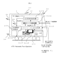
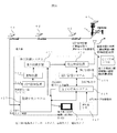
- FIG. 1 is a block diagram showing a schematic configuration of the train control system of the present invention.
- the train control system includes an on-board device 2 mounted on the train 1 and a ground device 3 installed on the ground.
- the on-board device 2 includes an on-board control system 21.
- the on-vehicle control system 21 includes an on-vehicle control device 211, an on-vehicle radio device 212, an on-vehicle monitoring device 5 attached to the train 1 (vehicle), and a monitoring device 2116 installed on the driver's seat 2117.
- the on-vehicle surveillance camera 5 and the device sensor 218 are provided at necessary locations outside and inside the train 1 (vehicle).
- the on-board surveillance device 5 includes a surveillance camera, a device sensor 218, and the like.
- the surveillance cameras include, for example, a front camera 51 that shoots the front of the train 1 traveling on the track 216, a rear camera 53 that shoots the rear of the train 1, a side camera 54 that shoots the surroundings and sides of the train 1, and a pantograph.
- the pantograph camera 52 for taking a picture, the door of the train 1 (vehicle), the in-vehicle camera 55 for taking a picture of the inside of the car, and the like are included.
- the equipment sensor 218 includes, for example, an overhead wire inspection sensor, a railway line equipment inspection sensor, a track inspection sensor, and the like.
- the on-board control device 211 controls the on-board device 2 by receiving a speed signal from the speed generator 214, a position signal from the on-board element 215, and the like.
- the on-board wireless device 212 is a device that wirelessly communicates data with the terrestrial wireless device 312. For example, a camera image (crossing image and crossing position) taken by the surveillance camera of the on-board monitoring device 5 and a device sensor.
- the sensor data detected by 218 is wirelessly transmitted from the antenna 213 to the terrestrial radio device 312 of the terrestrial device 3.
- the monitor device 2116 displays a camera image (railroad crossing image and railroad crossing position) and sensor data of a failure occurrence at a railroad crossing.
- a tour conductor such as a driver or a conductor can detect a failure occurrence situation on the ground side.
- the ground device 3 includes a ground control system 31.
- the ground control system 31 includes a ground control device 311, a ground radio device 312, a monitor device 314, an operation command device 320, and the like.
- the ground control device 311 receives, for example, the camera image of the ground surveillance camera 6 installed on the ground side and the sensor data of the device sensor 218 on the upper side of the vehicle, and outputs the sensor data to the ground radio device 312 and the monitor device 314.
- the surveillance camera of the ground surveillance device 6 includes, for example, a railway line camera 62 that photographs the railway line of the orbit 216, a railroad crossing camera 61 that photographs the inside of a railroad crossing, a home camera 63 that photographs a platform, and the like.
- the terrestrial radio device 312 transmits the camera image (crossing image and crossing position) taken by the surveillance camera of the terrestrial monitoring device 6 and the sensor data detected by the device sensor 218 from the antenna 313 to the on-board radio device 212 of the on-board device 2. Wirelessly transmit to.
- the monitoring device 314 is a camera image (railroad crossing image and railroad crossing position) taken by the surveillance camera of the ground surveillance device 6 and / or a camera image (railroad crossing image and railroad crossing position) taken by the surveillance camera of the on-board surveillance device 5. ) And the sensor data detected by various device sensors 218.
- the operation commander at the operation command center can confirm the failure occurrence status on the ground side, that is, the presence or absence of obstacles and obstacles, and can issue an operation command according to the result.
- FIG. 2 is a block diagram showing a configuration example of the on-board control device 211 in the on-board device 2.
- the on-vehicle control device 211 is a device that controls the control drive control device 2115 by transmitting and receiving a notch command, vehicle information, and the like to and from the control drive control device 2115 (brake control device) of the on-vehicle device 2.
- the on-board control device 211 includes a master controller (master controller: hereinafter referred to as a mass controller) 2111, an ATO device 2112, an operation mode switching device 2113, a vehicle information control device 2114, and a control drive control device 2115.
- master controller master controller: hereinafter referred to as a mass controller
- ATO Automatic Train Operation
- a security device Auto Train Control / ATC: Automatic Train Operation
- ATC device for departure control (opening and closing of the door after the train stops at the platform).
- scheduled operation control acceleration / deceleration of train, constant speed control, running control to the next station in a predetermined time
- fixed position stop control automatically move the train to a predetermined position on the platform
- It has a function to run from the start to the stop of the train by adding functions such as deceleration and stop control). For example, when the driver presses the start instruction button, the device automatically performs power running, constant speed or coasting, braking, and fixed point stop of the train.
- the mascon 2111 and the ATO device 2112 output a control drive command (notch command or torque command) including a control drive force based on the speed signal and the position signal, and the vehicle information (operation pattern) of the train 1 in the vehicle information control device 2114. , Timetable information), the output and speed of train 1 (vehicle) are controlled via the control drive control device 2115.
- the mascon 2111 is, for example, a switch device that manually performs power running, constant speed or coasting, braking, and stopping of train 1 when the driver operates the start button.
- the ATO device 2112 automatically performs power running, constant speed or coasting, braking, and stopping of the train 1 in response to an automatic operation command from the ATO central system 316 of the ground device 3.
- the operation mode switching device 2113 is a device that switches between the mascon 2111 and the ATO device 2112 in response to the operation mode switching command transmitted from the ground device 3, that is, switches the operation mode of the train 1 to the manual mode or the automatic mode.
- FIG. 3 is a block diagram showing a configuration example of the ground control system 31 in the ground device 3.
- the ground control system 31 includes a train detection device 318, an interlocking device 319, an operation management system 315, an ATO central system 316, a monitoring central system 317, the above-mentioned monitor device 314, and an operation command. It has an operation command device 320 and the like including a unit.
- the train detection device 318 outputs train detection information (fall / lift) indicating the position of each train when the train 1 approaches, for example, a preceding train (not shown).
- the interlocking device 319 turns the tumbler in a predetermined direction in response to a request for course setting, and if there is no other train (vehicle) on the course, the signal indicates the progress (green light) which means permission. , The safety of train operation in the station yard is guaranteed, and the train detection information detected by the train detection device 318 is output to the ground control device 311.
- the ground control device 311 calculates the stop limit position based on each information such as the train position received by the ground radio device 312, the stop limit position, the train detection of the interlocking device 319, and the traveling section stored inside, and the ground control device 311 calculates the stop limit position. It transmits to the on-board device 2 side via the antenna 313 of the wireless device 312.
- the terrestrial radio device 312 transmits and receives various information to and from the on-board device 2 via a radio base station (not shown).
- the operation management system 315 manages the operation of the train 1, automatically controls the course via the interlocking device of each station according to the planned operation schedule, and also has a means for acquiring information on the position of the train. It is a device that gives commands such as changing the evacuation order at the station when there is a disturbance.
- the ATO central system 316 operates in the presence of a security device (ATC device) in response to a command from the operation command unit of the operation command device 320 by the operation of the operation commander, and the departure control (train stops at the platform). After that, control until the train departs after opening and closing the door), scheduled operation control (control to accelerate / decelerate the train, control the constant speed, and run to the next station in a predetermined time), stop at a fixed position (at a predetermined position on the platform) It is a device that commands functions such as automatically decelerating and stopping a train, that is, a so-called train 1 running command from departure to stop.
- ATC device security device
- the surveillance central system 317 receives camera images from the surveillance camera of the ground surveillance device 6 and sensor data from various device sensors 218, and obstacles (including people, objects) that hinder the running of the train. , Vehicles, etc.) and obstacles (device failures) are monitored, and the results are output to the monitor device 314 and the terrestrial radio device 312, including an obstacle / obstacle detection device 3171 and a storage device 3172 that stores camera images and the like. It is a system.
- the commander of the operation command center on the ground side can judge the presence or absence of obstacles / obstacles from the camera image (railroad crossing image and railroad crossing position) and monitor data monitored by the monitor device 314, and the operation command (operation) according to the result. Mode, operation mode change, etc.) can be commanded to the ground side.
- the operation management system 315, the ATO central system 316, and the monitoring central system 317 are configured to operate in conjunction with each other. Further, the monitoring device 314, the operation management system 315, the ATO central system 316, the monitoring central system 317, and the operation command device 320 constitute an operation command system at the operation command center.
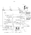
- FIG. 4 is a flowchart illustrating a processing procedure for notifying the upper side of the vehicle of the failure occurrence detection result and the failure occurrence status including the failure occurrence location when the failure occurrence is detected on the ground side in the train control system.
- Step S3111 The surveillance central system 317 receives a camera image taken by a surveillance camera installed in a place (railroad crossing) with poor visibility, and monitors obstacles and obstacles.
- Step S3112 The monitoring device 314 displays a camera image (railroad crossing image).
- Step S3113 In the operation command system on the ground side, for example, the operation commander may have obstacles (including people, objects, cars, etc.) or obstacles (including people, objects, cars, etc.) that hinder the running of the train 1 based on the monitor screen of the monitor device 314. Check the camera image (camera image) of the train that detected the device failure) and the obstacle detection result, and determine the presence or absence of obstacles or obstacles.
- the presence or absence of obstacles or obstacles may be automatically determined by the obstacle / obstacle detection device instead of the commander.
- Step S3114 When the ATO central system 316 determines that there is an obstacle at the railroad crossing, the camera image (railroad crossing image) and the railroad crossing position (railroad crossing ID) of the railroad crossing with the obstacle are transmitted to the upper side of the vehicle via the terrestrial radio device 312. It is transmitted to the on-board device 2.
- the camera image (railroad crossing image) and the railroad crossing position (railroad crossing ID) notify the on-board device of the ground site situation directly from a camera or sensor installed on the ground side or via the ground device. This notification is performed by a method of filtering the trains to be notified based on the position of each train or a method of simultaneously notifying one train in the vicinity.
- the train travels in front of the railroad crossing based on the train presence position information and the railroad crossing position information grasped by the ATO central system 316.
- the train 1 is specified, and the camera image and the railroad crossing position information are transmitted to the train 1 for the train 1.
- the information to be transmitted to the train may be a camera image (railroad crossing image) and a railroad crossing position (railroad crossing ID), but it is not always necessary to transmit the camera image as it is, and the judgment result of the presence or absence of obstacles and the information on the railroad crossing position are transmitted. You may.
- Step S3115 The ATO central system 316 also has obstacles depending on the train 1 (vehicle) and the railroad crossing position, that is, other trains 1'(vehicles) near the location of the obstacle, for example, the following train or the oncoming train.
- a camera image (railroad crossing image) and a railroad crossing position (railroad crossing ID) of a certain railroad crossing are transmitted via the terrestrial radio device 312.
- an obstacle or an image itself taken by the surveillance camera is transmitted to another train 1'via the ground device 3 or between trains without passing through the ground device. You may notify.
- Step S3116 The monitor device 2116 in the on-board device 2 on the upper side of the vehicle displays a camera image (railroad crossing image) and a railroad crossing position (railroad crossing ID) transmitted from the ground device 3 on the ground side. This allows the driver and tour operator to check the status of failure at the railroad crossing.
- an obstacle is detected, displayed, and determined on the upper side of the vehicle, and the train 1 is controlled in response to the obstacle.
- FIGS. 5 to 7 only the configurations and steps changed from the first embodiment are shown below.
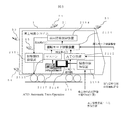
- FIG. 5 is a block diagram showing a configuration example of the on-vehicle control system of the second embodiment.
- the on-board control system 21 further includes an obstacle detection device 2118.
- the obstacle detection device 2118 receives the railroad crossing image and the railroad crossing ID (position) on the ground side and outputs them to the monitoring device 2116.
- the monitoring device 2116 displays and monitors the railroad crossing image and the railroad crossing ID (position). As a result, obstacles can be detected on the upper side of the vehicle.
- FIG. 6 is a block diagram showing a configuration example of the ground control system in the ground device of the second embodiment.
- the monitoring central system 317 can omit the obstacle / obstacle detection device 3171.
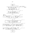
- FIG. 7 is a flowchart illustrating a processing procedure for detecting and displaying the occurrence of a failure on the upper side of the vehicle in the train control system of the second embodiment.
- Step S4111 The obstacle detection device 2118 of the on-board control system 21 receives a camera image taken by a surveillance camera installed in a place (railroad crossing) with poor visibility, and monitors obstacles and obstacles.
- Step S4112 When the on-board control system 21 determines that there is an obstacle at the railroad crossing by the obstacle detection device 2118, the vehicle displays a camera image (railroad crossing image) and a railroad crossing position (railroad crossing ID) showing the railroad crossing with the obstacle. It is transmitted to the ground device 3 on the ground side via the upper radio device 212.
- Step S4113 The on-board control system 21 also has obstacles depending on the train 1 (vehicle) and the railroad crossing position, that is, the other train 1'(vehicle) near the place where the obstacle occurs, for example, the following train or the oncoming train.
- a camera image (railroad crossing image) and a railroad crossing position (railroad crossing ID) showing a certain railroad crossing are transmitted via the on-board radio device 212.
- the obstacle detection device 2118 of the on-board control system 21 is, for example, an obstacle (including people, objects, cars, etc.) that obstructs the operation commander in traveling on the train 1 based on the monitor screen of the monitor device 314. ), The camera image (camera image) of the train that detected the occurrence of the obstacle (device failure) and the obstacle detection result are confirmed, and the presence or absence of the obstacle or the obstacle is judged.
- the presence or absence of obstacles or obstacles may be automatically determined by the obstacle / obstacle detection device instead of the commander.
- Step S4115 The monitor device 2116 in the on-board control system 21 on the upper side of the vehicle displays a camera image (railroad crossing image) and a railroad crossing position (railroad crossing ID) received by the obstacle detection device 2118. This allows the driver and tour operator to check the status of failure at the railroad crossing.
- the operation commander in the operation command system on the ground side determines the presence or absence of obstacles. For example, in the monitoring central system 317, image recognition technology and AI (artificial intelligence: population) are performed. It may be done automatically using intelligence) technology. In this case, the operation commander becomes unnecessary.
- image recognition technology and AI artificial intelligence: population
- the present invention is not limited to the above-described embodiment, and includes various modifications.
- the above-described examples have been described in detail in order to explain the present invention in an easy-to-understand manner, and are not necessarily limited to those having all the described configurations.
Landscapes
- Engineering & Computer Science (AREA)
- Mechanical Engineering (AREA)
- Multimedia (AREA)
- Signal Processing (AREA)
- Life Sciences & Earth Sciences (AREA)
- Sustainable Development (AREA)
- Sustainable Energy (AREA)
- Power Engineering (AREA)
- Transportation (AREA)
- Train Traffic Observation, Control, And Security (AREA)
- Electric Propulsion And Braking For Vehicles (AREA)
- Closed-Circuit Television Systems (AREA)
Abstract
列車が走行する軌道の沿線周辺、特に、運転士から見通しのきかない場所に設置された監視カメラやセンサで得られるカメラ映像やセンサデータをもとに地上側に障害物や支障があることを検知できた場合、障害物や支障を撮影した監視カメラのカメラ映像と位置(位置ID)を車上側に送信、表示する技術を提供する。 地上装置は、見通しの悪い場所(カーブ、ホーム、踏切等)に設置された監視カメラのカメラ映像(画像)を地上装置側にて収集し、収集したカメラ映像(画像)を位置情報(位置ID)とともに車上装置へ送信し、車上装置は、地上装置より送信されたカメラ映像および位置情報を受信、表示する。
Description
本発明は列車制御システムに関する。
従来、列車の運転を支援する技術として、例えば、特開2017-87978号公報(特許文献1)に記載の技術がある。この公報には、「線路を走行する列車に搭載された車上装置と、前記線路に設けられた踏切内を撮像して画像情報を生成する撮像装置と、前記画像情報又はこれに基づく情報を踏切内情報として前記車上装置に無線送信する地上装置と、前記列車の運転室に設けられ、前記列車が前記踏切手前の所定位置に到達すると、前記車上装置が前記地上装置から受信した前記踏切内情報を表示する表示装置と、を含む、列車運転支援システム」により、特に踏切通過時の前記運転士の負担を軽減して列車の運転を支援する発明が開示されている。
特許文献1は、列車が踏切手前の位置に到達したとき、撮像装置にて撮影した踏切内情報(画像)を地上装置にて収集する。そして、収集した踏切内情報を地上装置から車上装置に送信し、車上装置の表示装置に表示し、この表示により運転士が踏切内の状況を確認できるようにしたものである。しかし、特許文献1では、撮像装置にて撮影した画像から列車が走行する上で障害となる障害物や車上の各種装置の故障を検知した場合、障害物や支障の有無に応じて列車の制御を地上から遠隔制御を一元管理することについては想定されていない。そのため、特許文献1の発明は、運転士が車上において、踏切内情報(画像)を表示・確認できるという効果に留まる。
また、従来は、運転士から見通しの効かない場所を通過する場合には、運転士が警笛を鳴らすなどして、列車通過を周囲に知らせているのが実情である。仮に、運転士が踏切内の状況を画像にて表示・確認できるとしても、画像情報だけでは、運転士が確実に障害物や支障有無を検知することは難しい。さらに、踏み切り以外の見通しが悪いカーブや駅ホームなどの場所における状況については、運転士に情報を与える手段は考慮されていない。
そこで、本発明では、列車が走行する軌道の沿線周辺、特に、運転士から見通しの効かない場所、例えば、カーブや、踏切、駅ホームなどに監視カメラやセンサ(ミリ波やLIDARなど)を設置し、監視カメラやセンサで得られるカメラ映像(又はカメラ画像)をもとに地上側で障害物や支障があることを検知し、かつ、障害物や支障が検知できた場合、障害物や支障を撮影した監視カメラのカメラ映像(もしくは障害検知結果)と位置(設備ID)を車上側に送信し、車上側にて監視カメラの画像や位置情報を表示・確認し得る技術を提供することを目的とする。
上記課題を解決するために、本発明の代表的な本発明の列車制御システムの一つは、
地上及び/又は車上に設置され、列車が走行する軌道の周辺や沿線上を撮影する監視カメラと、地上装置と、車上装置を備え、
前記地上装置は、
前記監視カメラにて撮影したカメラ映像を収集し、収集したカメラ映像をもとに障害物の有無を検知する障害物検知装置と、
前記障害物検知装置にて障害物を検知した場合、障害物を検知した監視カメラのカメラ映像と障害物検知結果の少なくともいずれかの情報、及び障害物を検知した監視カメラの場所を示す位置情報を車上装置に送信する地上無線装置とを、有し、
前記車上装置は、
前記地上装置の地上無線装置から送信されたカメラ映像と障害物検知結果の少なくともいずれかの情報及び障害物を検知した監視カメラの前記位置情報を受信する車上無線装置と、
前記車上無線装置にて受信したカメラ映像と障害物検知結果の少なくともいずれかの情報と障害発生場所を示す位置情報を表示するモニタ装置と、有し、
前記列車が障害・支障発生場所に接近する前に現場状況を前記モニタ装置で確認可能とする
ことを特徴とする。
また、地上装置は、さらに
列車(車両)と位置情報に応じて、近くに別の列車(車両)がいる場合には、監視カメラ映像と位置情報を近くの別列車(車両)の車上装置に送信し、後続列車や対向列車に注意喚起を促す。
列車(車両)と位置情報に応じて、近くに別の列車(車両)がいる場合には、監視カメラ映像と位置情報を近くの別列車(車両)の車上装置に送信し、後続列車や対向列車に注意喚起を促す。
上記課題を解決するために、本発明の代表的な本発明の列車制御システムの他の一つは、地上及び/又は車上に設置され、列車が走行する軌道の周辺や沿線上を撮影する監視カメラと、地上装置と、車上装置を備え、
前記地上装置は、
監視カメラにて撮影したカメラ映像及び監視カメラの場所を示す位置情報を車上装置に送信する地上無線装置とを、有し、
前記車上装置は、
前記地上装置の地上無線装置から送信されたカメラ映像と障害物を検知した監視カメラの前記位置情報を受信する車上無線装置と、
前記地上装置の地上無線装置から送信されたカメラ映像をもとに障害物の有無を検知する障害物検知装置と、
前記障害物検知装置にて障害物を検知した場合、障害物を検知したカメラ映像と障害物検知結果の少なくともいずれかの情報、及び前記地上無線装置から送信された監視カメラの場所を示す位置情報を表示するモニタ装置と、有し、
前記列車が障害・支障発生場所に接近する前に現場状況を前記モニタ装置で確認可能とする
ことを特徴とする。
本発明によれば、地上側における障害物に関する情報を車上の運転士に情報提供することができる。
例えば、列車側の運転士などにおいて、列車走行上、地上側における障害や支障となる物体、例えば、踏切遮断後の人や車、動物などの侵入や留まり、踏切遮断機(踏切から直接信号をとる、又は特殊信号発光機の点灯状況など)、非常押しボタン状況(ボタンから直接信号をとる、又は特殊信号発光機の点灯状況など)、駅ホームでの落下、ふらつき、駅ホームの混雑などを的確に、かつ、迅速に確認でき、より安全な運転管理が可能である。
上記した以外の課題、構成及び効果は、以下の実施形態の説明により明らかにされる。
上記した以外の課題、構成及び効果は、以下の実施形態の説明により明らかにされる。
以下、実施例について図面を用いて説明する。
まず、以下の実施例において、地上側で発生した障害や支障を検知した場合とは、軌道上にある踏切、軌道周辺の駅ホームや運転士にとって見通しが効かない、つまり、沿線上で見通しが悪い場所、例えば、軌道のカーブや駅ホームなどに設置した監視カメラやセンサで障害や支障などを検知した場合を指す。障害や支障発生の検知は、地上側で行っても車上側で行っても良い。
以下、踏切における障害物を監視カメラで撮影した例について説明する。
まず、以下の実施例において、地上側で発生した障害や支障を検知した場合とは、軌道上にある踏切、軌道周辺の駅ホームや運転士にとって見通しが効かない、つまり、沿線上で見通しが悪い場所、例えば、軌道のカーブや駅ホームなどに設置した監視カメラやセンサで障害や支障などを検知した場合を指す。障害や支障発生の検知は、地上側で行っても車上側で行っても良い。
以下、踏切における障害物を監視カメラで撮影した例について説明する。
図1は、本発明の列車制御システムの概略構成を示すブロック図である。
列車制御システムは、列車1に搭載された車上装置2、地上に設置された地上装置3を有する。
列車制御システムは、列車1に搭載された車上装置2、地上に設置された地上装置3を有する。
車上装置2は、車上制御システム21を備えている。車上制御システム21は、車上制御装置211、車上無線装置212、列車1(車両)に取り付けられた車上用監視デバイス5、運転席2117に設置されたモニタ装置2116を有する。車上用監視カメラ5及び機器センサ218は、列車1(車両)の車外及び車内の必要な個所に設けられる。
車上用監視デバイス5は、監視カメラや機器センサ218などを含む。
監視カメラは、例えば、軌道216を走行する列車1の前方を撮影する前方カメラ51、列車1の後方を撮影する後方カメラ53、列車1の周囲や側方を撮影する側方カメラ54、パンタグラフを撮影するパンタカメラ52、列車1(車両)のドアや車内を撮影する車両内カメラ55などを含む。
機器センサ218は、例えば、架線検測センサ、沿線機器検測センサ、軌道検測センサなどを含む。
機器センサ218は、例えば、架線検測センサ、沿線機器検測センサ、軌道検測センサなどを含む。
車上制御装置211は、速度発電機214からの速度信号、車上子215からの位置信号などを受けて車上装置2を制御する。
車上無線装置212は、地上無線装置312との間でデータを無線通信する装置であり、例えば、車上用監視デバイス5の監視カメラで撮影したカメラ映像(踏切画像及び踏切位置)や機器センサ218にて検知したセンサデータをアンテナ213から地上装置3の地上無線装置312に無線送信する。
モニタ装置2116は、踏切における障害発生をカメラで撮影したカメラ映像(踏切画像及び踏切位置)やセンサデータを表示する。これにより、運転者や車掌などの添乗員は、地上側における障害発生状況を検知することができる。
地上装置3は、地上制御システム31を備えている。地上制御システム31は、地上制御装置311、地上無線装置312、モニタ装置314、運転指令装置320などを有する。
地上制御装置311は、例えば、地上側に設置された地上用監視カメラ6のカメラ画像や車上側の機器センサ218のセンサデータを受信し、地上無線装置312及びモニタ装置314に出力する。
地上用監視デバイス6の監視カメラは、例えば、軌道216の沿線を撮影する沿線カメラ62、踏切内を撮影する踏切カメラ61、プラットホームを撮影するホームカメラ63などを含む。
地上無線装置312は、地上用監視デバイス6の監視カメラにて撮影したカメラ映像(踏切画像及び踏切位置)や機器センサ218で検知したセンサデータをアンテナ313から車上装置2の車上無線装置212に無線送信する。
モニタ装置314は、地上用監視デバイス6の監視カメラにて撮影したカメラ映像(踏切画像及び踏切位置)及び/又は車上用監視デバイス5の監視カメラにて撮影したカメラ映像(踏切画像及び踏切位置)や各種の機器センサ218にて検出したセンサデータを表示する。これにより、運転指令所における運転指令員は、地上側における障害発生状況、つまり、障害物や支障の有無を確認することができ、また、その結果に応じた運転指令を行うことができる。
図2は、車上装置2における車上制御装置211の構成例を示すブロック図である。
車上制御装置211は、車上装置2の制駆動制御装置2115(ブレーキ制御装置)との間でノッチ指令や車両情報等を送受信し、制駆動制御装置2115を制御する装置である。
車上制御装置211は、車上装置2の制駆動制御装置2115(ブレーキ制御装置)との間でノッチ指令や車両情報等を送受信し、制駆動制御装置2115を制御する装置である。
車上制御装置211は、主幹制御器(マスタコントローラ:以下、マスコンと称する)2111、ATO装置2112、運転モード切替装置2113と、車両情報制御装置2114、制駆動制御装置2115を有する。
ATO(Automatic Train Operation)とは、保安装置(自動列車制御装置/ATC:Automatic Train Operation)の存在の下で動作し、ATC装置を基本にして発車制御(列車がホームに停止後、ドアの開閉を経て発車するまでの制御)、定時運転制御(列車の加減速、定速制御を行い、所定の時間で次駅まで走行制御)、定位置停止制御(ホームの所定位置に列車を自動的に減速、停止させる制御)などの機能を追加し、列車の出発から停止までの走行を行う機能を有する。例えば、運転者がスタート指示ボタンを押すと、列車の力行、定速または惰行、制動、定点停止を自動的に行う装置である。
マスコン2111及びATO装置2112は、速度信号及び位置信号をもとに制駆動力を含む制駆動指令(ノッチ指令やトルク指令)を出力し、車両情報制御装置2114における列車1の車両情報(運用パターン、ダイヤ情報)をもとに制駆動制御装置2115を介して列車1(車両)の出力・速度を制御する。
また、マスコン2111は、例えば、運転士がスタートボタンを操作すると、列車1の力行、定速または惰行、制動、停止を手動的に行うスイッチ装置である。
ATO装置2112は、地上装置3のATO中央システム316からの自動運転指令を受けて列車1の力行、定速または惰行、制動、停止を自動的に行う。
運転モード切替装置2113は、地上装置3から送信される運転モード切替指令を受けてマスコン2111とATO装置2112を切り替える、つまり、列車1の運転モードを手動モード又は自動モードに切り替える装置である。
図3は、地上装置3における地上制御システム31の構成例を示すブロック図である。
地上制御システム31は、地上制御装置311、地上無線装置312の他に列車検知装置318、連動装置319、運行管理システム315、ATO中央システム316、監視中央システム317、上述したモニタ装置314、運転指令部を含む運転指令装置320などを有する。
地上制御システム31は、地上制御装置311、地上無線装置312の他に列車検知装置318、連動装置319、運行管理システム315、ATO中央システム316、監視中央システム317、上述したモニタ装置314、運転指令部を含む運転指令装置320などを有する。
列車検知装置318は、列車1が、例えば、先行する列車(図示せず)に近づいた場合、それぞれの列車の位置を示す列車検知情報(落下/扛上)を出力する。
連動装置319は、進路設定の要求によって転てつ器を所定の方向に転換し、進路上に他の列車(車両)が存在しなければ、信号機に許可を意味する進行(青信号)を現示し、駅構内の列車運転の安全を保障するものであり、列車検知装置318にて検出した列車検知情報を地上制御装置311に出力する。
地上制御装置311は、地上無線装置312にて受信した列車位置、停止限界位置及び連動装置319の列車検知や内部に記憶した走行区間などの各情報をもとに停止限界位置を算出し、地上無線装置312のアンテナ313を介して車上装置2側に送信する。
地上無線装置312は、無線基地局(図示せず)を介して車上装置2との間で各種情報を送受信する。
運行管理システム315は、列車1の運行を管理するものであり、計画運行ダイヤに従って自動的に各駅の連動装置経由で進路を制御するほか、列車の在線位置の情報を取得する手段を備え、運行乱れがあった場合には、駅での退避順序の変更などの指令を行う装置である。
ATO中央システム316は、運転指令員の操作にて、運転指令装置320の運転指令部からの指令を受けて保安装置(ATC装置)の存在の下で動作し、発車制御(列車がホームに停止後、ドアの開閉を経て発車するまでの制御)、定時運転制御(列車の加減速、定速制御を行い、所定の時間で次駅まで走行する制御)、定位置停止(ホームの所定位置に列車を自動的に減速、停止させる制御)などの機能を指令する、いわゆる列車1の出発から停止までの走行の指令を行う装置である。
監視中央システム317は、例えば、地上用監視デバイス6の監視カメラからのカメラ画像や各種の機器センサ218からのセンサデータを受信し、列車を走行する上で障害となる障害物(含人、物、車等)や支障発生(装置故障)の有無を監視し、その結果をモニタ装置314及び地上無線装置312に出力する障害物・支障検知装置3171やカメラ映像などを記憶する記憶装置3172を含むシステムである。
地上側の運転指令所の指令員は、モニタ装置314にモニタされるカメラ映像(踏切画像及び踏切位置)やモニタデータにより、障害物・支障有無を判断でき、その結果に応じた運転指令(運転モードや運転モード変更など)を地上側に指令することができる。
運行管理システム315、ATO中央システム316、監視中央システム317は、連動して動作するように構成する。また、モニタ装置314、運行管理システム315、ATO中央システム316、監視中央システム317、運転指令装置320は、運転指令所における運転指令システムを構成している。
図4は、列車制御システムにおいて、地上側で障害発生を検知した場合、障害発生検知結果と障害発生場所を含む障害発生状況を車上側に通知する処理手順を説明するフローチャートである。
図4のフローチャートに基づく動作は以下のとおりである。
ステップS3111:
監視中央システム317は、見通しの悪い場所(踏切)に設置された監視カメラにて撮影したカメラ画像を受信し、障害物や支障を監視する。
ステップS3111:
監視中央システム317は、見通しの悪い場所(踏切)に設置された監視カメラにて撮影したカメラ画像を受信し、障害物や支障を監視する。
ステップS3112:
モニタ装置314は、カメラ画像(踏切画像)を表示する。
モニタ装置314は、カメラ画像(踏切画像)を表示する。
ステップS3113:
地上側の運転指令システムにおいて、例えば、運転指令員は、モニタ装置314のモニタ画面をもとに列車1を走行する上で障害となる障害物(含人、物、車等)や支障発生(装置故障)を検知した列車のカメラ映像(カメラ画像)や支障検知結果を確認し、障害物や支障の有無を判断する。
ここで、障害物や支障の有無の判断は、指令員ではなく障害物・支障検知装置にて自動的に判断されるようにしても良い。
地上側の運転指令システムにおいて、例えば、運転指令員は、モニタ装置314のモニタ画面をもとに列車1を走行する上で障害となる障害物(含人、物、車等)や支障発生(装置故障)を検知した列車のカメラ映像(カメラ画像)や支障検知結果を確認し、障害物や支障の有無を判断する。
ここで、障害物や支障の有無の判断は、指令員ではなく障害物・支障検知装置にて自動的に判断されるようにしても良い。
ステップS3114:
ATO中央システム316は、踏切に障害物があると判断した場合、障害物がある踏切を写したカメラ画像(踏切画像)と踏切位置(踏切ID)を、地上無線装置312を介して車上側の車上装置2に送信する。
このカメラ画像(踏切画像)と踏切位置(踏切ID)は、地上側に設置したカメラやセンサなどから直接、又は地上装置を介して地上現場状況を車上装置に通知する。この通知は、各列車の位置をもとに、通知対象とする列車をフィルタする方法や周辺の一体の列車に一斉に報知する方法で行う。
ここで、地上装置を介して地上現場状況を車上装置に通知する場合、ATO中央システム316で、把握している列車の在線位置の情報と踏切位置の情報に基づいて、踏切手前を走行する列車1を特定して、当該列車1に対してカメラ画像と踏切位置の情報を列車1へ送信する。列車へ送信する情報は、カメラ画像(踏切画像)と踏切位置(踏切ID)としても良いが、必ずしもカメラ画像をそのまま送信する必要はなく、障害物有無の判断結果と踏切位置の情報を送信しても良い。
ステップS3115:
ATO中央システム316は、列車1(車両)と踏切位置に応じて、つまり、障害発生場所に近い他の列車1’(車両)、例えば、後続列車や対向列車に対しても同様に障害物がある踏切を写したカメラ画像(踏切画像)と踏切位置(踏切ID)を、地上無線装置312を介して送信する。
ここで、列車1が走行中に前記監視カメラで撮影した障害物または画像そのものを前記地上装置3を経由して、または前記地上装置を経由せず列車間で他の列車1’に送信し、通知しても良い。
ATO中央システム316は、列車1(車両)と踏切位置に応じて、つまり、障害発生場所に近い他の列車1’(車両)、例えば、後続列車や対向列車に対しても同様に障害物がある踏切を写したカメラ画像(踏切画像)と踏切位置(踏切ID)を、地上無線装置312を介して送信する。
ここで、列車1が走行中に前記監視カメラで撮影した障害物または画像そのものを前記地上装置3を経由して、または前記地上装置を経由せず列車間で他の列車1’に送信し、通知しても良い。
ステップS3116:
車上側の車上装置2におけるモニタ装置2116は、地上側の地上装置3から送信されたカメラ画像(踏切画像)と踏切位置(踏切ID)を表示する。これにより、運転士や添乗員は、踏切に障害発生状況を確認することができる。
車上側の車上装置2におけるモニタ装置2116は、地上側の地上装置3から送信されたカメラ画像(踏切画像)と踏切位置(踏切ID)を表示する。これにより、運転士や添乗員は、踏切に障害発生状況を確認することができる。
本実施例は、車上側で障害物を検知、表示、判断し、かつ、障害物に対応して列車1を制御するものである。
図5~図7を参照し、実施例1から変更がある構成、ステップのみ、以下に示す。
図5~図7を参照し、実施例1から変更がある構成、ステップのみ、以下に示す。
図5は、実施例2の車上制御システムの構成例を示すブロック図である。車上制御システム21は、さらに、障害物検知装置2118を有する。
障害物検知装置2118は、地上側の踏切画像及び踏切ID(位置)を受信し、モニタ装置2116に出力する。モニタ装置2116は、踏切画像及び踏切ID(位置)を表示し、モニタする。これにより、車上側で障害物を検知することができる。
障害物検知装置2118は、地上側の踏切画像及び踏切ID(位置)を受信し、モニタ装置2116に出力する。モニタ装置2116は、踏切画像及び踏切ID(位置)を表示し、モニタする。これにより、車上側で障害物を検知することができる。
図6は、実施例2の地上装置における地上制御システムの構成例を示すブロック図である。障害物を車上側で検知する場合は、監視中央システム317は、障害物・支障検知装置3171を省略することができる。
図7は、実施例2の列車制御システムにおいて、車上側で障害発生を検知し、表示する処理手順を説明するフローチャート。
ステップS4111:
車上制御システム21の障害物検知装置2118は、見通しの悪い場所(踏切)に設置された監視カメラにて撮影したカメラ画像を受信し、障害物や支障を監視する。
車上制御システム21の障害物検知装置2118は、見通しの悪い場所(踏切)に設置された監視カメラにて撮影したカメラ画像を受信し、障害物や支障を監視する。
ステップS4112:
車上制御システム21は、障害物検知装置2118にて、踏切に障害物があると判断した場合、障害物がある踏切を写したカメラ画像(踏切画像)と踏切位置(踏切ID)を、車上無線装置212を介して地上側の地上装置3に送信する。
車上制御システム21は、障害物検知装置2118にて、踏切に障害物があると判断した場合、障害物がある踏切を写したカメラ画像(踏切画像)と踏切位置(踏切ID)を、車上無線装置212を介して地上側の地上装置3に送信する。
ステップS4113:
車上制御システム21は、列車1(車両)と踏切位置に応じて、つまり、障害発生場所に近い他の列車1’(車両)、例えば、後続列車や対向列車に対しても同様に障害物がある踏切を写したカメラ画像(踏切画像)と踏切位置(踏切ID)を、車上無線装置212を介して送信する。
車上制御システム21は、列車1(車両)と踏切位置に応じて、つまり、障害発生場所に近い他の列車1’(車両)、例えば、後続列車や対向列車に対しても同様に障害物がある踏切を写したカメラ画像(踏切画像)と踏切位置(踏切ID)を、車上無線装置212を介して送信する。
ステップS4114:
車上制御システム21の障害物検知装置2118は、例えば、運転指令員は、モニタ装置314のモニタ画面をもとに列車1を走行する上で障害となる障害物(含人、物、車等)や支障発生(装置故障)を検知した列車のカメラ映像(カメラ画像)や支障検知結果を確認し、障害物や支障の有無を判断する。ここで、障害物や支障の有無の判断は、指令員ではなく障害物・支障検知装置にて自動的に判断されるようにしても良い。
ステップS4115:
車上側の車上制御システム21におけるモニタ装置2116は、障害物検知装置2118にて受信したカメラ画像(踏切画像)と踏切位置(踏切ID)を表示する。これにより、運転士や添乗員は、踏切に障害発生状況を確認することができる。
車上側の車上制御システム21におけるモニタ装置2116は、障害物検知装置2118にて受信したカメラ画像(踏切画像)と踏切位置(踏切ID)を表示する。これにより、運転士や添乗員は、踏切に障害発生状況を確認することができる。
以上述べた本実施例では、障害物・支障有無の判断を地上側の運転指令システムにおける運転指令員が行っているが、例えば、監視中央システム317において、画像認識技術やAI(artificial intelligence:人口知能)技術を利用して自動的に行うようにしても良い。この場合、運転指令員が不要になる。
なお、本発明は上述した実施例に限定されるものではなく、様々な変形例が含まれる。例えば、上述した実施例は本発明を分かりやすく説明するために詳細に説明したものであり、必ずしも説明した全ての構成を備えるものに限定されるものではない。
1 列車(車両)
2 車上装置
21 車上制御システム
211 車上制御装置
212 車上無線装置
2111 マスコン
2112 ATO装置
2113 運転モード切替装置
2114 車両情報制御装置
2115 制駆動制御装置
3 地上装置
31 地上制御システム
311 地上制御装置
312 地上無線装置
314 モニタ装置
315 運行管理システム
316 ATO中央システム
317 監視中央システム
3171 障害物・支障検知装置
318 列車検知装置
319 連動装置
320 運転指令装置
5 車上用監視デバイス
6 地上用監視デバイス
2 車上装置
21 車上制御システム
211 車上制御装置
212 車上無線装置
2111 マスコン
2112 ATO装置
2113 運転モード切替装置
2114 車両情報制御装置
2115 制駆動制御装置
3 地上装置
31 地上制御システム
311 地上制御装置
312 地上無線装置
314 モニタ装置
315 運行管理システム
316 ATO中央システム
317 監視中央システム
3171 障害物・支障検知装置
318 列車検知装置
319 連動装置
320 運転指令装置
5 車上用監視デバイス
6 地上用監視デバイス
Claims (11)
- 列車制御システムにおいて、
地上及び/又は車上に設置され、列車が走行する軌道の周辺や沿線上を撮影する監視カメラと、地上装置と、車上装置を備え、
前記地上装置は、
前記監視カメラにて撮影したカメラ映像を収集し、収集したカメラ映像をもとに障害物・支障の有無を検知する障害物検知装置と、
前記障害物検知装置にて障害物・支障を検知した場合、障害物・支障を検知した監視カメラのカメラ映像と障害物・支障検知結果の少なくともいずれかの情報、及び障害・支障発生場所を示す位置情報を車上装置に送信する地上無線装置とを、有し、
前記車上装置は、
前記地上装置の地上無線装置から送信されたカメラ映像と障害物・支障検知結果の少なくともいずれかの情報、及び障害・支障発生場所を示す位置情報を受信する車上無線装置と、
前記車上無線装置にて受信したカメラ映像と障害物・支障検知結果の少なくともいずれかの情報、及び障害・支障発生場所を示す位置情報を表示するモニタ装置とを、有し、
前記列車が障害・支障発生場所に接近する前に現場状況を前記モニタ装置で確認可能とする
ことを特徴とする列車制御システム。 - 請求項1に記載された列車制御システムにおいて、
前記監視カメラは、地上に設置され、軌道の沿線を撮影する沿線カメラ、踏切内を撮影する踏切カメラ、プラットホームを撮影するホームカメラの1つ以上、及び/または車上に設置され、軌道を走行する列車の前方を撮影する前方カメラ、列車の後方を撮影する後方カメラ、列車の周囲や側方を撮影する側方カメラ、パンタグラフを撮影するパンタカメラ、列車のドアや車内を撮影する車両内カメラ、の1つ以上を含む
ことを特徴とする列車制御システム。 - 請求項1又は2に記載された列車制御システムにおいて、
前記車上が走行中に前記監視カメラで撮影した障害物または画像そのものを前記地上装置を経由して、または前記地上装置を経由せず列車間で他の列車に送信し、通知する
ことを特徴とする列車制御システム。 - 地上及び/又は車上に設置され、列車が走行する軌道の周辺や沿線上を撮影する監視カメラと、地上装置と、車上装置を備え、
前記地上装置は、
監視カメラにて撮影したカメラ映像及び監視カメラの場所を示す位置情報を車上装置に送信する地上無線装置と、を有し、
前記車上装置は、
前記地上装置の地上無線装置から送信されたカメラ映像と障害物を検知した監視カメラの前記位置情報を受信する車上無線装置と、
前記地上装置の地上無線装置から送信されたカメラ映像をもとに障害物の有無を検知する障害物検知装置と、
前記障害物検知装置にて障害物を検知した場合、障害物を検知したカメラ映像と障害物検知結果の少なくともいずれかの情報、及び前記地上無線装置から送信された監視カメラの場所を示す位置情報を表示するモニタ装置と、有し、
前記列車が障害・支障発生場所に接近する前に現場状況を前記モニタ装置で確認可能とする
ことを特徴とする列車制御システム。 - 請求項1又は4に記載された列車制御システムにおいて、
前記地上装置は、さらに
列車と位置情報に応じて、近くに別の列車がいる場合には、監視カメラ映像と位置情報を近くの別列車の車上装置に送信し、後続列車や対向列車に注意喚起を促す
ことを特徴とする列車制御システム。 - 請求項1又は5に記載された列車制御システムにおいて、
前記地上装置は、さらに、
前記監視カメラにて撮影したカメラ映像を表示するモニタ装置を含み、
前記列車が障害・支障発生場所に接近する前に現場状況を前記モニタ装置で確認可能とする
ことを特徴とする列車制御システム。 - 請求項1~6の何れか一項に記載された列車制御システムにおいて、
前記監視カメラは、沿線カメラ、踏切カメラ、ホームカメラの一つ以上を含む
ことを特徴とする列車制御システム。 - 列車制御システムにおいて、
地上に設置され、列車が走行する上で障害・支障となる障害物を撮影し、カメラ映像を出力する監視カメラと、
前記監視カメラにて撮影したカメラ映像と障害発生場所を示す位置情報を受信し、表示するモニタ装置を含む地上装置と、
前記地上装置から送信されるカメラ映像と障害発生場所を示す位置情報を受信し、表示するモニタ装置を含む車上装置と、を備え、
地上装置は、前記監視カメラが撮影したカメラ映像をもとに列車走行の障害・支障となり得る障害物・支障を検知した場合、前記カメラ映像と障害発生場所を示す位置を示す情報を障害発生場所に近くの列車の車上装置に送信し、
車上装置は、地上装置から送信されたカメラ映像と障害発生場所を示す位置情報をモニタ装置にて表示し、
前記列車が障害・支障発生場所に接近する前に現場状況を前記モニタ装置で確認可能とする
ことを特徴とする列車制御システム。 - 請求項8に記載された列車制御システムにおいて、
前記監視カメラは、沿線カメラ、踏切カメラ、ホームカメラの一つ以上を含む、
ことを特徴とする列車制御システム。 - 請求項8に記載された列車制御システムにおいて、
前記監視カメラは、
地上に設置され、運転席から見通しのきかない場所を撮影し、運転席から見通しのきかない場所を撮影したカメラ映像と障害発生場所を示す位置を示す情報を出力し、
前記地上装置は、
前記監視カメラが撮影したカメラ映像と障害発生場所を示す位置情報を受信、表示するモニタ装置と、
前記カメラ映像から障害物有無を判断する機能を有する障害物検知装置と、
前記監視カメラのカメラ映像と位置を示す情報を車上無線装置へ送信する地上無線装置と、を含み、
前記車上装置は、
前記車上無線装置にて受信した監視カメラのカメラ映像と位置を示す情報を表示する車上モニタ装置と、
前記地上装置から送信された監視カメラのカメラ映像と位置を示す情報を受信する車上無線装置と、を含み、
前記地上装置は、
前記障害物検知装置にて障害物を検知した場合、当該障害物を検知した監視カメラのカメラ映像と位置を示す情報を、前記地上無線装置を介して障害物に近い場所に在線する列車に送信し、
前記車上装置は、前記地上装置から送信された障害物を検知した監視カメラのカメラ映像と位置を示す情報を表示し、
前記列車が障害・支障発生場所に接近する前に現場状況を前記モニタ装置で確認可能とする
ことを特徴とする列車制御システム。 - 請求項10に記載された列車制御システムにおいて、
運転席から見通しのきかない場所が、カーブ、踏切、ドア付近の何れか1つ以上であり、
前記監視カメラが、沿線カメラ、踏切カメラ、ホームカメラの何れか1つ以上である
ことを特徴とする列車制御システム。
Priority Applications (1)
| Application Number | Priority Date | Filing Date | Title |
|---|---|---|---|
| EP20864310.6A EP4032782A4 (en) | 2019-09-17 | 2020-04-16 | TRAIN CONTROL SYSTEM |
Applications Claiming Priority (2)
| Application Number | Priority Date | Filing Date | Title |
|---|---|---|---|
| JP2019168111A JP7153000B2 (ja) | 2019-09-17 | 2019-09-17 | 列車制御システム |
| JP2019-168111 | 2019-09-17 |
Publications (1)
| Publication Number | Publication Date |
|---|---|
| WO2021053866A1 true WO2021053866A1 (ja) | 2021-03-25 |
Family
ID=74877438
Family Applications (1)
| Application Number | Title | Priority Date | Filing Date |
|---|---|---|---|
| PCT/JP2020/016712 Ceased WO2021053866A1 (ja) | 2019-09-17 | 2020-04-16 | 列車制御システム |
Country Status (3)
| Country | Link |
|---|---|
| EP (1) | EP4032782A4 (ja) |
| JP (1) | JP7153000B2 (ja) |
| WO (1) | WO2021053866A1 (ja) |
Cited By (6)
| Publication number | Priority date | Publication date | Assignee | Title |
|---|---|---|---|---|
| CN113581252A (zh) * | 2021-07-21 | 2021-11-02 | 南京苏莱瑞新技术有限公司 | 一种基于多传感器融合的障碍物检测系统 |
| CN113589305A (zh) * | 2021-07-23 | 2021-11-02 | 广东智通睿新智能科技有限公司 | 铁路站台间隙异物检测系统 |
| US20220306170A1 (en) * | 2021-03-26 | 2022-09-29 | Traffic Control Technology Co., Ltd. | Trackside device, track starlink system and train operation control system |
| CN115297297A (zh) * | 2022-06-21 | 2022-11-04 | 卡斯柯信号有限公司 | 一种基于视频直播的轨道交通信号系统现场演示方法 |
| CN116279663A (zh) * | 2023-04-19 | 2023-06-23 | 西北铁道电子股份有限公司 | 一种车载智能防撞报警控制设备 |
| WO2024122219A1 (ja) * | 2022-12-09 | 2024-06-13 | 株式会社日立製作所 | 車上サーバ及びデータ転送方法 |
Families Citing this family (4)
| Publication number | Priority date | Publication date | Assignee | Title |
|---|---|---|---|---|
| JP7841879B2 (ja) | 2021-12-28 | 2026-04-07 | 株式会社京三製作所 | 地上装置 |
| CN114604300A (zh) * | 2022-03-16 | 2022-06-10 | 天津津航计算技术研究所 | 一种基于5g技术的fao远程驾驶系统 |
| KR102623294B1 (ko) * | 2022-03-31 | 2024-01-10 | 주식회사 가연테크 | 이동형 실시간 궤도 동적거동 측정 및 분석시스템 |
| TWI847469B (zh) | 2022-12-30 | 2024-07-01 | 施瑞源 | 列車預警煞車系統 |
Citations (6)
| Publication number | Priority date | Publication date | Assignee | Title |
|---|---|---|---|---|
| JPH04266567A (ja) * | 1991-02-21 | 1992-09-22 | Hitachi Denshi Ltd | 障害物監視装置 |
| JPH09226583A (ja) * | 1996-02-26 | 1997-09-02 | Nippon Denki Ido Tsushin Kk | 踏切監視システム |
| JP2011240846A (ja) * | 2010-05-19 | 2011-12-01 | Hitachi Kokusai Electric Inc | 監視システムの監視装置 |
| JP2017087978A (ja) | 2015-11-10 | 2017-05-25 | 日本信号株式会社 | 列車運転支援システム |
| WO2018173694A1 (ja) * | 2017-03-23 | 2018-09-27 | 株式会社日立国際電気 | 監視システム及び監視方法 |
| JP2019004587A (ja) * | 2017-06-14 | 2019-01-10 | 日本信号株式会社 | 自動列車運転システム |
Family Cites Families (5)
| Publication number | Priority date | Publication date | Assignee | Title |
|---|---|---|---|---|
| JP2006232024A (ja) * | 2005-02-23 | 2006-09-07 | Nec Corp | 安全監視システム、安全装置および警報装置 |
| JP4706315B2 (ja) * | 2005-04-18 | 2011-06-22 | 株式会社ニコン | 車両の運転支援システム |
| JP5096959B2 (ja) * | 2008-02-26 | 2012-12-12 | 三菱電機株式会社 | 列車自動通報システム |
| JP6336857B2 (ja) * | 2014-08-27 | 2018-06-06 | 株式会社日立製作所 | 車両制御システム及び車両制御装置 |
| JP2019089373A (ja) * | 2017-11-10 | 2019-06-13 | 日本信号株式会社 | 障害物監視装置及び車両運行管理システム |
-
2019
- 2019-09-17 JP JP2019168111A patent/JP7153000B2/ja active Active
-
2020
- 2020-04-16 EP EP20864310.6A patent/EP4032782A4/en active Pending
- 2020-04-16 WO PCT/JP2020/016712 patent/WO2021053866A1/ja not_active Ceased
Patent Citations (6)
| Publication number | Priority date | Publication date | Assignee | Title |
|---|---|---|---|---|
| JPH04266567A (ja) * | 1991-02-21 | 1992-09-22 | Hitachi Denshi Ltd | 障害物監視装置 |
| JPH09226583A (ja) * | 1996-02-26 | 1997-09-02 | Nippon Denki Ido Tsushin Kk | 踏切監視システム |
| JP2011240846A (ja) * | 2010-05-19 | 2011-12-01 | Hitachi Kokusai Electric Inc | 監視システムの監視装置 |
| JP2017087978A (ja) | 2015-11-10 | 2017-05-25 | 日本信号株式会社 | 列車運転支援システム |
| WO2018173694A1 (ja) * | 2017-03-23 | 2018-09-27 | 株式会社日立国際電気 | 監視システム及び監視方法 |
| JP2019004587A (ja) * | 2017-06-14 | 2019-01-10 | 日本信号株式会社 | 自動列車運転システム |
Cited By (9)
| Publication number | Priority date | Publication date | Assignee | Title |
|---|---|---|---|---|
| US20220306170A1 (en) * | 2021-03-26 | 2022-09-29 | Traffic Control Technology Co., Ltd. | Trackside device, track starlink system and train operation control system |
| US12528528B2 (en) * | 2021-03-26 | 2026-01-20 | Traffic Control Technology Co., Ltd | Trackside device, track star chain system and train operation control system |
| CN113581252A (zh) * | 2021-07-21 | 2021-11-02 | 南京苏莱瑞新技术有限公司 | 一种基于多传感器融合的障碍物检测系统 |
| CN113589305A (zh) * | 2021-07-23 | 2021-11-02 | 广东智通睿新智能科技有限公司 | 铁路站台间隙异物检测系统 |
| CN115297297A (zh) * | 2022-06-21 | 2022-11-04 | 卡斯柯信号有限公司 | 一种基于视频直播的轨道交通信号系统现场演示方法 |
| WO2024122219A1 (ja) * | 2022-12-09 | 2024-06-13 | 株式会社日立製作所 | 車上サーバ及びデータ転送方法 |
| JP2024083017A (ja) * | 2022-12-09 | 2024-06-20 | 株式会社日立製作所 | 車上サーバ及びデータ転送方法 |
| JP7731864B2 (ja) | 2022-12-09 | 2025-09-01 | 株式会社日立製作所 | 車上サーバ及びデータ転送方法 |
| CN116279663A (zh) * | 2023-04-19 | 2023-06-23 | 西北铁道电子股份有限公司 | 一种车载智能防撞报警控制设备 |
Also Published As
| Publication number | Publication date |
|---|---|
| JP2021045994A (ja) | 2021-03-25 |
| JP7153000B2 (ja) | 2022-10-13 |
| EP4032782A1 (en) | 2022-07-27 |
| EP4032782A4 (en) | 2023-09-27 |
Similar Documents
| Publication | Publication Date | Title |
|---|---|---|
| WO2021053866A1 (ja) | 列車制御システム | |
| US10618536B2 (en) | Method and system for managing specific events related to the movements of a guided vehicle | |
| JP2014019390A (ja) | 緊急退避装置 | |
| KR101128978B1 (ko) | 철도 건널목에서 사고방지를 위한 지능화 시스템 및 열차제동방법 | |
| KR20050062889A (ko) | 영상돌발검지기를 이용한 열차 비상제어시스템 및 방법 | |
| JP4706315B2 (ja) | 車両の運転支援システム | |
| JP7137714B2 (ja) | 列車制御システム | |
| CN116331312A (zh) | 一种基于列车自定位的车地联控自动道口系统和方法 | |
| KR20190015868A (ko) | 철도 승강장 추락사고 대응 시스템 | |
| KR20040023786A (ko) | 열차운행 안전관리시스템 | |
| JP2015198317A (ja) | ワンマン運転用触車予防検知システム | |
| JP7348796B2 (ja) | 踏切制御システムおよび踏切制御方法 | |
| JP3583084B2 (ja) | 分岐器誤進入防止装置 | |
| RU134889U1 (ru) | Система защиты железнодорожных переездов | |
| KR200345401Y1 (ko) | 영상돌발검지기를 이용한 열차 비상제어시스템 | |
| KR100573727B1 (ko) | 철도 승강장의 안전사고 방지 시스템 | |
| KR100497311B1 (ko) | 지하철/열차 승하차시 돌발상황 자동 검지 및 경보 방법 | |
| CN110104024A (zh) | 一种高速列车安全运行外部环境监测系统 | |
| KR200359196Y1 (ko) | 철도 승강장의 안전사고 방지 시스템 | |
| JP4133510B2 (ja) | 鉄道沿線監視・表示システム | |
| RU2860572C1 (ru) | Система удаленного контроля и информирования машиниста о занятости железнодорожного переезда | |
| JP2004196259A (ja) | 地下鉄プラットホームの線路監視のための無線モニタリングシステム | |
| JP7544580B2 (ja) | 旅客接近検知システム及び旅客接近検知方法 | |
| RU2817645C1 (ru) | Робот-сигналист и система ограждения места работ и оповещения работающих на перегоне при капитальном ремонте пути | |
| JPH08301116A (ja) | 列車運転制御装置 |
Legal Events
| Date | Code | Title | Description |
|---|---|---|---|
| 121 | Ep: the epo has been informed by wipo that ep was designated in this application |
Ref document number: 20864310 Country of ref document: EP Kind code of ref document: A1 |
|
| NENP | Non-entry into the national phase |
Ref country code: DE |
|
| ENP | Entry into the national phase |
Ref document number: 2020864310 Country of ref document: EP Effective date: 20220419 |