WO2021059730A1 - 動作教示システム - Google Patents
動作教示システム Download PDFInfo
- Publication number
- WO2021059730A1 WO2021059730A1 PCT/JP2020/028933 JP2020028933W WO2021059730A1 WO 2021059730 A1 WO2021059730 A1 WO 2021059730A1 JP 2020028933 W JP2020028933 W JP 2020028933W WO 2021059730 A1 WO2021059730 A1 WO 2021059730A1
- Authority
- WO
- WIPO (PCT)
- Prior art keywords
- information
- teaching
- posture
- generation unit
- attachment
- Prior art date
- Legal status (The legal status is an assumption and is not a legal conclusion. Google has not performed a legal analysis and makes no representation as to the accuracy of the status listed.)
- Ceased
Links
Images



Classifications
-
- E—FIXED CONSTRUCTIONS
- E02—HYDRAULIC ENGINEERING; FOUNDATIONS; SOIL SHIFTING
- E02F—DREDGING; SOIL-SHIFTING
- E02F3/00—Dredgers; Soil-shifting machines
- E02F3/04—Dredgers; Soil-shifting machines mechanically-driven
- E02F3/28—Dredgers; Soil-shifting machines mechanically-driven with digging tools mounted on a dipper- or bucket-arm, i.e. there is either one arm or a pair of arms, e.g. dippers, buckets
- E02F3/36—Component parts
- E02F3/42—Drives for dippers, buckets, dipper-arms or bucket-arms
- E02F3/43—Control of dipper or bucket position; Control of sequence of drive operations
- E02F3/435—Control of dipper or bucket position; Control of sequence of drive operations for dipper-arms, backhoes or the like
- E02F3/438—Memorising movements for repetition, e.g. play-back capability
-
- E—FIXED CONSTRUCTIONS
- E02—HYDRAULIC ENGINEERING; FOUNDATIONS; SOIL SHIFTING
- E02F—DREDGING; SOIL-SHIFTING
- E02F3/00—Dredgers; Soil-shifting machines
- E02F3/04—Dredgers; Soil-shifting machines mechanically-driven
- E02F3/28—Dredgers; Soil-shifting machines mechanically-driven with digging tools mounted on a dipper- or bucket-arm, i.e. there is either one arm or a pair of arms, e.g. dippers, buckets
- E02F3/30—Dredgers; Soil-shifting machines mechanically-driven with digging tools mounted on a dipper- or bucket-arm, i.e. there is either one arm or a pair of arms, e.g. dippers, buckets with a dipper-arm pivoted on a cantilever beam, i.e. boom
- E02F3/32—Dredgers; Soil-shifting machines mechanically-driven with digging tools mounted on a dipper- or bucket-arm, i.e. there is either one arm or a pair of arms, e.g. dippers, buckets with a dipper-arm pivoted on a cantilever beam, i.e. boom working downwardly and towards the machine, e.g. with backhoes
-
- E—FIXED CONSTRUCTIONS
- E02—HYDRAULIC ENGINEERING; FOUNDATIONS; SOIL SHIFTING
- E02F—DREDGING; SOIL-SHIFTING
- E02F9/00—Component parts of dredgers or soil-shifting machines, not restricted to one of the kinds covered by groups E02F3/00 - E02F7/00
- E02F9/26—Indicating devices
- E02F9/264—Sensors and their calibration for indicating the position of the work tool
- E02F9/265—Sensors and their calibration for indicating the position of the work tool with follow-up actions (e.g. control signals sent to actuate the work tool)
-
- E—FIXED CONSTRUCTIONS
- E02—HYDRAULIC ENGINEERING; FOUNDATIONS; SOIL SHIFTING
- E02F—DREDGING; SOIL-SHIFTING
- E02F3/00—Dredgers; Soil-shifting machines
- E02F3/04—Dredgers; Soil-shifting machines mechanically-driven
- E02F3/28—Dredgers; Soil-shifting machines mechanically-driven with digging tools mounted on a dipper- or bucket-arm, i.e. there is either one arm or a pair of arms, e.g. dippers, buckets
- E02F3/36—Component parts
-
- E—FIXED CONSTRUCTIONS
- E02—HYDRAULIC ENGINEERING; FOUNDATIONS; SOIL SHIFTING
- E02F—DREDGING; SOIL-SHIFTING
- E02F3/00—Dredgers; Soil-shifting machines
- E02F3/04—Dredgers; Soil-shifting machines mechanically-driven
- E02F3/28—Dredgers; Soil-shifting machines mechanically-driven with digging tools mounted on a dipper- or bucket-arm, i.e. there is either one arm or a pair of arms, e.g. dippers, buckets
- E02F3/36—Component parts
- E02F3/42—Drives for dippers, buckets, dipper-arms or bucket-arms
- E02F3/425—Drive systems for dipper-arms, backhoes or the like
-
- E—FIXED CONSTRUCTIONS
- E02—HYDRAULIC ENGINEERING; FOUNDATIONS; SOIL SHIFTING
- E02F—DREDGING; SOIL-SHIFTING
- E02F3/00—Dredgers; Soil-shifting machines
- E02F3/04—Dredgers; Soil-shifting machines mechanically-driven
- E02F3/28—Dredgers; Soil-shifting machines mechanically-driven with digging tools mounted on a dipper- or bucket-arm, i.e. there is either one arm or a pair of arms, e.g. dippers, buckets
- E02F3/36—Component parts
- E02F3/42—Drives for dippers, buckets, dipper-arms or bucket-arms
- E02F3/43—Control of dipper or bucket position; Control of sequence of drive operations
- E02F3/435—Control of dipper or bucket position; Control of sequence of drive operations for dipper-arms, backhoes or the like
-
- E—FIXED CONSTRUCTIONS
- E02—HYDRAULIC ENGINEERING; FOUNDATIONS; SOIL SHIFTING
- E02F—DREDGING; SOIL-SHIFTING
- E02F3/00—Dredgers; Soil-shifting machines
- E02F3/04—Dredgers; Soil-shifting machines mechanically-driven
- E02F3/28—Dredgers; Soil-shifting machines mechanically-driven with digging tools mounted on a dipper- or bucket-arm, i.e. there is either one arm or a pair of arms, e.g. dippers, buckets
- E02F3/36—Component parts
- E02F3/42—Drives for dippers, buckets, dipper-arms or bucket-arms
- E02F3/43—Control of dipper or bucket position; Control of sequence of drive operations
- E02F3/435—Control of dipper or bucket position; Control of sequence of drive operations for dipper-arms, backhoes or the like
- E02F3/437—Control of dipper or bucket position; Control of sequence of drive operations for dipper-arms, backhoes or the like providing automatic sequences of movements, e.g. linear excavation, keeping dipper angle constant
-
- E—FIXED CONSTRUCTIONS
- E02—HYDRAULIC ENGINEERING; FOUNDATIONS; SOIL SHIFTING
- E02F—DREDGING; SOIL-SHIFTING
- E02F9/00—Component parts of dredgers or soil-shifting machines, not restricted to one of the kinds covered by groups E02F3/00 - E02F7/00
- E02F9/20—Drives; Control devices
- E02F9/2025—Particular purposes of control systems not otherwise provided for
- E02F9/205—Remotely operated machines, e.g. unmanned vehicles
-
- E—FIXED CONSTRUCTIONS
- E02—HYDRAULIC ENGINEERING; FOUNDATIONS; SOIL SHIFTING
- E02F—DREDGING; SOIL-SHIFTING
- E02F9/00—Component parts of dredgers or soil-shifting machines, not restricted to one of the kinds covered by groups E02F3/00 - E02F7/00
- E02F9/26—Indicating devices
- E02F9/261—Surveying the work-site to be treated
-
- G—PHYSICS
- G05—CONTROLLING; REGULATING
- G05D—SYSTEMS FOR CONTROLLING OR REGULATING NON-ELECTRIC VARIABLES
- G05D1/00—Control of position, course, altitude or attitude of land, water, air or space vehicles, e.g. using automatic pilots
- G05D1/20—Control system inputs
Definitions
- the present invention relates to a technique for teaching an operation to a work machine.
- Patent Document 1 discloses an automatic operation excavator that causes an excavator to automatically perform a series of repetitive operations based on an excavation position and a discharge position taught in advance.
- Patent Document 2 discloses a direct teach that sets a movable area of the front device when the direct setting switch is pressed after moving the tip point of the bucket to a target position. Then, Patent Document 2 discloses that the numerical value is changed by the numerical value input switch with reference to the numerical value set by the direct teach.
- the position or shape of the work target may differ from what was taught in advance. If the degree of difference between the two is large, it is necessary to re-teach, and operating the work machine to re-teach reduces work efficiency. If the degree of difference between the two is small, it is possible to deal with it by changing the numerical value as in Patent Document 2, but inputting each time the operator operating the work machine re-teaches reduces the work efficiency.
- An object of the present invention is to provide a technique capable of improving work efficiency.
- the motion teaching system is for operating the work machine, a portable terminal capable of communicating with the work machine, an information generation unit for generating posture information of the work machine, and the work machine.
- the work machine is provided with a command generation unit for generating the command of the above, and the work machine can rotate the lower traveling body, the upper rotating body rotatably attached to the upper part of the lower traveling body, and the upper rotating body.
- It has a detection device and an operation control unit that operates the swivel device and the attachment based on the command generated by the command generation unit, and the information generation unit is detected by the swivel angle detection device.
- the posture information is generated based on the turning angle of the upper swing body and the posture of the attachment detected by the posture detecting device, and the mobile terminal is based on the posture information generated by the information generation unit.
- a point generation unit that generates teaching point information in which the teaching position that teaches the position of the attachment in a series of operations to be performed by the work machine and the posture information that is the target at the teaching position are associated with each other, and the above-mentioned It has a point changing unit that changes the teaching point information generated by the point generating unit, and the command generating unit has the turning device and the swivel device based on the teaching point information generated by the point generating unit.
- An automatic operation command for automatically operating the attachment is generated, and the command generation unit automatically generates the teaching point information based on the changed teaching point information when the teaching point information is changed by the point changing unit.
- An operation command is generated, and the operation control unit automatically operates the turning device and the attachment based on the automatic operation command generated by the command generation unit.
- FIG. 1st Embodiment of this invention It is a figure which shows the structure of the operation instruction system in 1st Embodiment of this invention. It is a block diagram which shows the structure of the operation instruction system in 1st Embodiment of this invention. It is a side view which looked at the work site in 1st Embodiment of this invention from the side. It is a side view for demonstrating the reference position, the final excavation depth position, the excavation start position and the excavation end position in the 1st Embodiment of this invention. It is a side view for demonstrating the scooping position in 1st Embodiment of this invention. It is a side view for demonstrating the contact avoidance position in 1st Embodiment of this invention.
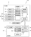
- FIG. 1 is a diagram showing a configuration of an operation teaching system according to the first embodiment of the present invention.
- the operation teaching system 1 in the first embodiment of the present invention teaches the operation to the work machine 2.
- the motion teaching system 1 includes a work machine 2 and a mobile terminal 3 capable of communicating with the work machine 2 via a network.
- the work machine 2 is a machine that performs work with the attachment 30, for example, a hydraulic excavator.
- the work machine 2 includes a lower traveling body 21, an upper swivel body 22, a swivel device 24, an attachment 30, and a cylinder 40.
- the lower traveling body 21 runs the work machine 2 and includes, for example, a crawler.
- the upper swivel body 22 is rotatably attached to the upper part of the lower traveling body 21.
- a cab (driver's cab) 23 is provided at the front portion of the upper swing body 22.
- the swivel device 24 swivels the upper swivel body 22.
- the attachment 30 is attached to the upper swing body 22 so as to be rotatable in the vertical direction.
- the attachment 30 includes a boom 31, an arm 32, and a bucket 33.
- the boom 31 is rotatably (undulating) attached to the upper swing body 22.
- the arm 32 is rotatably attached to the boom 31.
- the bucket 33 is rotatably attached to the arm 32.
- the bucket 33 excavates, smoothes, and scoops a work object such as earth and sand.
- the cylinder 40 rotates the attachment 30 by flood control.
- the cylinder 40 is a hydraulic telescopic cylinder.
- the cylinder 40 includes a boom cylinder 41, an arm cylinder 42, and a bucket cylinder 43.
- the boom cylinder 41 rotationally drives the boom 31 with respect to the upper swing body 22.
- the base end portion of the boom cylinder 41 is rotatably attached to the upper swing body 22.
- the tip of the boom cylinder 41 is rotatably attached to the boom 31.
- the arm cylinder 42 rotationally drives the arm 32 with respect to the boom 31.
- the base end portion of the arm cylinder 42 is rotatably attached to the boom 31.
- the tip of the arm cylinder 42 is rotatably attached to the arm 32.
- the bucket cylinder 43 rotates the bucket 33 with respect to the arm 32.
- the base end portion of the bucket cylinder 43 is rotatably attached to the arm 32.
- the tip of the bucket cylinder 43 is rotatably attached to the link member 34 rotatably attached to the bucket 33.
- the work machine 2 further includes an operation lever 51 (see FIG. 2), an angle sensor 52, and an inclination angle sensor 60.
- the operating lever 51 is operated by an operator to operate the swivel device 24 and the attachment 30.
- the operating lever 51 is provided in the cab 23.
- the angle sensor (turning angle detection device) 52 detects the turning angle of the upper turning body 22 with respect to the lower traveling body 21.
- the angle sensor 52 is, for example, an encoder, a resolver or a gyro sensor.
- the turning angle of the upper turning body 22 when the front of the upper turning body 22 coincides with the front of the lower traveling body 21 is set to 0 °.
- the tilt angle sensor (posture detection device) 60 detects the posture of the attachment 30.
- the tilt angle sensor 60 includes a boom tilt angle sensor 61, an arm tilt angle sensor 62, and a bucket tilt angle sensor 63.
- the boom tilt angle sensor 61 is attached to the boom 31 and detects the posture of the boom 31.
- the boom tilt angle sensor 61 is a sensor that acquires the tilt angle of the boom 31 with respect to the horizon, and is, for example, a tilt (acceleration) sensor or the like.
- the boom tilt angle sensor 61 may be a rotation angle sensor that detects the rotation angle of the boom foot pin (boom base end) or a stroke sensor that detects the stroke amount of the boom cylinder 41.
- the arm tilt angle sensor 62 is attached to the arm 32 and detects the posture of the arm 32.
- the arm tilt angle sensor 62 is a sensor that acquires the tilt angle of the arm 32 with respect to the horizon, and is, for example, a tilt (acceleration) sensor or the like.
- the arm tilt angle sensor 62 may be a rotation angle sensor that detects the rotation angle of the arm connecting pin (arm base end) or a stroke sensor that detects the stroke amount of the arm cylinder 42.
- the bucket tilt angle sensor 63 is attached to the link member 34 and detects the posture of the bucket 33.
- the bucket tilt angle sensor 63 is a sensor that acquires the tilt angle of the bucket 33 with respect to the horizon, and is, for example, a tilt (acceleration) sensor or the like.
- the bucket tilt angle sensor 63 may be a rotation angle sensor that detects the rotation angle of the bucket connecting pin (bucket base end) or a stroke sensor that detects the stroke amount of the bucket cylinder 43.
- FIG. 2 is a block diagram showing a configuration of an operation teaching system according to the first embodiment of the present invention.
- the work machine 2 includes a controller 11, a communication device 12, a storage device 13, a swivel device 24, an attachment 30, an operation lever 51, an angle sensor 52, and an inclination angle sensor 60. To be equipped.
- the communication device 12 communicates with the communication device 16 described later of the mobile terminal 3.
- the communication device 12 transmits various information to the mobile terminal 3 and receives various information from the mobile terminal 3.
- the controller 11 is, for example, a central processing unit (CPU), and executes various arithmetic processes based on the programs and data stored in the storage device 13.
- the controller 11 includes an information generation unit 111, a command generation unit 112, and an operation control unit 113.
- the storage device 13 is, for example, a flash memory or a magnetic disk device, which stores various programs and data and also functions as a work memory of the controller 11.
- the storage device 13 stores the posture information generated by the information generation unit 111 or the teaching point described later.
- the storage device 13 stores teaching point information in which the teaching position for teaching the position of the attachment 30 in a series of operations to be performed by the work machine 2 and the target posture information at the teaching position are associated with each other.
- the information generation unit 111 generates the posture information of the work machine 2. Specifically, the controller 11 generates posture information based on the turning angle of the upper turning body 22 detected by the angle sensor 52 and the posture of the attachment 30 detected by the tilt angle sensor 60.
- the communication device 12 receives a posture information request signal requesting posture information.
- the information generation unit 111 generates posture information when the posture information request signal is received by the communication device 12. At this time, the posture information is generated in a state where the tip of the bucket 33 is moved to a predetermined teaching position by the operator.
- the communication device 12 transmits the posture information generated by the information generation unit 111 to the mobile terminal 3.
- the communication device 12 receives the teaching point information transmitted by the mobile terminal 3.
- the command generation unit 112 generates a command for operating the work machine 2.
- the command generation unit 112 generates an automatic operation command for automatically operating the turning device 24 and the attachment 30 based on the teaching point information generated by the mobile terminal 3.
- the command generation unit 112 When the teaching point information is changed by the mobile terminal 3, the command generation unit 112 generates an automatic driving command based on the changed teaching point information.
- the operation control unit 113 operates the swivel device 24 and the attachment 30 based on the command generated by the command generation unit 112.
- the operation control unit 113 automatically operates the swivel device 24 and the attachment 30 based on the automatic operation command generated by the command generation unit 112.
- the work machine 2 will be automatically operated based on the automatic operation command.
- the mobile terminal 3 is operated by an operator at the work site, and is, for example, a tablet terminal.
- the mobile terminal 3 may be a smartphone or the like.
- the worker who operates the mobile terminal 3 and the operator who operates the work machine 2 may be the same person or different people.
- the mobile terminal 3 includes a controller 15, a communication device 16, a storage device 17, an input device 18, and a display 19.
- the communication device 16 communicates with the communication device 12 of the work machine 2.
- the communication device 16 transmits various information to the work machine 2 and receives various information from the work machine 2.
- the communication device 16 transmits a posture information request signal for requesting posture information to the work machine 2.
- the communication device 16 receives the posture information transmitted by the work machine 2.
- the controller 15 is, for example, a CPU, and executes various arithmetic processes based on the programs and data stored in the storage device 17.
- the controller 15 includes a point generation unit 151 and a point change unit 152.
- the point generation unit 151 sets a teaching position for teaching the position of the attachment 30 in a series of operations to be performed by the work machine 2 based on the posture information received from the work machine 2 by the communication device 16, and a target at the teaching position. Generate teaching point information associated with posture information. More specifically, the position of the attachment 30 is the position of the tip of the bucket 33.
- the point changing unit 152 changes the teaching point information generated by the point generating unit 151.
- the communication device 16 transmits the teaching point information generated by the point generation unit 151 to the work machine 2. Further, the communication device 16 transmits the teaching point information changed by the point changing unit 152 to the work machine 2.
- the storage device 17 is, for example, a flash memory or a magnetic disk device, which stores various programs and data and also functions as a work memory of the controller 15.
- the storage device 17 stores the posture information received from the work machine 2 or the teaching point information generated by the point generation unit 151.
- the input device 18 receives input from an operator and is, for example, a touch panel.
- the input device 18 may be a keyboard or the like.
- the input device 18 accepts a change by the operator of the teaching point information generated by the point generation unit 151.
- the input device 18 is an example of a change receiving unit.
- the point changing unit 152 changes the teaching point information based on the changed content received by the input device 18.
- the automatic operation command of the first embodiment causes the work machine 2 to perform a series of operations of excavating the ground with the bucket 33 and discharging the scooped earth and sand to the loading platform of the dump truck.
- the target of soil removal is not limited to dump trucks, but may be earth and sand pits or the like. The teaching point information required to generate the automatic operation command will be described below.
- FIG. 3 is a side view of the work site according to the first embodiment of the present invention as viewed from the side.
- the ground 70 to be excavated is located in front of the work machine 2 (on the left side of the paper), and the dump truck 80 is located behind the work machine 2 (on the right side of the paper).
- the X-axis is set in the horizontal direction (front-back direction of the work machine 2) with the boom foot pin 35 (see FIG. 1) having the base end portion of the boom 31 attached to the upper swing body 22 as the origin, and the vertical direction (work machine).
- the Z axis is set in the vertical direction of 2). In FIG. 3, only the bucket 33 of the attachments 30 is shown.
- the teaching point information required in the first embodiment is generated at seven teaching positions.
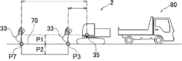
- the seven teaching positions include a reference position P1, a final excavation depth position P2, an excavation end position P3, a scooping position P4, a contact avoidance position P5, a soil discharge position P6, and an excavation start position P7.
- the operation of the work machine 2 in the first embodiment is an excavation operation in which the excavation target is excavated and the scooped soil is discharged to the dump truck 80.
- the operation of the work machine 2 is not limited to the excavation operation, and may be another operation.
- FIG. 4 is a side view for explaining a reference position, a final excavation depth position, an excavation start position, and an excavation end position in the first embodiment of the present invention.
- the reference position P1 is the height in the Z direction from the boom foot pin 35 to an arbitrarily set position.
- the reference position P1 indicates the height from the boom foot pin 35 to the upper part of the structure.
- the reference position P1 indicates the height from the boom foot pin 35 to the mark.
- the position of the reference position P1 in the X direction is arbitrary.
- the reference position P1 indicates the height from the boom foot pin 35 to a chopstick (not shown) installed on the ground 70 to be excavated.
- the final excavation depth position P2 is the depth at which the ground 70 to be excavated is finally excavated.
- the final excavation depth position P2 is set by numerical input as the depth with respect to the reference position P1.
- the excavation start position P7 is a position where excavation is started, and includes information on the x-coordinate of the tip of the bucket 33, the z-coordinate of the tip of the bucket 33, and the turning angle of the upper swivel body 22 with respect to the lower traveling body 21.
- the excavation end position P3 is a position at which excavation ends, and includes information on the x-coordinate of the tip of the bucket 33, the z-coordinate of the tip of the bucket 33, and the turning angle of the upper swivel body 22 with respect to the lower traveling body 21.
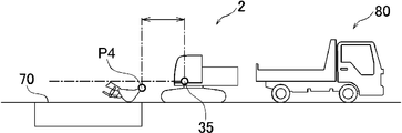
- FIG. 5 is a side view for explaining the scooping position in the first embodiment of the present invention.
- the scooping position P4 is a position where the bucket 33 scoops up earth and sand, and includes the x-coordinate of the tip of the bucket 33 and the z-coordinate of the tip of the bucket 33.
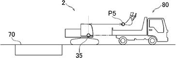
- FIG. 6 is a side view for explaining the contact avoidance position in the first embodiment of the present invention
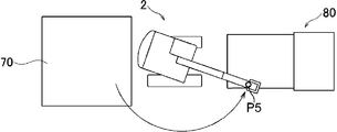
- FIG. 7 is a top view for explaining the contact avoidance position in the first embodiment of the present invention. is there.
- the contact avoidance position P5 is a position above the loading platform of the dump truck 80 to prevent the bucket 33 and the like from coming into contact with the dump truck 80.
- the contact avoidance position P5 includes information on the x-coordinate of the tip of the bucket 33, the z-coordinate of the tip of the bucket 33, and the turning angle of the upper swinging body 22 with respect to the lower traveling body 21.
- FIG. 8 is a side view for explaining the soil removal position in the first embodiment of the present invention
- FIG. 9 is a top view for explaining the soil removal position in the first embodiment of the present invention. is there.
- the soil discharge position P6 is a position for soil discharge to the loading platform of the dump truck 80, and is the x-coordinate of the tip of the bucket 33, the z-coordinate of the tip of the bucket 33, and the lower traveling body. Includes information on the turning angle of the upper swinging body 22 with respect to 21.
- an application for creating teaching point information is executed.
- the display 19 of the mobile terminal 3 displays a work action selection screen for accepting a selection by a worker of the work action for generating teaching point information from a plurality of types of work actions. ..
- the operator selects a work operation for generating teaching point information on the displayed work operation selection screen.
- the worker selects a work operation of excavating the ground with the bucket 33 and discharging the scooped earth and sand to the loading platform of the dump truck.
- the input device 18 of the mobile terminal 3 accepts the operator's selection of work operation. Then, the process of sequentially acquiring the posture information at the above seven teaching positions is executed.
- FIG. 10 is a diagram showing an example of a setting screen displayed on the display of the mobile terminal in the teaching point information generation process of the first embodiment of the present invention.
- the display 19 of the mobile terminal 3 displays the setting screen 90 as shown in FIG.
- the setting screen 90 presents a teaching operation to be performed by the operator of the work machine 2.
- an explanatory text 91 explaining the teaching operation performed by the operator of the work machine 2 a switch image 92, and an illustration image 93 showing a teaching position for acquiring posture information are displayed.
- FIG. 10 a setting screen 90 for acquiring posture information at the excavation end position P3 is shown.
- the operator of the work machine 2 moves the tip of the bucket 33 to the teaching position.
- the operation lever 51 of the work machine 2 accepts an operation by the operator.
- the operator of the work machine 2 operates the operation lever 51 so as to align the tip of the bucket 33 with the excavation end position P3.
- the communication device 16 of the mobile terminal 3 transmits a posture information request signal for requesting the posture information to the work machine 2.
- the communication device 12 of the work machine 2 receives the posture information request signal transmitted by the mobile terminal 3.
- the information generation unit 111 of the work machine 2 generates posture information at the timing when the posture information request signal is received.
- the posture information indicates the turning angle of the upper swinging body 22 and the posture of the attachment 30 at the excavation end position P3.
- the communication device 12 transmits the posture information generated by the information generation unit 111 to the mobile terminal 3.
- the communication device 16 of the mobile terminal 3 receives the posture information transmitted by the work machine 2.
- the point generation unit 151 teaches the position of the attachment 30 in a series of operations to be performed by the work machine 2 based on the posture information received by the communication device 16, and the target posture at the teaching position. Generate teaching point information associated with the information. For example, the point generation unit 151 generates teaching point information in which the excavation end position P3 presented on the setting screen 90 and the posture information at the excavation end position P3 received by the communication device 16 are associated with each other.
- the point generation unit 151 stores the generated teaching point information in the storage device 17.
- the point generation unit 151 of the mobile terminal 3 When such a teaching operation is performed for all the teaching positions, the point generation unit 151 of the mobile terminal 3 generates seven teaching point information based on the seven posture information. These teaching point information is shared with the work machine 2. That is, the communication device 16 of the mobile terminal 3 transmits the teaching point information generated by the point generation unit 151 to the work machine 2. The communication device 12 of the work machine 2 receives the teaching point information transmitted by the mobile terminal 3, and stores the received teaching point information in the storage device 13.
- the command generation unit 112 of the work machine 2 moves the tip of the bucket 33 from the excavation start position P7 to the excavation end position P3 in order to excavate the excavation target, and scoops up the tip of the bucket 33 in order to scoop up the earth and sand P4.
- An automatic operation command for causing the work machine 2 to perform a series of operations including an operation of discharging soil at the soil discharge position P6 and an operation of returning the tip of the bucket 33 to the excavation start position P7 is generated. Based on this automatic operation command, the work machine 2 will be automatically operated.
- the operation control unit 113 automatically operates the swivel device 24 and the attachment 30 based on the automatic operation command generated by the command generation unit 112.
- the work machine 2 is repeatedly and automatically operated for a plurality of work targets according to the generated teaching contents (for example, seven teaching point information). At this time, in a certain work target, the position or shape of the work target may differ from the generated teaching content. Therefore, the point changing unit 152 changes the teaching point information generated by the point generating unit 151.
- FIG. 11 is a side view for explaining the change of the excavation start position and the excavation end position in the first embodiment of the present invention.
- the excavation start position P7 at the work site is higher than the excavation start position P7 of the current teaching information
- the excavation end position P3 at the work site is lower than the excavation end position P3 of the current teaching information.
- the worker at the work site executes the application for changing the teaching point information on the mobile terminal 3.
- the teaching point information set earlier is called.
- the point changing unit 152 changes the z-coordinate of the excavation start position P7 and the z-coordinate of the excavation end position P3 in order.
- the display 19 of the mobile terminal 3 displays a change acceptance screen for accepting selection by the operator of the teaching position to be changed.
- the operator selects the teaching position to be changed on the displayed change acceptance screen.
- the input device 18 of the mobile terminal 3 accepts the change of the teaching position by the operator.
- the excavation start position P7 is changed, the operator moves the image showing the bucket 33 displayed on the change acceptance screen from the current excavation start position to the changed excavation start position.
- the point changing unit 152 changes the z-coordinate of the excavation start position P7 according to the position of the excavation start position P7 after the change received by the input device 18.
- the point changing unit 152 also changes the posture information according to the excavation start position P7 after the change.
- the input device 18 does not move the image showing the bucket 33 from the current excavation start position to the changed excavation start position, but is a value indicating how much the excavation start position is changed in the Z-axis direction. Input may be accepted.
- FIG. 12 is a top view for explaining changes in the contact avoidance position and the soil discharge position in the first embodiment of the present invention.
- the point changing unit 152 sequentially changes the turning angle of the upper turning body 22 with respect to the lower running body 21 at the contact avoidance position P5 and the turning angle of the upper turning body 22 with respect to the lower running body 21 at the soil discharge position P6.
- the point changing unit 152 changes the turning angle of the contact avoiding position P5 according to the changed position of the contact avoiding position P5 received by the input device 18.
- the point changing unit 152 also changes the posture information according to the contact avoidance position P5 after the change.
- the point changing unit 152 may change not only the turning angle but also the x-coordinate and the z-coordinate of the tip of the bucket 33.
- the input device 18 does not move the image showing the bucket 33 from the current contact avoidance position to the changed contact avoidance position, but accepts input of a value indicating how much the contact avoidance position is changed. May be good.
- the soil discharge position P6 is also changed in the same manner as the contact avoidance position P5.
- the point changing unit 152 stores the changed teaching point information in the storage device 17.
- the communication device 16 of the mobile terminal 3 transmits the teaching point information changed by the point changing unit 152 to the work machine 2.
- the communication device 12 of the work machine 2 receives the changed teaching point information, and stores the received changed teaching point information in the storage device 13.
- the command generation unit 112 generates an automatic operation command based on the changed teaching point information. As a result, the work machine 2 is automatically operated based on the changed automatic operation command.
- the turning device 24 and the attachment 30 of the work machine 2 are automatically operated based on the automatic operation command. Then, when the teaching point information is changed by the mobile terminal 3, an automatic operation command is generated based on the changed teaching point information, and the turning device 24 of the work machine 2 is generated based on the generated automatic operation command. And the attachment 30 is automatically operated. Since the teaching point information is changed by the mobile terminal 3, the operator does not have to operate the work machine 2 to regenerate the changed teaching point information. Then, the worker can change the teaching point information on the spot while checking the work target by bringing the mobile terminal 3 to the work site. Thereby, work efficiency can be improved.
- the motion teaching system further includes an ambient condition acquisition device that acquires the ambient condition of the work site.
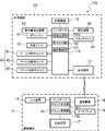
- FIG. 13 is a block diagram showing the configuration of the motion teaching system according to the second embodiment of the present invention
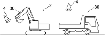
- FIG. 14 is a side view of the work site according to the second embodiment of the present invention.
- the motion teaching system 101 includes a work machine 2, a mobile terminal 3A, and an ambient situation acquisition device 4.
- the same components as those in the first embodiment are designated by the same reference numerals, and the description thereof will be omitted.
- the surrounding condition acquisition device 4 acquires the surrounding condition of the work site.
- the surrounding condition acquisition device 4 is, for example, a camera or a lidar (LIDAR: Light Detection And Ringing).
- the operation teaching system 101 may include one ambient situation acquisition device 4, or may include a plurality of ambient situation acquisition devices 4. As shown in FIG. 14, in the second embodiment, the motion teaching system 101 obtains the surrounding conditions of the surrounding condition acquisition device 4 arranged at the position of acquiring the surrounding condition of the attachment 30 and the stop position of the dump truck 80. It is provided with an ambient condition acquisition device 4 arranged at a position to acquire.
- the ambient condition acquisition device 4 transmits the acquired information indicating the ambient condition to the controller 11 of the work machine 2 via the communication device 12.
- the controller 11 transmits the received information indicating the surrounding condition to the mobile terminal 3A via the communication device 12.
- the surrounding situation acquisition device 4 may directly transmit the acquired information indicating the surrounding situation to the controller 15 via the communication device 16.
- the mobile terminal 3A includes a controller 15A, a communication device 16, a storage device 17, an input device 18, and a display 19.
- the controller 15A includes a point generation unit 151 and a point change unit 152A.
- the point changing unit 152A of the mobile terminal 3A automatically changes the teaching point information based on the surrounding conditions acquired by the surrounding condition acquisition device 4. For example, in FIG. 14, when there is an obstacle such as a stone in front of the attachment 30, the point changing portion 152A changes the excavation end position P3 or the scooping position P4 so that the attachment 30 does not interfere with the obstacle.
- the surrounding situation acquisition device 4 when the surrounding situation acquisition device 4 is a camera, the surrounding situation acquisition device 4 acquires an image obtained by photographing the surroundings of the attachment 30.
- the point changing unit 152A analyzes the image and detects the position and shape of an obstacle existing in front of the work machine 2.
- the point changing unit 152A detects an obstacle at the current excavation end position P3
- the point changing unit 152A changes the excavation end position P3 and the scooping position P4 to a position where no obstacle exists.
- the point changing unit 152A changes the contact avoidance position P5 or the soil discharge position P6.
- the ambient condition acquisition device 4 when the ambient condition acquisition device 4 is a camera, the ambient condition acquisition device 4 acquires an image obtained by photographing the dump truck 80 from above.
- the point changing unit 152A analyzes the image and determines whether or not the dump truck 80 is stopped at a predetermined reference stop position. Detects the position and shape of an obstacle existing in front of the work machine 2.
- the point changing unit 152A determines that the dump truck 80 is not stopped at the reference stop position, the point changing unit 152A changes the contact avoidance position P5 to a position where the dump truck 80 does not come into contact with the dump truck 80, and at the same time, above the loading platform of the dump truck 80.
- the soil discharge position P6 is changed.
- the movement of the automatic operation of the work machine 2 can be corrected according to the surrounding conditions acquired by the ambient condition acquisition device 4.
- the teaching point information is automatically changed based on the surrounding conditions of the work site.
- the operation of the automatic operation of the work machine 2 can be automatically corrected.
- work efficiency can be improved.
- the operation teaching system 1 of the first embodiment seven teaching point information is generated, and an automatic operation command is generated based on these.
- the operation between the adjacent teaching positions was determined by the controller 11 of the work machine 2.
- the operation control unit 113 of the controller 11 starts the work at the excavation start position P7.
- the operation between the excavation start position P7 and the excavation end position P3 is determined so that the work is completed at the excavation end position P3.
- the motion control unit 113 is operated so that the tip of the bucket 33 moves on a straight line connecting the excavation start position P7 and the excavation end position P3. Therefore, the generated automatic operation command lacked detail.
- FIG. 15 is a block diagram showing a configuration of an operation teaching system according to a third embodiment of the present invention.
- the motion teaching system 102 includes a work machine 2B and a mobile terminal 3.
- the work machine 2B includes a controller 11B, a communication device 12, a storage device 13, a swivel device 24, an attachment 30, an operation lever 51, an angle sensor 52, an operation amount detection device 53, and an inclination angle sensor 60. To be equipped.
- the work machine 2B further includes an operation amount detecting device 53.
- the operation amount detection device 53 continuously detects the type of operation and the operation amount of the operation lever 51.
- the types of operation of the operation lever 51 include raising the boom 31, lowering the boom 31, pushing the arm 32, pulling the arm 32, excavating the bucket 33, and removing soil from the bucket 33.
- the angle sensor 52 continuously detects the turning angle of the upper swinging body 22 that continuously changes by operating the operating lever 51.
- the tilt angle sensor 60 continuously detects the posture of the attachment 30 that continuously changes due to the operation of the operating lever 51.
- the controller 11B of the work machine 2B includes an information generation unit 111B, a command generation unit 112, and an operation control unit 113.
- the information generation unit 111B includes the type and amount of operation of the operation lever 51 continuously detected by the operation amount detection device 53, the turning angle of the upper swing body 22 continuously detected by the angle sensor 52, and the inclination.
- the posture information associated with the posture of the attachment 30 continuously detected by the angle sensor 60 is continuously generated. This posture information is generated when the operator operates the work machine 2B and the work machine 2B actually performs the same series of operations as the automatic operation.
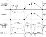
- FIG. 16 is a diagram showing an example of posture information generated in the third embodiment of the present invention.
- the posture information shown in FIG. 16 includes information 201 indicating the type of operation and continuous operation amount of the operation lever 51, information 202 indicating the continuous turning angle of the upper swing body 22, and continuous tip position of the bucket 33.
- Information 203 which indicates a specific movement, is shown.
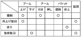
- FIG. 17 is a diagram showing an example of a correspondence relationship between the type of operation performed by the operation lever 51 and a specific operation pattern in the third embodiment of the present invention.
- the operation of the boom 31, the operation of the arm 32, the operation of the bucket 33, and the operation of turning are performed for each of the operation patterns of excavation, lifting turning, soil removal, and returning turning. Is shown.
- the circle indicates that the operation has been performed.
- the point generation unit 151 of the controller 15 of the mobile terminal 3 extracts the operation pattern of the operation lever 51 based on the posture information continuously generated by the information generation unit 111B of the work machine 2B. Specifically, the point generation unit 151 extracts the operation patterns of excavation, lifting turn, earth removal, and return turn based on the information 201 of the operation type and the operation amount of the operation lever 51 included in the attitude information. .. Then, the point generation unit 151 is the first teaching point information 211 which is the teaching point information when the operation pattern of the operation lever 51 is switched, and the teaching point information when the operation pattern of the operation lever 51 is continued. The second teaching point information 212 is generated.
- FIG. 16 a large black circle indicates the timing at which the first teaching point information 211 is generated.
- the five first teaching point information 211 shown in FIG. 16 includes five teaching point information (excavation end position P3, scooping position P4, contact avoidance position P5, soil discharge position P6, and the above seven teaching point information. It corresponds to the excavation start position P7).
- the excavation end position P3 and the scooping position P4 overlap.
- each of the first teaching point information 211 is generated when the operation pattern of the operation lever 51 is switched.
- the timing at which the operation of the operation lever 51 is started and the operation amount of the operation lever 51 increases from zero is included in the timing at which the operation pattern of the operation lever 51 is switched. Further, the timing at which all the operations of the operating lever 51 are completed and the operating amount of the operating lever 51 is reduced to zero is included in the timing at which the operating pattern of the operating lever 51 is switched.
- each of the plurality of second teaching point information 212 is generated between the two first teaching point information 211.
- each of the plurality of second teaching point information 212 is generated when the operation pattern of the operation lever 51 is continued. ing.
- the command generation unit 112 of the controller 11 of the work machine 2B generates an automatic operation command based on the first teaching point information 211 and the second teaching point information 212 generated by the point generation unit 151 of the mobile terminal 3.
- the command generation unit 112 can generate a more detailed automatic operation command. Therefore, it is possible to make the work machine 2 perform more complicated movements by automatic operation. Further, when the posture information is generated by the operation of the skilled operator, the movement of the skilled operator can be reproduced by automatic driving.
- the point generation unit 151 of the mobile terminal 3 classifies the posture information indicating a series of movements into a plurality of posture information based on the information of the operation type and the operation amount of the operation lever 51 included in the posture information.
- the timing at which the operation pattern is switched is different from the timing at which the operation of the operation lever 51 is started, that is, the timing at which the operation amount of the operation lever 51 increases from zero, and the timing after the operation amount of the operation lever 51 is reduced.
- the point generation unit 151 classifies the posture information indicating a series of operations into four posture information according to the operation patterns of excavation, lifting turn, soil removal, and return turn, based on the timing at which the operation pattern is switched and the type of operation.
- the timing when the operation for pulling the arm 32 is started (the timing when the operation amount of the operation for pulling the arm 32 increases from zero) and the turning of the upper swing body 22 are started. It is a period between the timing (the timing at which the operation amount of the operation of turning the upper swing body 22 increases from zero).
- the operation patterns corresponding to the lift turning include the timing when the turning of the upper turning body 22 is started (the timing when the operation amount of the operation for turning the upper turning body 22 increases from zero) and the earth removal of the bucket 33 start. It is a period between the timing (the timing when the operation amount of the operation of discharging the soil to the bucket 33 increases from zero).
- the operation patterns corresponding to the soil removal are the timing when the soil removal of the bucket 33 is started (the timing when the operation amount of the operation for discharging the soil to the bucket 33 increases from zero) and the rotation of the upper swivel body 22 It is a period between the timing (the timing when the operation amount of the operation of turning the upper swing body 22 increases from zero).
- the operation patterns corresponding to the return turning are the timing when the turning of the upper turning body 22 is started (the timing when the operation amount of the operation for turning the upper turning body 22 increases from zero) and the turning of the upper turning body 22. It is a period between the end timing (the timing when the operation amount of the operation of turning the upper swing body 22 is reduced to zero).
- the command generation unit 112 of the controller 11 of the work machine 2B generates an automatic operation command for each of a plurality of posture information classified by the point generation unit 151 of the mobile terminal 3.
- the posture information indicating a series of movements into a plurality of posture information
- the posture information classified into soil removal it can be seen that only the bucket 33 is rotated without rotating the upper swivel body 22.
- it becomes easy to generate an automatic driving command for each of the classified posture information so that the load required for generating the automatic driving command can be reduced.
- the posture information shown in FIG. 16 is an example.
- the boom 31 or arm 32 is operated in the soil removal classification.
- An automatic operation command will be generated to operate.
- the type and amount of operation of the continuously detected operating lever 51 and the continuously detected upper swing body 22 The posture information in which the turning angle of the above is associated with the continuously detected posture of the attachment 30 is continuously generated. Based on this posture information, the operation pattern of the operation lever 51 is extracted, and the first teaching point information 211 which is the teaching point information when the operation pattern is switched and the teaching point information when the operation pattern is continued are used. A certain second teaching point information 212 is generated. By generating the first teaching point information 211 and the second teaching point information 212, the command generation unit 112 can generate a more detailed automatic operation command. Therefore, in the automatic operation, the swivel device 24 and the attachment 30 of the work machine 2 can perform more complicated movements. Further, when the posture information is generated by the operation of the skilled operator, the movement of the skilled operator can be reproduced in the automatic driving.
- the posture information indicating a series of operations is divided into a plurality of posture information based on the information of the operation type and the operation amount of the operation lever 51. Then, an automatic driving command is generated for each of the classified posture information.
- the posture information indicating a series of movements is divided into a plurality of posture information based on the information of the operation type and the operation amount of the operation lever 51. Then, an automatic driving command is generated for each of the classified posture information.
- the motion teaching system 102 in the third embodiment may further include an ambient situation acquisition device 4 as in the motion teaching system 101 of the second embodiment.
- the present invention is not limited to the configuration in which the controller 11 of the work machine 2 generates the posture information, the controller 15 of the mobile terminal 3 may generate the posture information, and the work machine 2 and the mobile terminal 3 are Another device may generate the attitude information. Further, the present invention is not limited to the configuration in which the controller 11 of the work machine 2 generates an automatic operation command, and the controller 15 of the mobile terminal 3 may generate an automatic operation command, and the work machine 2 and the mobile terminal 3 may generate an automatic operation command. Another device may generate an automatic operation command.
- the motion teaching system is for operating the work machine, a portable terminal capable of communicating with the work machine, an information generation unit for generating posture information of the work machine, and the work machine.
- the work machine is provided with a command generation unit for generating the command of the above, and the work machine can rotate the lower traveling body, the upper rotating body rotatably attached to the upper part of the lower traveling body, and the upper rotating body.
- It has a detection device and an operation control unit that operates the swivel device and the attachment based on the command generated by the command generation unit, and the information generation unit is detected by the swivel angle detection device.
- the posture information is generated based on the turning angle of the upper swing body and the posture of the attachment detected by the posture detecting device, and the mobile terminal is based on the posture information generated by the information generation unit.
- a point generation unit that generates teaching point information in which the teaching position that teaches the position of the attachment in a series of operations to be performed by the work machine and the posture information that is the target at the teaching position are associated with each other, and the above-mentioned It has a point changing unit that changes the teaching point information generated by the point generating unit, and the command generating unit has the turning device and the swivel device based on the teaching point information generated by the point generating unit.
- An automatic operation command for automatically operating the attachment is generated, and the command generation unit automatically generates the teaching point information based on the changed teaching point information when the teaching point information is changed by the point changing unit.
- An operation command is generated, and the operation control unit automatically operates the turning device and the attachment based on the automatic operation command generated by the command generation unit.
- the swivel device and attachment of the work machine are automatically operated based on the automatic operation command. Then, when the teaching point information is changed by the mobile terminal, an automatic operation command is generated based on the changed teaching point information, and the turning device and the attachment of the work machine are generated based on the generated automatic operation command. It operates automatically. Since the teaching point information is changed by the mobile terminal, the operator does not have to operate the work machine to regenerate the changed teaching point information. Then, the worker can change the teaching point information on the spot while checking the work target by bringing the mobile terminal to the work site. Thereby, work efficiency can be improved.
- the work machine continuously detects an operation lever operated by an operator to operate the turning device and the attachment, and the type and amount of operation of the operation lever.
- the operation amount detecting device further comprises an operation amount detecting device, the turning angle detecting device continuously detects the turning angle of the upper swivel body which is continuously changed by the operation of the operating lever, and the posture detecting device is a posture detecting device.
- the posture of the attachment which is continuously changed by the operation of the operation lever, is continuously detected, and the information generation unit continuously detects the type and operation of the operation lever of the operation lever, which is continuously detected by the operation amount detection device.
- the attitude information in which the amount, the turning angle of the upper swing body continuously detected by the turning angle detecting device, and the posture of the attachment continuously detected by the posture detecting device are associated with each other.
- the point generation unit continuously generates the operation pattern of the operation lever based on the posture information continuously generated by the information generation unit, and the teaching when the operation pattern is switched.
- the first teaching point information which is the point information and the second teaching point information which is the teaching point information when the operation pattern is continued may be generated.
- the continuously detected operation type and operation amount of the operating lever are associated with the continuously detected turning angle of the upper swing body and the continuously detected posture of the attachment.
- Posture information is continuously generated.
- the operation pattern of the operation lever is extracted, and the first teaching point information 211 which is the teaching point information when the operation pattern is switched and the teaching point information when the operation pattern is continued.
- the second teaching point information 212 is generated.
- the command generation unit can generate a more detailed automatic operation command. Therefore, in automatic operation, more complicated movements can be made to the swivel device and attachment of the work machine. Further, when the posture information is generated by the operation of the skilled operator, the movement of the skilled operator can be reproduced in the automatic driving.
- the point generation unit obtains the posture information indicating the series of operations in a plurality of postures based on the information of the operation type and the operation amount of the operation lever included in the posture information.
- the command generation unit may generate the automatic operation command for each of the plurality of posture information classified by the point generation unit.
- the posture information indicating a series of operations is divided into a plurality of posture information based on the information of the operation type and the operation amount of the operation lever. Then, an automatic driving command is generated for each of the classified posture information.
- the posture information indicating a series of movements into a plurality of posture information, it is possible to clarify the moving portion of the attachment and the turning angle of the upper swing body for each of the divided posture information. As a result, it becomes easy to generate an automatic driving command for each of the classified posture information, so that the load required for generating the automatic driving command can be reduced.
- the mobile terminal further has a change receiving unit for receiving a change of the teaching point information generated by the point generating unit by an operator, and the point changing unit receives the change.
- the teaching point information may be changed based on the change contents received by the department.
- the worker changes the generated teaching point information by the mobile terminal, and the teaching point information is changed based on the received change contents. Therefore, the worker can easily change the teaching point information by using the mobile terminal. Therefore, the operator can save the trouble of operating the work machine in order to change the teaching point information.
- a surrounding condition acquisition device for acquiring the surrounding condition of the work site is further provided, and the point changing unit is the teaching point based on the surrounding condition acquired by the surrounding condition acquisition device. You may change the information.
- the teaching point information is automatically changed based on the surrounding conditions of the work site. Therefore, for example, when an obstacle that interferes with the attachment is detected, the operation of the automatic operation of the work machine can be automatically corrected. As a result, work efficiency can be improved.
Landscapes
- Engineering & Computer Science (AREA)
- Mining & Mineral Resources (AREA)
- Mechanical Engineering (AREA)
- Civil Engineering (AREA)
- General Engineering & Computer Science (AREA)
- Structural Engineering (AREA)
- Life Sciences & Earth Sciences (AREA)
- General Life Sciences & Earth Sciences (AREA)
- Paleontology (AREA)
- Operation Control Of Excavators (AREA)
- Component Parts Of Construction Machinery (AREA)
- Physics & Mathematics (AREA)
- Computing Systems (AREA)
- Mathematical Physics (AREA)
- Theoretical Computer Science (AREA)
- Aviation & Aerospace Engineering (AREA)
- Radar, Positioning & Navigation (AREA)
- Remote Sensing (AREA)
- General Physics & Mathematics (AREA)
- Automation & Control Theory (AREA)
Abstract
携帯端末3のポイント生成部(151)は、上部旋回体(22)の旋回角度及びアタッチメント(30)の姿勢情報に基づいて、作業機械(2)に行わせる一連の動作におけるアタッチメント(30)の位置を教示する教示位置と、教示位置において目標とする姿勢情報とを対応付けたティーチングポイント情報を生成し、ポイント変更部(152)は、生成されたティーチングポイント情報を変更し、作業機械2の指令生成部(112)は、ティーチングポイント情報が変更された場合に、変更されたティーチングポイント情報に基づいて、旋回装置24及びアタッチメント(30)を自動で動作させるための自動運転指令を生成し、作業機械2の動作制御部(113)は、自動運転指令に基づいて、旋回装置(24)及びアタッチメント(30)を自動で動作させる。
Description
本発明は、作業機械に動作を教示する技術に関する。
例えば、特許文献1には、予め教示した掘削位置と放土位置とに基づいて、ショベルに一連の繰り返し動作を自動で行わせる自動運転ショベルが開示されている。
また、例えば、特許文献2には、バケットの先端点を目的位置に動かした後、ダイレクト設定スイッチが押されると、フロント装置の動き得る領域を設定するダイレクトティーチが開示されている。そして、特許文献2には、ダイレクトティーチで設定された数値を基準として、数値入力スイッチでその数値を変更することが開示されている。
ところで、作業対象の位置又は形状が予め教示した内容と異なる場合がある。両者の異なる程度が大きい場合、教示し直す必要があり、教示し直すために作業機械を動作させるのは作業効率を低下させる。両者の異なる程度が小さい場合、特許文献2のように数値変更で対応することも可能であるが、作業機械を操作するオペレータが教示し直す度に入力するのは作業効率を低下させる。
本発明の目的は、作業効率を向上させることができる技術を提供することである。
本発明の一局面に係る動作教示システムは、作業機械と、前記作業機械と相互に通信可能な携帯端末と、前記作業機械の姿勢情報を生成する情報生成部と、前記作業機械を動作させるための指令を生成する指令生成部と、を備え、前記作業機械は、下部走行体と、前記下部走行体の上部に旋回可能に取り付けられた上部旋回体と、前記上部旋回体を旋回させることが可能な旋回装置と、前記上部旋回体に回動可能に取り付けられたアタッチメントと、前記下部走行体に対する前記上部旋回体の旋回角度を検出する旋回角度検出装置と、前記アタッチメントの姿勢を検出する姿勢検出装置と、前記指令生成部によって生成された前記指令に基づいて、前記旋回装置及び前記アタッチメントを動作させる動作制御部と、を有し、前記情報生成部は、前記旋回角度検出装置によって検出された前記上部旋回体の旋回角度及び前記姿勢検出装置によって検出された前記アタッチメントの姿勢に基づいて、前記姿勢情報を生成し、前記携帯端末は、前記情報生成部によって生成された前記姿勢情報に基づいて、前記作業機械に行わせる一連の動作における前記アタッチメントの位置を教示する教示位置と、前記教示位置において目標とする前記姿勢情報とを対応付けたティーチングポイント情報を生成するポイント生成部と、前記ポイント生成部によって生成された前記ティーチングポイント情報を変更するポイント変更部と、を有し、前記指令生成部は、前記ポイント生成部によって生成された前記ティーチングポイント情報に基づいて、前記旋回装置及び前記アタッチメントを自動で動作させるための自動運転指令を生成し、前記指令生成部は、前記ポイント変更部によって前記ティーチングポイント情報が変更された場合に、変更された前記ティーチングポイント情報に基づいて、前記自動運転指令を生成し、前記動作制御部は、前記指令生成部によって生成された前記自動運転指令に基づいて、前記旋回装置及び前記アタッチメントを自動で動作させる。
本発明によれば、作業効率を向上させることができる。
以下、本発明の好適な実施形態について、図面を参照しつつ説明する。なお、以下の実施形態は、本発明を具体化した一例であって、本発明の技術的範囲を限定するものではない。
(第1実施形態)
図1は、本発明の第1実施形態における動作教示システムの構成を示す図である。
図1は、本発明の第1実施形態における動作教示システムの構成を示す図である。
本発明の第1実施形態における動作教示システム1は、作業機械2に動作を教示する。図1に示すように、動作教示システム1は、作業機械2と、作業機械2とネットワークを介して相互に通信可能な携帯端末3とを備える。
図1に示すように、作業機械2は、アタッチメント30で作業を行う機械であり、例えば油圧ショベルである。作業機械2は、下部走行体21と、上部旋回体22と、旋回装置24と、アタッチメント30と、シリンダ40とを備える。
下部走行体21は、作業機械2を走行させ、例えばクローラを備える。上部旋回体22は、下部走行体21の上部に旋回可能に取り付けられる。上部旋回体22の前部には、キャブ(運転室)23が設けられている。旋回装置24は、上部旋回体22を旋回させる。
アタッチメント30は、上下方向に回動可能に上部旋回体22に取り付けられる。アタッチメント30は、ブーム31と、アーム32と、バケット33とを備える。ブーム31は、上部旋回体22に回動可能(起伏可能)に取り付けられる。アーム32は、ブーム31に回動可能に取り付けられる。バケット33は、アーム32に回動可能に取り付けられる。バケット33は、土砂などの作業対象に対し、掘削したり、ならしたり、すくったりする。
シリンダ40は、アタッチメント30を油圧によって回動させる。シリンダ40は、油圧式の伸縮シリンダである。シリンダ40は、ブームシリンダ41と、アームシリンダ42と、バケットシリンダ43とを備える。
ブームシリンダ41は、上部旋回体22に対してブーム31を回転駆動させる。ブームシリンダ41の基端部は、上部旋回体22に回動可能に取り付けられる。ブームシリンダ41の先端部は、ブーム31に回動可能に取り付けられる。
アームシリンダ42は、ブーム31に対してアーム32を回転駆動させる。アームシリンダ42の基端部は、ブーム31に回動可能に取り付けられる。アームシリンダ42の先端部は、アーム32に回動可能に取り付けられる。
バケットシリンダ43は、アーム32に対してバケット33を回転駆動させる。バケットシリンダ43の基端部は、アーム32に回動可能に取り付けられる。バケットシリンダ43の先端部は、バケット33に回動可能に取り付けられたリンク部材34に、回動可能に取り付けられる。
また、作業機械2は、操作レバー51(図2参照)と、角度センサ52と、傾斜角センサ60とをさらに備える。
操作レバー51は、旋回装置24及びアタッチメント30を動作させるためにオペレータにより操作される。操作レバー51は、キャブ23内に設けられている。
角度センサ(旋回角度検出装置)52は、下部走行体21に対する上部旋回体22の旋回角度を検出する。角度センサ52は、例えば、エンコーダ、レゾルバ又はジャイロセンサである。本第1実施形態では、上部旋回体22の前方が下部走行体21の前方と一致するときの上部旋回体22の旋回角度を0°としている。
傾斜角センサ(姿勢検出装置)60は、アタッチメント30の姿勢を検出する。傾斜角センサ60は、ブーム傾斜角センサ61と、アーム傾斜角センサ62と、バケット傾斜角センサ63とを備える。
ブーム傾斜角センサ61は、ブーム31に取り付けられ、ブーム31の姿勢を検出する。ブーム傾斜角センサ61は、水平線に対するブーム31の傾斜角度を取得するセンサであり、例えば傾斜(加速度)センサ等である。なお、ブーム傾斜角センサ61は、ブームフットピン(ブーム基端)の回転角度を検出する回転角度センサ、又はブームシリンダ41のストローク量を検出するストロークセンサであってもよい。
アーム傾斜角センサ62は、アーム32に取り付けられ、アーム32の姿勢を検出する。アーム傾斜角センサ62は、水平線に対するアーム32の傾斜角度を取得するセンサであり、例えば傾斜(加速度)センサ等である。なお、アーム傾斜角センサ62は、アーム連結ピン(アーム基端)の回転角度を検出する回転角度センサ、又はアームシリンダ42のストローク量を検出するストロークセンサであってもよい。
バケット傾斜角センサ63は、リンク部材34に取り付けられ、バケット33の姿勢を検出する。バケット傾斜角センサ63は、水平線に対するバケット33の傾斜角度を取得するセンサであり、例えば傾斜(加速度)センサ等である。なお、バケット傾斜角センサ63は、バケット連結ピン(バケット基端)の回転角度を検出する回転角度センサ、又はバケットシリンダ43のストローク量を検出するストロークセンサであってもよい。
図2は、本発明の第1実施形態における動作教示システムの構成を示すブロック図である。
図2に示すように、作業機械2は、コントローラ11と、通信装置12と、記憶装置13と、旋回装置24と、アタッチメント30と、操作レバー51と、角度センサ52と、傾斜角センサ60とを備える。
通信装置12は、携帯端末3の後述する通信装置16と通信する。通信装置12は、携帯端末3へ種々の情報を送信するとともに、携帯端末3から種々の情報を受信する。
コントローラ11は、例えば中央演算処理装置(CPU)であり、記憶装置13に記憶されるプログラム及びデータに基づいて各種の演算処理を実行する。コントローラ11は、情報生成部111と、指令生成部112と、動作制御部113とを備える。
記憶装置13は、例えば、フラッシュメモリ又は磁気ディスク装置であり、各種のプログラム及びデータを記憶すると共に、コントローラ11のワークメモリとしても機能する。
記憶装置13は、情報生成部111によって生成された姿勢情報、又は後述するティーチングポイントを記憶する。記憶装置13は、作業機械2に行わせる一連の動作におけるアタッチメント30の位置を教示する教示位置と、教示位置において目標とする姿勢情報とを対応付けたティーチングポイント情報を記憶する。
情報生成部111は、作業機械2の姿勢情報を生成する。具体的には、コントローラ11は、角度センサ52が検出した上部旋回体22の旋回角度及び傾斜角センサ60が検出したアタッチメント30の姿勢に基づいて、姿勢情報を生成する。
通信装置12は、姿勢情報を要求する姿勢情報要求信号を受信する。情報生成部111は、通信装置12によって姿勢情報要求信号が受信された場合、姿勢情報を生成する。このとき、姿勢情報は、オペレータにより所定の教示位置にバケット33の先端を移動させた状態で生成される。通信装置12は、情報生成部111によって生成された姿勢情報を携帯端末3へ送信する。
また、通信装置12は、携帯端末3によって送信されたティーチングポイント情報を受信する。
指令生成部112は、作業機械2を動作させるための指令を生成する。指令生成部112は、携帯端末3で生成されたティーチングポイント情報に基づいて、旋回装置24及びアタッチメント30を自動で動作させるための自動運転指令を生成する。
指令生成部112は、携帯端末3によってティーチングポイント情報が変更された場合に、変更されたティーチングポイント情報に基づいて、自動運転指令を生成する。
動作制御部113は、指令生成部112によって生成された指令に基づいて、旋回装置24及びアタッチメント30を動作させる。動作制御部113は、指令生成部112によって生成された自動運転指令に基づいて、旋回装置24及びアタッチメント30を自動で動作させる。作業機械2は、自動運転指令に基づいて自動運転されることになる。
続いて、携帯端末3の構成について説明する。
図1に示すように、携帯端末3は、作業現場にいる作業者により操作され、例えばタブレット端末である。なお、携帯端末3は、スマートフォン等であってもよい。なお、携帯端末3を操作する作業者と、作業機械2を操作するオペレータとは、同じ人物であってもよいし、異なる人物であってもよい。
図2に示すように、携帯端末3は、コントローラ15と、通信装置16と、記憶装置17と、入力装置18と、ディスプレイ19とを備える。
通信装置16は、作業機械2の通信装置12と通信する。通信装置16は、作業機械2へ種々の情報を送信するとともに、作業機械2から種々の情報を受信する。
通信装置16は、姿勢情報を作業機械2に要求する姿勢情報要求信号を作業機械2に送信する。通信装置16は、作業機械2によって送信された姿勢情報を受信する。
コントローラ15は、例えばCPUであり、記憶装置17に記憶されるプログラム及びデータに基づいて各種の演算処理を実行する。コントローラ15は、ポイント生成部151及びポイント変更部152を備える。
ポイント生成部151は、通信装置16によって作業機械2から受信された姿勢情報に基づいて、作業機械2に行わせる一連の動作におけるアタッチメント30の位置を教示する教示位置と、教示位置において目標とする姿勢情報とを対応付けたティーチングポイント情報を生成する。より具体的には、アタッチメント30の位置は、バケット33の先端の位置である。
ポイント変更部152は、ポイント生成部151によって生成されたティーチングポイント情報を変更する。
通信装置16は、ポイント生成部151によって生成されたティーチングポイント情報を作業機械2に送信する。また、通信装置16は、ポイント変更部152によって変更されたティーチングポイント情報を作業機械2に送信する。
記憶装置17は、例えば、フラッシュメモリ又は磁気ディスク装置であり、各種のプログラム及びデータを記憶すると共に、コントローラ15のワークメモリとしても機能する。
記憶装置17は、作業機械2から受信した姿勢情報、又はポイント生成部151によって生成されたティーチングポイント情報を記憶する。
入力装置18は、作業者からの入力を受け付け、例えばタッチパネルである。なお、入力装置18は、キーボード等であってもよい。入力装置18は、ポイント生成部151によって生成されたティーチングポイント情報の作業者による変更を受け付ける。入力装置18は、変更受付部の一例である。ポイント変更部152は、入力装置18によって受け付けた変更内容に基づいて、ティーチングポイント情報を変更する。
続いて、ティーチングポイント情報について説明する。
ここで、本第1実施形態の自動運転指令は、バケット33で地面を掘削し、すくった土砂をダンプトラックの荷台に排出する一連の動作を作業機械2に行わせる。なお、排土する対象はダンプトラックに限定されず、土砂ピット等であってもよい。以下、自動運転指令を生成するために必要なティーチングポイント情報について説明する。
図3は、本発明の第1実施形態における作業現場を側方から見た側面図である。
図3に示すように、作業機械2の前方(紙面の左方)には掘削対象の地面70があり、作業機械2の後方(紙面の右方)にはダンプトラック80が位置している。ブーム31の基端部を上部旋回体22に取り付けているブームフットピン35(図1参照)を原点として、水平方向(作業機械2の前後方向)にX軸が設定され、垂直方向(作業機械2の上下方向)にZ軸が設定される。なお、図3においては、アタッチメント30のうち、バケット33のみが図示されている。
本第1実施形態において必要なティーチングポイント情報は、7つの教示位置において生成される。7つの教示位置は、基準位置P1、最終掘削深さ位置P2、掘削終了位置P3、すくい上げ位置P4、接触回避位置P5、排土位置P6及び掘削開始位置P7を含む。なお、本第1実施形態における作業機械2の動作は、掘削対象を掘削し、すくい上げた土をダンプトラック80に排出する掘削動作である。作業機械2の動作は、掘削動作に限定されず、他の動作であってもよい。
図4は、本発明の第1実施形態において、基準位置、最終掘削深さ位置、掘削開始位置及び掘削終了位置を説明するための側面図である。
図4に示すように、基準位置P1は、ブームフットピン35から任意に設定された位置までのZ方向の高さである。例えば、土砂ピット等の構造物の高さが明確である場合、基準位置P1は、ブームフットピン35から構造物の上部までの高さを示す。また、丁張り等の現場測量を反映した目印が存在する場合、基準位置P1は、ブームフットピン35から目印までの高さを示す。X方向における基準位置P1の位置は任意である。図4では、基準位置P1は、ブームフットピン35から、掘削対象の地面70に設置した図示しない丁張りまでの高さを示す。
最終掘削深さ位置P2は、掘削対象の地面70を最終的に掘削する深さである。最終掘削深さ位置P2は、基準位置P1に対する深さとして数値入力により設定される。
掘削開始位置P7は、掘削を開始する位置であり、バケット33の先端のx座標、バケット33の先端のz座標、及び、下部走行体21に対する上部旋回体22の旋回角度の情報を含む。
掘削終了位置P3は、掘削を終了する位置であり、バケット33の先端のx座標、バケット33の先端のz座標、及び、下部走行体21に対する上部旋回体22の旋回角度の情報を含む。
図5は、本発明の第1実施形態において、すくい上げ位置を説明するための側面図である。
図5に示すように、すくい上げ位置P4は、バケット33で土砂をすくい上げる位置であり、バケット33の先端のx座標及びバケット33の先端のz座標を含む。
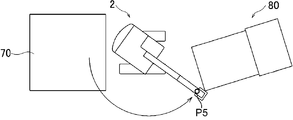
図6は、本発明の第1実施形態において、接触回避位置を説明するための側面図であり、図7は、本発明の第1実施形態において、接触回避位置を説明するための上面図である。
図6及び図7に示すように、接触回避位置P5は、ダンプトラック80の荷台の上方において、バケット33等がダンプトラック80に接触するのを回避する位置である。接触回避位置P5は、バケット33の先端のx座標、バケット33の先端のz座標、及び、下部走行体21に対する上部旋回体22の旋回角度の情報を含む。
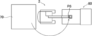
図8は、本発明の第1実施形態において、排土位置を説明するための側面図であり、図9は、本発明の第1実施形態において、排土位置を説明するための上面図である。
図8及び図9に示すように、排土位置P6は、ダンプトラック80の荷台に排土する位置であり、バケット33の先端のx座標、バケット33の先端のz座標、及び、下部走行体21に対する上部旋回体22の旋回角度の情報を含む。
次に、ティーチングポイント情報を生成する手順について説明する。まず、携帯端末3において、ティーチングポイント情報を作成するためのアプリケーションが実行される。アプリケーションが実行されると、例えば、携帯端末3のディスプレイ19は、複数種類の作業動作の中から、ティーチングポイント情報を生成する作業動作の作業者による選択を受け付けるための作業動作選択画面を表示する。作業者は、表示された作業動作選択画面において、ティーチングポイント情報を生成する作業動作を選択する。例えば、作業者は、バケット33で地面を掘削し、すくった土砂をダンプトラックの荷台に排出する作業動作を選択する。携帯端末3の入力装置18は、作業者による作業動作の選択を受け付ける。そして、上記の7つの教示位置における姿勢情報を順番に取得する処理が実行される。
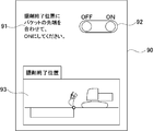
図10は、本発明の第1実施形態のティーチングポイント情報生成処理において、携帯端末のディスプレイに表示される設定画面の一例を示す図である。
ティーチングポイント情報生成処理において、携帯端末3のディスプレイ19は、図10に示すような設定画面90を表示する。設定画面90は、作業機械2のオペレータに行わせる教示動作を提示する。設定画面90には、作業機械2のオペレータが行う教示動作を説明する説明文91と、スイッチ画像92と、姿勢情報を取得する教示位置を示すイラスト画像93とが表示される。図10では、掘削終了位置P3における姿勢情報を取得する場合の設定画面90が図示されている。
作業機械2のオペレータは、教示位置にバケット33の先端を移動させる。作業機械2の操作レバー51は、オペレータによる操作を受け付ける。掘削終了位置P3における姿勢情報が取得される場合、作業機械2のオペレータは、掘削終了位置P3にバケット33の先端を合わせるように操作レバー51を操作する。
次に、携帯端末3を所持する作業者は、バケット33の先端が教示位置(掘削終了位置P3)に移動されたタイミングで、スイッチ画像92を「OFF」から「ON」に切り替える。
スイッチ画像92が「ON」に切り替えられると、携帯端末3の通信装置16は、姿勢情報を作業機械2に要求する姿勢情報要求信号を作業機械2に送信する。
次に、作業機械2の通信装置12は、携帯端末3によって送信された姿勢情報要求信号を受信する。
次に、作業機械2の情報生成部111は、姿勢情報要求信号が受信されたタイミングで姿勢情報を生成する。姿勢情報は、掘削終了位置P3における上部旋回体22の旋回角度及びアタッチメント30の姿勢を示す。
次に、通信装置12は、情報生成部111によって生成された姿勢情報を携帯端末3に送信する。
次に、携帯端末3の通信装置16は、作業機械2によって送信された姿勢情報を受信する。
次に、ポイント生成部151は、通信装置16によって受信された姿勢情報に基づいて、作業機械2に行わせる一連の動作におけるアタッチメント30の位置を教示する教示位置と、教示位置において目標とする姿勢情報とを対応付けたティーチングポイント情報を生成する。例えば、ポイント生成部151は、設定画面90に提示した掘削終了位置P3と、通信装置16によって受信された掘削終了位置P3における姿勢情報とを対応付けたティーチングポイント情報を生成する。
次に、ポイント生成部151は、生成したティーチングポイント情報を記憶装置17に記憶する。
このような教示動作がすべての教示位置に対して行われると、携帯端末3のポイント生成部151は、7つの姿勢情報に基づいて、7つのティーチングポイント情報を生成する。これらのティーチングポイント情報は、作業機械2と共有される。すなわち、携帯端末3の通信装置16は、ポイント生成部151によって生成されたティーチングポイント情報を作業機械2へ送信する。作業機械2の通信装置12は、携帯端末3によって送信されたティーチングポイント情報を受信し、受信したティーチングポイント情報を記憶装置13に記憶する。
作業機械2の指令生成部112は、掘削対象を掘削するためにバケット33の先端を掘削開始位置P7から掘削終了位置P3まで移動させる動作と、土砂をすくうためにバケット33の先端をすくい上げ位置P4まで移動させる動作と、上部旋回体22をダンプトラック80の方に旋回させながら、バケット33の先端を接触回避位置P5に移動させる動作と、排土するために排土位置P6に移動させる動作と、排土位置P6で排土させる動作と、バケット33の先端を掘削開始位置P7に戻す動作とを含む一連の動作を作業機械2に行わせる自動運転指令を生成する。この自動運転指令に基づいて、作業機械2が自動運転されることになる。
動作制御部113は、指令生成部112によって生成された自動運転指令に基づいて、旋回装置24及びアタッチメント30を自動的に動作させる。
続いて、ティーチングポイント情報の変更について説明する。
生成したティーチング内容(例えば、7つのティーチングポイント情報)に従って、複数の作業対象に対して、作業機械2が繰り返し自動運転される。このとき、ある作業対象では、作業対象の位置又は形状が、生成したティーチング内容と異なる場合がある。そこで、ポイント変更部152は、ポイント生成部151によって生成されたティーチングポイント情報を変更する。
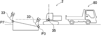
図11は、本発明の第1実施形態において、掘削開始位置及び掘削終了位置の変更について説明するための側面図である。
例えば、図11に示すように、作業現場の掘削開始位置P7が現在のティーチング情報の掘削開始位置P7よりも高く、作業現場の掘削終了位置P3が現在のティーチング情報の掘削終了位置P3よりも低い場合を考える。この場合、作業現場にいる作業者は、携帯端末3において、ティーチングポイント情報を変更するアプリケーションを実行させる。このアプリケーションにおいて、先に設定したティーチングポイント情報が呼び出される。そして、ポイント変更部152は、掘削開始位置P7のz座標、及び、掘削終了位置P3のz座標を順番に変更する。
例えば、携帯端末3のディスプレイ19は、変更させる教示位置の作業者による選択を受け付けるための変更受付画面を表示する。作業者は、表示された変更受付画面において、変更させる教示位置を選択する。そして、携帯端末3の入力装置18は、作業者による教示位置の変更を受け付ける。掘削開始位置P7が変更される場合、作業者は、変更受付画面に表示されたバケット33を示す画像を、現在の掘削開始位置から変更後の掘削開始位置に移動させる。ポイント変更部152は、入力装置18によって受け付けた変更後の掘削開始位置P7の位置に応じて、掘削開始位置P7のz座標を変更する。また、ポイント変更部152は、変更後の掘削開始位置P7に応じて姿勢情報も変更する。
なお、入力装置18は、バケット33を示す画像を、現在の掘削開始位置から変更後の掘削開始位置に移動させるのではなく、掘削開始位置をZ軸方向にどの程度変更するかを示す値の入力を受け付けてもよい。
図12は、本発明の第1実施形態において、接触回避位置及び排土位置の変更について説明するための上面図である。
また、図12に示すように、作業現場のダンプトラック80の停車位置が基準となる停車位置に対して傾いている場合を考える。この場合、作業現場にいる作業者は、携帯端末3において、ティーチングポイント情報を変更するアプリケーションを実行させる。ポイント変更部152は、接触回避位置P5の下部走行体21に対する上部旋回体22の旋回角度と、排土位置P6の下部走行体21に対する上部旋回体22の旋回角度とを順番に変更する。
例えば、接触回避位置P5が変更される場合、作業者は、変更受付画面に表示されたバケット33を示す画像を、現在の接触回避位置から変更後の接触回避位置に移動させる。ポイント変更部152は、入力装置18によって受け付けた変更後の接触回避位置P5の位置に応じて、接触回避位置P5の旋回角度を変更する。また、ポイント変更部152は、変更後の接触回避位置P5に応じて姿勢情報も変更する。なお、ポイント変更部152は、接触回避位置を変更する際に、旋回角度だけでなく、バケット33の先端のx座標及びz座標も変更してもよい。
また、入力装置18は、バケット33を示す画像を、現在の接触回避位置から変更後の接触回避位置に移動させるのではなく、接触回避位置をどの程度変更するかを示す値の入力を受け付けてもよい。なお、排土位置P6についても、接触回避位置P5と同様に変更される。
ポイント変更部152は、変更したティーチングポイント情報を記憶装置17に記憶する。
携帯端末3の通信装置16は、ポイント変更部152によって変更されたティーチングポイント情報を作業機械2に送信する。作業機械2の通信装置12は、変更されたティーチングポイント情報を受信し、受信した変更されたティーチングポイント情報を記憶装置13に記憶する。指令生成部112は、変更後のティーチングポイント情報に基づいて、自動運転指令を生成する。これにより、作業機械2は、変更後の自動運転指令に基づいて、自動運転されることになる。
以上に述べたように、本第1実施形態に係る動作教示システム1によれば、自動運転指令に基づいて、作業機械2の旋回装置24及びアタッチメント30が自動で動作される。そして、携帯端末3によってティーチングポイント情報が変更された場合には、変更されたティーチングポイント情報に基づいて自動運転指令が生成され、生成された自動運転指令に基づいて、作業機械2の旋回装置24及びアタッチメント30が自動で動作される。携帯端末3によってティーチングポイント情報が変更されるので、作業者は、変更されたティーチングポイント情報を生成し直すために作業機械2を動作させなくてもよい。そして、作業者は、携帯端末3を作業現場に持ち込むことで、作業対象を確認しながら、その場でティーチングポイント情報を変更することができる。これにより、作業効率を向上させることができる。
(第2実施形態)
第2実施形態では、動作教示システムが、作業現場の周囲状況を取得する周囲状況取得装置をさらに備える。
第2実施形態では、動作教示システムが、作業現場の周囲状況を取得する周囲状況取得装置をさらに備える。
図13は、本発明の第2実施形態における動作教示システムの構成を示すブロック図であり、図14は、本発明の第2実施形態における作業現場を側方から見た図である。
図13に示すように、動作教示システム101は、作業機械2と、携帯端末3Aと、周囲状況取得装置4とを備える。なお、第2実施形態において、第1実施形態と同じ構成については同じ符号を付し、説明を省略する。
周囲状況取得装置4は、作業現場の周囲状況を取得する。周囲状況取得装置4は、例えば、カメラ又はライダ(LIDAR:Light Detection And Ranging)である。動作教示システム101は、1つの周囲状況取得装置4を備えてもよいし、複数の周囲状況取得装置4を備えてもよい。図14に示すように、本第2実施形態において、動作教示システム101は、アタッチメント30の周囲状況を取得する位置に配置された周囲状況取得装置4と、ダンプトラック80の停車位置の周囲状況を取得する位置に配置された周囲状況取得装置4とを備える。
図13に示すように、周囲状況取得装置4は、取得した周囲状況を示す情報を、通信装置12を介して作業機械2のコントローラ11に送信する。コントローラ11は、受信した周囲状況を示す情報を、通信装置12を介して携帯端末3Aに送信する。なお、周囲状況取得装置4は、取得した周囲状況を示す情報を、通信装置16を介してコントローラ15に直接送信してもよい。
携帯端末3Aは、コントローラ15Aと、通信装置16と、記憶装置17と、入力装置18と、ディスプレイ19とを備える。コントローラ15Aは、ポイント生成部151及びポイント変更部152Aを備える。
携帯端末3Aのポイント変更部152Aは、周囲状況取得装置4によって取得された周囲状況に基づいて、ティーチングポイント情報を自動で変更する。例えば、図14において、アタッチメント30の前方に石等の障害物がある場合、ポイント変更部152Aは、アタッチメント30が障害物に干渉しないように、掘削終了位置P3又はすくい上げ位置P4を変更する。
例えば、周囲状況取得装置4がカメラである場合、周囲状況取得装置4は、アタッチメント30の周囲を撮影することによって得られた画像を取得する。ポイント変更部152Aは、画像を解析し、作業機械2の前方に存在する障害物の位置及び形状を検知する。ポイント変更部152Aは、現在の掘削終了位置P3に障害物を検知した場合、障害物が存在しない位置に掘削終了位置P3及びすくい上げ位置P4を変更する。
また、ダンプトラック80が基準となる停車位置に対して作業機械2に近すぎたり、傾いていたりしている場合、ポイント変更部152Aは、接触回避位置P5又は排土位置P6を変更する。
例えば、周囲状況取得装置4がカメラである場合、周囲状況取得装置4は、ダンプトラック80を上方から撮影することによって得られた画像を取得する。ポイント変更部152Aは、画像を解析し、予め決められている基準となる停車位置にダンプトラック80が停車しているか否かを判断する。作業機械2の前方に存在する障害物の位置及び形状を検知する。ポイント変更部152Aは、基準となる停車位置にダンプトラック80が停車していないと判断した場合、ダンプトラック80に接触しない位置に接触回避位置P5を変更するとともに、ダンプトラック80の荷台の上方に排土位置P6を変更する。
これにより、周囲状況取得装置4によって取得された周囲状況に応じて作業機械2の自動運転の動きを修正することができる。
以上に述べたように、本第2実施形態に係る動作教示システム101によれば、作業現場の周囲状況に基づいて、ティーチングポイント情報が自動で変更される。これにより、例えば、アタッチメント30に干渉する障害物が検出されたり、排土対象のダンプトラック80が移動したりした場合に、作業機械2の自動運転の動作を自動的に修正することができる。その結果、作業効率を向上させることができる。
(第3実施形態)
次に、第3実施形態の動作教示システムについて、図面を参照しつつ説明する。なお、第1実施形態と共通する構成及びそれにより奏される効果については説明を省略し、主に、第1実施形態と異なる点について説明する。なお、第1実施形態と同じ構成については、第1実施形態と同じ符号を付している。
次に、第3実施形態の動作教示システムについて、図面を参照しつつ説明する。なお、第1実施形態と共通する構成及びそれにより奏される効果については説明を省略し、主に、第1実施形態と異なる点について説明する。なお、第1実施形態と同じ構成については、第1実施形態と同じ符号を付している。
まず、ティーチングポイント情報を生成する手順について説明する。
第1実施形態の動作教示システム1では、7つのティーチングポイント情報が生成され、これらに基づいて自動運転指令が生成される。この場合、隣り合う教示位置間の動作は、作業機械2のコントローラ11が決定していた。具体的には、図4に示すように、掘削開始位置P7及び掘削終了位置P3のティーチングポイント情報が生成されると、コントローラ11の動作制御部113は、掘削開始位置P7で作業が開始され、掘削終了位置P3で作業が終了するように、掘削開始位置P7と掘削終了位置P3との間の動作を決定する。例えば、動作制御部113は、掘削開始位置P7と掘削終了位置P3とを結ぶ直線上をバケット33の先端が移動するように動作させる。そのため、生成される自動運転指令は詳細さに欠けていた。
図15は、本発明の第3実施形態における動作教示システムの構成を示すブロック図である。
動作教示システム102は、作業機械2Bと、携帯端末3とを備える。作業機械2Bは、コントローラ11Bと、通信装置12と、記憶装置13と、旋回装置24と、アタッチメント30と、操作レバー51と、角度センサ52と、操作量検出装置53と、傾斜角センサ60とを備える。
図15に示すように、作業機械2Bは、操作量検出装置53をさらに備える。操作量検出装置53は、操作レバー51の操作の種類及び操作量を連続的に検出する。ここで、操作レバー51の操作の種類とは、ブーム31の上げ、ブーム31の下げ、アーム32の押し、アーム32の引き、バケット33の掘削、及びバケット33の排土などである。
また、角度センサ52は、操作レバー51の操作により連続的に変化する上部旋回体22の旋回角度を連続的に検出する。同様に、傾斜角センサ60は、操作レバー51の操作により連続的に変化するアタッチメント30の姿勢を連続的に検出する。
作業機械2Bのコントローラ11Bは、情報生成部111Bと、指令生成部112と、動作制御部113とを備える。
情報生成部111Bは、操作量検出装置53によって連続的に検出された操作レバー51の操作の種類及び操作量と、角度センサ52によって連続的に検出された上部旋回体22の旋回角度と、傾斜角センサ60によって連続的に検出されたアタッチメント30の姿勢とを対応付けた姿勢情報を連続的に生成する。この姿勢情報は、オペレータが作業機械2Bを操作して、作業機械2Bが自動運転と同じ一連の動作を実際に行うことで生成される。
図16は、本発明の第3実施形態において生成される姿勢情報の一例を示す図である。図16に示す姿勢情報は、操作レバー51の操作の種類及び連続的な操作量を示す情報201と、上部旋回体22の連続的な旋回角度を示す情報202と、バケット33の先端位置の連続的な動きを示す情報203とを示している。
図17は、本発明の第3実施形態において操作レバー51により行われる操作の種類と、具体的な操作パターンとの対応関係の一例を示す図である。図17では、掘削、持上げ旋回、排土及び復帰旋回のそれぞれの操作パターンに対して、ブーム31の操作、アーム32の操作、バケット33の操作、及び、旋回の操作がそれぞれ行われたか否かを示している。図17において、操作が行われたことが丸印で示されている。
携帯端末3のコントローラ15のポイント生成部151は、作業機械2Bの情報生成部111Bによって連続的に生成された姿勢情報に基づいて、操作レバー51の操作パターンを抽出する。具体的には、ポイント生成部151は、姿勢情報に含まれる操作レバー51の操作の種類及び操作量の情報201に基づいて、掘削、持上げ旋回、排土及び復帰旋回の操作パターンをそれぞれ抽出する。そして、ポイント生成部151は、操作レバー51の操作パターンが切り替わったときのティーチングポイント情報である第1ティーチングポイント情報211と、操作レバー51の操作パターンが継続されているときのティーチングポイント情報である第2ティーチングポイント情報212とを生成する。
図16において、大きな黒丸は、第1ティーチングポイント情報211が生成されるタイミングを示している。図16に示される5つの第1ティーチングポイント情報211は、上記の7つのティーチングポイント情報のうちの5つのティーチングポイント情報(掘削終了位置P3、すくい上げ位置P4、接触回避位置P5、排土位置P6及び掘削開始位置P7)にそれぞれ相当している。なお、図16では、掘削終了位置P3とすくい上げ位置P4とが重なっている。操作レバー51の操作量と、図17に示す操作パターンとを照らし合わせることからわかるように、第1ティーチングポイント情報211の各々は、操作レバー51の操作パターンが切り替わったときに生成されている。なお、操作レバー51の操作が開始されて、操作レバー51の操作量がゼロから増加するタイミングは、操作レバー51の操作パターンが切り替わったタイミングに含まれる。また、操作レバー51の操作が全て終了されて、操作レバー51の操作量がゼロまで低減するタイミングは、操作レバー51の操作パターンが切り替わったタイミングに含まれる。
図16において、小さな黒丸は、第2ティーチングポイント情報212が生成されるタイミングを示している。複数の第2ティーチングポイント情報212の各々は、2つの第1ティーチングポイント情報211の間に生成されている。操作レバー51の操作量と図17に示す操作パターンとを照らし合わせることからわかるように、複数の第2ティーチングポイント情報212の各々は、操作レバー51の操作パターンが継続されているときに生成されている。
作業機械2Bのコントローラ11の指令生成部112は、携帯端末3のポイント生成部151によって生成された第1ティーチングポイント情報211及び第2ティーチングポイント情報212に基づいて、自動運転指令を生成する。第1ティーチングポイント情報211と第2ティーチングポイント情報212とが生成されることで、指令生成部112は、より詳細な自動運転指令を生成することができる。したがって、自動運転でより複雑な動きを作業機械2に行わせることができる。また、熟練オペレータの操作により姿勢情報が生成された場合には、熟練オペレータの動きを自動運転で再現させることができる。
また、携帯端末3のポイント生成部151は、姿勢情報に含まれる操作レバー51の操作の種類及び操作量の情報に基づいて、一連の動作を示す姿勢情報を複数の姿勢情報に区分する。図16では、操作パターンが切り替わるタイミングには、操作レバー51の操作が開始されるタイミング、すなわち、操作レバー51の操作量がゼロから増加するタイミング、及び操作レバー51の操作量が低減した後に別の種類の操作が行われるタイミングがある。ポイント生成部151は、操作パターンが切り替わるタイミング及び操作の種類から、一連の動作を示す姿勢情報を、掘削、持上げ旋回、排土及び復帰旋回の操作パターンに応じた4つの姿勢情報に区分する。
例えば、掘削に対応する操作パターンは、アーム32を引くための操作が開始されたタイミング(アーム32を引く操作の操作量がゼロから増加したタイミング)と、上部旋回体22の旋回が開始されたタイミング(上部旋回体22を旋回させる操作の操作量がゼロから増加したタイミング)との間の期間である。
また、持上げ旋回に対応する操作パターンは、上部旋回体22の旋回が開始されたタイミング(上部旋回体22を旋回させる操作の操作量がゼロから増加したタイミング)と、バケット33の排土が開始されたタイミング(バケット33に排土させる操作の操作量がゼロから増加したタイミング)との間の期間である。
また、排土に対応する操作パターンは、バケット33の排土が開始されたタイミング(バケット33に排土させる操作の操作量がゼロから増加したタイミング)と、上部旋回体22の旋回が開始されたタイミング(上部旋回体22を旋回させる操作の操作量がゼロから増加したタイミング)との間の期間である。
また、復帰旋回に対応する操作パターンは、上部旋回体22の旋回が開始されたタイミング(上部旋回体22を旋回させる操作の操作量がゼロから増加したタイミング)と、上部旋回体22の旋回が終了されたタイミング(上部旋回体22を旋回させる操作の操作量が低減してゼロになったタイミング)との間の期間である。
作業機械2Bのコントローラ11の指令生成部112は、携帯端末3のポイント生成部151によって区分された複数の姿勢情報毎に、自動運転指令を生成する。一連の動作を示す姿勢情報を複数の姿勢情報に区分することで、区分された姿勢情報毎に、アタッチメント30の動かす部分、及び上部旋回体22の旋回角度を明確にすることができる。例えば、排土に区分された姿勢情報からは、上部旋回体22を旋回させずに、バケット33だけを回動させることがわかる。これにより、区分した姿勢情報毎に自動運転指令を生成しやすくなるので、自動運転指令の生成に要する負荷を低減することができる。
なお、図16に示す姿勢情報は一例であり、例えば、排土の区分においてオペレータによりブーム31又はアーム32も動作させる操作が行われた場合には、排土の区分では、ブーム31又はアーム32も動作させる自動運転指令が生成されることになる。
以上に述べたように、本第3実施形態に係る動作教示システム102によれば、連続的に検出された操作レバー51の操作の種類及び操作量と、連続的に検出された上部旋回体22の旋回角度と、連続的に検出されたアタッチメント30の姿勢とを対応付けた姿勢情報が連続的に生成される。この姿勢情報に基づいて、操作レバー51の操作パターンが抽出され、操作パターンが切り替わったときのティーチングポイント情報である第1ティーチングポイント情報211と、操作パターンが継続されているときのティーチングポイント情報である第2ティーチングポイント情報212とが生成される。第1ティーチングポイント情報211と第2ティーチングポイント情報212とが生成されることで、指令生成部112は、より詳細な自動運転指令を生成することができる。したがって、自動運転において、より複雑な動きを作業機械2の旋回装置24及びアタッチメント30に行わせることができる。また、熟練オペレータの操作により姿勢情報が生成された場合には、熟練オペレータの動きを自動運転において再現させることができる。
また、操作レバー51の操作の種類及び操作量の情報に基づいて、一連の動作を示す姿勢情報が複数の姿勢情報に区分される。そして、区分された姿勢情報毎に、自動運転指令が生成される。一連の動作を示す姿勢情報が複数の姿勢情報に区分されることで、区分された姿勢情報毎に、アタッチメント30の動かす部分、及び上部旋回体22の旋回角度を明確にすることができる。これにより、区分した姿勢情報毎に自動運転指令を生成しやすくなるので、自動運転指令の生成に要する負荷を低減することができる。
なお、本第3実施形態における動作教示システム102は、第2実施形態の動作教示システム101と同様に、周囲状況取得装置4をさらに備えてもよい。
以上、本発明の実施形態を説明したが、具体例を例示したに過ぎず、特に本発明を限定するものではなく、具体的構成などは、適宜設計変更可能である。また、発明の実施形態に記載された、作用及び効果は、本発明から生じる最も好適な作用及び効果を列挙したに過ぎず、本発明による作用及び効果は、本発明の実施形態に記載されたものに限定されるものではない。
例えば、本発明は、作業機械2のコントローラ11が姿勢情報を生成する構成に限定されず、携帯端末3のコントローラ15が姿勢情報を生成してもよいし、作業機械2及び携帯端末3とは別の機器が姿勢情報を生成してもよい。また、本発明は、作業機械2のコントローラ11が自動運転指令を生成する構成に限定されず、携帯端末3のコントローラ15が自動運転指令を生成してもよいし、作業機械2及び携帯端末3とは別の機器が自動運転指令を生成してもよい。
(実施形態の纏め)
本実施形態の技術的特徴は下記のように纏められる。
本実施形態の技術的特徴は下記のように纏められる。
本発明の一局面に係る動作教示システムは、作業機械と、前記作業機械と相互に通信可能な携帯端末と、前記作業機械の姿勢情報を生成する情報生成部と、前記作業機械を動作させるための指令を生成する指令生成部と、を備え、前記作業機械は、下部走行体と、前記下部走行体の上部に旋回可能に取り付けられた上部旋回体と、前記上部旋回体を旋回させることが可能な旋回装置と、前記上部旋回体に回動可能に取り付けられたアタッチメントと、前記下部走行体に対する前記上部旋回体の旋回角度を検出する旋回角度検出装置と、前記アタッチメントの姿勢を検出する姿勢検出装置と、前記指令生成部によって生成された前記指令に基づいて、前記旋回装置及び前記アタッチメントを動作させる動作制御部と、を有し、前記情報生成部は、前記旋回角度検出装置によって検出された前記上部旋回体の旋回角度及び前記姿勢検出装置によって検出された前記アタッチメントの姿勢に基づいて、前記姿勢情報を生成し、前記携帯端末は、前記情報生成部によって生成された前記姿勢情報に基づいて、前記作業機械に行わせる一連の動作における前記アタッチメントの位置を教示する教示位置と、前記教示位置において目標とする前記姿勢情報とを対応付けたティーチングポイント情報を生成するポイント生成部と、前記ポイント生成部によって生成された前記ティーチングポイント情報を変更するポイント変更部と、を有し、前記指令生成部は、前記ポイント生成部によって生成された前記ティーチングポイント情報に基づいて、前記旋回装置及び前記アタッチメントを自動で動作させるための自動運転指令を生成し、前記指令生成部は、前記ポイント変更部によって前記ティーチングポイント情報が変更された場合に、変更された前記ティーチングポイント情報に基づいて、前記自動運転指令を生成し、前記動作制御部は、前記指令生成部によって生成された前記自動運転指令に基づいて、前記旋回装置及び前記アタッチメントを自動で動作させる。
この構成によれば、自動運転指令に基づいて、作業機械の旋回装置及びアタッチメントが自動で動作される。そして、携帯端末によってティーチングポイント情報が変更された場合には、変更されたティーチングポイント情報に基づいて自動運転指令が生成され、生成された自動運転指令に基づいて、作業機械の旋回装置及びアタッチメントが自動で動作される。携帯端末によってティーチングポイント情報が変更されるので、作業者は、変更されたティーチングポイント情報を生成し直すために作業機械を動作させなくてもよい。そして、作業者は、携帯端末を作業現場に持ち込むことで、作業対象を確認しながら、その場でティーチングポイント情報を変更することができる。これにより、作業効率を向上させることができる。
また、上記の動作教示システムにおいて、前記作業機械は、前記旋回装置及び前記アタッチメントを動作させるためにオペレータにより操作される操作レバーと、前記操作レバーの操作の種類及び操作量を連続的に検出する操作量検出装置と、をさらに有し、前記旋回角度検出装置は、前記操作レバーの操作により連続的に変化する前記上部旋回体の前記旋回角度を連続的に検出し、前記姿勢検出装置は、前記操作レバーの操作により連続的に変化する前記アタッチメントの前記姿勢を連続的に検出し、前記情報生成部は、前記操作量検出装置によって連続的に検出された前記操作レバーの操作の種類及び操作量と、前記旋回角度検出装置によって連続的に検出された前記上部旋回体の前記旋回角度と、前記姿勢検出装置によって連続的に検出された前記アタッチメントの前記姿勢とを対応付けた前記姿勢情報を連続的に生成し、前記ポイント生成部は、前記情報生成部によって連続的に生成された前記姿勢情報に基づいて、前記操作レバーの操作パターンを抽出し、前記操作パターンが切り替わったときの前記ティーチングポイント情報である第1ティーチングポイント情報と、前記操作パターンが継続されているときの前記ティーチングポイント情報である第2ティーチングポイント情報とを生成してもよい。
この構成によれば、連続的に検出された操作レバーの操作の種類及び操作量と、連続的に検出された上部旋回体の旋回角度と、連続的に検出されたアタッチメントの姿勢とを対応付けた姿勢情報が連続的に生成される。この姿勢情報に基づいて、操作レバーの操作パターンが抽出され、操作パターンが切り替わったときのティーチングポイント情報である第1ティーチングポイント情報211と、操作パターンが継続されているときのティーチングポイント情報である第2ティーチングポイント情報212とが生成される。第1ティーチングポイント情報211と第2ティーチングポイント情報212とが生成されることで、指令生成部は、より詳細な自動運転指令を生成することができる。したがって、自動運転において、より複雑な動きを作業機械の旋回装置及びアタッチメントに行わせることができる。また、熟練オペレータの操作により姿勢情報が生成された場合には、熟練オペレータの動きを自動運転において再現させることができる。
また、上記の動作教示システムにおいて、前記ポイント生成部は、前記姿勢情報に含まれる前記操作レバーの操作の種類及び操作量の情報に基づいて、前記一連の動作を示す前記姿勢情報を複数の姿勢情報に区分し、前記指令生成部は、前記ポイント生成部によって区分された前記複数の姿勢情報毎に、前記自動運転指令を生成してもよい。
この構成によれば、操作レバーの操作の種類及び操作量の情報に基づいて、一連の動作を示す姿勢情報が複数の姿勢情報に区分される。そして、区分された姿勢情報毎に、自動運転指令が生成される。一連の動作を示す姿勢情報が複数の姿勢情報に区分されることで、区分された姿勢情報毎に、アタッチメントの動かす部分、及び上部旋回体の旋回角度を明確にすることができる。これにより、区分した姿勢情報毎に自動運転指令を生成しやすくなるので、自動運転指令の生成に要する負荷を低減することができる。
また、上記の動作教示システムにおいて、前記携帯端末は、前記ポイント生成部によって生成された前記ティーチングポイント情報の作業者による変更を受け付ける変更受付部をさらに有し、前記ポイント変更部は、前記変更受付部によって受け付けた変更内容に基づいて、前記ティーチングポイント情報を変更してもよい。
この構成によれば、生成されたティーチングポイント情報の作業者による変更が携帯端末によって受け付けられ、受け付けた変更内容に基づいて、ティーチングポイント情報が変更される。したがって、作業者は、携帯端末を用いてティーチングポイント情報を容易に変更することができる。そのため、作業者は、ティーチングポイント情報を変更するために作業機械を動作させる手間を省くことができる。
また、上記の動作教示システムにおいて、作業現場の周囲状況を取得する周囲状況取得装置をさらに備え、前記ポイント変更部は、前記周囲状況取得装置によって取得された前記周囲状況に基づいて、前記ティーチングポイント情報を変更してもよい。
この構成によれば、作業現場の周囲状況に基づいて、ティーチングポイント情報が自動で変更される。これにより、例えば、アタッチメントに干渉する障害物が検出された場合に、作業機械の自動運転の動作を自動的に修正することができる。その結果、作業効率を向上させることができる。
Claims (5)
- 作業機械と、
前記作業機械と相互に通信可能な携帯端末と、
前記作業機械の姿勢情報を生成する情報生成部と、
前記作業機械を動作させるための指令を生成する指令生成部と、
を備え、
前記作業機械は、
下部走行体と、
前記下部走行体の上部に旋回可能に取り付けられた上部旋回体と、
前記上部旋回体を旋回させることが可能な旋回装置と、
前記上部旋回体に回動可能に取り付けられたアタッチメントと、
前記下部走行体に対する前記上部旋回体の旋回角度を検出する旋回角度検出装置と、
前記アタッチメントの姿勢を検出する姿勢検出装置と、
前記指令生成部によって生成された前記指令に基づいて、前記旋回装置及び前記アタッチメントを動作させる動作制御部と、
を有し、
前記情報生成部は、前記旋回角度検出装置によって検出された前記上部旋回体の旋回角度及び前記姿勢検出装置によって検出された前記アタッチメントの姿勢に基づいて、前記姿勢情報を生成し、
前記携帯端末は、
前記情報生成部によって生成された前記姿勢情報に基づいて、前記作業機械に行わせる一連の動作における前記アタッチメントの位置を教示する教示位置と、前記教示位置において目標とする前記姿勢情報とを対応付けたティーチングポイント情報を生成するポイント生成部と、
前記ポイント生成部によって生成された前記ティーチングポイント情報を変更するポイント変更部と、
を有し、
前記指令生成部は、前記ポイント生成部によって生成された前記ティーチングポイント情報に基づいて、前記旋回装置及び前記アタッチメントを自動で動作させるための自動運転指令を生成し、
前記指令生成部は、前記ポイント変更部によって前記ティーチングポイント情報が変更された場合に、変更された前記ティーチングポイント情報に基づいて、前記自動運転指令を生成し、
前記動作制御部は、前記指令生成部によって生成された前記自動運転指令に基づいて、前記旋回装置及び前記アタッチメントを自動で動作させる、
動作教示システム。 - 前記作業機械は、
前記旋回装置及び前記アタッチメントを動作させるためにオペレータにより操作される操作レバーと、
前記操作レバーの操作の種類及び操作量を連続的に検出する操作量検出装置と、
をさらに有し、
前記旋回角度検出装置は、前記操作レバーの操作により連続的に変化する前記上部旋回体の前記旋回角度を連続的に検出し、
前記姿勢検出装置は、前記操作レバーの操作により連続的に変化する前記アタッチメントの前記姿勢を連続的に検出し、
前記情報生成部は、前記操作量検出装置によって連続的に検出された前記操作レバーの操作の種類及び操作量と、前記旋回角度検出装置によって連続的に検出された前記上部旋回体の前記旋回角度と、前記姿勢検出装置によって連続的に検出された前記アタッチメントの前記姿勢とを対応付けた前記姿勢情報を連続的に生成し、
前記ポイント生成部は、前記情報生成部によって連続的に生成された前記姿勢情報に基づいて、前記操作レバーの操作パターンを抽出し、前記操作パターンが切り替わったときの前記ティーチングポイント情報である第1ティーチングポイント情報と、前記操作パターンが継続されているときの前記ティーチングポイント情報である第2ティーチングポイント情報とを生成する、
請求項1に記載の動作教示システム。 - 前記ポイント生成部は、前記姿勢情報に含まれる前記操作レバーの操作の種類及び操作量の情報に基づいて、前記一連の動作を示す前記姿勢情報を複数の姿勢情報に区分し、
前記指令生成部は、前記ポイント生成部によって区分された前記複数の姿勢情報毎に、前記自動運転指令を生成する、
請求項2に記載の動作教示システム。 - 前記携帯端末は、前記ポイント生成部によって生成された前記ティーチングポイント情報の作業者による変更を受け付ける変更受付部をさらに有し、
前記ポイント変更部は、前記変更受付部によって受け付けた変更内容に基づいて、前記ティーチングポイント情報を変更する、
請求項1~3のいずれか1項に記載の動作教示システム。 - 作業現場の周囲状況を取得する周囲状況取得装置をさらに備え、
前記ポイント変更部は、前記周囲状況取得装置によって取得された前記周囲状況に基づいて、前記ティーチングポイント情報を変更する、
請求項1~4のいずれか1項に記載の動作教示システム。
Priority Applications (3)
| Application Number | Priority Date | Filing Date | Title |
|---|---|---|---|
| EP20869867.0A EP3998383B1 (en) | 2019-09-26 | 2020-07-28 | Operation instruction system |
| CN202080057383.XA CN114207220B (zh) | 2019-09-26 | 2020-07-28 | 动作示教系统 |
| US17/642,428 US12371882B2 (en) | 2019-09-26 | 2020-07-28 | Operation instruction system |
Applications Claiming Priority (2)
| Application Number | Priority Date | Filing Date | Title |
|---|---|---|---|
| JP2019175272A JP7276046B2 (ja) | 2019-09-26 | 2019-09-26 | 作業機械の動作教示システム |
| JP2019-175272 | 2019-09-26 |
Publications (1)
| Publication Number | Publication Date |
|---|---|
| WO2021059730A1 true WO2021059730A1 (ja) | 2021-04-01 |
Family
ID=75157367
Family Applications (1)
| Application Number | Title | Priority Date | Filing Date |
|---|---|---|---|
| PCT/JP2020/028933 Ceased WO2021059730A1 (ja) | 2019-09-26 | 2020-07-28 | 動作教示システム |
Country Status (5)
| Country | Link |
|---|---|
| US (1) | US12371882B2 (ja) |
| EP (1) | EP3998383B1 (ja) |
| JP (1) | JP7276046B2 (ja) |
| CN (1) | CN114207220B (ja) |
| WO (1) | WO2021059730A1 (ja) |
Cited By (2)
| Publication number | Priority date | Publication date | Assignee | Title |
|---|---|---|---|---|
| CN116716932A (zh) * | 2023-06-09 | 2023-09-08 | 徐工集团工程机械股份有限公司科技分公司 | 拌合站装载机的卸料辅助方法及系统 |
| WO2025018223A1 (ja) * | 2023-07-19 | 2025-01-23 | 株式会社安藤・間 | 自動運転情報算出システム、及び自動運転情報算出方法 |
Families Citing this family (8)
| Publication number | Priority date | Publication date | Assignee | Title |
|---|---|---|---|---|
| JP7683286B2 (ja) * | 2021-04-06 | 2025-05-27 | コベルコ建機株式会社 | 作業システム |
| JP7673470B2 (ja) * | 2021-04-06 | 2025-05-09 | コベルコ建機株式会社 | 作業ポイント決定システム |
| JP2023074041A (ja) * | 2021-11-17 | 2023-05-29 | コベルコ建機株式会社 | 作業機械 |
| JP2024042456A (ja) * | 2022-09-15 | 2024-03-28 | 株式会社小松製作所 | 作業機械を含むシステム、作業機械のコントローラ、および作業機械の制御方法 |
| JP2024055024A (ja) | 2022-10-06 | 2024-04-18 | 日立建機株式会社 | 作業機械 |
| CN115897709B (zh) * | 2022-11-10 | 2025-11-07 | 北京拓疆者智能科技有限公司 | 一种挖掘机控制方法、系统、设备和可读存储介质 |
| JP2024132386A (ja) * | 2023-03-17 | 2024-10-01 | 日立建機株式会社 | 作業機械 |
| JP2025003088A (ja) * | 2023-06-23 | 2025-01-09 | 株式会社小松製作所 | 作業機械の自動旋回制御の目標位置を設定するためのシステム |
Citations (9)
| Publication number | Priority date | Publication date | Assignee | Title |
|---|---|---|---|---|
| JPH09198133A (ja) * | 1996-01-18 | 1997-07-31 | Komatsu Ltd | 無人車両走行コースのティーチング方法及び装置 |
| JPH108490A (ja) | 1996-06-26 | 1998-01-13 | Hitachi Constr Mach Co Ltd | 建設機械のフロント制御装置及び領域設定方法 |
| JPH11324027A (ja) * | 1998-05-20 | 1999-11-26 | Hitachi Constr Mach Co Ltd | 自動運転ショベル |
| JP2001182091A (ja) | 1999-12-28 | 2001-07-03 | Hitachi Constr Mach Co Ltd | 自動運転ショベルおよびショベルの自動運転方法 |
| JP2013023982A (ja) * | 2011-07-25 | 2013-02-04 | Kubota Corp | 作業機及び作業機の設定変更システム |
| WO2017115809A1 (ja) * | 2015-12-28 | 2017-07-06 | 住友建機株式会社 | ショベル |
| US20180223504A1 (en) * | 2017-02-08 | 2018-08-09 | Deere & Company | System and method for remote work implement angular position display |
| JP2019108775A (ja) * | 2017-12-20 | 2019-07-04 | コベルコ建機株式会社 | 建設機械 |
| JP2020118018A (ja) * | 2019-01-25 | 2020-08-06 | ベイジン バイドゥ ネットコム サイエンス アンド テクノロジー カンパニー リミテッド | 掘削機を制御するために用いられる方法及び装置 |
Family Cites Families (16)
| Publication number | Priority date | Publication date | Assignee | Title |
|---|---|---|---|---|
| US5116186A (en) * | 1988-08-02 | 1992-05-26 | Kabushiki Kaisha Komatsu Seisakusho | Apparatus for controlling hydraulic cylinders of a power shovel |
| WO1991005113A1 (fr) * | 1989-09-26 | 1991-04-18 | Kabushiki Kaisha Komatsu Seisakusho | Installation automatisant le fonctionnement d'une machine a entrainement hydraulique |
| US6169948B1 (en) | 1996-06-26 | 2001-01-02 | Hitachi Construction Machinery Co., Ltd. | Front control system, area setting method and control panel for construction machine |
| JP3735427B2 (ja) * | 1996-12-26 | 2006-01-18 | 日立建機株式会社 | 自動運転ショベル |
| EP0990739A4 (en) * | 1998-03-18 | 2002-11-05 | Hitachi Construction Machinery | AUTOMATICALLY CONTROLLED EXCAVATOR AND STONE CRUSHING DEVICE THAT IS EQUIPPED WITH IT |
| JPH11286968A (ja) * | 1998-04-01 | 1999-10-19 | Hitachi Constr Mach Co Ltd | 自動運転ショベル |
| EP2146885B1 (en) * | 2007-05-10 | 2014-07-23 | Volvo Construction Equipment AB | A method for controlling a work machine during operation in a repeated work cycle |
| CN104954596B (zh) | 2011-07-25 | 2018-03-30 | 株式会社久保田 | 作业机以及作业机的设定变更系统 |
| US9540793B2 (en) * | 2014-05-30 | 2017-01-10 | Komatsu Ltd. | Work machine control system, work machine, and work machine control method |
| WO2015194601A1 (ja) | 2014-06-20 | 2015-12-23 | 住友重機械工業株式会社 | ショベル及びその制御方法 |
| JP6884702B2 (ja) | 2015-09-16 | 2021-06-09 | 住友重機械工業株式会社 | ショベル |
| JP6718399B2 (ja) * | 2017-02-21 | 2020-07-08 | 日立建機株式会社 | 作業機械 |
| EP3770333A4 (en) * | 2018-03-20 | 2021-03-24 | Sumitomo Heavy Industries, Ltd. | SHOVEL |
| GB2573761B (en) * | 2018-05-14 | 2021-08-11 | Bamford Excavators Ltd | A working machine joystick assembly |
| JP7197310B2 (ja) * | 2018-08-31 | 2022-12-27 | 株式会社小松製作所 | 積込機械の制御装置および制御方法 |
| JP7231380B2 (ja) * | 2018-10-31 | 2023-03-01 | 株式会社小松製作所 | 再生装置、分析支援システム及び再生方法 |
-
2019
- 2019-09-26 JP JP2019175272A patent/JP7276046B2/ja active Active
-
2020
- 2020-07-28 WO PCT/JP2020/028933 patent/WO2021059730A1/ja not_active Ceased
- 2020-07-28 CN CN202080057383.XA patent/CN114207220B/zh active Active
- 2020-07-28 EP EP20869867.0A patent/EP3998383B1/en active Active
- 2020-07-28 US US17/642,428 patent/US12371882B2/en active Active
Patent Citations (9)
| Publication number | Priority date | Publication date | Assignee | Title |
|---|---|---|---|---|
| JPH09198133A (ja) * | 1996-01-18 | 1997-07-31 | Komatsu Ltd | 無人車両走行コースのティーチング方法及び装置 |
| JPH108490A (ja) | 1996-06-26 | 1998-01-13 | Hitachi Constr Mach Co Ltd | 建設機械のフロント制御装置及び領域設定方法 |
| JPH11324027A (ja) * | 1998-05-20 | 1999-11-26 | Hitachi Constr Mach Co Ltd | 自動運転ショベル |
| JP2001182091A (ja) | 1999-12-28 | 2001-07-03 | Hitachi Constr Mach Co Ltd | 自動運転ショベルおよびショベルの自動運転方法 |
| JP2013023982A (ja) * | 2011-07-25 | 2013-02-04 | Kubota Corp | 作業機及び作業機の設定変更システム |
| WO2017115809A1 (ja) * | 2015-12-28 | 2017-07-06 | 住友建機株式会社 | ショベル |
| US20180223504A1 (en) * | 2017-02-08 | 2018-08-09 | Deere & Company | System and method for remote work implement angular position display |
| JP2019108775A (ja) * | 2017-12-20 | 2019-07-04 | コベルコ建機株式会社 | 建設機械 |
| JP2020118018A (ja) * | 2019-01-25 | 2020-08-06 | ベイジン バイドゥ ネットコム サイエンス アンド テクノロジー カンパニー リミテッド | 掘削機を制御するために用いられる方法及び装置 |
Non-Patent Citations (1)
| Title |
|---|
| See also references of EP3998383A4 |
Cited By (2)
| Publication number | Priority date | Publication date | Assignee | Title |
|---|---|---|---|---|
| CN116716932A (zh) * | 2023-06-09 | 2023-09-08 | 徐工集团工程机械股份有限公司科技分公司 | 拌合站装载机的卸料辅助方法及系统 |
| WO2025018223A1 (ja) * | 2023-07-19 | 2025-01-23 | 株式会社安藤・間 | 自動運転情報算出システム、及び自動運転情報算出方法 |
Also Published As
| Publication number | Publication date |
|---|---|
| JP2021050576A (ja) | 2021-04-01 |
| CN114207220B (zh) | 2023-03-31 |
| JP7276046B2 (ja) | 2023-05-18 |
| EP3998383B1 (en) | 2024-05-08 |
| EP3998383A1 (en) | 2022-05-18 |
| EP3998383A4 (en) | 2022-10-12 |
| US20220341131A1 (en) | 2022-10-27 |
| US12371882B2 (en) | 2025-07-29 |
| CN114207220A (zh) | 2022-03-18 |
Similar Documents
| Publication | Publication Date | Title |
|---|---|---|
| JP7276046B2 (ja) | 作業機械の動作教示システム | |
| CN112867831B (zh) | 挖土机 | |
| JP7571424B2 (ja) | アタッチメントの目標軌跡変更システム | |
| US20240026658A1 (en) | Target path changing system for attachment | |
| CN116234960B (zh) | 挖掘位置决定系统、挖掘控制系统及工程机械 | |
| JP2025123500A (ja) | 作業エリア設定システム | |
| JP2025038550A (ja) | 作業システム | |
| JP7390991B2 (ja) | 作業機械および施工支援システム | |
| JP2022034651A (ja) | アタッチメントの目標速度変更システム | |
| JP2025065872A (ja) | 目標経路設定システム、目標経路設定プログラム、および、目標経路設定方法 | |
| JP7516976B2 (ja) | アタッチメントの目標軌跡変更システム | |
| JP2022064000A (ja) | アタッチメントの目標軌跡変更システム | |
| JP7559691B2 (ja) | 作業機械 | |
| WO2026042392A1 (ja) | 作業支援システム | |
| JP2025153388A (ja) | 走行計画設定システム | |
| JP2025071764A (ja) | 作業情報設定システム、作業情報設定プログラム、および、作業情報設定方法 | |
| JP2025071661A (ja) | 作業情報設定システム、作業情報設定プログラム、および、作業情報設定方法 | |
| WO2025088927A1 (ja) | 作業情報設定システム、作業情報設定プログラム、および、作業情報設定方法 | |
| WO2025109881A1 (ja) | 自動運転情報処理装置、自動運転システム、自動運転方法および自動運転プログラム | |
| JP2025153189A (ja) | 施工システム | |
| WO2025013421A1 (ja) | 作業システム | |
| JP2023066361A (ja) | 作業機械 | |
| JP2023053887A (ja) | 作業機械 | |
| JP2023116909A (ja) | 作業エリア設定システム | |
| JP2022055296A (ja) | 作業エリア設定システム、および作業対象物検出システム |
Legal Events
| Date | Code | Title | Description |
|---|---|---|---|
| 121 | Ep: the epo has been informed by wipo that ep was designated in this application |
Ref document number: 20869867 Country of ref document: EP Kind code of ref document: A1 |
|
| ENP | Entry into the national phase |
Ref document number: 2020869867 Country of ref document: EP Effective date: 20220214 |
|
| NENP | Non-entry into the national phase |
Ref country code: DE |
|
| WWG | Wipo information: grant in national office |
Ref document number: 17642428 Country of ref document: US |