WO2021059863A1 - 線状部材把持装置 - Google Patents
線状部材把持装置 Download PDFInfo
- Publication number
- WO2021059863A1 WO2021059863A1 PCT/JP2020/032590 JP2020032590W WO2021059863A1 WO 2021059863 A1 WO2021059863 A1 WO 2021059863A1 JP 2020032590 W JP2020032590 W JP 2020032590W WO 2021059863 A1 WO2021059863 A1 WO 2021059863A1
- Authority
- WO
- WIPO (PCT)
- Prior art keywords
- gripping
- linear member
- linear
- gripping surface
- members
- Prior art date
- Legal status (The legal status is an assumption and is not a legal conclusion. Google has not performed a legal analysis and makes no representation as to the accuracy of the status listed.)
- Ceased
Links
Images




Classifications
-
- B—PERFORMING OPERATIONS; TRANSPORTING
- B21—MECHANICAL METAL-WORKING WITHOUT ESSENTIALLY REMOVING MATERIAL; PUNCHING METAL
- B21F—WORKING OR PROCESSING OF METAL WIRE
- B21F23/00—Feeding wire in wire-working machines or apparatus
- B21F23/005—Feeding discrete lengths of wire or rod
- B21F23/007—Feeding discrete lengths of wire or rod using pick-up means, e.g. for isolating a predefined number of wires from a bundle
-
- B—PERFORMING OPERATIONS; TRANSPORTING
- B21—MECHANICAL METAL-WORKING WITHOUT ESSENTIALLY REMOVING MATERIAL; PUNCHING METAL
- B21F—WORKING OR PROCESSING OF METAL WIRE
- B21F23/00—Feeding wire in wire-working machines or apparatus
-
- B—PERFORMING OPERATIONS; TRANSPORTING
- B25—HAND TOOLS; PORTABLE POWER-DRIVEN TOOLS; MANIPULATORS
- B25J—MANIPULATORS; CHAMBERS PROVIDED WITH MANIPULATION DEVICES
- B25J15/00—Gripping heads and other end effectors
- B25J15/08—Gripping heads and other end effectors having finger members
-
- B—PERFORMING OPERATIONS; TRANSPORTING
- B21—MECHANICAL METAL-WORKING WITHOUT ESSENTIALLY REMOVING MATERIAL; PUNCHING METAL
- B21F—WORKING OR PROCESSING OF METAL WIRE
- B21F23/00—Feeding wire in wire-working machines or apparatus
- B21F23/005—Feeding discrete lengths of wire or rod
-
- B—PERFORMING OPERATIONS; TRANSPORTING
- B25—HAND TOOLS; PORTABLE POWER-DRIVEN TOOLS; MANIPULATORS
- B25J—MANIPULATORS; CHAMBERS PROVIDED WITH MANIPULATION DEVICES
- B25J9/00—Program-controlled manipulators
- B25J9/16—Program controls
- B25J9/1612—Program controls characterised by the hand, wrist, grip control
-
- H—ELECTRICITY
- H01—ELECTRIC ELEMENTS
- H01B—CABLES; CONDUCTORS; INSULATORS; SELECTION OF MATERIALS FOR THEIR CONDUCTIVE, INSULATING OR DIELECTRIC PROPERTIES
- H01B13/00—Apparatus or processes specially adapted for manufacturing conductors or cables
- H01B13/0003—Apparatus or processes specially adapted for manufacturing conductors or cables for feeding conductors or cables
Definitions
- the present invention relates to a linear member gripping device.
- Linear members such as lead wires obtained after various processes are collected to form an aggregate of linear members. After that, the linear members are separated one by one from the aggregate, and the separated linear members are sequentially supplied to a later processing step.
- a storage portion for accommodating a wire rod, a grip portion for gripping and moving the wire rod, and a grip portion for gripping and moving the wire rod are described.
- the accommodating portion includes a movable portion that displaces the accommodating portion, and the accommodating portion has a first accommodating piece and a second accommodating piece facing each other with the wire rod as a boundary, and the distance between the two accommodating pieces is set to one direction. The closer it is, the shorter it is, and it has an opening on one direction side thereof.
- the grip portion has a first grip piece and a second grip piece facing each other, and the gap between the two grip pieces is set to one.
- the wire rod supply device to be used is disclosed.
- the grip portion is moved toward the opening, and a wire rod is sandwiched between the dissociation intervals of both grip pieces of the grip portion.
- the grip portion has a structure in which the dissociation interval between the two grip pieces becomes shorter toward the side closer to the roots of both grip pieces and becomes longer toward the side opposite to the roots of both grip pieces. Since both gripping pieces have the structure, only one wire rod cannot be gripped at the dissociation interval between the two gripping pieces among the plurality of wire rods housed in the accommodating portion and exposed from the opening, and a plurality of wire rods cannot be gripped. There is a risk that the wire rod will be gripped. Therefore, there has been a demand for a device capable of reliably gripping only one wire rod.
- One aspect of the present invention realizes a device capable of reliably gripping only one linear member.
- the linear member gripping device includes a first gripping member having a first gripping surface that abuts on the linear member as a gripping target, and the linear member.
- a second gripping member having a second gripping surface that is in contact with the first gripping surface and facing the first gripping surface, and having a protrusion protruding from the second gripping surface toward the first gripping surface, and the first gripping member.
- a first drive unit that changes the relative position with the second grip member in the first direction, which is a direction toward or away from each other, and a second drive unit, which changes the position relative to the second grip member in the second direction, which is a direction perpendicular to the first direction.
- a portion and a limiting portion that restricts the movement of the linear member sandwiched between the first gripping member and the second gripping member in the second direction at a predetermined limiting position are provided.
- a device capable of reliably gripping only one linear member is realized.
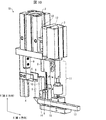
- FIG. 1 is a front view showing an example of a linear member gripping device according to the present embodiment.
- FIG. 2 is a side view showing an example of the linear member gripping device according to the present embodiment.
- linear member gripping device means a device that grips a plurality of linear members obtained after various processing and supplied as an aggregate one by one. Further, in the present embodiment, a lead wire as an electric wiring is assumed as the linear member, but any linear member may be used.
- the linear member gripping device 1A includes a first driving unit 2, a second driving unit 3, a first gripping member 4, a second gripping member 5, and a limiting unit 6.
- the first driving unit 2 changes the relative positions of the first gripping member 4 and the second gripping member 5 in the first direction, which is a direction toward or away from each other.
- the first direction is the direction perpendicular to the first gripping surface 4a and the second gripping surface 5a.
- the second driving unit 3 changes the relative positions of the first gripping member 4 and the second gripping member 5 in the second direction perpendicular to the first direction.
- the second direction is a direction parallel to the first gripping surface 4a and the second gripping surface 5a.
- the first gripping surface 4a and the second gripping surface 5a do not have to be arranged completely parallel to each other, and may face each other in a state of being deviated from parallel by a predetermined angle within an allowable range. Further, the first direction and the second direction do not have to be completely vertical, and may be an angle deviated from the vertical by a predetermined angle within an allowable range.
- each driving unit further drives each gripping member.
- one of the plurality of linear members can be gripped by the first gripping member 4, the second gripping member 5, and the limiting portion 6.
- FIG. 4 is an enlarged view showing the inside of the dotted line frame in FIG.
- the linear member gripping device 1A includes a first driving unit 2, a second driving unit 3, a first gripping member 4, a second gripping member 5, and a limiting unit 6.
- the first sliding portion 7 and the second sliding portion 8 are included.
- the first gripping member 4 has a first gripping surface 4a that abuts on a linear member to be gripped.
- the second gripping surface has a second gripping surface 5a facing the first gripping surface 4a, and has a protrusion 5b protruding from the second gripping surface 5a toward the first gripping surface 4a.
- the first gripping surface 4a is formed with a root side gripping surface 4b, a tip side gripping surface 4d, and a stepped surface 4c connecting the root side gripping surface 4b and the tip side gripping surface 4d in this order in the vertical downward direction. There is. Further, the distance A between the root side gripping surface 4b and the second gripping surface 5a is farther than the distance B between the tip side gripping surface 4d and the second gripping surface 5a.
- the first driving unit 2 changes the relative positions of the first gripping member 4 and the second gripping member 5 in the first direction X perpendicular to the first gripping surface 4a and the second gripping surface 5a.
- the second driving unit 3 changes the relative positions of the first gripping member 4 and the second gripping member 5 in the second direction Y parallel to the first gripping surface 4a and the second gripping surface 5a.
- the limiting unit 6 limits the movement of the linear member gripped between the first gripping member 4 and the second gripping member 5 in the second direction Y at a predetermined limiting position (described later).
- the first sliding portion 7 is a guide member for moving the relative position between the first gripping member 4 and the second gripping member 5 in the first direction X.
- the second sliding portion 8 is a guide member for moving the relative position between the first gripping member 4 and the second gripping member 5 in the second direction Y.
- FIG. 5 is a schematic view showing an example of the shape of the protrusion 5b of the linear member gripping device according to the present embodiment.
- reference numeral 101 in FIG. 5 when the linear member 50 comes into contact with the first gripping surface 4a and the protrusion 5b (projection surface 5c), the linear member 50 is formed from the center point C in the cross section 50a of the linear member 50.
- the angle ⁇ formed by the straight line from the center point C to the contact point D between the gripping surface 4a and the linear member 50 and the straight line from the center point C to the contact point E between the protrusion 5b (projection surface 5c) and the linear member 50 is
- the protrusion 5b has a shape larger than 90 degrees and smaller than 180 degrees.
- the shape of the protrusion 5b is not particularly limited as long as the angle ⁇ is larger than 90 degrees and smaller than 180 degrees.
- the cross-sectional shape of the protrusion may include a substantially partial circle, such as the protrusion (projection surface 5d) shown by reference numeral 102 in FIG.
- the shape such that the angle ⁇ can be 90 degrees or less for example, as in the protruding surfaces 5f and 5e, the normal direction of the surface is higher than the vertical direction.
- the shape of the protrusion is not limited unless the linear member 50 has a shape that may come into contact with the linear member 50 at a position on the protrusion surface that is inclined toward the gripping surface 5a. In consideration of the above relationship, the shape of the protrusion is appropriately determined according to the size of the major axis of the cross section 50a (or the type of the linear member 50).
- FIG. 6 is a schematic view showing an example of the shape of the stepped surface 4c of the linear member gripping device according to the present embodiment.
- reference numeral 201 in FIG. 6 when the linear member 50 comes into contact with the second gripping surface 5a and the stepped surface 4c, from the center point C in the cross section 50a of the linear member 50 to the second gripping surface 5a.
- the angle ⁇ formed by the straight line to the contact point F with the linear member 50 and the straight line from the center point C to the stepped surface 4c and the linear member 50 and the contact point G is larger than 90 degrees and smaller than 180 degrees.
- the stepped surface 4c has a shape.
- the shape of the stepped surface 4c is not particularly limited as long as the angle ⁇ is larger than 90 degrees and smaller than 180 degrees. ..
- the cross-sectional shape of the stepped surface may be a shape such as the stepped surface 4e shown by reference numeral 202 in FIG.
- the shape such that the angle ⁇ can be 90 degrees or less for example, the normal direction of the surface is the vertical direction such as the step surface 4g and the step surface 4f).
- the shape of the stepped surface is not limited unless the linear member 50 has a shape that may come into contact with the linear member 50 at a position on the stepped surface that is tilted toward the root side gripping surface 4b side.
- the shape of the stepped surface is appropriately determined according to the size of the major axis of the cross section 50a (or the type of the linear member 50).
- the first drive unit 2, the second drive unit 3, the first grip member 4, the second grip member 5, the first sliding portion 7, and the second sliding portion 8 are structural members (for example, structural members 9, 10). , 12, 14 and 15).
- the limiting portion 6 is provided, for example, on the root side of the root side gripping surface 4b of the first gripping member 4.
- FIG. 3 is a block diagram showing an example of a functional block of the control unit included in the linear member gripping device 1A.
- the linear member gripping device 1A includes the control unit 30.
- the control unit 30 includes a CPU (Central Processing Unit), a RAM (Random Access Memory), a ROM (Read Only Memory), and the like, and controls each component according to information processing.
- CPU Central Processing Unit
- RAM Random Access Memory
- ROM Read Only Memory
- the control unit 30 includes a detection unit 301, a recognition unit 302, and a drive control unit 303.
- the detection unit 301 is a functional block that detects the distance between the first gripping surface 4a and the second gripping surface 5a (or the protruding surface 5c) (for example, the distance A or the distance B in FIG. 4).
- the recognition unit 302 is a functional block that recognizes the number of linear members gripped by the first gripping surface 4a and the second gripping surface 5a based on the detected distance.
- the detection unit 301 and the recognition unit 302 may be provided in an external control device connected to the linear member gripping device 1A via a communication network. Examples of the external control device include PLC (Programmable Logic Controller) and IPC (Industrial PC).
- the drive control unit 303 is a functional block that drives the first drive unit 2 and the second drive unit 3.
- the drive control unit 303 controls the drive and stop of the first drive unit 2 and the second drive unit 3 according to the processing of the detection unit 301 and the recognition unit 302.
- FIG. 7 is a schematic view showing a series of operations of the linear member gripping device 1A according to the present embodiment.
- FIG. 7 illustrates only the configuration within the dotted line frame in FIG. Further, in FIG. 7, the horizontal direction which is the left-right direction toward the paper surface is defined as the first direction X, and the vertical direction which is the vertical direction toward the paper surface is defined as the second direction Y.
- a gripping force in the first direction X is applied to both gripping members by driving the first driving unit 2, so that the first gripping member
- the relative positions of the 4 and the second gripping member 5 are closer to each other.
- the second gripping member 5 is driven vertically upward by the second driving unit 3 so that the protruding portion 5b approaches the vicinity of the limiting portion 6 (hereinafter referred to as a limiting position) (reference numerals 402 and 403).
- the plurality of linear members gripped between the first gripping member 4 and the second gripping member 5 have a second gripping surface as the second gripping member 5 moves in the vertically upward direction. While rolling on 5a, it moves vertically upward. During the movement, the protrusion 5b restricts the linear member (cross section 50c) from moving vertically downward. As a result, the plurality of linear members are moved upward without releasing the plurality of linear members gripped by both gripping members.
- the linear member (cross section 50a) closest to the limiting portion 6 among the plurality of linear members arranged in a row comes into contact with the limiting portion 6. It reaches the vicinity of the surface 6a (restricted position).
- the drive control unit moves the second gripping member 5 upward so that the length of the second gripping surface is left so that one linear member is sandwiched between the gripping members. It will be stopped. Therefore, only one linear member is left between the two gripping members.
- the relative positions of the first gripping member 4 and the second gripping member 5 are moved vertically downward so that the protrusion 5b is separated from the restricted position.
- the second gripping member 5 is driven and returns to the original position before driving (the position of the second gripping member 5 shown by reference numeral 401) (reference numerals 406 and 407).
- the cross section 50a gripped between the two gripping members moves vertically downward while rolling on the second gripping surface 5a as the second gripping member 5 is driven in the second direction Y.
- the cross section 50a moved vertically downward comes into contact with the stepped surface 4c.
- the second driving unit 3 drives the relative positions of the first gripping member 4 and the second gripping member 5 in a direction away from the restricted position, and then grips the linear member (cross section 50a).
- the first gripping member 4 and the second gripping member 5 holding the linear member with respect to the first gripping member 4 and the second gripping member 5 are in the root side direction (upward direction) in the second direction Y. Driven to move to. By this movement, the linear member (cross section 50a) is pulled up to the upper part of the linear member gripping device 1A.
- FIG. 12 is a schematic view showing how one linear member 53 provided with the terminal member 53a is gripped according to an operation example of the linear member gripping device according to the present embodiment.
- the left side view of reference numerals 801 and 802 shows a side view of the first gripping member 4 as viewed from a direction perpendicular to the extending direction of the linear member when the linear member is gripped.
- the right side view of reference numerals 801 and 802 shows a front view of the first gripping member 4 and the second gripping member as viewed from the extending direction of the linear member when the linear member is gripped.
- the linear member gripping device 1A is linear with the protrusion surface 5g of the protrusion 5b and the contact surface 6a (not shown) of the restriction portion 6 as shown by reference numeral 802 in FIG.
- the member 53 is gripped.
- the linear member 53 can be gripped so as to be in a state parallel to the substantially horizontal direction.
- the left side view of reference numerals 501 to 503 shows a side view of the first gripping member 4 as viewed from a direction perpendicular to the extending direction of the linear member when the linear member is gripped.
- the right side view of reference numerals 501 to 503 shows a front view of the first gripping member 4 and the second gripping member as viewed from the extending direction of the linear member when the linear member is gripped.
- the linear member gripping device 1A can unentangle the linear members with each other by the following operations.
- the second gripping member 5 is driven in the vertically downward direction.
- the linear member 51 in contact with the second gripping surface 5a rotates and moves in the vertically downward direction.
- the movement causes the linear member 52 to rotate, and the terminal member 52a also rotates accordingly. Therefore, the terminal member 51a and the terminal member 52a are disengaged, and the linear member 51 and the linear member 52 are unentangled (reference numeral 503).
- the second gripping member 5 is driven vertically downward.
- the linear member 52 moves vertically downward, so that the linear member 52 is released from both gripping members (reference numeral 503).
- the number of linear members gripped by both gripping members is detected by the detection unit 301 detecting the distance between the first gripping surface 4a and the second gripping surface 5a. Based on the distance, the recognition unit 302 recognizes the number of linear members gripped by the first gripping surface 4a and the second gripping surface 5a.
- the recognition unit 302 recognizes the number of linear members gripped by the first gripping surface 4a and the second gripping surface 5a.
- FIG. 9 is a schematic view showing an example of a method for detecting the number of linear members in the operation example of the linear member gripping device 1A according to the present embodiment.
- the detection unit 301 determines the distance I between the first gripping surface 4a and the second gripping surface 5a or the distances H, J and K between the first gripping surface 4a and the protruding surface 5c. To detect.
- the recognition unit 302 Based on the distance detected by the detection unit 301, the recognition unit 302 recognizes the number of linear members gripped by the first grip surface 4a and the second grip surface 5a (projection surface 5c). For example, when the detection unit 301 detects that the distance is H, the recognition unit 302 recognizes that two linear members are gripped. Further, for example, when the detection unit 301 detects that the distance is I or J, the recognition unit 302 recognizes that one linear member is being gripped. Further, for example, when the detection unit 301 detects that the distance is K, the recognition unit 302 recognizes that no linear member is gripped. The success / failure of the gripping operation is determined according to the number of linear members recognized by the recognition unit 302, the linear member is conveyed in the case of success, and the gripping operation is performed again in the case of failure. Is performed, and so on.
- the device that enables the detection unit 301 to detect each distance is not particularly limited.
- Examples thereof include a configuration in which the cylinder sensor output and the like are transmitted to the detection unit 301.
- the recognition unit 302 recognizes the number of linear members held based on the distance detected by the detection unit 301, but from a sensor capable of directly detecting the number of linear members.
- the output of may be used.
- the sensing result by the proximity sensor, the photoelectric sensor, or the like may be transmitted to the recognition unit 302, and the recognition unit 302 may directly recognize the number of linear members from the sensing result.
- FIG. 10 is a side view showing another example of the linear member gripping device according to the present embodiment.
- the linear member gripping device 1B may be provided with the insertion member 17 as shown in FIG.
- FIG. 11 is a schematic view showing another example of a series of flows of the operation of the linear member gripping device 1B according to the present embodiment.
- the horizontal direction is defined as the first direction X
- the vertical vertical direction is defined as the second direction Y.
- the operations shown by reference numerals 701 to 707 in FIG. 11 are shown by reference numerals 401 to 407 in FIG. Since it is the same as the operation, the description thereof is omitted here.
- the second gripping member 5 is driven in a direction away from the restricted position. Then, after the protrusion 5b is driven in the direction away from the restricted position, the second gripping member 5 is driven in the vertically downward direction. That is, the second driving unit 3 drives the relative positions of the first gripping member 4 and the second gripping member 5 in the direction in which the protrusion 5b is separated from the restricted position.
- the insertion member 17 is inserted at a predetermined position on the root side (upward direction) of the protrusion 5b at the time after driving (reference numeral 708).
- the second driving unit 3 lifts the first gripping member 4 and the second gripping member 5 in the vertically upward direction, and moves one gripping linear member to the place of the next step. (Reference numeral 709).
- the second gripping member 5 is driven in the second direction Y, but the driving method of the first gripping member 4 and the second gripping member 5 is not limited to this. ..
- the second gripping member 5 is fixed and the first gripping member 4 is driven in the second direction Y, so that one linear member is gripped from the plurality of linear members. You may be broken. Further, by driving the first gripping member and the second gripping member in the second direction Y, respectively, an operation may be performed in which one linear member is gripped from the plurality of linear members.
- ⁇ 2 and ⁇ 4 an operation example of gripping a plurality of linear members by being driven so that the first gripping member 4 and the second gripping member 5 approach each other in the first direction X is shown.
- the method of driving the first gripping member 4 and the second gripping member 5 is not limited to this.
- the first gripping member 4 may be fixed and only the second gripping member 5 may be driven in the first direction X to perform an operation in which a plurality of linear members are gripped.
- the second gripping member 5 may be fixed and only the second gripping member 5 may be driven in the first direction X to perform an operation in which a plurality of linear members are gripped.
- ⁇ 2 and ⁇ 4 an operation example in which one linear member is left from a plurality of linear members by driving the second gripping member 5 in the second direction Y has been described.
- the direction driven to release the plurality of linear members from is not limited to the second direction.
- the linear member gripping device shown in FIG. 2 and the like is provided so that the first gripping member and the second gripping member extend vertically in the vertical direction.
- the first gripping member and the second gripping member may be provided so as to extend in the horizontal direction so that a plurality of linear members are released from both gripping members in the first direction X.
- the linear member gripping device has a first gripping member having a first gripping surface that abuts on the linear member as a gripping object, and a linear member that abuts on the linear member and touches the first gripping surface.
- a second gripping member having a second gripping surface facing each other and having a protrusion protruding from the second gripping surface toward the first gripping surface, and a relative position between the first gripping member and the second gripping member.
- a first driving unit that changes in a first direction that is a direction toward or away from each other, a second driving unit that changes in a second direction that is a direction perpendicular to the first direction, and the first gripping member. It is provided with a limiting portion that limits the movement of the linear member sandwiched between the second gripping member in the second direction at a predetermined limiting position.
- each driving unit further drives each gripping member.
- one of the plurality of linear members can be gripped by the first gripping member, the second gripping member, and the limiting portion. Therefore, a device capable of reliably gripping only one linear member is realized.
- the second driving unit Drives the relative positions of the first gripping member and the second gripping member so that the protrusion approaches the limiting position.
- the first gripping member is such that the number of the plurality of gripped linear members is reduced and only one linear member sandwiched between the first gripping member and the second gripping member is left. And the second gripping member can be driven.
- the protrusion limits the position. Drive in the direction away from the position.
- the distance between the linear member gripped by the first gripping member and the second gripping member and the other linear member that is not gripped can be separated.
- the first gripping surface has a root side gripping surface, a tip side gripping surface, and a stepped surface connecting the root side gripping surface and the tip end side gripping surface.
- the distance between the root-side gripping surface and the second gripping surface is longer than the distance between the tip-side gripping surface and the second gripping surface.
- the linear member can be fitted to the stepped surface and the second gripping surface, so that the movement of the linear member can be restricted.
- the linear member gripping device is such that when the linear member comes into contact with the first gripping surface and the protrusion, the first gripping surface is viewed from a central point in the cross section of the linear member.
- the angle formed by the straight line to the contact point between the linear member and the linear member and the straight line from the center point to the contact point between the protrusion and the linear member is larger than 90 degrees and smaller than 180 degrees.
- the movement of the linear member due to the movement of the linear member can be restricted.
- the contact point between the second gripping surface and the linear member from the center point in the cross section of the linear member when the linear member comes into contact with the second gripping surface and the stepped surface, the contact point between the second gripping surface and the linear member from the center point in the cross section of the linear member.
- the angle formed by the straight line to the center point and the straight line from the center point to the stepped surface, the linear member, and the contact point is larger than 90 degrees and smaller than 180 degrees.
- the movement of the linear member due to the movement of the linear member can be restricted.
- the second driving unit grips the linear member after driving the relative positions of the first gripping member and the second gripping member in a direction in which the protrusions move away from the restricted position.
- the first gripping member and the second gripping member move in the direction toward the root side in the second direction.
- the linear member gripped by the first gripping member and the second gripping member can be pulled up from the linear member gripping device.
- the second driving unit drives the relative positions of the first gripping member and the second gripping member in a direction in which the protrusions move away from the restricted position, the protrusions at that time.
- An insertion member to be inserted at a predetermined position on the root side of the portion is further provided.
- a recognition unit that recognizes the number of the linear members gripped by the first gripping surface and the second gripping surface is further provided.
- the recognition unit detects the distance between the first gripping surface and the second gripping surface, and recognizes the number of the linear members based on the detected distance.
- the number of linear members can be recognized based on the relatively easy-to-detect detection target of the distance between the first gripping surface and the second gripping surface.
Landscapes
- Engineering & Computer Science (AREA)
- Mechanical Engineering (AREA)
- Robotics (AREA)
- Manufacturing & Machinery (AREA)
- Health & Medical Sciences (AREA)
- General Health & Medical Sciences (AREA)
- Orthopedic Medicine & Surgery (AREA)
- Manipulator (AREA)
- Wire Processing (AREA)
Abstract
線状部材を確実に1本だけ把持することができる装置を実現する。線状部材に当接する第1把持部材(4)と、前記線状部材に当接し、突起部を有する第2把持部材(5)と、前記第1把持部材と前記第2把持部材との相対位置を変化させる第1駆動部(2)および第2駆動部(3)と、前記第1把持部材と前記第2把持部材とに挟まれる前記線状部材の移動を所定の制限位置で制限する制限部(6)とを備える。
Description
本発明は線状部材把持装置に関する。
各種工程後に得られたリード線等の線状部材は集められ、線状部材の集合体が形成される。その後、該集合体から線状部材が1本ずつ分離されて、後の処理工程へ、分離後の線状部材が順次供給される。
線状部材の集合体から、線状部材を1本ずつ分離するための技術として、例えば、特許文献1には、線材を収容する収容部と、該線材を把持して移動させる把持部と、該収容部を変位させる可動部と、を含み、前記収容部は、前記線材を境に向かい合う第1収容片および第2収容片を有し、それら両収容片の乖離間隔を、一方向側に近づけるほど短くするようにし、かつ、その一方向側に開口を有しており、前記把持部は、向かい合う第1把持片および第2把持片を有し、それら両把持片の乖離間隔を、一方向側に近づけるほど短くさせて、その乖離間隔に、前記開口から露出する前記線材を収めることで把持し、前記可動部は、前記把持部から前記開口を乖離させるように、前記収容部を変位させる、線材供給装置が開示される。
上述の従来技術は、前記把持部を前記開口へ向かって移動させ、前記把持部の両把持片の乖離間隔の間に、線材を挟ませるものである。前記両把持片の乖離間隔が、両把持片の根元に近い側に向かって短くなり、両把持片の根元と反対側に向かって長くなる構造を、前記把持部は有する。前記両把持片が該構造を有することにより、前記収容部に収められ、前記開口から露出した複数の線材のうち、前記両把持片の乖離間隔に1本だけの線材を把持できず、複数本の線材が把持される虞がある。それ故、線材を確実に1本だけ把持することができる装置が求められていた。
本発明の一態様は、線状部材を確実に1本だけ把持することができる装置を実現する。
本発明の一態様は、線状部材を確実に1本だけ把持することができる装置を実現する。
前記の課題を解決するために、本発明の一態様に係る線状部材把持装置は、把持対象としての線状部材に当接する第1把持面を有する第1把持部材と、前記線状部材に当接し、前記第1把持面に対向する第2把持面を有するとともに、前記第2把持面から前記第1把持面側に突出する突起部を有する第2把持部材と、前記第1把持部材と前記第2把持部材との相対位置を、互いに近づくまたは遠ざかる方向である第1方向に変化させる第1駆動部、および、前記第1方向に垂直な方向である第2方向に変化させる第2駆動部と、前記第1把持部材と前記第2把持部材とに挟まれる前記線状部材の前記第2方向への移動を所定の制限位置で制限する制限部とを備える。
本発明の一態様によれば、線状部材を確実に1本だけ把持することができる装置を実現する。
以下、本発明の一側面に係る実施の形態(以下、「本実施形態」とも表記する)を、図面に基づいて説明する。
§1 適用例
図1および2を用いて、本発明が適用される場面の線状部材把持装置について説明する。図1は、本実施形態における線状部材把持装置の一例を示した正面図である。図2は、本実施形態における線状部材把持装置の一例を示した側面図である。
図1および2を用いて、本発明が適用される場面の線状部材把持装置について説明する。図1は、本実施形態における線状部材把持装置の一例を示した正面図である。図2は、本実施形態における線状部材把持装置の一例を示した側面図である。
本明細書において、「線状部材把持装置」とは、各種加工後に得られ、集合体として供給された複数の線状部材を、1本ずつ把持する装置を意味する。また、本実施形態では、線状部材として、電気配線としてのリード線を想定しているが、各種線状の部材であればどのようなものであってもよい。
本実施形態に係る線状部材把持装置について、図1および図2に基づいて説明すれば以下のとおりである。本実施形態に係る線状部材把持装置1Aは、第1駆動部2、第2駆動部3、第1把持部材4、第2把持部材5および制限部6を含む。
第1把持部材4および第2把持部材5は、前記線状部材に当接し、線状部材を把持する。図4に示すように、第1駆動部2は、第1把持部材4と第2把持部材5との相対位置を、互いに近づくまたは遠ざかる方向である第1方向に変化させる。この例では、第1方向は、第1把持面4aおよび第2把持面5aに垂直な方向となる。また、第2駆動部3は、第1把持部材4と第2把持部材5との相対位置を、第1方向に垂直な第2方向に変化させる。この例では、第2方向は、第1把持面4aおよび第2把持面5aに平行な方向となる。なお、第1把持面4aおよび第2把持面5aは、互いに完全に平行に配置されている必要はなく、許容される範囲で平行から所定の角度ずれた状態で互いに対向していてもよい。また、第1方向と第2方向とは、完全に垂直でなくてもよく、許容される範囲で垂直から所定の角度ずれた角度であってもよい。
第1駆動部2および第2駆動部3により駆動された第1把持部材4および第2把持部材5が複数の線状部材を把持した後、さらに各駆動部により各把持部材が駆動されることにより、複数の線状部材のうちの、1本の線状部材を、第1把持部材4、第2把持部材5および制限部6で把持することができる。
§2 構成例
〔線状部材把持装置の構成例〕
図1、図2および図4を用いて、本実施形態に係る線状部材把持装置の一例について説明する。ここで、図4は、図1における点線枠内を示す拡大図である。
〔線状部材把持装置の構成例〕
図1、図2および図4を用いて、本実施形態に係る線状部材把持装置の一例について説明する。ここで、図4は、図1における点線枠内を示す拡大図である。
図1および図2の例では、本実施形態に係る線状部材把持装置1Aは、第1駆動部2、第2駆動部3、第1把持部材4、第2把持部材5、制限部6、第1摺動部7および第2摺動部8を含む。
第1把持部材4は、把持対象としての線状部材に当接する第1把持面4aを有する。第2把持面は、第1把持面4aに対向する第2把持面5aを有し、第2把持面5aから第1把持面4a側に突出する突起部5bを有する。
第1把持面4aは、鉛直下方向に向かって順に、根元側把持面4b、先端側把持面4dおよび、根元側把持面4bと先端側把持面4dとを接続する段差面4cが形成されている。また、根元側把持面4bと第2把持面5aとの距離Aが、先端側把持面4dと第2把持面5aとの距離Bよりも遠い。
第1駆動部2は、第1把持部材4と第2把持部材5との相対位置を、第1把持面4aおよび第2把持面5aに垂直な第1方向Xに変化させる。第2駆動部3は、第1把持部材4と第2把持部材5との相対位置を、第1把持面4aおよび第2把持面5aに平行な第2方向Yに変化させる。
制限部6は、第1把持部材4と第2把持部材5との間に把持された線状部材の第2方向Yへの移動を、所定の制限位置(後述)で制限する。
第1摺動部7は、第1把持部材4と第2把持部材5との相対位置を第1方向Xへ移動させるためのガイド部材である。第2摺動部8は、第1把持部材4と第2把持部材5との相対位置を第2方向Yへ移動させるためのガイド部材である。
ここで、突起部5bの形状について以下に説明する。図5は、本実施形態における線状部材把持装置の、突起部5bの形状の例を示す概略図である。図5の符号101に示すように、線状部材50が第1把持面4aと突起部5b(突起面5c)とに接触する場合に、線状部材50の断面50aにおける中心点Cから、第1把持面4aと線状部材50との接点Dへの直線と、中心点Cから、突起部5b(突起面5c)と線状部材50との接点Eへの直線とがなす角度αが、90度より大きく、180度よりも小さくなる形状を、突起部5bは有する。
線状部材50が第1把持面4aと突起部5bとに接触する場合に、角度αが90度より大きく、180度よりも小さくなる形状であれば、突起部5bの形状は特に限定されない。突起部5bの形状の例として、例えば、図5の符号102に示す突起部(突起面5d)のように、突起部の断面形状が略部分円を含むような形状であってもよい。換言すれば、図5の符号103および104に示すような、角度αが90度以下となり得るような形状(例えば、突起面5fおよび5eのように、面の法線方向が鉛直方向よりも第2把持面5a側に傾いているような突起面上の位置で線状部材50が接触する可能性があるような形状)でなければ、突起部の形状は限定されない。以上の関係を考慮して、突起部の形状は、断面50aの長径の大きさ(または、線状部材50の種類)に応じて適宜決定される。
また、段差面4cの形状について以下に説明する。図6は、本実施形態における線状部材把持装置の、段差面4cの形状の例を示す概略図である。図6の符号201に示すように、線状部材50が第2把持面5aと段差面4cとに接触する場合に、線状部材50の断面50aにおける中心点Cから、第2把持面5aと線状部材50との接点Fへの直線と、中心点Cから、段差面4cと線状部材50と接点Gへの直線とがなす角度βが、90度より大きく、180度よりも小さくなる形状を、段差面4cは有する。
線状部材50が第2把持面5aと段差面4cとに接触する場合に、角度βが、90度より大きく、180度よりも小さくなる形状であれば、段差面4cの形状は特に限定されない。段差面4cの形状の例として、例えば、図6の符号202に示す段差面4eのように、段差面の断面形状が弧を描くような形状であってもよい。換言すれば、図6の符号203や符号204に示すような、角度βが90度以下となり得るような形状(例えば、段差面4gや段差面4fのように、面の法線方向が鉛直方向よりも根元側把持面4b側に傾いているような段差面上の位置で線状部材50が接触する可能性があるような形状)でなければ、段差面の形状は限定されない。以上の関係を考慮して、段差面の形状は、断面50aの長径の大きさ(または、線状部材50の種類)に応じて適宜決定される。
第1駆動部2、第2駆動部3、第1把持部材4、第2把持部材5、第1摺動部7および第2摺動部8は、各構造部材(例えば、構造部材9、10、12、14および15)を介して接続される。制限部6は、例えば、第1把持部材4における根元側把持面4bのさらに根元側に設けられる。
〔線状部材把持装置に含まれる制御部の、機能ブロックの例〕
図3を用いて、本実施形態に係る線状部材把持装置に含まれる制御部の、機能ブロックの一例について説明する。図3は、線状部材把持装置1Aに含まれる制御部の、機能ブロックの一例を示すブロック図である。
図3を用いて、本実施形態に係る線状部材把持装置に含まれる制御部の、機能ブロックの一例について説明する。図3は、線状部材把持装置1Aに含まれる制御部の、機能ブロックの一例を示すブロック図である。
図3の例では、本実施形態に係る線状部材把持装置1Aは、制御部30を含む。制御部30は、CPU(Central Processing Unit)、RAM(Random Access Memory)、ROM(Read Only Memory)等を含み、情報処理に応じて各構成要素の制御を行う。
制御部30は、検出部301、認識部302および駆動制御部303を含む。検出部301は、第1把持面4aと第2把持面5a(または突起面5c)との距離(例えば、図4における距離Aまたは距離B)を検出する機能ブロックである。認識部302は、検出された前記距離に基づいて、第1把持面4aと第2把持面5aとによって把持されている線状部材の数を認識する機能ブロックである。なお、検出部301および認識部302は、線状部材把持装置1Aと通信ネットワークを介して接続される外部の制御装置に設けられる構成としてもよい。外部の制御装置としては、例えばPLC(Programmable Logic Controller)やIPC(Industrial PC)などが挙げられる。
駆動制御部303は、第1駆動部2および第2駆動部3を駆動させる機能ブロックである。駆動制御部303は、検出部301および認識部302の処理に応じて、第1駆動部2および第2駆動部3の駆動および停止を制御する。
§3 動作例
図7を用いて、本実施形態に係る線状部材把持装置の動作例を説明する。図7は、本実施形態に係る線状部材把持装置1Aの動作の一連の流れを示す概略図である。なお、説明の便宜上、図7は図1における点線枠内の構成のみを図示している。また、図7において、紙面向かって左右方向となる水平方向を第1方向X、紙面向かって上下方向となる鉛直方向を第2方向Yとする。
図7を用いて、本実施形態に係る線状部材把持装置の動作例を説明する。図7は、本実施形態に係る線状部材把持装置1Aの動作の一連の流れを示す概略図である。なお、説明の便宜上、図7は図1における点線枠内の構成のみを図示している。また、図7において、紙面向かって左右方向となる水平方向を第1方向X、紙面向かって上下方向となる鉛直方向を第2方向Yとする。
まず、各種加工後に得られ、複数の線状部材が集められる。集められた線状部材が線状部材把持装置1Aに供給されると、第1把持部材4と第2把持部材5との相対位置を互いに近づけるように、第1把持部材4および第2把持部材5が第1方向Xへ、第1駆動部2により駆動される。これにより、複数本の線状部材(断面50a、50bおよび50c)が把持される(符号401)。
前記複数本の線状部材が両把持部材により把持されると、両把持部材に対して、第1方向Xへの把持力が第1駆動部2の駆動により加えられることにより、第1把持部材4と第2把持部材5との相対位置が互いにさらに近づく。また、突起部5bが制限部6付近(以降、制限位置と称する)に近づくように、第2駆動部3により第2把持部材5が鉛直上方向へ駆動される(符号402、403)。第1把持部材4と第2把持部材5との間で複数本の線状部材が摺り合わされることで、該複数本の線状部材が、第2方向Yに向かって一列に整列される。また、第1把持部材4と第2把持部材5との間で把持された、該複数本の線状部材は、第2把持部材5の、鉛直上方向への移動に伴い、第2把持面5a上を転がりながら、鉛直上方向へ移動する。該移動の際、突起部5bにより線状部材(断面50c)が、鉛直下方向への移動が制限される。これにより、両把持部材に把持された複数本の線状部材が放されることなく、複数本の線状部材は上方向へ移動する。
複数本の線状部材が上方向へ移動し続けると、一列に並んだ複数の線状部材のうち、制限部6に最も接近している線状部材(断面50a)が制限部6の当接面6a付近(制限位置)へ到達する。鉛直上方向へ駆動された第2把持部材5への、第2方向Yへの移動と、第1把持部材4および第2把持部材5との、第1方向Xに向かって生じる把持力とのバランスとにより、両把持部材の間隔が開き、線状部材(断面50bおよび50c)が、鉛直下方向へ向かって、1本ずつ両把持部材から放される(符号404、405)。このとき、線状部材1本分が両把持部材の間に挟まる程度の、第2把持面の長さを残すようにして、第2把持部材5の上方向への移動が、駆動制御部より停止される。このため、両把持部材の間には、線状部材が1本だけ残される。
両把持部材の間に、線状部材が1本だけ残された後、突起部5bが前記制限位置から離れるように、鉛直下方向へ第1把持部材4および第2把持部材5の相対位置を駆動する。具体的に、第2把持部材5が駆動され、駆動前の元の位置(符号401に示す、第2把持部材5の位置)に戻る(符号406、407)。このとき、両把持部材の間に把持された断面50aは、第2把持部材5の第2方向Yへの駆動に伴い、第2把持面5a上を転がりながら、鉛直下方向へ移動する。鉛直下方向へ移動した断面50aは、段差面4cと接する。段差面4c、根元側把持面4bおよび第2把持面5aに線状部材(断面50a)が嵌合することにより、断面50aの、鉛直下方向への移動が制限される。
第2駆動部3が、第1把持部材4および第2把持部材5との相対位置を、突起部5bが前記制限位置から離れる方向に駆動した後に、線状部材(断面50a)を把持している第1把持部材4と第2把持部材5とを、前記線状部材を把持している第1把持部材4および第2把持部材5が、第2方向Yにおける根元側の方向(上方向)へ移動するように駆動される。この移動により、線状部材(断面50a)が線状部材把持装置1Aの上部へ引き上げられる。
なお、符号401から符号407迄の一連の動作で、基本的には線状部材は1本だけ把持された状態になるが、線状部材が2本以上残る可能性が0ではない状況もありうる。この場合、例えば符号403から符号407のステップを2回実行するようにすれば、線状部材が2本以上残る可能性をほぼ0にすることができる。
以下に、図12を用いて、本実施形態に係る動作例による、1本の線状部材が把持される様子の例を説明する。図12は、本実施形態に係る線状部材把持装置の動作例による、端子部材53aが設けられている1本の線状部材53が把持される様子を示す概略図である。なお、符号801および802の、左側の図は、線状部材を把持しているときの、線状部材の延伸方向に垂直な方向から見た第1把持部材4の側面図を示す。また、符号801および802の、右側の図は、線状部材を把持しているときの、線状部材の延伸方向から見た第1把持部材4および第2把持部材の正面図を示す。
図12の符号801に示すように、まず、1本の線状部材53を第1把持部材4および第2把持部材5とで左右方向から挟むことにより、線状部材53の左右方向の傾きをなくす。1本の線状部材53を第1把持部材4および第2把持部材5とで挟んだ後、図12の符号802に示すように、挟んだ線状部材53が制限部6(不図示)まで持ち上げられることにより、線状部材53の上下方向の傾きをなくす。
図12の符号801に示すように、まず、1本の線状部材53を第1把持部材4および第2把持部材5とで左右方向から挟むことにより、線状部材53の左右方向の傾きをなくす。1本の線状部材53を第1把持部材4および第2把持部材5とで挟んだ後、図12の符号802に示すように、挟んだ線状部材53が制限部6(不図示)まで持ち上げられることにより、線状部材53の上下方向の傾きをなくす。
ここで、本実施形態に係る線状部材把持装置1Aは、図12の符号802に示すように、突起部5bの突起面5gおよび制限部6の当接面6a(不図示)とで線状部材53を把持する。これにより、線状部材53を略水平方向と平行の状態になるように把持できる。
また、図8を用いて、本実施形態に係る動作例による、1本の線状部材が把持される様子の例を以下に説明する。なお、符号501から503の、左側の図は、線状部材を把持しているときの、線状部材の延伸方向に垂直な方向から見た第1把持部材4の側面図を示す。また、符号501から503の、右側の図は、線状部材を把持しているときの、線状部材の延伸方向から見た第1把持部材4および第2把持部材の正面図を示す。
把持対象の線状部材の端部に、例えば図8に示されるような各種部材(例えば、端子部材51aおよび52a等)が接続されている場合、符号501に示すように該部材同士が引っかかることにより、線状部材同士が絡まることがある。
これに対して、本実施形態に係る線状部材把持装置1Aは、以下のような動作により、上記の線状部材同士の絡みをほどくことができる。まず符号502に示すように、第2把持部材5が鉛直下方向へ駆動される。第2把持部材5の鉛直下方向への移動に伴い、第2把持面5aと接触している線状部材51が鉛直下方向へ回転し移動する。また、該移動により、線状部材52も回転し、それに伴い端子部材52aも回転する。そのため、端子部材51aと端子部材52aとの引っかかりが外れ、線状部材51と線状部材52との絡まりがほどかれる(符号503)。
その後、第2把持部材5が鉛直下方向へ駆動される。第2把持部材5の駆動に伴い、線状部材52が鉛直下方向へ移動することにより、線状部材52が両把持部材から放される(符号503)。
なお、図7に示す動作例において、符号401から符号405迄の一連の動作で、両把持部材の間に、線状部材が1本も残らなかった場合も、符号401から符号405迄の一連の動作が再度行われることにより、両把持部材の間に、線状部材を1本のみ残すことができる。
符号401から符号405迄の一連の動作で、両把持部材に把持された線状部材の本数は、第1把持面4aと第2把持面5aとの距離を検出部301が検出し、検出された前記距離に基づいて、認識部302が第1把持面4aと第2把持面5aとによって把持されている線状部材の数を認識する。ここで、本実施形態に係る線状部材把持装置の動作例における、線状部材の本数の検出方法と、線状部材の数の認識の一例を、以下に説明する。
図9は、本実施形態に係る線状部材把持装置1Aの動作例における、線状部材の本数の検出方法の一例を示す概略図である。図9の符号601から604に示す通り、第1把持面4aと第2把持面5aとの距離Iまたは第1把持面4aと突起面5cとの距離H、JおよびKを、検出部301が検出する。
検出部301により検出された距離に基づいて、第1把持面4aと第2把持面5a(突起面5c)によって把持されている線状部材の数を、認識部302が認識する。例えば距離Hであることが検出部301によって検出された場合、認識部302は、線状部材が2本把持されている状態であると認識する。また、例えば距離Iまたは距離Jであることが検出部301によって検出された場合、認識部302は、線状部材が1本把持されている状態であると認識する。また、例えば距離Kであることが検出部301によって検出された場合、認識部302は、線状部材が1本も把持されていない状態であると認識する。認識部302により認識された線状部材の数に応じて、把持動作の成功/失敗が判断され、成功の場合には線状部材の搬送動作が行われ、失敗の場合には再度の把持動作を行う、などの制御が行われる。
検出部301による各距離の検出を可能にする装置は特に限定されない。例えば、近接センサや光線センサなどによるセンシング結果が検出部301に送信される構成、および、第1把持部材4および第2把持部材5とのX方向の相対位置を変更させる駆動モータのエンコーダ出力やシリンダセンサ出力などが検出部301に送信される構成などが挙げられる。
また、上記の例では、認識部302は、検出部301によって検出された距離に基づいて把持されている線状部材の本数を認識しているが、線状部材の本数を直接検出できるセンサからの出力を用いてもよい。例えば、近接センサや光電センサなどによるセンシング結果が認識部302に送信され、認識部302がセンシング結果から直接線状部材の本数を認識してもよい。
§4 変形例
以上、本発明の実施の形態を詳細に説明してきたが、前述までの説明はあらゆる点において本発明の例示に過ぎない。本発明の範囲を逸脱することなく種々の改良や変形を行うことができることは言うまでもない。例えば、以下のような変更が可能である。なお、以下では、前記実施形態と同様の構成要素に関しては同様の符号を用い、前記実施形態と同様の点については、適宜説明を省略する。以下の変形例は適宜組み合わせ可能である。
以上、本発明の実施の形態を詳細に説明してきたが、前述までの説明はあらゆる点において本発明の例示に過ぎない。本発明の範囲を逸脱することなく種々の改良や変形を行うことができることは言うまでもない。例えば、以下のような変更が可能である。なお、以下では、前記実施形態と同様の構成要素に関しては同様の符号を用い、前記実施形態と同様の点については、適宜説明を省略する。以下の変形例は適宜組み合わせ可能である。
図10は、本実施形態に係る線状部材把持装置の他の例を示した側面図である。§2で説明した線状部材把持装置1Aに備えられる構成に加えて、線状部材把持装置1Bでは、図10のように、挿入部材17が備えられていてもよい。
以下、図11を用いて、挿入部材17が備えられている線状部材把持装置1Bの動作の例を説明する。図11は、本実施形態に係る線状部材把持装置1Bの動作の、一連の流れの他の例を示す概略図である。ここで、図11において、水平方向を第1方向X、鉛直上下方向を第2方向Yとする。
集められた線状部材が線状部材把持装置1Bに供給された後の動作例のうち、図11の符号701から707迄に示される動作は、図7に示す符号401から407迄に示される動作と同一であるため、ここでは説明を省略する。図11の符号706等に示されるように、制限位置から離れる方向に第2把持部材5が駆動される。その後、突起部5bが制限位置から離れる方向に駆動した後に、第2把持部材5が鉛直下方向へ駆動される。即ち、第2駆動部3が、第1把持部材4および第2把持部材5との相対位置を、突起部5bが制限位置から離れる方向に駆動する。その後、駆動後の時点での突起部5bよりも根元側(上方向)の所定位置に、挿入部材17が挿入される(符号708)。その後、第2駆動部3が、第1把持部材4および第2把持部材5を鉛直上方向へ持ち上げて、把持している1本の線状部材を次の工程の場所へ移動させる。(符号709)。
ここで、50aで示される線状部材(把持対象の線状部材)と50bで示される線状部材(把持対象ではない線状部材)とが絡み合っている場合、挿入部材17が挿入されない場合には、符号709のステップにおいて、50bで示される線状部材も持ち上げられて移動させられてしまうケースが考えられる。これに対して、上記のように挿入部材17が所定位置に挿入されることにより、把持対象ではない線状部材が把持対象の線状部材とともに持ち上げられて移動させられてしまうことを防ぐことができる。
なお、§2および§4において、第2方向Yへ、第2把持部材5が駆動された例を示したが、第1把持部材4および第2把持部材5の駆動の仕方はこれに限定されない。例えば、第2把持部材5が固定されて、第1把持部材4が第2方向Yへ駆動されることにより、複数の線状部材から1本の線状部材が把持されるような動作が行われてもよい。また、第1把持部材および第2把持部材がそれぞれ第2方向Yへ駆動されることにより、複数の線状部材から1本の線状部材が把持されるような動作が行われてもよい。
また、§2および§4において、第1方向Xへ、第1把持部材4および第2把持部材5が互いに接近するように駆動されることにより、複数の線状部材を把持する動作例を示したが、第1把持部材4および第2把持部材5の駆動の仕方はこれに限定されない。例えば、第1把持部材4が固定されて、第2把持部材5のみが第1方向Xへ駆動されることにより、複数の線状部材が把持されるような動作が行われてもよい。また、第2把持部材5が固定されて、第2把持部材5のみが第1方向Xへ駆動されることにより、複数の線状部材が把持されるような動作が行われてもよい。
さらに、§2および§4において、第2把持部材5が第2方向Yへ駆動されることにより、複数の線状部材から1本の線状部材を残す動作例を説明したが、両把持部材から複数の線状部材を放すために駆動される方向は、第2方向に限定されない。具体的に、図2等に示す線状部材把持装置は、第1把持部材および第2把持部材が鉛直上下方向に延伸するように設けられている。これに対し、第1方向Xに複数の線状部材が両把持部材から放されるように、第1把持部材および第2把持部材が水平方向に延伸するように設けられていてもよい。
〔まとめ〕
本発明の一態様に係る線状部材把持装置は、把持対象としての線状部材に当接する第1把持面を有する第1把持部材と、前記線状部材に当接し、前記第1把持面に対向する第2把持面を有するとともに、前記第2把持面から前記第1把持面側に突出する突起部を有する第2把持部材と、前記第1把持部材と前記第2把持部材との相対位置を、互いに近づくまたは遠ざかる方向である第1方向に変化させる第1駆動部、および、前記第1方向に垂直な方向である第2方向に変化させる第2駆動部と、前記第1把持部材と前記第2把持部材とに挟まれる前記線状部材の前記第2方向への移動を所定の制限位置で制限する制限部とを備える。
本発明の一態様に係る線状部材把持装置は、把持対象としての線状部材に当接する第1把持面を有する第1把持部材と、前記線状部材に当接し、前記第1把持面に対向する第2把持面を有するとともに、前記第2把持面から前記第1把持面側に突出する突起部を有する第2把持部材と、前記第1把持部材と前記第2把持部材との相対位置を、互いに近づくまたは遠ざかる方向である第1方向に変化させる第1駆動部、および、前記第1方向に垂直な方向である第2方向に変化させる第2駆動部と、前記第1把持部材と前記第2把持部材とに挟まれる前記線状部材の前記第2方向への移動を所定の制限位置で制限する制限部とを備える。
前記構成によれば、第1駆動部および第2駆動部により駆動された第1把持部材および第2把持部材が複数の線状部材を把持した後、さらに各駆動部により各把持部材が駆動されることにより、複数の線状部材のうちの、1本の線状部材を、第1把持部材、第2把持部材および制限部で把持することができる。それ故、線状部材を確実に1本だけ把持することができる装置を実現する。
一実施形態において、前記線状部材把持装置は、前記第1駆動部が、前記第1把持部材および前記第2把持部材との相対位置を、互いに近づけるように駆動した後に、前記第2駆動部が、前記第1把持部材および前記第2把持部材との相対位置を、前記突起部が前記制限位置に近づくように駆動する。
前記構成によれば、把持された複数の線状部材の数を減少させて、第1把持部材と第2把持部材とに挟まれる線状部材を1本だけ残すように、前記第1把持部材および前記第2把持部材を駆動できる。
一実施形態において、前記第2駆動部が、前記第1把持部材および前記第2把持部材との相対位置を、前記突起部が前記制限位置に近づくように駆動した後に、前記突起部が前記制限位置から離れる方向に駆動する。
前記構成によれば、第1把持部材と第2把持部材とで把持している線状部材と、把持されていない他の線状部材との距離を離すことができる。
一実施形態において、前記線状部材把持装置は、前記第1把持面は、根元側把持面、先端側把持面、および、前記根元側把持面と前記先端側把持面とを接続する段差面を備え、前記根元側把持面と前記第2把持面との距離が、前記先端側把持面と前記第2把持面との距離よりも遠い。
前記構成によれば、第1把持面が段差面を有することにより、段差面および第2把持面に線状部材が嵌合することにより、線状部材の移動を制限できる。
一実施形態において、前記線状部材把持装置は、前記線状部材が前記第1把持面と前記突起部とに接触する場合に、前記線状部材の断面における中心点から、前記第1把持面と前記線状部材との接点への直線と、前記中心点から、前記突起部と前記線状部材との接点への直線とがなす角度が、90度より大きく、180度よりも小さくなる。
前記構成によれば、線状部材の移動に伴う線状部材の移動を制限できる。
一実施形態において、前記線状部材が前記第2把持面と前記段差面とに接触する場合に、前記線状部材の断面における中心点から、前記第2把持面と前記線状部材との接点への直線と、前記中心点から、前記段差面と前記線状部材と接点への直線とがなす角度が、90度より大きく、180度よりも小さくなる。
前記構成によれば、線状部材の移動に伴う線状部材の移動を制限できる。
一実施形態において、前記第2駆動部が、前記第1把持部材および前記第2把持部材との相対位置を、前記突起部が前記制限位置から離れる方向に駆動した後に、前記線状部材を把持している前記第1把持部材および前記第2把持部材が、前記第2方向における根元側の方向へ移動する。
前記構成によれば、第1把持部材および第2把持部材により把持された線状部材を線状部材把持装置から引き上げることができる。
一実施形態において、前記第2駆動部が、前記第1把持部材および前記第2把持部材との相対位置を、前記突起部が前記制限位置から離れる方向に駆動した後に、その時点での前記突起部よりも根元側の所定位置に挿入される挿入部材をさらに備える。
前記構成によれば、挿入部材が所定位置に挿入されることにより、把持対象ではない線状部材が把持対象の線状部材とともに持ち上げられて移動させられてしまうことを防ぐことができる。
一実施形態において、前記第1把持面と前記第2把持面とによって把持されている前記線状部材の数を認識する認識部をさらに備える。
前記構成によれば、第1把持面と第2把持面とによって把持されている線状部材の数を認識することにより、確実に1本の線状部材を把持できる装置を実現する。
一実施形態において、前記認識部は、前記第1把持面と前記第2把持面との距離を検出し、検出された前記距離に基づいて、前記線状部材の数を認識する。
前記構成によれば、第1把持面と第2把持面との距離という比較的検出しやすい検出対象に基づいて線状部材の数を認識することができる。
本発明は上述した各実施形態に限定されるものではなく、請求項に示した範囲で種々の変更が可能であり、異なる実施形態にそれぞれ開示された技術的手段を適宜組み合わせて得られる実施形態についても本発明の技術的範囲に含まれる。
1A、1B 線状部材把持装置
2 第1駆動部
3 第2駆動部
4 第1把持部材
4a 第1把持面
4b 根元側把持面
4c、4e、4f、4g 段差面
4d 先端側把持面
5 第2把持部材
5a 第2把持面
5b 突起部
5d、5e、5f、5g 突起面
6 制限部
6a 当接面(制限位置)
7 第1摺動部
8 第2摺動部
17 挿入部材
50、51、52、53 線状部材
A 根元側把持面と第2把持面との距離
B 先端側把持面と第2把持面との距離
C 中心点
D 第1把持面と線状部材との接点
E 突起部と線状部材との接点
F 第2把持面と線状部材との接点
G 段差面と線状部材と接点
α 角度
β 角度
2 第1駆動部
3 第2駆動部
4 第1把持部材
4a 第1把持面
4b 根元側把持面
4c、4e、4f、4g 段差面
4d 先端側把持面
5 第2把持部材
5a 第2把持面
5b 突起部
5d、5e、5f、5g 突起面
6 制限部
6a 当接面(制限位置)
7 第1摺動部
8 第2摺動部
17 挿入部材
50、51、52、53 線状部材
A 根元側把持面と第2把持面との距離
B 先端側把持面と第2把持面との距離
C 中心点
D 第1把持面と線状部材との接点
E 突起部と線状部材との接点
F 第2把持面と線状部材との接点
G 段差面と線状部材と接点
α 角度
β 角度
Claims (10)
- 把持対象としての線状部材に当接する第1把持面を有する第1把持部材と、
前記線状部材に当接し、前記第1把持面に対向する第2把持面を有するとともに、前記第2把持面から前記第1把持面側に突出する突起部を有する第2把持部材と、
前記第1把持部材と前記第2把持部材との相対位置を、互いに近づくまたは遠ざかる方向である第1方向に変化させる第1駆動部、および、前記第1方向に垂直な方向である第2方向に変化させる第2駆動部と、
前記第1把持部材と前記第2把持部材とに挟まれる前記線状部材の前記第2方向への移動を所定の制限位置で制限する制限部とを備える線状部材把持装置。 - 前記第1駆動部が、前記第1把持部材および前記第2把持部材との相対位置を、互いに近づけるように駆動した後に、
前記第2駆動部が、前記第1把持部材および前記第2把持部材との相対位置を、前記突起部が前記制限位置に近づくように駆動する請求項1に記載の線状部材把持装置。 - 前記第2駆動部が、前記第1把持部材および前記第2把持部材との相対位置を、前記突起部が前記制限位置に近づくように駆動した後に、前記突起部が前記制限位置から離れる方向に駆動する請求項2に記載の線状部材把持装置。
- 前記第1把持面は、根元側把持面、先端側把持面、および、前記根元側把持面と前記先端側把持面とを接続する段差面を備え、
前記根元側把持面と前記第2把持面との距離が、前記先端側把持面と前記第2把持面との距離よりも遠い請求項1~3のいずれか一項に記載の線状部材把持装置。 - 前記線状部材が前記第1把持面と前記突起部とに接触する場合に、前記線状部材の断面における中心点から、前記第1把持面と前記線状部材との接点への直線と、前記中心点から、前記突起部と前記線状部材との接点への直線とがなす角度が、90度より大きく、180度よりも小さくなる請求項1または2に記載の線状部材把持装置。
- 前記線状部材が前記第2把持面と前記段差面とに接触する場合に、前記線状部材の断面における中心点から、前記第2把持面と前記線状部材との接点への直線と、前記中心点から、前記段差面と前記線状部材と接点への直線とがなす角度が、90度より大きく、180度よりも小さくなる請求項4に記載の線状部材把持装置。
- 前記第2駆動部が、前記第1把持部材および前記第2把持部材との相対位置を、前記突起部が前記制限位置から離れる方向に駆動した後に、前記線状部材を把持している前記第1把持部材および前記第2把持部材が、前記第2方向における根元側の方向へ移動する請求項3に記載の線状部材把持装置。
- 前記第2駆動部が、前記第1把持部材および前記第2把持部材との相対位置を、前記突起部が前記制限位置から離れる方向に駆動した後に、その時点での前記突起部よりも根元側の所定位置に挿入される挿入部材をさらに備える請求項7に記載の線状部材把持装置。
- 前記第1把持面と前記第2把持面とによって把持されている前記線状部材の数を認識する認識部をさらに備える請求項1~8のいずれか一項に記載の線状部材把持装置。
- 前記認識部は、前記第1把持面と前記第2把持面との距離を検出し、検出された前記距離に基づいて、前記線状部材の数を認識する請求項9に記載の線状部材把持装置。
Priority Applications (4)
| Application Number | Priority Date | Filing Date | Title |
|---|---|---|---|
| KR1020227001959A KR102653950B1 (ko) | 2019-09-25 | 2020-08-28 | 선형 부재 파지 장치 |
| US17/634,550 US12090644B2 (en) | 2019-09-25 | 2020-08-28 | Linear member gripping device |
| EP20868486.0A EP4035793A4 (en) | 2019-09-25 | 2020-08-28 | LINEAR ELEMENT GRIPPER |
| CN202080056644.6A CN114222635B (zh) | 2019-09-25 | 2020-08-28 | 线状构件握持装置 |
Applications Claiming Priority (2)
| Application Number | Priority Date | Filing Date | Title |
|---|---|---|---|
| JP2019174677A JP7388089B2 (ja) | 2019-09-25 | 2019-09-25 | 線状部材把持装置 |
| JP2019-174677 | 2019-09-25 |
Publications (1)
| Publication Number | Publication Date |
|---|---|
| WO2021059863A1 true WO2021059863A1 (ja) | 2021-04-01 |
Family
ID=75156284
Family Applications (1)
| Application Number | Title | Priority Date | Filing Date |
|---|---|---|---|
| PCT/JP2020/032590 Ceased WO2021059863A1 (ja) | 2019-09-25 | 2020-08-28 | 線状部材把持装置 |
Country Status (6)
| Country | Link |
|---|---|
| US (1) | US12090644B2 (ja) |
| EP (1) | EP4035793A4 (ja) |
| JP (1) | JP7388089B2 (ja) |
| KR (1) | KR102653950B1 (ja) |
| CN (1) | CN114222635B (ja) |
| WO (1) | WO2021059863A1 (ja) |
Cited By (1)
| Publication number | Priority date | Publication date | Assignee | Title |
|---|---|---|---|---|
| EP4454836A4 (en) * | 2021-12-21 | 2025-12-10 | Hitachi High Tech Corp | SAMPLE SORTING SYSTEM |
Families Citing this family (1)
| Publication number | Priority date | Publication date | Assignee | Title |
|---|---|---|---|---|
| CN119238556B (zh) * | 2024-10-08 | 2025-05-30 | 无锡广盈集团有限公司 | 一种具有越障结构的移动式带电作业机器人及其操控方法 |
Citations (4)
| Publication number | Priority date | Publication date | Assignee | Title |
|---|---|---|---|---|
| JPH0475916A (ja) * | 1990-07-16 | 1992-03-10 | Asahi Chem Ind Co Ltd | 鉄筋の供給方法と装置 |
| JP2011115914A (ja) * | 2009-12-04 | 2011-06-16 | Mitsubishi Electric Corp | ロボットハンド |
| JP2013202649A (ja) | 2012-03-28 | 2013-10-07 | Kaneka Corp | 線材供給装置 |
| JP2018094704A (ja) * | 2016-12-16 | 2018-06-21 | ファナック株式会社 | ロボットに取り付けられる把持装置 |
Family Cites Families (20)
| Publication number | Priority date | Publication date | Assignee | Title |
|---|---|---|---|---|
| DE3704051A1 (de) * | 1987-02-10 | 1988-08-18 | Veith Gmbh Co Gustav Georg | Klemme |
| US4808898A (en) * | 1987-09-30 | 1989-02-28 | Keith Pearson | Gripper assembly for robot arm |
| GB8924222D0 (en) * | 1989-10-27 | 1989-12-13 | Squires Michael | Load handling apparatus |
| JPH09193074A (ja) * | 1996-01-09 | 1997-07-29 | Furukawa Electric Co Ltd:The | 線材の移載装置 |
| DE502006001117D1 (de) * | 2005-11-10 | 2008-08-28 | Komax Holding Ag | Kabelbearbeitungseinrichtung und Verfahren für den Betrieb einer solchen Kabelbearbeitungseinrichtung |
| US8172292B1 (en) * | 2009-11-04 | 2012-05-08 | SACMI USA, Ltd. | Arm tool for packing trays in boxes |
| JP2013018569A (ja) * | 2011-07-07 | 2013-01-31 | Thk Co Ltd | 把持装置及びワーク搬送装置 |
| JP5878702B2 (ja) * | 2011-07-20 | 2016-03-08 | Thk株式会社 | 把持装置 |
| JP5383847B2 (ja) * | 2012-03-28 | 2014-01-08 | ファナック株式会社 | 把持爪を備えたロボットを用いたワーク取出し方法 |
| CN203236382U (zh) * | 2012-12-17 | 2013-10-16 | 鸿准精密模具(昆山)有限公司 | 夹持装置 |
| TWM457720U (zh) * | 2012-12-28 | 2013-07-21 | Ruentex Eng & Constr Co Ltd | 鋼筋夾持機構及使用其之鋼筋吊掛裝置 |
| JP2015168039A (ja) * | 2014-03-07 | 2015-09-28 | ファナック株式会社 | 対象物を保持するロボットハンド、ロボット、ロボットシステム、および対象物を保持する方法 |
| JP2018083248A (ja) * | 2016-11-24 | 2018-05-31 | 株式会社オートネットワーク技術研究所 | 把持機構 |
| JP2018144143A (ja) * | 2017-03-03 | 2018-09-20 | 本田技研工業株式会社 | 把持装置 |
| TWI611885B (zh) * | 2017-04-07 | 2018-01-21 | 上銀科技股份有限公司 | 具垂直提昇工件功能的夾爪 |
| CN206936224U (zh) * | 2017-04-12 | 2018-01-30 | 广西柳州中衡工程检测咨询有限公司 | 钢筋拉直装置 |
| WO2018237333A1 (en) * | 2017-06-22 | 2018-12-27 | Zitting Gordon T | Robot gripper |
| JP7151166B2 (ja) * | 2018-05-18 | 2022-10-12 | セイコーエプソン株式会社 | 把持装置およびロボット |
| JP6823008B2 (ja) * | 2018-05-18 | 2021-01-27 | ファナック株式会社 | バラ積みされたワークを取り出すロボットシステムおよびロボットシステムの制御方法 |
| JP7293713B2 (ja) * | 2019-02-25 | 2023-06-20 | 京セラドキュメントソリューションズ株式会社 | 把持機構及び組立装置 |
-
2019
- 2019-09-25 JP JP2019174677A patent/JP7388089B2/ja active Active
-
2020
- 2020-08-28 KR KR1020227001959A patent/KR102653950B1/ko active Active
- 2020-08-28 US US17/634,550 patent/US12090644B2/en active Active
- 2020-08-28 EP EP20868486.0A patent/EP4035793A4/en not_active Withdrawn
- 2020-08-28 WO PCT/JP2020/032590 patent/WO2021059863A1/ja not_active Ceased
- 2020-08-28 CN CN202080056644.6A patent/CN114222635B/zh active Active
Patent Citations (4)
| Publication number | Priority date | Publication date | Assignee | Title |
|---|---|---|---|---|
| JPH0475916A (ja) * | 1990-07-16 | 1992-03-10 | Asahi Chem Ind Co Ltd | 鉄筋の供給方法と装置 |
| JP2011115914A (ja) * | 2009-12-04 | 2011-06-16 | Mitsubishi Electric Corp | ロボットハンド |
| JP2013202649A (ja) | 2012-03-28 | 2013-10-07 | Kaneka Corp | 線材供給装置 |
| JP2018094704A (ja) * | 2016-12-16 | 2018-06-21 | ファナック株式会社 | ロボットに取り付けられる把持装置 |
Non-Patent Citations (1)
| Title |
|---|
| See also references of EP4035793A4 |
Cited By (1)
| Publication number | Priority date | Publication date | Assignee | Title |
|---|---|---|---|---|
| EP4454836A4 (en) * | 2021-12-21 | 2025-12-10 | Hitachi High Tech Corp | SAMPLE SORTING SYSTEM |
Also Published As
| Publication number | Publication date |
|---|---|
| JP2021049554A (ja) | 2021-04-01 |
| CN114222635B (zh) | 2023-08-11 |
| KR102653950B1 (ko) | 2024-04-03 |
| EP4035793A4 (en) | 2023-10-18 |
| US20220281122A1 (en) | 2022-09-08 |
| US12090644B2 (en) | 2024-09-17 |
| KR20220024763A (ko) | 2022-03-03 |
| EP4035793A1 (en) | 2022-08-03 |
| CN114222635A (zh) | 2022-03-22 |
| JP7388089B2 (ja) | 2023-11-29 |
Similar Documents
| Publication | Publication Date | Title |
|---|---|---|
| US9701014B2 (en) | Robot control device for preventing misjudgment by collision judging part | |
| US10059001B2 (en) | Robot control device, robot system, and robot | |
| US10894324B2 (en) | Information processing apparatus, measuring apparatus, system, interference determination method, and article manufacturing method | |
| US9750170B2 (en) | Automatic assembling system | |
| JP5614553B2 (ja) | ロボット装置 | |
| JP2021049554A (ja) | 線状部材把持装置 | |
| JP5766235B2 (ja) | ロボットアーム | |
| US20110265311A1 (en) | Workpiece holding method | |
| WO2011117944A1 (en) | Force control robot | |
| CN103107767A (zh) | 电机控制装置、机械手、机器人以及电机控制方法 | |
| JP7410849B2 (ja) | 線状物の先端移動方法、および、制御装置 | |
| CN109278063B (zh) | 机器人装置、控制方法、组装方法和记录介质 | |
| CN111556801B (zh) | 用于将连接芯线的接触元件自动装配和插入触点载体中的抓取装置 | |
| CN203919063U (zh) | 机器人系统 | |
| TWI796524B (zh) | 致動器系統 | |
| JP6988199B2 (ja) | 多関節一指ハンド、及びピッキング装置 | |
| KR102900571B1 (ko) | 파지 장치, 제어 방법 및 프로그램 | |
| CN111679378A (zh) | 光纤对接装置及光纤对接系统 | |
| CN105128000A (zh) | 一种浮动导杆与定滑套复合式梯次传动机械手 | |
| JP5369746B2 (ja) | 搬送装置システム | |
| CN120941007B (zh) | 一种基于自动化的闸阀阀芯定位组装方法 | |
| JP2023041201A (ja) | ワーク保持装置、ワーク保持方法、プログラム、及び制御装置 | |
| TWI798100B (zh) | 電子設備組裝裝置和電子設備組裝方法 | |
| CN121552414A (zh) | 光纤拉胶方法、系统、终端设备以及计算机可读存储介质 | |
| JP7384005B2 (ja) | 制御方法およびロボットシステム |
Legal Events
| Date | Code | Title | Description |
|---|---|---|---|
| 121 | Ep: the epo has been informed by wipo that ep was designated in this application |
Ref document number: 20868486 Country of ref document: EP Kind code of ref document: A1 |
|
| ENP | Entry into the national phase |
Ref document number: 20227001959 Country of ref document: KR Kind code of ref document: A |
|
| NENP | Non-entry into the national phase |
Ref country code: DE |
|
| ENP | Entry into the national phase |
Ref document number: 2020868486 Country of ref document: EP Effective date: 20220425 |