WO2021059896A1 - 設計支援ツール - Google Patents
設計支援ツール Download PDFInfo
- Publication number
- WO2021059896A1 WO2021059896A1 PCT/JP2020/033088 JP2020033088W WO2021059896A1 WO 2021059896 A1 WO2021059896 A1 WO 2021059896A1 JP 2020033088 W JP2020033088 W JP 2020033088W WO 2021059896 A1 WO2021059896 A1 WO 2021059896A1
- Authority
- WO
- WIPO (PCT)
- Prior art keywords
- design
- display
- metamodel
- view
- metaclass
- Prior art date
- Legal status (The legal status is an assumption and is not a legal conclusion. Google has not performed a legal analysis and makes no representation as to the accuracy of the status listed.)
- Ceased
Links
Images







Classifications
-
- G—PHYSICS
- G06—COMPUTING OR CALCULATING; COUNTING
- G06F—ELECTRIC DIGITAL DATA PROCESSING
- G06F8/00—Arrangements for software engineering
- G06F8/20—Software design
-
- G—PHYSICS
- G06—COMPUTING OR CALCULATING; COUNTING
- G06F—ELECTRIC DIGITAL DATA PROCESSING
- G06F8/00—Arrangements for software engineering
- G06F8/30—Creation or generation of source code
- G06F8/35—Creation or generation of source code model driven
-
- G—PHYSICS
- G06—COMPUTING OR CALCULATING; COUNTING
- G06F—ELECTRIC DIGITAL DATA PROCESSING
- G06F8/00—Arrangements for software engineering
- G06F8/30—Creation or generation of source code
- G06F8/34—Graphical or visual programming
-
- G—PHYSICS
- G06—COMPUTING OR CALCULATING; COUNTING
- G06F—ELECTRIC DIGITAL DATA PROCESSING
- G06F8/00—Arrangements for software engineering
- G06F8/30—Creation or generation of source code
- G06F8/35—Creation or generation of source code model driven
- G06F8/355—Round-trip engineering
-
- G—PHYSICS
- G06—COMPUTING OR CALCULATING; COUNTING
- G06F—ELECTRIC DIGITAL DATA PROCESSING
- G06F30/00—Computer-aided design [CAD]
- G06F30/10—Geometric CAD
- G06F30/15—Vehicle, aircraft or watercraft design
Definitions
- This disclosure relates to a design support tool that can be used for the development of large-scale systems such as automatic driving of automobiles.
- Patent Document 1 summarizes the objects to be developed and the development procedure in a table, defines a metamodel using a modeling tool, identifies the blocks that make up the metamodel, and means the metamodel. The method of defining is shown.
- the metamodel generator described in Patent Document 1 allows the designer to identify the blocks constituting the metamodel by operating the keyboard and mouse while looking at the computer display.
- Patent Document 1 the metamodel generator described in Patent Document 1 is exclusively a technique related to metamodel generation. Therefore, when the designer actually operates while looking at the display, the form in which the design content is displayed to the designer is not examined.
- the first aspect of the present disclosure is a design support tool that supports the design of at least one process. Then, a metamodel is defined by at least one metaclass, the process is designed based on this metamodel, and the design contents are stored in the database.
- the first aspect displays the design content as a view on the display, and the view is a plurality of displays having different description formats. According to the first aspect, the designer can switch the display of the view according to the design content. For example, an ER diagram can be used to grasp the overall picture of the design content, and a document form can be used when performing a detailed design. Since the designer can design using the view he / she desires, it is possible to design efficiently.
- a second aspect of the present disclosure is that the view of the display is at least two displays in an ER diagram, a tree diagram, a document form and a tree grid. Designers can choose from a variety of views.
- a third aspect of the present disclosure is that at least two displays are displayed in the view of the display at the same time.
- the designer can compare two or more views depending on the design content. For example, a detailed design can be performed using a document form while grasping the overall picture of the design contents using an ER diagram. Therefore, the designer can design efficiently.
- the fourth aspect of the present disclosure supports the design of at least two steps. Then, at least two steps are displayed simultaneously in the view of the display. According to the fourth aspect, the designer can compare two or more views depending on the design content. For example, it is possible to perform detailed design of software development using a document form while confirming the requirement definition of system development using an ER diagram. Therefore, the designer can design efficiently.
- a fifth aspect of the present disclosure is that when a view of any display is created, modified, or deleted at least in either a metamodel or a metamodel-based design, the other view of the display creates or modifies it. , The deletion is reflected.
- any step is selected from system development requirement definition, logical design, control design, and physical design, and software development specification definition, basic design, and detailed design. ..
- the process according to the sixth aspect is suitable for the development of a large-scale system.
- the designer can reflect the generation, change, and deletion in the database simply by generating, changing, and deleting the metamodel and the design contents based on it, using the view that he / she judges to be easy to design. Therefore, the designer can design efficiently.
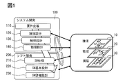
- FIG. 1 is an explanatory diagram showing a development procedure for system development.
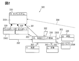
- FIG. 2 is an explanatory diagram showing a metamodel.
- FIG. 3 is an explanatory diagram showing a metamodel of requirement definition for system development.
- FIG. 4 is an explanatory diagram showing the design result of the requirement definition of the system development.
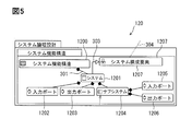
- FIG. 5 is an explanatory diagram showing a metamodel of the logical design of system development.
- FIG. 6 is an explanatory diagram showing the design result of the logical design of the system development.
- FIG. 7 is an explanatory diagram showing a metamodel of control design for system development.
- FIG. 1 is an explanatory diagram showing a development procedure for system development.
- FIG. 2 is an explanatory diagram showing a metamodel.
- FIG. 3 is an explanatory diagram showing a metamodel of requirement definition for system development.
- FIG. 4 is an explanatory diagram showing the design result of the requirement definition of the system development.
- FIG. 5 is an explanatory diagram showing a meta
- FIG. 8 is an explanatory diagram showing the design result of the control design of the system development.
- FIG. 9 is an explanatory diagram showing a metamodel of the physical design of system development.
- FIG. 10 is an explanatory diagram showing the design result of the physical design of the system development.
- FIG. 11 is an explanatory diagram showing a metamodel of the specification definition of software development.
- FIG. 12 is an explanatory diagram showing the design result of the specification definition of software development.
- FIG. 13 is an explanatory diagram showing a metamodel of the basic design of software development.
- FIG. 14 is an explanatory diagram showing the design result of the basic design of software development.
- FIG. 15 is an explanatory diagram showing a metamodel of detailed design of software development.
- FIG. 16 is an explanatory diagram showing the design result of the detailed design of software development.
- FIG. 17 is an explanatory diagram showing the design result of the detailed design of software development.
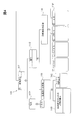
- FIG. 18 is an explanatory diagram showing the relationship between the database and the view.
- FIG. 19 is an explanatory diagram showing the relationship between the database and the view.
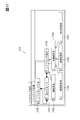
- FIG. 20 is an explanatory view showing an example of a view.
- FIG. 21 is an explanatory diagram showing the data structure of the database.
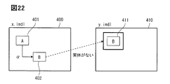
- FIG. 22 is an explanatory diagram showing inconsistencies between the design results.
- FIG. 23 is an explanatory diagram showing inconsistencies between the design results.
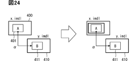
- FIG. 24 is an explanatory diagram showing inconsistencies between the design results.
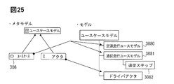
- FIG. 25 is an explanatory diagram showing the inconsistency between the metamodel and the design result.
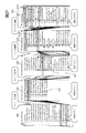
- FIG. 26 is an explanatory diagram showing a derivation relationship.
- FIG. 27 is an explanatory diagram showing a derivation relationship.
- requirement definition 110 is first performed.
- Requirement definition 110 is the setting of development goals, for example, to define cruise control.
- the logical design 120 is entered.
- the logical design 120 is to define a function definition and an input and an output.
- inputs include a driver's request, a driving condition of a car, and a road condition including the presence or absence of traffic congestion.
- output there are control items for what kind of control is performed, such as the degree of accelerator, the degree of braking, and the steering wheel operation.
- the control design 130 is a circuit design, and determines what kind of calculation formula is used for each control. For example, how to detect vehicle speed and obstacles.
- the physical design 140 is literally a design of which ECU the control is physically assigned to. For example, there is a division of roles between calculating the vehicle speed detection by the sensor ECU and calculating it by the engine control ECU.
- the software development 200 is a development in which the outline defined in the above system development 100 is concretely incorporated into the software, and the software specification definition 210 is first defined.
- the software specification definition 210 defines more specific details of the engine control ECU.
- each function defined in the system development 100 is divided into a plurality of layers, and what kind of input is obtained and how is output for each function is determined. Then, if there is a problem between the input and the output, how to check is determined.
- the detailed software design 230 is performed.
- the detailed design summarizes specific calculation methods in a flowchart or the like so that they can be described in a program language.
- the source code of the program is determined by this detailed design 230.
- the design system of this embodiment can be applied to both top-down development and bottom-up development due to the flexibility described later. However, whether it is top-down development or bottom-up development, detailed design of software that defines detailed controls from requirement definition 110 that determines what kind of system to create and creates specific flowcharts, etc. By 230 there are numerous definitions, which must always be inherited consistently.
- the design support tool of this embodiment can handle all a series of development designs from the requirement definition 110 of the system development 100 to the detailed design 230 of the software development 200.
- the design support tool of this embodiment does not necessarily have to be used in all processes. Depending on the content of development, for example, it may be used only for system development 100, or it may be used only for the process of requirement definition 110 of system development 100, or it may be used for the process of requirement definition 110 of system development 100 and specification definition of software development 200. It is also possible to use it in the process of only 210.
- the configuration adopted by the design support tool of this embodiment describes the development from the requirement definition 110 of the system development 100 to the detailed design 230 of the software development 200 described above, first, the items to be designed are represented as the metamodel 300, and the metamodel. Design based on 300.
- each design process 110, 120, 130, 140, 210, 220, and 230 includes the formulation of a metamodel 300 that determines the direction of development, and the design result 305 that is made based on the metamodel 300.
- the metamodel 300 defines the relationship between the two by connecting the relationships between the metaclasses 330, which are the elements constituting the metamodel, with a line.
- the line showing a black square at the tip connecting the first metaclass 3301 and the second metaclass 3302 represents the possession 301 defined in the vertical relationship, and the lower second metaclass 3302 is the upper first. Indicates that it is an element of metaclass 3301.
- the arrow connecting the second metaclass 3302 and the third metaclass 3303 represents the reference 302, and the content specified by the second metaclass 3302, for example, the field operates with reference to the field specified by the third metaclass. Indicates that it is something to do.
- Reference 302 indicates that there is some relevance to the data exchanged between the two metaclasses.
- the input port of the second metaclass 3302 is in a relationship of referring to the data of the control logic element of the third metaclass 3303.
- the relationship between the second metaclass 3302 and the third metaclass 3303 does not have to be in a hierarchical relationship, nor does it need to be in the same process. It is also possible for the input port of the second metaclass 3302 to refer to the contents of the control logic element designed in another process.
- the line showing a white triangle at the tip connecting the third metaclass 3303 and the fourth metaclass 3304 represents the inheritance 303, and the fourth metaclass 3304 is at the same level as the third metaclass 3303, in other words.
- the fourth metaclass 3304 indicates that it is one type of the third metaclass 3303.
- the third metaclass 3303 is a control logic element and the fourth metaclass 3304 is a waveform
- a waveform can be mentioned as one type of control logic element.
- the broken line represents the derivation 304
- the derivation 304 shows the relationship with other processes.
- the metaclass 330 of one process and the metaclass 330 of another process are connected by the derivation 304 relationship, it is based on the content of the metaclass 330 of one process. It shows that the metaclass 330 of the other process is defined.
- This derivation 304 is used as trace information, and details will be described later. However, by specifying the relationship of the derivation 304 between the request source and the request destination, it is possible to trace the design information across the processes.
- the design result 305 embodies the contents of the metaclass 330.
- the design result 305 uses three input ports, a first input port, a second input port, and a third input port, and is more specific than the name and size of the input port. Prescribe the content. Therefore, the design result 305 based on one metaclass may have a plurality of components. The relationship between each component includes ownership 301 and reference 302.
- FIG. 3 shows an example of the metamodel 300 of the requirement definition 110.
- the system requirement 111 is listed as the meta class 330, and further, the system requirement 111 defines the first system requirement 1110 and the second system requirement 1111 which has a relationship between the first system requirement 1110 and the possession 301. That is, the metamodel 300 stipulates that the system requirement 111 is multiplex.
- the second system requirement 1111 has a relationship of inheritance 303 between the metaclass 330 of the functional requirement 112 and the metaclass 330 of the non-functional requirement 113.
- the metaclass 330 of the non-functional requirement 113 has the relationship of the reliability requirement 114, the maintainability requirement 115, and the metaclass 330 of the efficiency requirement 116 as inheritance 303. Therefore, it is defined that the second system requirement 1111 has a functional requirement 112 and a non-functional requirement 113 of the reliability requirement 114, the maintainability requirement 115, and the efficiency requirement 116.
- the design of the requirement definition 110 is performed according to this metamodel 300.
- the constant speed running 117 is included, and in order to perform the constant speed running 117, the setting 1171 by the driver and the actual constant speed running are performed. Traveling 1172, which is the various requirements of the above, is required.
- For setting by the driver check the signal input from various devices such as the setting switch.
- the constant speed running 118 that calculates the acceleration / deceleration required to maintain the target speed and outputs the request to the engine control ECU, and the speed adjustment in various modes according to the driver's request are performed. It is necessary to adjust the target speed to be performed 119. Even when the constant speed running 118 is performed, the presence or absence of the preceding vehicle, the speed of the preceding vehicle, etc. are detected in the follow-up mode to calculate the maintenance speed of the vehicle speed 1181, or the engine control ECU controls the vehicle speed to make it more suitable. Make request 1182.
- Constant speed running 117, setting 1171, running 1172, implementation of constant speed running 118, target speed setting 119, items 1181, 1182, and study item 1191 all correspond to the multiplexed system requirement 111, and the system.
- Constant speed running 117, setting 1171, running 1172, implementation of constant speed running 118, target speed setting 119, items 1181, 1182, and study item 1191 all correspond to the multiplexed system requirement 111, and the system.
- each item of constant speed running 117, setting 1171, running 1172, execution of constant speed running 118, target speed setting 119, item 1181, 1182, and examination item 1191 becomes each component in the design result 305.
- the relationship between each component is the relationship of reference 302.
- FIG. 5 shows an example of the metamodel 300 of the logical design 120.
- the metaclass 330 of the system 1201 has a relationship of possession 301 with the system functional structure 1200, and the system functional structure 1200 defines that the system 1201 is included. Further, the system 1201 has a relationship of possession 301 with the metaclass 330 of the input port 1202, the output port 1203 and the subsystem 1204, and the system 1201 has the input port 1202, the output port 203 and the subsystem 1204. Similarly, subsystem 1204 also has input port 1205 and output port 1206.
- the system 1201 has a relationship between the metaclass 330 of the system component 1207 and the inheritance 303, and it is stipulated that the system 1201 includes the system component 1207. Further, the metaclass 330 of the system component 1207 defines the relationship of the derivation 304, and the relationship of the derivation 304 is defined in the system requirement 111 of the metamodel 300 of the requirement definition 110, more specifically, the metaclass 330 of the second system requirement 1111. It is tied. Therefore, it is defined that the system 1201 of the logical design 120 is derived from the system requirement 111 of the requirement definition 110 via the system component 1207.
- a deceleration determination 1211 for determining whether or not an operation for requesting deceleration has been performed by the driver, or an operation for requesting acceleration has been performed.
- the vehicle speed setting determination 1213 is performed.
- the inter-vehicle distance determination 1214 for determining whether or not the driver has performed an operation to shorten the inter-vehicle distance with the preceding vehicle and the inter-vehicle length determination 1215 for determining whether or not the operation for increasing the inter-vehicle distance has been performed are performed.
- the inter-vehicle distance setting determination 1216 for determining the inter-vehicle distance is performed.
- the vehicle speed calculation item 122 the vehicle speed is calculated by the acceleration calculation 1221 that calculates the acceleration / deceleration based on the signals from various sensors and the wheel calculation 1222 that determines the actual wheel speed. Then, the difference between the vehicle speed calculated by the vehicle speed calculation item 122 and the required vehicle speed determined by the vehicle speed setting determination 1213 of the driver's request determination item 121 is calculated by the vehicle speed difference calculation item 123. Similarly, in the inter-vehicle distance difference calculation item 124, the difference between the inter-vehicle distance setting determination 1216 defined in the request determination item 121 and the inter-vehicle distance defined in the inter-vehicle distance calculation item 125 is calculated by the inter-vehicle distance difference calculation 1241.
- the information is input to the driver notification output item 127 and the target acceleration / deceleration amount calculation item 128.
- the driver notification output item 127 determines how quickly and appropriately the information such as the vehicle speed is displayed to the driver by the display output 1271, and determines the information to be output to various devices such as a meter.
- the system functional structure 1200 shows the overall structure, and the system 1201 included therein shows the driver's request determination item 121, the vehicle speed calculation item 122, the vehicle speed difference calculation item 123, and the inter-vehicle distance difference calculation.
- Item 124, inter-vehicle distance calculation item 125, system state determination item 126, driver notification output item 127, and target acceleration / deceleration amount calculation item 128 correspond to each other.
- Each system 1201 is provided with an input port 1202 and an output port 1203.
- each subsystem 1204 includes an input port 1205 and an output port 1206.
- the subsystem 1204 corresponds to the metaclass 330, and the deceleration judgment 1211, the speed increase judgment 1212, the vehicle speed setting judgment 1213, the vehicle distance short judgment 1214, and the vehicle distance length judgment 1215 and the inter-vehicle distance setting determination 1216 are each component of the design result 305.
- control design 130 designs the control in the system 1201 and the subsystem 1204 of the logical design 120, and the input port 1300 and the output port 1301 are the inputs of the input port 1202, the output port 1203, and the subsystem 1204 of the system 1201. Corresponds to port 1205 and output port 1206.
- control logic element 1302 has a relationship of reference 302 with the input port 1300 and the output port 1301, and the input port and the output port of the logical design 120 refer to the control logic element 1302.
- the waveform 1303, the pulse 1304, the constant 1305 and the calculation 1306 are in the relationship of inheritance 303, and the control logic is assembled using the waveform 1303, the pulse 1304, the constant 1305 and the calculation 1306. Is stipulated.
- the metaclass 330 of the operation 1306 has a relationship of the unary operation 1307 and the metaclass 330 of the polynomial operation 1308 and the inheritance 303, and the metaclass 330 of the unary operation 1307 and the polynomial operation 1308 also have a plurality of metaclasses 330 inherited 303. It is in. It is stipulated that the operation 1306 is performed using the items included in these metaclasses 330.
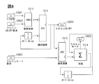
- FIG. 8 shows an example of the control design 130.
- This example corresponds to the system state determination item 126 of the logical design 120.
- the first and circuit 1311 calculates the signals of 12021 whether or not the ignition switch corresponding to the input port 1202 is turned on and the cruise control on / off state 12022. Then, the signal from the first and circuit 1311 and the delay signal of the unit are logically calculated by the X or circuit 1312, and the on / off of the cruise control is output.
- This output 12031 corresponds to the output port 1203 of the logical design 120.
- the output from the X or circuit 1312 and the cruise control mode signal 12023 are calculated by the second and circuit 1313.
- the mode signal 12023 corresponds to the input port 1202 of the logical design 120.
- the output of the second AND circuit 1313 and the delay signal of the unit are added and calculated by the addition circuit 1314, and the cruise control mode is output.
- the output 12032 corresponds to the output port 1203 of the logical design 120.
- the items defined in the logical design 120 are incorporated into a concrete logical operation formula.
- the input port corresponds to the metaclass 330.
- the components of the design result 305 include whether or not the ignition switch is turned on 12021 and the cruise control on / off state 12022.
- FIG. 9 shows an example of the metamodel 300 of the physical design 140. At the top is the metaclass 330 of the system physical structure 1400, and the metaclass 330 of the element 1401 has a relationship of possession 301.
- An example of the element 1401 is the ECU 1402, as the metaclass 330 of the ECU 1402 has an inheritance 303 relationship.
- the element 1401 (ECU 1402) has a functional component assignment 1403, an input port 1404, and an output port so that the metaclass 330 of the element 1401 has a functional component assignment 1403, and the metaclass 330 of the input port 1404 and the output port 1405 has a possession 301. It is equipped with 1405.
- Derivation 304 is shown in the functional component allocation 1403, and the functional component allocation 1403 of the physical design 140 is in a relationship of the subsystem 1204 of the logical design 120 and the derivation 304. Therefore, subsystem 1204 will achieve the functionality specified in functional component assignment 1403. Further, the functional component allocation 1403 also includes a derivation 304 from the software specification definition 210, which will be described later.
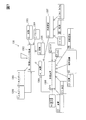
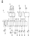
- FIG. 10 shows an example of the design result 305 of the physical design.
- examples of the ECU 1402 that divides the roles include a brake ECU 141, an ADASEC 142 that supports automatic operation, a meter ECU 143, an engine control ECU 144, and a power steering ECU 145.
- each ECU 141, 142, 142, 144, 145 correspond to the input port 1404.
- the wheel speed sensor 1461 that outputs a pulse signal indicating the wheel speed
- the millimeter wave radar 1462 that calculates the inter-vehicle distance from the preceding vehicle by the internal ECU and outputs the inter-vehicle distance signal that is the calculation result
- the touch panel 1464 This is the driver's request setting, etc., which is judged by the operation of various buttons. Examples of driver operations include cruise control mode, vehicle speed setting, cruise control on / off, and inter-vehicle distance setting.
- the on / off signal from the ignition switch 1464 determines whether the engine is running or stopped.
- the lane is detected by the image information from the camera 1465. Further, the acceleration / deceleration acceleration in the yaw rate and the traveling direction is detected by the signal from the acceleration sensor 1466.
- the steering angle of the steering wheel is detected by the signal from the steering sensor 1467.
- the ADASEC 142 that supports automatic operation includes the following.
- Targets for which the calculation results of each ECU 1402 are output include a display related to the set inter-vehicle distance from the meter ECU 143, a cruise control on / off display, a set vehicle speed display, and a cruise control mode display. These displays are output to the in-vehicle display 1471.
- the engine control ECU 144 outputs a rotation signal of the throttle motor 1472 to the throttle valve that controls the intake air amount, more specifically, to the throttle motor 1472 that rotates the throttle valve.
- the power steering ECU 145 outputs a rotation signal of the power steering motor 1473 to the power steering device. These outputs correspond to the output port 1405 of the metamodel 300.
- the relationship between the metamodel 300 and the design result 305 is as described above.
- the metaclass 330 is the ECU 1402
- the brake ECU 141 the ADASEC 142 that supports automatic operation
- the meter ECU 143 the engine control ECU 144
- the power steering ECU 145 Corresponds to the design result 305 components.
- FIG. 11 shows an example of the metamodel 300 of the software specification definition 210.
- the relationship of possession 301 is between each metaclass 330 of software requirement specification 2100, requirement group 2101, and software requirement 2102. Therefore, the software requirement specification 2100 includes the requirement group 2101, and the requirement group 2101 has a multiple structure including the software requirement 2102.
- the metaclass 330 of the software requirement 2102 has a relationship of inheritance 303 between the metaclass 330 of the functional requirement 2103 and the non-functional requirement 2104, and the metaclass 330 of the non-functional requirement 2014 further includes the reliability requirement 2105, the efficiency requirement 2106, and the non-functional requirement 2104.
- the metaclass 330 of the maintainability requirement 2107 is in the relationship of inheritance 303. Therefore, the software requirement 2102 defines a function requirement 2103, a reliability requirement 2105, an efficiency requirement 2106, and a non-functional requirement 2104 of the maintainability requirement 2107.
- the metaclass 330 of the software request 2102 has a relationship with the metaclass 330 of the functional component allocation 1403 of the physical design 140 in the system development 100 described above and the derivation 304. Therefore, the function specified in the functional component allocation 1403 corresponds to the function request 2103 and the non-functional request 2104 in the software request 2102.
- FIG. 12 shows an example of the design result 305 of the software specification definition 210 in the software development 200.
- the software specification definition 210 defines what kind of software each ECU 1402 is in charge of. For example, in item 211 for the ADASEC 142 that supports automatic operation, the maintainability request 2120 for maintainability common to the ECU, the usability request 2121 for the usability common to the ECU, the efficiency request 2122 for the efficiency of the ECU, and the ECU. There is a reliability requirement 2123 for the reliability of.
- a lower layer is defined for each request 2120 to 2123.
- a software maintainability requirement 2130 that reduces the number of changes in the software when the software is used in other vehicles.
- a status display request 2131 of a function that always displays what is effective among the functions that support the user (driver) in automatic driving.
- Program size request 2132 is, for example, a request to keep the actual used area within 70% of the capacity of various memories.
- the CPU load request 2133 is, for example, a request for suppressing the average load of the CPU within 60% in a state of steady automatic driving support.
- steady automatic driving support for example, while driving along the lane (lane keeping assist), while preparing to always operate the emergency brake, while maintaining the distance from the preceding vehicle, An example of following running at a constant speed can be mentioned.
- the part reliability requirement 2134 that continues to operate in other parts that are not affected by the defect is set.
- Each of these requirements 2120-2123 and 2130-2134 corresponds to the non-functional requirements 2104 of the metamodel 300. Therefore, in the relationship between the metamodel 300 and the design result 305, the non-functional requirements 2104 are metaclass 330, and each request 2120-2123 or 2130-2134 corresponds to the component of the design result 305.
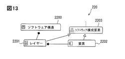
- FIG. 13 shows an example of the metamodel 300 of the software basic design 220.
- the software basic design 220 defines functions and data for realizing the requirements defined in the software specification definition 210. Since the software structure 2200, the layer 2201 and the metaclass 330 of the element 2202 are in the ownership relationship, the software structure 2200 includes the layer 2201, and the layer 2201 includes the element 2202.
- the metaclass 330 of the layer 2201 and the element 2202 has a relationship of the metaclass 330 of the software component 2203 and the inheritance 303, the layer 2201 and the element 2202 can be mentioned as the type of the software component 2203.
- the metaclass 330 of the software component 2203 has a relationship with the metaclass 330 of the software request 2102 of the software specification definition 210 and the derivation 304. Therefore, the layer 2201 of the software basic design 220 and the element 2202 included in the layer 2201 are related to the software requirement 2102 of the software specification definition 210.
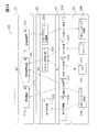
- FIG. 14 shows an example of the design result 305 of this software basic design 220.
- the application layer (APP layer) 221 has items of a vehicle speed deviation 2210, an inter-vehicle distance deviation 2211, and a target control amount 2212.
- the application framework layer (AFW layer) 222 which is the layer below it, contains items such as the presence / absence of a preceding vehicle 2222, the cruise control control state 2221, and the external system control amount 2222.
- the platform layer (PF layer) 223 has items of preceding vehicle information 2230, own vehicle driving information 2231, external system state 2232, switch state 2233, and external system request 2234.
- the lowest layer, the hardware layer (HW layer) 224 is a network controller (reception) 2240 and an ignition that can also be used for in-vehicle devices as devices that output signals that are the prerequisites for each of the above items.
- the APP layer 221 and the AFW layer 222, the PF layer 223, and the HW layer 224 correspond to the layer 2201 of the metamodel 300. Then, the items of the vehicle speed deviation 2210, the inter-vehicle distance deviation 2211, and the target control amount 2212, the presence / absence of the preceding vehicle 2220, the control state of the cruise control 2221, the item of the external system control amount 2222, the preceding vehicle information 2230, and the own vehicle traveling information 2231.
- External system state 2232, switch state 2233, and items of external system request 2234 network controller (receive) 2240 that can also be used for in-vehicle devices, ignition switch 2241, various switches 2242, and networks that can also be used for in-vehicle devices.
- 2243 of the controller (transmission) 2243 corresponds to the element 2202 included in each layer 2201.
- each layer from the APP layer 221 to the HW layer 224 is shown by a broken line arrow.
- the signal from the ignition switch 2241 of the HW layer 224 is taken into the item of the external system state 2232 of the PF layer 223, and is taken into the item of the cruise control control state 2221 of the AFW layer 222 together with the item of the switch state 2233. Then, this control state 2221 is output to the vehicle speed deviation 2210 and the inter-vehicle distance deviation 2211 of the APP layer 221.
- the arrow in FIG. 14 shows the relationship between each layer 2201 of the design result 305, and has nothing to do with the arrow of the metamodel 300.
- layer 2201 is a metaclass 330
- APP layer 221 and AFW layer 222, PF layer 223, and HW layer 224 are components of the design result 305.
- the detailed software design 230 defines the detailed control for realizing the functions of the basic design 220.
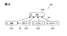
- An example of the metamodel 300 is shown in FIG.
- the metaclass 330 of element 2300 is the same as the metaclass 330 of element 2202 of basic design 220.
- the metaclass 330 of the element 2300 has a relationship of possession 301 with each metaclass 330 of the function 2301, the data 2302, the input port 2303, and the output port 2304. Therefore, element 2300 includes function 2301, data 2302, input port 2303 and output port 2304.
- the metaclass 330 of the data 2302 is also owned by the metaclass 330 of the function 2301, the data 2302 is used for the element 2300 and also for the function 2301.
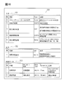
- the design result 305 of the software detailed design 230 defines the arithmetic processing by using, for example, a flowchart or a table as shown in FIG.
- the input items 231 are "1. Cruise control state”, “2. Vehicle speed”, “3. Presence / absence of preceding vehicle”, “4. Measured inter-vehicle distance", and “5. Set inter-vehicle distance”.
- the output item 232 includes "1. Difference between the measured inter-vehicle distance and the set inter-vehicle distance”.
- the internal data 233 includes "1. target vehicle speed” and "2. actually measured vehicle speed”.
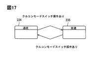
- the design result 305 of the software detailed design 230 shows that, for example, as shown in FIG. 17, the state when the cruise control switch is operated using the state transition control is the follow-up running 234 and the constant speed running 235. Indicates that it will switch with. Although the definitions of the follow-up running 234 and the constant speed running 235 are not described in the state transition of FIG. 17, the definitions are defined in detail in the actual detailed design.
- the input item 231 is a metaclass 330, and "1. Cruise control status", "2. Vehicle speed”, “3. Presence or absence of a preceding vehicle”, “4. Measured inter-vehicle distance”, “5. Set inter-vehicle distance”. "Distance” is a component of the design result 305.
- the design support tool of this embodiment defines all the series of development designs from the requirement definition 110 of the system development 100 to the detailed design 230 of the software development 200 in the metamodel 300, and defines the metamodel 300. Proceed with the design according to the contents. Then, the information of the metamodel 300 and the design result 305 during that period are recorded in one database 310 (FIG. 18).
- the database 310 does not have to be physically one, and may be distributed.
- the system state determination 3101 when the system state determination 3101 is written to the subsystem 3100 as a design result in the database 310, the system state determination 3101 can also be displayed as the system state determination 126 of the logical design 120 as shown in FIG. It can also be displayed as the system state determination 1425 of the design 140.
- the design support tool of this embodiment can display the design result 305 in a plurality of formats.
- the design tool of this embodiment can input design information from a plurality of screens.
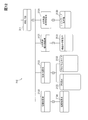
- FIG. 19 shows the design result 305 of the software basic design 220
- the left view 307 is an ER diagram which is an entity-relationship diagram, which is the same as that of FIG.
- the description content of this ER diagram can also be displayed in the tabular view 307 on the right screen.
- the view 307 is displayed on the liquid crystal display 320 (FIG. 27).
- the tabular view 307 describes as the debt of the APP layer 221 "the target amount of acceleration / deceleration is displayed from the difference between the vehicle speed and the inter-vehicle distance", and the element 2202 is "1. inter-vehicle distance deviation 2211". , "2. Target control amount 2212", “3. Vehicle speed deviation 2210", and the responsibilities of each element 2202 are described. The same applies to the layer 2201 below the AFW layer 222.
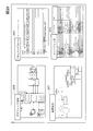
- the format of the view 307 used in the design tool of this embodiment is not limited to the ER diagram 3070 and the tabular document form 3072, but can also be represented as a tree diagram 3071 or a tree grid 3073 as shown in FIG. The designer can appropriately select an easy-to-use view 307 according to each design need.
- An ER diagram 3070 is preferred for an overview of the overall structure, and document form 3072 is preferred for defining the details of each item.
- the four types of views 307 of FIG. 20 are examples that are easy to use for designing, the views 307 used in the design support tool of this embodiment are not limited to these four types. .. On the contrary, it is possible to reduce the number of types of views 307 to less than four.
- the design support tool of this embodiment simply changes the appearance of each component based on the data stored in the database 310 for the display of each view 307. Therefore, any view is used.
- the input from 307 is the same as the input to the database 310.
- FIG. 21 shows an example of how to hold data in the database 310.
- the connection 148 is specified by the ID 1480 of the connection 148 itself, the ID 1488 of the association source, and the ID 1482 of the association destination in the database 310. Do. Then, various data related to the connection 148 are stored. For example, there are names, data itself, data versions, deletion information, and the like.
- connection 148 in FIG. 21 is the relationship of the reference 302.
- the relationship between the metaclass 330 includes the possession 301, the reference 302, the inheritance 303, and the derivation 304, the relationship is stored in the database 310. ..
- the information stored in the database 310 there is also a relationship between the metaclass 330 and the components of the design result 305 based on the metaclass 330.
- the ID information of each component and the ID information of the metaclass 330 related to the component are stored.
- the metaclass 330 may correspond to a plurality of other components of the design result 305. At that time, not only the information between the metaclass 330 and the components but also the information between the components is stored in the database 310. Relationships between components include ownership and reference.
- the metamodel 300 can be defined by using the various views 307 shown in FIG. 20, and the metamodel 300 can be designed in correspondence with the metamodel 300. Then, only by designing with any one view 307, the design result 305 can be displayed in all the views 307 formats of FIG. 20.
- the related design result 305 is always the latest, and there is no concern about update omission in the design support tool of this embodiment.
- the design support tool of this embodiment can freely change the metamodel 300 and the design result 305 in each design process without being bound by a specific rule. Therefore, it is possible to carry out detailed design by examining each component side only by defining a rough design by top-down development. It is a design support tool suitable for large-scale system development.
- the design support tool of this embodiment is bottom-up because the metamodel 300 and the design result 305 can be rewritten in each design process even when performing a high-level design using the components designed in detail in the low-level design. Also suitable for design.
- component A401 and component B402 are used in X design result 400, and when the component B402 refers to component B411 of Y design result 410, the component in Y design result 410.
- component B411 is deleted, an inconsistency occurs between the X design result 400 and the Y design result 410.
- component A401 and the component B402 are used in the X design result 400 and the component B402 refers to the component B411 of the Y design result 410, the same component B has the Z design. If it is also defined as component B421 of result 420, an inconsistency will occur between component B411 of Y design result 410 and component B421 of Z design result 420.
- the component A401 of the X design result 400 may be deleted while the component B411 of the Y design result 410 refers to the component A401 of the X design result 400. Inconsistency occurs in which the design result 305 of the citation destination is deleted and the actual situation disappears.
- the use case 308 corresponds to the constant speed running 3080 and the following running 3081, but when the following step 3082 is further added to the following running 3081, between the metamodel 300 and the design result 305. Inconsistency occurs.
- the design support tool of this embodiment can make corrections at each point of design as described above, it is allowed that such inconsistency occurs. By allowing this inconsistency, it is possible to provide flexibility as a design support tool and continue the design without stressing the designer.
- the design support tool of this embodiment detects the inconsistency and notifies the designer of the inconsistency, and the designer designs in a consistent metamodel 300 and based on the metamodel 300.
- the result 305 can be easily corrected. Inconsistency is detected when the file is opened or when the metamodel 300 is changed by deleting, editing, or merging.
- the display "A deleted model was found.” Is displayed on the display 320 (FIG. 27), and the file name of the X design result 400 and the component that is the related source are displayed.
- the class name of A401, the related class name of related a403, and the index number of the collection indicating the metamodel of component B402 are displayed.
- the metaclass 330, the corresponding component A401, and the component B402 are stored in the database 310, and the component A401 and the component B402 are also stored in a reference relationship. is there. Therefore, it can be detected that the deletion of the component B402 causes an inconsistency in the reference relationship.
- the display "A duplicate model was found in a plurality of files" is displayed on the display 320, the file names of the Y design result 410 and the Z design result 420, and the component B411. , 421 model paths are displayed.
- the database 310 stores that the component B402 of the X design result 400 and the component B411 of the Y design result 410 are in a reference relationship together with their respective ID information.
- the fact that the component B 402 of the X design result 400 and the component B421 of the Z design result 420 are in a reference relationship is also stored together with the respective ID information. Therefore, the database 310 can detect inconsistencies in the reference relationships.
- the designer does not need to use a special inconsistency correction function. For example, it is possible to adopt the component B411 found first and skip the component B421 found later.
- the component B411 found first may be deleted and the component B421 found later may be adopted by using the normal editor function. Conversely, it is also possible to delete the component B421 found later.
- the design support tool of this embodiment shows on the display 320 that "a model without a parent has been found" when an inconsistency is detected, and the file name of the X design result 400 And the related class name of the related a403 is displayed.
- the design support tool of this embodiment has the same operation as when the Y design result 410 is read by itself, and does not provide a special inconsistency correction function.
- the designer responds by moving the X design result 400 to an appropriate position or canceling the deletion of the X design result 400 by using a normal design function.
- an error message is displayed even when the operation that caused the inconsistency is performed.
- the design support tool displays an error message even when the X design result 400 is deleted.
- the relationship between the components of the design result 305 was a reference relationship, but similar inconsistencies can also be detected in the ownership relationship.
- the database 310 stores references and ownership as information between the components of the design result 305.
- the display 320 shows the message "A model in which the metamodel does not exist" is displayed, and the model file name of the metamodel 300 Display the model name of follow-up step 3082 corresponding to non-existent use case 308.
- the database 310 stores the relationship between the metaclass 330 of use case 308 and the components of the design result 305.
- the follow-up step 3082 When the follow-up step 3082 is added as a component, the follow-up step 3082 has a relationship that is not in the metaclass 330, so that the inconsistency can be detected.
- the design support tool of this embodiment does not provide a special inconsistency correction function.
- the designer can correct the inconsistency by deleting the follow-up step 3082 using a normal editor function.
- the design support tool of this embodiment can display the above error message because the database 310 stores the relationship between the possession 301 and the reference 302 as information.
- the possession 301 and the reference 302 define the relationship between different metaclasses 330, and the components of the design result 305 in each process follow this relationship by being associated with the metaclass 330.
- the possession 301 and the reference 302 are also stored in the database 310 as information between the components of the design result 305. Therefore, if there is a contradiction between the component of the design result 305 and the metaclass 330, or in the interrelationship of the components, the database 310 can detect the contradiction.
- the design tool of this example automatically ensures traceability. Top-down development is easy to understand, but in the development from the requirement definition 110 of the system development 100 to the detailed design 230 of the software development 200, consistency is required between the upper process and the lower process. "Traceability” is to centrally manage the relationships between work products (components) between these processes so that when a design, manufacturing, or maintenance problem occurs, the cause of the problem can be quickly traced. Management ".
- the design information from the upper process to the lower process is defined by the inheritance 303 and the derivation 304 in the metamodel 300, so that the metamodel of the lower process is associated with the metamodel 300 defined in the upper process. 300 can be created.
- the metamodel 300 of the upper process can be created in association with the metamodel 300 defined in the lower process.
- FIG. 26 is a diagram illustrating the operation of the derivation 304 on the display 320.
- the display 320 can display the requirement definition 110 of the upper process and the software basic design 220 of the lower process side by side on the left and right sides of the screen. Then, when trying to design the inter-vehicle distance deviation component 2211 on the APP layer 221 of the software basic design 220 on the right screen, drag the constant speed running 117 on the left screen with the mouse and drop it at the location of the inter-vehicle distance deviation component 2211. .. By this intuitive operation, the inter-vehicle distance deviation component 2211 is derived from the constant speed running 117.
- the derivation 304 is recorded by the designer operating the metamodels 300 of the left and right screens on the screen and associating them with each other. That is, the database 310 automatically records the designer's derivation operation as trace information.
- the database 310 automatically records that the inter-vehicle distance deviation component 2211 and the constant speed running 117 have a derivation 304 relationship. More specifically, at what point in time the derivation 304 was performed is stored in the database 310. What is stored in the database 310 is the relationship of the derivation 304, the ID information of the derivation destination, and the ID information of the derivation source. Therefore, the relationship of the derivation 304 can be used as trace information.
- the designer can intuitively grasp the relationship of the derivation 304 by connecting the relationship with a line.
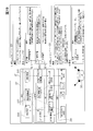
- the requirement definition 110, the logical design 120, and the physical design of the system development 100, and the software specification definition 210 and the basic design are displayed side by side on the display 320, and the relationship of the derivation 304 is connected by a line.
- the constant speed running 117 of the requirement definition 110, the driver notification output 127 of the logical design 120, the meter ECU 143 of the physical design 140, the following running 2109 of the software specification definition 210, and the vehicle speed deviation 2210 of the basic design 220 are derived.
- the design support tool of this embodiment the metamodel 300 in each process of design is defined, and the design in accordance with the regulation is defined. Then, the derivation 304 relationship between each component of the upper process and the lower process is stored in the database 310. Therefore, the design support tool of this embodiment can intuitively grasp whether all the requirements of the upper process are incorporated into the functions of the lower process. In other words, it is possible to grasp whether or not a function that is not required by the upper process is created in the lower process. Therefore, when making a design change, it is possible to grasp the range affected by the design change.
- the display 320 usually uses the liquid crystal screen of a computer, but it can also be printed out on a paper medium if necessary.
- the design support tool is usually operated by using a mouse or a keyboard, but input information can also be operated by image recognition or voice recognition. Further, the design support tool may be operated by taking in the information input by another device.
- the design mode of the system development 100 is defined as the requirement definition 110, the logical design 120, the control design 130, and the physical design 140, and the design mode of the software development 200 is defined as the specification definition 210, the basic design 220, and the detailed design 230. It is common to do this, but other prescribed methods may be used.
- the design support tool of this embodiment can view the design results in a plurality of views, and the characteristics of the design support tool of this embodiment are not changed by the name of each process.
- the relationship between the metaclass 330 of the metamodel 300 includes all the possession 301, the reference 302, the inheritance 303, and the derivation 304, but some relationships may be deleted depending on the usage pattern. Conversely, additional relationships may be added.
- This disclosure can be used as a design support tool, and can be used for designing, for example, when developing a large-scale system such as an automatic driving system for an automobile.
- the present disclosure can also be used as a design support method.
- the design support method used in the design support tool that supports the design of at least one process defines a metamodel by at least one metaclass, designs the process based on this metamodel, and stores the design contents in the database.
- the design content is displayed as a view on the display, and the view of the display is a plurality of displays having different description formats.
Landscapes
- Engineering & Computer Science (AREA)
- General Engineering & Computer Science (AREA)
- Theoretical Computer Science (AREA)
- Software Systems (AREA)
- Physics & Mathematics (AREA)
- General Physics & Mathematics (AREA)
- Geometry (AREA)
- Aviation & Aerospace Engineering (AREA)
- Automation & Control Theory (AREA)
- Computational Mathematics (AREA)
- Mathematical Analysis (AREA)
- Mathematical Optimization (AREA)
- Pure & Applied Mathematics (AREA)
- Computer Hardware Design (AREA)
- Evolutionary Computation (AREA)
- Stored Programmes (AREA)
Priority Applications (2)
| Application Number | Priority Date | Filing Date | Title |
|---|---|---|---|
| EP20868683.2A EP4036706A4 (de) | 2019-09-23 | 2020-09-01 | Designhilfswerkzeug |
| US17/700,288 US12056466B2 (en) | 2019-09-23 | 2022-03-21 | Assistance tool |
Applications Claiming Priority (2)
| Application Number | Priority Date | Filing Date | Title |
|---|---|---|---|
| JP2019-172388 | 2019-09-23 | ||
| JP2019172388A JP6847382B1 (ja) | 2019-09-23 | 2019-09-23 | 設計支援ツール |
Related Child Applications (1)
| Application Number | Title | Priority Date | Filing Date |
|---|---|---|---|
| US17/700,288 Continuation US12056466B2 (en) | 2019-09-23 | 2022-03-21 | Assistance tool |
Publications (1)
| Publication Number | Publication Date |
|---|---|
| WO2021059896A1 true WO2021059896A1 (ja) | 2021-04-01 |
Family
ID=74879235
Family Applications (1)
| Application Number | Title | Priority Date | Filing Date |
|---|---|---|---|
| PCT/JP2020/033088 Ceased WO2021059896A1 (ja) | 2019-09-23 | 2020-09-01 | 設計支援ツール |
Country Status (4)
| Country | Link |
|---|---|
| US (1) | US12056466B2 (de) |
| EP (1) | EP4036706A4 (de) |
| JP (1) | JP6847382B1 (de) |
| WO (1) | WO2021059896A1 (de) |
Citations (4)
| Publication number | Priority date | Publication date | Assignee | Title |
|---|---|---|---|---|
| JP2000353083A (ja) * | 1999-04-07 | 2000-12-19 | Nippon Steel Corp | 要求仕様記述支援装置およびその方法、記録媒体 |
| US20100162208A1 (en) | 2008-12-19 | 2010-06-24 | International Business Machines Corporation | Modeling tool builder - graphical editor construction |
| JP2010182184A (ja) * | 2009-02-06 | 2010-08-19 | Toshiba Corp | 仕様管理装置及び仕様管理プログラム |
| JP2010244229A (ja) * | 2009-04-03 | 2010-10-28 | Nec Corp | 情報管理装置 |
Family Cites Families (18)
| Publication number | Priority date | Publication date | Assignee | Title |
|---|---|---|---|---|
| US7000219B2 (en) * | 2000-11-03 | 2006-02-14 | Wilde Technologies Limited | Software development process |
| US8104017B2 (en) * | 2001-10-25 | 2012-01-24 | The Mathworks, Inc. | Traceability in a modeling environment |
| US10296305B2 (en) * | 2013-09-27 | 2019-05-21 | Rudolf Markus PETRI | Method and device for the automated production and provision of at least one software application |
| WO2016118979A2 (en) * | 2015-01-23 | 2016-07-28 | C3, Inc. | Systems, methods, and devices for an enterprise internet-of-things application development platform |
| US10831449B2 (en) * | 2015-04-28 | 2020-11-10 | Lexica S.A.S. | Process and system for automatic generation of functional architecture documents and software design and analysis specification documents from natural language |
| EP3296866B1 (de) * | 2015-05-13 | 2022-09-14 | Huebra, Nadia Analía | Computerimplementiertes verfahren zur darstellung von software-artigen anwendungen auf basis von designspezifikationen |
| US11055451B2 (en) * | 2015-10-28 | 2021-07-06 | Qomplx, Inc. | System and methods for multi-language abstract model creation for digital environment simulations |
| WO2017072969A1 (ja) * | 2015-10-30 | 2017-05-04 | 株式会社 東芝 | システム設計装置及び方法 |
| US9823906B2 (en) * | 2016-03-31 | 2017-11-21 | Sap Se | Complementary model-driven and textual development using enforced formatting constraints |
| CN109791575B (zh) * | 2016-05-24 | 2024-05-14 | 科特罗尔有限责任公司 | 一种应用于机电系统的自动化设计系统及方法 |
| US20180204149A1 (en) * | 2017-01-17 | 2018-07-19 | Xerox Corporation | Domain-specific business objects for process design |
| KR102038131B1 (ko) * | 2017-09-08 | 2019-10-31 | 주식회사 경신 | 차량용 제어기 소프트웨어 설계 자동화 장치 및 방법 |
| DE112018005879T5 (de) * | 2017-11-16 | 2020-08-20 | Intel Corporation | Verteilte softwaredefinierte industrielle Systeme |
| WO2019113508A1 (en) * | 2017-12-07 | 2019-06-13 | Fractal Industries, Inc. | A system and methods for multi-language abstract model creation for digital environment simulations |
| CN108196827B (zh) * | 2017-12-08 | 2021-04-02 | 南京航空航天大学 | 非形式化需求规约模板到形式化设计模型的自动转换方法 |
| CN109522002B (zh) * | 2018-10-29 | 2021-09-24 | 中国航空无线电电子研究所 | 一种基于模型驱动的无人机地面站开放式架构 |
| US10884717B2 (en) * | 2019-04-09 | 2021-01-05 | Raytheon Company | Resource management system featuring a sensor-agnostic software architecture |
| DE102020118563A1 (de) * | 2019-07-17 | 2021-01-21 | Steering Solutions Ip Holding Corporation | Middleware-system und -verfahren |
-
2019
- 2019-09-23 JP JP2019172388A patent/JP6847382B1/ja active Active
-
2020
- 2020-09-01 WO PCT/JP2020/033088 patent/WO2021059896A1/ja not_active Ceased
- 2020-09-01 EP EP20868683.2A patent/EP4036706A4/de active Pending
-
2022
- 2022-03-21 US US17/700,288 patent/US12056466B2/en active Active
Patent Citations (4)
| Publication number | Priority date | Publication date | Assignee | Title |
|---|---|---|---|---|
| JP2000353083A (ja) * | 1999-04-07 | 2000-12-19 | Nippon Steel Corp | 要求仕様記述支援装置およびその方法、記録媒体 |
| US20100162208A1 (en) | 2008-12-19 | 2010-06-24 | International Business Machines Corporation | Modeling tool builder - graphical editor construction |
| JP2010182184A (ja) * | 2009-02-06 | 2010-08-19 | Toshiba Corp | 仕様管理装置及び仕様管理プログラム |
| JP2010244229A (ja) * | 2009-04-03 | 2010-10-28 | Nec Corp | 情報管理装置 |
Non-Patent Citations (1)
| Title |
|---|
| See also references of EP4036706A4 |
Also Published As
| Publication number | Publication date |
|---|---|
| US20220206760A1 (en) | 2022-06-30 |
| JP2021051406A (ja) | 2021-04-01 |
| EP4036706A4 (de) | 2023-10-04 |
| EP4036706A1 (de) | 2022-08-03 |
| US12056466B2 (en) | 2024-08-06 |
| JP6847382B1 (ja) | 2021-03-24 |
Similar Documents
| Publication | Publication Date | Title |
|---|---|---|
| US12175210B2 (en) | Assistance tool | |
| US9352650B2 (en) | Rule-based cruise control system and method | |
| US11142212B2 (en) | Safety-aware comparator for redundant subsystems in autonomous vehicles | |
| CN110288847B (zh) | 一种自动驾驶决策方法、装置、系统、存储介质及终端 | |
| CN102862573B (zh) | 车辆节油方法和系统 | |
| Raghupatruni et al. | Empirical testing of automotive cyber-physical systems with credible software-in-the-loop environments | |
| JP6847381B1 (ja) | 設計支援ツール | |
| JP6847382B1 (ja) | 設計支援ツール | |
| US20230339491A1 (en) | Minimal-prerequisite interaction protocol for driver-assisted automated driving | |
| CN108644374A (zh) | 变速箱控制方法及装置 | |
| CN115826452A (zh) | 基于SysML的智能驾驶系统建模方法、装置、设备及介质 | |
| GB2555694A (en) | Collision-warning system | |
| CN112230659B (zh) | 精准规划运动轨迹的方法、智能控制设备及自动驾驶车辆 | |
| US20250156166A1 (en) | Method, Device and Computer Program Product for Producing a User-Specific Functionality of a Vehicle | |
| US12172669B2 (en) | Automated driving system with desired level of driving aggressiveness | |
| Grottoli et al. | A high fidelity driving simulation platform for the development and validation of advanced driver assistance systems | |
| US20250319863A1 (en) | Vehicle control governor | |
| KR20250076023A (ko) | 교통류 시뮬레이션을 위한 자율주행 차량 로직 생성 장치 및 방법 | |
| JP2025139965A (ja) | 設計支援システム、設計支援プログラム、設計支援プログラムを記録した記録媒体 | |
| Yamada et al. | Implementation and evaluation of data management methods for vehicle control systems | |
| Xie et al. | Autonomous Driving System of Intelligent Connected Vehicle Based | |
| Eom et al. | A Study on Mode Awareness of Multi-level Automated Vehicles | |
| Morelli¹ et al. | PhiSystem: a tooled methodology for design and validation of ADAS | |
| CN116620320A (zh) | 危害事件生成方法、装置、计算机设备和存储介质 | |
| CN121209308A (zh) | 一种矿用自卸车无人驾驶仿真系统、方法及电子设备 |
Legal Events
| Date | Code | Title | Description |
|---|---|---|---|
| 121 | Ep: the epo has been informed by wipo that ep was designated in this application |
Ref document number: 20868683 Country of ref document: EP Kind code of ref document: A1 |
|
| NENP | Non-entry into the national phase |
Ref country code: DE |
|
| ENP | Entry into the national phase |
Ref document number: 2020868683 Country of ref document: EP Effective date: 20220425 |