WO2021060302A1 - 作業機械 - Google Patents
作業機械 Download PDFInfo
- Publication number
- WO2021060302A1 WO2021060302A1 PCT/JP2020/035871 JP2020035871W WO2021060302A1 WO 2021060302 A1 WO2021060302 A1 WO 2021060302A1 JP 2020035871 W JP2020035871 W JP 2020035871W WO 2021060302 A1 WO2021060302 A1 WO 2021060302A1
- Authority
- WO
- WIPO (PCT)
- Prior art keywords
- bucket
- arm
- work
- target
- target surface
- Prior art date
- Legal status (The legal status is an assumption and is not a legal conclusion. Google has not performed a legal analysis and makes no representation as to the accuracy of the status listed.)
- Ceased
Links
Images








Classifications
-
- E—FIXED CONSTRUCTIONS
- E02—HYDRAULIC ENGINEERING; FOUNDATIONS; SOIL SHIFTING
- E02F—DREDGING; SOIL-SHIFTING
- E02F3/00—Dredgers; Soil-shifting machines
- E02F3/04—Dredgers; Soil-shifting machines mechanically-driven
- E02F3/28—Dredgers; Soil-shifting machines mechanically-driven with digging tools mounted on a dipper- or bucket-arm, i.e. there is either one arm or a pair of arms, e.g. dippers, buckets
- E02F3/36—Component parts
- E02F3/42—Drives for dippers, buckets, dipper-arms or bucket-arms
- E02F3/43—Control of dipper or bucket position; Control of sequence of drive operations
- E02F3/435—Control of dipper or bucket position; Control of sequence of drive operations for dipper-arms, backhoes or the like
- E02F3/439—Automatic repositioning of the implement, e.g. automatic dumping, auto-return
-
- E—FIXED CONSTRUCTIONS
- E02—HYDRAULIC ENGINEERING; FOUNDATIONS; SOIL SHIFTING
- E02F—DREDGING; SOIL-SHIFTING
- E02F3/00—Dredgers; Soil-shifting machines
- E02F3/04—Dredgers; Soil-shifting machines mechanically-driven
- E02F3/28—Dredgers; Soil-shifting machines mechanically-driven with digging tools mounted on a dipper- or bucket-arm, i.e. there is either one arm or a pair of arms, e.g. dippers, buckets
- E02F3/36—Component parts
- E02F3/42—Drives for dippers, buckets, dipper-arms or bucket-arms
- E02F3/43—Control of dipper or bucket position; Control of sequence of drive operations
- E02F3/435—Control of dipper or bucket position; Control of sequence of drive operations for dipper-arms, backhoes or the like
- E02F3/437—Control of dipper or bucket position; Control of sequence of drive operations for dipper-arms, backhoes or the like providing automatic sequences of movements, e.g. linear excavation, keeping dipper angle constant
-
- E—FIXED CONSTRUCTIONS
- E02—HYDRAULIC ENGINEERING; FOUNDATIONS; SOIL SHIFTING
- E02F—DREDGING; SOIL-SHIFTING
- E02F3/00—Dredgers; Soil-shifting machines
- E02F3/04—Dredgers; Soil-shifting machines mechanically-driven
- E02F3/28—Dredgers; Soil-shifting machines mechanically-driven with digging tools mounted on a dipper- or bucket-arm, i.e. there is either one arm or a pair of arms, e.g. dippers, buckets
- E02F3/36—Component parts
- E02F3/42—Drives for dippers, buckets, dipper-arms or bucket-arms
- E02F3/43—Control of dipper or bucket position; Control of sequence of drive operations
-
- E—FIXED CONSTRUCTIONS
- E02—HYDRAULIC ENGINEERING; FOUNDATIONS; SOIL SHIFTING
- E02F—DREDGING; SOIL-SHIFTING
- E02F3/00—Dredgers; Soil-shifting machines
- E02F3/04—Dredgers; Soil-shifting machines mechanically-driven
- E02F3/28—Dredgers; Soil-shifting machines mechanically-driven with digging tools mounted on a dipper- or bucket-arm, i.e. there is either one arm or a pair of arms, e.g. dippers, buckets
- E02F3/36—Component parts
- E02F3/42—Drives for dippers, buckets, dipper-arms or bucket-arms
- E02F3/43—Control of dipper or bucket position; Control of sequence of drive operations
- E02F3/435—Control of dipper or bucket position; Control of sequence of drive operations for dipper-arms, backhoes or the like
-
- E—FIXED CONSTRUCTIONS
- E02—HYDRAULIC ENGINEERING; FOUNDATIONS; SOIL SHIFTING
- E02F—DREDGING; SOIL-SHIFTING
- E02F3/00—Dredgers; Soil-shifting machines
- E02F3/04—Dredgers; Soil-shifting machines mechanically-driven
- E02F3/28—Dredgers; Soil-shifting machines mechanically-driven with digging tools mounted on a dipper- or bucket-arm, i.e. there is either one arm or a pair of arms, e.g. dippers, buckets
- E02F3/36—Component parts
- E02F3/42—Drives for dippers, buckets, dipper-arms or bucket-arms
- E02F3/43—Control of dipper or bucket position; Control of sequence of drive operations
- E02F3/435—Control of dipper or bucket position; Control of sequence of drive operations for dipper-arms, backhoes or the like
- E02F3/436—Control of dipper or bucket position; Control of sequence of drive operations for dipper-arms, backhoes or the like for keeping the dipper in the horizontal position, e.g. self-levelling
-
- E—FIXED CONSTRUCTIONS
- E02—HYDRAULIC ENGINEERING; FOUNDATIONS; SOIL SHIFTING
- E02F—DREDGING; SOIL-SHIFTING
- E02F9/00—Component parts of dredgers or soil-shifting machines, not restricted to one of the kinds covered by groups E02F3/00 - E02F7/00
- E02F9/20—Drives; Control devices
- E02F9/2025—Particular purposes of control systems not otherwise provided for
- E02F9/2041—Automatic repositioning of implements, i.e. memorising determined positions of the implement
-
- E—FIXED CONSTRUCTIONS
- E02—HYDRAULIC ENGINEERING; FOUNDATIONS; SOIL SHIFTING
- E02F—DREDGING; SOIL-SHIFTING
- E02F9/00—Component parts of dredgers or soil-shifting machines, not restricted to one of the kinds covered by groups E02F3/00 - E02F7/00
- E02F9/20—Drives; Control devices
- E02F9/22—Hydraulic or pneumatic drives
-
- E—FIXED CONSTRUCTIONS
- E02—HYDRAULIC ENGINEERING; FOUNDATIONS; SOIL SHIFTING
- E02F—DREDGING; SOIL-SHIFTING
- E02F9/00—Component parts of dredgers or soil-shifting machines, not restricted to one of the kinds covered by groups E02F3/00 - E02F7/00
- E02F9/20—Drives; Control devices
- E02F9/22—Hydraulic or pneumatic drives
- E02F9/2221—Control of flow rate; Load sensing arrangements
- E02F9/2225—Control of flow rate; Load sensing arrangements using pressure-compensating valves
- E02F9/2228—Control of flow rate; Load sensing arrangements using pressure-compensating valves including an electronic controller
-
- E—FIXED CONSTRUCTIONS
- E02—HYDRAULIC ENGINEERING; FOUNDATIONS; SOIL SHIFTING
- E02F—DREDGING; SOIL-SHIFTING
- E02F9/00—Component parts of dredgers or soil-shifting machines, not restricted to one of the kinds covered by groups E02F3/00 - E02F7/00
- E02F9/20—Drives; Control devices
- E02F9/22—Hydraulic or pneumatic drives
- E02F9/2264—Arrangements or adaptations of elements for hydraulic drives
- E02F9/2267—Valves or distributors
-
- E—FIXED CONSTRUCTIONS
- E02—HYDRAULIC ENGINEERING; FOUNDATIONS; SOIL SHIFTING
- E02F—DREDGING; SOIL-SHIFTING
- E02F9/00—Component parts of dredgers or soil-shifting machines, not restricted to one of the kinds covered by groups E02F3/00 - E02F7/00
- E02F9/20—Drives; Control devices
- E02F9/22—Hydraulic or pneumatic drives
- E02F9/2278—Hydraulic circuits
- E02F9/2282—Systems using center bypass type changeover valves
-
- E—FIXED CONSTRUCTIONS
- E02—HYDRAULIC ENGINEERING; FOUNDATIONS; SOIL SHIFTING
- E02F—DREDGING; SOIL-SHIFTING
- E02F9/00—Component parts of dredgers or soil-shifting machines, not restricted to one of the kinds covered by groups E02F3/00 - E02F7/00
- E02F9/20—Drives; Control devices
- E02F9/22—Hydraulic or pneumatic drives
- E02F9/2278—Hydraulic circuits
- E02F9/2285—Pilot-operated systems
-
- E—FIXED CONSTRUCTIONS
- E02—HYDRAULIC ENGINEERING; FOUNDATIONS; SOIL SHIFTING
- E02F—DREDGING; SOIL-SHIFTING
- E02F9/00—Component parts of dredgers or soil-shifting machines, not restricted to one of the kinds covered by groups E02F3/00 - E02F7/00
- E02F9/20—Drives; Control devices
- E02F9/22—Hydraulic or pneumatic drives
- E02F9/2278—Hydraulic circuits
- E02F9/2292—Systems with two or more pumps
-
- E—FIXED CONSTRUCTIONS
- E02—HYDRAULIC ENGINEERING; FOUNDATIONS; SOIL SHIFTING
- E02F—DREDGING; SOIL-SHIFTING
- E02F9/00—Component parts of dredgers or soil-shifting machines, not restricted to one of the kinds covered by groups E02F3/00 - E02F7/00
- E02F9/26—Indicating devices
- E02F9/264—Sensors and their calibration for indicating the position of the work tool
- E02F9/265—Sensors and their calibration for indicating the position of the work tool with follow-up actions (e.g. control signals sent to actuate the work tool)
Definitions
- the present invention relates to a work machine such as a hydraulic excavator.
- the bucket When performing construction using a hydraulic excavator (working machine) equipped with a front work device including a boom, arm and bucket, the bucket should move along the target surface (design surface) specified in the design drawing in advance.
- a control system that uses the prepared three-dimensional design data of the target surface to correct the operator's operation and operate the front work device to perform excavation and forming work semi-automatically.
- the excavation molding work includes (1) "excavation work” in which the cylinders of the boom and arm are automatically coordinated to move the tip of the bucket along the target surface and scrape the terrain, and (2) the bottom surface of the bucket.
- the bucket, boom, and arm cylinders are automatically coordinated to form the terrain so that the bottom of the bucket moves along the target surface while maintaining a state that is approximately parallel to the target surface.
- Patent Document 1 is given.
- the arm and boom are set so that the posture of the bucket with respect to the target surface is constant based on the shortest distance from the bucket to the target surface, the arm operation, and the bucket operation. Is automatically coordinated to move the bottom surface of the bucket along the target surface for leveling work.
- the bucket cylinder, the boom cylinder, and the arm cylinder are automatically coordinated to operate the bottom of the bucket. Automatically keeps the cylinder parallel to the target plane, while moving the bucket along the target plane to perform leveling work. As a result, the operator can easily perform the leveling work only by operating the arm.
- the bucket automatically holds the bucket posture for leveling work. No action is taken. That is, the bucket does not automatically operate when the operator wants to adjust the bucket posture by his / her own operation or when the bucket is separated from the target surface and returned.
- the posture of the bucket When performing leveling work, the posture of the bucket is generally such that the bottom surface of the bucket is almost parallel to the target surface as shown in FIG. 12 (a). On the other hand, little attention is paid to the posture of the bucket during the return work. Therefore, at the end of the return operation, for example, as shown in FIG. 12B, the line connecting the bucket rotation axis and the bucket toe may take a posture perpendicular to the target surface.
- the operator adjusts the bucket posture after the return work and sets the bottom surface of the bucket as the target surface as shown in FIGS. 13 (a) and 13 (b). On the other hand, move it closer to parallel and then move on to leveling work. At this time, by changing the bucket posture, d1thr is generated as the deviation of the shortest distance between the bucket and the target surface.
- the automatic bucket operation is activated even if an arm operation is input. do not do. Therefore, it is necessary to reduce the shortest distance between the bucket and the target surface to less than D1 by performing a boom lowering operation and bringing the toes closer to the target surface again before moving to the leveling work. That is, the useless boom lowering operation performed after the bottom surface of the bucket is parallel to the target surface impairs work efficiency.
- the threshold value D1 of the shortest distance between the bucket capable of automatic bucket operation and the target surface is set to be larger than d1thr. .. In that case, even if the bucket posture is adjusted as shown in FIG. 13B after the return operation, the distance d1thr between the bucket and the target surface is smaller than the threshold value D1, so if an arm operation is input, the operator moves to the leveling operation as it is. Can be done.
- the threshold value D1 of the shortest distance between the bucket and the target surface capable of automatic bucket operation is set large, the shortest distance between the bucket and the target surface may be less than the threshold value D1 during the return operation (for example, during the arm dump operation). Increase. If the shortest distance between the bucket and the target surface becomes less than the threshold value D1 during the arm dump operation, the bucket automatic operation may be activated contrary to the operator's intention, which may give the operator a sense of discomfort.
- the present invention has been made in view of the above problems, and an object of the present invention is to perform leveling work without impairing both work efficiency when shifting from return work to leveling work and operability during return work. Is to provide a working machine capable of performing.
- the present invention has a working device having a boom, an arm and a bucket, an operating device for operating the working device, and a toe of the bucket moving along a predetermined target surface.
- a working device having a boom, an arm and a bucket, an operating device for operating the working device, and a toe of the bucket moving along a predetermined target surface.
- the controller determines the target surface from the tip of the arm based on the attitude data and dimension data of the work device and the position data of the target surface.
- the arm tip deviation which is the distance to, is calculated, and when the calculated arm tip deviation is equal to or less than a predetermined threshold value, there is no bucket operation input to the operating device, and the arm operation input to the operating device is input.
- the leveling work control is executed and the calculated arm tip deviation is larger than the predetermined threshold value, or when there is an input of a bucket operation to the operating device, or an arm operation to the operating device.
- the excavation work control shall be executed.
- the leveling work can be performed without impairing both the work efficiency when shifting from the return work to the leveling work and the operability at the time of the return work. Issues, configurations and effects other than those described above will be clarified by the following description of the embodiments.
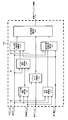
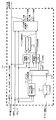
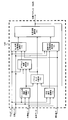
- FIG. 1st and 2nd Embodiment of this invention It is a perspective view which shows the work machine in 1st and 2nd Embodiment of this invention. It is a block diagram which shows the hydraulic drive device mounted on the work machine shown in FIG. It is a block diagram which shows the control device mounted on the work machine shown in FIG. It is a block diagram which shows the detailed structure of the information processing unit shown in FIG. It is a block diagram which shows the detailed structure of the excavation work target speed calculation part shown in FIG. It is a block diagram which shows the detailed structure of the offset deviation calculation part shown in FIG. It is a block diagram which shows the detailed structure of the leveling work target speed calculation part shown in FIG. It is a block diagram which shows the detailed structure of the target speed selection part shown in FIG.
- FIG. 1 is a perspective view showing a hydraulic excavator (working machine) according to the first embodiment of the present invention.
- the hydraulic excavator according to the present embodiment is an articulated work that is swingably attached to the lower traveling body 9 and the upper swinging body 10 which are the main bodies of the vehicle body and the upper swinging body 10 so as to be swingable.
- the device (front work device) 15 is provided.
- the lower traveling body 9 has crawler type traveling devices on the left and right, and is driven by the left and right traveling hydraulic motors 3b and 3a (only the left side 3b is shown).
- the upper swivel body 10 is mounted on the lower traveling body 9 so as to be swivel to the left and right, and is swiveled by the swivel hydraulic motor 4.
- the upper swing body 10 includes an engine 14 as a prime mover, a hydraulic pump device 2 driven by the engine 14 (first hydraulic pump 2a and second hydraulic pump 2b (see FIG. 2)), a control valve 20, and a flood control. It is equipped with a controller 500 (see FIGS. 2 and 3) that controls various types of excavators.
- the work device 15 has an articulated structure having a boom 11, an arm 12, and a bucket 8 which are a plurality of swingable front members.
- the boom 11 swings with respect to the upper swing body 10 due to the expansion and contraction of the boom cylinder 5
- the arm 12 swings with respect to the boom 11 due to the expansion and contraction of the arm cylinder 6, and the bucket 8 becomes the arm 12 due to the expansion and contraction of the bucket cylinder 7. It swings against it.
- the hydraulic excavator is provided near the connecting portion between the upper swing body 10 and the boom 11, and detects the angle (boom angle) of the boom 11 with respect to the horizontal plane.
- the first posture sensor 13a is provided near the connecting portion between the boom 11 and the arm 12, and the second posture sensor 13b for detecting the angle (arm angle) of the arm 12 with respect to the horizontal plane is connected to the arm 12 and the bucket 8.
- a third attitude sensor 13c provided on the bucket link 8a to detect the angle (bucket angle) of the bucket link 8a with respect to the horizontal plane, and a vehicle body posture to detect the inclination angle (roll angle, pitch angle) of the upper swivel body 10 with respect to the horizontal plane. It is equipped with a sensor 13d.
- a sensor 13d As the attitude sensor 13a-13d, for example, an IMU (Inertial Measurement Unit) can be used.
- the first attitude sensor 13a to the third attitude sensor 13c may be sensors that detect relative angles.
- attitude data including boom angle data, arm angle data, bucket angle data, and vehicle body angle data, respectively. ..
- the upper swivel body 10 is provided with a driver's cab.
- the right operating lever device 1a for traveling and the left operating lever device 1b for traveling are used.
- Right operating lever device 1c, left operating lever device 1d, etc. are arranged.
- the traveling right operation lever device 1a gives an operation instruction of the right traveling hydraulic motor 3a
- the traveling left operating lever device 1b gives an operation instruction of the left traveling hydraulic motor 3b
- the right operating lever device 1c gives an operation instruction to the boom cylinder 5 (boom 11).
- the left operation lever device 1d gives an operation instruction of the bucket cylinder 7 (bucket 8), and the left operation lever device 1d gives an operation instruction of the arm cylinder 6 (arm 12) and the swing hydraulic motor 4 (upper swing body 10).
- the operation device 1a-1d of the present embodiment is an electric lever, and generates an operation signal (electric signal) according to the operation amount input by the operator and outputs the operation signal (electric signal) to the controller 500.
- the operation device 1a-1d may be a hydraulic pilot type, and the operation amount may be detected by a pressure sensor and input to the controller 500.
- the control valve 20 is a pressure oil supplied from the hydraulic pump device 2 to each of the above-mentioned swivel hydraulic motor 4, boom cylinder 5, arm cylinder 6, bucket cylinder 7, and hydraulic actuators such as the left and right traveling hydraulic motors 3b and 3a. It is a valve device including a plurality of directional control valves (for example, directional control valves 21, 22, 23 in FIG. 2 which will be described later) for controlling the flow (flow rate and direction).
- the directional control valve in the control valve 20 is based on the signal pressure generated by the electromagnetic proportional valve (for example, the electromagnetic proportional valves 21a to 23b of FIG. 2 described later) based on the command current (control valve drive signal) output from the controller 500. It controls the flow (flow rate and direction) of the pressure oil that is driven and supplied to each of the hydraulic actuators 3-7.
- the drive signal output from the controller 500 is generated based on the operation signal (operation information) output from the operation lever device 1a-1d.
- FIG. 2 is a configuration diagram of a hydraulic drive device for the hydraulic excavator shown in FIG.
- the configuration will be described as a configuration in which only the boom cylinder 5, the arm cylinder 6, and the bucket cylinder 7 are provided as the hydraulic actuator, and the drain circuit and the like which are not directly related to the embodiment of the present invention will be illustrated and described. Is omitted. Further, the description of the load check valve having the same configuration and operation as the conventional hydraulic drive system will be omitted.
- the hydraulic pump device 2 includes a first hydraulic pump 2a and a second hydraulic pump 2b.
- the first hydraulic pump 2a and the second hydraulic pump 2b are driven by the engine 14 to supply pressure oil to the first pump line L1 and the second pump line L2, respectively.
- the first hydraulic pump 2a and the second hydraulic pump 2b will be described as a fixed-capacity hydraulic pump, but the present invention is not limited to this, and a variable-capacity hydraulic pump is used. You may.
- the control valve 20 is provided with two pump lines including a first pump line L1 and a second pump line L2.
- the first pump line L1 has a boom direction control valve 22 that controls the flow (flow rate and direction) of the pressure oil supplied to the boom cylinder 5, and a bucket direction that controls the flow of the pressure oil supplied to the bucket cylinder 7.
- the control valve 21 is connected.
- the pressure oil discharged by the first hydraulic pump 2a is supplied to the boom cylinder 5 and the bucket cylinder 7.
- an arm direction control valve 23 for controlling the flow of pressure oil supplied to the arm cylinder 6 is connected to the second pump line L2, and the pressure oil discharged by the second hydraulic pump 2b is the arm cylinder 6. Is supplied to.
- the boom direction control valve 22 and the bucket direction control valve 21 are configured to be capable of splitting by the parallel circuit L1a.
- Relief valves 26 and 27 are individually connected to the first pump line L1 and the second pump line L2, respectively. When the pressures of the respective pump lines L1 and L2 reach the preset relief pressures, the respective relief valves 26 and 27 are opened to release the pressure oil to the tank.
- the boom direction control valve 22 operates by the signal pressure generated by the electromagnetic proportional valves 22a and 22b.
- the arm direction control valve 23 operates by the signal pressures of the electromagnetic proportional valves 23a and 23b
- the bucket direction control valve 21 operates by the signal pressures of the electromagnetic proportional valves 21a and 21b.
- These electromagnetic proportional valves 21a to 23b reduce the pressure of the pilot pressure oil (primary pressure) supplied from the pilot hydraulic source 29 based on the command current (control valve drive signal) output from the main controller 500.
- the signal pressure generated in this manner is output to the control valves 21 to 23 in each direction.
- the right operation lever device 1c outputs a voltage signal according to the operation amount and operation direction of the operation lever to the main controller 500 as boom operation amount data and bucket operation amount data.
- the left operating lever 1d outputs a voltage signal corresponding to the operating amount and operating direction of the operating lever to the main controller 500 as arm operating amount data.
- the main controller 500 is set by inputting operation amount data to the front members 11, 12, and 8 input from the operation lever devices 1c and 1d and input from the leveling work control setting switch (leveling work control setting device) 17.
- a command signal (command current) for controlling each electromagnetic proportional valve 21a to 23b is calculated based on the dimensional data input from the vehicle body information storage device 19, and the calculated command signal is output to each electromagnetic proportional valve 21a to 23b. To do.
- Leveling work control setting switch 17 The leveling work control setting switch 17 is installed in the cab of the hydraulic excavator, and is changed to a switching position of either a permitted position or a prohibited position by an operator operation.
- the leveling work control setting switch 17 When the leveling work control setting switch 17 is switched to a permitted position that allows execution of leveling work control by the main controller 500, the leveling work control setting switch 17 outputs "true” as setting data. ..
- the leveling work control setting switch 17 outputs "false" as the setting data.
- the content of the setting data is determined by the switching position of the leveling work control setting switch 17, but the content of the setting data may be determined by another calculation in the controller 500.
- the angle of the bucket 8 with respect to the target surface may be calculated based on the above, and the setting data may be set to true if the value falls within a predetermined range, and false if the value does not fall within the predetermined range.
- the target surface setting device 18 is a device used for setting a target surface to be worked on and storing the position data (target surface data) of the set target surface, and outputs the target surface data to the main controller 500. ..
- the target surface data is data that defines the three-dimensional shape of the target surface, and in the present embodiment, the position information and the angle information of the target surface are included.
- the position of the target surface is defined as the relative distance information with the upper swivel body 10 (excavator) (that is, the position data of the target surface with respect to the hydraulic excavator 1)
- the angle of the target surface is defined as the relative angle information with respect to the gravity direction.
- the position may be the position coordinates on the earth
- the angle may be the relative angle to the vehicle body, and the data obtained by appropriate conversion may be used.
- the target surface setting device 18 may be provided with a preset target surface data storage function, and can be replaced with a storage device such as a semiconductor memory, for example. Therefore, it can be omitted when the target surface data is stored in, for example, a storage device in the controller 500 or a storage device mounted on the hydraulic excavator.
- the vehicle body information storage device 19 is the dimensional data of each part (for example, the lower traveling body 9, the upper turning body 10, and the front members 11, 12, 8 constituting the front working device 15) constituting the hydraulic excavator measured in advance. It is a device used for storage and outputs dimensional data to the main controller 500.
- the main controller 500 is a controller that controls various controls related to the hydraulic excavator.
- the main controller 500 has a target speed (for example, the hydraulic cylinder 5) for each of the front members 11, 12, and 8 so that the tip of the bucket 8 moves along the target surface.
- 6, 7 target speeds (target actuator speeds)) are calculated, and excavation work control that controls the work device 15 based on the target speed, and the posture of the bucket 8 with respect to the target surface (for example, the angle of the bottom surface of the bucket with respect to the target surface).
- FIG. 3 is a configuration diagram of the main controller 500 mounted on the hydraulic excavator shown in FIG.
- the main controller 500 includes, for example, a CPU (Central Processing Unit) (not shown), a storage device such as a ROM (Read Only Memory) or an HDD (Hard Disc Drive) for storing various programs for executing processing by the CPU, and a CPU. It is configured by using hardware including a RAM (Random Access Memory) which is a work area when executing a program.
- the information processing unit 100 that calculates the target actuator speed when the bucket 8 is moved along the target surface, and the control valve according to the calculated target actuator speed. It functions as a control valve drive unit 200 that generates the drive signals of 20.
- a control valve drive unit 200 that generates the drive signals of 20.
- the information processing unit 100 receives operation amount data from the operation lever devices 1c and 1d, attitude data from the attitude sensors 13a to 13d, setting data from the leveling work control setting switch 17, and target surface setting device 18. Based on the target surface data and the dimensional data from the vehicle body information storage device 19, the target actuator speeds of the hydraulic cylinders 5, 6 and 7 are calculated and output to the control valve drive unit 200.
- the control valve drive unit 200 generates a control valve drive signal according to the target actuator speed and drives the control valve 20.
- the details of the information processing unit 100 will be described with reference to FIG.
- the information processing unit 100 includes a toe deviation calculation unit 110, an excavation work target speed calculation unit 120, an arm tip deviation calculation unit 140, a bucket mode determination unit 150, an offset deviation calculation unit 160, and a leveling work target speed calculation. It functions as a unit 170 and a target speed selection unit 180.
- the information processing unit 100 outputs the target actuator speed calculated by the target speed selection unit 180 to the control valve drive unit 200.
- the tip deviation calculation unit 110 and the arm tip deviation calculation unit 140 are only outlined because the calculation contents are easy to understand, and the excavation work target speed calculation unit 120, the bucket mode determination unit 150, and the offset deviation calculation are provided.
- the details of the unit 160, the leveling work target speed calculation unit 170, and the target speed selection unit 180 will be described.
- the toe deviation calculation unit 110 calculates the distance between the toe of the bucket 8 and the target surface (toe deviation Dvt) from the position of the toe of the bucket 8 calculated from the attitude data and the dimensional data and the target surface data, and calculates the distance. The result is output as toe deviation data.
- the origin is the point where the lower traveling body 9 comes into contact with the ground on the turning center axis of the hydraulic excavator (upper turning body 10), and the X-axis in the front-rear direction of the car body.
- a coordinate system vehicle body coordinate system in which the Y-axis is set in the width direction of the vehicle body and the Z-axis is set in the vertical direction of the vehicle body is used.
- the toe deviation Dvt calculates the coordinates of the bucket toe in the vehicle body coordinate system based on the attitude data and dimensional data Lsb, Lbm, Lam, Lbk of each front member 11, 12, 8, and the coordinates and the vehicle body coordinate system. It can be calculated based on the position data of the target surface in.
- the arm tip deviation calculation unit 140 performs the same calculation as the toe deviation calculation unit 110 for the tip pin (bucket pin) of the arm 12. That is, from the position of the center of the tip pin of the arm 12 (sometimes referred to as “arm tip” or “bucket rotation center” in this paper) calculated from the attitude data and the dimensional data, and the target surface data, the arm tip The distance to the target surface (arm tip deviation) Dva (see FIG. 17) is calculated, and the calculation result is output as arm tip deviation data.
- the arm tip deviation Dva calculates, for example, the coordinates of the arm tip in the vehicle body coordinate system based on the posture data and dimensional data Lsb, Lbm, and Lam of the front members 11 and 12, and the coordinates and the target surface in the vehicle body coordinate system. It can be calculated based on the position data of.
- the excavation work target speed calculation unit 120 is the excavation work which is the target speed (target actuator speed) of the hydraulic cylinders 5, 6 and 7 at the time of excavation work control from the operation amount data, the attitude data and the dimensional data and the tip deviation data. Calculates the target speed and outputs it.
- the excavation work target speed calculation unit 120 can function as an excavation work target toe speed calculation unit 121, a toe speed calculation unit 122, a subtraction unit 123, an angular velocity inverse calculation unit 124, and a cylinder speed inverse calculation unit 125.
- the excavation work target toe velocity Vt is the target velocity of the component perpendicular to the target surface in the velocity vector generated in the bucket toe during the excavation work, and becomes smaller as the toe deviation approaches 0 (the closer the toe approaches the target surface). Is calculated as follows.
- the toe speed calculation unit 122 uses the arm operation amount data, the bucket operation amount data, the attitude data, and the dimension data among the operation amount data to determine the toe tip (bucket toe tip) when the bucket 8 and the arm 12 operate according to the operator operation. ),
- the arm bucket composite tip speed is calculated by geometric calculation as the speed in the direction perpendicular to the target plane.
- the subtraction unit 123 obtains the boom target toe speed by subtracting the arm bucket composite toe speed from the excavation work target toe speed Vt.
- the boom target toe speed is the toe speed due to the boom required to operate the toe at the excavation work target toe speed Vt when the bucket 8 and the arm 12 are operated according to the operator operation.
- the angular velocity inverse calculation unit 124 calculates the boom target angular velocity, which is the target angular velocity of the boom 11, by geometric calculation based on the boom target toe speed calculated by the subtraction unit 123, the attitude data, and the dimensional data. To do.
- the cylinder speed inverse calculation unit calculates the boom target angular velocity (target angular velocity of the boom 11) from the boom target angular velocity calculated by the angular velocity inverse calculation unit 124, the attitude data, and the dimensional data by geometric calculation.
- the excavation work boom target cylinder speed converted to the target speed of 5 is calculated.
- the arm operation amount data and the bucket operation amount data input to the excavation work target speed calculation unit 120 are the excavation work arm target cylinder speed which is the target speed of the arm cylinder 6 and the target speed of the bucket cylinder 7, respectively. It is converted to the excavation work bucket target cylinder speed, and is output to the target speed selection unit 180 as the excavation work target speed together with the excavation work boom target cylinder speed calculated by the cylinder speed inverse calculation unit 125.
- the excavation work target toe speed calculation unit 121 changes the excavation work target toe speed Vt according to the toe deviation data, but a plurality of proportional coefficients that differ depending on the magnitude of the toe deviation Dvt are used. It may be set or a different function may be used. Further, in the present embodiment, the bucket 8 and the arm 12 are operated according to the operation of the operator, and the boom 11 is used to make adjustments for operating the toes along the target surface. The toe deviation Dvt may be corrected, and the bucket 8 and / or the arm 12 and the boom 11 may be used to make adjustments for moving the toe along the target surface.
- the bucket mode determination unit 150 outputs the arm tip deviation data output by the arm tip deviation calculation unit 140, the setting data output by the leveling work control setting switch 17, and the operation lever devices 1c and 1d. Based on the operation amount data, it is judged whether or not the setting condition described later is satisfied, and the judgment result is output as a bucket mode flag.
- the setting condition referred to here is a condition for the main controller 500 to determine that the operator wants to execute the leveling work control, and the setting data is true (the setting switch 17 executes the leveling work control).
- the arm tip deviation Dva is equal to or less than the predetermined threshold dv1 (described later), and the size of the bucket operation amount determined from the operation amount data is from the predetermined threshold op1 (described later). It is small and the magnitude of the arm operation amount is larger than the predetermined threshold value op2 (described later).
- the bucket mode flag is output as "true”. If any of the above conditions related to the setting data, arm tip deviation Dva, bucket operation amount, and arm operation amount is not satisfied, it is determined that the bucket automatic operation is invalidated, and the bucket mode flag is set to "false”. Output.
- the distance (dimension Lbk) from the tip of the arm (center of rotation of the bucket) to the tip of the bucket can be considered as an example.
- the predetermined threshold value op1 related to the bucket operation amount a value close to zero that can determine the presence / absence of the bucket operation (presence / absence of the operation of the bucket cylinder 7) can be considered. If the bucket operation amount is smaller than the threshold value op1, it is determined that there is no bucket operation.
- the predetermined threshold value op2 related to the arm operation amount a value close to zero that can determine the presence / absence of arm operation (presence / absence of operation of the arm cylinder 6) can be considered. If the amount of arm operation is larger than the threshold value op2, it is determined that there is arm operation.
- Offset deviation calculation unit 160 calculates the offset deviation Dvo (see FIG. 17) based on the dimensional data, the attitude data, the arm tip deviation data, and the bucket mode flag, and outputs the calculation result.
- the offset deviation calculation unit 160 functions as a bucket height calculation unit 161 and a subtraction unit 162.
- the bucket height calculation unit 161 determines the direction perpendicular to the target surface from the angle (attitude) of the bucket with respect to the target surface obtained from the attitude data and the bucket dimensions included in the dimension data.
- the bucket height Hbk (see FIG. 17), which is the dimension of the bucket 8 in the above and can be changed according to the posture of the bucket 8 with respect to the target surface, is calculated in real time.
- the bucket height calculation unit 161 continues to output the bucket height Hbk at the time when the bucket mode flag changes from false to true to the subtraction unit 162.
- the bucket height Hbk is the distance between the point closest to the target surface on the bucket 8 and the bucket rotation center in the direction perpendicular to the target surface.
- the bucket height Hbk is the height shown in the figure.
- the offset deviation calculation unit 160 calculates the offset deviation Dvo (see FIG. 17) obtained by subtracting the bucket height Hbk from the arm tip deviation Dva in the subtraction unit 162.
- the offset deviation Dvo during the leveling work control indicates the virtual distance between the point closest to the target surface and the target surface on the bucket 8 when the posture is accurately held by the automatic bucket operation.
- the offset deviation Dvo matches the toe deviation Dvt.
- the offset deviation Dvo when the bucket mode flag is true makes the attitude of the bucket with respect to the target surface (for example, the angle of the bottom surface of the bucket with respect to the target surface) constant at the attitude when the bucket mode flag changes from false to true. It is a virtual distance between the bucket 8 and the target surface when the bucket 8 is kept. Therefore, as shown in FIG. 17, when the angle of the bucket 8 with respect to the target surface changes due to a control error or the like after the time when the bucket mode flag changes from false to true (for example, from the bucket 8 shown by the solid line in FIG. 17). In the case of a bucket-like posture shown by a broken line), the toe deviation Dvt and the offset deviation Dvo generally do not match.
- Leveling work target speed calculation unit 170 The leveling work target speed calculation unit 170 sets a target speed (leveling work target speed) for the work device 15 in the leveling work control based on the offset deviation data, the attitude data, the dimensional data, and the operation amount data. Calculate and output.
- the leveling work target speed calculation unit 170 will be described in detail with reference to FIG.
- the leveling work target speed calculation unit 170 includes a target arm tip speed calculation unit 171, an arm tip speed calculation unit 172, a subtraction unit 173, an angular velocity inverse calculation unit 174, a cylinder speed inverse calculation unit 175, and an angular velocity calculation unit. It functions as 176 and a bucket target angular velocity calculation unit 177.
- the target arm tip speed calculation unit 171 is used to perform excavation work.
- the target toe speed calculation unit 121 is leveled in proportion to the magnitude of the offset deviation Dvo based on the offset deviation data (offset deviation Dvo) input from the offset deviation calculation unit 160.
- the leveling work target arm tip velocity Va is the target velocity of the component perpendicular to the target plane in the velocity vector generated at the arm tip during the leveling work, and becomes smaller as the offset deviation Dvo approaches 0 (approaches zero).
- the proportional coefficient k may be different from the numerical value used for calculating the excavation work target toe velocity Vt.
- the arm tip speed calculation unit 172 is in the direction perpendicular to the target surface of the arm tip when the arm 12 operates according to the operator operation based on the arm operation amount, the attitude data, and the dimensional data among the operation amount data. As the velocity, the arm tip velocity by the arm is calculated by geometric calculation.
- the subtraction unit 173 obtains the target arm tip speed by the boom by subtracting the arm tip speed by the arm from the leveling work target arm tip speed Va.
- the target arm tip speed due to the boom is a speed required to level the arm tip by the boom and operate at the work target arm tip speed Va when the arm 12 is operated according to the operator operation.
- the angular velocity inverse calculation unit 174 performs the same calculation as the angular velocity inverse calculation unit 124 of the excavation work target speed calculation unit 120 based on the target arm tip speed by the boom, the attitude data, and the dimensional data, and the target angular velocity of the boom 11 Calculate the boom target angular velocity.
- the angular velocity calculation unit 176 calculates the arm angular velocity, which is the angular velocity of the arm 12, by geometric calculation according to the arm manipulated variable data, the attitude data, and the dimensional data among the manipulated variable data.
- the bucket target angular velocity calculation unit 177 sets the arm angular velocity input from the angular velocity calculation unit 176 to w1, and the boom target angular velocity input from the angular velocity inverse calculation unit 174 to w2, and performs an operation (adding both).
- the bucket target angular velocity W which is the target angular velocity of the bucket 8, is calculated by the calculation (calculation for determining the sign).
- the bucket target angular velocity W is an angular velocity that cancels out the change in the posture of the work device 15 due to the operation of the arm 12 and the boom 11 and keeps the posture of the bucket 8 with respect to the target surface constant.
- the cylinder speed inverse calculation unit 175 of the bucket cylinder 7 is based on the bucket target angular velocity calculated by the bucket target angular velocity calculation unit 177, the boom target angular velocity calculated by the angular velocity inverse calculation unit 174, the attitude data, and the dimensional data.
- the leveling work bucket target cylinder speed, which is the target speed, and the leveling work boom target cylinder speed, which is the target speed of the boom cylinder 5, are calculated by geometric calculation.
- the leveling work target speed calculation unit 170 has the leveling work arm target cylinder speed, which is the target speed of the arm cylinder 6 calculated from the arm operation amount, and the leveling work bucket calculated by the cylinder speed inverse calculation unit 175.
- the target cylinder speed and the leveling work boom target cylinder speed also calculated by the cylinder speed inverse calculation unit 175 are combined and output as the leveling work target speed.
- the leveling work target arm tip speed Va calculated by the target arm tip speed calculation unit 171 changes according to the offset deviation Dvo, but a proportional coefficient that differs depending on the magnitude of the offset deviation Dvo is used. It may be set or a different function may be used.
- the arm 12 is operated according to the operation of the operator, and the boom 11 is used to make adjustments for operating the bucket 8 along the target surface.
- the operation of the arm 12 also has an arm tip deviation Dva.
- a configuration may be adopted in which correction is performed based on the size and adjustment is performed by the arm 12 and the boom 11 to move the toe along the target surface.
- the bucket operation amount is not used in the calculation of the leveling work target speed calculation unit 170.
- Target speed selection unit 180 determines the target speeds of the three hydraulic cylinders 5, 6 and 7 with respect to the work device 15 based on the leveling work target speed, the excavation work target speed, and the bucket mode flag.
- the target actuator speed is calculated and output to the control valve drive unit 200.
- the target speed selection unit 180 functions as a switching unit 181.
- the switching unit 181 selects and outputs the excavation work target speed as the target actuator speed from the input leveling work target speed and the excavation work target speed.
- the bucket mode flag is true (true)
- the leveling work target speed is selected and output as the target actuator speed from the input leveling work target speed and excavation work target speed.
- the target actuator speed output from the target speed selection unit 180 becomes the output of the information processing unit 100, drives the control valve 20 as a control valve drive signal via the control valve drive unit 200, and each actuator 5, 6, 7 Operates at the target actuator speed.
- FIG. 9 is a flowchart of the process executed by the main controller 500 showing the flow of the above calculation.
- each process (procedures S1-S11) may be described with each part in the main controller 500 shown in FIG. 3-8 as the subject, but the hardware that executes each process is the main controller 500.
- the information processing unit 100 starts processing when the engine is operating and the lock lever for switching between permitting and prohibiting actuator operation by the operating lever is in the permitted position, and when the operation of the operating levers 1c and 1d is detected.
- the process proceeds to step S3 (procedures S1 and S2).
- step S3 the arm tip deviation calculation unit 140 uses the attitude data obtained from the attitude sensors 13a, 13b, 13c, and 13d, the dimensional data obtained from the vehicle body information storage device 19, and the target surface obtained from the target surface setting device 18. Based on the data, the arm tip deviation Dva, which is the deviation information between the arm tip and the target surface, is calculated.
- the toe deviation calculation unit 110 calculates the toe deviation Dvt, which is the deviation information between the bucket toe and the target surface, based on the attitude data, the dimensional data, and the target surface data.
- the excavation work target speed calculation unit 120 calculates the excavation work target speed based on the attitude data, the dimensional data, the tip deviation Dvt, and the operation amount data.
- the excavation work target speed is the target speed (target actuator speed) of each hydraulic cylinder 5, 6 and 7 during excavation work control in which the tip of the bucket is operated along the target surface.
- step S6 in the bucket mode determination unit 150, is the setting data input from the leveling work control setting switch 17 true (that is, is the leveling work control setting switch 17 a permitted position for permitting execution of the leveling work control? ), Whether the arm tip deviation Dva is equal to or less than the predetermined threshold dv1, or the bucket operation amount in the operation amount data is smaller than the predetermined threshold op1 (in other words, is there no input of the operator's bucket operation to the operation lever 1c)? It is determined whether the arm operation amount of the amount data is larger than the predetermined value op2 (in other words, is there an input of the operator's arm operation to the operation lever 1d).
- the bucket mode determination unit 150 determines that the work being performed is excavation work, and outputs false as a bucket mode flag. The process proceeds to step S9b. On the other hand, if all of these three conditions are true, it is determined that the work being performed is a leveling work, and true (true) is output as a bucket mode flag to proceed to the procedure S7a. ..
- step S6 the case where the output of the bucket mode determination unit 150 is true and the process proceeds to step S7a will be described.
- the offset deviation calculation unit 160 calculates the offset deviation Dvo based on the dimensional data, the posture data, and the arm tip deviation Dva.
- the offset deviation Dvo subtracts the bucket height Hbk at the time when the bucket mode flag output by the bucket mode determination unit 150 from false to true changes from false to true (that is, the start time of leveling work control) in step S6 from the arm tip deviation Dva. It is the distance calculated by.
- the attitude (angle) of the bottom surface of the bucket with respect to the target surface while the leveling work control is being executed is the attitude (angle) at the time when the bucket mode flag changes from false to true by the arithmetic processing of the bucket target angular velocity calculation unit 177. ) Is held.
- the posture of the bucket 8 with respect to the target surface held during the leveling work control is when the leveling work control setting switch 17 is in the permitted position, when the arm tip deviation Dva is equal to or less than the threshold value dv1, and the operation lever.
- the bucket 8 can be held in a posture in which the angle of the bottom surface of the bucket with respect to the target surface is zero (in other words, the target surface and the bottom surface of the bucket are parallel) or close to it. preferable.
- the leveling work target speed calculation unit 170 calculates the leveling work target speed based on the dimensional data, the posture data, the offset deviation Dvo, and the manipulated variable data.
- the leveling work target speed is such that the bucket 8 moves along the target surface while maintaining the posture of the bucket 8 with respect to the target surface at the time when the bucket mode flag is changed from false to true. It is a target speed for each of the front members 11, 12, and 8, and in this embodiment, it is a target speed for the hydraulic cylinders 5, 6, and 7.
- the target speed selection unit 180 selects the leveling work target speed calculated in the procedure S8a as the target actuator speed, and proceeds to the procedure S10.
- step S6 the case where the output of the bucket mode determination unit 150 is false and the process proceeds to step S9b will be described.
- the target speed selection unit 180 selects the excavation work target speed calculated in the procedure S5 as the target actuator speed, and proceeds to the procedure S10.
- the information processing unit 100 outputs the target actuator speed selected in the procedure S9a or the procedure S9b to the control valve drive unit 200.
- control valve drive unit 200 outputs a control valve drive signal to the control valve 20 so that the actuators 5, 6 and 7 operate at the target actuator speed.
- the control valve 20 is driven by this control valve drive signal, and the actuators 5, 6 and 7 operate at the target actuator speed, and excavation work control or leveling workability is performed by the work device 15.
- the bucket 8 can be operated according to the operator's operation without impairing both the operability at the time of the return work and the work efficiency at the time of moving from the return work to the leveling work.
- the bucket 8 can be automatically coordinated with the arm 12 and the boom 11 so that the posture with respect to the target surface is constant, and the leveling work can be performed.
- the offset deviation decreases when the arm tip approaches the target surface and the arm tip deviation Dva decreases due to the arm operation.
- the Dvo decreases toward zero, and the leveling work target arm tip velocity Va calculated by the target arm tip velocity calculation unit 171 also approaches zero.
- the offset deviation Dvo becomes zero and the bucket
- the bucket 8 moves along the target surface while holding the state where the point closest to the target surface on the 8 is located on the target surface. That is, by the operation of the work device 15, the leveling work for bringing the actual terrain closer to the target surface is performed.
- the threshold value dv1 of the arm tip deviation Dva is set to the dimension (Lbk) from the tip of the arm (center of rotation of the bucket) to the tip of the bucket toe.
- the leveling work control setting switch 17 When the operator boarding the hydraulic excavator configured as described above wishes to execute the leveling work control, the leveling work control setting switch 17 is switched from the prohibited position to the permitted position at a desired timing. As a result, the leveling work control setting switch 17 continues to output "true" as setting data to the main controller 500. Next, the operator performs the return work by the arm operation and the boom operation to move the bucket 8 to the starting position of the leveling work, and in a state where the bucket 8 is in contact with the target surface as shown in FIG. 14A, for example. Finish the return work. Next, the operator inputs a bucket operation (bucket cloud operation in the case of FIG. 14 (a)) to the operation lever 1c in order to shift from this state to the leveling work, as shown in FIG.
- a bucket operation bucket cloud operation in the case of FIG. 14 (a)
- step S6 in FIG. 9 the bucket mode flag output by the bucket mode determination unit 150 changes from false to true.
- the bucket height calculation unit 161 fixes the bucket height Hbk to a constant value
- the target speed selection unit 180 selects the leveling work target speed as the target actuator speed, and the leveling work control is started. ..
- the boom target cylinder speed included in the leveling work target speed is calculated based on the bucket target angle (calculated by the bucket target angular velocity calculation unit 177) that keeps the posture of the bucket 8 with respect to the target surface constant.
- the posture of the bucket 8 during the leveling work control is kept constant.
- the arm tip approaches the target surface by the operator's arm operation, and the arm tip deviation Dva gradually decreases.
- the bucket height Hbk at this time is held at the value (constant value) at the timing when the bucket mode flag is truly changed from false, so the offset deviation Dvo becomes zero as the arm tip deviation DVa decreases.
- the leveling work target arm tip velocity Va calculated by the target arm tip velocity calculation unit 171 also approaches zero as the arm tip deviation DVa decreases.
- the offset deviation Dvo becomes zero, and the point closest to the target surface (for example, the bottom surface of the bucket) on the bucket 8 is located on the target surface.
- the bucket 8 moves along the target surface while maintaining the offset state. That is, by the operation of the work device 15, the leveling work for bringing the actual terrain closer to the target surface is automatically performed.
- Patent Document 1 it is one of the conditions for starting the bucket automatic operation (leveling work control) that the "deviation (distance) between the toe and the target surface" is equal to or less than the predetermined threshold value D1. Therefore, in order to enable the transition from the state in which the bucket posture is adjusted as shown in FIG. 13 (b) (the state in which the toes are separated from the target surface) to the leveling work control as it is after the operator performs the return work, the threshold value is set. It is necessary to make D1 larger than d1thr in FIG.
- the threshold value D1 is set in this way, the distance between the bucket toe and the target surface is likely to be equal to or less than the threshold value D1 during the return operation as compared with the case where the threshold value D1 is zero or extremely close to zero. During this period, there is a high possibility that the leveling work control will be activated and the bucket 8 will automatically operate.
- one of the start conditions of the bucket automatic operation is that the "deviation (distance) Dva between the arm tip and the target surface" is equal to or less than the threshold value dv1.
- the threshold value dv1 is set to the dimension (Lbk) from the tip of the arm (center of rotation of the bucket) to the tip of the bucket toe based on the posture of the bucket 8 shown in FIG. 14 (a), FIG. 14 (b) ).
- the arm operation is input after adjusting the bucket posture, all the conditions of step S6 are satisfied, and the leveling work control can be promptly activated. That is, the transition from the return work to the leveling work can be smoothed. Further, comparing FIG. 13 (c) and FIG.
- the size of the threshold value dv1 is smaller than the sum of h2bk and d1thr. Therefore, in the case of the present embodiment, the bucket 8 is compared with Patent Document 1.
- the range of automatic operation can be narrowed. That is, since the range in which the bucket 8 automatically operates is narrow, it is possible to prevent the bucket 8 from automatically operating against the intention of the operator, and it is possible to improve the operability.
- the threshold value D1 is made smaller than, for example, d1thr (see FIG. 13), the range in which the bucket 8 automatically operates can be narrowed, but the toe is targeted after adjusting the bucket posture after the return operation. It is necessary to bring it closer to the surface again, which impairs work efficiency.
- the toe is aligned with the target surface according to the toe deviation Dvt. Operate to make it work.
- the information processing unit 100 included in the hydraulic excavator according to the second embodiment will be described with reference to FIG.
- the setting data is true, the arm tip deviation Dva is equal to or less than the predetermined threshold value dv1, and the magnitude of the bucket operation amount determined from the operation amount data is the predetermined threshold value op1.
- the bucket automatic operation for holding the posture of the bucket 8 with respect to the target surface is effective.
- the bucket mode flag is output as "true”. If any of the above conditions related to the setting data, the arm tip deviation Dva, the bucket operation amount, and the arm target cylinder speed is not satisfied, it is determined that the bucket automatic operation is invalidated, and the bucket mode flag is output as false.
- the arm target cylinder speed is a value determined according to the truth of the bucket mode flag. Therefore, in the present embodiment, in order to avoid circular reference, the value calculated in the past by the controller 500 (for example, the value one control cycle before) is used.
- steps S1 to S5 The control flow of the second embodiment will be described with reference to FIG.
- the flow from steps S1 to S5 is the same as that of the first embodiment.
- the procedure S6 of the present embodiment instead of the determination condition of whether or not there is an arm operation of the first embodiment, whether the magnitude of the arm target cylinder speed output from the target speed selection unit 180 is larger than the predetermined threshold value va1. Make a judgment. Since the subsequent operations are also the same as those in the first embodiment, the description thereof will be omitted.
- the excavation work target speed calculation unit 120 in addition to the effect of the first embodiment, the excavation work target speed calculation unit 120, the leveling work target speed calculation unit 170, or other additional calculation blocks.
- the bucket automatic operation when the arm cylinder 6 does not operate contrary to the operator's operation due to the stop of the cylinder operation when the arm cylinder 6 reaches the stroke end or other additional functions.
- Work control can be activated to prevent the operator from feeling uncomfortable.
- the magnitude of the arm target cylinder speed (target speed of the arm cylinder 6) is larger than the threshold value Va1
- the magnitude of the target angular velocity of the arm 12 is larger than a predetermined threshold value, it may be determined that the arm operation is input.
- the above-mentioned hydraulic excavator includes a leveling work control setting switch 17, and includes "the setting data is true” in the conditions determined in the procedure S6 of FIGS. 9 and 11, although the leveling work control setting switch 17 is included. This condition can be omitted because the installation of is not mandatory.
- the present invention is not limited to each of the above embodiments, and includes various modifications within a range that does not deviate from the gist thereof.
- the present invention is not limited to the one including all the configurations described in each of the above embodiments, and includes the one in which a part of the configurations is deleted. Further, it is possible to add or replace a part of the configuration according to one embodiment with the configuration according to another embodiment.
- each configuration related to the controller 500 and the functions and execution processing of each configuration are realized by hardware (for example, designing the logic for executing each function with an integrated circuit) in part or all of them. You may.
- the configuration related to the controller 500 may be a program (software) that realizes each function related to the configuration of the controller 500 by being read and executed by an arithmetic processing unit (for example, a CPU).
- Information related to the program can be stored in, for example, a semiconductor memory (flash memory, SSD, etc.), a magnetic storage device (hard disk drive, etc.), a recording medium (magnetic disk, optical disk, etc.), or the like.
- control lines and information lines are understood to be necessary for the description of the embodiment, but not necessarily all the control lines and information lines related to the product. Does not always indicate. In reality, it can be considered that almost all configurations are interconnected.
Landscapes
- Engineering & Computer Science (AREA)
- Mining & Mineral Resources (AREA)
- Civil Engineering (AREA)
- General Engineering & Computer Science (AREA)
- Structural Engineering (AREA)
- Mechanical Engineering (AREA)
- Life Sciences & Earth Sciences (AREA)
- General Life Sciences & Earth Sciences (AREA)
- Paleontology (AREA)
- Physics & Mathematics (AREA)
- Fluid Mechanics (AREA)
- Operation Control Of Excavators (AREA)
Abstract
バケットの爪先を所定の目標面に沿って移動させる掘削作業制御と、目標面に対するバケットの姿勢を保持しながらバケットを目標面に沿って移動させる均し作業制御とを利用して作業装置を制御可能なコントローラを備えた油圧ショベルにおいて、コントローラは、作業装置の姿勢データ、及び寸法データと目標面の位置データとに基づいてアームの先端から目標面までの距離であるアーム先端偏差Dvaを演算し、演算したアーム先端偏差が所定の閾値dv1以下のとき、かつ、操作レバーに対するバケット操作の入力が無いとき、かつ、操作レバーに対するアーム操作の入力が有るときには、均し作業制御を実行し、それ以外のときには、掘削作業制御を実行する。
Description
本発明は油圧ショベルなどの作業機械に関する。
ブーム、アーム及びバケットを含むフロント作業装置を備えた油圧ショベル(作業機械)を用いて施工を行う際、設計図に規定された目標面(設計面)に沿ってバケットが移動するように、予め用意した目標面の三次元設計データを用いてオペレータ操作を補正してフロント作業装置を動作させ、半自動で掘削成形作業を行う制御システムが知られている。
掘削成形作業には、(1)ブーム及びアームの各シリンダを、自動で協調動作させることによってバケット爪先を目標面に沿って移動させ、地形を削り取る「掘削作業」と、(2)バケット底面が目標面に対しておおよそ平行になる状態を保ちつつ、バケット底面を目標面に沿って移動させるように、バケット、ブーム及びアームの各シリンダを、自動で協調動作させ地形を成形する「均し作業」とが存在する。
また、1回の掘削成形作業が完了した後には、目標面に沿ってバケットを移動させることなく、オペレータの操作に従って、次回の掘削成形作業の開始姿勢をとる「戻し作業」も存在する。
例として、特許文献1をあげる。
特許文献1に記載の作業機械(建設機械)では、バケットから目標面までの最短距離と、アーム操作と、バケット操作に基づいて、バケットの目標面に対する姿勢が一定となるように、アームとブームを自動で協調動作させ、バケット底面を目標面に沿って移動させる均し作業を行っている。
具体的には、オペレータによってアーム操作が為された場合に、オペレータが均し作業を意図しているとみなして、バケットシリンダと、ブームシリンダと、アームシリンダとを自動で協調動作させ、バケット底面が目標面に対して平行な状態を自動的に保つバケット自動動作を行いつつ、バケットを目標面に沿って移動させ、均し作業を実行する。これによりオペレータはアーム操作のみによって簡単に均し作業を行うことが出来る。
ただし、オペレータによってバケット操作が為されている場合、または、バケットから目標面までの最短距離が所定の閾値(D1)より大きい場合には、均し作業のためのバケット姿勢を自動保持するバケット自動動作は行わない。すなわち、オペレータが自らの操作でバケット姿勢を調整したい場合や、バケットを目標面から離して戻し作業を行う場合にはバケットが自動動作しない。
しかしながら、特許文献1に記載の作業機械では、戻し作業完了時のバケットの姿勢によっては、その後の均し作業への移行に際して、作業効率あるいは操作性を損なう可能性がある。
均し作業を行う場合、一般的にはバケットの姿勢は図12(a)に示すようにバケット底面が目標面に対して平行に近い姿勢となる。一方、戻し作業時にはバケットの姿勢にはあまり注意が払われない。そのため、戻し作業終了時には、例えば図12(b)に示すようにバケット回動軸とバケット爪先とを結ぶ線が目標面に対して垂直となる姿勢を取る場合がある。
図12(b)のような姿勢で戻し作業を終えた場合、オペレータは図13(a)及び図13(b)に示すように、戻し作業後にバケット姿勢を調整し、バケット底面を目標面に対して平行に近づけてから均し作業に移る。この時、バケット姿勢が変わることで、バケットと目標面の最短距離の偏差として、d1thrが生じる。
バケット自動動作が可能なバケットと目標面の最短距離の閾値D1をd1thrより小さくした場合(例えば、D1=0)、図13(b)の状態ではアーム操作を入力してもバケット自動動作は発動しない。そのため、均し作業に移る前にブーム下げ操作を行い、爪先を再度目標面に近づけることでバケットと目標面の最短距離をD1未満にする必要がある。つまり、バケット底面を目標面に平行にした後に行われる無駄なブーム下げ操作が作業効率を損なう。
したがって、戻し作業後、均し作業に移る際の作業効率の低下を防ぐには、バケット自動動作が可能なバケットと目標面の最短距離の閾値D1をd1thrより大きく設定しておくことが考えられる。その場合、戻し作業後に図13(b)のようにバケット姿勢を調整しても、バケットと目標面の距離d1thrは閾値D1より小さいため、アーム操作を入力すればオペレータはそのまま均し作業に移ることが出来る。
しかし、バケット自動動作が可能なバケットと目標面の最短距離の閾値D1を大きく設定すると、戻し作業中(例えばアームダンプ動作中)にバケットと目標面の最短距離が閾値D1未満になる可能性が高まる。アームダンプ動作中にバケットと目標面の最短距離が閾値D1未満になった場合、オペレータの意図に反してバケット自動動作が発動してしまいオペレータに違和感を与える可能性がある。
本発明は、上記の課題に鑑みてなされたものであり、その目的は、戻し作業から均し作業に移る際の作業効率と、戻し作業時の操作性とを共に損なうことなく、均し作業を行うことが出来る作業機械を提供することにある。
上記目的を達成するため、本発明は、ブーム、アーム及びバケットを有する作業装置と、前記作業装置を操作するための操作装置と、前記バケットの爪先が所定の目標面に沿って移動するように前記作業装置を制御する掘削作業制御、及び、前記目標面に対する前記バケットの姿勢を保持しながら前記バケットが前記目標面に沿って移動するように前記作業装置を制御する均し作業制御を利用して前記作業装置を制御可能なコントローラとを備えた作業機械において、前記コントローラは、前記作業装置の姿勢データ、及び寸法データと前記目標面の位置データとに基づいて前記アームの先端から前記目標面までの距離であるアーム先端偏差を演算し、演算した前記アーム先端偏差が所定の閾値以下のとき、かつ、前記操作装置に対するバケット操作の入力が無いとき、かつ、前記操作装置に対するアーム操作の入力が有るときには、前記均し作業制御を実行し、演算した前記アーム先端偏差が前記所定の閾値より大きいとき、または、前記操作装置に対するバケット操作の入力が有るとき、または、前記操作装置に対するアーム操作の入力が無いときには、前記掘削作業制御を実行するものとする。
本発明によれば、戻し作業から均し作業に移る際の作業効率と、戻し作業時の操作性とを共に損なうことなく、均し作業を行うことが出来る。なお、上記に記した以外の課題、構成及び効果は、以下の実施形態の説明により明らかにされる。
以下、本発明に関する実施の形態について図面を用いて説明する。
図1は本発明の第1実施形態に係る油圧ショベル(作業機械)を示す斜視図である。図1に示すように、本実施形態に係る油圧ショベルは、車体本体である下部走行体9および上部旋回体10と、上部旋回体10の前方に揺動可能に取り付けられた多関節型の作業装置(フロント作業装置)15とを備えている。
図1は本発明の第1実施形態に係る油圧ショベル(作業機械)を示す斜視図である。図1に示すように、本実施形態に係る油圧ショベルは、車体本体である下部走行体9および上部旋回体10と、上部旋回体10の前方に揺動可能に取り付けられた多関節型の作業装置(フロント作業装置)15とを備えている。
下部走行体9は、左右にクローラ式走行装置を有し、左右の走行油圧モータ3b、3a(左側3bのみ図示)により駆動される。
上部旋回体10は、下部走行体9上に左右に旋回可能に搭載され、旋回油圧モータ4により旋回駆動される。上部旋回体10には、原動機としてのエンジン14と、エンジン14により駆動される油圧ポンプ装置2(第1油圧ポンプ2aと第2油圧ポンプ2b(図2参照))と、コントロールバルブ20と、油圧ショベルの各種制御を司るコントローラ500(図2,3等参照)が搭載されている。
作業装置15は,揺動自在な複数のフロント部材であるブーム11,アーム12,バケット8を有する多関節構造を有する。ブーム11はブームシリンダ5の伸縮により上部旋回体10に対して揺動し,アーム12はアームシリンダ6の伸縮によりブーム11に対して揺動し,バケット8はバケットシリンダ7の伸縮によりアーム12に対して揺動する。
コントローラ500において作業装置15の任意の点の位置を算出するために,油圧ショベルは,上部旋回体10とブーム11との連結部近傍に設けられ,ブーム11の水平面に対する角度(ブーム角度)を検出する第1姿勢センサ13aと,ブーム11とアーム12との連結部近傍に設けられ,アーム12の水平面に対する角度(アーム角度)を検出する第2姿勢センサ13bと,アーム12とバケット8とを連結するバケットリンク8aに設けられ,バケットリンク8aの水平面に対する角度(バケット角度)を検出する第3姿勢センサ13cと,水平面に対する上部旋回体10の傾斜角度(ロール角,ピッチ角)を検出する車体姿勢センサ13dとを備えている。なお,姿勢センサ13a-13dとしては例えばIMU(Inertial Measurement Unit:慣性計測装置)が使用可能である。また,第1姿勢センサ13aから第3姿勢センサ13cは相対角度を検出するセンサであってもよい。
これらの姿勢センサ13a~13dが検出した角度はそれぞれ、ブーム角度データ、アーム角度データ、バケット角度データ、車体角度データからなる姿勢データとして、後述するコントローラ500内の情報処理部100に入力されている。
上部旋回体10には運転室が備えられている。運転室内には作業装置15(フロント部材11,12,8)、上部旋回体10及び下部走行体9を操作するための操作装置として、走行用右操作レバー装置1a,走行用左操作レバー装置1b,右操作レバー装置1c及び左操作レバー装置1d等が配置されている。走行用右操作レバー装置1aは右走行油圧モータ3aの動作指示を,走行用左操作レバー装置1bは左走行油圧モータ3bの動作指示を,右操作レバー装置1cはブームシリンダ5(ブーム11)とバケットシリンダ7(バケット8)の動作指示を,左操作レバー装置1dはアームシリンダ6(アーム12)と旋回油圧モータ4(上部旋回体10)の動作指示をするためのものである。本実施形態の操作装置1a-1dは電気レバーであり、オペレータにより入力される操作量に応じた操作信号(電気信号)を生成してコントローラ500に出力している。なお,操作装置1a-1dを油圧パイロット式とし,圧力センサで操作量を検出してコントローラ500に入力しても良い。
コントロールバルブ20は、上述した旋回油圧モータ4,ブームシリンダ5,アームシリンダ6,バケットシリンダ7,及び左右の走行油圧モータ3b,3a等の油圧アクチュエータのそれぞれに油圧ポンプ装置2から供給される圧油の流れ(流量と方向)を制御する複数の方向制御弁(例えば後述する図2の方向制御弁21,22,23)を含む弁装置である。コントロールバルブ20内の方向制御弁は,コントローラ500から出力される指令電流(制御弁駆動信号)に基づいて電磁比例弁(例えば後述する図2の電磁比例弁21a~23b)が生成する信号圧によって駆動され,油圧アクチュエータ3-7のそれぞれに供給される圧油の流れ(流量と方向)を制御している。コントローラ500から出力される駆動信号は,操作レバー装置1a-1dから出力される操作信号(操作情報)を基に生成される。
図2は図1に示した油圧ショベルの油圧駆動装置の構成図である。なお、説明の簡略化のため、油圧アクチュエータとしてブームシリンダ5とアームシリンダ6、バケットシリンダ7のみを備えた構成として説明し、本発明の実施形態と直接的に関係しないドレン回路等の図示と説明は省略する。また、従来の油圧駆動装置と構成および動作が同様のロードチェック弁などの説明は省略する。
図2の油圧駆動装置において、油圧ポンプ装置2は、第1油圧ポンプ2aと第2油圧ポンプ2bとを備えている。第1油圧ポンプ2aと第2油圧ポンプ2bは、エンジン14によって駆動され、それぞれ第1ポンプラインL1と第2ポンプラインL2に圧油を供給する。本実施形態では、第1油圧ポンプ2aおよび第2油圧ポンプ2bは固定容量型の油圧ポンプとして説明するが、本発明はこれに限定されるものではなく、可変容量型の油圧ポンプを用いて構成しても良い。
コントロールバルブ20には、第1ポンプラインL1と第2ポンプラインL2からなる2系統のポンプラインが設けられている。第1ポンプラインL1には、ブームシリンダ5に供給される圧油の流れ(流量と方向)を制御するブーム方向制御弁22と、バケットシリンダ7に供給される圧油の流れを制御するバケット方向制御弁21とが接続されている。これにより第1油圧ポンプ2aが吐出する圧油はブームシリンダ5とバケットシリンダ7に供給される。同様に、第2ポンプラインL2には、アームシリンダ6に供給される圧油の流れを制御するアーム方向制御弁23が接続されており、第2油圧ポンプ2bが吐出する圧油はアームシリンダ6に供給される。なお、ブーム方向制御弁22とバケット方向制御弁21はパラレル回路L1aによって、分流可能に構成されている
また、第1ポンプラインL1と第2ポンプラインL2とには、それぞれ個別にリリーフ弁26、27が接続されている。それぞれのポンプラインL1,L2の圧力があらかじめ設定されたリリーフ圧に達した場合、それぞれのリリーフ弁26、27が開口して圧油をタンクへ逃がす。
ブーム方向制御弁22は、電磁比例弁22a、22bによって生成される信号圧によって動作する。同様に、アーム方向制御弁23は電磁比例弁23a、23bの信号圧によって、バケット方向制御弁21は電磁比例弁21a、21bの信号圧によって動作する。
これらの電磁比例弁21a~23bは、パイロット油圧源29から供給されるパイロット圧油(一次圧)をメインコントローラ500から出力される指令電流(制御弁駆動信号)に基づいて減圧しており、そのようにして生成した信号圧を各方向制御弁21~23に出力する。
右操作レバー装置1cは、操作レバーの操作量と操作方向に応じた電圧信号を、ブーム操作量データおよびバケット操作量データとしてメインコントローラ500に出力する。同様に、左操作レバー1dは、操作レバーの操作量と操作方向に応じた電圧信号を、アーム操作量データとしてメインコントローラ500に出力する。
メインコントローラ500は、操作レバー装置1c、1dから入力される各フロント部材11,12,8への操作量データと、均し作業制御設定スイッチ(均し作業制御設定装置)17から入力される設定データと、目標面設定装置18から入力される目標面の位置データ(目標面データ)と、角度検出器13a~13dから入力される油圧ショベルの姿勢データと、油圧ショベルの寸法に関するデータであって車体情報記憶装置19から入力される寸法データとに基づいて、各電磁比例弁21a~23bを制御する指令信号(指令電流)を演算し、演算した指令信号を各電磁比例弁21a~23bに出力する。
(均し作業制御設定スイッチ17)
均し作業制御設定スイッチ17は油圧ショベルの運転室内に設置されており、オペレータ操作によって許可位置と禁止位置のいずれか一方の切り換え位置に変更される。均し作業制御設定スイッチ17が、メインコントローラ500による均し作業制御の実行を許可する許可位置に切り換えられている場合には、均し作業制御設定スイッチ17は設定データとして「真」を出力する。反対に、メインコントローラ500による均し作業制御の実行を禁止する禁止位置に切り換えられている場合には、均し作業制御設定スイッチ17は設定データとして「偽」を出力する。なお、本実施形態では、均し作業制御設定スイッチ17の切替位置によって設定データの内容を決定するが、コントローラ500内の他の演算によって設定データの内容を定めても良く、例えば、前記姿勢データに基づいて、目標面に対するバケット8の角度を演算し、その値が所定の範囲に収まる場合は設定データを真とし、収まらない場合は偽とするように構成しても良い。
均し作業制御設定スイッチ17は油圧ショベルの運転室内に設置されており、オペレータ操作によって許可位置と禁止位置のいずれか一方の切り換え位置に変更される。均し作業制御設定スイッチ17が、メインコントローラ500による均し作業制御の実行を許可する許可位置に切り換えられている場合には、均し作業制御設定スイッチ17は設定データとして「真」を出力する。反対に、メインコントローラ500による均し作業制御の実行を禁止する禁止位置に切り換えられている場合には、均し作業制御設定スイッチ17は設定データとして「偽」を出力する。なお、本実施形態では、均し作業制御設定スイッチ17の切替位置によって設定データの内容を決定するが、コントローラ500内の他の演算によって設定データの内容を定めても良く、例えば、前記姿勢データに基づいて、目標面に対するバケット8の角度を演算し、その値が所定の範囲に収まる場合は設定データを真とし、収まらない場合は偽とするように構成しても良い。
(目標面設定装置18)
目標面設定装置18は、作業対象となる目標面の設定や、設定された目標面の位置データ(目標面データ)の記憶に利用される装置であり、目標面データをメインコントローラ500に出力する。目標面データは目標面の3次元形状を規定するデータであり、本実施形態では目標面の位置情報や角度情報が含まれている。本実施形態においては、目標面の位置は上部旋回体10(油圧ショベル)との相対距離情報(すなわち油圧ショベル1に対する目標面の位置データ)、目標面の角度は重力方向に対する相対角度情報として定義されているものとするが、位置を地球上での位置座標、角度を車体との相対角度などとし、適当な変換を行ったデータを利用しても良い。
目標面設定装置18は、作業対象となる目標面の設定や、設定された目標面の位置データ(目標面データ)の記憶に利用される装置であり、目標面データをメインコントローラ500に出力する。目標面データは目標面の3次元形状を規定するデータであり、本実施形態では目標面の位置情報や角度情報が含まれている。本実施形態においては、目標面の位置は上部旋回体10(油圧ショベル)との相対距離情報(すなわち油圧ショベル1に対する目標面の位置データ)、目標面の角度は重力方向に対する相対角度情報として定義されているものとするが、位置を地球上での位置座標、角度を車体との相対角度などとし、適当な変換を行ったデータを利用しても良い。
なお、目標面設定装置18は、予め設定した目標面データの記憶機能を具備していれば良く、例えば半導体メモリ等の記憶装置にも代替可能である。そのため目標面データを例えばコントローラ500内の記憶装置や油圧ショベルに搭載された記憶装置に記憶した場合には省略可能である。
(車体情報記憶装置19)
車体情報記憶装置19は、予め計測された油圧ショベルを構成する各部(例えば、下部走行体9、上部旋回体10、フロント作業装置15を構成する各フロント部材11,12,8)の寸法データの記憶に利用される装置であり、寸法データをメインコントローラ500に出力する。
車体情報記憶装置19は、予め計測された油圧ショベルを構成する各部(例えば、下部走行体9、上部旋回体10、フロント作業装置15を構成する各フロント部材11,12,8)の寸法データの記憶に利用される装置であり、寸法データをメインコントローラ500に出力する。
(メインコントローラ500)
メインコントローラ500は、油圧ショベルに関する各種制御を司るコントローラであるが、特に、バケット8の爪先が目標面に沿って移動するように各フロント部材11,12,8に関する目標速度(例えば、油圧シリンダ5,6,7の目標速度(目標アクチュエータ速度))を演算し、その目標速度に基づいて作業装置15を制御する掘削作業制御と、目標面に対するバケット8の姿勢(例えば目標面に対するバケット底面の角度がゼロに近い値)を保持しながらバケット8が目標面に沿って移動するように各フロント部材11,12,8に関する目標速度を演算し、その目標速度に基づいて作業装置15を制御する均し作業制御とを実行可能に構成されている点に特徴がある。
メインコントローラ500は、油圧ショベルに関する各種制御を司るコントローラであるが、特に、バケット8の爪先が目標面に沿って移動するように各フロント部材11,12,8に関する目標速度(例えば、油圧シリンダ5,6,7の目標速度(目標アクチュエータ速度))を演算し、その目標速度に基づいて作業装置15を制御する掘削作業制御と、目標面に対するバケット8の姿勢(例えば目標面に対するバケット底面の角度がゼロに近い値)を保持しながらバケット8が目標面に沿って移動するように各フロント部材11,12,8に関する目標速度を演算し、その目標速度に基づいて作業装置15を制御する均し作業制御とを実行可能に構成されている点に特徴がある。
図3は図1に示す油圧ショベルに搭載されたメインコントローラ500の構成図である。メインコントローラ500は、例えば図示しないCPU(Central Processing Unit)と,CPUによる処理を実行するための各種プログラムを格納するROM(Read Only Memory)やHDD(Hard Disc Drive)などの記憶装置と,CPUがプログラムを実行する際の作業領域となるRAM(Random Access Memory)とを含むハードウェアを用いて構成されている。このように記憶装置に格納されたプログラムを実行することで,バケット8を目標面に沿って移動させる際の目標アクチュエータ速度を演算する情報処理部100と、演算した目標アクチュエータ速度に応じてコントロールバルブ20の駆動信号を生成する制御弁駆動部200として機能する。次に情報処理部100の詳細について説明する。
(情報処理部100)
情報処理部100は、操作レバー装置1c,1dからの操作量データと、姿勢センサ13a―13dからの姿勢データと、均し作業制御設定スイッチ17からの設定データと、目標面設定装置18からの目標面データと、車体情報記憶装置19からの寸法データとに基づいて、各油圧シリンダ5,6,7の目標アクチュエータ速度を演算し、それらを制御弁駆動部200に出力する。制御弁駆動部200は、目標アクチュエータ速度に応じて、制御弁駆動信号を生成し、コントロールバルブ20を駆動する。
情報処理部100は、操作レバー装置1c,1dからの操作量データと、姿勢センサ13a―13dからの姿勢データと、均し作業制御設定スイッチ17からの設定データと、目標面設定装置18からの目標面データと、車体情報記憶装置19からの寸法データとに基づいて、各油圧シリンダ5,6,7の目標アクチュエータ速度を演算し、それらを制御弁駆動部200に出力する。制御弁駆動部200は、目標アクチュエータ速度に応じて、制御弁駆動信号を生成し、コントロールバルブ20を駆動する。
情報処理部100の詳細について、図4を用いて説明する。情報処理部100は、爪先偏差演算部110と、掘削作業目標速度演算部120と、アーム先端偏差演算部140と、バケットモード判断部150と、オフセット偏差演算部160と、均し作業目標速度演算部170と、目標速度選択部180として機能する。情報処理部100は、目標速度選択部180で演算した目標アクチュエータ速度を制御弁駆動部200に出力する。以下、爪先偏差演算部110と、アーム先端偏差演算部140とについては演算内容を把握し易いため概要を述べるにとどめ、掘削作業目標速度演算部120と、バケットモード判断部150と、オフセット偏差演算部160と、均し作業目標速度演算部170と、目標速度選択部180とについては詳細を述べる。
(爪先偏差演算部110)
爪先偏差演算部110は、姿勢データ及び寸法データから演算するバケット8の爪先の位置と、目標面データとから、バケット8の爪先と目標面との距離(爪先偏差Dvt)を演算し、その演算結果を爪先偏差データとして出力する。
爪先偏差演算部110は、姿勢データ及び寸法データから演算するバケット8の爪先の位置と、目標面データとから、バケット8の爪先と目標面との距離(爪先偏差Dvt)を演算し、その演算結果を爪先偏差データとして出力する。
ここでは油圧ショベルに設定した座標系(車体座標系)として、油圧ショベル(上部旋回体10)の旋回中心軸において下部走行体9が地面と接する点を原点とし、車体の前後方向にX軸、車体の幅方向にY軸、車体の上下方向にZ軸を設定した座標系(車体座標系)を利用する。この場合、寸法データとして、上部旋回体10の旋回中心とブームピンのX軸方向の長さLsb、ブームピンからアームピンまでの長さLbm、アームピンからバケットピンまでの長さLam、バケットピンからバケット爪先までの長さLbkを予め記憶しておく。この場合、爪先偏差Dvtは、各フロント部材11,12,8の姿勢データ及び寸法データLsb,Lbm,Lam,Lbkに基づいて車体座標系におけるバケット爪先の座標を算出し、その座標と車体座標系における目標面の位置データとに基づいて演算できる。
(アーム先端偏差演算部140)
アーム先端偏差演算部140は、アーム12の先端ピン(バケットピン)について、爪先偏差演算部110と同様の演算を行う。つまり、姿勢データ及び寸法データから演算するアーム12の先端ピンの中心(本稿では「アーム先端」や「バケット回動中心」と称することがある)の位置と、目標面データとから、アーム先端と目標面との距離(アーム先端偏差)Dva(図17参照)を演算し、その演算結果をアーム先端偏差データとして出力する。アーム先端偏差Dvaは、例えば、各フロント部材11,12の姿勢データ及び寸法データLsb,Lbm,Lamに基づいて車体座標系におけるアーム先端の座標を算出し、その座標と、車体座標系における目標面の位置データとに基づいて演算できる。
アーム先端偏差演算部140は、アーム12の先端ピン(バケットピン)について、爪先偏差演算部110と同様の演算を行う。つまり、姿勢データ及び寸法データから演算するアーム12の先端ピンの中心(本稿では「アーム先端」や「バケット回動中心」と称することがある)の位置と、目標面データとから、アーム先端と目標面との距離(アーム先端偏差)Dva(図17参照)を演算し、その演算結果をアーム先端偏差データとして出力する。アーム先端偏差Dvaは、例えば、各フロント部材11,12の姿勢データ及び寸法データLsb,Lbm,Lamに基づいて車体座標系におけるアーム先端の座標を算出し、その座標と、車体座標系における目標面の位置データとに基づいて演算できる。
(掘削作業目標速度演算部120)
掘削作業目標速度演算部120は、操作量データ、姿勢データ及び寸法データと、爪先偏差データとから、掘削作業制御時の油圧シリンダ5,6,7の目標速度(目標アクチュエータ速度)である掘削作業目標速度を演算し、出力する。
掘削作業目標速度演算部120は、操作量データ、姿勢データ及び寸法データと、爪先偏差データとから、掘削作業制御時の油圧シリンダ5,6,7の目標速度(目標アクチュエータ速度)である掘削作業目標速度を演算し、出力する。
掘削作業目標速度演算部120の詳細について、図5を用いて説明する。掘削作業目標速度演算部120は、掘削作業目標爪先速度演算部121と、爪先速度演算部122と、減算部123と、角速度逆演算部124と、シリンダ速度逆演算部125として機能し得る。
掘削作業目標爪先速度演算部121は、爪先偏差データに基づいて爪先偏差Dvtの大きさに比例した掘削作業目標爪先速度Vt(=-k×Dvt)を演算して出力する。掘削作業目標爪先速度Vtは、掘削作業時のバケット爪先に生じる速度ベクトルのうち目標面に垂直な成分の目標速度であり、爪先偏差が0に近づくほど(爪先が目標面に近づくほど)小さくなるように演算される。
爪先速度演算部122は、操作量データのうちアーム操作量データ及びバケット操作量データと、姿勢データと、寸法データとから、オペレータ操作に従ってバケット8およびアーム12が動作した際の、爪先(バケット爪先)の目標面に垂直な方向の速度として、アームバケット合成爪先速度を幾何学的な計算により演算する。
減算部123は、掘削作業目標爪先速度Vtから、アームバケット合成爪先速度を差し引くことにより、ブーム目標爪先速度を求める。ブーム目標爪先速度は、バケット8およびアーム12をオペレータ操作に従って動作させた際に、爪先を掘削作業目標爪先速度Vtで動作させるのに必要なブームによる爪先速度である。
角速度逆演算部124は、減算部123で演算されたブーム目標爪先速度と、姿勢データと、寸法データとに基づいて、幾何学的な計算により、ブーム11の目標角速度であるブーム目標角速度を演算する。
シリンダ速度逆演算部は、角速度逆演算部124で演算されたブーム目標角速度と、姿勢データと、寸法データとから、幾何学的な計算により、ブーム目標角速度(ブーム11の目標角速度)をブームシリンダ5の目標速度に変換した掘削作業ブーム目標シリンダ速度を演算する。
また、掘削作業目標速度演算部120に入力されたアーム操作量データ及びバケット操作量データは、それぞれ、アームシリンダ6の目標速度である掘削作業アーム目標シリンダ速度と、バケットシリンダ7の目標速度である掘削作業バケット目標シリンダ速度とに変換され、シリンダ速度逆演算部125で演算された掘削作業ブーム目標シリンダ速度とともに掘削作業目標速度として目標速度選択部180に出力される。
なお、本実施形態においては、掘削作業目標爪先速度演算部121にて、掘削作業目標爪先速度Vtを爪先偏差データに応じて変化させたが、爪先偏差Dvtの大きさによって異なる複数の比例係数を設定したり、異なる関数を用いたりしても良い。また、本実施形態では、バケット8とアーム12についてはオペレータの操作に従って動作させ、爪先を目標面に沿って動作させるための調整をブーム11によって行っているが、バケット8やアーム12の動作についても爪先偏差Dvtに応じて補正を行い、バケット8あるいはアーム12、もしくはその両方と、ブーム11によって爪先を目標面に沿って動作させるための調整を行う構成としても良い。
(バケットモード判断部150)
図4に戻り、バケットモード判断部150は、アーム先端偏差演算部140の出力するアーム先端偏差データと、均し作業制御設定スイッチ17の出力する設定データと、操作レバー装置1c,1dの出力する操作量データとに基づいて、後述する設定条件の成立の真偽を判断し、その判断結果をバケットモードフラグとして出力する。ここでいう設定条件とは、オペレータが均し作業制御の実行を希望しているとメインコントローラ500が判断するための条件であり、設定データが真(設定スイッチ17が均し作業制御の実行を許可する許可位置にある)であり、かつアーム先端偏差Dvaが所定の閾値dv1(後述)以下であり、かつ操作量データから判断されるバケット操作量の大きさが所定の閾値op1(後述)より小さく、かつ同アーム操作量の大きさが所定の閾値op2(後述)より大きいことである。この設定条件の全てが「充足された場合」には、目標面に対するバケット8の姿勢を保持するバケット自動動作を有効にすると判断し、バケットモードフラグを「真」として出力する。前記の、設定データ、アーム先端偏差Dva、バケット操作量、アーム操作量に係る条件のいずれかが「満たされない場合」は、バケット自動動作を無効にすると判断し、バケットモードフラグを「偽」として出力する。
図4に戻り、バケットモード判断部150は、アーム先端偏差演算部140の出力するアーム先端偏差データと、均し作業制御設定スイッチ17の出力する設定データと、操作レバー装置1c,1dの出力する操作量データとに基づいて、後述する設定条件の成立の真偽を判断し、その判断結果をバケットモードフラグとして出力する。ここでいう設定条件とは、オペレータが均し作業制御の実行を希望しているとメインコントローラ500が判断するための条件であり、設定データが真(設定スイッチ17が均し作業制御の実行を許可する許可位置にある)であり、かつアーム先端偏差Dvaが所定の閾値dv1(後述)以下であり、かつ操作量データから判断されるバケット操作量の大きさが所定の閾値op1(後述)より小さく、かつ同アーム操作量の大きさが所定の閾値op2(後述)より大きいことである。この設定条件の全てが「充足された場合」には、目標面に対するバケット8の姿勢を保持するバケット自動動作を有効にすると判断し、バケットモードフラグを「真」として出力する。前記の、設定データ、アーム先端偏差Dva、バケット操作量、アーム操作量に係る条件のいずれかが「満たされない場合」は、バケット自動動作を無効にすると判断し、バケットモードフラグを「偽」として出力する。
アーム先端偏差Dvaに係る所定の閾値dv1としては、アームの先端(バケットの回動中心)からバケット爪先までの距離(寸法Lbk)が一例として考えられる。また、バケット操作量に係る所定の閾値op1としては、バケット操作の有無(バケットシリンダ7の動作の有無)を判定可能なゼロに近い値が考えられる。バケット操作量が閾値op1より小さければバケット操作は無しと判断される。同様に、アーム操作量に係る所定の閾値op2としては、アーム操作の有無(アームシリンダ6の動作の有無)を判定可能なゼロに近い値が考えられる。アーム操作量が閾値op2より大きければアーム操作は有りと判断される。
(オフセット偏差演算部160)
オフセット偏差演算部160は、寸法データと、姿勢データと、アーム先端偏差データと、バケットモードフラグとに基づいて、オフセット偏差Dvo(図17参照)の演算を行い、その演算結果を出力する。
オフセット偏差演算部160は、寸法データと、姿勢データと、アーム先端偏差データと、バケットモードフラグとに基づいて、オフセット偏差Dvo(図17参照)の演算を行い、その演算結果を出力する。
オフセット偏差演算部160の詳細について、図6を用いて説明する。オフセット偏差演算部160は、バケット高さ演算部161と、減算部162として機能する。バケットモードフラグが偽である場合、バケット高さ演算部161は、姿勢データから求める目標面に対するバケットの角度(姿勢)と、寸法データに含まれるバケット寸法とから、目標面に対して垂直な方向におけるバケット8の寸法であって、目標面に対するバケット8の姿勢に応じて変化し得る寸法であるバケット高さHbk(図17参照)をリアルタイムに演算する。バケットモードフラグが真である場合は、バケット高さ演算部161は、バケットモードフラグが偽から真と変化した時点におけるバケット高さHbkを減算部162に出力し続ける。バケット高さHbkは、バケット8上で目標面に最も近い点とバケット回動中心との目標面に対して垂直な方向における距離である、と言い換えられる。バケット8が図17のような姿勢の場合、バケット高さHbkは図示の高さとなる。
さらに、オフセット偏差演算部160は、減算部162において、アーム先端偏差Dvaからバケット高さHbkを減じて得られるオフセット偏差Dvo(図17参照)を演算する。均し作業制御中のオフセット偏差Dvoは、バケット自動動作により姿勢が正確に保持された場合におけるバケット8上で目標面に最も近い点と目標面の仮想的な距離を示す。
バケットモードフラグが偽である場合、オフセット偏差Dvoは爪先偏差Dvtと一致する。しかし、バケットモードフラグが真である場合のオフセット偏差Dvoは、目標面に対するバケットの姿勢(例えば目標面に対するバケット底面の角度)を、バケットモードフラグが偽から真に変化した時点の姿勢で一定に保ち続けた場合のバケット8と目標面との仮想的な距離である。そのため、図17に示すように、バケットモードフラグが偽から真へ変化した時点より後に、制御誤差などによって目標面に対するバケット8の角度が変化した場合(例えば、図17において実線で示すバケット8から破線で示すバケットのような姿勢となった場合)には、一般的には爪先偏差Dvtとオフセット偏差Dvoは一致しない。
(均し作業目標速度演算部170)
均し作業目標速度演算部170は、オフセット偏差データと、姿勢データと、寸法データと、操作量データとに基づいて、均し作業制御における作業装置15に関する目標速度(均し作業目標速度)を演算して出力する。
均し作業目標速度演算部170は、オフセット偏差データと、姿勢データと、寸法データと、操作量データとに基づいて、均し作業制御における作業装置15に関する目標速度(均し作業目標速度)を演算して出力する。
均し作業目標速度演算部170について、図7を用いて詳細を説明する。均し作業目標速度演算部170は、目標アーム先端速度演算部171と、アーム先端速度演算部172と、減算部173と、角速度逆演算部174と、シリンダ速度逆演算部175と、角速度演算部176と、バケット目標角速度演算部177として機能する。
目標アーム先端速度演算部171は、掘削作業目標爪先速度演算部121は、オフセット偏差演算部160から入力されたオフセット偏差データ(オフセット偏差Dvo)に基づいてオフセット偏差Dvoの大きさに比例した均し作業目標アーム先端速度Va(=-k×Dvo)を演算して出力する。均し作業目標アーム先端速度Vaは、均し作業時のアーム先端に生じる速度ベクトルのうち目標面に垂直な成分の目標速度であり、オフセット偏差Dvoが0に近づくほど小さくなるよう(ゼロに近づくように)に演算される。なお比例係数kは掘削作業目標爪先速度Vtの演算に利用した数値と異ならせても良い。
アーム先端速度演算部172は、操作量データのうちアーム操作量と、姿勢データと、寸法データとに基づいて、オペレータ操作に従ってアーム12が動作した際の、アーム先端の目標面に垂直な方向の速度として、アームによるアーム先端速度を幾何学的な計算により演算する。
減算部173は、均し作業目標アーム先端速度Vaから、アームによるアーム先端速度を差し引くことにより、ブームによる目標アーム先端速度を求める。ブームによる目標アーム先端速度は、アーム12をオペレータ操作に従って動作させた際に、ブームによりアーム先端を均し作業目標アーム先端速度Vaで動作させるのに必要な速度である。
角速度逆演算部174は、ブームによる目標アーム先端速度と、姿勢データと、寸法データとに基づいて、掘削作業目標速度演算部120の角速度逆演算部124と同様の演算により、ブーム11の目標角速度であるブーム目標角速度を演算する。
角速度演算部176は、操作量データのうちアーム操作量データと、姿勢データと、寸法データとに応じて、アーム12の角速度であるアーム角速度を幾何学的計算により演算する。
バケット目標角速度演算部177は、角速度演算部176から入力されるアーム角速度をw1とし、角速度逆演算部174から入力されるブーム目標角速度をw2として、-(w1+w2)なる演算(両者を加算して符号を判定させる演算)により、バケット8の目標角速度であるバケット目標角速度Wを演算する。演算プロセスから明らかなように、バケット目標角速度Wは、アーム12とブーム11の動作による作業装置15の姿勢の変化を相殺し、バケット8の目標面に対する姿勢を一定に保つような角速度である。
シリンダ速度逆演算部175は、バケット目標角速度演算部177が演算したバケット目標角速度と、角速度逆演算部174が演算したブーム目標角速度と、姿勢データと、寸法データとに基づいて、バケットシリンダ7の目標速度である均し作業バケット目標シリンダ速度と、ブームシリンダ5の目標速度である均し作業ブーム目標シリンダ速度とを幾何学的な計算により演算する。
上記の結果、均し作業目標速度演算部170は、アーム操作量から演算したアームシリンダ6の目標速度である均し作業アーム目標シリンダ速度と、シリンダ速度逆演算部175で演算した均し作業バケット目標シリンダ速度と、同じくシリンダ速度逆演算部175で演算した均し作業ブーム目標シリンダ速度とを併せて、均し作業目標速度として出力する。
なお、本実施形態においては、目標アーム先端速度演算部171が演算する均し作業目標アーム先端速度Vaはオフセット偏差Dvoに応じて変化すると説明したが、オフセット偏差Dvoの大きさによって異なる比例係数を設定したり、異なる関数を用いたりしても良い。また、本実施形態では、アーム12はオペレータの操作に従って動作させ、バケット8を目標面に沿って動作させるための調整をブーム11によって行っているが、アーム12の動作についてもアーム先端偏差Dvaの大きさに基づいて補正を行い、アーム12とブーム11によって爪先を目標面に沿って動作させる調整を行う構成を採用しても良い。
また、本実施形態における均し作業においては、オペレータによるバケット操作は無いものと想定しているため、均し作業目標速度演算部170の演算においてバケット操作量は演算に用いていない。
(目標速度選択部180)
再び図4に戻り、目標速度選択部180は、均し作業目標速度と、掘削作業目標速度と、バケットモードフラグとに基づいて、作業装置15に関する3つの油圧シリンダ5,6,7の目標速度である目標アクチュエータ速度を演算して制御弁駆動部200に出力する。
再び図4に戻り、目標速度選択部180は、均し作業目標速度と、掘削作業目標速度と、バケットモードフラグとに基づいて、作業装置15に関する3つの油圧シリンダ5,6,7の目標速度である目標アクチュエータ速度を演算して制御弁駆動部200に出力する。
目標速度選択部180の詳細について図8を用いて説明する。目標速度選択部180は切替部181として機能する。切替部181は、バケットモードフラグが偽(false)の場合は、入力される均し作業目標速度および掘削作業目標速度のうち、掘削作業目標速度を目標アクチュエータ速度として選択して出力する。反対にバケットモードフラグが真(true)の場合は、入力される均し作業目標速度および掘削作業目標速度のうち、均し作業目標速度を目標アクチュエータ速度として選択して出力する。
目標速度選択部180から出力された目標アクチュエータ速度は、情報処理部100の出力となり、制御弁駆動部200を介して、制御弁駆動信号としてコントロールバルブ20を駆動し、各アクチュエータ5,6,7を目標アクチュエータ速度で動作させる。
図9は、上述の演算の流れを示したメインコントローラ500が実行する処理のフローチャートである。以下では、図3-8に示したメインコントローラ500内の各部を主語として各処理(手順S1-S11)を説明する場合があるが、各処理を実行するハードウェアはメインコントローラ500である。
情報処理部100は、エンジンが作動中で、操作レバーによるアクチュエータ操作の許可と禁止を切り換えるロックレバーが許可位置にあるときに処理を開始し、操作レバー1c、1dの操作が検出された場合に手順S3に移行する(手順S1、S2)。
手順S3では、アーム先端偏差演算部140が、姿勢センサ13a、13b、13c、13dから得られる姿勢データと、車体情報記憶装置19から得られる寸法データと、目標面設定装置18から得られる目標面データとに基づいて、アーム先端と目標面との偏差情報であるアーム先端偏差Dvaを演算する。
手順S4では、爪先偏差演算部110が、姿勢データと、寸法データと、目標面データとに基づいて、バケット爪先と目標面との偏差情報である爪先偏差Dvtを演算する。
手順S5では、掘削作業目標速度演算部120が、姿勢データと、寸法データと、爪先偏差Dvtと、操作量データとに基づいて、掘削作業目標速度を演算する。 既述のとおり、掘削作業目標速度は、バケットの爪先を目標面に沿って動作させる掘削作業制御時の各油圧シリンダ5,6,7の目標速度(目標アクチュエータ速度)である。
手順S6では、バケットモード判断部150は、均し作業制御設定スイッチ17から入力される設定データが真か(つまり、均し作業制御設定スイッチ17は均し作業制御の実行を許可する許可位置か)、アーム先端偏差Dvaが所定の閾値dv1以下か、操作量データのうちバケット操作量が所定の閾値op1より小さいか(換言すると、操作レバー1cに対するオペレータのバケット操作の入力が無いか)、操作量データのうちアーム操作量が所定の値op2より大きいか(換言すると、操作レバー1dに対するオペレータのアーム操作の入力が有るか)、について判定する。これら3つの条件のうち、いずれかが偽で有った場合、バケットモード判断部150は、実施されている作業が掘削作業であると判断して、バケットモードフラグとして偽(false)を出力して手順S9bに処理を進める。一方、これら3つの条件のすべてが真であった場合は、実施されている作業が均し作業であると判断して、バケットモードフラグとして真(true)を出力して手順S7aに処理を進める。
次に、手順S6で、バケットモード判断部150の出力が真(true)であり、手順S7aに進んだ場合について述べる。
手順S7aでは、オフセット偏差演算部160において、寸法データと、姿勢データと、アーム先端偏差Dvaとに基づいて、オフセット偏差Dvoを演算する。オフセット偏差Dvoは、手順S6でバケットモード判断部150が出力するバケットモードフラグが偽から真に変化した時点(すなわち、均し作業制御の開始時点)におけるバケット高さHbkをアーム先端偏差Dvaから減じて演算される距離である。均し作業制御が実行されている間における目標面に対するバケット底面の姿勢(角度)は、バケット目標角速度演算部177の演算処理により、バケットモードフラグが偽から真に変化した時点での姿勢(角度)に保持される。すなわち、均し作業制御時に保持される目標面に対するバケット8の姿勢は、均し作業制御設定スイッチ17が許可位置にあるとき、かつ、アーム先端偏差Dvaが閾値dv1以下のとき、かつ、操作レバー1cに対するバケット操作の入力がないとき、かつ、操作レバー1dに対するアーム操作の入力がされたときにおけるバケット8の姿勢である。このときのバケット8は、図12(a)に示すように、目標面に対するバケット底面の角度がゼロ(換言すると、目標面とバケット底面が平行)になる姿勢またはそれに近い姿勢に保持することが好ましい。
手順S8aでは、均し作業目標速度演算部170において、寸法データと、姿勢データと、オフセット偏差Dvoと、操作量データとに基づいて、均し作業目標速度を演算する。既述の通り、均し作業目標速度は、目標面に対するバケット8の姿勢をバケットモードフラグが偽から真となった時点の姿勢に保持しながら、バケット8が目標面に沿って移動するように各フロント部材11,12,8に関する目標速度であり、本実施形態では油圧シリンダ5,6,7の目標速度である。
手順S9aでは、目標速度選択部180は、手順S8aで演算された均し作業目標速度を目標アクチュエータ速度として選択し、手順S10に進む。
続いて、手順S6で、バケットモード判断部150の出力が偽(false)であり、手順S9bに進んだ場合について述べる。
手順S9bでは、目標速度選択部180は、手順S5で演算された掘削作業目標速度を目標アクチュエータ速度として選択し、手順S10に進む。
手順S10では、情報処理部100は、手順S9a又は手順S9bで選択された目標アクチュエータ速度を制御弁駆動部200に出力する。
そして、手順S11において、制御弁駆動部200は、各アクチュエータ5,6,7が目標アクチュエータ速度で動作するような制御弁駆動信号をコントロールバルブ20に対して出力する。この制御弁駆動信号によりコントロールバルブ20が駆動されて各アクチュエータ5,6,7が目標アクチュエータ速度で動作し、掘削作業制御または均し作業性が作業装置15によって行われる。
このように構成された本実施形態によれば、戻し作業時の操作性と、戻し作業から均し作業に移る際の作業効率とを共に損なうことなく、オペレータの操作に応じて、バケット8の目標面に対する姿勢が一定となるように、アーム12とブーム11に対してバケット8を自動で協調動作させ、均し作業を行うことが出来る。
バケットモードフラグが継続して真(true)の場合(つまり、均し作業制御が実行されている場合)に、アーム操作によりアーム先端が目標面に近づいてアーム先端偏差Dvaが減少すると、オフセット偏差Dvoがゼロに向かって減少して目標アーム先端速度演算部171が演算する均し作業目標アーム先端速度Vaもゼロに近づく。そして、アーム先端偏差Dvaがバケット高さHbk(バケットモードフラグが偽から真に変化した時点でのバケット高さであり一定の値である)に一致した時点でオフセット偏差Dvoがゼロになり、バケット8上で目標面に最も近い点が目標面上に位置した状態を保持してバケット8が目標面に沿って移動する。すなわちこの作業装置15の動作により、実際の地形を目標面に近づける均し作業が行われる。
(作用・効果)
以下、本実施形態の作用及び効果を具体的に説明する。以下では、図14(a)に示すように、アーム先端偏差Dvaの閾値dv1が、アームの先端(バケットの回動中心)からバケット爪先までの寸法(Lbk)に設定されているものとする。
以下、本実施形態の作用及び効果を具体的に説明する。以下では、図14(a)に示すように、アーム先端偏差Dvaの閾値dv1が、アームの先端(バケットの回動中心)からバケット爪先までの寸法(Lbk)に設定されているものとする。
上記のように構成された油圧ショベルに搭乗したオペレータは、均し作業制御の実行を希望する場合、所望のタイミングで均し作業制御設定スイッチ17を禁止位置から許可位置に切り換える。これにより均し作業制御設定スイッチ17は設定データとして「真」をメインコントローラ500に出力し続ける。次にオペレータは、アーム操作とブーム操作により戻し作業を行ってバケット8を均し作業の開始位置まで移動させ、例えば図14(a)に示すようにバケット8を目標面に接触させた状態で戻し作業を終了する。次に、オペレータは、この状態から均し作業に移行するために操作レバー1cにバケット操作(図14(a)の場合にはバケットクラウド操作)を入力することで図14(b)のようにバケットの底面を目標面に略平行にする。このときアーム先端偏差Dvaは閾値dv1以下である。その状態でバケット操作を入力することなくアーム操作を入力すると図9における手順S6の条件が全て充足され、バケットモード判断部150の出力するバケットモードフラグが偽から真に変化する。このタイミングで、バケット高さ演算部161はバケット高さHbkを一定値に固定し、目標速度選択部180が目標アクチュエータ速度として均し作業目標速度を選択して、均し作業制御が開始される。均し作業目標速度に含まれるブーム目標シリンダ速度は、目標面に対するバケット8の姿勢を一定に保持するバケット目標角度(バケット目標角速度演算部177で演算される)に基づいて演算されているため、均し作業制御中のバケット8の姿勢は一定に保持される。
均し作業制御の実行中(バケットモードフラグが継続して真のとき)、オペレータのアーム操作によりアーム先端が目標面に近づいてアーム先端偏差Dvaは徐々に減少していく。既述の通り、このときのバケット高さHbkはバケットモードフラグが偽から真に変化したタイミングの値(一定値)に保持されているので、オフセット偏差Dvoはアーム先端偏差DVaの減少に伴いゼロに向かって減少し、目標アーム先端速度演算部171の演算する均し作業目標アーム先端速度Vaもアーム先端偏差DVaの減少とともにゼロに近づく。そして、アーム先端偏差Dvaがバケット高さHbk(一定の値)に一致した時点でオフセット偏差Dvoがゼロになり、バケット8上で目標面に最も近い点(例えばバケット底面)が目標面上に位置した状態を保持してバケット8が目標面に沿って移動する。すなわちこの作業装置15の動作により、実際の地形を目標面に近づける均し作業が自動的に行われる。
ところで前述のとおり、特許文献1では「爪先と目標面の偏差(距離)」が所定の閾値D1以下であることがバケット自動動作(均し作業制御)を開始する条件の1つとなっている。そのため、オペレータが戻し作業を行った後にバケット姿勢を図13(b)のように調整した状態(目標面から爪先が離れた状態)からそのまま均し作業制御に遷移可能にするためには、閾値D1を図13のd1thrより大きくしておく必要がある。そのように閾値D1を設定した場合、閾値D1がゼロまたはそれに極めて近い場合と比較して、戻し作業時にバケット爪先と目標面の距離が閾値D1以下となり易くなるため、アーム操作により戻し作業を行っている間に均し作業制御が発動してバケット8が自動動作してしまう可能性が高くなる。
そこで、本実施形態においては「アーム先端と目標面の偏差(距離)Dva」が閾値dv1以下であることをバケット自動動作の開始条件の1つとした。例えば図14(a)に示したバケット8の姿勢を基準にして閾値dv1をアームの先端(バケットの回動中心)からバケット爪先までの寸法(Lbk)に設定した場合には、図14(b)のようにバケット姿勢を調整した後にアーム操作を入力すれば手順S6の条件が全て充足されて、速やかに均し作業制御を発動できる。すなわち戻し作業から均し作業への移行をスムーズにできる。また、図13(c)と図14(c)を比較すると、閾値dv1の大きさは、h2bkとd1thrの和より小さいので、本実施形態の場合は、特許文献1と比較してバケット8が自動動作する範囲を狭めることが出来る。つまり、バケット8が自動動作する範囲が狭い為、オペレータの意図に反してバケット8が自動動作することを防止でき、操作性を改善できる。
特許文献1においても、閾値D1を例えばd1thr(図13参照)よりも小さくすれば、バケット8が自動動作する範囲を狭めることは可能であるが、戻し作業後にバケット姿勢を調整した後に爪先を目標面に再度近づける動作が必要となり、作業効率を損なう。
なお、バケットモードフラグが偽となる条件下においては、上記のような問題は生じない。また、図16に示すように、均し作業においては、バケットの目標面に対する姿勢を一定に保つことから、アーム先端は目標面からバケット高さHbkオフセットした平面(図16中の一点鎖線)に沿って動作すれば良い。一方、図15に示すように、バケット8の目標面に対する姿勢を一定に保たない掘削作業においては、アーム先端は図15の一点鎖線で示したような曲面を通る。このような場合、アーム先端について制御を行い、爪先を目標面にそって動作させるのは困難である。このため、本実施形態では、バケットモードフラグが偽であり、均し作業ではなく掘削作業を実施する意図がオペレータにあるとみなせる場合には、爪先偏差Dvtに応じて、爪先を目標面に沿わせるように動作させる。
(第2実施形態)
続いて、第2の実施形態について説明する。本実施形態は図9の手順S6の条件に関する「アーム12の動作が有ること」をアーム操作ではなくアームシリンダ6の目標速度(アーム目標シリンダ速度)から判断するものである。以下、本実施形態の構成について説明するが、第1の実施形態と共通する部分については適宜省略する。
続いて、第2の実施形態について説明する。本実施形態は図9の手順S6の条件に関する「アーム12の動作が有ること」をアーム操作ではなくアームシリンダ6の目標速度(アーム目標シリンダ速度)から判断するものである。以下、本実施形態の構成について説明するが、第1の実施形態と共通する部分については適宜省略する。
第2の実施形態に係る油圧ショベルが備える情報処理部100について図10を用いて説明する。
図10のバケットモード判断部150は、設定データが真であり、かつアーム先端偏差Dvaが所定の閾値dv1以下であり、かつ操作量データから判断されるバケット操作量の大きさが所定の閾値op1より小さく、かつ目標速度選択部180から入力されるアーム目標シリンダ速度(目標アクチュエータ速度)の大きさが所定の閾値va1より大きい場合に、目標面に対するバケット8の姿勢を保持するバケット自動動作を有効にすると判断し、バケットモードフラグを「真」として出力する。前記の、設定データ、アーム先端偏差Dva、バケット操作量、アーム目標シリンダ速度に係る条件のいずれかが満たされない場合は、バケット自動動作を無効にすると判断し、バケットモードフラグを偽として出力する。なお、アーム目標シリンダ速度は、バケットモードフラグの真偽に応じて決定される値である。そこで、本実施形態では循環参照を避けるために、コントローラ500が過去に演算した値(例えば1制御周期前の値)を用いている。
上記以外の部分は第1実施形態と同様である。
図11を用いて、第2実施形態の制御の流れについて説明する。手順S1~S5までの流れは第1実施形態と共通である。本実施形態の手順S6では、第1実施形態のアーム操作が有るかどうかの判定条件に代えて、目標速度選択部180から出力されるアーム目標シリンダ速度の大きさが所定の閾値va1より大きいかどうかの判定を行う。以降の動作も第1実施形態と共通であるので説明を省略する。
このように構成された本実施形態の油圧ショベルによれば、第1実施形態の効果に加えて、掘削作業目標速度演算部120および均し作業目標速度演算部170、あるいはその他の追加の演算ブロックにおいて、アームシリンダ6がストロークエンドに達したことに伴うシリンダ動作の停止や、その他の付加的な機能に伴ってオペレータの操作に反してアームシリンダ6が動作しない場合に、バケット自動動作(均し作業制御)が発動してオペレータに違和感を与えること防止できる。
なお、上記ではアーム目標シリンダ速度(アームシリンダ6の目標速度)の大きさが閾値Va1より大きい場合に操作レバー1に対するアーム操作の入力があると判断したが、その他のアーム12に関する目標速度として、アーム12の目標角速度の大きさが所定の閾値より大きい場合にアーム操作の入力があると判断しても良い。
(その他)
上記の油圧ショベルは均し作業制御設定スイッチ17を備え、図9及び図11の手順S6で判断される条件に「設定データが真であること」を含めたが、均し作業制御設定スイッチ17の設置は必須ではないため、この条件は省略可能である。
上記の油圧ショベルは均し作業制御設定スイッチ17を備え、図9及び図11の手順S6で判断される条件に「設定データが真であること」を含めたが、均し作業制御設定スイッチ17の設置は必須ではないため、この条件は省略可能である。
なお、本発明は、上記の各実施の形態に限定されるものではなく、その要旨を逸脱しない範囲内の様々な変形例が含まれる。例えば、本発明は、上記の各実施の形態で説明した全ての構成を備えるものに限定されず、その構成の一部を削除したものも含まれる。また、ある実施の形態に係る構成の一部を、他の実施の形態に係る構成に追加又は置換することが可能である。
また、上記のコントローラ500に係る各構成や当該各構成の機能及び実行処理等は、それらの一部又は全部をハードウェア(例えば各機能を実行するロジックを集積回路で設計する等)で実現しても良い。また、コントローラ500に係る構成は、演算処理装置(例えばCPU)によって読み出し・実行されることでコントローラ500の構成に係る各機能が実現されるプログラム(ソフトウェア)としてもよい。当該プログラムに係る情報は、例えば、半導体メモリ(フラッシュメモリ、SSD等)、磁気記憶装置(ハードディスクドライブ等)及び記録媒体(磁気ディスク、光ディスク等)等に記憶することができる。
また、上記の各実施の形態の説明では、制御線や情報線は、当該実施の形態の説明に必要であると解されるものを示したが、必ずしも製品に係る全ての制御線や情報線を示しているとは限らない。実際には殆ど全ての構成が相互に接続されていると考えて良い。
1…油圧ショベル,1a…走行用右操作レバー,1b…走行用左操作レバー,1c…右操作レバー,1d…左操作レバー,2…油圧ポンプ装置,2a…第1油圧ポンプ,2b…第2油圧ポンプ,3a…右走行油圧モータ,3b…左走行油圧モータ,4…旋回油圧モータ,5…ブームシリンダ(油圧アクチュエータ),6…アームシリンダ(油圧アクチュエータ),7…バケットシリンダ(油圧アクチュエータ),8…バケット(フロント部材),9…下部走行体(車体),10…上部旋回体(車体),11…ブーム(フロント部材),12…アーム(フロント部材),13a…第1姿勢センサ(姿勢センサ),13b…第2姿勢センサ(姿勢センサ),13c…第3姿勢センサ(姿勢センサ),13d…車体姿勢センサ(姿勢センサ),14…エンジン,15…作業装置,17…均し作業制御設定スイッチ,18…目標面設定装置,19…車体情報記憶装置,20…コントロールバルブ,21…バケット方向制御弁,21a…バケットクラウド電磁弁,21b…バケットダンプ電磁弁,22…ブーム方向制御弁,22a…ブーム上げ電磁弁,22b…ブーム下げ電磁弁,23…アーム方向制御弁,23a…アームクラウド電磁弁,23b…アームダンプ電磁弁,26…ポンプ1ラインリリーフ弁,27…ポンプ2ラインリリーフ弁,100…情報処理部,110…爪先偏差演算部,120…目標爪先速度演算部,121…掘削作業目標爪先速度演算部,122…爪先速度演算部,123…減算部,124…角速度逆演算部,125…シリンダ速度逆演算部,140…アーム先端偏差演算部,150…バケットモード判断部,160…オフセット偏差演算部,161…バケット高さ演算部,162…減算部,170…均し作業目標速度演算部,171…目標アーム先端速度演算部,172…アーム先端速度演算部,173…減算部,174…角速度逆演算部,175…シリンダ速度逆演算部,176…角速度演算部,177…バケット目標角速度演算部,180…目標速度選択部,181…切替部,500…メインコントローラ
Claims (6)
- ブーム、アーム及びバケットを有する作業装置と、
前記作業装置を操作するための操作装置と、
前記バケットの爪先が所定の目標面に沿って移動するように前記作業装置を制御する掘削作業制御、及び、前記目標面に対する前記バケットの姿勢を保持しながら前記バケットが前記目標面に沿って移動するように前記作業装置を制御する均し作業制御を利用して前記作業装置を制御可能なコントローラとを備えた作業機械において、
前記コントローラは、
前記作業装置の姿勢データ、及び寸法データと前記目標面の位置データとに基づいて前記アームの先端から前記目標面までの距離であるアーム先端偏差を演算し、
演算した前記アーム先端偏差が所定の閾値以下のとき、かつ、前記操作装置に対するバケット操作の入力が無いとき、かつ、前記操作装置に対するアーム操作の入力が有るときには、前記均し作業制御を実行し、
演算した前記アーム先端偏差が前記所定の閾値より大きいとき、または、前記操作装置に対するバケット操作の入力が有るとき、または、前記操作装置に対するアーム操作の入力が無いときには、前記掘削作業制御を実行する
ことを特徴とする作業機械。 - 請求項1の作業機械において、
前記所定の閾値は、前記アームの先端から前記バケットの爪先までの距離である
ことを特徴とする作業機械。 - 請求項1の作業機械において、
前記コントローラは、
前記目標面に対して垂直な方向における前記バケットの寸法であって、前記目標面に対する前記バケットの姿勢の変化に応じて変化し得るバケット高さを前記均し作業制御の開始時点において演算し、
演算した前記バケット高さを前記アーム先端偏差から減じて得られるオフセット偏差と、前記作業装置の姿勢データ及び寸法データと、前記操作装置の操作量データとに基づいて前記均し作業制御における前記作業装置に関する目標速度を演算する
ことを特徴とする作業機械。 - 請求項1の作業機械において、
前記均し作業制御時に保持される前記目標面に対する前記バケットの姿勢は、演算した前記アーム先端偏差が前記所定の閾値以下のとき、かつ、前記操作装置に対するバケット操作の入力が無いときに、前記操作装置に対するアーム操作が入力されたときにおける前記バケットの姿勢である
ことを特徴とする作業機械。 - 請求項1の作業機械において、
前記コントローラによる前記均し作業制御の実行を許可する許可位置と前記均し作業制御の実行を禁止する禁止位置とのいずれかの位置に切り換えられるスイッチをさらに備え、
前記コントローラは、
前記スイッチが前記許可位置に切り換えられているとき、かつ、演算した前記アーム先端偏差が前記所定の閾値以下のとき、かつ、前記操作装置に対するバケット操作の入力が無いとき、かつ、前記操作装置に対するアーム操作の入力が有るときには、前記均し作業制御を実行し、
前記スイッチが前記禁止位置に切り換えられているとき、または、演算した前記アーム先端偏差が前記所定の閾値より大きいとき、または、前記操作装置に対するバケット操作の入力が有るとき、または、前記操作装置に対するアーム操作の入力が無いときには、前記掘削作業制御を実行する
ことを特徴とする作業機械。 - 請求項1の作業機械において、
前記コントローラは、前記アームに関する目標速度が所定の閾値より大きいか否かに基づいて、前記操作装置に対する前記アーム操作の入力の有無を判定する
ことを特徴とする作業機械。
Priority Applications (4)
| Application Number | Priority Date | Filing Date | Title |
|---|---|---|---|
| US17/437,879 US12077933B2 (en) | 2019-09-24 | 2020-09-23 | Work machine |
| CN202080015539.8A CN113454293B (zh) | 2019-09-24 | 2020-09-23 | 作业机械 |
| EP20868167.6A EP4036318B1 (en) | 2019-09-24 | 2020-09-23 | Work machine |
| KR1020217025970A KR102588223B1 (ko) | 2019-09-24 | 2020-09-23 | 작업 기계 |
Applications Claiming Priority (2)
| Application Number | Priority Date | Filing Date | Title |
|---|---|---|---|
| JP2019173087A JP7295759B2 (ja) | 2019-09-24 | 2019-09-24 | 作業機械 |
| JP2019-173087 | 2019-09-24 |
Publications (1)
| Publication Number | Publication Date |
|---|---|
| WO2021060302A1 true WO2021060302A1 (ja) | 2021-04-01 |
Family
ID=75157267
Family Applications (1)
| Application Number | Title | Priority Date | Filing Date |
|---|---|---|---|
| PCT/JP2020/035871 Ceased WO2021060302A1 (ja) | 2019-09-24 | 2020-09-23 | 作業機械 |
Country Status (6)
| Country | Link |
|---|---|
| US (1) | US12077933B2 (ja) |
| EP (1) | EP4036318B1 (ja) |
| JP (1) | JP7295759B2 (ja) |
| KR (1) | KR102588223B1 (ja) |
| CN (1) | CN113454293B (ja) |
| WO (1) | WO2021060302A1 (ja) |
Cited By (1)
| Publication number | Priority date | Publication date | Assignee | Title |
|---|---|---|---|---|
| CN113338371A (zh) * | 2021-06-18 | 2021-09-03 | 三一重机有限公司 | 挖掘机平地控制方法及系统 |
Families Citing this family (7)
| Publication number | Priority date | Publication date | Assignee | Title |
|---|---|---|---|---|
| JP7182726B2 (ja) * | 2019-09-30 | 2022-12-02 | 日立建機株式会社 | 作業機械 |
| JP7559667B2 (ja) * | 2021-04-26 | 2024-10-02 | コベルコ建機株式会社 | 目標軌跡生成システム |
| CN114688004B (zh) | 2022-03-16 | 2023-10-27 | 三一重机有限公司 | 流量分配方法、装置及作业机械 |
| US12291840B2 (en) | 2023-01-25 | 2025-05-06 | Deere &Company | System and method of automated setting of elevation reference for continuous grade control |
| US12507639B2 (en) * | 2023-08-08 | 2025-12-30 | Deere & Company | Intelligent boom control with end effector leveling for a feller buncher |
| US20250163670A1 (en) * | 2023-11-16 | 2025-05-22 | Kubota Corporation | Working machine |
| CN118618924A (zh) * | 2024-07-10 | 2024-09-10 | 广西柳工元象科技有限公司 | 一种装载机属具抖动防偏移控制方法、装置、设备及介质 |
Citations (4)
| Publication number | Priority date | Publication date | Assignee | Title |
|---|---|---|---|---|
| JPS5948534A (ja) * | 1982-09-09 | 1984-03-19 | Hitachi Constr Mach Co Ltd | 油圧ショベルの掘削制御方法および装置 |
| CN104120745A (zh) * | 2014-07-28 | 2014-10-29 | 三一重机有限公司 | 一种挖掘机自动平地控制方法 |
| WO2017086488A1 (ja) | 2016-11-29 | 2017-05-26 | 株式会社小松製作所 | 建設機械の制御装置及び建設機械の制御方法 |
| JP2018080510A (ja) * | 2016-11-16 | 2018-05-24 | 日立建機株式会社 | 作業機械 |
Family Cites Families (5)
| Publication number | Priority date | Publication date | Assignee | Title |
|---|---|---|---|---|
| JP3455369B2 (ja) | 1996-06-26 | 2003-10-14 | 日立建機株式会社 | 建設機械のフロント制御装置 |
| JP3765461B2 (ja) * | 1999-05-20 | 2006-04-12 | 日立建機株式会社 | 建設機械の作業機制御装置 |
| US10036141B2 (en) * | 2016-04-08 | 2018-07-31 | Komatsu Ltd. | Control system for work vehicle, control method and work vehicle |
| JP6732539B2 (ja) * | 2016-05-26 | 2020-07-29 | 日立建機株式会社 | 作業機械 |
| JP6867398B2 (ja) * | 2017-08-31 | 2021-04-28 | 株式会社小松製作所 | 作業機械の制御システム及び作業機械の制御方法 |
-
2019
- 2019-09-24 JP JP2019173087A patent/JP7295759B2/ja active Active
-
2020
- 2020-09-23 KR KR1020217025970A patent/KR102588223B1/ko active Active
- 2020-09-23 US US17/437,879 patent/US12077933B2/en active Active
- 2020-09-23 EP EP20868167.6A patent/EP4036318B1/en active Active
- 2020-09-23 CN CN202080015539.8A patent/CN113454293B/zh active Active
- 2020-09-23 WO PCT/JP2020/035871 patent/WO2021060302A1/ja not_active Ceased
Patent Citations (4)
| Publication number | Priority date | Publication date | Assignee | Title |
|---|---|---|---|---|
| JPS5948534A (ja) * | 1982-09-09 | 1984-03-19 | Hitachi Constr Mach Co Ltd | 油圧ショベルの掘削制御方法および装置 |
| CN104120745A (zh) * | 2014-07-28 | 2014-10-29 | 三一重机有限公司 | 一种挖掘机自动平地控制方法 |
| JP2018080510A (ja) * | 2016-11-16 | 2018-05-24 | 日立建機株式会社 | 作業機械 |
| WO2017086488A1 (ja) | 2016-11-29 | 2017-05-26 | 株式会社小松製作所 | 建設機械の制御装置及び建設機械の制御方法 |
Non-Patent Citations (1)
| Title |
|---|
| See also references of EP4036318A4 |
Cited By (2)
| Publication number | Priority date | Publication date | Assignee | Title |
|---|---|---|---|---|
| CN113338371A (zh) * | 2021-06-18 | 2021-09-03 | 三一重机有限公司 | 挖掘机平地控制方法及系统 |
| CN113338371B (zh) * | 2021-06-18 | 2023-02-03 | 三一重机有限公司 | 挖掘机平地控制方法及系统 |
Also Published As
| Publication number | Publication date |
|---|---|
| JP2021050494A (ja) | 2021-04-01 |
| US20220170234A1 (en) | 2022-06-02 |
| KR102588223B1 (ko) | 2023-10-12 |
| EP4036318B1 (en) | 2024-12-18 |
| KR20210115007A (ko) | 2021-09-24 |
| US12077933B2 (en) | 2024-09-03 |
| JP7295759B2 (ja) | 2023-06-21 |
| EP4036318A4 (en) | 2023-10-18 |
| CN113454293B (zh) | 2022-09-30 |
| CN113454293A (zh) | 2021-09-28 |
| EP4036318A1 (en) | 2022-08-03 |
Similar Documents
| Publication | Publication Date | Title |
|---|---|---|
| JP7295759B2 (ja) | 作業機械 | |
| JP6889579B2 (ja) | 作業機械 | |
| JP6633464B2 (ja) | 作業機械 | |
| JP6564739B2 (ja) | 作業機械 | |
| KR101907938B1 (ko) | 건설 기계의 제어 장치 및 건설 기계의 제어 방법 | |
| WO2019049248A1 (ja) | 作業機械 | |
| WO2020044711A1 (ja) | 作業機械 | |
| JP6731557B2 (ja) | 作業機械 | |
| JP6957081B2 (ja) | 作業機械 | |
| JP6817457B2 (ja) | 作業機械 | |
| WO2019124520A1 (ja) | 作業機械 | |
| CN115917089A (zh) | 作业机械 | |
| WO2018008189A1 (ja) | 作業機械 | |
| WO2018101313A1 (ja) | 作業機制御装置および作業機械 | |
| CN108779614A (zh) | 作业机械 | |
| WO2020179346A1 (ja) | 作業機械 | |
| JP2021050541A (ja) | 作業機械 | |
| JP7245141B2 (ja) | 油圧ショベル | |
| JPWO2021059931A1 (ja) | 作業機械 | |
| JP7269301B2 (ja) | 作業機械 | |
| CN111492111B (zh) | 挖土机 | |
| JP7572258B2 (ja) | 作業機械 |
Legal Events
| Date | Code | Title | Description |
|---|---|---|---|
| 121 | Ep: the epo has been informed by wipo that ep was designated in this application |
Ref document number: 20868167 Country of ref document: EP Kind code of ref document: A1 |
|
| ENP | Entry into the national phase |
Ref document number: 20217025970 Country of ref document: KR Kind code of ref document: A |
|
| NENP | Non-entry into the national phase |
Ref country code: DE |
|
| ENP | Entry into the national phase |
Ref document number: 2020868167 Country of ref document: EP Effective date: 20220425 |