WO2021065030A1 - 加熱調理器 - Google Patents
加熱調理器 Download PDFInfo
- Publication number
- WO2021065030A1 WO2021065030A1 PCT/JP2020/007112 JP2020007112W WO2021065030A1 WO 2021065030 A1 WO2021065030 A1 WO 2021065030A1 JP 2020007112 W JP2020007112 W JP 2020007112W WO 2021065030 A1 WO2021065030 A1 WO 2021065030A1
- Authority
- WO
- WIPO (PCT)
- Prior art keywords
- cooking
- unit
- image
- cooker
- projection direction
- Prior art date
- Legal status (The legal status is an assumption and is not a legal conclusion. Google has not performed a legal analysis and makes no representation as to the accuracy of the status listed.)
- Ceased
Links
Images





Classifications
-
- H—ELECTRICITY
- H04—ELECTRIC COMMUNICATION TECHNIQUE
- H04N—PICTORIAL COMMUNICATION, e.g. TELEVISION
- H04N9/00—Details of colour television systems
- H04N9/12—Picture reproducers
- H04N9/31—Projection devices for colour picture display, e.g. using electronic spatial light modulators [ESLM]
- H04N9/3191—Testing thereof
- H04N9/3194—Testing thereof including sensor feedback
-
- F—MECHANICAL ENGINEERING; LIGHTING; HEATING; WEAPONS; BLASTING
- F24—HEATING; RANGES; VENTILATING
- F24C—DOMESTIC STOVES OR RANGES ; DETAILS OF DOMESTIC STOVES OR RANGES, OF GENERAL APPLICATION
- F24C7/00—Stoves or ranges heated by electric energy
- F24C7/08—Arrangement or mounting of control or safety devices
- F24C7/082—Arrangement or mounting of control or safety devices on ranges, e.g. control panels, illumination
- F24C7/083—Arrangement or mounting of control or safety devices on ranges, e.g. control panels, illumination on tops, hot plates
-
- H—ELECTRICITY
- H04—ELECTRIC COMMUNICATION TECHNIQUE
- H04N—PICTORIAL COMMUNICATION, e.g. TELEVISION
- H04N21/00—Selective content distribution, e.g. interactive television or video on demand [VOD]
- H04N21/40—Client devices specifically adapted for the reception of or interaction with content, e.g. set-top-box [STB]; Operations thereof
- H04N21/41—Structure of client; Structure of client peripherals
- H04N21/4104—Peripherals receiving signals from specially adapted client devices
- H04N21/4122—Peripherals receiving signals from specially adapted client devices additional display device, e.g. video projector
-
- H—ELECTRICITY
- H04—ELECTRIC COMMUNICATION TECHNIQUE
- H04N—PICTORIAL COMMUNICATION, e.g. TELEVISION
- H04N21/00—Selective content distribution, e.g. interactive television or video on demand [VOD]
- H04N21/40—Client devices specifically adapted for the reception of or interaction with content, e.g. set-top-box [STB]; Operations thereof
- H04N21/41—Structure of client; Structure of client peripherals
- H04N21/4104—Peripherals receiving signals from specially adapted client devices
- H04N21/4131—Peripherals receiving signals from specially adapted client devices home appliance, e.g. lighting, air conditioning system, metering devices
-
- H—ELECTRICITY
- H04—ELECTRIC COMMUNICATION TECHNIQUE
- H04N—PICTORIAL COMMUNICATION, e.g. TELEVISION
- H04N23/00—Cameras or camera modules comprising electronic image sensors; Control thereof
- H04N23/60—Control of cameras or camera modules
-
- H—ELECTRICITY
- H04—ELECTRIC COMMUNICATION TECHNIQUE
- H04N—PICTORIAL COMMUNICATION, e.g. TELEVISION
- H04N7/00—Television systems
- H04N7/18—Closed-circuit television [CCTV] systems, i.e. systems in which the video signal is not broadcast
-
- H—ELECTRICITY
- H04—ELECTRIC COMMUNICATION TECHNIQUE
- H04N—PICTORIAL COMMUNICATION, e.g. TELEVISION
- H04N9/00—Details of colour television systems
- H04N9/12—Picture reproducers
- H04N9/31—Projection devices for colour picture display, e.g. using electronic spatial light modulators [ESLM]
- H04N9/3141—Constructional details thereof
-
- H—ELECTRICITY
- H04—ELECTRIC COMMUNICATION TECHNIQUE
- H04N—PICTORIAL COMMUNICATION, e.g. TELEVISION
- H04N9/00—Details of colour television systems
- H04N9/12—Picture reproducers
- H04N9/31—Projection devices for colour picture display, e.g. using electronic spatial light modulators [ESLM]
- H04N9/3179—Video signal processing therefor
-
- H—ELECTRICITY
- H05—ELECTRIC TECHNIQUES NOT OTHERWISE PROVIDED FOR
- H05B—ELECTRIC HEATING; ELECTRIC LIGHT SOURCES NOT OTHERWISE PROVIDED FOR; CIRCUIT ARRANGEMENTS FOR ELECTRIC LIGHT SOURCES, IN GENERAL
- H05B3/00—Ohmic-resistance heating
- H05B3/68—Heating arrangements specially adapted for cooking plates or analogous hot-plates
- H05B3/74—Non-metallic plates, e.g. vitroceramic, ceramic or glassceramic hobs, also including power or control circuits
-
- H—ELECTRICITY
- H05—ELECTRIC TECHNIQUES NOT OTHERWISE PROVIDED FOR
- H05B—ELECTRIC HEATING; ELECTRIC LIGHT SOURCES NOT OTHERWISE PROVIDED FOR; CIRCUIT ARRANGEMENTS FOR ELECTRIC LIGHT SOURCES, IN GENERAL
- H05B6/00—Heating by electric, magnetic or electromagnetic fields
- H05B6/02—Induction heating
- H05B6/10—Induction heating apparatus, other than furnaces, for specific applications
- H05B6/12—Cooking devices
- H05B6/1209—Cooking devices induction cooking plates or the like and devices to be used in combination with them
-
- H—ELECTRICITY
- H05—ELECTRIC TECHNIQUES NOT OTHERWISE PROVIDED FOR
- H05B—ELECTRIC HEATING; ELECTRIC LIGHT SOURCES NOT OTHERWISE PROVIDED FOR; CIRCUIT ARRANGEMENTS FOR ELECTRIC LIGHT SOURCES, IN GENERAL
- H05B2213/00—Aspects relating both to resistive heating and to induction heating, covered by H05B3/00 and H05B6/00
- H05B2213/07—Heating plates with temperature control means
Definitions
- This disclosure relates to a cooking cooker, and particularly to a cooking cooker that displays video content.
- the cooking cooker of Patent Document 1 includes a liquid crystal monitor separately from the main body of the cooking cooker.
- the cooking device of Patent Document 1 displays the same information on a separate liquid crystal monitor as the liquid crystal monitor arranged on the top plate. Further, the separate liquid crystal monitor can also display the cooking information of the cooking cooker while receiving the TV broadcast and displaying the TV program.
- an object of the present disclosure is to provide a cooking cooker capable of displaying video contents and easy to install in order to solve the above-mentioned problems.
- the cooking utensil is A top plate on which a container for storing the object to be heated is placed, and A heating unit that heats the container placed on the top plate from below, A projector in which at least a part is arranged below the top plate and projects an image diagonally upward. To be equipped.
- FIG. 1 Perspective view of the cooking utensil according to the first embodiment Structural explanatory view of the cooking utensil according to the first embodiment
- Top view of the cooking utensil according to the first embodiment The block diagram which shows the control system of the cooking apparatus which concerns on Embodiment 1.
- Perspective view of the cooking utensil according to the second embodiment The block diagram which shows the control system of the cooking apparatus which concerns on Embodiment 2.
- the block diagram which shows the control system of the cooking apparatus which concerns on Embodiment 3.
- the block diagram which shows the control system of the cooking apparatus which concerns on Embodiment 4. A flowchart showing a processing procedure for projecting a captured image captured by the photographing unit.
- the block diagram which shows the control system of the cooking apparatus which concerns on Embodiment 5.
- a flowchart showing the image processing procedure of a cooking cooker that communicates with an external terminal.
- Perspective view of the cooking device according to the modified example Structural explanatory view of the cooking device according to the modified example
- a top plate on which a container for accommodating an object to be heated is placed, a heating portion for heating the container placed on the top plate from below, and at least a part of the top. It is a cooking cooker provided with a projector arranged below the plate and projecting an image diagonally upward.
- the projector may have a zoom lens.
- the top plate may have an opening and may be provided with a cover that covers the opening so as to be openable and closable.
- a projection direction changing unit that can move the image projected from the projector in the horizontal direction may be provided.
- the top plate has an opening
- the projection direction changing portion includes a cover that covers the opening so as to be openable and has a reflective surface, and a cover driving portion that drives the cover by biaxial rotation.
- the projector may project an image by reflecting the image on the reflecting surface of the cover.
- the projection direction changing unit may change the projection direction of the image according to the cooking situation.
- a temperature sensor for detecting the temperature of the container and a cooking status determining unit for determining the cooking status based on the detected temperature of the temperature sensor are provided, and the projection direction changing unit is the cooking status determining unit.
- the projection direction of the image may be changed based on the judgment result.
- the projection direction changing unit may change the projection direction of the image according to the position of the user.
- the projection direction changing unit may change the projection direction of the image according to the content of the image content.
- an instruction receiving unit that receives a user's instruction may be provided, and the projection direction changing unit may change the projection direction based on the user's instruction.
- a video control unit that controls selection and playback of the video content to be projected may be provided, and the video control unit may change the display of the video content according to the cooking situation.
- a main body communication unit wirelessly connected to the mobile terminal may be provided, the main body communication unit may receive a captured image of a camera wirelessly connected to the mobile terminal, and the projector may project the captured image.
- the main body communication unit receives a camera image taken by an external terminal that connects to the mobile terminal via the Internet, and the projector projects the photographed image. May be good.
- a screen on which the image emitted from the projector is projected may be provided.
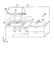
- FIG. 1 is a perspective view of the cooking device 1 according to the first embodiment of the present disclosure.
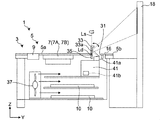
- FIG. 2 is a structural explanatory view of the cooking cooker 1 according to the first embodiment.
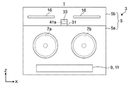
- FIG. 3 is a top view of the cooking utensil 1 according to the first embodiment.
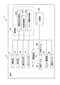
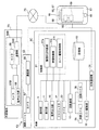
- FIG. 4 is a block diagram showing a control system of the cooking cooker 1.
- the X-axis direction indicates the width direction of the cooker
- the Y-axis direction indicates the front-rear direction
- the Z-axis direction indicates the height direction.
- the positive direction of the X-axis is to the right and the negative direction is to the left.
- the cooking cooker 1 is installed in, for example, the system kitchen BK.
- the system kitchen BK includes, for example, a cooker 1, a countertop Ct, a sink SK, and a range hood 17. Further, a wall surface 18 is arranged on the back side of the cooking cooker 1, the countertop Ct, and the sink SK.
- the range hood 17 is attached to the wall surface 18 so as to be located above the cooking cooker 1.
- the range hood 17 sucks the air above the cooking cooker 1 into the inside by a built-in fan and exhausts the air from the discharge port communicating with the outside.
- the wall surface 18A is arranged on the left side facing the cooking cooker 1.
- the system kitchen BK is installed, for example, in an L-shaped corner formed by the wall surfaces 18 and 18A.
- the cooking cooker 1 includes a main body 3 and a top unit 5 as an upper portion of the main body 3.
- the top unit 5 has a top plate 5a on which a cooking container is placed, and a back frame 5b arranged on the back side (Y direction side) of the top plate 5a.
- the back frame 5b is provided with an exhaust port 16.
- the container contains the object to be cooked.
- the cooking cooker 1 is an induction cooking cooker.
- the cooking cooker 1 includes a heating unit 7 and a circuit board 10 below the container mounting area on the top plate 5a and inside the main body 3.
- the heating unit 7 includes heating coils 7A and 7B.
- the heating coils 7A and 7B generate an induced magnetic field to heat the vessel.
- the circuit board 10 supplies high-frequency current to the heating coils 7A and 7B, and controls the amount of current flowing through the heating coils 7A and 7B.
- the main body 3 includes an operation unit 9 for the user to operate the heating unit 7.
- the operation unit 9 is arranged on the front side of the top plate 5a of the cooking cooker 1.
- the operation unit 9 is, for example, a touch key, a touch panel, a dial, a button, a lever, or the like.
- the circuit board 10 controls the start, stop, and thermal power level of heating of the heating coils 7A and 7B in response to the operation instruction of the operation unit 9.
- the main body 3 includes a display unit 11 that displays information such as the thermal power level from the heating unit 7 by characters or images, and a voice output unit 15 that notifies information about heating of the heating unit 7 by voice.
- the display portion 11 is arranged on the front side of the top plate 5a of the cooking cooker 1.
- the display unit 11 is, for example, a black-and-white liquid crystal panel having a band shape extending in the longitudinal direction of the top plate 5a, but may be a color liquid crystal panel.
- the display unit 11 and the operation unit 9 are integrated as a touch panel.
- the cooking cooker 1 is provided with a voice output unit 15 on the front side for outputting voice guidance to the user.
- the audio output unit 15 is, for example, a speaker.
- a through hole 31 is provided in the central portion of the back frame 5b in the longitudinal direction.
- the through hole 31 is covered with a biaxially rotatable cover 33 that can be opened and closed.
- the cover 33 is rotationally driven by the cover drive unit 35 around the first rotation axis Ld extending in the longitudinal direction (X direction) and around the second rotation axis Ls extending in the vertical direction (Z direction).
- the first rotation shaft Ld is arranged on the front side of the cover 33.
- the closed cover 33 is rotationally driven so as to stand up from the back side to the front side, so that the light of the projector 41 described later is less likely to enter the user's eyes directly.
- cooking stains are less likely to adhere to the projector 41.
- the cover drive unit 35 includes, for example, a two-axis rotation mechanism and a stepping motor.
- the inner surface 33a of the cover 33 is mirror-finished.
- the cooking cooker 1 is provided with a projector 41 inside the main body 3.
- the projector 41 is arranged below the top plate 5a and the cover 33.
- An image is emitted from the projection lens 41a of the projector 41 toward the inner surface 33a of the cover 33.
- the irradiated image is reflected by the inner surface 33a of the cover 33 and projected on the wall surface 18 between the range hood 17 and the cooking cooker 1.
- the projection lens 41a is, for example, a zoom lens, and the projector 41 has a zoom adjustment mechanism (not shown) of the projection lens 41a, and the zoom adjustment mechanism is the projection lens 41a in response to an operation from the operation unit 9.
- the projection magnification may be adjusted.
- the cooking cooker 1 is provided with a fan 37 inside the main body 3.
- the wind generated by the fan 37 cools the circuit board 10 and also cools the light source portion 41b of the projector 41.
- the light source unit 41b is, for example, an LED or a laser.
- the air that has cooled the circuit board 10 and the projector 41 flows to the outside of the cooking cooker 1 through the exhaust port 16.
- the cooking cooker 1 includes a control unit 51 and a storage unit 53.
- the storage unit 53 stores video content and audio information corresponding to the cooking program.
- the control unit 51 can be realized by a semiconductor element or the like.
- the control unit 51 is a processing device composed of, for example, a microcomputer, a CPU, a microprocessor, a DSP, an FPGA, an ASIC, or the like.
- the control unit 51 may be configured only with hardware, or may be realized by combining hardware and software.
- the control unit 51 is configured to perform various functions by reading and executing data and programs stored in a storage unit 53 such as a ROM, RAM, hard disk, and SSD.
- the control unit 51 includes a cooking status determination unit 51a, a video control unit 51b, and a cover drive control unit 51c.
- the cooking status determination unit 51a determines the cooking status on the top plate 5a and controls the progress of the cooking program according to the cooking status.
- the cooking program includes each cooking step required to cook one dish, and each cooking step includes cooking information such as cooking content, heating amount and heating time.
- a plurality of types of cooking programs are stored in the storage unit 53.
- the cooking status is, for example, the cooking process currently being executed.
- the amount of heating is at least one of thermal power and heating temperature.
- a "hamburger" cooking program has a preheating step for preheating a frying pan, a front baking step, an inside out step, a back baking step, and a finishing step.
- Each cooking process has predetermined cooking information such as heating time and heating amount.
- the cooking program is not limited to the cooking process in the cooking device 1, and may include a process such as preparation.
- the process of cutting the ingredients and the process of kneading the meat of the hamburger may be included.
- Video contents corresponding to these cooking programs are stored in the storage unit 53.
- the image of the hamburger steak as a sample is stored, and in the process of kneading, the image of the hamburger steak before being baked is stored.
- the cooking status determination unit 51a reads the corresponding cooking program from the storage unit 53 based on the input signal from the operation unit 9. Further, based on the input signal from the operation unit 9, the cover drive control unit 51c drives and controls the cover drive unit 35 to rotate the cover 33 in an upright state.
- the cooking status determination unit 51a determines the progress of the cooking process based on the read cooking program and the output of the circuit board 10. Information on the cooking process is sent to the video control unit 51b, and the video control unit 51b selects and reads out the video content corresponding to the cooking process from the storage unit 53 and sends it to the projector 41. In this way, the video control unit 51b controls the selection and reproduction of the video content, and changes the display of the video content according to the cooking situation.
- the projector 41 reflects the image of the read image content on the cover 33 and projects it on the wall surface 18.
- the cover drive control unit 51c rotates the cover 33 around the second rotation axis Ls extending in the direction perpendicular to the top plate 5a according to the video content.
- the video content includes information on the video direction in advance, and the cover 33 is covered so as to face the wall surface 18 on the counter side Ct side according to this information.
- the drive control unit 51c controls the cover drive unit 35. As a result, the image of "preparation" shifts to the countertop Ct side, making it easier for the user standing in front of the countertop Ct to see.
- the content is, for example, the content of the video content corresponding to each cooking process. Further, in the cooking process in which the back wall surface 18 of the cooking cooker 1 becomes difficult to see due to steam from the container, such as after removing the lid, the cover 33 is rotated to the side wall surface 18A side of the cooking cooker 1.
- the cover drive control unit 51c controls the cover drive unit 35 so as to do so. For example, information on the image direction is stored in the storage unit 53 for each cooking process in advance, and when the cooking status determination unit 51a detects that the lid has been removed, the detection result and the storage unit 53 store the information.
- the cover drive control unit 51c controls the drive amount of the cover drive unit 35 based on the information regarding the image direction.
- the video content can be projected on the wall surface 18A on the side surface of the cooking cooker 1.
- the direction in which the video content is projected may be automatically set by the video control unit 51b, or may be set by the user via the operation unit 9.
- the image control unit 51b adjusts the projected image content in order to correct the deformation of the projected image caused by the rotation of the cover 33 according to the rotation drive amount instructed by the cover drive control unit 51c to the cover drive unit 35. ..
- a cover 33 may be adopted as a projection direction changing unit for changing the projection direction of the image projected from the projector 41, a cover 33 and a cover driving unit 35 may be formed, or the cover 33 and the cover 33. It may be composed of a cover drive unit 35 and a cover drive control unit 51c.
- the cooking status determination unit 51a determines that all the cooking processes have been completed, the cooking status determination unit 51a turns off the power of the projector 41. Further, the cover drive control unit 51c controls the cover drive unit 35 so as to close the cover 33. This ends the projection of the video content.
- the top plate 5a on which the container for accommodating the object to be heated is placed and the heating unit 7 for heating the container placed on the top plate 5a from below.
- the projector 41 is arranged below the top plate 5a and projects an image obliquely upward. Since the projector 41 is housed below the top plate 5a of the cooking cooker 1, it is possible to provide a cooking cooker capable of displaying video contents and easy to install. Further, by using the projector 41 for displaying the video content, the space around the cooking cooker 1 is not narrowed even if the projection size of the video content is increased, so that the video content can be easily viewed by the user while saving space. be able to.
- the cooking cooker 1A according to the second embodiment includes various sensors, and changes the projection direction of an image according to the detection result of each sensor.
- the cooking cooker 1A in the second embodiment has the same configuration as the cooking cooker 1 in the first embodiment except for the items described below.
- the motion sensors 27 and 28 for detecting the position of the user, the temperature sensor 29 for detecting the temperature of the container or the cooking object in the container, and the main body communication unit 39 for wireless communication are performed.
- the control unit 51 of the second embodiment has a voice recognition unit 51d.
- the motion sensors 27 and 28 are, for example, proximity sensors, and detect the presence of a user (person) within a short distance from the motion sensors 27 and 28.
- the motion sensor 27 is arranged on the front side of the main body 3.
- the motion sensor 28 is arranged, for example, on the front side of the countertop Ct.
- the motion sensors 27 and 28 can detect a user in front of the cooking cooker 1B and a user in front of the countertop Ct.
- the detection signals of the motion sensors 27 and 28 are transmitted to the control unit 51.
- the motion sensors 27 and 28 consume a relatively large amount of energy. When it is arranged in the main body 3 like the motion sensor 27, energy is supplied from the power source of the cooking cooker 1, so that the operation can be performed stably.
- the cover drive control unit 51c controls the cover drive control unit 35 so as to project an image on the wall surface 18 on the back side of the cooking cooker 1 when a detection signal indicating the presence of the user is input from the motion sensor 27. .. Further, when a detection signal indicating the presence of the user is input from the motion sensor 28, the cover drive unit 35 is controlled so as to project an image on the wall surface 18 on the back side of the countertop Ct. In this way, the cover drive control unit 51c changes the projection direction of the image by controlling the rotation drive amount of the cover 33 according to the position of the user.
- the temperature sensor 29 is arranged at the center of the heating coils 7A and 7B below the top plate 5a, for example, in order to detect the temperature at the bottom of the container.
- the detected temperature of the temperature sensor 29 is transmitted to the control unit 51.
- an infrared sensor may be attached to the range hood 17 to detect the temperature of the cooked food in the container and the temperature of the container.
- the photographing unit 55 includes a camera 57, a main body communication unit 39 of the main body 3, and a communication unit 59 that transmits and receives data by wireless communication.
- the camera 57 can photograph the surroundings of the top plate 5a and the top plate 5a.
- the camera 57 may be, for example, a visible light camera or a thermal image camera.
- the image information captured by the camera 57 is sent from the communication unit 59 to the control unit 51 via the main body communication unit 39 of the main body 3.
- the cover drive control unit 51c projects the video content on the wall surface 18 at the back of the cooking cooker 1.
- the cover drive control unit 51c drives the cover drive unit 35 so that the video content is projected on the wall surface 18 behind the countertop Ct. Control the amount to change the projection position. In this way, the cover drive control unit 51c changes the projection direction of the image according to the position of the user based on the detection result by the motion sensor.
- the video control unit 51b projects the video content of the next cooking program based on this determination result. If the next video content is, for example, cooking with the lid of the container open, it may not be visible due to steam, so the cooking status determination unit 51a drives the cover according to the progress of the cooking program.
- the control unit 51c is instructed to change the projection position.
- the cover drive control unit 51c controls the drive amount of the cover drive unit 35 to rotate the cover 33 according to the instruction of the cooking status determination unit 51a. In this way, the cover drive control unit 51c changes the projection direction of the image according to the cooking situation.
- the cover drive control unit 51c changes the projection direction by controlling the drive amount of the cover drive unit 35 according to the operation amount received by the operation unit 9 according to the user's instruction to the operation unit 9 as the instruction receiving unit. You may. Further, the projection direction may be changed according to the voice instruction of the user. For example, the user's voice is collected by the microphone 45 as an instruction receiving unit, and the collected voice information is sent to the voice recognition unit 51d. The voice recognition unit 51d recognizes the user's instruction from the voice information and transmits the recognized user's instruction to the cover drive control unit 51c. In this way, the cover drive control unit 51c may change the projection direction by controlling the drive amount of the cover drive unit 35 based on the user's instruction.
- the projection direction is changed according to the detection results of various sensors.
- the cooking cooker 1A may include all of the motion sensors 27 and 28, the temperature sensor 29, the microphone 45, and the photographing unit 55, or may include any one of them.
- a blowout sensor may be provided to control the projector 41 so that the image control unit 51b pauses the projection of the video content when the blowout is detected.
- the projection direction may be changed according to the image information captured by the camera 57.
- the cooking status determination unit 51a may detect steam from the image information captured by the camera 57 and change the projection direction.
- the projection may be paused according to the image information captured by the camera 57.
- the cooking status determination unit 51a may detect a spill from the image information captured by the camera 57 and change the projection direction.
- the cooking cooker 1B according to the third embodiment can access the mobile terminal 61 and download the cooking program and the video content via the mobile terminal 61.
- the cooking cooker 1B in the third embodiment has the same configuration as the cooking cooker 1 of the first embodiment except for the items described below.
- the cooking cooker 1B of the third embodiment includes a main body communication unit 39 and wirelessly communicates with the mobile terminal 61.
- the main body communication unit 39 and the terminal communication unit 63 of the mobile terminal 61 each have an antenna, for example, Wi-Fi (registered trademark), Bluetooth (registered trademark), BLE (Bluetooth (registered trademark) Low Energy), or 5G. It is connected by wireless communication of standards such as.
- the mobile terminal 61 is, for example, a smartphone or a tablet type terminal. It includes a terminal communication unit 63 that wirelessly communicates with the cooking cooker 1B, an operation unit 65, a voice output unit 66, a display unit 67, a storage unit 68, and a terminal control unit 69 that controls these.
- the terminal communication unit 63 is also communicably connected to the server 71 via the Internet 70 or the like by wireless communication.
- the audio output unit 66 is, for example, a speaker.
- the display unit 67 is, for example, a touch panel display, and may have the function of the operation unit 65.
- the terminal control unit 69 is, for example, a processing device such as a CPU or a microprocessor, and performs various functions by executing an application program stored in a storage unit 68 such as a ROM, a RAM, a hard disk, or an SSD. It is configured.
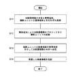
- FIG. 8 is a flowchart showing a processing procedure for projecting the video content of the cooking menu downloaded from the server.
- step S1 the cooking cooker 1B and the mobile terminal 61 are wirelessly connected. Bidirectional communication is possible between the main body communication unit 39 of the cooking cooker 1B and the terminal communication unit 63 of the mobile terminal 61.
- the application software for the cooking cooker 1B is preliminarily incorporated in the mobile terminal 61 by downloading or the like. By activating this application software, the user can operate the cooking cooker 1B by the operation unit 65 of the mobile terminal 61.
- the user instructs the start of the projector 41 by using the operation unit 65 of the mobile terminal 61.
- the start signal is input from the operation unit 65 to the video control unit 51b via the terminal communication unit 63 and the main body communication unit 39.
- the image control unit 51b starts the projector 41 by the input start signal.
- the mobile terminal 61 is connected to the server 71 via the Internet 70.
- Various cooking menus are stored in the server 71.
- the user downloads the data of the favorite cooking menu from the server 71 to the mobile terminal 61 by using the application software of the mobile terminal 61, and stores the data in the storage unit 68.
- step S4 the cooking menu data downloaded to the mobile terminal 61 is transmitted from the mobile terminal 61 to the cooking cooker 1B.
- the cooking cooker 1B stores the received cooking menu data in the storage unit 53.
- step S5 the image control unit 51b transmits the image content corresponding to each cooking process of the cooking menu to the projector 41, and the projector 41 projects the image content on the wall surface 18.
- the download from the server 71 is not limited to the cooking menu information, and only the video content may be downloaded.
- the downloaded video content is sent to the video control unit 51b, and the user's favorite video content can be projected from the projector 41.
- the cooking cooker 1B of the third embodiment since the cooking cooker 1B can download the favorite cooking menu from the server 71 through the Internet 70, the projected video content can be increased. Moreover, not only the video content related to the cooking menu but also other favorite video contents can be downloaded, so that the cooking can be done while viewing the favorite video contents.
- the cooking cooker 1C according to the fourth embodiment accesses the mobile terminal 61 and the photographing unit 55A, and projects the image of the camera 57 on the wall surface 18.
- the photographing unit 55 of the second embodiment is arranged around the cooking cooker 1B such as the range hood 17, but the photographing unit 55A of the fourth embodiment is arranged in the living room or another room.
- the cooking cooker 1C in the fourth embodiment has the same configuration as the cooking cooker 1A of the second embodiment and the cooking cooker 1B of the third embodiment except for the items described below.
- the cooking cooker 1C is provided with a microphone 23 that collects the voice of the cook.
- the microphone 23 is arranged on the front surface of the main body 3.
- the voice information collected by the microphone 23 is transmitted from the main body communication unit 39 to the photographing unit 55A via, for example, the mobile terminal 61.
- the heating cooker 1C, the mobile terminal 61, and the photographing unit 55A are each connected to a wireless communication network such as a wireless LAN, and the heating cooker 1C and the photographing unit 55A can directly transmit and receive video and audio information. It may be.
- the photographing unit 55A includes a camera 57, a microphone 56, an audio output unit 58, and a communication unit 59.
- the video image taken by the camera 57 and the sound collected by the microphone 56 are transmitted from the communication unit 59 to the main body 3 of the cooking cooker 1C via the mobile terminal 61.
- FIG. 10 is a flowchart showing a processing procedure in which the photographing unit projects a photographed image photographed by 55A.
- step S11 the cooking cooker 1C and the mobile terminal 61 are wirelessly connected. Bidirectional communication is possible between the main body communication unit 39 of the cooking cooker 1C and the terminal communication unit 63 of the mobile terminal 61. Further, the photographing unit 55A and the mobile terminal 61 are wirelessly connected. Bidirectional communication is possible between the third communication unit 77 of the photographing unit 55A and the terminal communication unit 63 of the mobile terminal 61.
- Application software for the main body 3C and the shooting unit 55A is preliminarily incorporated in the mobile terminal 61 by downloading or the like. By activating this application software, the user can operate the main body 3C and the photographing unit 55A by the operation unit 65 of the mobile terminal 61.
- step S12 the user instructs the start of the projector 41 by using the operation unit 65 of the mobile terminal 61.
- An activation signal is input from the operation unit 65 of the mobile terminal 61 to the video control unit 51b via the terminal communication unit 63 and the main body communication unit 39.
- the image control unit 51b starts the projector 41 by the input start signal.
- the user instructs the activation of the photographing unit 55A by using the operation unit 65 of the mobile terminal 61.
- An activation signal is transmitted from the operation unit 65 of the mobile terminal 61 to the photographing unit 55A via the terminal communication unit 63 and the communication unit 59, and the photographing unit 55A is activated.
- the photographing unit 55A transmits the video information of the camera 57 and the audio information of the microphone 56 to the cooking cooker 1D via the mobile terminal 61.
- the main body 3C, the photographing unit 55A, and the mobile terminal 61 may directly transmit and receive video and audio information between the main body 3C and the photographing unit 55A by, for example, a plurality of simultaneous connections at multiple points.
- step S14 the video control unit 51b of the cooking cooker 1D sends the received video information to the projector 41.
- the projector 41 projects the received video information onto the wall surface 18.
- the video control unit 51b of the cooking cooker 1D sends the received audio information to the speaker 76, and the audio of the place where the photographing unit 55A is installed flows from the speaker 76.
- the user can see the photographed image of the place where the photographing unit 55A is installed while being in front of the cooking device 1C.
- the photographing unit 55A in, for example, a living room with a child or a bedroom with a long-term care recipient, cooking can be performed while observing the state of the child or the long-term care recipient.
- the cooking unit 1 and the photographing unit 55A can have a two-way conversation by voice, the cook's voice is heard from the photographing unit 55A when the cook speaks, and the child and the person requiring nursing care are relieved. be able to.
- the cooking cooker 1D according to the fifth embodiment is a cooker 1D capable of accessing the photographing unit 55B of the external terminal 73 via the mobile terminal 61 and the Internet 70 and communicating with an outside person through the photographing unit 55B. ..
- the cooking cooker 1D in the fifth embodiment has the same configuration as the cooking cookers 1 to 1C of the first to fourth embodiments, except for the items described below.
- the cooking cooker 1D includes a photographing unit 55 that photographs a cook (user).
- the camera 57 may be arranged at the center of the hood portion 17a of the range hood 17 or may be arranged on the wall surface 18 as in the second embodiment.
- the camera 57 is arranged so that, for example, in addition to the cook, the container placed on the top plate 5a and the object to be cooked are within the angle of view.
- the external terminal 73 may be, for example, a PC, a mobile tablet, or a mobile terminal.
- the external terminal 73 includes a photographing unit 55B.
- the photographing unit 55B includes a camera 57B, a microphone 56, an audio output unit 58, and a communication unit 59B.
- the external terminal 73 may be arranged, for example, in a cooking class or in a family home living apart.
- the cooker 1D allows an outsider to see the cook's cooked food through the Internet 70, and the cooker can also see the cooked food cooked by the outsider.
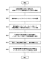
- FIG. 12 is a flowchart showing a procedure for processing an image of a cooking cooker that communicates with an external terminal.
- step S21 the cooking cooker 1D and the mobile terminal 61 are wirelessly connected. Bidirectional communication is possible between the main body communication unit 39 of the cooking cooker 1D and the terminal communication unit 63 of the mobile terminal 61. Further, the photographing unit 55 and the mobile terminal 61 are wirelessly connected. Further, the external photographing unit 55B and the mobile terminal 61 are connected via the Internet 70. Bidirectional communication is possible between the communication unit 59B of the photographing unit 55B and the terminal communication unit 63 of the mobile terminal 61.
- Application software for the cooking cooker 1D and the photographing unit 55 is preliminarily incorporated in the mobile terminal 61 by downloading or the like. By activating this application software, the user can operate the cooking cooker 1D and the camera 57 of the photographing unit 55A by the operation unit 65 of the mobile terminal 61.
- step S22 the user instructs the start of the projector 41 by using the operation unit 65 of the mobile terminal 61.
- the start signal is input from the operation unit 65 to the video control unit 51b via the terminal communication unit 63 and the main body communication unit 39.
- the image control unit 51b starts the projector 41 by the input start signal.
- the user instructs the activation of the camera 57 of the photographing unit 55 by using the operation unit 65 of the mobile terminal 61.
- An activation signal is transmitted from the operation unit 65 to the camera 57 via the terminal communication unit 63 and the communication unit 59, and the camera 57 is activated.
- step S23 the heating cooker 1D and the photographing unit 55B of the external terminal 73 are connected via the Internet 70 by the mobile terminal 61.
- step S24 the external terminal 73 transmits the video information taken by the camera 57B and the audio information collected by the microphone 56 to the mobile terminal 61 via the Internet 70.
- the mobile terminal 61 transmits the received video information and audio information to the cooking cooker 1D.
- step S25 the video control unit 51b of the cooking cooker 1D sends the received video information to the projector 41.
- the projector 41 projects the received video information onto the wall surface 18.
- the video control unit 51b of the cooking cooker 1D sends the received audio information to the audio output unit 15, and the audio of a person in front of the external terminal 73 flows from the audio output unit 15. Therefore, the cook can see the video of the cooking procedure of the teacher in the cooking class while being in front of the cooking cooker 1, and can be taught the cooking method.
- the cooked food of the user can be shown to the teacher in the cooking class. It is also possible for the cook and the teacher in the cooking class to have a conversation.
- the image control unit 51b synthesizes the image information received from the external terminal 73 and the images of the cook and the object to be heated taken by the photographing unit 55 of the cooking device 1D, and for example, a combined image such as a wipe image. May be projected from the projector 41.
- the cooking device 1D of the fifth embodiment since it is connected to the external terminal 73 via the Internet 70, it is possible to see the person in front of the external terminal 73 and the cooking scenery, and to have a conversation. It is also possible to show the user in front of the cooker 1D and the cooking status on the top plate 5a to the person in front of the external terminal 73.
- the video content is projected on the wall, but the present invention is not limited to this.
- a screen 19 may be provided.
- the screen 19 may be, for example, a roll screen made of cloth, or a disposable screen that can be replaced when it becomes dirty with oil. If it is difficult to see the image due to the color of the wall surface, a white screen may be attached to the wall surface.
- one surface is a light diffusing layer and the other surface is an adhesive layer.
- the screen 19 includes at least a light reflecting layer between the light diffusing layer and the adhesive layer.
- the projector 41 reflects the image on the cover 33 and projects it, but the present invention is not limited to this.
- the projector 41 may directly project the image onto the cover 33 without reflecting it.
- the back frame 5b or the top plate 5a of the top unit 5 may be transmitted and directly projected.
- the back frame 5b or the top plate 5a through which the video content is transmitted is a colorless and transparent member, for example, tempered glass.
- the projection direction may be rotated by making the projector 41 itself rotatable.
- a cover glass different from that of the top plate 5a may be fitted into the back frame 5b or the top plate 5a, and light may be transmitted through the cover glass to project an image.
- a part of the projector 41 for example, a projection lens 41a may be projected from the back frame 5b or the top plate 5a, and light may be projected directly from the protruding portion toward the wall surface 18.
- the protruding portion may be rotatable about a vertical axis or may be vertically movable up and down.
- the protruding portion may be covered with a dome-shaped or tubular cover.
- the dome-shaped or tubular cover may be configured to transmit light in part or in whole.
- the video content stored in the storage unit 53 is not limited to the video related to cooking.
- the video content may be other video, such as a landscape or outdoor video. Further, the user may be able to directly select the video content by the operation unit 9.
- the video also includes still images and moving images.
- the heating cooker 1 is an induction heating cooker that induces and heats a container by using heating coils 7A and 7B, but the present invention is not limited to this.
- the cooking cooker 1 may be a gas cooker.
- the container is placed on the trivet as a container mounting portion provided on the top plate 5a of the main body 3, and is heated from below by a gas burner as a heating portion.
- the number of projectors 41 is one, but there may be a plurality of projectors 41. Further, there may be a plurality of light guide paths for one projector 41.
- the projection direction of the image is changed significantly, it may be difficult to correct the keystone of the projected image.
- the projector 41 may be a CRT system or a liquid crystal system, or may be a head-up display.
Landscapes
- Engineering & Computer Science (AREA)
- Multimedia (AREA)
- Signal Processing (AREA)
- Chemical & Material Sciences (AREA)
- Combustion & Propulsion (AREA)
- Mechanical Engineering (AREA)
- General Engineering & Computer Science (AREA)
- Ceramic Engineering (AREA)
- Physics & Mathematics (AREA)
- Electromagnetism (AREA)
- Automation & Control Theory (AREA)
- Induction Heating Cooking Devices (AREA)
- Electric Stoves And Ranges (AREA)
Abstract
加熱対象物を収容する容器が載置されるトッププレート(5a)と、トッププレート(5a)に載置された容器を下方から加熱する加熱部(7)と、少なくとも一部がトッププレート(5a)より下方に配置され、斜め上方に向けて映像を投影するプロジェクタ(41)と、を備える、加熱調理器(1)である。
Description
本開示は、加熱調理器に関し、特に映像コンテンツを表示する加熱調理器に関する。
従来、加熱調理器の操作状態を表示する表示部をトッププレート上に備える加熱調理器がある。トッププレート上には、鍋を加熱する加熱領域や、火力を調節する操作部が配置されているので、表示部のサイズには制限がある。したがって、多くの情報を表示することができなかった。そこで、特許文献1の加熱調理器は、液晶モニタを加熱調理器の本体と別体で備える。
例えば、特許文献1の加熱調理器は、別体の液晶モニタにトッププレート上に配置された液晶モニタと同じ情報を表示する。さらに、別体の液晶モニタは、テレビ放送を受信してテレビ番組を表示しながら、加熱調理器の調理情報を表示することもできる。
しかしながら、加熱調理器と液晶モニタとを配置する場合、設置が煩雑になるという課題がある。
したがって、本開示の目的は、前記課題を解決することにあって、映像コンテンツを表示可能で設置が容易な加熱調理器を提供することにある。
前記目的を達成するために、本開示の一態様に係る加熱調理器は、
加熱対象物を収容する容器が載置されるトッププレートと、
前記トッププレートに載置された前記容器を下方から加熱する加熱部と、
少なくとも一部が前記トッププレートより下方に配置され、斜め上方に向けて映像を投影するプロジェクタと、
を備える。
加熱対象物を収容する容器が載置されるトッププレートと、
前記トッププレートに載置された前記容器を下方から加熱する加熱部と、
少なくとも一部が前記トッププレートより下方に配置され、斜め上方に向けて映像を投影するプロジェクタと、
を備える。
映像コンテンツを表示可能で設置が容易な加熱調理器を提供することができる。
本開示の一態様によれば、加熱対象物を収容する容器が載置されるトッププレートと、前記トッププレートに載置された前記容器を下方から加熱する加熱部と、少なくとも一部が前記トッププレートより下方に配置され、斜め上方に向けて映像を投影するプロジェクタと、を備える、加熱調理器である。
また、前記プロジェクタは、ズームレンズを有してもよい。
また、前記トッププレートは開口部を有し、前記開口部を開閉可能に覆うカバーを備えてもよい。
また、前記プロジェクタから投影された映像を水平方向に移動可能な投影方向変更部を備えてもよい。
また、前記トッププレートは開口部を有し、前記投影方向変更部は、前記開口部を開閉可能に覆い、かつ、反射面を有するカバーと、前記カバーを2軸回転駆動するカバー駆動部と、を有し、前記プロジェクタは前記カバーの前記反射面に映像を反射させて映像を投影してもよい。
また、前記投影方向変更部は、調理状況に応じて映像の投影方向を変更してもよい。
また、前記容器の温度を検出する温度センサと、前記温度センサの検出温度を基に、調理状況を判断する調理状況判断部と、を備え、前記投影方向変更部は、前記調理状況判断部の判断結果を基に映像の投影方向を変更してもよい。
また、ユーザの存在を検出する人感センサを備え、前記投影方向変更部は、ユーザの位置に応じて、映像の投影方向を変更してもよい。
また、前記投影方向変更部は、映像コンテンツの内容に応じて映像の投影方向を変更してもよい。
また、ユーザの指示を受け付ける指示受信部を備え、前記投影方向変更部は、前記ユーザの指示を基に投影方向を変更してもよい。
また、投影する映像コンテンツの選択および再生を制御する映像制御部を備え、前記映像制御部は、調理状況に応じて、前記映像コンテンツの表示を変更してもよい。
また、携帯端末と無線接続する本体通信部を備え、前記本体通信部は、前記携帯端末と無線接続されるカメラの撮影映像を受信し、前記プロジェクタは、前記撮影映像を投影してもよい。
また、携帯端末と無線接続する本体通信部を備え、前記本体通信部は、前記携帯端末とインターネット接続する外部端末が有するカメラの撮影映像を受信し、前記プロジェクタは、前記撮影映像を投影してもよい。
また、前記プロジェクタから出射された映像が投影されるスクリーンを備えてもよい。
(実施形態1)
以下に、本開示の実施形態1に係る加熱調理器について図1から図4を参照して説明する。図1は、本開示の実施形態1に係る加熱調理器1の斜視図である。図2は、実施形態1に係る加熱調理器1の構造説明図である。図3は、実施形態1に係る加熱調理器1の上面図である。図4は、加熱調理器1の制御系を示すブロック図である。なお、図において、X軸方向は加熱調理器の幅方向を示し、Y軸方向は前後方向を示し、Z軸方向は高さ方向を示す。また、X軸の正の方向を右方、負の方向を左方とする。
以下に、本開示の実施形態1に係る加熱調理器について図1から図4を参照して説明する。図1は、本開示の実施形態1に係る加熱調理器1の斜視図である。図2は、実施形態1に係る加熱調理器1の構造説明図である。図3は、実施形態1に係る加熱調理器1の上面図である。図4は、加熱調理器1の制御系を示すブロック図である。なお、図において、X軸方向は加熱調理器の幅方向を示し、Y軸方向は前後方向を示し、Z軸方向は高さ方向を示す。また、X軸の正の方向を右方、負の方向を左方とする。
図1に示すように、加熱調理器1は、例えば、システムキッチンBKに設置されている。システムキッチンBKは、例えば、加熱調理器1と、調理台Ctと、シンクSKと、レンジフード17と、を備える。また、加熱調理器1、調理台Ct、及びシンクSKの奥側に壁面18が配置されている。レンジフード17は、加熱調理器1の上方に位置するように壁面18に取り付けられている。レンジフード17は、内蔵するファンにより、加熱調理器1の上方の空気を内部に吸い込んで屋外に連通した吐出口から排気する。加熱調理器1に正対して左側に、壁面18Aが配置されている。システムキッチンBKは、例えば、壁面18及び18Aで形成されるL字型のコーナーに設置されている。
図2及び図3に示すように、加熱調理器1は、本体3と、本体3の上側部としてのトップユニット5を備える。トップユニット5は、調理用の容器が載置されるトッププレート5aと、トッププレート5aの奥側(Y方向側)に配置されたバックフレーム5bとを有する。バックフレーム5bには、排気口16が設けられている。また、容器には調理対象物が収容される。
実施形態1の場合、加熱調理器1は、誘導加熱調理器である。加熱調理器1は、トッププレート5aにおける容器載置領域の下方であって本体3の内部に、加熱部7及び回路基板10を備える。加熱部7は、加熱コイル7A及び7Bを備える。加熱コイル7A及び7Bは、容器を加熱するために誘導磁界を発生させる。回路基板10は、加熱コイル7A及び7Bに高周波電流を供給し、また、加熱コイル7A及び7Bに流す電流量を制御する。
本体3は、加熱部7をユーザが操作するための操作部9を備える。操作部9が加熱調理器1のトッププレート5aの前側に配置されている。操作部9は、例えば、タッチキー、タッチパネル、ダイヤル、ボタン、またはレバーなどである。操作部9の操作指示に応じて、回路基板10は、加熱コイル7A及び7Bの加熱の開始、停止及び火力レベルを制御する。
また、本体3は、加熱部7からの火力レベル等の情報を文字または画像により表示する表示部11と、加熱部7の加熱に関する情報を音声により報知する音声出力部15とを備える。表示部11は加熱調理器1のトッププレート5aの前側に配置されている。表示部11は、例えば、トッププレート5aの長手方向に延びる帯形状を有する、白黒の液晶パネルであるが、カラーの液晶パネルでもよい。なお、実施形態1では、表示部11と操作部9とがタッチパネルとして一体化されている。
また、加熱調理器1は、ユーザに対して音声案内を出力する音声出力部15を、前面側に備える。音声出力部15は、例えば、スピーカである。
バックフレーム5bの長手方向中央部に貫通孔31が設けられている。貫通孔31は、2軸回動可能なカバー33に開閉可能に覆われている。カバー33は、カバー駆動部35により、長手方向(X方向)に延びる第1回転軸Ld周りに回転駆動され、垂直方向(Z方向)に延びる第2回転軸Ls周りに回転駆動される。第1回転軸Ldは、カバー33の前側に配置される。これにより、閉じているカバー33が奥側から前側に起立するように回転駆動されるので、後述のプロジェクタ41の光がユーザの目に直接入りにくくなる。また、調理の汚れがプロジェクタ41に付着しにくくなる。カバー駆動部35は、例えば、2軸回転機構とステッピングモータとを備える。カバー33の内面33aは、鏡面加工されている。
加熱調理器1は、本体3の内部にプロジェクタ41を備える。プロジェクタ41は、トッププレート5a及びカバー33の下方に配置されている。プロジェクタ41の投光レンズ41aからカバー33の内面33aに向けて映像が照射される。照射された映像は、カバー33の内面33aで反射してレンジフード17と加熱調理器1との間の壁面18に投影される。投光レンズ41aは、例えばズームレンズであり、プロジェクタ41は、投光レンズ41aのズーム調整機構(図示省略)を有し、操作部9からの操作に応じてズーム調整機構が投光レンズ41aの投影倍率を調整してもよい。
加熱調理器1は、本体3の内部にファン37を備える。ファン37が生成する風は、回路基板10を冷却すると共に、プロジェクタ41の光源部41bも冷却する。光源部41bは、例えば、LED又はレーザである。回路基板10およびプロジェクタ41を冷却した風は、排気口16を通って加熱調理器1の外部へ流れる。
加熱調理器1は、制御部51及び記憶部53を備える。記憶部53には、調理プログラムに対応した映像コンテンツ及び音声情報が記憶されている。
制御部51は、半導体素子などで実現可能である。制御部51は、例えばマイコン、CPU、マイクロプロセッサ、DSP、FPGA、またはASICなどで構成される処理装置である。制御部51は、ハードウェアのみで構成してもよいし、ハードウェアとソフトウェアとを組み合わせることにより実現してもよい。制御部51は、ROM、RAM、ハードディスク、SSDなどの記憶部53に記憶されているデータやプログラムを読み出して実行することによって種々の機能を果たすように構成されている。
制御部51は、調理状況判断部51aと、映像制御部51bと、カバー駆動制御部51cとを有する。
調理状況判断部51aは、トッププレート5a上の調理状況を判断し、調理状況に応じて調理プログラムの進行を制御する。調理プログラムは、1つの料理を調理するために必要な各調理工程を含み、各調理工程は、調理内容、加熱量及び加熱時間等の調理情報を含む。複数種類の調理プログラムが記憶部53に記憶されている。調理状況とは、たとえば現在実行中の調理工程である。加熱量とは、火力および加熱温度の少なくとも一方である。
例えば、「ハンバーグ」の調理プログラムの場合、フライパンを予熱する予熱工程、表を焼く工程、裏返し工程、裏を焼く工程、及び終了工程を有する。それぞれの調理工程において、加熱時間及び加熱量等の決められた調理情報を有する。なお、調理プログラムは、加熱調理器1における調理工程だけに限らず、下ごしらえ等の工程も含めてもよい。例えば、「ハンバーグ」の調理プログラムの場合、材料を切る工程や、ハンバーグの肉だねをこねる工程を含めてもよい。
これらの調理プログラムに対応する映像コンテンツが記憶部53に記憶されている。例えば、表を焼く工程では、見本となる焼き色のハンバーグの映像が記憶され、こねる工程では焼かれる前のハンバーグの映像が記憶されている。
ユーザが任意の調理メニューを操作部9を用いて選択すると、操作部9からの入力信号に基づいて調理状況判断部51aは、対応する調理プログラムを記憶部53から読み出す。また、操作部9からの入力信号に基づいて、カバー駆動制御部51cは、カバー駆動部35を駆動制御して、カバー33を起立状態に回転させる。
調理状況判断部51aは、読み出した調理プログラムおよび回路基板10の出力などに基づいて、調理工程の進行を判断する。調理工程の情報は、映像制御部51bに送られ、映像制御部51bは、調理工程に対応する映像コンテンツを記憶部53から選択して読み出して、プロジェクタ41へ送る。このように、映像制御部51bは、映像コンテンツの選択および再生を制御し、調理状況に応じて、映像コンテンツの表示を変更する。
プロジェクタ41は、読み出した映像コンテンツの映像をカバー33に反射させて壁面18へ投影する。なお、映像コンテンツに応じて、カバー駆動制御部51cは、カバー33をトッププレート5aに垂直方向に延びる第2回転軸Ls周りに回転させる。例えば、映像コンテンツの内容が「下ごしらえ」の映像である場合、予め映像コンテンツに映像方向に関する情報が含まれており、この情報にしたがって、カバー33を調理台Ct側の壁面18を向くようにカバー駆動制御部51cがカバー駆動部35を制御する。これにより、「下ごしらえ」の映像が調理台Ct側へ移行して、調理台Ct前に立つユーザに見やすくなる。なお、コンテンツの内容とは、たとえば各調理工程に対応する映像コンテンツの内容である。また、蓋を外した後など、容器からの湯気等で加熱調理器1の奥の壁面18が見えにくくなる調理工程である場合、カバー33を加熱調理器1の横側の壁面18A側に回転するようにカバー駆動制御部51cがカバー駆動部35を制御する。例えば、予め調理工程ごとに映像方向に関する情報が記憶部53に記憶されていることで、調理状況判断部51aが蓋が外れたことを検出すると、この検出結果と記憶部53に記憶されている映像方向に関する情報を基に、カバー駆動制御部51cがカバー駆動部35の駆動量を制御する。これにより、加熱調理器1の横側の壁面18Aに映像コンテンツを投影することができる。映像コンテンツを投影する方向は、映像制御部51bにより自動で設定されてもよく、ユーザにより操作部9を介して設定されてもよい。映像制御部51bは、カバー駆動制御部51cがカバー駆動部35に指示する回転駆動量に応じて、カバー33の回転により発生する投影像の変形を修正するために、投影する映像コンテンツを調整する。なお、プロジェクタ41から投影された映像の投影方向を変更する投影方向変更部として、カバー33を採用してもよいし、カバー33とカバー駆動部35とで構成してもよいし、カバー33とカバー駆動部35とカバー駆動制御部51cとで構成してもよい。
調理状況判断部51aが全ての調理工程を終了したと判断すると、調理状況判断部51aはプロジェクタ41の電源をOFFにする。また、カバー駆動制御部51cは、カバー33を閉じるようにカバー駆動部35を制御する。これにより、映像コンテンツの投影が終了される。
このように実施形態1の加熱調理器1によれば、加熱対象物を収容する容器が載置されるトッププレート5aと、トッププレート5aに載置された容器を下方から加熱する加熱部7と、トッププレート5aより下方に配置され、斜め上方に向けて映像を投影するプロジェクタ41と、を備える。加熱調理器1のトッププレート5aの下方にプロジェクタ41が収容されているので、映像コンテンツを表示可能で設置が容易な加熱調理器を提供することができる。また、映像コンテンツの表示にプロジェクタ41を用いることで、映像コンテンツの投影サイズを拡大しても加熱調理器1の周辺の空間が狭くなることがないので、映像コンテンツを省スペースながらユーザに見やすくすることができる。
(実施形態2)
次に、実施形態2に係る加熱調理器1Aについて図5及び図6を参照して説明する。実施形態2に係る加熱調理器1Aは、種々のセンサを備え、各センサの検出結果に応じて映像の投影方向を変える。なお、実施形態2における加熱調理器1Aは、以下に記載した事項以外の構成は、実施形態1の加熱調理器1と共通である。
次に、実施形態2に係る加熱調理器1Aについて図5及び図6を参照して説明する。実施形態2に係る加熱調理器1Aは、種々のセンサを備え、各センサの検出結果に応じて映像の投影方向を変える。なお、実施形態2における加熱調理器1Aは、以下に記載した事項以外の構成は、実施形態1の加熱調理器1と共通である。
実施形態2の加熱調理器1Aは、ユーザの位置を検知する人感センサ27、28と、容器または容器内の調理対象物の温度を検出する温度センサ29と、無線通信を行う本体通信部39と、マイク45と、撮影ユニット55と、を備える。また、実施形態2の制御部51は、音声認識部51dを有する。
人感センサ27、28は、例えば、近接センサであり、人感センサ27、28から近距離内にユーザ(人)の存在を検出する。人感センサ27は、本体3の前面側に配置されている。人感センサ28は、例えば、調理台Ctの前側に配置されている。人感センサ27、28により、加熱調理器1Bの前にいるユーザと、調理台Ctの前にいるユーザを検出することができる。人感センサ27、28の検出信号は、制御部51へ送信される。なお、人感センサ27、28は、エネルギー消費量が比較的大きい。人感センサ27のように本体3に配置されている場合は、加熱調理器1の電源からエネルギーが供給されるため、安定して動作できる。
カバー駆動制御部51cは、人感センサ27からユーザの存在を示す検出信号が入力されると、加熱調理器1の奥側の壁面18に映像を投影するように、カバー駆動部35を制御する。また、人感センサ28からユーザの存在を示す検出信号が入力されると、調理台Ctの奥側の壁面18に映像を投影するように、カバー駆動部35を制御する。このように、カバー駆動制御部51cは、ユーザの位置に応じて、カバー33の回転駆動量を制御することで、映像の投影方向を変更する。
温度センサ29は、例えば、容器の底の温度を検出するために、トッププレート5aの下方の加熱コイル7A及び7Bの中心に配置される。温度センサ29の検出温度は、制御部51へ送信される。なお、温度センサ29として、赤外線センサをレンジフード17に取り付けて、容器内の調理物の温度及び容器の温度を検出してもよい。
撮影ユニット55は、カメラ57と、本体3の本体通信部39と無線通信によりデータの送受信を行う通信部59と、を備える。撮影ユニット55は、例えば、レンジフード17に配置されることで、カメラ57がトッププレート5aおよびトッププレート5aの周囲を撮影することができる。
カメラ57は、例えば、可視光カメラでもよいし、熱画像カメラでもよい。カメラ57が撮影した画像情報は、通信部59から本体3の本体通信部39を経て、制御部51へ送られる。
人感センサ27により加熱調理器1の前にいるユーザを検出した場合、カバー駆動制御部51cは、加熱調理器1の奥の壁面18に映像コンテンツを投影する。また人感センサ28により調理台Ctの前にいるユーザを検出した場合、カバー駆動制御部51cは、調理台Ctの奥の壁面18に映像コンテンツが投影されるように、カバー駆動部35の駆動量を制御して投影位置を変更する。このように、カバー駆動制御部51cは、人感センサによる検出結果を基に、ユーザの位置に応じて映像の投影方向を変更する。
温度センサ29の検出温度を基に、調理状況判断部51aは調理状況が変化したと判断すると、この判断結果を基に、映像制御部51bは、次の調理プログラムの映像コンテンツを投影する。次の映像コンテンツが、例えば、容器の蓋を開けた状態で調理する内容の場合、湯気で見えない可能性があるので、調理状況判断部51aは、調理プログラムの進行状況に応じて、カバー駆動制御部51cに投影位置を変更するように指示する。カバー駆動制御部51cは、調理状況判断部51aの指示にしたがって、カバー駆動部35の駆動量を制御してカバー33を回転させる。このように、カバー駆動制御部51cは、調理状況に応じて映像の投影方向を変更する。
また、カバー駆動制御部51cは、指示受信部としての操作部9へのユーザの指示により、操作部9が受け付けた操作量に応じてカバー駆動部35の駆動量を制御して投影方向を変更してもよい。また、ユーザの音声指示により投影方向を変更してもよい。例えば、ユーザの音声を指示受信部としてのマイク45により集音し、集音した音声情報を音声認識部51dへ送る。音声認識部51dは、音声情報からユーザの指示を認識し、カバー駆動制御部51cへ認識されたユーザの指示を送信する。このように、カバー駆動制御部51cは、ユーザの指示に基づきカバー駆動部35の駆動量を制御して投影方向を変更してもよい。
実施形態2の加熱調理器1Aによれば、種々のセンサの検出結果に応じて、投影方向を変更する。加熱調理器1Aは、人感センサ27及び28、温度センサ29、マイク45、撮影ユニット55の全てを備えていてもよいし、いずれか1つを備えていてもよい。また、これらのセンサ以外にも、例えば、吹きこぼれセンサを備えて、吹きこぼれを検出した場合、映像制御部51bが映像コンテンツの投影を一時停止するようにプロジェクタ41を制御してもよい。または、カメラ57が撮影した画像情報に応じて、投影方向を変更してもよい。たとえば、カメラ57が撮影した画像情報から、調理状況判断部51aが湯気を検出し、投影方向を変更してもよい。または、カメラ57が撮影した画像情報に応じて、投影を一時停止してもよい。たとえば、カメラ57が撮影した画像情報から、調理状況判断部51aが吹きこぼれを検出し、投影方向を変更してもよい。
(実施形態3)
次に、実施形態3に係る加熱調理器1Bについて図7を参照して説明する。実施形態3に係る加熱調理器1Bは携帯端末61とアクセスして、携帯端末61を介して調理プログラムおよび映像コンテンツをダウンロードすることができる。なお、実施形態3における加熱調理器1Bは、以下に記載した事項以外の構成は、実施形態1の加熱調理器1と共通である。
次に、実施形態3に係る加熱調理器1Bについて図7を参照して説明する。実施形態3に係る加熱調理器1Bは携帯端末61とアクセスして、携帯端末61を介して調理プログラムおよび映像コンテンツをダウンロードすることができる。なお、実施形態3における加熱調理器1Bは、以下に記載した事項以外の構成は、実施形態1の加熱調理器1と共通である。
実施形態3の加熱調理器1Bは本体通信部39を備え、携帯端末61と無線通信を行う。本体通信部39及び携帯端末61の端末通信部63はそれぞれアンテナを有し、例えば、Wi-Fi(登録商標)、Bluetooth(登録商標)、BLE(Bluetooth(登録商標) Low Energy)、又は、5Gなどの規格の無線通信により接続されている。
携帯端末61は、例えば、スマートフォンやタブレット型端末である。加熱調理器1Bと無線通信を行う端末通信部63と、操作部65と、音声出力部66と、表示部67と、記憶部68と、これらを制御する端末制御部69とを備える。端末通信部63は、無線通信によりインターネット70等を経てサーバ71とも通信可能に接続される。
音声出力部66は、例えば、スピーカである。表示部67は、例えば、タッチパネルディスプレイであり、操作部65の機能を有してもよい。端末制御部69は、例えばCPU又はマイクロプロセッサなどの処理装置であって、ROM、RAM、ハードディスク、SSDなどの記憶部68に記憶されているアプリケーションプログラムを実行することによって種々の機能を果たすように構成されている。
次に、図8を参照して、サーバ71から取得した調理メニューの映像コンテンツを投影する方法について説明する。図8は、サーバからダウンロードした調理メニューの映像コンテンツを投影する処理手順を示すフローチャートである。
ステップS1において、加熱調理器1Bと携帯端末61とを無線接続する。加熱調理器1Bの本体通信部39と携帯端末61の端末通信部63とが双方向の通信が可能となる。
携帯端末61には、予め加熱調理器1B用のアプリケーションソフトがダウンロード等により組み込まれている。ユーザは、このアプリケーションソフトを起動することで、携帯端末61の操作部65により加熱調理器1Bの操作をすることができる。ステップS2において、携帯端末61の操作部65を用いてユーザがプロジェクタ41の起動を指示する。操作部65から起動信号が端末通信部63、本体通信部39を介して映像制御部51bに入力される。映像制御部51bは、入力された起動信号により、プロジェクタ41を起動する。
携帯端末61は、インターネット70を介してサーバ71と接続されている。サーバ71には、種々の調理メニューが保管されている。ステップS3において、ユーザは好みの調理メニューのデータを携帯端末61のアプリケーションソフトを利用して、サーバ71から携帯端末61にダウンロードして記憶部68に保管する。
ステップS4において、携帯端末61にダウンロードした調理メニューのデータを、携帯端末61から加熱調理器1Bへ送信する。加熱調理器1Bは、受信した調理メニューのデータを記憶部53に記憶する。
ユーザは、ダウンロードした調理メニューの案内を開始する。ステップS5において、映像制御部51bは、調理メニューの各調理工程に対応する映像コンテンツをプロジェクタ41に送信し、プロジェクタ41は映像コンテンツを壁面18に投影する。
なお、サーバ71からダウンロードするのは、調理メニューの情報に限らず、単に映像コンテンツだけをダウンロードしてもよい。ダウンロードした映像コンテンツは、映像制御部51bへ送られ、ユーザの好みの映像コンテンツをプロジェクタ41から投影することができる。
実施形態3の加熱調理器1Bによれば、加熱調理器1Bは、インターネット70を通じてサーバ71から好みの調理メニューをダウンロードすることができるので、投影される映像コンテンツを増やすことができる。また、調理メニューに関連する映像コンテンツに限らず、他の好みの映像コンテンツをダウンロードすることもできるので、好みの映像コンテンツを眺めながら調理することもできる。
(実施形態4)
次に、実施形態4に係る加熱調理器1について図9を参照して説明する。実施形態4に係る加熱調理器1Cは携帯端末61及び撮影ユニット55Aとアクセスして、カメラ57の映像を壁面18に投影する。実施形態2の撮影ユニット55は、レンジフード17など、加熱調理器1Bの周辺に配置されていたが、実施形態4の撮影ユニット55Aは、リビングや他の部屋に配置されている。なお、実施形態4における加熱調理器1Cは、以下に記載した事項以外の構成は、実施形態2の加熱調理器1A及び実施形態3の加熱調理器1Bと共通である。
次に、実施形態4に係る加熱調理器1について図9を参照して説明する。実施形態4に係る加熱調理器1Cは携帯端末61及び撮影ユニット55Aとアクセスして、カメラ57の映像を壁面18に投影する。実施形態2の撮影ユニット55は、レンジフード17など、加熱調理器1Bの周辺に配置されていたが、実施形態4の撮影ユニット55Aは、リビングや他の部屋に配置されている。なお、実施形態4における加熱調理器1Cは、以下に記載した事項以外の構成は、実施形態2の加熱調理器1A及び実施形態3の加熱調理器1Bと共通である。
加熱調理器1Cは、調理者の声を集音するマイク23を備える。マイク23は、本体3の前面に配置されている。マイク23が集音した音声情報は、本体通信部39から、例えば、携帯端末61を介して、撮影ユニット55Aに送信される。なお、加熱調理器1C、携帯端末61、及び撮影ユニット55Aは、それぞれ、無線LAN等の無線通信ネットワークに接続されて、加熱調理器1Cと撮影ユニット55Aとが直接、映像及び音声情報を送受信可能であってもよい。
撮影ユニット55Aは、カメラ57と、マイク56と、音声出力部58と、通信部59と、を備える。カメラ57が撮影した映像及びマイク56が集音した音声は、通信部59から、携帯端末61を介して、加熱調理器1Cの本体3に送信される。
次に、図10を参照して、撮影ユニット55Aが撮影する映像を加熱調理器1Cのプロジェクタ41が投影する方法について説明する。図10は、撮影ユニットが55Aが撮影する撮影画像を投影する処理手順を示すフローチャートである。
ステップS11において、加熱調理器1Cと携帯端末61とを無線接続する。加熱調理器1Cの本体通信部39と携帯端末61の端末通信部63とが双方向の通信が可能となる。また、撮影ユニット55Aと携帯端末61とを無線接続する。撮影ユニット55Aの第3通信部77と携帯端末61の端末通信部63とが双方向の通信が可能となる。
携帯端末61には、予め本体3C及び撮影ユニット55A用のアプリケーションソフトがダウンロード等により組み込まれている。ユーザは、このアプリケーションソフトを起動することで、携帯端末61の操作部65により本体3C及び撮影ユニット55Aの操作をすることができる。ステップS12において、携帯端末61の操作部65を用いてユーザがプロジェクタ41の起動を指示する。携帯端末61の操作部65から起動信号が端末通信部63、本体通信部39を介して映像制御部51bに入力される。映像制御部51bは、入力された起動信号により、プロジェクタ41を起動する。
また、携帯端末61の操作部65を用いてユーザが撮影ユニット55Aの起動を指示する。携帯端末61の操作部65から起動信号が端末通信部63、通信部59を介して撮影ユニット55Aに送信され、撮影ユニット55Aが起動される。
ステップS13において、撮影ユニット55Aは、カメラ57の映像情報及びマイク56の音声情報を携帯端末61を介して加熱調理器1Dへ送信する。なお、本体3Cと撮影ユニット55Aと携帯端末61とは、例えば、マルチポイントで複数同時接続により、本体3Cと撮影ユニット55A間で直接映像および音声情報を送受信してもよい。
ステップS14において、加熱調理器1Dの映像制御部51bは、受信した映像情報をプロジェクタ41へ送る。プロジェクタ41は、受信した映像情報を壁面18に投影する。また、加熱調理器1Dの映像制御部51bは、受信した音声情報をスピーカ76へ送り、スピーカ76から撮影ユニット55Aが設置されている場所の音声が流れる。
実施形態4に係る加熱調理器1Cによれば、ユーザは、加熱調理器1Cの前にいながら撮影ユニット55Aが設置されている場所の撮影画像を見ることができる。撮影ユニット55Aを、例えば、子供のいるリビングや要介護者のいる寝室に設置することで、子供や要介護者の様子を見ながら調理することができる。
また、音声により加熱調理器1と撮影ユニット55Aとで双方向に会話することができるので、調理者が話しかけることで、撮影ユニット55Aから調理者の声が流れ、子供や要介護者を安心させることができる。
(実施形態5)
次に、実施形態5に係る加熱調理器1Dについて図11を参照して説明する。実施形態5に係る加熱調理器1Dは、携帯端末61及びインターネット70を介して、外部端末73の撮影ユニット55Bとアクセスして、撮影ユニット55Bを通じて外部の人とコミュニケーション可能な加熱調理器1Dである。なお、実施形態5における加熱調理器1Dは、以下に記載した事項以外の構成は、実施形態1~4のそれぞれの加熱調理器1~1Cと共通である。
次に、実施形態5に係る加熱調理器1Dについて図11を参照して説明する。実施形態5に係る加熱調理器1Dは、携帯端末61及びインターネット70を介して、外部端末73の撮影ユニット55Bとアクセスして、撮影ユニット55Bを通じて外部の人とコミュニケーション可能な加熱調理器1Dである。なお、実施形態5における加熱調理器1Dは、以下に記載した事項以外の構成は、実施形態1~4のそれぞれの加熱調理器1~1Cと共通である。
加熱調理器1Dは、調理者(ユーザ)を撮影する撮影ユニット55を備える。カメラ57は、実施形態2と同様にレンジフード17のフード部分17aの中央部に配置されてもよいし、壁面18に配置されてもよい。カメラ57は、例えば、調理者に加えてトッププレート5aに置かれた容器と調理対象物が画角内に入るように配置されている。
外部端末73は、例えば、PCでもよいし、携帯タブレット、又は携帯端末でもよい。外部端末73は、撮影ユニット55Bを備える。撮影ユニット55Bは、カメラ57B、マイク56、音声出力部58、通信部59Bを備える。外部端末73は、例えば、料理教室に配置されてもよいし、離れて住む家族の家に配置されてもよい。加熱調理器1Dは、調理者の調理物をインターネット70を通して外部の人に見てもらうことができ、また、外部の人が調理する調理物を調理者が見ることもできる。
次に、図12を参照して、撮影ユニット55Bが撮影する映像を加熱調理器1Dのプロジェクタ41が投影する方法について説明する。図12は、外部端末と相互通信する加熱調理器の映像の処理手順を示すフローチャートである。
ステップS21において、加熱調理器1Dと携帯端末61とを無線接続する。加熱調理器1Dの本体通信部39と携帯端末61の端末通信部63とが双方向の通信が可能となる。また、撮影ユニット55と携帯端末61とを無線接続する。さらに、外部の撮影ユニット55Bと携帯端末61とをインターネット70を介して接続する。撮影ユニット55Bの通信部59Bと携帯端末61の端末通信部63とが双方向の通信が可能となる。
携帯端末61には、予め加熱調理器1D及び撮影ユニット55用のアプリケーションソフトがダウンロード等により組み込まれている。ユーザは、このアプリケーションソフトを起動することで、携帯端末61の操作部65により加熱調理器1D及び撮影ユニット55Aのカメラ57の操作をすることができる。
ステップS22において、携帯端末61の操作部65を用いてユーザがプロジェクタ41の起動を指示する。操作部65から起動信号が端末通信部63、本体通信部39を介して映像制御部51bに入力される。映像制御部51bは、入力された起動信号により、プロジェクタ41を起動する。
また、携帯端末61の操作部65を用いてユーザが撮影ユニット55のカメラ57の起動を指示する。操作部65から起動信号が端末通信部63、通信部59を介してカメラ57に送信され、カメラ57が起動される。
ステップS23において、携帯端末61によりインターネット70を介して加熱調理器1Dと外部端末73の撮影ユニット55Bとが接続される。
ステップS24において、外部端末73は、カメラ57Bが撮影した映像情報及びマイク56が集音した音声情報をインターネット70を介して携帯端末61へ送信する。携帯端末61は、受信した映像情報及び音声情報を、加熱調理器1Dへ送信する。
ステップS25において、加熱調理器1Dの映像制御部51bは、受信した映像情報をプロジェクタ41へ送る。プロジェクタ41は、受信した映像情報を壁面18に投影する。また、加熱調理器1Dの映像制御部51bは、受信した音声情報を音声出力部15へ送り、音声出力部15から外部端末73の前にいる人の音声が流れる。したがって、調理者は、加熱調理器1の前にいながら料理教室の先生の調理手順の映像を見ることができ、料理の方法を教わることができる。
また、加熱調理器1と撮影ユニット55Bとで双方向に映像および音声の送受信が行われるので、ユーザの調理した調理物も料理教室の先生に見せることができる。また、調理者と料理教室の先生とが会話することも可能である。
なお、映像制御部51bは、外部端末73から受信した映像情報と、加熱調理器1Dの撮影ユニット55が撮影する調理者及び被加熱物の映像とを合成し、例えば、ワイプ画像等の合成画像をプロジェクタ41から投影してもよい。
実施形態5の加熱調理器1Dによれば、インターネット70を介して外部端末73と接続されているので、外部端末73の前にいる人及び調理風景を見ることができ、会話することもできる。また、加熱調理器1Dの前にいるユーザ及びトッププレート5a上の調理状況を外部端末73の前にいる人に見せることもできる。
本開示は、上記実施の形態のものに限らず、次のように変形実施することができる。
(1)上記実施の形態において、映像コンテンツを壁に投影していたがこれに限られない。例えば、図13に示すように、レンジフード17と加熱調理器1との間に壁面18が存在せず、窓や空間である場合、スクリーン19を設けてもよい。なお、スクリーン19は、例えば、布製のロールスクリーンでもよいし、油により汚れた場合取り替え可能な使い捨てのスクリーンでもよい。なお、壁面の色具合により映像が見えにくい場合は、壁面に白色のスクリーンを貼り付けてもよい。貼り付けるタイプのスクリーン19は、たとえば一方の面が光の拡散層であり、他方の面が接着層である。スクリーン19は、光の拡散層と接着層の間に少なくとも光の反射層を備える。
(2)上記実施の形態において、プロジェクタ41は画像をカバー33に反射させて投影していたがこれに限らない。プロジェクタ41は画像をカバー33に反射することなく直接投影してもよい。図14に示すように、トップユニット5のバックフレーム5b又はトッププレート5aを透過させて直接投影してもよい。映像コンテンツが透過されるバックフレーム5bまたはトッププレート5aは、無色透明の部材であり、例えば、強化ガラスである。この場合、プロジェクタ41自体を回転可能にすることで、投影方向を回転させてもよい。また、バックフレーム5b又はトッププレート5aに、トッププレート5aとは異なるカバーガラスをはめ込み、このカバーガラスに光を透過させて画像を投影してもよい。さらに、バックフレーム5b又はトッププレート5aから、プロジェクタ41の一部、例えば、投光レンズ41aを突出させ、突出した部分から直接壁面18に向けて光を投射させてもよい。突出した部分は、垂直軸を中心に回動可能であってもよく、垂直方向に上下移動可能であってもよい。突出した部分は、ドーム状または筒状のカバーで覆われていてもよい。ドーム状または筒状のカバーは、一部または全部が光を透過させるように構成されていてもよい。
(3)上記実施の形態において、記憶部53に記憶されている映像コンテンツは調理に関する映像に限らない。映像コンテンツは、例えば、風景や屋外の映像など、他の映像であってもよい。また、ユーザが操作部9により直接、映像コンテンツを選択可能であってもよい。また、映像とは、静止画像や動画も含まれる。
(4)上記実施の形態において、加熱調理器1は、加熱コイル7A及び7Bを用いて容器を誘導加熱する誘導加熱調理器であるが、これに限らない。例えば、加熱調理器1は、ガス調理器であってもよい。ガス調理器の場合、容器は、本体3のトッププレート5aに備えられた容器載置部としての五徳に載置され、その下方から加熱部としてのガスバーナによって加熱される。
(5)上記実施の形態において、プロジェクタ41の数は一つであるが、複数であってもよい。また、一つのプロジェクタ41に対して、複数の導光経路があってもよい。ここで、映像の投影方向を大きく変更すると、投影画像の台形補正が難しい場合がある。したがって、複数の導光経路から、投影したい方向に対応する導光経路を選択することにより、導光経路毎の投影方向の変更を少なくでき、歪の少ない画像を投影できる。
(6)上記実施の形態において、プロジェクタ41は、CRT方式または液晶方式であってもよく、ヘッドアップディスプレイであってもよい。
(5)上記実施の形態において、プロジェクタ41の数は一つであるが、複数であってもよい。また、一つのプロジェクタ41に対して、複数の導光経路があってもよい。ここで、映像の投影方向を大きく変更すると、投影画像の台形補正が難しい場合がある。したがって、複数の導光経路から、投影したい方向に対応する導光経路を選択することにより、導光経路毎の投影方向の変更を少なくでき、歪の少ない画像を投影できる。
(6)上記実施の形態において、プロジェクタ41は、CRT方式または液晶方式であってもよく、ヘッドアップディスプレイであってもよい。
なお、上記様々な実施の形態および変形例のうちの任意の実施の形態を適宜組み合わせることにより、それぞれの有する効果を奏するようにすることができる。
本開示は、添付図面を参照しながら好ましい実施の形態に関連して充分に記載されているが、この技術の熟練した人々にとっては種々の変形や修正は明白である。そのような変形や修正は、添付した特許請求の範囲による本開示の範囲から外れない限りにおいて、その中に含まれると理解されるべきである。また、各実施の形態における要素の組合せや順序の変化は、本開示の範囲及び思想を逸脱することなく実現し得るものである。
1、1A、1B、1C、1D 加熱調理器
3 本体
4 報知部
5 トップユニット
5a トッププレート
5b バックフレーム
7 加熱部
7A、7B 加熱コイル
9 操作部
10 回路基板
11 表示部
15 音声出力部
16 排気口
17 レンジフード
18、18A 壁面
19 スクリーン
23 マイク
25 本体通信部
27、28 人感センサ
29 温度センサ
31 貫通孔
33 カバー
33a 内面
35 カバー駆動部
37 ファン
39 本体通信部
41 プロジェクタ
41a 投光レンズ
41b 光源部
43 カメラ
51 制御部
51a 調理状況判断部
51b 映像制御部
51c カバー駆動制御部
51d 音声認識部
53 記憶部
55 撮影ユニット
56 マイク
57 カメラ
58 音声出力部
59 通信部
61 携帯端末
63 端末通信部
65 操作部
67 表示部
69 端末制御部
70 インターネット
71 サーバ
73 外部端末
3 本体
4 報知部
5 トップユニット
5a トッププレート
5b バックフレーム
7 加熱部
7A、7B 加熱コイル
9 操作部
10 回路基板
11 表示部
15 音声出力部
16 排気口
17 レンジフード
18、18A 壁面
19 スクリーン
23 マイク
25 本体通信部
27、28 人感センサ
29 温度センサ
31 貫通孔
33 カバー
33a 内面
35 カバー駆動部
37 ファン
39 本体通信部
41 プロジェクタ
41a 投光レンズ
41b 光源部
43 カメラ
51 制御部
51a 調理状況判断部
51b 映像制御部
51c カバー駆動制御部
51d 音声認識部
53 記憶部
55 撮影ユニット
56 マイク
57 カメラ
58 音声出力部
59 通信部
61 携帯端末
63 端末通信部
65 操作部
67 表示部
69 端末制御部
70 インターネット
71 サーバ
73 外部端末
Claims (14)
- 加熱対象物を収容する容器が載置されるトッププレートと、
前記トッププレートに載置された前記容器を下方から加熱する加熱部と、
少なくとも一部が前記トッププレートより下方に配置され、斜め上方に向けて映像を投影するプロジェクタと、
を備える、加熱調理器。 - 前記プロジェクタは、ズームレンズを有する、
請求項1に記載の加熱調理器。 - 前記トッププレートは開口部を有し、
前記開口部を開閉可能に覆うカバーを備える、
請求項1または2に記載の加熱調理器。 - 前記プロジェクタから投影された映像を水平方向に移動可能な投影方向変更部を備える、
請求項1または2に記載の加熱調理器。 - 前記トッププレートは開口部を有し、
前記投影方向変更部は、
前記開口部を開閉可能に覆い、かつ、反射面を有するカバーと、
前記カバーを2軸回転駆動するカバー駆動部と、を有し、
前記プロジェクタは前記カバーの前記反射面に映像を反射させて映像を投影する、
請求項4に記載の加熱調理器。 - 前記投影方向変更部は、調理状況に応じて映像の投影方向を変更する、
請求項4または5に記載の加熱調理器。 - 前記容器の温度を検出する温度センサと、
前記温度センサの検出温度を基に、調理状況を判断する調理状況判断部と、を備え、
前記投影方向変更部は、前記調理状況判断部の判断結果を基に映像の投影方向を変更する、
請求項6に記載の加熱調理器。 - ユーザの存在を検出する人感センサを備え、
前記投影方向変更部は、ユーザの位置に応じて、映像の投影方向を変更する、
請求項4または5に記載の加熱調理器。 - 前記投影方向変更部は、映像コンテンツの内容に応じて映像の投影方向を変更する、
請求項4または5に記載の加熱調理器。 - ユーザの指示を受け付ける指示受信部を備え、
前記投影方向変更部は、前記ユーザの指示を基に投影方向を変更する、
請求項4または5に記載の加熱調理器。 - 投影する映像コンテンツの選択および再生を制御する映像制御部を備え、
前記映像制御部は、調理状況に応じて、前記映像コンテンツの表示を変更する、
請求項1から5のいずれか1つに記載の加熱調理器。 - 携帯端末と無線接続する本体通信部を備え、
前記本体通信部は、前記携帯端末と無線接続されるカメラの撮影映像を受信し、
前記プロジェクタは、前記撮影映像を投影する、
請求項1から11のいずれか1つに記載の加熱調理器。 - 携帯端末と無線接続する本体通信部を備え、
前記本体通信部は、前記携帯端末とインターネット接続する外部端末が有するカメラの撮影映像を受信し、
前記プロジェクタは、前記撮影映像を投影する、
請求項1から11のいずれか1つに記載の加熱調理器。 - 前記プロジェクタから出射された映像が投影されるスクリーンを備える、
請求項1から13のいずれか1つに記載の加熱調理器。
Priority Applications (3)
| Application Number | Priority Date | Filing Date | Title |
|---|---|---|---|
| CN202080004565.0A CN112888901A (zh) | 2019-10-01 | 2020-02-21 | 加热烹调器 |
| EP20851367.1A EP4040047A4 (en) | 2019-10-01 | 2020-02-21 | THERMAL COOKER |
| US17/270,144 US20210392306A1 (en) | 2019-10-01 | 2020-02-21 | Heating cooker |
Applications Claiming Priority (2)
| Application Number | Priority Date | Filing Date | Title |
|---|---|---|---|
| JP2019-181578 | 2019-10-01 | ||
| JP2019181578A JP7236644B2 (ja) | 2019-10-01 | 2019-10-01 | 加熱調理器 |
Publications (1)
| Publication Number | Publication Date |
|---|---|
| WO2021065030A1 true WO2021065030A1 (ja) | 2021-04-08 |
Family
ID=75270613
Family Applications (1)
| Application Number | Title | Priority Date | Filing Date |
|---|---|---|---|
| PCT/JP2020/007112 Ceased WO2021065030A1 (ja) | 2019-10-01 | 2020-02-21 | 加熱調理器 |
Country Status (5)
| Country | Link |
|---|---|
| US (1) | US20210392306A1 (ja) |
| EP (1) | EP4040047A4 (ja) |
| JP (2) | JP7236644B2 (ja) |
| CN (1) | CN112888901A (ja) |
| WO (1) | WO2021065030A1 (ja) |
Families Citing this family (4)
| Publication number | Priority date | Publication date | Assignee | Title |
|---|---|---|---|---|
| JP7236644B2 (ja) * | 2019-10-01 | 2023-03-10 | パナソニックIpマネジメント株式会社 | 加熱調理器 |
| DE102019219808A1 (de) * | 2019-12-17 | 2021-06-17 | E.G.O. Elektro-Gerätebau GmbH | Verfahren zum Betrieb eines Kochgeräts und Kochgerät |
| US11727682B2 (en) * | 2020-11-16 | 2023-08-15 | Haier Us Appliance Solutions, Inc. | Lid detection method for an over-the-range appliance |
| KR20240093217A (ko) * | 2022-12-15 | 2024-06-24 | 삼성전자주식회사 | 조리 정보를 표시하는 방법 및 그에 따른 유도 가열 장치 |
Citations (5)
| Publication number | Priority date | Publication date | Assignee | Title |
|---|---|---|---|---|
| JP2003272815A (ja) * | 2002-03-14 | 2003-09-26 | Mitsubishi Electric Corp | 電気加熱調理器 |
| JP2008304132A (ja) * | 2007-06-08 | 2008-12-18 | Rb Controls Co | コンロ装置 |
| JP2008305704A (ja) | 2007-06-08 | 2008-12-18 | Mitsubishi Electric Corp | 加熱調理装置 |
| JP2014163540A (ja) * | 2013-02-21 | 2014-09-08 | Osaka Gas Co Ltd | 加熱調理システム及び加熱調理システム用アプリケーションプログラム |
| JP2017175509A (ja) * | 2016-03-25 | 2017-09-28 | パナソニックIpマネジメント株式会社 | 厨房装置 |
Family Cites Families (19)
| Publication number | Priority date | Publication date | Assignee | Title |
|---|---|---|---|---|
| US20100231506A1 (en) * | 2004-09-07 | 2010-09-16 | Timothy Pryor | Control of appliances, kitchen and home |
| DE102009000653B4 (de) * | 2009-02-06 | 2011-03-17 | BSH Bosch und Siemens Hausgeräte GmbH | Verfahren und Vorrichtung zum Bedienen mindestens eines Haushaltsgeräts |
| JP5669211B2 (ja) * | 2009-03-26 | 2015-02-12 | Necディスプレイソリューションズ株式会社 | プロジェクタ及びその制御方法 |
| DE102009026447A1 (de) | 2009-05-25 | 2010-12-09 | BSH Bosch und Siemens Hausgeräte GmbH | Hausgerät mit einer Benutzerschnittstelle |
| US20110254939A1 (en) * | 2010-04-16 | 2011-10-20 | Tatiana Pavlovna Kadantseva | Detecting User Input Provided To A Projected User Interface |
| TR201721482T3 (tr) * | 2013-11-28 | 2019-05-21 | Arcelik As | Ocak i̇çi̇n davlumbaz |
| DE102014210672A1 (de) * | 2014-06-05 | 2015-12-17 | BSH Hausgeräte GmbH | Gargerät mit Lichtmusterprojektor und Kamera |
| DE102015101174A1 (de) * | 2015-01-28 | 2016-07-28 | Miele & Cie. Kg | Kochfeld und Verfahren zum Projizieren eines Bildes |
| US20170238751A1 (en) * | 2016-02-18 | 2017-08-24 | Meyer Intellectual Properties Limited | Wirelessly controlled cooking system |
| WO2018024913A1 (en) * | 2016-08-05 | 2018-02-08 | Koninklijke Philips N.V. | Cooking system having inductive heating and wireless powering of kitchen appliances |
| WO2018066190A1 (ja) | 2016-10-07 | 2018-04-12 | ソニー株式会社 | 情報処理装置、情報処理方法、およびプログラム |
| JP2018128979A (ja) * | 2017-02-10 | 2018-08-16 | パナソニックIpマネジメント株式会社 | 厨房支援システム |
| CN108571756A (zh) | 2017-03-08 | 2018-09-25 | 博西华电器(江苏)有限公司 | 油烟机及其控制方法、厨具系统 |
| KR102372170B1 (ko) * | 2017-06-26 | 2022-03-08 | 삼성전자주식회사 | 레인지 후드 및 레인지 후드의 제어방법 |
| DE102017218162A1 (de) | 2017-10-11 | 2019-04-11 | BSH Hausgeräte GmbH | Haushaltsassistent mit Projektor |
| JP2019102395A (ja) | 2017-12-08 | 2019-06-24 | 日立グローバルライフソリューションズ株式会社 | 加熱調理器 |
| IT201800003723A1 (it) * | 2018-03-19 | 2019-09-19 | Candy Spa | Elettrodomestico con interfaccia utente |
| US10504384B1 (en) * | 2018-10-12 | 2019-12-10 | Haier Us Appliance Solutions, Inc. | Augmented reality user engagement system |
| JP7236644B2 (ja) * | 2019-10-01 | 2023-03-10 | パナソニックIpマネジメント株式会社 | 加熱調理器 |
-
2019
- 2019-10-01 JP JP2019181578A patent/JP7236644B2/ja active Active
-
2020
- 2020-02-21 CN CN202080004565.0A patent/CN112888901A/zh active Pending
- 2020-02-21 US US17/270,144 patent/US20210392306A1/en not_active Abandoned
- 2020-02-21 EP EP20851367.1A patent/EP4040047A4/en not_active Withdrawn
- 2020-02-21 WO PCT/JP2020/007112 patent/WO2021065030A1/ja not_active Ceased
-
2023
- 2023-02-13 JP JP2023019869A patent/JP2023053253A/ja active Pending
Patent Citations (5)
| Publication number | Priority date | Publication date | Assignee | Title |
|---|---|---|---|---|
| JP2003272815A (ja) * | 2002-03-14 | 2003-09-26 | Mitsubishi Electric Corp | 電気加熱調理器 |
| JP2008304132A (ja) * | 2007-06-08 | 2008-12-18 | Rb Controls Co | コンロ装置 |
| JP2008305704A (ja) | 2007-06-08 | 2008-12-18 | Mitsubishi Electric Corp | 加熱調理装置 |
| JP2014163540A (ja) * | 2013-02-21 | 2014-09-08 | Osaka Gas Co Ltd | 加熱調理システム及び加熱調理システム用アプリケーションプログラム |
| JP2017175509A (ja) * | 2016-03-25 | 2017-09-28 | パナソニックIpマネジメント株式会社 | 厨房装置 |
Also Published As
| Publication number | Publication date |
|---|---|
| JP2023053253A (ja) | 2023-04-12 |
| CN112888901A (zh) | 2021-06-01 |
| EP4040047A1 (en) | 2022-08-10 |
| JP7236644B2 (ja) | 2023-03-10 |
| US20210392306A1 (en) | 2021-12-16 |
| JP2021055976A (ja) | 2021-04-08 |
| EP4040047A4 (en) | 2022-11-02 |
Similar Documents
| Publication | Publication Date | Title |
|---|---|---|
| JP2023053253A (ja) | プロジェクタ及び加熱調理器 | |
| US11686477B2 (en) | Cooking appliance with an imaging device | |
| US11022322B2 (en) | Cooking appliance with an imaging device | |
| JP6678896B2 (ja) | 炊飯器 | |
| JP6221048B2 (ja) | 冷蔵庫 | |
| JP2014163537A (ja) | 加熱調理システム及び加熱調理システム用アプリケーションプログラム | |
| JP6873834B2 (ja) | 加熱調理器、携帯端末装置 | |
| TWI906503B (zh) | 拍攝裝置 | |
| JP2018105517A (ja) | レンジフード装置およびシステムキッチン | |
| JP2010040441A (ja) | 加熱調理器 | |
| JP2009079796A (ja) | 加熱調理器 | |
| JP7386407B2 (ja) | システム、冷蔵庫 | |
| JP4412602B2 (ja) | 料理インストラクションシステム | |
| JP2021096066A (ja) | 冷蔵庫、システム | |
| US12464211B2 (en) | Imaging assembly for an oven appliance | |
| WO2025074680A1 (ja) | 調理条件設定システム、調理条件設定方法、及び調理条件設定プログラム | |
| JP2007020833A (ja) | 撮影機能付き厨房家具 | |
| CN218119851U (zh) | 一种油烟机及烟灶联动装置 | |
| TW202516133A (zh) | 調理條件設定系統、調理條件設定方法及調理條件設定程式 | |
| JP2025021237A (ja) | 調理ガイドシステム、厨房用換気装置、加熱調理器、および調理ガイドシステムの制御方法 | |
| JP2026056486A (ja) | 加熱調理器 | |
| CN120848236A (zh) | 一种烹饪控制方法、装置、烹饪设备及存储介质 | |
| WO2025083928A1 (ja) | 調理システム及び加熱調理機器 | |
| JP2010129272A (ja) | 誘導加熱調理器 | |
| JP2025021236A (ja) | 調理システム、厨房用換気装置、加熱調理器、および調理システムの制御方法 |
Legal Events
| Date | Code | Title | Description |
|---|---|---|---|
| 121 | Ep: the epo has been informed by wipo that ep was designated in this application |
Ref document number: 20851367 Country of ref document: EP Kind code of ref document: A1 |
|
| NENP | Non-entry into the national phase |
Ref country code: DE |
|
| ENP | Entry into the national phase |
Ref document number: 2020851367 Country of ref document: EP Effective date: 20220502 |