WO2021068264A1 - Procédé et appareil de communication sans fil, et dispositif de communication - Google Patents
Procédé et appareil de communication sans fil, et dispositif de communication Download PDFInfo
- Publication number
- WO2021068264A1 WO2021068264A1 PCT/CN2019/110887 CN2019110887W WO2021068264A1 WO 2021068264 A1 WO2021068264 A1 WO 2021068264A1 CN 2019110887 W CN2019110887 W CN 2019110887W WO 2021068264 A1 WO2021068264 A1 WO 2021068264A1
- Authority
- WO
- WIPO (PCT)
- Prior art keywords
- sub
- pucch resource
- slot
- information
- target
- Prior art date
- Legal status (The legal status is an assumption and is not a legal conclusion. Google has not performed a legal analysis and makes no representation as to the accuracy of the status listed.)
- Ceased
Links
Images






Classifications
-
- H—ELECTRICITY
- H04—ELECTRIC COMMUNICATION TECHNIQUE
- H04W—WIRELESS COMMUNICATION NETWORKS
- H04W72/00—Local resource management
- H04W72/50—Allocation or scheduling criteria for wireless resources
- H04W72/53—Allocation or scheduling criteria for wireless resources based on regulatory allocation policies
-
- H—ELECTRICITY
- H04—ELECTRIC COMMUNICATION TECHNIQUE
- H04W—WIRELESS COMMUNICATION NETWORKS
- H04W72/00—Local resource management
- H04W72/04—Wireless resource allocation
- H04W72/044—Wireless resource allocation based on the type of the allocated resource
- H04W72/0446—Resources in time domain, e.g. slots or frames
-
- H—ELECTRICITY
- H04—ELECTRIC COMMUNICATION TECHNIQUE
- H04W—WIRELESS COMMUNICATION NETWORKS
- H04W72/00—Local resource management
- H04W72/20—Control channels or signalling for resource management
- H04W72/21—Control channels or signalling for resource management in the uplink direction of a wireless link, i.e. towards the network
-
- H—ELECTRICITY
- H04—ELECTRIC COMMUNICATION TECHNIQUE
- H04W—WIRELESS COMMUNICATION NETWORKS
- H04W72/00—Local resource management
- H04W72/20—Control channels or signalling for resource management
- H04W72/23—Control channels or signalling for resource management in the downlink direction of a wireless link, i.e. towards a terminal
Definitions
- the embodiments of the present application relate to the communication field, and more specifically, to a wireless communication method, device, and communication equipment.
- the concept of sub-slots is introduced.
- PUCCH physical uplink control channel
- one way is to configure PUCCH resources based on the slot as the boundary, and the other way is based on The sub-slot configures PUCCH resources for the boundary.
- the embodiments of the present application provide a wireless communication method, device, and communication device, which can avoid a large amount of RRC signaling overhead and at the same time ensure the flexibility of PUCCH resource configuration.
- a wireless communication method including: a network device sends first information to a terminal device, where the first information is used to indicate a physical uplink control channel PUCCH resource configured on a first time slot, and the first time A slot includes a plurality of sub-slots, and the first information includes a starting offset of the PUCCH resource with respect to a boundary of the sub-slot.
- a wireless communication method including: a terminal device receives first information sent by a network device, where the first information is used to indicate a physical uplink control channel PUCCH resource configured on a first time slot, and the first A time slot includes a plurality of sub-slots, and the first information includes the start offset of the PUCCH resource relative to the boundary of the sub-slot; the terminal device determines from the PUCCH resource according to the first information PUCCH resources of at least one sub-slot among the plurality of sub-slots.
- a wireless communication device including: a communication module, configured to send first information to a terminal device, the first information being used to indicate a physical uplink control channel PUCCH resource configured on a first time slot, the The first time slot includes a plurality of sub-slots, and the first information includes the start offset of the PUCCH resource with respect to the boundary of the sub-slot.
- a wireless communication device including: a communication module configured to receive first information sent by a network device, where the first information is used to indicate physical uplink control channel PUCCH resources configured on a first time slot, and The first time slot includes a plurality of sub-slots, and the first information includes the start offset of the PUCCH resource with respect to the boundary of the sub-slot; a processing module is configured to obtain data from the The PUCCH resource of at least one sub-slot of the plurality of sub-slots is determined from the PUCCH resource.
- a communication device including a processor and a memory.
- the memory is used to store a computer program
- the processor is used to call and run the computer program stored in the memory, and execute the method in the first aspect or the second aspect or each implementation manner thereof.
- a chip is provided, which is used to implement the method in the above-mentioned first aspect or each of its implementation modes.
- the chip includes: a processor, configured to call and run a computer program from the memory, so that the device installed with the chip executes the method in the above-mentioned first aspect or each of its implementation manners.
- a chip is provided, which is used to implement the method in the above-mentioned second aspect or each of its implementation modes.
- the chip includes: a processor, configured to call and run a computer program from the memory, so that the device installed with the chip executes the method in the above-mentioned second aspect or each of its implementation manners.
- a computer-readable storage medium for storing a computer program that enables a computer to execute the method in the above-mentioned first aspect or each of its implementation manners.
- a computer-readable storage medium for storing a computer program that enables a computer to execute the method in the above-mentioned second aspect or each of its implementation manners.
- a computer program product which includes computer program instructions that cause a computer to execute the methods in the first aspect to or in each implementation manner thereof.
- a computer program product including computer program instructions, which cause a computer to execute the methods in the second aspect to or in each implementation manner thereof.
- a computer program which when running on a computer, causes the computer to execute the method in the first aspect or its implementation manners.
- a computer program which when running on a computer, causes the computer to execute the method in the second aspect or its implementation manners.
- the terminal device can determine the location of at least one sub-slot based on the start offset relative to the boundary of the sub-slot Appropriate PUCCH resources can ensure the flexibility of PUCCH resource configuration.
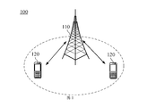
- FIG. 1 is a schematic diagram of a communication system architecture provided by an embodiment of the present application.
- Figure 2a is a schematic diagram of configuring PUCCU resources for subslots according to an embodiment of the present application
- FIG. 2b is a schematic diagram of configuring PUCCU resources for subslots according to another embodiment of the present application.
- FIG. 3 is a schematic flowchart of a wireless communication method provided by an embodiment of the present application.
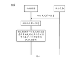
- FIG. 4 is a schematic flowchart of a wireless communication method provided by another embodiment of the present application.
- FIG. 5a is a schematic diagram of a PUCCH resource ID configured by a network device based on a first time slot according to an embodiment of the present application
- FIG. 5b is a schematic diagram of a terminal device according to an embodiment of the present application that determines a PUCCH resource that can be used by a sub-slot from the ID of the PUCCH resource configured by the network device based on the first time slot;
- FIG. 6 is a schematic structural diagram of a wireless communication device provided by an embodiment of the present application.
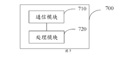
- FIG. 7 is a schematic structural diagram of a wireless communication device provided by another embodiment of the present application.
- FIG. 8 is a schematic structural diagram of a communication device provided by an embodiment of the present application.
- FIG. 9 is a schematic structural diagram of a chip provided by an embodiment of the present application.
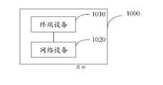
- FIG. 10 is a schematic structural diagram of a communication system provided by an embodiment of the present application.
- GSM Global System of Mobile Communication
- CDMA Code Division Multiple Access
- WCDMA Wideband Code Division Multiple Access
- GSM Global System of Mobile Communication
- GPRS General Packet Radio Service
- LTE Long Term Evolution
- FDD Frequency Division Duplex
- TDD Time Division Duplex
- UMTS Universal Mobile Telecommunication System
- WiMAX Worldwide Interoperability for Microwave Access
- the communication system 100 applied in the embodiment of the present application is shown in FIG. 1.
- the communication system 100 may include a network device 110, and the network device 110 may be a device that communicates with a terminal device 120 (or called a communication terminal or terminal).
- the network device 110 may provide communication coverage for a specific geographic area, and may communicate with terminal devices located in the coverage area.
- the network device 110 may be a base station (Base Transceiver Station, BTS) in a GSM system or a CDMA system, a base station (NodeB, NB) in a WCDMA system, or an evolved base station in an LTE system (Evolutional Node B, eNB or eNodeB), or the wireless controller in the Cloud Radio Access Network (CRAN), or the network equipment can be a mobile switching center, a relay station, an access point, a vehicle-mounted device, Wearable devices, hubs, switches, bridges, routers, network-side devices in 5G networks, or network devices in the future evolution of the Public Land Mobile Network (PLMN), etc.
- BTS Base Transceiver Station
- NodeB, NB base station
- LTE Long Term Evolutional Node B
- eNB evolved base station
- CRAN Cloud Radio Access Network
- the network equipment can be a mobile switching center, a relay station, an access point, a vehicle-mounted device, Wearable devices, hubs, switches
- the communication system 100 also includes at least one terminal device 120 located within the coverage area of the network device 110.
- the "terminal equipment” used here includes but is not limited to connection via wired lines, such as via Public Switched Telephone Networks (PSTN), Digital Subscriber Line (DSL), digital cable, and direct cable connection ; And/or another data connection/network; and/or via a wireless interface, such as for cellular networks, wireless local area networks (WLAN), digital TV networks such as DVB-H networks, satellite networks, AM- FM broadcast transmitter; and/or another terminal device that is set to receive/send communication signals; and/or Internet of Things (IoT) equipment.
- PSTN Public Switched Telephone Networks
- DSL Digital Subscriber Line
- WLAN wireless local area networks
- IoT Internet of Things
- a terminal device set to communicate through a wireless interface may be referred to as a "wireless communication terminal", a “wireless terminal” or a “mobile terminal”.
- mobile terminals include, but are not limited to, satellite or cellular phones; Personal Communications System (PCS) terminals that can combine cellular radio phones with data processing, fax, and data communication capabilities; can include radio phones, pagers, Internet/intranet PDA with internet access, web browser, memo pad, calendar, and/or Global Positioning System (GPS) receiver; and conventional laptop and/or palmtop receivers or others including radio telephone transceivers Electronic device.
- PCS Personal Communications System
- GPS Global Positioning System
- Terminal equipment can refer to access terminals, user equipment (UE), user units, user stations, mobile stations, mobile stations, remote stations, remote terminals, mobile equipment, user terminals, terminals, wireless communication equipment, user agents, or User device.
- the access terminal can be a cellular phone, a cordless phone, a Session Initiation Protocol (SIP) phone, a wireless local loop (Wireless Local Loop, WLL) station, a personal digital processing (Personal Digital Assistant, PDA), with wireless communication Functional handheld devices, computing devices or other processing devices connected to wireless modems, in-vehicle devices, wearable devices, terminal devices in 5G networks, or terminal devices in the future evolution of PLMN, etc.
- SIP Session Initiation Protocol
- WLL Wireless Local Loop
- PDA Personal Digital Assistant
- direct terminal connection (Device to Device, D2D) communication may be performed between the terminal devices 120.
- the 5G system or 5G network may also be referred to as a New Radio (NR) system or NR network.
- NR New Radio
- Figure 1 exemplarily shows one network device and two terminal devices.
- the communication system 100 may include multiple network devices and the coverage of each network device may include other numbers of terminal devices. The embodiment does not limit this.
- the communication system 100 may also include other network entities such as a network controller and a mobility management entity, which are not limited in the embodiment of the present application.
- network entities such as a network controller and a mobility management entity, which are not limited in the embodiment of the present application.
- the devices with communication functions in the network/system in the embodiments of the present application may be referred to as communication devices.
- the communication device may include a network device 110 having a communication function and a terminal device 120.
- the network device 110 and the terminal device 120 may be the specific devices described above, which will not be repeated here.
- the communication device may also include other devices in the communication system 100, such as network controllers, mobility management entities, and other network entities, which are not limited in the embodiment of the present application.
- one or more PUCCH resources can be supported in a time slot.
- the base station configures PUCCH resources, it can be configured according to the PUCCH resource set (PUCCH-Resource Set) or according to the PUCCH resource (PUCCH-Resource) configuration .
- PUCCH resource set a corresponding PUCCH resource set ID and at least one PUCCH resource can be configured; for each PUCCH resource, a corresponding PUCCH resource ID and specific PUCCH resource can be configured.
- the specific PUCCH resource can be configured according to the PUCCH format (format).
- the PUCCH format format
- the length of the PUCCH resource can be indicated, and the offset of the PUCCH resource relative to the reference point (offset) (that is, the Starting Symbol Index) )).
- offset that is, the Starting Symbol Index
- the difference between different PUCCH formats is: different lengths and/or different sizes of information carried.
- the boundary that is, the left boundary and/or the lower boundary
- Each PUCCH resource configured by the base station can be located in any slot and cannot exceed the boundary of the slot.
- a slot can be divided into multiple sub-slots.
- a slot can support 2 or 7 sub-slots, and the corresponding duration of each sub-slot can be 7 symbols (symbol) or 2 symbols (in Normal Cyclic (Normal Cyclic Prefix, NCP)) prefix).
- NCP Normal Cyclic Prefix
- the corresponding PUCCH resource can be configured for each sub-slot ID, and the PUCCH resource configuration in each sub-slot can be different.
- PUCCH1 resource and PUCCH2 resource can be configured in sub-slot1;
- PUCCH3 resource and PUCCH4 resource can be configured in sub-slot2.
- each PUCCH resource configured cannot exceed the slot boundary where the sub-slot is located.
- PUCCH resources can be uniformly configured for each sub-slot ID, that is, the PUCCH resource configuration in each sub-slot is the same.
- the PUCCH1 resource and the PUCCH2 resource can be configured uniformly in both sub-slot1 and sub-slot2.
- each PUCCH resource configured cannot exceed the slot boundary where the sub-slot is located.
- the two methods shown in FIG. 2a and FIG. 2b can determine the PUCCH resource of each sub-slot.
- the method of configuring PUCCH resources based on the sub-slot ID as the boundary shown in Figure 2a since the PUCCH resources of each sub-slot ID are configured independently, it will cause a large amount of RRC signaling overhead; for the method shown in Figure 2b
- the shown method of configuring PUCCH resources for the boundary based on the sub-slot ID can save RRC signaling overhead, but because the PUCCH resources of each sub-slot ID are uniformly configured, the flexibility of the configured PUCCH resources is low. .
- the embodiments of the present application provide the following solutions, which can avoid a large amount of RRC signaling overhead and at the same time ensure the flexibility of PUCCH resource configuration.
- FIG. 3 it is a schematic diagram of a wireless communication method 300 provided by an embodiment of this application.
- the network device sends first information to the terminal device, where the first information is used to indicate the PUCCH resource configured on the first time slot, the first time slot includes multiple sub-time slots, and the first information includes the The starting offset of the PUCCH resource relative to the boundary of the sub-slot.
- the PUCCH resource in the embodiment of this application may include one PUCCH resource or multiple PUCCH resources, which is not specifically limited in this application.
- the start offset of the PUCCH resource relative to the sub-slot boundary included in the first information may refer to .
- the starting offset of the PUCCH resource relative to the boundary of sub-slot1 can also refer to the starting offset of the PUCCH resource relative to the boundary of sub-slot2, or the starting offset of the PUCCH resource relative to sub-slot1 and sub-slot2 The starting offset of the boundary.
- the PUCCH resource in the embodiment of the present application includes multiple PUCCH resources, the PUCCH resource may also be referred to as a PUCCH resource set.
- the network device may first determine the first information before sending the first information to the terminal device, that is, configure the PUCCH resource based on the first time slot. After the network device configures the PUCCH resource based on the first time slot, the first information may be sent to the terminal device. After receiving the first information, the terminal device may determine the PUCCH resource that can be used by at least one sub-slot of the multiple sub-slots based on the multiple sub-slots included in the first time slot.
- the terminal device can determine the appropriateness of at least one sub-slot based on the starting offset relative to the sub-slot boundary. PUCCH resources, which can ensure the flexibility of PUCCH resource configuration.
- FIG. 4 it is a schematic diagram of a wireless communication method 400 provided by another embodiment of this application.
- the network device sends first information to the terminal device, where the first information is used to indicate a PUCCH resource configured on a first time slot, the first time slot includes a plurality of sub-time slots, and the first information includes the The starting offset of the PUCCH resource relative to the boundary of the sub-slot.
- the terminal device receives the first information sent by the network device.
- the terminal device determines a PUCCH resource of at least one sub-slot of the multiple sub-slots from the PUCCH resource according to the first information.
- the terminal device may determine the PUCCH resource of at least one sub-slot from the PUCCH resource according to the first information.
- the terminal device can be based on the starting offset of the PUCCH resource on sub-slot1 and/or sub-slot2 relative to the boundary of sub-slot1 and/or sub-slot2 Determine the PUCCH resources that can be used on sub-slot1 and/or sub-slot2.
- the starting offset relative to the boundary of sub-slot1 and/or sub-slot2 may be a value, or a starting offset may be separately configured for at least one sub-slot.
- the start offset of the PUCCH resource on the at least one sub-slot is less than or equal to the configuration value of one sub-slot; or, the PUCCH on the at least one sub-slot
- the start offset of the resource is limited by the configuration value of a sub-slot.
- the first time slot may include multiple sub-slots, and the start offset of the PUCCH resource on at least one of the multiple sub-slots may be less than or equal to the configuration value of one sub-slot Or, the start offset of the PUCCH resource on at least one sub-slot of the multiple sub-slots is limited by the configuration value of one sub-slot.
- the configuration value of the sub-slot in the embodiment of the present application can be understood as the length of the sub-slot.
- the start offset of PUCCH resources on at least one sub-slot is limited by the length of one sub-slot.
- the starting offset of PUCCH resources on at least one sub-slot is limited to the length of one sub-slot. It can be understood that the starting offset of PUCCH resources on at least one sub-slot is less than or Equal to the length of one sub-slot.
- the configuration value of the sub-slot in the embodiment of the present application can also be understood as including the start position and/or the end position of the sub-slot. That is, the start offset of the PUCCH resource on at least one sub-slot is limited by the start position and/or the end position of one sub-slot.
- the first time slot includes two sub-slots, sub-slot1 and sub-slot2, and the length of each sub-slot is 7 symbols, then these two sub-slots
- the start offset on at least one of the sub-slots is less than or equal to 7 symbols; or, the start offset on at least one of the two sub-slots is limited to 7 symbols.
- the starting offset of sub-slot1 in the embodiment of the present application may be less than or equal to 7 symbols; or, the starting offset of sub-slot2 may be less than or equal to 7 symbols; or, sub- The start offset of slot1 and sub-slot2 can both be less than or equal to 7 symbols.
- the start offset of the PUCCH resource on the at least one sub-slot is less than or equal to a first threshold, and the first threshold is less than or equal to a configuration value of one sub-slot.
- the first time slot includes two sub-slots, sub-slot1 and sub-slot2, and each sub-slot has a length of 7 symbols.
- the first threshold is 3
- the start offset on at least one of the two sub-slots is less than or equal to 3 symbols.
- the starting offset of sub-slot1 in the embodiment of the present application may be less than or equal to 3 symbols; or, the starting offset of sub-slot2 may be less than or equal to 3 symbols; or, sub- The start offset of slot1 and sub-slot2 can both be less than or equal to 3 symbols.
- the numerical values listed for the first threshold in the embodiments of the present application are only examples, and may also be other numerical values, for example, 4, 5, or 6, etc., which are not specifically limited in the present application. It should be noted that the first threshold is less than or equal to the configuration of a sub-slot, that is, if the length of a sub-slot is 7 symbols, the first threshold can be set to 3, 4, 5, or 6, as long as The length of no more than one sub-time slot can be applied to the embodiments of the present application.
- the first information further includes at least one of the following information: information of the at least one sub-slot, the length of the PUCCH resource, and the start symbol of the PUCCH resource Offset or index, configuration of the first time slot, restriction information.
- the information of the at least one sub-slot includes at least one of the following information: an index of the at least one sub-slot, and a boundary position of the at least one sub-slot.
- the boundary position of the at least one sub-slot includes a lower boundary position and/or a starting boundary position of the at least one sub-slot.
- the first information may also include sub-slot1 and/or sub-slot2 related information, for example, The index of sub-slot1 and/or sub-slot2, and the boundary position of sub-slot1 and/or sub-slot2.
- the boundary position of sub-slot1 and/or sub-slot2 in the embodiment of the present application may include the lower boundary position and/or the starting boundary position of sub-slot1 and/or sub-slot2.
- the lower boundary position of sub-slot1 included in the first information may refer to the smallest position in the frequency domain of sub-slot1; the start of sub-slot1 included in the first information
- the starting boundary position may refer to the smallest position in the time domain of sub-slot1.
- the start symbol offset or index of the PUCCH resource in the embodiment of the present application may refer to the start offset or index of the PUCCH resource relative to the sub-slot. For example, assuming that the first slot includes two sub-slots, sub-slot1 and sub-slot2, if the start offset of PUCCH resource 1 included in sub-slot1 relative to sub-slot1 is 2, then PUCCH The start symbol index of resource 1 may be 2, so that the terminal device can know the location of PUCCH resource 1 through the start symbol index. Or, according to the start symbol index 2 of PUCCH resource 1, the terminal device can know the position of PUCCH resource 1 through the start symbol index, for example, the PUCCH resource position starts from the second symbol or the symbol with the symbol index of 2.
- the start offset of the PUCCH resource relative to the sub-slot in the embodiment of the application can have a one-to-one correspondence with the index.
- the terminal device can know the index of the PUCCH resource after receiving the PUCCH resource index.
- the location of the PUCCH resource For example, if the start offset of PUCCH resource 1 included in sub-slot1 relative to sub-slot1 is 2, then the start symbol index of PUCCH resource 1 can also be 1, or other values. This application does not make this Specific restrictions.
- the restriction information in the embodiment of this application may mean that the selected PUCCH resource cannot exceed the boundary of the first time slot, that is, when the PUCCH resource of sub-slot 1 and/or sub-slot 2 is selected, the selected PUCCH resource expires The position or upper boundary cannot exceed the boundary of the first time slot.
- the length of the PUCCH resource on the at least one sub-slot is less than or equal to the configuration value of the first time slot; or, the start position and the end position of the PUCCH resource are located at In the first time slot.
- the configuration value of the first time slot here can be understood as the length of the first time slot.
- the length of the first time slot is 14, the first time slot includes two sub-slots, sub-slot1 and sub-slot2, and the length of each sub-slot is 7 symbols. Then the length of the PUCCH resource on sub-slot1 and/or sub-slot2 is less than or equal to 14 symbols, or the start position and end position of the PUCCH resource on sub-slot1 and/or sub-slot2 are located in the first The time slot includes 14 symbols.
- the PUCCH resource on the at least one subslot includes the PUCCH time domain resource on the at least one subslot and/or the PUCCH frequency domain on the at least one subslot Resources.
- the length of the first time slot is 14, and the first time slot includes two sub-slots, namely sub-slot1 and sub-slot2.
- the PUCCH resources on sub-slot1 and/or sub-slot2 may include time domain resources and/or frequency domain resources.
- the method further includes: the terminal device uses the determined PUCCH resource of the at least one sub-slot to send uplink control information (Uplink Control Information, UCI) to the network device.
- uplink control information Uplink Control Information, UCI
- the terminal device may determine the PUCCH resource of at least one sub-slot from the PUCCH resource according to the first information. After determining the PUCCH resource of the at least one sub-slot, the terminal device may send UCI to the network device according to the determined PUCCH resource in the at least one sub-slot.
- the UCI sent by the terminal device to the network device may include Hybrid Automatic Repeat reQuest-Acknowledgement/Not-acknowledgement, HARQ-ACK/NACK, and channel state information (Channel State Information, CSI) and Scheduling Request (SR), etc.
- Hybrid Automatic Repeat reQuest-Acknowledgement/Not-acknowledgement HARQ-ACK/NACK
- channel state information Channel State Information, CSI
- SR Scheduling Request
- HARQ-ACK/NACK can perform HARQ confirmation on downlink data sent on a physical downlink shared channel (Physical Downlink Shared Channel, PDSCH);
- CSI can include channel quality indicators (Channel Quality Indicator, CQI), precoding matrix indicators ( Information such as Precoding Matrix Indicator (PMI) and Rank Indication (Rank Indication, RI) is used for the downlink channel quality of high-speed network equipment, so that the network equipment can perform downlink scheduling reasonably;
- SR can be used to request the network equipment for the uplink shared channel ( Uplink-Shared Channel, UL-SCH) resources.
- the method further includes: the terminal device uses the determined PUCCH resource of the at least one sub-slot to send UCI to the network device, including: the terminal device determines the A first target PUCCH resource on at least one sub-slot; the terminal device uses the first target PUCCH resource to transmit the UCI to the network device on the at least one sub-slot.
- the terminal device may determine the first target PUCCH resource on at least one sub-slot, so that the terminal device can use the first PUCCH resource.
- the target PUCCH resource transmits UCI to the network device.
- the first target PUCCH resource in the embodiment of this application may include one PUCCH resource or multiple PUCCH resources, which is not specifically limited in this application.
- the terminal device can use this PUCCH resource or the first target PUCCH resource to transmit UCI to the network device; in a sub-slot
- the terminal device may select one PUCCH resource from the multiple PUCCH resources to transmit UCI to the network device.
- the terminal device can determine the first target PUCCH resource on at least one sub-slot.
- the following will specifically introduce how the terminal device determines the PUCCH resource on at least one sub-slot The target PUCCH resource.
- determining the first target PUCCH resource on the at least one sub-slot by the terminal device includes: the terminal device receives the downlink control information sent by the network device (Downlink Control Information). , DCI) and/or RRC signaling, the DCI and/or the RRC signaling carries second information; the terminal device determines the at least one sub-slot according to the DCI and/or the RRC signaling The first target PUCCH resource above.
- the terminal device determines the first target PUCCH resource on the at least one sub-slot according to the second information in the DCI and/or the RRC signaling.
- the terminal device may also be uncertain of the first target PUCCH resource, and may transmit UCI on the PUCCH resource indicated by the PUCCH resource indicated by the DCI and/or RRC signaling sent by the network device.
- the second information includes at least one of the following information: the position of the sub-slot for transmitting the UCI, the identifier of the sub-slot for transmitting the UCI, and the UCI for transmitting
- the sub-slot of the UCI is relative to the offset of the frame or time slot or sub-slot in which the DCI and/or RRC signaling is located, and the sub-slot of the UCI is transmitted relative to the physical downlink shared channel PDSCH indicated by the DCI
- the offset of the frame or time slot or sub time slot corresponding to the transmission, PUCCH resource set ID, and the PUCCH resource ID.
- the terminal device can determine The first target PUCCH resource may be determined in the above-mentioned manner.
- the terminal device can follow The position of the sub-slot for transmitting UCI included in the second information determines which sub-slot PUCCH resource is used for transmission. Specifically, it can be determined that the first target PUCCH resource on sub-slot1 and/or sub-slot2 is used for transmission.
- the position of the sub-slot for transmitting UCI is taken as an example for description.
- the terminal device may determine which PUCCH resource of which sub-slot is used for transmission according to the position of the sub-slot for transmitting UCI and the resource ID included in the second information. Specifically, it can be determined that the specific PUCCH resource on sub-slot1 or sub-slot2 is used for transmission.
- the terminal device may determine the first target PUCCH resource from sub-slot1. Assuming that sub-slot1 includes PUCCH resource 1, the terminal device can determine PUCCH resource 1 as the first target PUCCH resource, so that PUCCH resource 1 can be used to send UCI to the network device on sub-slot1; suppose sub-slot1 includes PUCCH Resource 1 and PUCCH resource 2, then the terminal device can select one PUCCH resource from PUCCH resource 1 and PUCCH resource 2 as the first target PUCCH resource for UCI transmission.
- the terminal device may also determine the first sub-slot on the at least one sub-slot based on the offset of the sub-slot for transmitting UCI carried in the second information relative to the frame or slot or sub-slot where the DCI and/or RRC signaling is located.
- Target PUCCH resource Assuming that the time slot where DCI and/or RRC signaling is located is time slot 1 or sub-slot 1 of time slot 1, the terminal device receives the sub-slot for transmitting UCI relative to the frame or time where DCI and/or RRC signaling is located.
- the first target PUCCH resource can be determined according to the offset and the time slot in which the DCI and/or RRC signaling is located.
- the terminal device can determine a time slot that is 2 time slots away from time slot 1 or sub-slot 1 of this time slot is the time slot where the first target PUCCH resource is located, so that the first target PUCCH resource can be determined.
- Target PUCCH resource If the offset is 2, the terminal device can determine a time slot that is 2 time slots away from time slot 1 or sub-slot 1 of this time slot is the time slot where the first target PUCCH resource is located, so that the first target PUCCH resource can be determined.
- Target PUCCH resource Target PUCCH resource.
- the terminal device may also determine at least one PUCCH resource ID based on the offset of the sub-slot for transmitting UCI carried in the second information relative to the frame or slot or sub-slot where the DCI and/or RRC signaling is located.
- the first target PUCCH resource on the sub-slot Assuming that the time slot where DCI and/or RRC signaling is located is time slot 1 or sub-slot 1 of time slot 1, the terminal device receives the sub-slot for transmitting UCI relative to the frame or time where DCI and/or RRC signaling is located.
- the first target PUCCH resource can be determined according to the offset, the time slot where the DCI and/or RRC signaling is located, and the PUCCH resource ID1. If the offset is 2, the terminal device can determine a time slot that is 2 time slots away from the time slot 1 or the PUCCH resource ID1 of the PUCCH resource of sub-slot 1 of the time slot to transmit UCI.
- the terminal device may also determine the first target PUCCH resource on at least one sub-slot based on other information, for example, the identifier of the sub-slot for transmitting UCI, or the sub-slot for transmitting UCI corresponds to the PDSCH transmission indicated by the DCI
- the offset of the frame or slot or sub-slot, or PUCCH resource set ID, or PUCCH resource ID are at least determined by the offset of the frame or time slot or sub time slot where DCI and/or RRC signaling is based on the position of the UCI transmission sub-slot and the UCI transmission sub-slot as described above.
- the manner of the first target PUCCH resource of a sub-slot is basically similar, and for the sake of brevity, it will not be repeated here.
- the method further includes: the terminal device selects a second target PUCCH resource from the first target PUCCH resource;
- the terminal device using the first target PUCCH resource to transmit UCI to the network device on the at least one sub-slot includes: the terminal device uses the second target PUCCH resource in the at least one sub-slot The UCI is transmitted to the network device in the time slot.
- the terminal device selecting a second target PUCCH resource from the first target PUCCH resource includes: the terminal device selecting from the first target PUCCH resource according to a preset condition The second target PUCCH resource.
- the terminal device may determine one PUCCH resource from the first target PUCCH resource as The second target PUCCH resource can thereby transmit UCI to the network device in at least one sub-slot according to the second target PUCCH resource.
- the terminal device may also determine a PUCCH resource as the second target PUCCH resource from multiple PUCCH resources on at least one sub-slot that are determined to be usable, so that the second target PUCCH resource may be in the at least one sub-slot according to the second target PUCCH resource. Transmit UCI to network equipment.
- the terminal device determines that the available first target PUCCH resource on sub-slot1 includes PUCCH resource 1 and PUCCH resource 2, Then the terminal device can select a PUCCH resource from PUCCH resource 1 and PUCCH resource 2 as the second target PUCCH resource, so that the second target PUCCH resource can be used to transmit UCI to the network device on sub-slot1.
- the terminal device determines that the available PUCCH resources on sub-slot1 include PUCCH resource 1 and PUCCH resource 2, the terminal device One PUCCH resource can be selected from PUCCH resource 1 and PUCCH resource 2 as the second target PUCCH resource, so that the second target PUCCH resource can be used to transmit UCI to the network device on sub-slot1.
- the terminal device can select one PUCCH resource from the multiple PUCCH resources to transmit uplink control information to the network device.
- the following will specifically introduce the terminal device from multiple PUCCH resources. Select a PUCCH resource from the resources to transmit uplink control information to the network device.
- the preset condition includes at least one of the following conditions: any PUCCH resource in the first target PUCCH resource, and a PUCCH resource in the first target PUCCH resource in the time domain
- the PUCCH resource with the longest length, the PUCCH resource in the first target PUCCH resource with the shortest time domain length, and the upper boundary of the PUCCH resource in the first target PUCCH resource is closest to the at least one sub-time A PUCCH resource on the upper boundary of the slot
- the upper boundary of the PUCCH resource in the first target PUCCH resource is the one PUCCH resource whose upper boundary is the farthest from the upper boundary of the at least one sub-slot
- the PUCCH resource whose cut-off position of the PUCCH resource in the first target PUCCH resource is the latest, and the PUCCH resource in the first target PUCCH resource
- the terminal device Take the terminal device that can select the PUCCH resource with the longest time domain length among multiple PUCCH resources as an example. Assuming that the terminal device receives the DCI scheduled DL transmission sent by the network device, instructs the terminal device to use PUCCH resource 1 on sub-slot1 to transmit the corresponding HARQ-ACK, and the terminal device also triggers the SR, and the PUCCH corresponding to the SR
- the resource ID is 4, that is, the terminal device needs to use PUCCH resource 4 to transmit SR on sub-slot1 according to the indicated PUCCH resource ID4.
- the terminal device may select a PUCCH resource with a longer time domain length from PUCCH resource 1 and PUCCH resource 4 to transmit the corresponding HARQ-ACK and/or SR. If the PUCCH resource with a longer time domain length in PUCCH resource 1 and PUCCH resource 4 is PUCCH resource 1, the terminal device can use PUCCH resource 1 to transmit the corresponding HARQ-ACK and/or SR in sub-slot
- the terminal device can select the PUCCH resource with the latest cut-off position among multiple PUCCH resources as an example. Assume that the terminal device needs to use PUCCH resource 1 on sub-slot 1 to transmit the corresponding HARQ-ACK, and the terminal device also needs to use PUCCH resource 4 on sub-slot 1 to transmit SR. In this case, the terminal device may select the PUCCH resource with the latest cut-off position from PUCCH resource 1 and PUCCH resource 4 to transmit the corresponding HARQ-ACK and/or SR. If the PUCCH resource with the latest cut-off position in PUCCH resource 1 and PUCCH resource 4 is PUCCH resource 1, the terminal device can use PUCCH resource 1 to transmit the corresponding HARQ-ACK and/or SR in sub-slot 1.
- the terminal device can also select a PUCCH resource to transmit the corresponding HARQ-ACK and SR, HARQ-ACK and channel state information reference signal (Channel System Information-Reference Signal, CSI-RS), CSI-RS under other preset conditions.
- CSI-RS Channel System Information-Reference Signal
- RS and SR, etc. for the sake of brevity, they will not be repeated here.
- FIG. 5a it is a schematic diagram of the PUCCH resource ID configured by the network device for the first time slot provided by an embodiment of this application.
- the abscissa in the figure represents the time domain
- the ordinate represents the frequency domain.
- the PUCCH resource configured by the network device for the first time slot includes two PUCCH Resource sets, namely PUCCH Resource set1 and PUCCH Resource set2.
- PUCCH Resource set ID1 The identifier corresponding to PUCCH Resource set1 is PUCCH Resource set ID1, which includes 2 PUCCH resources, PUCCH resource 1 and PUCCH resource 2, respectively.
- the identifier corresponding to PUCCH resource 1 is PUCCH resource ID1
- the physical resource block (PRB) starting from PUCCH resource 1 is 0
- the supported format is format2, which occupies a total of 2 PRBs, which is offset from the sub-slot boundary.
- the shift amount is 3 symbols, that is, the index of the start symbol is 3, and the time domain length is 8 symbols.
- the identifier corresponding to PUCCH resource 2 is PUCCH resource ID2, the starting PRB of PUCCH resource 2 is 3, the supported format is format2, which occupies a total of 2 PRBs, and the offset relative to the sub-slot boundary is 3 symbols, that is, the start symbol The index is 3, and the time domain length is 2 symbols.
- PUCCH Resource set ID2 The identifier corresponding to PUCCH Resource set2 is PUCCH Resource set ID2, which includes 3 PUCCH resources, namely PUCCH resource 3, PUCCH resource 4, and PUCCH resource 5.
- the identifier corresponding to PUCCH resource 3 is PUCCH resource ID3, the starting PRB of PUCCH resource 3 is 0, the supported format is format2, which occupies a total of 1 PRB, and the offset relative to the sub-slot boundary is 1 symbol, that is, the start symbol The index of is 1, and the time domain length is 3 symbols.
- the identifier corresponding to PUCCH resource 4 is PUCCH resource ID4, the starting PRB of PUCCH resource 4 is 7, the supported format is format2, which occupies a total of 2PRB, and the offset relative to the sub-slot boundary is 4 symbols, that is, the index of the starting symbol is 4.
- the time domain length is 6 symbols.
- the identifier corresponding to PUCCH resource 5 is PUCCH resource ID5, the starting PRB of PUCCH resource 5 is 5, the supported format is format2, which occupies a total of 1 PRB, and the offset relative to the sub-slot boundary is 2 symbols, that is, the index of the starting symbol is 2.
- the time domain length is 2 symbols.
- the above describes the PUCCH resource configured by the network device for the first time slot.
- the network device configures the PUCCH resource, it sends the configured PUCCH resource and related information to the terminal device so that the terminal device can determine at least one of the first time slots PUCCH resources that can be used by the sub-slot.
- the following will specifically introduce the PUCCH resources that the terminal device can use to determine at least one sub-slot in the first time slot.
- FIG. 5b a schematic diagram of the PUCCH resources that can be used by the terminal device selected from the PUCCH resources configured by the network device based on the first time slot according to an embodiment of this application.
- the terminal device may determine it according to the information included in the first information.
- the first information may include: information of at least one sub-slot, such as the sub-slot ID and/or the boundary position of the sub-slot (the following boundary position and/or starting position); the length of the PUCCH resource; the start of the PUCCH resource Start symbol offset and index; configuration of the first time slot; restriction information, for example, the start position and end position of the selected PUCCH resource are located in the first time slot.
- the identifier PUCCH ID1 corresponding to PUCCH resource 1 is taken as an example for description.
- the offset of PUCCH ID1 relative to the boundary of sub-slot1 is 3 symbols, and the length of PUCCH resource 1 is less than the length of the first time slot, and the starting PRB of PUCCH resource 1 is 0, which occupies 2 in total.
- PRB which starts from the position of 0 in the frequency domain and ends at the position of 2 in the frequency domain. Therefore, PUCCH resource 1 can be used as the usable PUCCH resource of sub-slot 1.
- PUCCH resource 2 PUCCH resource 3, PUCCH resource 4, and PUCCH resource 5 can all be used as PUCCH resources of sub-slot1.
- the identifiers corresponding to PUCCH resource 2, PUCCH resource 3, PUCCH resource 4, and PUCCH resource 5 in the embodiment of the present application may be PUCCH ID2, PUCCH ID3, PUCCH ID4, and PUCCH ID5 shown in FIG. 5a and FIG. 5b, respectively.
- PUCCH resource 3 and PUCCH resource 2 are located in sub-slot 2, and the lengths of PUCCH resource 3 and PUCCH resource 2 are 3 symbols and 2 symbols respectively, which do not exceed the slot boundary.
- PUCCH resource 3 starts with a PRB of 0, occupying a total of 1 PRB, that is, starting from the position of frequency domain 0 and ending at the position of frequency domain 1;
- PUCCH resource 2 starts with a PRB of 3, occupying a total of 2 PRB, that is, it starts at the position of 3 in the frequency domain and ends at the position of 5 in the frequency domain. Therefore, PUCCH resource 3 and PUCCH resource 2 can be used as PUCCH resources of sub-slot2.
- the usable PUCCH resources of sub-slot 1 determined by the terminal device include: PUCCH resource 1, PUCCH resource 2, PUCCH resource 3, PUCCH resource 4, and PUCCH resource 5;
- the usable PUCCH of sub-slot 2 determined by the terminal device Resources include: PUCCH resource 2 and PUCCH resource 3.
- the terminal device determines the usable PUCCH resources of sub-slot1 and sub-slot2
- the terminal device receives the DCI and/or RRC signaling sent by the network device, it is based on the information contained in the DCI and/or RRC signaling.
- the included position and/or offset determine the first target PUCCH resource of sub-slot1 and/or sub-slot2 or the PUCCH resource used (such as the PUCCH resource with the designated identifier).
- the terminal device can follow The second information includes the location of the UCI transmission sub-slot to determine the sub-slot information where the PUCCH resource used is located, or to determine the first target PUCCH resource on sub-slot1 and/or sub-slot2.
- the terminal device may determine the first target PUCCH resource from sub-slot1. Assuming that sub-slot1 includes PUCCH resource 1, the terminal device can determine PUCCH resource 1 as the first target PUCCH resource, so that PUCCH resource 1 can be used to send UCI to the network device on sub-slot1. Assuming that the PUCCH resource ID indicated by RRC or /DCI is PUCCH resource ID 1, that is, PUCCH resource 1, the terminal device can use PUCCH resource 1 to send UCI to the network device on sub-slot1.
- the terminal device receives the DCI of the network device, and the DCI indicates that the corresponding PUCCH resource ID for transmitting HARQ-ACK is 1.
- the terminal device can use PUCCH resource 1 on sub-slot 1 according to the indicated PUCCH resource ID 1 Transmit the corresponding HARQ-ACK.
- the terminal device triggers the SR transmission, and the PUCCH resource ID corresponding to the SR is 4, that is, the terminal device needs to use the PUCCH resource 4 to transmit the SR on the sub-slot1 according to the indicated PUCCH resource ID4.
- the terminal device needs to select one PUCCH resource from multiple PUCCH resources to transmit the corresponding HARQ-ACK and SR.
- the terminal device selects a PUCCH resource from multiple PUCCH resources to transmit the corresponding HARQ-ACK and SR, it can be selected based on different preset conditions, for example, it can select one PUCCH resource arbitrarily from multiple PUCCH resources ; Alternatively, the PUCCH resource with the longest time domain length among multiple PUCCH resources can be selected; or, the PUCCH resource with the shortest time domain length among multiple PUCCH resources can be selected; or, the upper boundary of the multiple PUCCH resources can be selected The PUCCH resource closest to the upper boundary of the sub-slot; alternatively, the PUCCH resource whose lower boundary among the multiple PUCCH resources is closest to the lower boundary of the sub-slot can be selected; alternatively, the PUCCH with the latest cut-off position among multiple PUCCH resources can be selected Resource; or, the PUCCH resource with the earliest starting position among multiple PUCCH resources can be selected; or the PUCCH resource corresponding to the UCI with the highest priority; or the PUCCH resource
- the terminal device Take the terminal device that can select the PUCCH resource with the longest time domain length among multiple PUCCH resources as an example. Assume that the terminal device receives the DCI sent by the network device, indicating that the terminal device needs to use PUCCH resource 1 on sub-slot1 to transmit the corresponding HARQ-ACK, and the terminal device also triggers the SR, and the PUCCH resource ID corresponding to the SR is 4. That is, the terminal device needs to use PUCCH resource 4 to transmit SR on sub-slot1 according to the indicated PUCCH resource ID4. In this case, the terminal device may select a PUCCH resource with a longer time domain length from PUCCH resource 1 and PUCCH resource 4 to transmit the corresponding HARQ-ACK and/or SR.
- the PUCCH resource with longer time domain length in PUCCH resource 1 and PUCCH resource 4 is PUCCH resource 1, and the terminal device can use PUCCH resource 1 to transmit the corresponding HARQ in sub-slot 1. -ACK and/or SR.
- the terminal device can select the PUCCH resource with the latest cut-off position among multiple PUCCH resources as an example. Assume that the terminal device needs to use PUCCH resource 1 on sub-slot 1 to transmit the corresponding HARQ-ACK, and the terminal device also needs to use PUCCH resource 4 on sub-slot 1 to transmit SR. In this case, the terminal device may select the PUCCH resource with the latest cut-off position from PUCCH resource 1 and PUCCH resource 4 to transmit the corresponding HARQ-ACK and/or SR.
- the latest PUCCH resource in the cut-off position of PUCCH resource 1 and PUCCH resource 4 is PUCCH resource 1, and the terminal device can use PUCCH resource 1 to transmit the corresponding HARQ- in sub-slot 1.
- ACK and/or SR are PUCCH resource 1 to transmit the corresponding HARQ- in sub-slot 1.
- the terminal device can also select a PUCCH resource to transmit the corresponding HARQ-ACK and SR, HARQ-ACK and CSI-RS, CSI-RS and SR under other preset conditions. For the sake of brevity, it will not be repeated here.
- FIG. 6 is a wireless communication device 600 provided by an embodiment of the present application.
- the wireless communication device 600 may include a communication module 610.
- the communication module 610 is configured to send first information to a terminal device, where the first information is used to indicate a physical uplink control channel PUCCH resource configured on a first time slot, the first time slot includes a plurality of sub-time slots, and the The first information includes the start offset of the PUCCH resource with respect to the boundary of the sub-slot.
- the start offset of the PUCCH resource on at least one sub-slot of the plurality of sub-slots is less than or equal to a configuration value of one sub-slot.
- the start offset of the PUCCH resource on at least one sub-slot of the plurality of sub-slots is less than or equal to a first threshold, and the first threshold is less than or equal to one sub-slot.
- the configuration value of the time slot is less than or equal to a first threshold, and the first threshold is less than or equal to one sub-slot.
- the first information further includes at least one of the following information: information of at least one sub-slot of the plurality of sub-slots, the length of the PUCCH resource, and the The start symbol offset or index of the PUCCH resource, the configuration of the first time slot, and restriction information.
- the information of the at least one sub-slot includes at least one of the following information: an index of the at least one sub-slot, and a boundary position of the at least one sub-slot.
- the boundary position of the at least one sub-slot includes a lower boundary position and/or a starting boundary position of the at least one sub-slot.
- the length of the PUCCH resource on at least one sub-slot of the plurality of sub-slots is less than or equal to the configuration of the first time slot; or, the start of the PUCCH resource The position and the end position are within the first time slot.
- the PUCCH resource on at least one sub-slot of the plurality of sub-slots includes the PUCCH time domain resource on the at least one sub-slot and/or the at least one sub-slot PUCCH frequency domain resources on the slot.
- FIG. 7 is a wireless communication device 700 provided by an embodiment of the present application.
- the wireless communication device 700 may include a communication module 710 and a processing module 720.
- the communication module 710 is configured to receive first information sent by a network device, where the first information is used to indicate a physical uplink control channel PUCCH resource configured on a first time slot, and the first time slot includes multiple sub-time slots, so The first information includes the start offset of the PUCCH resource with respect to the boundary of the sub-slot.
- the processing module 720 is configured to determine a PUCCH resource of at least one sub-slot of the plurality of sub-slots from the PUCCH resource according to the first information.
- the start offset of the PUCCH resource on the at least one sub-slot is less than or equal to a configuration value of one sub-slot.
- the start offset of the PUCCH resource on the at least one sub-slot is less than or equal to a first threshold, and the first threshold is less than or equal to a configuration value of one sub-slot.
- the first information further includes at least one of the following information: information of the at least one sub-slot, the length of the PUCCH resource, and the start symbol of the PUCCH resource Offset and index, configuration of the first time slot, restriction information.
- the information of the at least one sub-slot includes at least one of the following information: an index of the at least one sub-slot, and a boundary position of the at least one sub-slot.
- the boundary position of the at least one sub-slot includes a lower boundary position and/or a starting boundary position of the at least one sub-slot.
- the length of the PUCCH resource on the at least one sub-slot is less than or equal to the configuration of the first time slot; or, the start position and the end position of the PUCCH resource are located at Said in the first time slot.
- the PUCCH resource on the at least one subslot includes the PUCCH time domain resource on the at least one subslot and/or the PUCCH frequency domain on the at least one subslot Resources.
- the communication module 710 is further configured to use the determined PUCCH resource of the at least one sub-slot to send uplink control information UCI to the network device.
- the processing module 720 is further configured to: determine the first target PUCCH resource on the at least one sub-slot; the communication module 710 is further configured to: use the first target The PUCCH resource transmits UCI to the network device on the at least one sub-slot.
- the communication module 710 is further configured to: receive downlink control information DCI and/or radio resource control RRC signaling sent by the network device, the DCI and/or the RRC signaling The command carries second information; the processing module 720 is further configured to determine the first target PUCCH resource on the at least one sub-slot according to the DCI and/or the RRC signaling.
- the second information includes at least one of the following information: the position of the sub-slot for transmitting the UCI, the identifier of the sub-slot for transmitting the UCI, and the UCI for transmitting
- the sub-slot of the UCI is relative to the offset of the frame or time slot or sub-slot in which the DCI and/or RRC signaling is located, and the sub-slot of the UCI is transmitted relative to the physical downlink shared channel PDSCH indicated by the DCI
- the offset of the frame or slot or sub-slot corresponding to the transmission; the PUCCH resource set identification ID; the PUCCH resource ID.
- the processing module 720 is further configured to: select a second target PUCCH resource from the first target PUCCH resource;
- the communication module 710 is further configured to: use the second target PUCCH resource to transmit the UCI to the network device on the at least one sub-slot.
- the processing module 720 is further configured to select a second target PUCCH resource from the first target PUCCH resource according to a preset condition.
- the preset condition includes at least one of the following conditions: any PUCCH resource in the first target PUCCH resource, and a PUCCH resource in the first target PUCCH resource in the time domain
- the PUCCH resource with the longest length, the PUCCH resource in the first target PUCCH resource with the shortest time domain length, and the upper boundary of the PUCCH resource in the first target PUCCH resource is closest to the at least one sub-time A PUCCH resource on the upper boundary of the slot
- the upper boundary of the PUCCH resource in the first target PUCCH resource is the one PUCCH resource whose upper boundary is the farthest from the upper boundary of the at least one sub-slot
- the PUCCH resource whose cut-off position of the PUCCH resource in the first target PUCCH resource is the latest, and the PUCCH resource in the first target PUCCH resource
- the embodiment of the present application also provides a communication device 800, as shown in FIG. 8, including a processor 810 and a memory 820, the memory is used to store a computer program, the processor is used to call and run the computer stored in the memory Program to execute the method in the embodiment of this application.
- the processor 810 may call and run a computer program from the memory 820 to implement the method in the embodiment of the present application.
- the memory 820 may be a separate device independent of the processor 810, or may be integrated in the processor 810.
- the communication device 800 may further include a transceiver 830, and the processor 810 may control the transceiver 830 to communicate with other devices. Specifically, it may send information or data to other devices, or receive other devices. Information or data sent by the device.
- the transceiver 830 may include a transmitter and a receiver.
- the transceiver 830 may further include an antenna, and the number of antennas may be one or more.
- the communication device 800 may specifically be a network device in an embodiment of the present application, and the communication device 800 may implement the corresponding process implemented by the network device in each method of the embodiment of the present application. For the sake of brevity, it will not be repeated here. .
- the communication device 800 may specifically be a mobile terminal/terminal device of an embodiment of the application, and the communication device 800 may implement the corresponding processes implemented by the mobile terminal/terminal device in each method of the embodiment of the application.
- the communication device 800 may implement the corresponding processes implemented by the mobile terminal/terminal device in each method of the embodiment of the application.
- I will not repeat it here.
- FIG. 9 is a schematic structural diagram of a chip of an embodiment of the present application.
- the chip 900 shown in FIG. 9 includes a processor 910, and the processor 910 can call and run a computer program from the memory to implement the method in the embodiment of the present application.
- the chip 900 may further include a memory 920.
- the processor 910 can call and run a computer program from the memory 920 to implement the method in the embodiment of the present application.
- the memory 920 may be a separate device independent of the processor 910, or may be integrated in the processor 910.
- the chip 900 may further include an input interface 930.
- the processor 910 can control the input interface 930 to communicate with other devices or chips, and specifically, can obtain information or data sent by other devices or chips.
- the chip 900 may further include an output interface 940.
- the processor 910 can control the output interface 940 to communicate with other devices or chips, and specifically, can output information or data to other devices or chips.
- the chip can be applied to the network device in the embodiment of the present application, and the chip can implement the corresponding process implemented by the network device in each method of the embodiment of the present application.
- the chip can implement the corresponding process implemented by the network device in each method of the embodiment of the present application.
- the chip can be applied to the mobile terminal/terminal device in the embodiment of the present application, and the chip can implement the corresponding process implemented by the mobile terminal/terminal device in each method of the embodiment of the present application.
- the chip can implement the corresponding process implemented by the mobile terminal/terminal device in each method of the embodiment of the present application.
- the chip can implement the corresponding process implemented by the mobile terminal/terminal device in each method of the embodiment of the present application.
- the chip mentioned in the embodiment of the present application may also be referred to as a system-level chip, a system-on-chip, a system-on-chip, or a system-on-chip.
- the processor of the embodiment of the present application may be an integrated circuit chip with signal processing capability.
- the steps of the foregoing method embodiments can be completed by hardware integrated logic circuits in the processor or instructions in the form of software.
- the above-mentioned processor may be a general-purpose processor, a digital signal processor (Digital Signal Processor, DSP), an application specific integrated circuit (ASIC), a ready-made programmable gate array (Field Programmable Gate Array, FPGA) or other Programming logic devices, discrete gates or transistor logic devices, discrete hardware components.
- DSP Digital Signal Processor
- ASIC application specific integrated circuit
- FPGA Field Programmable Gate Array
- the methods, steps, and logical block diagrams disclosed in the embodiments of the present application can be implemented or executed.
- the general-purpose processor may be a microprocessor or the processor may also be any conventional processor or the like.
- the steps of the method disclosed in the embodiments of the present application can be directly embodied as being executed and completed by a hardware decoding processor, or executed and completed by a combination of hardware and software modules in the decoding processor.
- the software module can be located in a mature storage medium in the field, such as random access memory, flash memory, read-only memory, programmable read-only memory, or electrically erasable programmable memory, registers.
- the storage medium is located in the memory, and the processor reads the information in the memory and completes the steps of the above method in combination with its hardware.
- the memory in the embodiments of the present application may be a volatile memory or a non-volatile memory, or may include both volatile and non-volatile memory.
- the non-volatile memory can be read-only memory (Read-Only Memory, ROM), programmable read-only memory (Programmable ROM, PROM), erasable programmable read-only memory (Erasable PROM, EPROM), and electrically available Erase programmable read-only memory (Electrically EPROM, EEPROM) or flash memory.
- the volatile memory may be random access memory (Random Access Memory, RAM), which is used as an external cache.
- RAM random access memory
- SRAM static random access memory
- DRAM dynamic random access memory
- DRAM synchronous dynamic random access memory
- DDR SDRAM Double Data Rate Synchronous Dynamic Random Access Memory
- Enhanced SDRAM, ESDRAM Enhanced Synchronous Dynamic Random Access Memory
- Synchronous Link Dynamic Random Access Memory Synchronous Link Dynamic Random Access Memory
- DR RAM Direct Rambus RAM
- the memory in the embodiment of the present application may also be static random access memory (static RAM, SRAM), dynamic random access memory (dynamic RAM, DRAM), Synchronous dynamic random access memory (synchronous DRAM, SDRAM), double data rate synchronous dynamic random access memory (double data rate SDRAM, DDR SDRAM), enhanced synchronous dynamic random access memory (enhanced SDRAM, ESDRAM), synchronous connection Dynamic random access memory (synch link DRAM, SLDRAM) and direct memory bus random access memory (Direct Rambus RAM, DR RAM) and so on. That is to say, the memory in the embodiments of the present application is intended to include, but is not limited to, these and any other suitable types of memory.
- FIG. 10 is a schematic structural diagram of a communication system 1000 provided by an embodiment of the present application. As shown in FIG. 10, the communication system 1000 includes a terminal device 1010 and a network device 1020.
- the terminal device 1010 can be used to implement the corresponding function implemented by the terminal device in the above method
- the network device 1020 can be used to implement the corresponding function implemented by the network device in the above method. For brevity, it will not be repeated here. .
- the embodiment of the present application also provides a computer-readable storage medium for storing computer programs.
- the computer-readable storage medium can be applied to the network device in the embodiment of the present application, and the computer program causes the computer to execute the corresponding process implemented by the network device in each method of the embodiment of the present application.
- the computer program causes the computer to execute the corresponding process implemented by the network device in each method of the embodiment of the present application.
- the computer-readable storage medium can be applied to the mobile terminal/terminal device in the embodiment of the present application, and the computer program causes the computer to execute the corresponding process implemented by the mobile terminal/terminal device in each method of the embodiment of the present application , For the sake of brevity, I won’t repeat it here.
- the embodiments of the present application also provide a computer program product, including computer program instructions.
- the computer program product can be applied to the network device in the embodiment of the present application, and the computer program instructions cause the computer to execute the corresponding process implemented by the network device in each method of the embodiment of the present application.
- the computer program instructions cause the computer to execute the corresponding process implemented by the network device in each method of the embodiment of the present application.
- the computer program product can be applied to the mobile terminal/terminal device in the embodiment of the present application, and the computer program instructions cause the computer to execute the corresponding process implemented by the mobile terminal/terminal device in each method of the embodiment of the present application, For the sake of brevity, I will not repeat them here.
- the embodiment of the present application also provides a computer program.
- the computer program can be applied to the network device in the embodiment of the present application.
- the computer program runs on the computer, it causes the computer to execute the corresponding process implemented by the network device in each method of the embodiment of the present application.
- I won’t repeat it here.
- the computer program can be applied to the mobile terminal/terminal device in the embodiment of the present application.
- the computer program runs on the computer, the computer executes each method in the embodiment of the present application. For the sake of brevity, the corresponding process will not be repeated here.
- the disclosed system, device, and method may be implemented in other ways.
- the device embodiments described above are merely illustrative, for example, the division of the units is only a logical function division, and there may be other divisions in actual implementation, for example, multiple units or components may be combined or It can be integrated into another system, or some features can be ignored or not implemented.
- the displayed or discussed mutual coupling or direct coupling or communication connection may be indirect coupling or communication connection through some interfaces, devices or units, and may be in electrical, mechanical or other forms.
- the units described as separate components may or may not be physically separated, and the components displayed as units may or may not be physical units, that is, they may be located in one place, or they may be distributed on multiple network units. Some or all of the units may be selected according to actual needs to achieve the objectives of the solutions of the embodiments.
- the functional units in the various embodiments of the present application may be integrated into one processing unit, or each unit may exist alone physically, or two or more units may be integrated into one unit.
- the function is implemented in the form of a software functional unit and sold or used as an independent product, it can be stored in a computer readable storage medium.
- the technical solution of the present application essentially or the part that contributes to the existing technology or the part of the technical solution can be embodied in the form of a software product, and the computer software product is stored in a storage medium, including Several instructions are used to make a computer device (which may be a personal computer, a server, or a network device, etc.) execute all or part of the steps of the methods described in the various embodiments of the present application.
- the aforementioned storage media include: U disk, mobile hard disk, read-only memory (Read-Only Memory, ROM), random access memory (Random Access Memory, RAM), magnetic disk or optical disk and other media that can store program code .
Landscapes
- Engineering & Computer Science (AREA)
- Computer Networks & Wireless Communication (AREA)
- Signal Processing (AREA)
- Mobile Radio Communication Systems (AREA)
Abstract
La présente invention concerne un procédé et un appareil de communication sans fil, et un dispositif de communication, comprenant : l'envoi, par un dispositif de réseau, de premières informations à un dispositif de terminal, les premières informations servant à indiquer une ressource de canal de commande de liaison montante physique (PUCCH) configurée sur un premier créneau, le premier créneau comprenant une pluralité de sous-créneaux, et les premières informations comprenant un décalage de démarrage de la ressource de PUCCH par rapport à une limite de sous-créneau. Dans le procédé décrit dans certains modes de réalisation de la présente invention, étant donné que les premières informations indiquent la ressource de PUCCH sur le premier créneau, et que la ressource de PUCCH est véhiculée dans une signalisation de RRC, il est possible de faire l'économie du temps système de la signalisation de RRC. De plus, les premières informations comprennent le décalage de démarrage de la ressource de PUCCH par rapport à une limite de sous-créneau, c'est-à-dire que le dispositif terminal peut déterminer une ressource de PUCCH appropriée pour au moins un sous-créneau sur la base du décalage de démarrage par rapport à la limite de sous-créneau, ce qui permet de garantir la flexibilité de la configuration de ressource de PUCCH.
Priority Applications (5)
| Application Number | Priority Date | Filing Date | Title |
|---|---|---|---|
| PCT/CN2019/110887 WO2021068264A1 (fr) | 2019-10-12 | 2019-10-12 | Procédé et appareil de communication sans fil, et dispositif de communication |
| CN202210050848.XA CN114375054B (zh) | 2019-10-12 | 2019-10-12 | 无线通信方法、装置和通信设备 |
| CN201980095041.4A CN113661749A (zh) | 2019-10-12 | 2019-10-12 | 无线通信方法、装置和通信设备 |
| EP19948376.9A EP4007392B1 (fr) | 2019-10-12 | 2019-10-12 | Procédés de communication sans fil et dispositif de communication |
| US17/680,018 US12200742B2 (en) | 2019-10-12 | 2022-02-24 | Wireless communication method and apparatus, and communication device |
Applications Claiming Priority (1)
| Application Number | Priority Date | Filing Date | Title |
|---|---|---|---|
| PCT/CN2019/110887 WO2021068264A1 (fr) | 2019-10-12 | 2019-10-12 | Procédé et appareil de communication sans fil, et dispositif de communication |
Related Child Applications (1)
| Application Number | Title | Priority Date | Filing Date |
|---|---|---|---|
| US17/680,018 Continuation US12200742B2 (en) | 2019-10-12 | 2022-02-24 | Wireless communication method and apparatus, and communication device |
Publications (1)
| Publication Number | Publication Date |
|---|---|
| WO2021068264A1 true WO2021068264A1 (fr) | 2021-04-15 |
Family
ID=75437787
Family Applications (1)
| Application Number | Title | Priority Date | Filing Date |
|---|---|---|---|
| PCT/CN2019/110887 Ceased WO2021068264A1 (fr) | 2019-10-12 | 2019-10-12 | Procédé et appareil de communication sans fil, et dispositif de communication |
Country Status (4)
| Country | Link |
|---|---|
| US (1) | US12200742B2 (fr) |
| EP (1) | EP4007392B1 (fr) |
| CN (2) | CN113661749A (fr) |
| WO (1) | WO2021068264A1 (fr) |
Families Citing this family (2)
| Publication number | Priority date | Publication date | Assignee | Title |
|---|---|---|---|---|
| CN113661749A (zh) | 2019-10-12 | 2021-11-16 | Oppo广东移动通信有限公司 | 无线通信方法、装置和通信设备 |
| US11770328B2 (en) * | 2021-02-08 | 2023-09-26 | The Boeing Company | Network including data integrity monitoring |
Citations (2)
| Publication number | Priority date | Publication date | Assignee | Title |
|---|---|---|---|---|
| WO2014000421A1 (fr) * | 2012-06-28 | 2014-01-03 | 中兴通讯股份有限公司 | Procédé et dispositif de détermination destinés à des ressources dans un canal de commande physique en liaison montante |
| CN106160988A (zh) * | 2015-04-23 | 2016-11-23 | 电信科学技术研究院 | 一种pucch传输方法及装置 |
Family Cites Families (13)
| Publication number | Priority date | Publication date | Assignee | Title |
|---|---|---|---|---|
| US9801171B2 (en) * | 2012-10-02 | 2017-10-24 | Industry-University Cooperation Foundation Hanyang University | Transmission method and reception method of downlink signal and channel, terminal thereof, and base station thereof |
| CN105144768B (zh) * | 2013-04-26 | 2019-05-21 | 英特尔Ip公司 | 频谱共享情境中的共享频谱重新分配 |
| US10516517B2 (en) * | 2015-01-29 | 2019-12-24 | Intel IP Corporation | System and methods for support of frequency hopping for UEs with reduced bandwidth support |
| WO2018141903A1 (fr) * | 2017-02-03 | 2018-08-09 | Telefonaktiebolaget Lm Ericsson (Publ) | Décalage de mcs dynamique pour tti court |
| US10341998B2 (en) * | 2017-03-23 | 2019-07-02 | Sharp Laboratories Of America, Inc. | User equipments, base stations and methods |
| US12003334B2 (en) * | 2019-01-10 | 2024-06-04 | Sharp Kabushiki Kaisha | URLLC physical uplink control channel (PUCCH) configuration with sub-slot structure |
| US12171013B2 (en) * | 2019-05-03 | 2024-12-17 | Qualcomm Incorporated | Physical uplink control channel resource configuration |
| EP3963780B1 (fr) * | 2019-05-03 | 2024-08-28 | Telefonaktiebolaget LM Ericsson (publ) | Gestion d'informations de commande de liaison montante pour des sous-créneaux |
| EP3965492A4 (fr) * | 2019-05-03 | 2022-11-16 | Ntt Docomo, Inc. | Équipement utilisateur et procédé de communication |
| CN111953458B (zh) * | 2019-05-15 | 2022-01-14 | 大唐移动通信设备有限公司 | 一种pucch资源确定方法和通信设备 |
| KR102861571B1 (ko) * | 2019-05-24 | 2025-09-18 | 삼성전자 주식회사 | 무선 통신 시스템에서 제어 정보 전송 방법 및 장치 |
| KR20210017222A (ko) * | 2019-08-07 | 2021-02-17 | 삼성전자주식회사 | 무선 통신 시스템에서 서브-슬롯 구성 및 상향 링크 정보 전송을 위한 장치 및 방법 |
| CN113661749A (zh) * | 2019-10-12 | 2021-11-16 | Oppo广东移动通信有限公司 | 无线通信方法、装置和通信设备 |
-
2019
- 2019-10-12 CN CN201980095041.4A patent/CN113661749A/zh active Pending
- 2019-10-12 CN CN202210050848.XA patent/CN114375054B/zh active Active
- 2019-10-12 WO PCT/CN2019/110887 patent/WO2021068264A1/fr not_active Ceased
- 2019-10-12 EP EP19948376.9A patent/EP4007392B1/fr active Active
-
2022
- 2022-02-24 US US17/680,018 patent/US12200742B2/en active Active
Patent Citations (2)
| Publication number | Priority date | Publication date | Assignee | Title |
|---|---|---|---|---|
| WO2014000421A1 (fr) * | 2012-06-28 | 2014-01-03 | 中兴通讯股份有限公司 | Procédé et dispositif de détermination destinés à des ressources dans un canal de commande physique en liaison montante |
| CN106160988A (zh) * | 2015-04-23 | 2016-11-23 | 电信科学技术研究院 | 一种pucch传输方法及装置 |
Non-Patent Citations (2)
| Title |
|---|
| INTEL CORPORATION: "UCI enhancements for eURLLC", 3GPP DRAFT; R1-1910661 INTEL - EURLLC UCI_ENHANCEMENTS_FINAL, 3RD GENERATION PARTNERSHIP PROJECT (3GPP), MOBILE COMPETENCE CENTRE ; 650, ROUTE DES LUCIOLES ; F-06921 SOPHIA-ANTIPOLIS CEDEX ; FRANCE, vol. RAN WG1, no. Chongqing, China; 20191014 - 20191020, 8 October 2019 (2019-10-08), Mobile Competence Centre ; 650, route des Lucioles ; F-06921 Sophia-Antipolis Cedex ; France, XP051789453 * |
| See also references of EP4007392A4 * |
Also Published As
| Publication number | Publication date |
|---|---|
| EP4007392A4 (fr) | 2022-07-20 |
| US12200742B2 (en) | 2025-01-14 |
| US20220256544A1 (en) | 2022-08-11 |
| CN113661749A (zh) | 2021-11-16 |
| EP4007392B1 (fr) | 2023-06-21 |
| EP4007392A1 (fr) | 2022-06-01 |
| CN114375054A (zh) | 2022-04-19 |
| CN114375054B (zh) | 2023-05-30 |
Similar Documents
| Publication | Publication Date | Title |
|---|---|---|
| CN112655262B (zh) | 资源分配的方法、终端设备和网络设备 | |
| EP3634026B1 (fr) | Dispositif terminal et procédé d'émission de données | |
| WO2020143059A1 (fr) | Procédé de communication en liaison latérale et dispositif terminal | |
| WO2020113533A1 (fr) | Procédé de transmission de données, dispositif terminal et dispositif de réseau | |
| WO2018196550A1 (fr) | Procédé et appareil pour transmettre des informations de retour | |
| WO2020124353A1 (fr) | Procédé de communication de liaison latérale et dispositif terminal | |
| TWI829760B (zh) | 用於側行鏈路的通信方法和設備 | |
| WO2020168577A1 (fr) | Procédé permettant de transmettre des informations de rétroaction de liaison montante, dispositif de terminal et dispositif de réseau | |
| US11375533B2 (en) | Communication method, terminal device and network device | |
| WO2021159257A1 (fr) | Procédé et appareil de configuration d'informations, et terminal | |
| WO2020191559A1 (fr) | Procédé de transmission de canal de données et dispositif terminal | |
| WO2020073623A1 (fr) | Procédé et appareil de configuration de ressources et dispositif de communication | |
| WO2020143052A1 (fr) | Procédé permettant de transmettre des informations de rétroaction, dispositif terminal et dispositif de réseau | |
| WO2020061776A9 (fr) | Procédé de multiplexage de ressources de rétroaction, équipement terminal et dispositif réseau | |
| WO2020133247A1 (fr) | Procédé de communication sans fil, dispositif terminal, et dispositif de réseau | |
| WO2021056135A1 (fr) | Procédé de transmission d'informations de commande de liaison montante et dispositif terminal | |
| WO2020211095A1 (fr) | Procédé et dispositif de brouillage de signal et dispositif de communication | |
| WO2020227868A1 (fr) | Procédé de transmission de données, dispositif terminal et dispositif de réseau | |
| US12200742B2 (en) | Wireless communication method and apparatus, and communication device | |
| AU2018447235B2 (en) | Uplink control information determination method and communication device | |
| US11956666B2 (en) | HARQ process determination method, network device and terminal | |
| WO2021000239A1 (fr) | Procédé de communication sans fil, dispositif de réseau et dispositif terminal | |
| WO2020056719A9 (fr) | Procédé de détermination de temps de transmission d'informations, dispositif terminal et dispositif de réseau | |
| WO2021203230A1 (fr) | Procédé et appareil de transmission d'informations de commande de liaison montante et dispositif terminal | |
| CN116132004B (zh) | 一种指示载波的方法及装置、终端、网络设备 |
Legal Events
| Date | Code | Title | Description |
|---|---|---|---|
| 121 | Ep: the epo has been informed by wipo that ep was designated in this application |
Ref document number: 19948376 Country of ref document: EP Kind code of ref document: A1 |
|
| ENP | Entry into the national phase |
Ref document number: 2019948376 Country of ref document: EP Effective date: 20220223 |
|
| NENP | Non-entry into the national phase |
Ref country code: DE |