WO2021079974A1 - 生体内温度制御システム - Google Patents
生体内温度制御システム Download PDFInfo
- Publication number
- WO2021079974A1 WO2021079974A1 PCT/JP2020/039848 JP2020039848W WO2021079974A1 WO 2021079974 A1 WO2021079974 A1 WO 2021079974A1 JP 2020039848 W JP2020039848 W JP 2020039848W WO 2021079974 A1 WO2021079974 A1 WO 2021079974A1
- Authority
- WO
- WIPO (PCT)
- Prior art keywords
- liquid
- temperature
- pump
- catheter
- control unit
- Prior art date
- Legal status (The legal status is an assumption and is not a legal conclusion. Google has not performed a legal analysis and makes no representation as to the accuracy of the status listed.)
- Ceased
Links
Images






Classifications
-
- A—HUMAN NECESSITIES
- A61—MEDICAL OR VETERINARY SCIENCE; HYGIENE
- A61B—DIAGNOSIS; SURGERY; IDENTIFICATION
- A61B18/00—Surgical instruments, devices or methods for transferring non-mechanical forms of energy to or from the body
- A61B18/04—Surgical instruments, devices or methods for transferring non-mechanical forms of energy to or from the body by heating
- A61B18/12—Surgical instruments, devices or methods for transferring non-mechanical forms of energy to or from the body by heating by passing a current through the tissue to be heated, e.g. high-frequency current
- A61B18/14—Probes or electrodes therefor
- A61B18/1492—Probes or electrodes therefor having a flexible, catheter-like structure, e.g. for heart ablation
-
- A—HUMAN NECESSITIES
- A61—MEDICAL OR VETERINARY SCIENCE; HYGIENE
- A61B—DIAGNOSIS; SURGERY; IDENTIFICATION
- A61B18/00—Surgical instruments, devices or methods for transferring non-mechanical forms of energy to or from the body
- A61B18/04—Surgical instruments, devices or methods for transferring non-mechanical forms of energy to or from the body by heating
- A61B18/12—Surgical instruments, devices or methods for transferring non-mechanical forms of energy to or from the body by heating by passing a current through the tissue to be heated, e.g. high-frequency current
-
- A—HUMAN NECESSITIES
- A61—MEDICAL OR VETERINARY SCIENCE; HYGIENE
- A61B—DIAGNOSIS; SURGERY; IDENTIFICATION
- A61B5/00—Measuring for diagnostic purposes; Identification of persons
- A61B5/01—Measuring temperature of body parts ; Diagnostic temperature sensing, e.g. for malignant or inflamed tissue
-
- A—HUMAN NECESSITIES
- A61—MEDICAL OR VETERINARY SCIENCE; HYGIENE
- A61B—DIAGNOSIS; SURGERY; IDENTIFICATION
- A61B5/00—Measuring for diagnostic purposes; Identification of persons
- A61B5/42—Detecting, measuring or recording for evaluating the gastrointestinal, the endocrine or the exocrine systems
- A61B5/4222—Evaluating particular parts, e.g. particular organs
- A61B5/4233—Evaluating particular parts, e.g. particular organs oesophagus
-
- A—HUMAN NECESSITIES
- A61—MEDICAL OR VETERINARY SCIENCE; HYGIENE
- A61B—DIAGNOSIS; SURGERY; IDENTIFICATION
- A61B5/00—Measuring for diagnostic purposes; Identification of persons
- A61B5/68—Arrangements of detecting, measuring or recording means, e.g. sensors, in relation to patient
- A61B5/6846—Arrangements of detecting, measuring or recording means, e.g. sensors, in relation to patient specially adapted to be brought in contact with an internal body part, i.e. invasive
- A61B5/6847—Arrangements of detecting, measuring or recording means, e.g. sensors, in relation to patient specially adapted to be brought in contact with an internal body part, i.e. invasive mounted on an invasive device
- A61B5/6852—Catheters
-
- A—HUMAN NECESSITIES
- A61—MEDICAL OR VETERINARY SCIENCE; HYGIENE
- A61B—DIAGNOSIS; SURGERY; IDENTIFICATION
- A61B90/00—Instruments, implements or accessories specially adapted for surgery or diagnosis and not covered by any of the groups A61B1/00 - A61B50/00, e.g. for luxation treatment or for protecting wound edges
- A61B90/04—Protection of tissue around surgical sites against effects of non-mechanical surgery, e.g. laser surgery
-
- A—HUMAN NECESSITIES
- A61—MEDICAL OR VETERINARY SCIENCE; HYGIENE
- A61M—DEVICES FOR INTRODUCING MEDIA INTO, OR ONTO, THE BODY; DEVICES FOR TRANSDUCING BODY MEDIA OR FOR TAKING MEDIA FROM THE BODY; DEVICES FOR PRODUCING OR ENDING SLEEP OR STUPOR
- A61M5/00—Devices for bringing media into the body in a subcutaneous, intra-vascular or intramuscular way; Accessories therefor, e.g. filling or cleaning devices, arm-rests
- A61M5/14—Infusion devices, e.g. infusing by gravity; Blood infusion; Accessories therefor
- A61M5/142—Pressure infusion, e.g. using pumps
-
- A—HUMAN NECESSITIES
- A61—MEDICAL OR VETERINARY SCIENCE; HYGIENE
- A61M—DEVICES FOR INTRODUCING MEDIA INTO, OR ONTO, THE BODY; DEVICES FOR TRANSDUCING BODY MEDIA OR FOR TAKING MEDIA FROM THE BODY; DEVICES FOR PRODUCING OR ENDING SLEEP OR STUPOR
- A61M5/00—Devices for bringing media into the body in a subcutaneous, intra-vascular or intramuscular way; Accessories therefor, e.g. filling or cleaning devices, arm-rests
- A61M5/14—Infusion devices, e.g. infusing by gravity; Blood infusion; Accessories therefor
- A61M5/168—Means for controlling media flow to the body or for metering media to the body, e.g. drip meters, counters ; Monitoring media flow to the body
- A61M5/16804—Flow controllers
-
- A—HUMAN NECESSITIES
- A61—MEDICAL OR VETERINARY SCIENCE; HYGIENE
- A61M—DEVICES FOR INTRODUCING MEDIA INTO, OR ONTO, THE BODY; DEVICES FOR TRANSDUCING BODY MEDIA OR FOR TAKING MEDIA FROM THE BODY; DEVICES FOR PRODUCING OR ENDING SLEEP OR STUPOR
- A61M5/00—Devices for bringing media into the body in a subcutaneous, intra-vascular or intramuscular way; Accessories therefor, e.g. filling or cleaning devices, arm-rests
- A61M5/14—Infusion devices, e.g. infusing by gravity; Blood infusion; Accessories therefor
- A61M5/168—Means for controlling media flow to the body or for metering media to the body, e.g. drip meters, counters ; Monitoring media flow to the body
- A61M5/172—Means for controlling media flow to the body or for metering media to the body, e.g. drip meters, counters ; Monitoring media flow to the body electrical or electronic
-
- F—MECHANICAL ENGINEERING; LIGHTING; HEATING; WEAPONS; BLASTING
- F04—POSITIVE - DISPLACEMENT MACHINES FOR LIQUIDS; PUMPS FOR LIQUIDS OR ELASTIC FLUIDS
- F04B—POSITIVE-DISPLACEMENT MACHINES FOR LIQUIDS; PUMPS
- F04B49/00—Control, e.g. of pump delivery, or pump pressure of, or safety measures for, machines, pumps, or pumping installations, not otherwise provided for, or of interest apart from, groups F04B1/00 - F04B47/00
- F04B49/20—Control, e.g. of pump delivery, or pump pressure of, or safety measures for, machines, pumps, or pumping installations, not otherwise provided for, or of interest apart from, groups F04B1/00 - F04B47/00 by changing the driving speed
-
- A—HUMAN NECESSITIES
- A61—MEDICAL OR VETERINARY SCIENCE; HYGIENE
- A61B—DIAGNOSIS; SURGERY; IDENTIFICATION
- A61B17/00—Surgical instruments, devices or methods
- A61B2017/00017—Electrical control of surgical instruments
- A61B2017/00199—Electrical control of surgical instruments with a console, e.g. a control panel with a display
-
- A—HUMAN NECESSITIES
- A61—MEDICAL OR VETERINARY SCIENCE; HYGIENE
- A61B—DIAGNOSIS; SURGERY; IDENTIFICATION
- A61B18/00—Surgical instruments, devices or methods for transferring non-mechanical forms of energy to or from the body
- A61B2018/00005—Cooling or heating of the probe or tissue immediately surrounding the probe
-
- A—HUMAN NECESSITIES
- A61—MEDICAL OR VETERINARY SCIENCE; HYGIENE
- A61B—DIAGNOSIS; SURGERY; IDENTIFICATION
- A61B18/00—Surgical instruments, devices or methods for transferring non-mechanical forms of energy to or from the body
- A61B2018/00005—Cooling or heating of the probe or tissue immediately surrounding the probe
- A61B2018/00011—Cooling or heating of the probe or tissue immediately surrounding the probe with fluids
- A61B2018/00029—Cooling or heating of the probe or tissue immediately surrounding the probe with fluids open
-
- A—HUMAN NECESSITIES
- A61—MEDICAL OR VETERINARY SCIENCE; HYGIENE
- A61B—DIAGNOSIS; SURGERY; IDENTIFICATION
- A61B18/00—Surgical instruments, devices or methods for transferring non-mechanical forms of energy to or from the body
- A61B2018/00005—Cooling or heating of the probe or tissue immediately surrounding the probe
- A61B2018/00011—Cooling or heating of the probe or tissue immediately surrounding the probe with fluids
- A61B2018/00029—Cooling or heating of the probe or tissue immediately surrounding the probe with fluids open
- A61B2018/00035—Cooling or heating of the probe or tissue immediately surrounding the probe with fluids open with return means
-
- A—HUMAN NECESSITIES
- A61—MEDICAL OR VETERINARY SCIENCE; HYGIENE
- A61B—DIAGNOSIS; SURGERY; IDENTIFICATION
- A61B18/00—Surgical instruments, devices or methods for transferring non-mechanical forms of energy to or from the body
- A61B2018/00005—Cooling or heating of the probe or tissue immediately surrounding the probe
- A61B2018/00047—Cooling or heating of the probe or tissue immediately surrounding the probe using Peltier effect
-
- A—HUMAN NECESSITIES
- A61—MEDICAL OR VETERINARY SCIENCE; HYGIENE
- A61B—DIAGNOSIS; SURGERY; IDENTIFICATION
- A61B18/00—Surgical instruments, devices or methods for transferring non-mechanical forms of energy to or from the body
- A61B2018/00053—Mechanical features of the instrument of device
- A61B2018/00214—Expandable means emitting energy, e.g. by elements carried thereon
- A61B2018/0022—Balloons
-
- A—HUMAN NECESSITIES
- A61—MEDICAL OR VETERINARY SCIENCE; HYGIENE
- A61B—DIAGNOSIS; SURGERY; IDENTIFICATION
- A61B18/00—Surgical instruments, devices or methods for transferring non-mechanical forms of energy to or from the body
- A61B2018/00315—Surgical instruments, devices or methods for transferring non-mechanical forms of energy to or from the body for treatment of particular body parts
- A61B2018/00345—Vascular system
-
- A—HUMAN NECESSITIES
- A61—MEDICAL OR VETERINARY SCIENCE; HYGIENE
- A61B—DIAGNOSIS; SURGERY; IDENTIFICATION
- A61B18/00—Surgical instruments, devices or methods for transferring non-mechanical forms of energy to or from the body
- A61B2018/00315—Surgical instruments, devices or methods for transferring non-mechanical forms of energy to or from the body for treatment of particular body parts
- A61B2018/00345—Vascular system
- A61B2018/00351—Heart
- A61B2018/00357—Endocardium
-
- A—HUMAN NECESSITIES
- A61—MEDICAL OR VETERINARY SCIENCE; HYGIENE
- A61B—DIAGNOSIS; SURGERY; IDENTIFICATION
- A61B18/00—Surgical instruments, devices or methods for transferring non-mechanical forms of energy to or from the body
- A61B2018/00315—Surgical instruments, devices or methods for transferring non-mechanical forms of energy to or from the body for treatment of particular body parts
- A61B2018/00345—Vascular system
- A61B2018/00351—Heart
- A61B2018/00375—Ostium, e.g. ostium of pulmonary vein or artery
-
- A—HUMAN NECESSITIES
- A61—MEDICAL OR VETERINARY SCIENCE; HYGIENE
- A61B—DIAGNOSIS; SURGERY; IDENTIFICATION
- A61B18/00—Surgical instruments, devices or methods for transferring non-mechanical forms of energy to or from the body
- A61B2018/00315—Surgical instruments, devices or methods for transferring non-mechanical forms of energy to or from the body for treatment of particular body parts
- A61B2018/00482—Digestive system
- A61B2018/00488—Esophagus
-
- A—HUMAN NECESSITIES
- A61—MEDICAL OR VETERINARY SCIENCE; HYGIENE
- A61B—DIAGNOSIS; SURGERY; IDENTIFICATION
- A61B18/00—Surgical instruments, devices or methods for transferring non-mechanical forms of energy to or from the body
- A61B2018/00571—Surgical instruments, devices or methods for transferring non-mechanical forms of energy to or from the body for achieving a particular surgical effect
- A61B2018/00577—Ablation
-
- A—HUMAN NECESSITIES
- A61—MEDICAL OR VETERINARY SCIENCE; HYGIENE
- A61B—DIAGNOSIS; SURGERY; IDENTIFICATION
- A61B18/00—Surgical instruments, devices or methods for transferring non-mechanical forms of energy to or from the body
- A61B2018/00571—Surgical instruments, devices or methods for transferring non-mechanical forms of energy to or from the body for achieving a particular surgical effect
- A61B2018/00595—Cauterization
-
- A—HUMAN NECESSITIES
- A61—MEDICAL OR VETERINARY SCIENCE; HYGIENE
- A61B—DIAGNOSIS; SURGERY; IDENTIFICATION
- A61B18/00—Surgical instruments, devices or methods for transferring non-mechanical forms of energy to or from the body
- A61B2018/00636—Sensing and controlling the application of energy
- A61B2018/00642—Sensing and controlling the application of energy with feedback, i.e. closed loop control
-
- A—HUMAN NECESSITIES
- A61—MEDICAL OR VETERINARY SCIENCE; HYGIENE
- A61B—DIAGNOSIS; SURGERY; IDENTIFICATION
- A61B18/00—Surgical instruments, devices or methods for transferring non-mechanical forms of energy to or from the body
- A61B2018/00636—Sensing and controlling the application of energy
- A61B2018/00696—Controlled or regulated parameters
- A61B2018/00744—Fluid flow
-
- A—HUMAN NECESSITIES
- A61—MEDICAL OR VETERINARY SCIENCE; HYGIENE
- A61B—DIAGNOSIS; SURGERY; IDENTIFICATION
- A61B18/00—Surgical instruments, devices or methods for transferring non-mechanical forms of energy to or from the body
- A61B2018/00636—Sensing and controlling the application of energy
- A61B2018/00773—Sensed parameters
- A61B2018/00791—Temperature
-
- A—HUMAN NECESSITIES
- A61—MEDICAL OR VETERINARY SCIENCE; HYGIENE
- A61B—DIAGNOSIS; SURGERY; IDENTIFICATION
- A61B18/00—Surgical instruments, devices or methods for transferring non-mechanical forms of energy to or from the body
- A61B2018/00636—Sensing and controlling the application of energy
- A61B2018/00773—Sensed parameters
- A61B2018/00863—Fluid flow
-
- A—HUMAN NECESSITIES
- A61—MEDICAL OR VETERINARY SCIENCE; HYGIENE
- A61B—DIAGNOSIS; SURGERY; IDENTIFICATION
- A61B18/00—Surgical instruments, devices or methods for transferring non-mechanical forms of energy to or from the body
- A61B2018/00636—Sensing and controlling the application of energy
- A61B2018/00898—Alarms or notifications created in response to an abnormal condition
-
- A—HUMAN NECESSITIES
- A61—MEDICAL OR VETERINARY SCIENCE; HYGIENE
- A61B—DIAGNOSIS; SURGERY; IDENTIFICATION
- A61B90/00—Instruments, implements or accessories specially adapted for surgery or diagnosis and not covered by any of the groups A61B1/00 - A61B50/00, e.g. for luxation treatment or for protecting wound edges
- A61B90/04—Protection of tissue around surgical sites against effects of non-mechanical surgery, e.g. laser surgery
- A61B2090/0409—Specification of type of protection measures
- A61B2090/0418—Compensation
-
- A—HUMAN NECESSITIES
- A61—MEDICAL OR VETERINARY SCIENCE; HYGIENE
- A61B—DIAGNOSIS; SURGERY; IDENTIFICATION
- A61B90/00—Instruments, implements or accessories specially adapted for surgery or diagnosis and not covered by any of the groups A61B1/00 - A61B50/00, e.g. for luxation treatment or for protecting wound edges
- A61B90/06—Measuring instruments not otherwise provided for
- A61B2090/064—Measuring instruments not otherwise provided for for measuring force, pressure or mechanical tension
-
- A—HUMAN NECESSITIES
- A61—MEDICAL OR VETERINARY SCIENCE; HYGIENE
- A61B—DIAGNOSIS; SURGERY; IDENTIFICATION
- A61B2218/00—Details of surgical instruments, devices or methods for transferring non-mechanical forms of energy to or from the body
- A61B2218/001—Details of surgical instruments, devices or methods for transferring non-mechanical forms of energy to or from the body having means for irrigation and/or aspiration of substances to and/or from the surgical site
- A61B2218/002—Irrigation
-
- A—HUMAN NECESSITIES
- A61—MEDICAL OR VETERINARY SCIENCE; HYGIENE
- A61B—DIAGNOSIS; SURGERY; IDENTIFICATION
- A61B2218/00—Details of surgical instruments, devices or methods for transferring non-mechanical forms of energy to or from the body
- A61B2218/001—Details of surgical instruments, devices or methods for transferring non-mechanical forms of energy to or from the body having means for irrigation and/or aspiration of substances to and/or from the surgical site
- A61B2218/007—Aspiration
-
- A—HUMAN NECESSITIES
- A61—MEDICAL OR VETERINARY SCIENCE; HYGIENE
- A61B—DIAGNOSIS; SURGERY; IDENTIFICATION
- A61B2562/00—Details of sensors; Constructional details of sensor housings or probes; Accessories for sensors
- A61B2562/02—Details of sensors specially adapted for in-vivo measurements
- A61B2562/0247—Pressure sensors
-
- A—HUMAN NECESSITIES
- A61—MEDICAL OR VETERINARY SCIENCE; HYGIENE
- A61B—DIAGNOSIS; SURGERY; IDENTIFICATION
- A61B2562/00—Details of sensors; Constructional details of sensor housings or probes; Accessories for sensors
- A61B2562/02—Details of sensors specially adapted for in-vivo measurements
- A61B2562/0271—Thermal or temperature sensors
-
- A—HUMAN NECESSITIES
- A61—MEDICAL OR VETERINARY SCIENCE; HYGIENE
- A61F—FILTERS IMPLANTABLE INTO BLOOD VESSELS; PROSTHESES; DEVICES PROVIDING PATENCY TO, OR PREVENTING COLLAPSING OF, TUBULAR STRUCTURES OF THE BODY, e.g. STENTS; ORTHOPAEDIC, NURSING OR CONTRACEPTIVE DEVICES; FOMENTATION; TREATMENT OR PROTECTION OF EYES OR EARS; BANDAGES, DRESSINGS OR ABSORBENT PADS; FIRST-AID KITS
- A61F7/00—Heating or cooling appliances for medical or therapeutic treatment of the human body
- A61F2007/0059—Heating or cooling appliances for medical or therapeutic treatment of the human body with an open fluid circuit
-
- A—HUMAN NECESSITIES
- A61—MEDICAL OR VETERINARY SCIENCE; HYGIENE
- A61F—FILTERS IMPLANTABLE INTO BLOOD VESSELS; PROSTHESES; DEVICES PROVIDING PATENCY TO, OR PREVENTING COLLAPSING OF, TUBULAR STRUCTURES OF THE BODY, e.g. STENTS; ORTHOPAEDIC, NURSING OR CONTRACEPTIVE DEVICES; FOMENTATION; TREATMENT OR PROTECTION OF EYES OR EARS; BANDAGES, DRESSINGS OR ABSORBENT PADS; FIRST-AID KITS
- A61F7/00—Heating or cooling appliances for medical or therapeutic treatment of the human body
- A61F2007/0059—Heating or cooling appliances for medical or therapeutic treatment of the human body with an open fluid circuit
- A61F2007/0069—Heating or cooling appliances for medical or therapeutic treatment of the human body with an open fluid circuit with return means
-
- A—HUMAN NECESSITIES
- A61—MEDICAL OR VETERINARY SCIENCE; HYGIENE
- A61F—FILTERS IMPLANTABLE INTO BLOOD VESSELS; PROSTHESES; DEVICES PROVIDING PATENCY TO, OR PREVENTING COLLAPSING OF, TUBULAR STRUCTURES OF THE BODY, e.g. STENTS; ORTHOPAEDIC, NURSING OR CONTRACEPTIVE DEVICES; FOMENTATION; TREATMENT OR PROTECTION OF EYES OR EARS; BANDAGES, DRESSINGS OR ABSORBENT PADS; FIRST-AID KITS
- A61F7/00—Heating or cooling appliances for medical or therapeutic treatment of the human body
- A61F2007/0095—Heating or cooling appliances for medical or therapeutic treatment of the human body with a temperature indicator
- A61F2007/0096—Heating or cooling appliances for medical or therapeutic treatment of the human body with a temperature indicator with a thermometer
-
- A—HUMAN NECESSITIES
- A61—MEDICAL OR VETERINARY SCIENCE; HYGIENE
- A61F—FILTERS IMPLANTABLE INTO BLOOD VESSELS; PROSTHESES; DEVICES PROVIDING PATENCY TO, OR PREVENTING COLLAPSING OF, TUBULAR STRUCTURES OF THE BODY, e.g. STENTS; ORTHOPAEDIC, NURSING OR CONTRACEPTIVE DEVICES; FOMENTATION; TREATMENT OR PROTECTION OF EYES OR EARS; BANDAGES, DRESSINGS OR ABSORBENT PADS; FIRST-AID KITS
- A61F7/00—Heating or cooling appliances for medical or therapeutic treatment of the human body
- A61F7/12—Devices for heating or cooling internal body cavities
- A61F2007/126—Devices for heating or cooling internal body cavities for invasive application, e.g. for introducing into blood vessels
-
- A—HUMAN NECESSITIES
- A61—MEDICAL OR VETERINARY SCIENCE; HYGIENE
- A61F—FILTERS IMPLANTABLE INTO BLOOD VESSELS; PROSTHESES; DEVICES PROVIDING PATENCY TO, OR PREVENTING COLLAPSING OF, TUBULAR STRUCTURES OF THE BODY, e.g. STENTS; ORTHOPAEDIC, NURSING OR CONTRACEPTIVE DEVICES; FOMENTATION; TREATMENT OR PROTECTION OF EYES OR EARS; BANDAGES, DRESSINGS OR ABSORBENT PADS; FIRST-AID KITS
- A61F7/00—Heating or cooling appliances for medical or therapeutic treatment of the human body
- A61F7/0085—Devices for generating hot or cold treatment fluids
-
- A—HUMAN NECESSITIES
- A61—MEDICAL OR VETERINARY SCIENCE; HYGIENE
- A61F—FILTERS IMPLANTABLE INTO BLOOD VESSELS; PROSTHESES; DEVICES PROVIDING PATENCY TO, OR PREVENTING COLLAPSING OF, TUBULAR STRUCTURES OF THE BODY, e.g. STENTS; ORTHOPAEDIC, NURSING OR CONTRACEPTIVE DEVICES; FOMENTATION; TREATMENT OR PROTECTION OF EYES OR EARS; BANDAGES, DRESSINGS OR ABSORBENT PADS; FIRST-AID KITS
- A61F7/00—Heating or cooling appliances for medical or therapeutic treatment of the human body
- A61F7/12—Devices for heating or cooling internal body cavities
-
- A—HUMAN NECESSITIES
- A61—MEDICAL OR VETERINARY SCIENCE; HYGIENE
- A61M—DEVICES FOR INTRODUCING MEDIA INTO, OR ONTO, THE BODY; DEVICES FOR TRANSDUCING BODY MEDIA OR FOR TAKING MEDIA FROM THE BODY; DEVICES FOR PRODUCING OR ENDING SLEEP OR STUPOR
- A61M5/00—Devices for bringing media into the body in a subcutaneous, intra-vascular or intramuscular way; Accessories therefor, e.g. filling or cleaning devices, arm-rests
- A61M5/44—Devices for bringing media into the body in a subcutaneous, intra-vascular or intramuscular way; Accessories therefor, e.g. filling or cleaning devices, arm-rests having means for cooling or heating the devices or media
-
- A—HUMAN NECESSITIES
- A61—MEDICAL OR VETERINARY SCIENCE; HYGIENE
- A61M—DEVICES FOR INTRODUCING MEDIA INTO, OR ONTO, THE BODY; DEVICES FOR TRANSDUCING BODY MEDIA OR FOR TAKING MEDIA FROM THE BODY; DEVICES FOR PRODUCING OR ENDING SLEEP OR STUPOR
- A61M5/00—Devices for bringing media into the body in a subcutaneous, intra-vascular or intramuscular way; Accessories therefor, e.g. filling or cleaning devices, arm-rests
- A61M5/48—Devices for bringing media into the body in a subcutaneous, intra-vascular or intramuscular way; Accessories therefor, e.g. filling or cleaning devices, arm-rests having means for varying, regulating, indicating or limiting injection pressure
- A61M5/484—Regulating injection pressure
-
- F—MECHANICAL ENGINEERING; LIGHTING; HEATING; WEAPONS; BLASTING
- F04—POSITIVE - DISPLACEMENT MACHINES FOR LIQUIDS; PUMPS FOR LIQUIDS OR ELASTIC FLUIDS
- F04B—POSITIVE-DISPLACEMENT MACHINES FOR LIQUIDS; PUMPS
- F04B13/00—Pumps specially modified to deliver fixed or variable measured quantities
-
- F—MECHANICAL ENGINEERING; LIGHTING; HEATING; WEAPONS; BLASTING
- F04—POSITIVE - DISPLACEMENT MACHINES FOR LIQUIDS; PUMPS FOR LIQUIDS OR ELASTIC FLUIDS
- F04B—POSITIVE-DISPLACEMENT MACHINES FOR LIQUIDS; PUMPS
- F04B2205/00—Fluid parameters
- F04B2205/11—Outlet temperature
-
- F—MECHANICAL ENGINEERING; LIGHTING; HEATING; WEAPONS; BLASTING
- F04—POSITIVE - DISPLACEMENT MACHINES FOR LIQUIDS; PUMPS FOR LIQUIDS OR ELASTIC FLUIDS
- F04B—POSITIVE-DISPLACEMENT MACHINES FOR LIQUIDS; PUMPS
- F04B23/00—Pumping installations or systems
- F04B23/02—Pumping installations or systems having reservoirs
-
- F—MECHANICAL ENGINEERING; LIGHTING; HEATING; WEAPONS; BLASTING
- F04—POSITIVE - DISPLACEMENT MACHINES FOR LIQUIDS; PUMPS FOR LIQUIDS OR ELASTIC FLUIDS
- F04B—POSITIVE-DISPLACEMENT MACHINES FOR LIQUIDS; PUMPS
- F04B23/00—Pumping installations or systems
- F04B23/04—Combinations of two or more pumps
-
- F—MECHANICAL ENGINEERING; LIGHTING; HEATING; WEAPONS; BLASTING
- F04—POSITIVE - DISPLACEMENT MACHINES FOR LIQUIDS; PUMPS FOR LIQUIDS OR ELASTIC FLUIDS
- F04B—POSITIVE-DISPLACEMENT MACHINES FOR LIQUIDS; PUMPS
- F04B43/00—Machines, pumps, or pumping installations having flexible working members
- F04B43/12—Machines, pumps, or pumping installations having flexible working members having peristaltic action
- F04B43/1253—Machines, pumps, or pumping installations having flexible working members having peristaltic action by using two or more rollers as squeezing elements, the rollers moving on an arc of a circle during squeezing
-
- F—MECHANICAL ENGINEERING; LIGHTING; HEATING; WEAPONS; BLASTING
- F04—POSITIVE - DISPLACEMENT MACHINES FOR LIQUIDS; PUMPS FOR LIQUIDS OR ELASTIC FLUIDS
- F04B—POSITIVE-DISPLACEMENT MACHINES FOR LIQUIDS; PUMPS
- F04B49/00—Control, e.g. of pump delivery, or pump pressure of, or safety measures for, machines, pumps, or pumping installations, not otherwise provided for, or of interest apart from, groups F04B1/00 - F04B47/00
- F04B49/06—Control using electricity
- F04B49/065—Control using electricity and making use of computers
Definitions
- the present invention relates to an in vivo temperature control system.
- Atrial fibrillation is a type of arrhythmia, and it is known that blood circulation deteriorates due to repeated irregular contractions of the atrium, causing discomfort and malaise. Therefore, a method of treating atrial fibrillation by catheter ablation (pulmonary vein isolation) that cauterizes the myocardial tissue such as the pulmonary vein and the posterior wall of the left atrium around it, which is the main source of atrial fibrillation, is widely used. It has been.
- the ablation site left atrium
- the esophagus are close to each other, resulting in damage to the esophagus, resulting in serious esophageal complications such as left atrial esophageal fistula and esophageal vagal nerve palsy.
- the danger of causing it has been pointed out, and it is required to properly control the temperature in the esophagus.
- a catheter equipped with a temperature sensor is inserted into the esophagus by an approach through the patient's nose (nasal) or the patient's mouth (oral), and the temperature sensor is used to control the temperature of the esophagus.
- a temperature measuring device has been reported that measures the internal temperature of the above-mentioned material and outputs an alarm to the outside when it is determined that the internal temperature has reached a threshold value (Patent Document 1).
- a balloon catheter for cooling the esophagus it is equipped with an expandable balloon that is suitable for insertion into the esophagus, has a heat transfer surface on the outside, and is suitable for the lumen inside the balloon to hold a heat exchange medium.
- a heat exchange balloon assembly has been reported (Patent Document 3).
- Patent Document 1 monitors the internal temperature of the esophagus during ablation treatment and outputs an alarm to the outside when it is determined that the internal temperature has reached the threshold, thereby heating or cooling the esophagus.
- proactive measures such as suspending ablation before it is damaged, if the confirmation of the alarm is delayed, the necessary measures may be delayed.
- the controller automatically controls the output of ablation according to the internal temperature of the esophagus, so that the operator can concentrate on the ablation procedure.
- the esophagus is naturally cooled, which may take a long time to cool and increase the burden on the patient.
- overheating is prevented by controlling the output of ablation, it cannot be directly applied to a catheter that ablate by cooling, for example, a cryoballoon.
- Patent Document 3 can prevent esophageal damage during ablation by cooling the esophagus via a balloon placed in the esophagus.
- it is necessary to expand the balloon into the esophagus near the heart during cauterization, and it is possible to increase the risk of esophageal damage by bringing the esophagus closer to the cautery source. There is sex.
- an object of the present invention is to provide an in-vivo temperature control system having a means for monitoring the internal temperature of a biological organ such as the esophagus and directly adjusting the temperature on the organ side according to the monitoring.
- a catheter that can be inserted into a living body, a temperature probe that can be inserted into the catheter having a temperature sensor, a liquid storage unit that stores a temperature-controlled liquid, and a liquid from the liquid storage unit are transferred to the catheter.
- a pump to be supplied and a control unit for controlling the drive of the pump based on a signal detected from the temperature probe are provided, and the control unit controls the pump when the signal reaches a preset threshold value.
- An in-vivo temperature control system that controls and drives the pump to discharge the liquid in the liquid reservoir to the outside through the catheter.
- a monitor for displaying the signal detected from the temperature probe in digital numbers, bar graphs or trend graphs is provided, and when the signal detected from the temperature probe exceeds a preset threshold value, the digital on the monitor is digitally provided.
- the in-vivo temperature control system according to any one of (1) to (4), which has a means for notifying the operator by changing the display color of a number, a bar graph or a trend graph.
- the pump is a liquid feeding pump and a suction pump, and the control unit drives the liquid feeding pump when the liquid is fed, and drives the suction pump when the liquid is sucked.
- the in-vivo temperature control system according to any one of 1) to (5).
- a catheter that can be inserted into a living body, a temperature probe that can be inserted into the catheter having a temperature sensor, a liquid storage unit that stores a temperature-controlled liquid, and a liquid from the liquid storage unit are transferred to the catheter. It is a method of controlling an in-vivo temperature control system including a pump to be supplied and a control unit for controlling the drive of the pump based on a signal detected from the temperature probe, and the control unit is from the temperature probe. The step of comparing the detected signal with the preset threshold value, and when it is determined that the signal has reached the threshold value, the control unit discharges the liquid in the liquid storage unit to the outside via the catheter.
- the control unit drives the pump to release the liquid from the liquid storage unit.
- the internal temperature of the living organ can be adjusted to a predetermined temperature by using the liquid.
- the liquid is automatically sent into the esophagus according to the internal temperature of the esophagus, so that the internal temperature of the esophagus during the ablation can be appropriately controlled. it can.
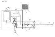
- FIG. 1 is an external view of the in-vivo temperature control system 1 according to the first embodiment.
- the in-vivo temperature control system 1 monitors the internal temperature of the esophagus close to the heart to be ablated when performing ablation with a balloon ablation catheter that heats the inside of the balloon with a high-frequency current, and sets the internal temperature of the esophagus to liquid. Can be used for cooling.
- the biological organ to which the in-vivo temperature control system 1 can be applied is not particularly limited, and may be applied to the pharynx, larynx, lungs, esophagus, stomach, etc., but it is particularly preferable to use it for cooling the inside of the esophagus.
- the in-vivo temperature control system 1 has an in-vivo temperature control device 2 that sends or sucks a temperature-controlled liquid to the catheter 3, and an in-vivo having a hole that can send and suck the liquid in the living body.
- a catheter 3 that can be inserted into the catheter 3, a temperature probe 4 that has a temperature sensor and can be inserted into the catheter 3, a monitor 5 that can display a signal from the temperature probe 4, a pump 21 and a pressure center 22 connected to the raw material. It includes a liquid feed suction tube 6 that connects the body temperature control device 2 and the catheter 3, and a waste liquid unit 7.
- FIG. 2 is a schematic view showing the internal structure of the in-vivo temperature control device 2 shown in FIG.
- the in-vivo temperature control device 2 includes a pump 21 that sends or sucks a liquid to the catheter 3, a pressure sensor 22 that detects the internal pressure of the catheter 3, a liquid storage unit 23 that stores a temperature-controlled liquid, and a temperature probe.
- a control unit 24 that controls the drive of the pump based on the signal detected from 4 or the signal detected from the pressure sensor 22 is provided.
- the pump 21 included in the in-vivo temperature control device 2 is a roller type tube pump, and by rotating the roller of the pump 21 in the forward direction, liquid can be sent from the liquid storage unit 23 to the catheter 3, and the pump can be pumped. By rotating the roller of 21 in the reverse direction, the liquid can be sucked from the tip end portion or the hole of the catheter 3.
- the driving method of the pump used for the pump 21 is not limited, but it is preferable to use a tube pump that can maintain the cleanliness of the liquid to be sent or sucked into the living body and can easily control the flow rate of the liquid. , Roller type and finger type tube pumps are more preferable.
- the in-vivo temperature control device 2 may be provided with a plurality of pumps.
- FIG. 3 shows an in-vivo temperature control device 2 provided with two pumps.
- the in-vivo temperature control device 2 separately includes the liquid feeding pump 211 and the suction pump 212.
- the catheter 3 is provided with a liquid feeding lumen and a multi-lumen having a suction lumen for sucking the liquid
- the liquid feeding pump 211 and the suction pump 212 can be connected to the ports leading to the respective lumens. It is possible to carry out the liquid feeding operation and the liquid suction operation at the same time.
- the liquid can be continuously sent into the living body and the heat-exchanged liquid can be discharged to the outside of the body. Therefore, the temperature in the living body can be efficiently controlled. Can be done.
- the pressure sensor 22 included in the in-vivo temperature control device 2 includes a contact type position displacement meter 221 and an enormous portion 61 of a liquid feed suction tube 6 in contact with the contact type position displacement meter 221.
- the enormous portion 61 of the liquid feed / suction tube 6 is a portion of the liquid feed / suction tube 6 formed in a bag shape, and is designed to expand or contract due to the pressure inside the tube. Therefore, by detecting the displacement amount of the amputation portion 61 as a signal by the contact type position displacement meter 221, the internal pressure of the catheter 3 connected to the liquid feed suction tube 6 via the liquid feed suction tube 6 is measured. can do.
- the detection method of the pressure sensor 22 is not limited, and any detection method may be used as long as it can detect the internal pressure of the catheter 3 during the liquid feeding or suction operation and send it as a signal to the control unit 24.
- a method of adding a diaphragm type in-line pressure sensor or a method of branching a thin tube from the liquid feed suction tube 6 and measuring the pressure of the thin tube may be used.
- the liquid storage unit 23 of the in-vivo temperature control system 1 of the first embodiment is an infusion bag for a generally commercially available physiological saline solution, glucose solution, or the like, and can be contained in the in-vivo temperature control device 2. Structure. Further, in the in-vivo temperature control device 2, a Perche element 231 and an in-device temperature sensor (not shown) for measuring the temperature inside the liquid storage unit 23 are arranged so as to come into contact with the liquid storage unit 23. By controlling the temperature of the Pelche element 231 based on the detected signal, the temperature of the liquid stored in the liquid storage unit 23 can be controlled. When performing catheter ablation with a hot balloon, the temperature of the liquid inside the liquid storage portion 23 is preferably controlled to 0 ° C. to 15 ° C., and more preferably controlled to 0 ° C. to 10 ° C.
- the liquid storage unit 23 may have any form as long as it can store a liquid such as a physiological saline solution, and may be built in the in-vivo temperature control device 2 or outside the in-vivo temperature control device 2. Good. When the liquid storage unit 23 is built in the in-vivo temperature control device 2, it is preferable that the temperature of the liquid in the liquid storage unit 23 can be controlled as described above. As another embodiment from the first embodiment, the infusion bag may be cooled with a cold insulating agent such as ice instead of the Peltier element 231, or the infusion bag frozen in advance may be used while being thawed. Further, as the liquid to be used, purified water or tap water may be used in addition to the physiological saline solution and the glucose solution.
- the in vivo temperature control system of the present invention may be used for this.
- the heat generating resistor may be used to heat the temperature of the liquid stored in the liquid storage unit 23 to 30 to 45 ° C.
- the control unit 24 included in the in-vivo temperature control device 2 controls the pump 21, and discharges the liquid of the liquid storage unit 23 to the outside via the catheter 3 based on the signal detected from the temperature probe 4. Drive the pump 21.
- the specific control operation will be described later.
- the control unit 24 included in the in-vivo temperature control device 2 preferably includes a circuit for controlling the drive of the pump 21 based on the signal detected by the pressure sensor 22.
- the control unit 24 of the in-vivo temperature control system 1 according to the first embodiment has a mechanism capable of numerically converting information regarding the amount of displacement from the liquid feeding / suction tube 6 into pressure information.
- control unit 24 includes a circuit for controlling the internal temperature of the liquid storage unit 23 based on the signal detected from the temperature sensor in the device that measures the temperature inside the liquid storage unit 23. ..
- the catheter 3 is a tubular member that can be inserted into a living body by a nasal or oral approach, and can send or suck a liquid through a lumen through a hole in the tip or surface of the catheter.
- the catheter 3 has a tube portion 31 that can be inserted into a living body and a valved connector 32 that is fixed to the proximal end side of the tube portion 31 in the longitudinal direction.
- the material of the tube portion 31 may be any material as long as it has flexibility that can be inserted into the living body nasally or orally, and for example, polyvinyl chloride, polyurethane, silicone, or the like.
- Thermoplastic resin can be used. Further, in order to confirm the indwelling site in the living body, it is more preferable that a material having X-ray contrast is blended.
- the length of the tube portion 31 is preferably about 200 mm to 1000 mm, the outer diameter is about ⁇ 1.7 mm to 6.0 mm, and the inner diameter is ⁇ 1. It is preferably about 0 mm to 5.0 mm.
- the connector 32 with a valve is fixed to the base end side of the tube portion 31 and can be connected to the liquid feeding and suction tube 6, and has a port 321 for sending or sucking liquid from the tip side of the tube portion 31.
- a valve 322 for fixing the temperature probe 4 when the temperature probe 4 is inserted into the catheter 3 is provided. It is more preferable that the valve 322 can be opened and closed by rotational movement or the like. With the above configuration, the temperature probe 4 can be operated when the valve 322 is opened, and the temperature probe 4 can be fixed when the valve 322 is closed.
- the valved connector 32 of the catheter 3 may include a first port 323 and a second port 324.
- the liquid feeding tube 600 connected to the liquid storage unit 23 and the liquid feeding pump 212 is connected to the first port 323, and the suction tube 601 connected to the suction pump 212 and the liquid feeding pump 212 is connected to the second port 324.
- the liquid feeding line and the suction line can be made independent. As a result, the cooled liquid can always be sent into the living body.
- the catheter 3 is a multi-lumen having a liquid feeding lumen for feeding the liquid and a suction lumen for sucking the liquid
- the first port 323 is a liquid feeding port leading to the liquid feeding lumen.
- the second port 324 may be a suction port leading to a suction lumen.
- the temperature probe 4 is a member that is inserted nasally or orally into a living body and used to measure the internal temperature of a living organ. It is composed of an arranged temperature sensor 42 and a handle portion 43.
- any material may be used as long as it has flexibility that can be inserted into the living body nasally or orally, and polyether blockamide, polyurethane, nylon, polyolefin, etc. may be used.
- Thermoplastic resins such as polyamide and polyether polyamide can be used.
- the outer diameter of the shaft portion 41 is preferably about ⁇ 1.0 mm to 4.0 mm, and even more so as long as it can be inserted into the lumen of the catheter 3.
- the length is preferably about 300 mm to 1100 mm, and when the catheter 3 is inserted into the lumen and used, the temperature sensor 42 on the shaft portion 41 is arranged at a position protruding from the tip end side of the catheter 3. It is preferable to have.
- the shaft portion 41 may have a function that the tip side can be deflected by operating the handle portion 43. Thereby, especially when applied to the esophagus, the risk of invasion into the airway can be reduced when the temperature probe 4 is inserted into the esophagus nasally or orally. Further, since the esophagus is not linear but meandering from the pharynx to the cardia of the stomach, the temperature sensor 42 can be arranged at the target esophageal region by the deflection operation.
- One or more temperature sensors 42 are attached to the tip end side of the shaft portion 41, but the temperature sensors 42 must have a plurality of temperature sensors 42 in order to be able to measure the internal temperature in a wider range in the living organ. Is preferable.
- any material may be used as long as it has good thermal conductivity, and it is still necessary to have X-ray contrast in order to measure the temperature of a portion close to the ablation portion. Good.
- the handle portion 43 includes a connector 431 for connecting to the in-vivo temperature control device 2, and the in-vivo temperature control system 1 according to the first embodiment is the in-vivo temperature control device 2 via a connection cable 44. And the temperature probe 4 are connected.
- the monitor 5 can display the internal temperature information in the living body detected by the temperature probe 4 as a digital number, a bar graph, or a trend graph. Further, the monitor 5 has a function of changing the display color and presenting the temperature change to the operator as visual information when the temperature in the living organ exceeds a preset threshold value. For example, it may be set to change from a cool color to a warm color as the temperature rises from a low temperature to a high temperature. As a result, the temperature detected by the temperature probe 4 arranged in the longitudinal direction in the living body can be confirmed in response to the position in the living body, so that the operator can confirm which part of the living organ has a higher temperature than the other parts. You can get a feel for what you are doing.
- the temperature is indicated by a bar graph in parallel with the display by digital numbers, it is possible to compare the temperature at each part in the living body. Furthermore, it is possible to visually inform the operator that the internal temperature of the living body has risen as the risk of damage to the living organ increases.
- the monitor 5 displays operation information of liquid feeding / sucking, warning information such as errors and alarms generated in the system, operating time, number of times of liquid feeding / sucking, and operating information such as liquid feeding amount. It is preferable to have the function presented in. This makes it possible to visually or audibly inform the operator of the operating status, malfunctioning status, and dangerous status.
- the monitor 5 includes a touch panel display 51, can input various parameters related to the operation of the system, and can transmit the input parameters to the control unit 24 of the in-vivo temperature control device 2.
- the operator can start / stop the operation of the in-vivo temperature control device 2 and set / change various parameters from a remote position.
- the liquid feeding and suction tube 6 delivers the liquid from the liquid storage unit 23 to the catheter 3 via the pump 21 when the liquid is fed, and delivers the liquid from the catheter 3 to the waste liquid unit 7 when the liquid is sucked. It is a tube for.
- the waste liquid portion 7 is a portion for storing unnecessary liquid after sucking the liquid from the body.
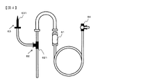
- the liquid feed suction tube 6 included in the in-vivo temperature control system 1 includes a huge portion 61, a flow path switching portion 62, a liquid supply port 63 for connecting to a liquid storage portion 23, and a catheter.
- a connection port 64 for connecting to 3 is provided.
- the enormous portion 61 is a bag-shaped tube, and is designed to expand and contract due to the pressure inside the tube.
- the contact type position displacement meter 221 it is possible to measure the internal pressure of the catheter 3 connected to the liquid feed suction tube 6 via the liquid feed suction tube 6. it can.
- the flow path switching unit 62 in the first embodiment is a three-way check valve 621 and is connected to the primary side of the pump 21.
- the pump 21 rotates in the forward direction, so that the flow path of the three-way check valve 621 switches to the direction in which the liquid storage unit 23 and the pump 21 are connected. Liquid flows to the catheter 3. Further, when the liquid is sucked from the catheter 3, as shown in FIG. 6, the pump 21 rotates in the reverse direction, so that the flow path of the three-way check valve 621 switches to the direction in which the pump 21 and the waste liquid portion 7 are connected. , The sucked liquid is discharged to the waste liquid unit 7.
- the dotted and solid arrows in FIGS. 5 and 6 indicate the rotation direction of the pump 21 and the flow of the liquid.
- a tube provided with a T-shaped branching liquid feed suction tube and two pinch valves may be used as the flow path switching unit 62.
- the in-vivo temperature control device 2 is further provided with a pinch valve, and the control unit 24 switches the flow path by opening and closing the pinch valve in the in-vivo temperature control device 2 in accordance with the pump drive. It is preferable to control.
- the liquid supply port 63 may have any form as long as the liquid can be supplied from the liquid storage unit 23 into the liquid feeding and suction tube 6. Since the liquid storage unit 23 is an infusion bag, the liquid supply port 63 of the first embodiment is preferably a needle 631 that can pierce the infusion bag.
- connection port 64 may have any form as long as it can be connected to the catheter 3, but it is preferably a three-way stopcock. As a result, when the in-vivo temperature control system malfunctions, it is possible to manually send and suck the liquid by connecting a syringe or the like.
- Step 1 Comparison process of temperature information and threshold value
- catheter ablation which cauterizes the heart tissue near the left atrium
- the internal temperature of the adjacent esophagus gradually rises, and each temperature sensor 42 of the temperature probe 4
- the internal temperature of the esophagus measured in is also gradually increased.
- a threshold value of the internal temperature of the esophagus that starts sending the cooled liquid (cooling water) can be set in advance, and the temperature information of the temperature sensor 42 and the above threshold value are always compared.
- Step 2 Liquid (cooling water) liquid feeding operation
- the control unit 24 outputs a liquid feeding speed and liquid feeding time drive command to the pump 21.
- the liquid (cooling water) is sent from the liquid storage unit 23 to the catheter 3 via the liquid feed suction tube 6.
- the liquid (cooling water) reaches the temperature rise portion in the esophagus, the inside of the esophagus can be cooled by heat exchange with the liquid (cooling water).
- the amount of liquid (cooling water) to be fed is controlled by the liquid feeding speed and the liquid feeding time, and can be set in advance in the control unit 24. It is desirable to feed the liquid (cooling water) in a short time, and specifically, it is preferable to feed the liquid at a liquid feeding rate of 1 mL / min to 300 mL / min.
- Step 3 Operation of retaining the liquid (cooling water) in the esophagus
- the operation time of step 3 can be set in advance in the control unit 24, and the process proceeds to step 4 after the set time elapses.
- a method of monitoring the internal temperature of the esophagus and shifting to step 4 when the internal temperature of the esophagus reaches a preset temperature may be used.
- Step 4 Suction operation of the liquid sent into the esophagus
- the entire amount of the liquid sent can be sucked. Further, if the liquid is sucked in a short time, the esophagus may be damaged due to oversuction.
- suction at a suction rate of 1 mL / min to 100 mL / min is preferable.
- the suction time can be set in the control unit 24 in advance, but the suction time at which the entire amount can be sucked may be calculated by dividing the liquid feed amount by the suction speed. Further, the suction speed may be calculated by dividing the liquid feed amount and the suction amount by the suction time, and various modifications can be made.
- the pressure change of the liquid feed suction tube 6 may be used. Specifically, when suction is continued even after the entire amount of liquid is sucked from the esophagus, the esophagus is flattened and the catheter 3 is closed, so that the internal pressure in the liquid feeding suction tube 6 becomes negative pressure. Therefore, the internal pressure in the liquid feeding suction tube 6 is detected by the pressure sensor 22 and the signal is transmitted to the control unit 24 to suck the entire amount of the liquid or at the timing when the liquid in the esophagus runs out.
- the control unit 24 can stop driving the pump 21. More specifically, it is preferable to stop the suction operation when the internal pressure in the liquid feed suction tube 6 is in the range of ⁇ 20 kPaG to ⁇ 90 kPaG.
- step 4 the process returns to step 1 and the steps 1 to 4 are repeated thereafter to maintain an appropriate esophageal temperature.
- the first control operation is a control operation when the internal temperature of the esophagus rises due to thermal ablation of the myocardium by high frequency ablation or the like
- the control unit states that the threshold is reached when the esophageal temperature exceeds the threshold.
- the circuit is created so that 24 can judge.
- the internal temperature of the esophagus drops due to freezing ablation or the like
- the liquid to be sent is changed to heated water, and the threshold value is when the esophageal temperature falls below the threshold value.
- the internal temperature of the esophagus can be controlled by creating a circuit so that the control unit 24 determines that the temperature has been reached.
- the operator operates the touch panel display 51 of the monitor 5 connected to the in-vivo temperature control device 2, so that the liquid feeding start temperature, the liquid feeding amount, the liquid feeding speed, the suction start temperature, and the suction are performed.
- a necessary numerical value among the start time, suction amount, suction speed, suction stop time, and suction stop pressure is set in advance in the control unit 24.
- control unit 24 detects a signal (for example, thermoelectromotive force) from the temperature sensor 42 in the temperature probe 4 connected to the in-vivo temperature control device 2, and the temperature information. Convert to (in-vivo temperature).
- a signal for example, thermoelectromotive force
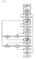
- the control unit 24 determines whether or not at least one of the temperature information acquired from the temperature sensor 42 has reached the liquid feeding start temperature, which is a preset threshold value, that is, the liquid (cooling water) liquid feeding start condition. Judge whether or not the condition is satisfied by comparing the numerical values.
- the control unit 24 drives (forward rotation) the pump 21 to store the liquid. Liquid (cooling water) feeding is started from 23. After the start of liquid (cooling water) feeding, the timer starts counting according to the drive of the pump 21 (timer 1) until the liquid feeding time calculated from the preset liquid feeding amount and liquid feeding speed is reached. , Continue to send liquid (cooling water). After reaching the calculated liquid feeding time, the control unit 24 stops driving the pump 21.
- control unit 24 continues to control the in-vivo temperature because it is within the normal temperature range that does not require liquid feeding for temperature control. It is acquired and it is judged whether or not the condition for starting the liquid (cooling water) transfer is satisfied.
- the control unit 24 After the liquid (cooling water) has been sent, the control unit 24 starts counting the timer (timer 2), and whether or not the count of the timer 2 reaches the suction start time which is a preset threshold value, that is, It is determined whether or not the first start condition of suction is satisfied.
- the control unit 24 drives (reverse rotation) the pump 21 to start sucking the liquid from the living body.
- the control unit 24 then reaches at least one of the acquired in-vivo temperatures to be equal to or higher than the suction start temperature which is a preset threshold value.
- the suction is performed, that is, whether or not the second start condition of suction is satisfied.
- the second start condition of suction when the temperature in the living body is lower than the suction start temperature which is a preset threshold value, the timer 2 count is started again to check whether or not the first start condition of suction is satisfied. to decide.
- the control unit 24 determines whether or not the liquid feeding start condition is satisfied.
- the control unit 24 drives the pump 21 (forward rotation) and starts sending liquid from the liquid storage unit 23.
- the control unit 24 drives (reverse rotation) the pump 21 to start sucking the liquid from the living body.
- the control unit 24 After the liquid feeding is completed, the control unit 24 starts counting the timer 2 and repeats the liquid feeding operation until the first suction start condition and the second suction start condition are satisfied, but the suction starts. If the liquid is repeatedly sent without performing the above, the risk of aspiration due to overdose of the liquid increases, so it is desirable to sound an alarm to notify the operator of the abnormality. If it is not determined that the liquid feeding start condition is satisfied, the control unit 24 continues to determine whether or not the suction start condition is satisfied, and then whether or not the liquid feeding start condition is satisfied.
- the timer count is started according to the drive of the pump 21 (timer 3), and whether or not the count of the timer 3 reaches the preset suction stop time, that is, the first stop condition of suction is satisfied.
- the suction stop time may be calculated from a preset suction amount and suction speed.
- the control unit 24 stops driving the pump 21.
- the control unit 24 calculates the tube internal pressure based on the signal detected by the pressure sensor 22, and whether the tube internal pressure is equal to or less than the suction stop pressure, which is a preset threshold value. Whether or not, that is, whether or not the second stop condition of suction is satisfied is determined.
- the control unit 24 stops driving the pump 21.
- the control unit 24 determines whether or not it is a condition for starting liquid (cooling water) feeding.
- the control unit 24 reversely rotates the drive of the pump 21 in order to control the in-vivo temperature within the normal temperature range. The temperature is changed to forward rotation, and the liquid (cooling water) is started to be sent from the liquid storage unit 23.
- the control unit 24 repeatedly determines whether or not the suction stop condition is satisfied, and then whether or not the liquid feeding start condition is satisfied.
- control unit 24 determines again whether or not the condition for starting the liquid (cooling water) feeding is satisfied, and continues in the living body according to the above flow until the operator stops the automatic operation. Control the temperature.
- a plurality of esophageal temperature threshold values and a liquid feeding rate corresponding to the threshold values can be set in advance in the control unit 24, and a liquid (cooling water) that has been continuously cooled according to the set temperature can be fed. ..
- FIG. 9 shows a case where the setting is made between three stages, the number of stages can be arbitrarily set by the operator.
- Step 1 Comparison process of temperature information and threshold value
- catheter ablation which cauterizes the heart tissue near the left atrium
- the temperature of the adjacent esophagus gradually rises, and each temperature sensor 42 of the temperature probe 4
- the measured esophageal temperature also gradually rises.
- the control unit 24 constantly compares the temperature information of each temperature sensor 42 with the plurality of threshold values.
- Step 2 Liquid (cooling water) feeding operation
- the control unit 24 sends the pump 21 to the pump 21.
- a drive command for the first liquid feeding rate is output, and the cooled liquid (cooling water) is sent from the liquid storage unit 23 to the catheter 3 via the liquid feeding suction tube 6.
- the control unit 24 Outputs a drive command for the second liquid feeding rate to the pump 21. After that, it shifts to the third setting according to the rise in the esophageal temperature.
- the pump 21 is controlled so as to output a drive command for the N-1 liquid feeding speed.
- the liquid (cooling water) feeding is stopped.
- the liquid (cooling water) can be sent at an appropriate flow rate according to the rise and fall of the internal temperature of the esophagus, and the inside of the esophagus is cooled more effectively. be able to.
- the first liquid feeding speed ⁇ second liquid feeding speed ⁇ ... ⁇ Nth liquid feeding speed and the liquid (cooling water) feeding speed may increase as the esophageal temperature rises.
- the liquid feeding rate before exceeding the threshold value it is preferable to set the liquid feeding rate before exceeding the threshold value to a low speed (specifically, 1 mL / min to 50 mL / min). This makes it possible to reduce the risk of aspiration due to overdose of liquid (cooling water).
- Step 3 Suction operation of the liquid sent into the esophagus
- the suction operation should be performed when the integrated value of the amount of liquid sent exceeds the set amount.
- the cumulative liquid feed amount for starting suction of the liquid can be set in advance in the control unit 24 as the cumulative liquid feed amount for starting suction. Further, as in the first control method, if the liquid is sucked in a short time, oversuction may cause damage to the esophagus. Therefore, it is preferable to set the liquid feeding speed to be lower than the liquid feeding speed.
- the pressure change of the liquid feed suction tube 6 may be used. Specifically, when suction is continued even after the entire amount of liquid is sucked from the esophagus, the esophagus is flattened and the catheter 3 is closed, so that the internal pressure in the liquid feeding suction tube 6 becomes negative pressure. Therefore, the internal pressure in the liquid feeding suction tube 6 is detected by the pressure sensor 22 and the signal is transmitted to the control unit 24, so that the control unit 24 pumps at the timing when all the liquid is sucked or the liquid in the esophagus runs out. The drive of 21 can be stopped. More specifically, it is preferable to stop the suction operation when the internal pressure in the liquid feed suction tube 6 is in the range of ⁇ 20 kPaG to ⁇ 90 kPaG.
- the process returns to step 1 and the steps 1 to 3 are repeated thereafter to maintain an appropriate esophageal temperature.
- the second control method is a control method when the internal temperature of the esophagus rises due to thermal ablation of the myocardium by high frequency ablation or the like, the control unit states that the threshold is reached when the esophageal temperature exceeds the threshold. The circuit is created so that 24 can judge.
- the liquid to be sent is changed to heated water, and the case where the esophageal temperature becomes less than the threshold value is set as the threshold value.
- the internal temperature of the esophagus can be controlled by creating a circuit so that the control unit 24 determines that the temperature has been reached.
- the operator operates the touch panel display 51 of the monitor 5 connected to the in-vivo temperature control device 2, thereby setting the threshold value of the esophageal temperature of the first to N and the liquid feeding speed of the first to N.
- the suction start integrated liquid feeding amount and the suction speed are set in advance in any of the necessary numerical values in the control unit 24.
- the Nth liquid feeding rate is the rate at which the liquid is sent when the threshold value of the Nth esophageal temperature is reached.
- control unit 24 detects a signal (for example, thermoelectromotive force) from the temperature sensor 42 in the temperature probe 4 connected to the in-vivo temperature control device 2, and the temperature information. Convert to (in-vivo temperature).
- a signal for example, thermoelectromotive force
- the control unit 24 determines whether or not at least one of the acquired in-vivo temperatures has reached the esophageal temperature, which is a preset first to Nth threshold value, that is, the delivery of liquid (cooling water). Determine if the liquid start condition is met. Specifically, when the temperature in the living body reaches the esophageal temperature which is the N-1 threshold value and does not reach the esophageal temperature which is the Nth threshold value, the control unit 24 drives the pump 21 (forward rotation). ), And the liquid is fed at the N-1 liquid feeding speed.
- the control unit 24 stops the driving of the pump 21. Further, when the temperature in the living body reaches the esophageal temperature which is the Nth threshold value, the control unit 24 drives the drive of the pump 21 to feed the liquid at the Nth liquid feeding speed.
- the control unit 24 calculates the total liquid feeding amount from the liquid feeding speed and the liquid feeding time, and determines whether or not the total liquid feeding amount has reached the suction start integrated liquid feeding amount.
- the control unit 24 switches the pump 21 from forward rotation to reverse rotation and starts sucking liquid from the living body.
- the control unit 24 calculates the internal pressure of the tube based on the signal detected by the pressure sensor 22, and sucks the entire amount of the liquid until the internal pressure of the tube becomes equal to or lower than the suction stop pressure which is a preset threshold value. Alternatively, continue suction until the fluid in the esophagus is exhausted.
- control unit 24 determines again whether or not the condition for starting the liquid (cooling water) feeding is satisfied, and continues in the living body according to the above flowchart until the operator stops the automatic operation. Control the temperature.
- the in-vivo temperature control system 1 of the present invention shown in FIGS. 1 and 2 was produced.
- the pump 21 is a roller type tube pump that is used for both liquid feeding and suction, and the liquid feeding speed and suction speed can be arbitrarily set in the range of 1 mL / min to 300 mL / min.
- a contact type position displacement meter 221 was used as the pressure sensor 22, and the internal force of the liquid feed suction tube 6 could be measured in the range of -80 kPaG to 150 kPaG.
- a 500 mL physiological saline solution bag is used in the liquid storage unit 23, and the physiological saline solution bag is cooled by using the Peltier element 231 to keep the temperature of the cooling water (physiological saline solution) within the range of 0 ° C. to 10 ° C. Held in.
- the control unit 24 incorporates a circuit capable of implementing the first control method. Specifically, when the temperature of at least one point among the temperatures obtained from the temperature sensor 42 reaches a preset threshold value, the pump 21 is controlled to supply the liquid with the set amount and flow rate of the liquid storage unit 23. A control method for discharging the liquid to the outside via the catheter 3 was incorporated into the control unit 24. Further, when the suction start time or the suction start temperature reaches the set value or less, the control method of controlling the pump 21 to start the suction of the liquid from the living body and the set suction stop time or the pressure obtained from the pressure sensor 22. The control unit 24 incorporates a control method for stopping the suction of the liquid when the suction stop pressure, which is a preset threshold value, is reached.
- the tube portion 31 of the catheter 3 has an outer diameter of 4.7 mm and an inner diameter of 3.3 mm, and is provided with a port 321 for connecting to the liquid feed suction tube 6 and a valve 322 for fixing the temperature probe 4 at the hand portion.
- a connector 32 with a valve was arranged.
- the shaft portion 41 of the temperature probe 4 has an outer diameter of 2.0 mm, and six temperature sensors 42 are arranged at positions 20 mm from the tip side of the shaft portion 41.
- the liquid feed suction tube 6 detects the internal pressure of the bottle needle for connecting to the physiological saline bag, the three-way check valve at the flow path switching part, the tube part 31 connected to the pump 21, and the liquid feed suction tube 6.
- a connecting portion for connecting to the ampulla portion 61, the contact type position displacement meter 221 and the catheter 3 was arranged. (Cooling effect confirmation experiment by sending and sucking cooling water) After inserting and immobilizing the temperature sensor 42 of the temperature probe 4 so as to protrude from the tip of the catheter 3, it was placed in the simulated esophagus.
- the liquid feed suction tube 6 is connected to the in-vivo temperature control device 2 and the catheter 3, and when the temperature of any one of the six temperature sensors 42 reaches 38 ° C., 15 mL of cooling water flows out.
- the solution was set to be delivered at 300 mL / min. Further, when the suction start time, suction start temperature, suction amount, suction speed, and suction stop pressure are set respectively, and any one of the six temperature sensors 42 reaches 36 ° C. for 30 seconds after the liquid is sent.
- the cooling water was sucked at a flow rate of 60 mL / min, and the operation was set in advance so that the suction of the cooling water was stopped for 20 seconds from the start of suction or when the pressure sensor 22 reached ⁇ 50 kPaG.
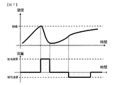
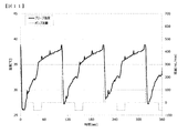
- FIG. 11 shows the simulated esophageal temperature detected by the temperature probe 4 when the automatic operation of the in-vivo temperature control system 1 was started after controlling the internal temperature of the simulated esophagus to 40 ° C., and the liquid feed flow rate of the pump 21. And the suction flow rate are shown.
- the control unit 24 determines that the signal detected from the temperature probe has exceeded the threshold value, and starts the liquid feeding operation of the pump 21 based on the pre-programmed operation to cool the pump 21. Water is pumped into the esophagus. From this, it can be seen that the internal temperature of the esophagus was temporarily cooled to about 27 to 33 ° C.
- the cooling water is sucked based on a pre-programmed operation, and the temperature probe 4 is warmed by the body temperature. Therefore, the measured temperature of the temperature probe 4 gradually rises, and when the temperature reaches 38 ° C., the cooling water is replenished.
- the liquid is sent. From FIG. 11, it was confirmed that the internal temperature of the esophagus was always cooled to 38 ° C. or lower by repeating the liquid feeding and suction operations.
- the present invention provides a system capable of automatically controlling the internal temperature of the body cavity when the internal temperature of the body cavity changes during the operation in the medical field.
Landscapes
- Health & Medical Sciences (AREA)
- Life Sciences & Earth Sciences (AREA)
- Engineering & Computer Science (AREA)
- Surgery (AREA)
- General Health & Medical Sciences (AREA)
- Veterinary Medicine (AREA)
- Public Health (AREA)
- Animal Behavior & Ethology (AREA)
- Biomedical Technology (AREA)
- Heart & Thoracic Surgery (AREA)
- Molecular Biology (AREA)
- Medical Informatics (AREA)
- Physics & Mathematics (AREA)
- Nuclear Medicine, Radiotherapy & Molecular Imaging (AREA)
- Plasma & Fusion (AREA)
- Otolaryngology (AREA)
- Vascular Medicine (AREA)
- Pathology (AREA)
- Cardiology (AREA)
- Biophysics (AREA)
- Anesthesiology (AREA)
- Hematology (AREA)
- Gastroenterology & Hepatology (AREA)
- Physiology (AREA)
- Mechanical Engineering (AREA)
- General Engineering & Computer Science (AREA)
- Endocrinology (AREA)
- Oral & Maxillofacial Surgery (AREA)
- Media Introduction/Drainage Providing Device (AREA)
- Measuring And Recording Apparatus For Diagnosis (AREA)
- Surgical Instruments (AREA)
Abstract
Description
(1) 生体内に挿入可能なカテーテルと、温度センサを有する上記カテーテルに挿入可能な温度プローブと、温度制御された液体を貯留する液体貯留部と、上記液体貯留部からの液体を上記カテーテルに供給するポンプと、上記温度プローブから検知された信号に基づいて上記ポンプの駆動を制御する制御部と、を備え、上記制御部は、上記信号が予め設定した閾値に達した場合に上記ポンプを制御し、上記ポンプは、上記液体貯留部内の液体を上記カテーテルを介して外部に放出するよう駆動する、生体内温度制御システム。
(2) 上記制御部は、予め設定した時間又は温度に達した場合に上記ポンプを制御し、上記ポンプは、外部の液体を上記カテーテルを介して吸引するよう駆動する、(1)記載の生体内温度制御システム。
(3) 上記カテーテルの内部圧力を検出する圧力センサを備え、上記制御部は、上記圧力センサで検知された信号に基づいて上記ポンプの駆動を制御する、(1)又は(2)記載の生体内温度制御システム。
(4) 上記制御部は、液体の送液時の回転数よりも液体の吸引時の回転数が小さくなるようにポンプを駆動させる、(1)~(3)のいずれか記載の生体内温度制御システム。
(5) 上記温度プローブから検知された信号をデジタル数字、バーグラフ又はトレンドグラフで表記するモニタを備え、上記温度プローブから検知された信号が予め設定した閾値を越えた場合に上記モニタ上のデジタル数字、バーグラフ又はトレンドグラフの表示色の変化によって操作者に知らせる手段を有する、(1)~(4)のいずれか記載の生体内温度制御システム。
(6) 上記ポンプは、送液用ポンプ及び吸引用ポンプであり、上記制御部は、液体の送液時に上記送液用ポンプを駆動させ、液体の吸引時に上記吸引用ポンプを駆動させる、(1)~(5)のいずれか記載の生体内温度制御システム。
(7) 生体内に挿入可能なカテーテルと、温度センサを有する上記カテーテルに挿入可能な温度プローブと、温度制御された液体を貯留する液体貯留部と、上記液体貯留部からの液体を上記カテーテルに供給するポンプと、上記温度プローブから検知された信号に基づいて上記ポンプの駆動を制御する制御部と、を備えた生体内温度制御システムを制御する方法であり、上記制御部が上記温度プローブから検知された信号と予め設定した閾値とを比較するステップと、上記信号が上記閾値に達したと判断した場合に、上記制御部が上記カテーテルを介して上記液体貯留部内の液体を外部に放出するように上記ポンプを駆動させるステップと、を含む、方法。
<第1の実施形態>
図1は、第1の実施形態に係る生体内温度制御システム1の外観図である。生体内温度制御システム1は、例えば、高周波電流でバルーン内を加熱するバルーンアブレーションカテーテルによりアブレーション術を行う際、アブレーション対象の心臓に近接する食道の内部温度を監視するとともに、食道の内部温度を液体により冷却するために用いることができる。生体内温度制御システム1を適用可能な生体器官は特に限定されるものではなく、咽頭、喉頭、肺、食道及び胃等に適用してもよいが、特に食道内部の冷却に用いることが好ましい。
左心房近傍で心臓組織を焼灼するカテーテルアブレーション術が開始されると、近接している食道の内部温度が徐々に上昇し、温度プローブ4の各温度センサ42で測定される食道の内部温度も徐々に上昇する。制御部24では冷却された液体(冷却水)の送液を開始する食道の内部温度の閾値が予め設定可能であり、温度センサ42の温度情報と上記閾値の比較処理が常に行われる。
複数の温度センサ42の少なくとも1つの温度情報が上記閾値に達すると、制御部24からポンプ21に送液速度と送液時間の駆動指令が出力され、液体貯留部23から送液吸引兼用チューブ6を介して、液体(冷却水)がカテーテル3に送液される。食道内の温度上昇部位に液体(冷却水)が到達することで、液体(冷却水)との熱交換により食道内を冷却することができる。液体(冷却水)の送液量は、送液速度と送液時間で管理されており、予め制御部24に設定が可能である。液体(冷却水)は短時間で送液することが望ましく、具体的には1mL/min~300mL/minの送液速度での送液が好ましい。
ステップ3の動作時間は予め制御部24に設定が可能であり、設定時間の経過後にステップ4に移行する。また別の方法として、食道の内部温度を監視し、食道の内部温度が予め設定した温度に達したタイミングでステップ4に移行する方法を用いてもよい。
送液した液体が気管に流出することによる誤嚥を防止するためには、送液した液体を全量吸引できることが好ましい。また、短時間で液体を吸引すると過吸引により食道損傷を招く可能性があるため、送液速度よりも低速に設定することが好ましい。具体的には、1mL/min~100mL/minの吸引速度での吸引が好ましい。吸引時間は、予め制御部24に設定することができるが、送液量を吸引速度で除算することで全量吸引可能な吸引時間を算出してもよい。また、送液量や吸引量を吸引時間で除算することで吸引速度を算出してもよく、種々の改変が可能である。
左心房近傍で心臓組織を焼灼するカテーテルアブレーション術が開始されると、近接している食道の温度が徐々に上昇し、温度プローブ4の各温度センサ42で測定される食道温度も徐々に上昇する。制御部24では各温度センサ42の温度情報と上記複数の閾値の比較処理が常に行われる。
測定される温度センサ42の少なくとも1点の温度情報が第1の食道温度の閾値(第1の閾値)に達すると、制御部24からポンプ21に第1の送液速度の駆動指令が出力され、液体貯留部23から送液吸引兼用チューブ6を介して、冷却された液体(冷却水)がカテーテル3に送液される。さらに、カテーテルアブレーション術が進み食道の内部温度が上昇し、測定される食道の内部温度の少なくとも1点の温度情報が第2の食道温度の閾値(第2の閾値)に達すると、制御部24からポンプ21に第2の送液速度の駆動指令が出力される。以降、食道温度の上昇に応じて第3の設定に移行する。
持続的に送液した液体による誤嚥を防止するためには、送液量の積算値が設定した量を超えた場合に吸引動作をすることが好ましい。液体の吸引を始める積算送液量は、吸引開始積算送液量として、予め制御部24に設定することができる。また、第1の制御方法と同様に、短時間で液体を吸引すると過吸引により食道の損傷を招く可能性があるため、送液速度よりも低速に設定することが好ましい。
送液吸引兼用チューブ6に接続するためのポート321と、温度プローブ4を固定するための弁322を備えた弁付きコネクタ32を配置した。
(冷却水の送液及び吸引による冷却効果確認実験)
カテーテル3の先端部から突出するように温度プローブ4の温度センサ42を挿入及び固定化した後、模擬食道内に留置した。その後、送液吸引兼用チューブ6を、生体内温度制御装置2とカテーテル3に接続し、6点の温度センサ42のいずれか1点の温度が38℃に達したときに15mLの冷却水が流量300mL/minで送液されるように設定した。また、吸引開始時間、吸引開始温度、吸引量、吸引速度及び吸引停止圧力の数値をそれぞれ設定し、送液後30秒間又は6点の温度センサ42のいずれか1点が36℃に達したときに冷却水を流量60mL/min吸引し、吸引開始から20秒間又は圧力センサ22が-50kPaGに達した場合、冷却水の吸引が停止するように、予め動作を設定した。
4・・・温度プローブ、5・・・モニタ、6・・・送液吸引兼用チューブ、7・・・廃液部、21・・・ポンプ、22・・・圧力センサ、23・・・液体貯留部、24・・制御部、
31・・・チューブ部、32・・・弁付きコネクタ、41・・・シャフト部、42・・・温度センサ、43・・・ハンドル部、44・・・接続ケーブル、51・・・タッチパネルディスプレイ、61・・・膨大部、62・・・流路切替部、63・・・液体供給ポート、64・・・接続ポート、211・・・送液用ポンプ、212・・・吸引用ポンプ、221・・・接触型位置変位計、231・・・ペルチェ素子、321・・・ポート、322・・・弁、323・・・第1のポート、324・・・第2のポート、431・・・コネクタ、600・・・送液用チューブ、601・・・吸引用チューブ、621・・・三方チェックバルブ、631・・・ニードル
Claims (7)
- 生体内に挿入可能なカテーテルと、
温度センサを有する前記カテーテルに挿入可能な温度プローブと、
温度制御された液体を貯留する液体貯留部と、
前記液体貯留部からの液体を前記カテーテルに供給するポンプと、
前記温度プローブから検知された信号に基づいて前記ポンプの駆動を制御する制御部と、を備え、
前記制御部は、前記信号が予め設定した閾値に達した場合に前記ポンプを制御し、
前記ポンプは、前記液体貯留部内の液体を前記カテーテルを介して外部に放出するよう駆動する、
生体内温度制御システム。 - 前記制御部は、予め設定した時間又は温度に達した場合に前記ポンプを制御し、
前記ポンプは、外部の液体を前記カテーテルを介して吸引するよう駆動する、
請求項1記載の生体内温度制御システム。 - 前記カテーテルの内部圧力を検出する圧力センサを備え、
前記制御部は、前記圧力センサで検知された信号に基づいて前記ポンプの駆動を制御する、
請求項1又は2記載の生体内温度制御システム。 - 前記制御部は、液体の送液時の回転数よりも液体の吸引時の回転数が小さくなるようにポンプを駆動させる、
請求項1~3のいずれか一項記載の生体内温度制御システム。 - 前記温度プローブから検知された信号をデジタル数字、バーグラフ又はトレンドグラフで表記するモニタを備え、
前記温度プローブから検知された信号が予め設定した閾値を越えた場合に前記モニタ上のデジタル数字、バーグラフ又はトレンドグラフの表示色の変化によって操作者に知らせる手段を有する、
請求項1~4のいずれか一項記載の生体内温度制御システム。 - 前記ポンプは、送液用ポンプ及び吸引用ポンプであり、
前記制御部は、液体の送液時に前記送液用ポンプを駆動させ、液体の吸引時に前記吸引用ポンプを駆動させる、
請求項1~5のいずれか一項記載の生体内温度制御システム。 - 生体内に挿入可能なカテーテルと、
温度センサを有する前記カテーテルに挿入可能な温度プローブと、
温度制御された液体を貯留する液体貯留部と、
前記液体貯留部からの液体を前記カテーテルに供給するポンプと、
前記温度プローブから検知された信号に基づいて前記ポンプの駆動を制御する制御部と、を備えた生体内温度制御システムを制御する方法であり、
前記制御部が前記温度プローブから検知された信号と予め設定した閾値とを比較するステップと、
前記信号が前記閾値に達したと判断した場合に、前記制御部が前記カテーテルを介して前記液体貯留部内の液体を外部に放出するように前記ポンプを駆動させるステップと、
を含む、方法。
Priority Applications (7)
| Application Number | Priority Date | Filing Date | Title |
|---|---|---|---|
| KR1020227004227A KR20220082806A (ko) | 2019-10-24 | 2020-10-23 | 생체내 온도 제어 시스템 |
| US17/770,102 US20220378499A1 (en) | 2019-10-24 | 2020-10-23 | In vivo temperature control system |
| AU2020371402A AU2020371402A1 (en) | 2019-10-24 | 2020-10-23 | In vivo temperature control system |
| JP2020560511A JP7663834B2 (ja) | 2019-10-24 | 2020-10-23 | 生体内温度制御システム |
| EP20878176.5A EP4049602A4 (en) | 2019-10-24 | 2020-10-23 | IN-VIVO TEMPERATURE CONTROL SYSTEM |
| CN202080073693.0A CN114554992B (zh) | 2019-10-24 | 2020-10-23 | 生物体内温度控制系统 |
| CA3157402A CA3157402A1 (en) | 2019-10-24 | 2020-10-23 | In vivo temperature control system |
Applications Claiming Priority (2)
| Application Number | Priority Date | Filing Date | Title |
|---|---|---|---|
| JP2019193137 | 2019-10-24 | ||
| JP2019-193137 | 2019-10-24 |
Publications (1)
| Publication Number | Publication Date |
|---|---|
| WO2021079974A1 true WO2021079974A1 (ja) | 2021-04-29 |
Family
ID=75620120
Family Applications (1)
| Application Number | Title | Priority Date | Filing Date |
|---|---|---|---|
| PCT/JP2020/039848 Ceased WO2021079974A1 (ja) | 2019-10-24 | 2020-10-23 | 生体内温度制御システム |
Country Status (9)
| Country | Link |
|---|---|
| US (1) | US20220378499A1 (ja) |
| EP (1) | EP4049602A4 (ja) |
| JP (1) | JP7663834B2 (ja) |
| KR (1) | KR20220082806A (ja) |
| CN (1) | CN114554992B (ja) |
| AU (1) | AU2020371402A1 (ja) |
| CA (1) | CA3157402A1 (ja) |
| TW (1) | TW202126252A (ja) |
| WO (1) | WO2021079974A1 (ja) |
Cited By (2)
| Publication number | Priority date | Publication date | Assignee | Title |
|---|---|---|---|---|
| JPWO2022211011A1 (ja) * | 2021-03-31 | 2022-10-06 | ||
| WO2023080148A1 (ja) * | 2021-11-04 | 2023-05-11 | 東レ株式会社 | 生体内温度制御システム |
Families Citing this family (5)
| Publication number | Priority date | Publication date | Assignee | Title |
|---|---|---|---|---|
| JPWO2022211012A1 (ja) * | 2021-03-31 | 2022-10-06 | ||
| US12135023B2 (en) * | 2022-03-09 | 2024-11-05 | Blue-White Industries, Ltd. | Input/output calibration of pump |
| CN115778517A (zh) * | 2022-11-14 | 2023-03-14 | 上海导向医疗系统有限公司 | 智能温度调控及应急处理的尿道保温装置及应急处理方法 |
| CN117243689B (zh) * | 2023-09-15 | 2024-04-19 | 南京康友医疗科技有限公司 | 一种防止组织碳化的微波消融系统 |
| CN118743602A (zh) * | 2024-07-10 | 2024-10-08 | 中国人民解放军总医院海南医院 | 用于热射病发病人员的快速检测设备 |
Citations (8)
| Publication number | Priority date | Publication date | Assignee | Title |
|---|---|---|---|---|
| JP2000300666A (ja) * | 1999-04-23 | 2000-10-31 | Olympus Optical Co Ltd | 腹腔内灌流加温装置 |
| US20080161890A1 (en) * | 2007-01-03 | 2008-07-03 | Boston Scientific Scimed, Inc. | Methods, systems, and apparatuses for protecting esophageal tissue during ablation |
| JP2009504284A (ja) | 2005-08-19 | 2009-02-05 | ネーヴ,ヴェルナー,フランソワ デ | 心臓の熱切除治療を援助するための装置ならびに方法 |
| JP2012515612A (ja) * | 2009-01-20 | 2012-07-12 | アドヴァンスト カーディアック セラピューティクス インコーポレイテッド | 臓器の組織アブレーションの際に別の臓器の熱傷を最小限にするための方法及び装置 |
| JP2014176693A (ja) * | 2013-03-14 | 2014-09-25 | Biosense Webster (Israel) Ltd | 噴霧灌流を有するカテーテル |
| JP2016119936A (ja) | 2014-12-24 | 2016-07-07 | 日本ライフライン株式会社 | 温度測定装置およびカテーテルシステム |
| WO2018160454A1 (en) * | 2017-02-28 | 2018-09-07 | University Of Florida Research Foundation, Inc. | Controlling esophageal temperature during cardiac ablation |
| JP2019010500A (ja) | 2017-04-28 | 2019-01-24 | レックス メディカル リミテッド パートナーシップ | センサを備えた食道リトラクタ |
Family Cites Families (7)
| Publication number | Priority date | Publication date | Assignee | Title |
|---|---|---|---|---|
| US5836909A (en) * | 1996-09-13 | 1998-11-17 | Cosmescu; Ioan | Automatic fluid control system for use in open and laparoscopic laser surgery and electrosurgery and method therefor |
| US8512387B2 (en) * | 2007-09-07 | 2013-08-20 | Robert S. Fishel | Esophageal cooling system for ablation procedures associated with cardiac arrhythmias |
| US9980765B2 (en) * | 2010-02-15 | 2018-05-29 | The General Hospital Corporation | Methods and devices for selective disruption of visceral fat by controlled cooling |
| EP2642913B1 (en) | 2010-11-27 | 2024-02-21 | Boston Scientific Scimed, Inc. | Ablation and temperature measurement devices |
| WO2013120042A1 (en) * | 2012-02-10 | 2013-08-15 | Intermountain Invention Management, Llc | Esophageal heat sensors |
| US20190380761A1 (en) * | 2017-02-28 | 2019-12-19 | University Of Florida Research Foundation, Inc. | Controlling esophageal temperature during cardiac ablation |
| EP3743023A4 (en) * | 2018-01-23 | 2021-10-27 | E-Safe Medical, Inc. | ESOPHAGEAL TUBES AND RELATED PROCESSES |
-
2020
- 2020-10-23 EP EP20878176.5A patent/EP4049602A4/en active Pending
- 2020-10-23 WO PCT/JP2020/039848 patent/WO2021079974A1/ja not_active Ceased
- 2020-10-23 US US17/770,102 patent/US20220378499A1/en active Pending
- 2020-10-23 TW TW109136826A patent/TW202126252A/zh unknown
- 2020-10-23 AU AU2020371402A patent/AU2020371402A1/en not_active Abandoned
- 2020-10-23 KR KR1020227004227A patent/KR20220082806A/ko not_active Withdrawn
- 2020-10-23 JP JP2020560511A patent/JP7663834B2/ja active Active
- 2020-10-23 CN CN202080073693.0A patent/CN114554992B/zh active Active
- 2020-10-23 CA CA3157402A patent/CA3157402A1/en active Pending
Patent Citations (8)
| Publication number | Priority date | Publication date | Assignee | Title |
|---|---|---|---|---|
| JP2000300666A (ja) * | 1999-04-23 | 2000-10-31 | Olympus Optical Co Ltd | 腹腔内灌流加温装置 |
| JP2009504284A (ja) | 2005-08-19 | 2009-02-05 | ネーヴ,ヴェルナー,フランソワ デ | 心臓の熱切除治療を援助するための装置ならびに方法 |
| US20080161890A1 (en) * | 2007-01-03 | 2008-07-03 | Boston Scientific Scimed, Inc. | Methods, systems, and apparatuses for protecting esophageal tissue during ablation |
| JP2012515612A (ja) * | 2009-01-20 | 2012-07-12 | アドヴァンスト カーディアック セラピューティクス インコーポレイテッド | 臓器の組織アブレーションの際に別の臓器の熱傷を最小限にするための方法及び装置 |
| JP2014176693A (ja) * | 2013-03-14 | 2014-09-25 | Biosense Webster (Israel) Ltd | 噴霧灌流を有するカテーテル |
| JP2016119936A (ja) | 2014-12-24 | 2016-07-07 | 日本ライフライン株式会社 | 温度測定装置およびカテーテルシステム |
| WO2018160454A1 (en) * | 2017-02-28 | 2018-09-07 | University Of Florida Research Foundation, Inc. | Controlling esophageal temperature during cardiac ablation |
| JP2019010500A (ja) | 2017-04-28 | 2019-01-24 | レックス メディカル リミテッド パートナーシップ | センサを備えた食道リトラクタ |
Non-Patent Citations (1)
| Title |
|---|
| See also references of EP4049602A4 |
Cited By (3)
| Publication number | Priority date | Publication date | Assignee | Title |
|---|---|---|---|---|
| JPWO2022211011A1 (ja) * | 2021-03-31 | 2022-10-06 | ||
| JP7779258B2 (ja) | 2021-03-31 | 2025-12-03 | 東レ株式会社 | 生体内温度制御システム |
| WO2023080148A1 (ja) * | 2021-11-04 | 2023-05-11 | 東レ株式会社 | 生体内温度制御システム |
Also Published As
| Publication number | Publication date |
|---|---|
| US20220378499A1 (en) | 2022-12-01 |
| KR20220082806A (ko) | 2022-06-17 |
| AU2020371402A1 (en) | 2022-06-02 |
| CN114554992B (zh) | 2024-08-06 |
| JP7663834B2 (ja) | 2025-04-17 |
| EP4049602A4 (en) | 2023-11-22 |
| TW202126252A (zh) | 2021-07-16 |
| JPWO2021079974A1 (ja) | 2021-04-29 |
| CN114554992A (zh) | 2022-05-27 |
| CA3157402A1 (en) | 2021-04-29 |
| EP4049602A1 (en) | 2022-08-31 |
Similar Documents
| Publication | Publication Date | Title |
|---|---|---|
| JP7663834B2 (ja) | 生体内温度制御システム | |
| US12268631B2 (en) | Devices and methods for protecting esophageal tissue from thermal injury | |
| CN104188752B (zh) | 控制患者体温的装置和方法 | |
| KR102245697B1 (ko) | 조직의 치료를 위한 열 절제 시스템,장치 및 방법 | |
| US9326890B2 (en) | Devices and methods for controlling patient temperature | |
| EP2882362A1 (en) | Ablation systems, devices and methods for the treatment of tissue | |
| JP7206036B2 (ja) | 食道カテーテル及び食道温制御システム | |
| CN111491581A (zh) | 消融程序期间使用的计时系统 | |
| JP7779258B2 (ja) | 生体内温度制御システム | |
| US20240173467A1 (en) | In vivo temperature control system | |
| WO2023080148A1 (ja) | 生体内温度制御システム | |
| US20180325726A1 (en) | Devices, systems, and methods for controlling temperature in pediatric subjects | |
| JP7242168B2 (ja) | 食道カテーテル |
Legal Events
| Date | Code | Title | Description |
|---|---|---|---|
| ENP | Entry into the national phase |
Ref document number: 2020560511 Country of ref document: JP Kind code of ref document: A |
|
| 121 | Ep: the epo has been informed by wipo that ep was designated in this application |
Ref document number: 20878176 Country of ref document: EP Kind code of ref document: A1 |
|
| ENP | Entry into the national phase |
Ref document number: 3157402 Country of ref document: CA |
|
| NENP | Non-entry into the national phase |
Ref country code: DE |
|
| ENP | Entry into the national phase |
Ref document number: 2020878176 Country of ref document: EP Effective date: 20220524 |
|
| ENP | Entry into the national phase |
Ref document number: 2020371402 Country of ref document: AU Date of ref document: 20201023 Kind code of ref document: A |