WO2021085144A1 - 電気化学素子用機能層およびその製造方法、電気化学素子用機能層付きセパレータおよびその製造方法、並びに電気化学素子およびその製造方法 - Google Patents
電気化学素子用機能層およびその製造方法、電気化学素子用機能層付きセパレータおよびその製造方法、並びに電気化学素子およびその製造方法 Download PDFInfo
- Publication number
- WO2021085144A1 WO2021085144A1 PCT/JP2020/038827 JP2020038827W WO2021085144A1 WO 2021085144 A1 WO2021085144 A1 WO 2021085144A1 JP 2020038827 W JP2020038827 W JP 2020038827W WO 2021085144 A1 WO2021085144 A1 WO 2021085144A1
- Authority
- WO
- WIPO (PCT)
- Prior art keywords
- functional layer
- particulate polymer
- separator
- electrochemical element
- layer
- Prior art date
- Legal status (The legal status is an assumption and is not a legal conclusion. Google has not performed a legal analysis and makes no representation as to the accuracy of the status listed.)
- Ceased
Links
Images
Classifications
-
- H—ELECTRICITY
- H01—ELECTRIC ELEMENTS
- H01G—CAPACITORS; CAPACITORS, RECTIFIERS, DETECTORS, SWITCHING DEVICES, LIGHT-SENSITIVE OR TEMPERATURE-SENSITIVE DEVICES OF THE ELECTROLYTIC TYPE
- H01G11/00—Hybrid capacitors, i.e. capacitors having different positive and negative electrodes; Electric double-layer [EDL] capacitors; Processes for the manufacture thereof or of parts thereof
- H01G11/52—Separators
-
- H—ELECTRICITY
- H01—ELECTRIC ELEMENTS
- H01M—PROCESSES OR MEANS, e.g. BATTERIES, FOR THE DIRECT CONVERSION OF CHEMICAL ENERGY INTO ELECTRICAL ENERGY
- H01M50/00—Constructional details or processes of manufacture of the non-active parts of electrochemical cells other than fuel cells, e.g. hybrid cells
- H01M50/40—Separators; Membranes; Diaphragms; Spacing elements inside cells
- H01M50/409—Separators, membranes or diaphragms characterised by the material
- H01M50/443—Particulate material
-
- H—ELECTRICITY
- H01—ELECTRIC ELEMENTS
- H01G—CAPACITORS; CAPACITORS, RECTIFIERS, DETECTORS, SWITCHING DEVICES, LIGHT-SENSITIVE OR TEMPERATURE-SENSITIVE DEVICES OF THE ELECTROLYTIC TYPE
- H01G11/00—Hybrid capacitors, i.e. capacitors having different positive and negative electrodes; Electric double-layer [EDL] capacitors; Processes for the manufacture thereof or of parts thereof
- H01G11/84—Processes for the manufacture of hybrid or EDL capacitors, or components thereof
-
- H—ELECTRICITY
- H01—ELECTRIC ELEMENTS
- H01M—PROCESSES OR MEANS, e.g. BATTERIES, FOR THE DIRECT CONVERSION OF CHEMICAL ENERGY INTO ELECTRICAL ENERGY
- H01M10/00—Secondary cells; Manufacture thereof
- H01M10/05—Accumulators with non-aqueous electrolyte
- H01M10/052—Li-accumulators
- H01M10/0525—Rocking-chair batteries, i.e. batteries with lithium insertion or intercalation in both electrodes; Lithium-ion batteries
-
- H—ELECTRICITY
- H01—ELECTRIC ELEMENTS
- H01M—PROCESSES OR MEANS, e.g. BATTERIES, FOR THE DIRECT CONVERSION OF CHEMICAL ENERGY INTO ELECTRICAL ENERGY
- H01M50/00—Constructional details or processes of manufacture of the non-active parts of electrochemical cells other than fuel cells, e.g. hybrid cells
- H01M50/40—Separators; Membranes; Diaphragms; Spacing elements inside cells
- H01M50/403—Manufacturing processes of separators, membranes or diaphragms
-
- H—ELECTRICITY
- H01—ELECTRIC ELEMENTS
- H01M—PROCESSES OR MEANS, e.g. BATTERIES, FOR THE DIRECT CONVERSION OF CHEMICAL ENERGY INTO ELECTRICAL ENERGY
- H01M50/00—Constructional details or processes of manufacture of the non-active parts of electrochemical cells other than fuel cells, e.g. hybrid cells
- H01M50/40—Separators; Membranes; Diaphragms; Spacing elements inside cells
- H01M50/409—Separators, membranes or diaphragms characterised by the material
-
- H—ELECTRICITY
- H01—ELECTRIC ELEMENTS
- H01M—PROCESSES OR MEANS, e.g. BATTERIES, FOR THE DIRECT CONVERSION OF CHEMICAL ENERGY INTO ELECTRICAL ENERGY
- H01M50/00—Constructional details or processes of manufacture of the non-active parts of electrochemical cells other than fuel cells, e.g. hybrid cells
- H01M50/40—Separators; Membranes; Diaphragms; Spacing elements inside cells
- H01M50/409—Separators, membranes or diaphragms characterised by the material
- H01M50/411—Organic material
- H01M50/414—Synthetic resins, e.g. thermoplastics or thermosetting resins
- H01M50/417—Polyolefins
-
- H—ELECTRICITY
- H01—ELECTRIC ELEMENTS
- H01M—PROCESSES OR MEANS, e.g. BATTERIES, FOR THE DIRECT CONVERSION OF CHEMICAL ENERGY INTO ELECTRICAL ENERGY
- H01M50/00—Constructional details or processes of manufacture of the non-active parts of electrochemical cells other than fuel cells, e.g. hybrid cells
- H01M50/40—Separators; Membranes; Diaphragms; Spacing elements inside cells
- H01M50/409—Separators, membranes or diaphragms characterised by the material
- H01M50/411—Organic material
- H01M50/414—Synthetic resins, e.g. thermoplastics or thermosetting resins
- H01M50/426—Fluorocarbon polymers
-
- H—ELECTRICITY
- H01—ELECTRIC ELEMENTS
- H01M—PROCESSES OR MEANS, e.g. BATTERIES, FOR THE DIRECT CONVERSION OF CHEMICAL ENERGY INTO ELECTRICAL ENERGY
- H01M50/00—Constructional details or processes of manufacture of the non-active parts of electrochemical cells other than fuel cells, e.g. hybrid cells
- H01M50/40—Separators; Membranes; Diaphragms; Spacing elements inside cells
- H01M50/409—Separators, membranes or diaphragms characterised by the material
- H01M50/431—Inorganic material
-
- H—ELECTRICITY
- H01—ELECTRIC ELEMENTS
- H01M—PROCESSES OR MEANS, e.g. BATTERIES, FOR THE DIRECT CONVERSION OF CHEMICAL ENERGY INTO ELECTRICAL ENERGY
- H01M50/00—Constructional details or processes of manufacture of the non-active parts of electrochemical cells other than fuel cells, e.g. hybrid cells
- H01M50/40—Separators; Membranes; Diaphragms; Spacing elements inside cells
- H01M50/409—Separators, membranes or diaphragms characterised by the material
- H01M50/449—Separators, membranes or diaphragms characterised by the material having a layered structure
-
- H—ELECTRICITY
- H01—ELECTRIC ELEMENTS
- H01M—PROCESSES OR MEANS, e.g. BATTERIES, FOR THE DIRECT CONVERSION OF CHEMICAL ENERGY INTO ELECTRICAL ENERGY
- H01M50/00—Constructional details or processes of manufacture of the non-active parts of electrochemical cells other than fuel cells, e.g. hybrid cells
- H01M50/40—Separators; Membranes; Diaphragms; Spacing elements inside cells
- H01M50/46—Separators, membranes or diaphragms characterised by their combination with electrodes
- H01M50/461—Separators, membranes or diaphragms characterised by their combination with electrodes with adhesive layers between electrodes and separators
-
- H—ELECTRICITY
- H01—ELECTRIC ELEMENTS
- H01G—CAPACITORS; CAPACITORS, RECTIFIERS, DETECTORS, SWITCHING DEVICES, LIGHT-SENSITIVE OR TEMPERATURE-SENSITIVE DEVICES OF THE ELECTROLYTIC TYPE
- H01G9/00—Electrolytic capacitors, rectifiers, detectors, switching devices, light-sensitive or temperature-sensitive devices; Processes of their manufacture
- H01G9/004—Details
- H01G9/02—Diaphragms; Separators
-
- Y—GENERAL TAGGING OF NEW TECHNOLOGICAL DEVELOPMENTS; GENERAL TAGGING OF CROSS-SECTIONAL TECHNOLOGIES SPANNING OVER SEVERAL SECTIONS OF THE IPC; TECHNICAL SUBJECTS COVERED BY FORMER USPC CROSS-REFERENCE ART COLLECTIONS [XRACs] AND DIGESTS
- Y02—TECHNOLOGIES OR APPLICATIONS FOR MITIGATION OR ADAPTATION AGAINST CLIMATE CHANGE
- Y02E—REDUCTION OF GREENHOUSE GAS [GHG] EMISSIONS, RELATED TO ENERGY GENERATION, TRANSMISSION OR DISTRIBUTION
- Y02E60/00—Enabling technologies; Technologies with a potential or indirect contribution to GHG emissions mitigation
- Y02E60/10—Energy storage using batteries
Definitions
- the present invention relates to a functional layer for an electrochemical element and a method for manufacturing the same, a separator with a functional layer for an electrochemical element and a method for manufacturing the same, and an electrochemical element and a method for manufacturing the same.
- Electrochemical elements such as lithium-ion secondary batteries and electric double layer capacitors are small and lightweight, have high energy density, and can be repeatedly charged and discharged, and are used in a wide range of applications.
- a lithium ion secondary battery generally includes a battery member such as a positive electrode, a negative electrode, and a separator that separates the positive electrode and the negative electrode to prevent a short circuit between the positive electrode and the negative electrode.
- Patent Document 1 a heat-resistant layer containing non-conductive particles and a binder is formed on a separator base material, and an adhesion containing a predetermined particulate polymer is formed on the heat-resistant layer.
- a separator having a further agent layer has been proposed.
- Patent Document 1 it is reported that by using a separator having an adhesive layer on a heat-resistant layer, the separator and the electrode can be adhered well and the battery characteristics of the secondary battery can be improved. ..
- a single layer capable of simultaneously exhibiting heat resistance and adhesiveness (hereinafter, such a layer).
- a layer By forming the layer (referred to as a "functional layer") on the separator base material, it is conceivable to simplify the manufacturing process of the separator and increase the productivity.
- the present inventor has focused on the fact that heat resistance and adhesiveness can be simultaneously exhibited in the obtained functional layer by using a composition containing a component that contributes to heat resistance and a component that contributes to adhesiveness.
- a functional layer formed by using a composition obtained by simply mixing a component contributing to heat resistance and a component contributing to adhesiveness is in the process of manufacturing an electrochemical element. It was clarified that the adhesiveness between the members (hereinafter, also referred to as "process adhesiveness”) was insufficient. Further, the electrochemical device manufactured by using the above functional layer has room for improvement in that it exhibits excellent cycle characteristics.
- an object of the present invention is to provide a technique relating to a functional layer for an electrochemical element, which is excellent in process adhesiveness and can exhibit excellent cycle characteristics in an electrochemical element.
- the present inventor has conducted diligent studies to achieve the above object. Then, the present inventor includes inorganic particles and a particulate polymer, has a particle-dropped portion, and when viewed in a plan view, the area of the particle-dropped portion in the total area of the particulate polymer and the particle-dropped portion. If the ratio is within a predetermined range and the volume average particle diameter of the particulate polymer is larger than the thickness of the inorganic particle layer containing the inorganic particles, the functional layer has excellent process adhesiveness and can be used as an electrochemical element. The present invention has been completed by finding that excellent cycle characteristics can be exhibited.
- the present invention aims to advantageously solve the above problems, and the functional layer for an electrochemical element of the present invention is a functional layer for an electrochemical element containing inorganic particles and a particulate polymer. Therefore, when the surface of the functional layer for the electrochemical element is viewed in a plan view, the ratio of the area of the particle dropout portion to the total area of the particulate polymer and the particle dropout portion is It is 0.1% or more and 40.0% or less, and the volume average particle diameter of the particulate polymer is larger than the thickness of the inorganic particle layer containing the inorganic particles.
- the inorganic particles and a particulate polymer contains inorganic particles and a particulate polymer, has a particle dropout portion, and when viewed in a plan view, the ratio of the area of the particle dropout portion to the total area of the particulate polymer and the particle dropout portion is predetermined. If it is within the range and the volume average particle diameter of the particulate polymer is larger than the thickness of the inorganic particle layer, it is a functional layer for an electrochemical element (hereinafter, may be simply abbreviated as "functional layer”). It has excellent process adhesiveness and can exhibit excellent cycle characteristics for electrochemical elements.
- the ratio of the area of the particle-dropped portion to the total area of the particulate polymer and the particle-dropped portion when the surface of the functional layer is viewed in a plan view and “the ratio of the area of the particle-dropped portion to the total area of the particle-dropped portion” and “the particle-like polymer in the functional layer”.
- the "volume average particle diameter” and the “thickness of the inorganic particle layer” can be measured by the methods described in the examples of the present specification.
- the volume average particle diameter of the particulate polymer is 1.0 ⁇ m or more and 10.0 ⁇ m or less.
- the process adhesiveness of the functional layer can be further enhanced.
- the heat resistance of the functional layer is improved, and the electrolytic solution for manufacturing the electrochemical element using the battery member provided with the functional layer is used. It is possible to improve the liquid injection property (hereinafter, may be referred to as "electrolyte liquid injection property of an electrochemical element").
- the particle size distribution of the particulate polymer is 1.5 or less.
- the particle size distribution of the particulate polymer is equal to or less than the above-mentioned predetermined value, the storage characteristics of the electrochemical device can be enhanced.
- the "particle size distribution" of the particulate polymer in the functional layer can be measured by the method described in Examples in the present specification.
- the ratio of the volume average particle diameter of the particulate polymer to the thickness of the inorganic particle layer (volume average particle diameter of the particulate polymer / thickness of the inorganic particle layer). Is preferably 1.1 or more and 10.0 or less. If the ratio of the volume average particle diameter of the particulate polymer to the thickness of the inorganic particle layer (volume average particle diameter of the particulate polymer / thickness of the inorganic particle layer) is within the above-mentioned predetermined range, the process adhesiveness of the functional layer Can be further enhanced.
- the heat resistance of the functional layer is increased. It is possible to improve the property and improve the electrolytic solution injection property of the electrochemical element.
- the particulate polymer satisfies the following 1) or 2).
- the glass transition temperature of the particulate polymer is 10 ° C. or higher and 90 ° C. or lower.
- the melting point of the particulate polymer is 50 ° C. or higher. It is possible to suppress blocking of the functional layer while ensuring good adhesiveness. Further, when the melting point of the particulate polymer is 50 ° C. or higher, good adhesiveness of the functional layer can be ensured even when the particulate polymer contains the crystalline polymer polymer.
- the "glass transition temperature" and “melting point" of the particulate polymer can be measured by the methods described in the examples of the present specification.
- the functional layer for an electrochemical element of the present invention comprises the particulate polymer and the particles occupying a unit area of the functional layer for an electrochemical element when the surface of the functional layer for an electrochemical element is viewed in a plan view.
- the ratio of the total area of the dropped parts is preferably 10% or less.
- the ratio of the total area of the particulate polymer and the particle-dropped portion to the unit area of the functional layer when the surface of the functional layer is viewed in a plan view is described in the examples of the present specification. It can be measured by the method of.
- the particulate polymer contains an aromatic vinyl monomer unit. If the particulate polymer contains an aromatic vinyl monomer unit, the elasticity of the particulate polymer can be improved and the strength of the functional layer can be increased.
- the particulate polymer may contain a fluorine atom-containing monomer unit.
- An object of the present invention is to solve the above problems advantageously, and the separator with a functional layer for an electrochemical element of the present invention uses any of the above-mentioned functional layers for an electrochemical element as a separator base material. It is characterized by being prepared on the top. This makes it possible to provide a separator having a functional layer having excellent process adhesiveness and capable of exhibiting excellent cycle characteristics in an electrochemical device.
- the present invention aims to advantageously solve the above problems, and the electrochemical device of the present invention is characterized by including the above-mentioned separator with a functional layer for an electrochemical device.
- the separator with the functional layer for the electrochemical element of the present invention, it is possible to provide an electrical element capable of exhibiting excellent cycle characteristics.
- the present invention aims to advantageously solve the above problems, and the method for producing a functional layer for an electrochemical element of the present invention has an electrochemical element function including inorganic particles and a particulate polymer.
- the volume average particle diameter of the particulate polymer is 1.0 ⁇ m or more and 10.0 ⁇ m or less.
- the process adhesiveness of the produced functional layer can be further enhanced, and the cycle characteristics of the electrochemical element can be further enhanced.
- the volume average particle diameter of the particulate polymer is within the above-mentioned predetermined range, the heat resistance of the produced functional layer can be improved and the electrolytic solution injection property of the electrochemical element can be improved.
- the "volume average particle size" of the particulate polymer in the composition for the electrochemical element functional layer (hereinafter, may be simply abbreviated as “composition for the functional layer") is described in the present specification. It can be measured by the method described in the examples of.
- the particle size distribution of the particulate polymer is preferably 1.5 or less.
- the process adhesiveness of the produced functional layer for the electrochemical element can be further enhanced, and the cycle characteristics of the electrochemical element can be further enhanced.
- the electrolytic solution injectability of the electrochemical device can be improved.
- the particle size distribution of the particulate polymer is equal to or less than the above-mentioned predetermined value, the storage characteristics of the electrochemical device can be enhanced.
- the "particle size distribution" of the particulate polymer in the composition for the functional layer can be measured by the method described in the examples of the present specification.
- the particulate polymer satisfies the following 3) or 4).
- the glass transition temperature of the particulate polymer is 10 ° C. or higher and 90 ° C. or lower.
- the melting point of the particulate polymer is 50 ° C. or higher. It is possible to suppress blocking of the functional layer while ensuring good adhesiveness of the functional layer. Further, when the melting point of the particulate polymer is 50 ° C. or higher, good adhesiveness of the produced functional layer can be ensured even when the particulate polymer contains a crystalline polymer polymer. it can.
- the volume ratio of the inorganic particles to the particulate polymer (inorganic particles / particulate polymer) in the composition for the functional layer of the electrochemical element is determined. It is preferably 55/45 or more and 95/5 or less.
- the volume ratio (inorganic particles / particulate polymer) of the inorganic particles to the particulate polymer in the composition for the functional layer is within the above-mentioned predetermined range, the heat resistance and the process adhesiveness of the produced functional layer Good balance can be maintained.
- the particulate polymer contains an aromatic vinyl monomer unit. If the particulate polymer contains an aromatic vinyl monomer unit, the elasticity of the particulate polymer can be improved, and the strength of the produced functional layer can be increased.
- the particulate polymer may contain a fluorine atom-containing monomer unit.
- An object of the present invention is to solve the above problems advantageously, and the method for producing a separator with a functional layer for an electrochemical element of the present invention is the method for producing a separator with a functional layer for an electrochemical element described above. It is characterized in that a functional layer for an electrochemical element is formed on a separator base material by using a manufacturing method. According to the method for manufacturing a separator with a functional layer for an electrochemical element of the present invention, a separator having a functional layer for an electrochemical element, which has excellent process adhesiveness and can exhibit excellent cycle characteristics of the electrochemical element, is manufactured. can do.
- the present invention also aims to advantageously solve the above problems, and the method for producing an electrochemical element of the present invention was obtained by the above-mentioned method for producing a separator with a functional layer for an electrochemical element. It is characterized by using a separator with a functional layer for an electrochemical element. According to the method for manufacturing an electrochemical device of the present invention, it is possible to manufacture an electrochemical device capable of exhibiting excellent cycle characteristics.
- a functional layer for an electrochemical device which is excellent in process adhesiveness and can exhibit excellent cycle characteristics in an electrochemical device.
- a separator with a functional layer for an electrochemical element, which has excellent process adhesiveness and has a functional layer for the electrochemical element capable of exhibiting excellent cycle characteristics in the electrochemical element. it can.
- an electrochemical element capable of exhibiting excellent cycle characteristics it is possible to provide an electrochemical element capable of exhibiting excellent cycle characteristics.
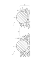
- FIG. 1 is a schematic cross-sectional view showing an example of a functional layer for an electrochemical device according to the present invention.
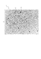
- FIG. 2 is a schematic plan view showing an example of the configuration of the functional layer for an electrochemical device when the surface of the functional layer for an electrochemical device according to the present invention is viewed in a plan view.
- the functional layer for an electrochemical element of the present invention can be used when the members of the electrochemical element are bonded to each other.
- the separator with a functional layer for an electrochemical element of the present invention can be produced by using the functional layer for an electrochemical element of the present invention.
- the electrochemical element of the present invention is at least an electrochemical element including a separator with a functional layer for the electrochemical element of the present invention.
- the functional layer for an electrochemical device of the present invention can be preferably manufactured by using the method for manufacturing a functional layer for an electrochemical device of the present invention.
- the separator with a functional layer for an electrochemical element of the present invention can be preferably produced by using the method for producing a separator with a functional layer for an electrochemical element of the present invention.
- the electrochemical device of the present invention can be preferably manufactured by using the method for manufacturing an electrochemical device of the present invention.
- the functional layer of the present invention contains inorganic particles and a particulate polymer.
- the functional layer of the present invention has a particle dropout portion, and when the surface of the functional layer is viewed in a plan view, the ratio of the area of the particle dropout portion to the total area of the particulate polymer and the particle dropout portion is within a predetermined range. It is characterized in that the volume average particle diameter of the particulate polymer is larger than the thickness of the inorganic particle layer containing the inorganic particles.
- the functional layer of the present invention is excellent in process adhesiveness and can exhibit excellent cycle characteristics in an electrochemical device.
- the functional layer of the present invention formed on a base material such as a separator base material simultaneously has a function as a heat-resistant layer for enhancing the heat resistance of the base material and a function as an adhesive layer for firmly adhering members to each other. It can be suitably used as a single layer to be expressed.
- the functional layer of the present invention may optionally further contain other components other than the above-mentioned inorganic particles and particulate polymer.
- FIG. 1 is a schematic cross-sectional view showing an example of a functional layer for an electrochemical device according to the present invention.
- the functional layer 1 contains the inorganic particles 11 and the particulate polymer 12.
- the inorganic particle layer 13 is formed by overlapping the plurality of inorganic particles 11 in the thickness direction of the functional layer 1.
- the particulate polymer 12 is embedded in the inorganic particle layer 13. That is, a part of the particulate polymer 12 is embedded in the inorganic particle layer 13, and a portion of the particulate polymer 12 that is not embedded in the inorganic particle layer 13 protrudes from the surface of the inorganic particle layer 13.
- the inorganic particles contained in the functional layer are materials that can impart heat resistance to the functional layer.
- the material of the inorganic particles it is preferable that the inorganic particles are stably present in the environment in which the electrochemical element is used and are electrochemically stable.
- preferred materials for inorganic particles include aluminum oxide (alumina), aluminum oxide hydrate (bemite (AlOOH)), gibsite (Al (OH 3 )), silicon oxide, magnesium oxide (magnesia), and water.
- Oxide particles such as magnesium oxide, calcium oxide, titanium oxide (titania), barium titanate (BaTIO 3 ), ZrO, alumina-silica composite oxide; nitride particles such as aluminum nitride and boron nitride; silicon, diamond, etc. Covalently bonded crystal particles; sparingly soluble ion crystal particles such as barium sulfate, calcium fluoride, and barium fluoride; clay fine particles such as talc and montmorillonite; and the like. Among these, aluminum oxide, boehmite, titanium oxide, and barium sulfate are preferable, and aluminum oxide is more preferable. Further, these inorganic particles may be subjected to element substitution, surface treatment, solid solution formation or the like, if necessary. One type of these inorganic particles may be used alone, or two or more types may be used in combination at an arbitrary ratio.
- the volume average particle diameter (D50) of the inorganic particles is preferably 0.1 ⁇ m or more, more preferably 0.2 ⁇ m or more, still more preferably 0.3 ⁇ m or more, preferably 1 ⁇ m or less, more preferably 0.9 ⁇ m. Below, it is more preferably 0.8 ⁇ m or less.
- D50 volume average particle diameter of the inorganic particles
- the inorganic particles are densely packed in the functional layer. Therefore, it is possible to suppress the decrease in ionic conductivity in the functional layer and further improve the electrochemical characteristics (particularly, the output characteristics) of the electrochemical element.
- the functional layer can exhibit excellent heat resistance even when the thickness of the inorganic particle layer is reduced, so that the capacity of the electrochemical element is increased. be able to.
- the volume average particle diameter (D50) of the inorganic particles can be measured by the method described in the examples of the present specification.
- an inorganic particle layer containing inorganic particles is formed.
- the inorganic particle layer is usually formed by overlapping a plurality of inorganic particles in the thickness direction of the functional layer.
- the inorganic particle layer may further contain other components other than the inorganic particles. Examples of other components that can be contained in the inorganic particle layer include other components that will be described later as those that can be contained in the functional layer.
- the thickness of the inorganic particle layer is preferably 0.5 ⁇ m or more, more preferably 0.8 ⁇ m or more, further preferably 1 ⁇ m or more, preferably 6 ⁇ m or less, and more preferably 5 ⁇ m or less. , More preferably 4 ⁇ m or less.
- the thickness of the inorganic particle layer is at least the above lower limit, the heat resistance of the functional layer can be improved.
- the thickness of the inorganic particle layer is not more than the above upper limit, it is possible to suppress a decrease in the energy density of the electrochemical device provided with the functional layer.
- the process adhesiveness of the functional layer can be improved.
- the thickness of the inorganic particle layer can be adjusted by, for example, the content ratio of the inorganic particles in the composition for the functional layer used in the film forming step of the method for producing the functional layer described later, the thickness of the film to be formed, and the like. it can.
- the particulate polymer contained in the functional layer needs to have a volume average particle diameter larger than the thickness of the above-mentioned inorganic particle layer.
- the volume average particle diameter of the particulate polymer in the functional layer is not particularly limited as long as it is in the form of particles.
- the particulate polymer may have a particle shape or any other shape after the members are bonded to each other via the functional layer.
- the particulate polymer may be a crystalline polymer polymer, a non-crystalline polymer polymer, or a mixture thereof.
- the particulate polymer is usually embedded in the above-mentioned inorganic particle layer.
- the particulate polymer in the functional layer preferably has a volume average particle diameter of 1.0 ⁇ m or more, more preferably 2.5 ⁇ m or more, further preferably 5.0 ⁇ m or more, and 10 It is preferably 9.0 ⁇ m or less, more preferably 9.0 ⁇ m or less, and even more preferably 8.0 ⁇ m or less.
- the volume average particle diameter of the particulate polymer in the functional layer is at least the above lower limit
- the particulate polymer is likely to protrude from the inorganic particles on the surface of the functional layer in the thickness direction, so that the functional layer is further excellent.
- Process adhesiveness can be exhibited.
- the member provided with the functional layer and the other member are adhered to each other, a gap is secured between the inorganic particle layer and the other member in the thickness direction of the functional layer. Then, since the electrolytic solution is injected from this gap, the electrolytic solution injection property of the electrochemical element is improved.
- the volume average particle diameter of the particulate polymer in the functional layer is at least the above lower limit, the heat resistance of the functional layer is improved.
- the reason why the heat resistance of the functional layer is improved by setting the volume average particle diameter of the particulate polymer in the functional layer to the above lower limit or more is not clear, but it is presumed as follows. That is, in order to increase the heat resistance, the proportion of inorganic particles in the functional layer needs to be high. Then, it is considered that the heat resistance is improved because the proportion of the inorganic particles in the inorganic particle layer is apparently increased due to the protrusion of the particulate polymer with respect to the inorganic particles on the surface of the functional layer in the thickness direction.
- the volume average particle diameter of the particulate polymer in the functional layer is equal to or less than the above upper limit, the number of particles with respect to the volume of the particulate polymer in the functional layer increases, and the member provided with the functional layer and other members Since the number of bonding points at the time of bonding is increased, the process adhesiveness of the functional layer can be further improved.
- the volume average particle size of the particulate polymer in the functional layer can be adjusted, for example, by the type and amount of the metal hydroxide used when preparing the particulate polymer used for producing the functional layer. .. Details of metal hydroxides will be described later. Further, the volume average particle diameter of the particulate polymer in the functional layer can also be adjusted by, for example, the tension applied to the base material when the base material is conveyed on the roll in the method for producing the functional layer described later. ..
- Ratio of volume average particle size of particulate polymer to thickness of inorganic particle layer is preferably 1.1 or more. It is more preferably 1.2 or more, further preferably 1.6 or more, preferably 10.0 or less, more preferably 5.0 or less, still more preferably 3.5 or less.
- the ratio of the volume average particle diameter of the particulate polymer in the functional layer to the thickness of the inorganic particle layer is equal to or higher than the above lower limit, the particulate polymer easily protrudes from the inorganic particles on the surface of the functional layer in the thickness direction. Therefore, the functional layer can exhibit more excellent process adhesiveness. Further, when the member provided with the functional layer and the other member are adhered to each other, a gap is secured between the inorganic particle layer and the other member in the thickness direction of the functional layer. Then, since the electrolytic solution is injected from this gap, the electrolytic solution injection property of the electrochemical element is improved. Further, when the ratio of the volume average particle diameter of the particulate polymer in the functional layer to the thickness of the inorganic particle layer is at least the above lower limit, the heat resistance of the functional layer is improved.
- the ratio of the volume average particle diameter of the particulate polymer in the functional layer to the thickness of the inorganic particle layer is not more than the above upper limit, the number of particles with respect to the volume of the particulate polymer in the functional layer increases, and the function Since the number of bonding points when the member provided with the layer and the other member are bonded is increased, the process adhesiveness of the functional layer can be further improved.
- the particle size distribution of the particulate polymer in the functional layer is preferably 1.10 or more, more preferably 1.18 or more, preferably 1.50 or less, and more preferably 1.40 or less.
- a functional layer capable of following the expansion and contraction of the electrode, particularly the negative electrode can be formed.
- the particle size distribution of the particulate polymer is equal to or less than the above upper limit, when the members are bonded to each other via the functional layer, the variation in the distance between the members is small, so that the accumulation of gas can be suppressed and the electricity can be suppressed.
- the storage characteristics of chemical elements can be improved.
- the particle size distribution of the particulate polymer in the functional layer can be adjusted by, for example, stirring and classification conditions when the particulate polymer used for producing the functional layer is prepared by the suspension polymerization method. it can. Further, the particle size distribution of the particulate polymer in the functional layer can also be adjusted by, for example, the tension applied to the base material when the base material is conveyed on the roll in the method for producing the functional layer described later.
- the glass transition temperature (Tg) of the particulate polymer is preferably 10 ° C. or higher, more preferably 20 ° C. or higher, further preferably 30 ° C. or higher, preferably 90 ° C. or lower, more preferably 80 ° C. or lower. is there.
- Tg glass transition temperature of particulate polymer
- adjacent members are stuck (blocked) through the functional layer during the storage and transportation of the member including the functional layer and the manufacturing process of the electrochemical element. Can be suppressed. That is, when the glass transition temperature of the particulate polymer is equal to or higher than the above lower limit, the blocking resistance of the functional layer can be enhanced.
- the glass transition temperature of the particulate polymer is not more than the above upper limit, good adhesiveness of the functional layer can be obtained even when the members are pressed and adhered to each other through the functional layer.
- the melting point (Tm) of the particulate polymer is preferably 50 ° C. or higher, more preferably 100 ° C. or higher.
- the melting point of the particulate polymer is at least the above lower limit, good adhesiveness of the functional layer can be ensured even when the particulate polymer contains a crystalline polymer polymer.
- the melting point of the particulate polymer is preferably at least the above lower limit from the viewpoint of further improving the adhesiveness of the functional layer.
- the degree of swelling of the electrolytic solution of the particulate polymer is preferably 1.0 times or more, more preferably 1.2 times or more, still more preferably 1.3 times or more, preferably 15 times or less, more preferably. It is 10 times or less, more preferably 3 times or less.
- the adhesive force of the functional layer in the electrolytic solution can be strengthened.
- the degree of swelling of the electrolytic solution of the particulate polymer when the degree of swelling of the electrolytic solution of the particulate polymer is not more than the above upper limit, the resistance of the functional layer in the electrolytic solution becomes small, so that the electrochemical characteristics of the electrochemical device provided with the functional layer can be improved. .. Further, when the degree of swelling of the electrolytic solution of the particulate polymer is not more than the above upper limit, the injectability of the electrolytic solution of the electrochemical device can be improved.
- the "electrolyte swelling degree" of the particulate polymer can be measured by the method described in the examples of the present specification.
- composition of particulate polymer is not particularly limited as long as the desired effect of the present invention can be obtained. Therefore, as the particulate polymer, for example, a known polymer that can be used as a binder when forming a functional layer can be used.
- the monomer unit constituting the particulate polymer examples include an aromatic vinyl monomer unit, a (meth) acrylic acid ester monomer unit, and a fluorine atom-containing monomer unit.
- the particulate polymer may contain one type of these monomer units alone, or may contain two or more types in an arbitrary ratio.
- (meth) acrylic means acrylic and / or methacrylic.
- containing a monomer unit means that the polymer obtained by using the monomer contains a repeating unit derived from the monomer.
- aromatic vinyl monomer unit When the particulate polymer contains an aromatic vinyl monomer unit, the elasticity of the particulate polymer can be improved and the strength of the functional layer can be increased.
- examples of the aromatic vinyl monomer capable of forming the aromatic vinyl monomer unit are not particularly limited, and for example, styrene, ⁇ -methylstyrene, styrenesulfonic acid, butoxystyrene, vinylnaphthalene, etc. Etc., and among them, styrene is preferable.
- these aromatic vinyl monomers may be used individually by 1 type, and 2 or more types may be used in combination at an arbitrary ratio.
- the content ratio of the aromatic vinyl monomer unit in the particulate polymer is preferably 30% by mass or more, more preferably 30% by mass or more, when all the monomer units in the particulate polymer are 100% by mass. It is 60% by mass or more, preferably 90% by mass or less, and more preferably 85% by mass or less.
- the content ratio of the aromatic vinyl monomer unit is equal to or higher than the above lower limit, the elasticity of the particulate polymer is improved, the strength of the obtained functional layer is ensured, and the adhesion of the functional layer to the substrate is enhanced. Can be done.
- each "content ratio of monomer unit” can be measured by using a nuclear magnetic resonance (NMR) method such as 1 H-NMR.
- (meth) Acrylic acid ester monomers that can form (meth) acrylic acid ester monomer units include methyl acrylate, ethyl acrylate, n-propyl acrylate, isopropyl acrylate, n-butyl acrylate and t-butyl.
- Butyl acrylates such as acrylates, pentyl acrylates, hexyl acrylates, heptyl acrylates, octyl acrylates such as 2-ethylhexyl acrylates, nonyl acrylates, decyl acrylates, lauryl acrylates, n-tetradecyl acrylates, acrylic acid alkyl esters such as stearyl acrylates; and methyl Butyl methacrylates such as methacrylates, ethyl methacrylates, n-propyl methacrylates, isopropyl methacrylates, n-butyl methacrylates and t-butyl methacrylates, octyl methacrylates such as pentyl methacrylates, hexyl methacrylates, heptyl methacrylates and 2-ethylhexyl methacrylates, nonyl methacrylates and decyl methacryl
- Alkyl methacrylates such as lauryl methacrylate, n-tetradecyl methacrylate and stearyl methacrylate. Of these, n-butyl acrylate, 2-ethylhexyl acrylate and methyl methacrylate are preferable, and 2-ethylhexyl acrylate is more preferable.
- these (meth) acrylic acid ester monomers one type may be used alone, or two or more types may be used in combination at an arbitrary ratio.
- the content ratio of the (meth) acrylic acid ester monomer unit in the particulate polymer is preferably 5% by mass or more, more preferably 5% by mass or more, when the total repeating unit of the particulate polymer is 100% by mass. It is 10% by mass or more, preferably 65% by mass or less, and more preferably 60% by mass or less.
- the content ratio of the (meth) acrylic acid ester monomer unit is equal to or higher than the above lower limit, it is possible to avoid an excessive decrease in the glass transition temperature of the particulate polymer and improve the blocking resistance of the obtained functional layer. Can be made to.
- the content ratio of the (meth) acrylic acid ester monomer unit is not more than the above upper limit, the adhesion between the functional layer and the base material can be improved.
- the particulate polymer may contain a crosslinkable monomer unit in addition to the above-mentioned monomer unit.
- the crosslinkable monomer unit is a monomer capable of forming a crosslinked structure during or after polymerization by heating or irradiation with energy rays.
- Examples of the monomer capable of forming a crosslinkable monomer unit include a polyfunctional monomer having two or more polymerization-reactive groups in the monomer.
- Examples of such a polyfunctional monomer include a divinyl compound such as divinylbenzene; a di (meth) acrylic acid ester such as diethylene glycol dimethacrylate, ethylene glycol dimethacrylate, diethylene glycol diacrylate, and 1,3-butylene glycol diacrylate.
- Tri (meth) acrylic acid ester compounds such as trimethylolpropane trimethacrylate and trimethylolpropane triacrylate; ethylenically unsaturated monomers containing epoxy groups such as allylglycidyl ether and glycidyl methacrylate; and the like. Of these, ethylene glycol dimethacrylate is preferable. As these crosslinkable monomers, one type may be used alone, or two or more types may be used in combination at an arbitrary ratio.
- the content ratio of the crosslinkable monomer unit in the particulate polymer is preferably 0.02% by mass or more when the amount of all the monomer units of the particulate polymer is 100% by mass. It is preferably 2% by mass or less, more preferably 1.5% by mass or less, and further preferably 1% by mass or less. When the content ratio of the crosslinkable monomer unit is within the above range, the elution of the particulate polymer into the electrolytic solution can be sufficiently suppressed.
- the particulate polymer may contain other monomer units other than the aromatic vinyl monomer unit, the (meth) acrylic acid ester monomer unit, and the crosslinkable monomer unit.
- the other monomer unit is not particularly limited, and examples thereof include a nitrile group-containing monomer unit and an acid group-containing monomer unit described in the section of "Binder" described later. Be done.
- Nirile group-containing monomer unit As an example of the nitrile group-containing monomer capable of forming the nitrile group-containing monomer unit, ⁇ , ⁇ -ethylenically unsaturated nitrile monomer can be mentioned.
- the ⁇ , ⁇ -ethylenically unsaturated nitrile monomer is not particularly limited as long as it is an ⁇ , ⁇ -ethylenically unsaturated compound having a nitrile group, and for example, acrylonitrile; ⁇ -chloroacrylonitrile, Examples thereof include ⁇ -halogenoacrylonitrile such as ⁇ -bromoacrylonitrile; ⁇ -alkylacrylonitrile such as methacrylonitrile and ⁇ -ethylacrylonitrile; As these nitrile group-containing monomers, one type may be used alone, or two or more types may be used in combination at an arbitrary ratio.
- the content ratio of the nitrile group-containing monomer unit in the particulate polymer is preferably 3% by mass or more, preferably 4% by mass, assuming that all the repeating units in the particulate polymer are 100% by mass. % Or more, more preferably 6% by mass or more, further preferably 30% by mass or less, more preferably 27% by mass or less, and further preferably 25% by mass or less. preferable.
- the content ratio of the nitrile group-containing monomer unit is at least the above lower limit, the binding force of the particulate polymer can be improved and the peel strength of the functional layer can be increased.
- the content ratio of the nitrile group-containing monomer unit is not more than the above upper limit, the flexibility of the particulate polymer can be enhanced.
- the content ratio of the other monomer units in the particulate polymer is preferably 0% by mass or more, preferably 10% by mass or less, more preferably 7% by mass or less, still more preferably 5% by mass or less. Is. When the content ratio of the other monomer units is 10% by mass or less, it is possible to suppress the deterioration of the stability of the composition for the functional layer used for forming the functional layer.
- the particulate polymer may contain a fluorine atom-containing monomer unit.
- the fluorine atom-containing monomer capable of forming the fluorine atom-containing monomer unit are not particularly limited, and for example, vinylidene fluoride, tetrafluoroethylene, hexafluoropropylene, vinyl trifluoride, and fluorine are used. Examples thereof include vinyl chloride and perfluoroalkyl vinyl ether. Of these, vinylidene fluoride is preferable.
- these fluorine atom-containing monomers one type may be used alone, or two or more types may be used in combination at an arbitrary ratio.
- the particulate polymer when the particulate polymer contains a fluorine atom-containing monomer unit, the particulate polymer is fluorinated as a fluorine atom-containing monomer from the viewpoint of ensuring better adhesiveness of the functional layer. It is preferably a fluorine atom-containing polymer using vinylidene.
- a fluorine atom-containing polymer a homopolymer of vinylidene fluoride, a copolymer of vinylidene fluoride and another fluoroamino atom-containing monomer copolymerizable therewith, and vinylidene fluoride and copolymerization thereof. Copolymers of other possible fluorine atom-containing monomers and copolymers with them are preferred.
- PVdF polyvinylidene fluoride
- PTFE polytetrafluoroethylene
- PVdF-HFP vinylidene fluoride-hexafluoropropylene copolymer
- PVdF-HFP vinylidene fluoride-hexafluoropropylene copolymer
- the particulate polymer can be prepared by polymerizing a monomer composition containing the above-mentioned monomer in an aqueous solvent such as water.
- the ratio of each monomer in the monomer composition is usually the same as the ratio of each monomer unit in the particulate polymer.
- the polymerization mode is not particularly limited, and any method such as a suspension polymerization method, an emulsion polymerization agglutination method, or a pulverization method can be used. Among them, the suspension polymerization method and the emulsion polymerization agglutination method are preferable, and the suspension polymerization method is more preferable, from the viewpoint of efficiently preparing the particulate polymer. Further, as the polymerization reaction, any reaction such as radical polymerization or living radical polymerization can be used.
- the monomer composition used when preparing the particulate polymer includes a chain transfer agent, a polymerization modifier, a polymerization reaction delaying agent, a reactive fluidizing agent, a filler, a flame retardant, an antiaging agent, and a coloring agent.
- Other compounding agents such as agents can be blended in any blending amount.
- Preparation of particulate polymer by suspension polymerization method (1) Preparation of monomer composition First, the monomer constituting the desired particulate polymer and other compounding agents added as necessary are mixed to prepare the monomer composition. .. (2) Formation of Droplets Next, the monomer composition is dispersed in water, a polymerization initiator is added, and then droplets of the monomer composition are formed.
- the method for forming the droplets is not particularly limited, and for example, the aqueous medium containing the monomer composition can be formed by shearing and stirring using a disperser such as an emulsification disperser.
- examples of the polymerization initiator used include oil-soluble polymerization initiators such as t-butylperoxy-2-ethylhexanoate and azobisisobutyronitrile.
- the polymerization initiator may be added after the monomer composition is dispersed in water and before forming droplets, or may be added to the monomer composition before being dispersed in water. Good.
- a dispersion stabilizer for example, a metal hydroxide such as magnesium hydroxide, sodium dodecylbenzenesulfonate, or the like can be used.
- the temperature of the water containing the formed droplets is raised to start the polymerization, whereby a particulate polymer is formed in the water.
- the reaction temperature of the polymerization is preferably 50 ° C. or higher and 95 ° C. or lower.
- the reaction time of the polymerization is preferably 1 hour or more and 10 hours or less, preferably 8 hours or less, and more preferably 6 hours or less.
- the particulate polymer can be obtained by washing, filtering and drying the water containing the particulate polymer according to a conventional method.
- the functional layer of the present invention has a particle dropout portion.
- the particle dropout portion is a recess (recess) formed on the surface of the inorganic particle layer. Since the functional layer has the particle dropout portion, the electrolytic solution is accumulated in the particle dropout portion in the electrochemical device, so that the electrolyte solution retention property of the functional layer is enhanced and the electrochemical element can exhibit excellent cycle characteristics. ..
- the particle dropout portion is usually formed by dropping out of the particulate polymer embedded in the inorganic particle layer, but may be formed by dropping out of the inorganic particles constituting the inorganic particle layer.
- FIG. 2 is a schematic plan view showing an example of the configuration of the functional layer for an electrochemical device when the surface of the functional layer for an electrochemical device according to the present invention is viewed in a plan view.
- the functional layer 1 contains an inorganic particle layer 13 containing inorganic particles and a particulate polymer 12.
- the functional layer 1 has a particle dropout portion 14.
- Ratio of the area of the particle dropout to the total area of the particulate polymer and the particle dropout needs to be 0.1% or more, which is 0. It is preferably 5.5% or more, more preferably 1.5% or more, further preferably 5.0% or more, and it is necessary to be 40.0% or less, 30.0. % Or less, more preferably 15.0% or less.
- the cycle characteristics of the electrochemical device can be enhanced by enhancing the electrolyte retention property of the functional layer. it can.
- the ratio of the area of the particle-dropped portion to the total area of the particulate polymer and the particle-dropped portion is not more than the above upper limit, the particulate polymer remains appropriately in the functional layer, so that the process of the functional layer Adhesion can be improved.
- the particulate polymer is sufficiently left in the functional layer, so that the electrochemical element is used.
- the separator can be protected by the particulate polymer in the functional layer. Therefore, since the separator is not excessively crushed, the cycle characteristics of the electrochemical device can be improved. Further, a sufficient amount of the particulate polymer remains in the functional layer, so that a gap is secured between the inorganic particle layer and other members. Then, since the electrolytic solution is injected from this gap, the electrolytic solution injection property of the electrochemical element can be improved.
- the ratio of the area of the particle-dropped portion to the total area of the particulate polymer and the particle-dropped portion is used, for example, in the film forming step of the method for producing the functional layer, which will be described later. It can be adjusted by the volume average particle size and particle size distribution of the particulate polymer in the composition for the functional layer, and the tension applied during the particle dropping step.
- Ratio of total area of particulate polymer and particle dropouts to the unit area of the functional layer is preferably 10% or less, preferably 7% or less. More preferably, it is preferably 1% or more, and more preferably 4% or more.
- the ratio of the total area of the particulate polymer and the particle-dropped portion to the unit area of the functional layer is not more than the above upper limit, the heat resistance of the functional layer can be improved.
- the process adhesiveness of the functional layer can be further improved.
- the ratio of the total area of the particulate polymer and the particle-dropped portion to the unit area of the functional layer is determined, for example, in the film forming step of the method for producing the functional layer, which will be described later. It can be adjusted by the volume average particle diameter of the particulate polymer in the composition for the functional layer to be used, the volume ratio of the inorganic particles to the particulate polymer, and the like.
- the functional layer of the present invention may further contain other components other than the above-mentioned inorganic particles and particulate polymer.
- other components are usually contained in the above-mentioned inorganic particle layer.
- a binder and a water-soluble polymer can be used as the other components.
- the binder which can be arbitrarily contained in the functional layer, is used to prevent components such as particulate polymers contained in the functional layer from falling off from the functional layer.
- composition of the binder is not particularly limited, and is, for example, a known polymer that is water-insoluble and can be dispersed in a dispersion medium such as water, for example, a binder resin such as a thermoplastic elastomer.
- a binder resin such as a thermoplastic elastomer.
- thermoplastic elastomer a conjugated diene polymer and an acrylic polymer are preferable, and an acrylic polymer is more preferable.
- water-insoluble means that when 0.5 g of the polymer is dissolved in 100 g of water at a temperature of 25 ° C., the insoluble content is 90% by mass or more. ..
- the conjugated diene-based polymer refers to a polymer containing a conjugated diene monomer unit.
- Specific examples of the conjugated diene polymer are not particularly limited, and a copolymer containing an aromatic vinyl monomer unit such as a styrene-butadiene copolymer (SBR) and an aliphatic conjugated diene monomer unit. Examples include polymers, butadiene rubber (BR), acrylic rubber (NBR) (copolymers containing acrylonitrile units and butadiene units), and hydrides thereof.
- the acrylic polymer refers to a polymer containing a (meth) acrylic acid ester monomer unit. One type of these binders may be used alone, or two or more types may be used in combination at an arbitrary ratio.
- the acrylic polymer that can be preferably used as the binder is not particularly limited, and for example, the above-mentioned (meth) acrylic acid ester monomer unit, the crosslinkable monomer unit, and the following. Examples thereof include a monomer containing an acid group-containing monomer unit to be described.
- the acid group-containing monomer capable of forming an acid group-containing monomer unit for example, a monomer having a carboxylic acid group, a monomer having a sulfonic acid group, and a single amount having a phosphoric acid group.
- a monomer having a carboxylic acid group for example, a monomer having a sulfonic acid group, and a single amount having a phosphoric acid group.
- examples include the body and a monomer having a hydroxyl group.
- Examples of the monomer having a carboxylic acid group include monocarboxylic acid and dicarboxylic acid.
- Examples of the monocarboxylic acid include acrylic acid, methacrylic acid, crotonic acid and the like.
- Examples of the dicarboxylic acid include maleic acid, fumaric acid, itaconic acid and the like.
- Examples of the monomer having a sulfonic acid group include vinyl sulfonic acid, methyl vinyl sulfonic acid, (meth) allyl sulfonic acid, ethyl (meth) acrylate-2-sulfonate, and 2-acrylamide-2-methyl. Examples thereof include propanesulfonic acid and 3-allyloxy-2-hydroxypropanesulfonic acid.
- (meth) allyl means allyl and / or metharyl
- (meth) acrylic means acrylic and / or methacryl.
- examples of the monomer having a phosphate group include -2- (meth) acryloyloxyethyl phosphate, methyl-2- (meth) acryloyloxyethyl phosphate, and ethyl phosphate- (meth) acryloyloxyethyl. And so on.
- (meth) acryloyl means acryloyl and / or methacryloyl.
- Examples of the monomer having a hydroxyl group include -2-hydroxyethyl acrylate, -2-hydroxypropyl acrylate, -2-hydroxyethyl methacrylate, and -2-hydroxypropyl methacrylate.
- these acid group-containing monomers one kind may be used alone, and two or more kinds may be used in combination at an arbitrary ratio.
- the ratio of the (meth) acrylic acid ester monomer unit in the acrylic polymer is preferably 50% by mass or more, more preferably 55% by mass or more, still more preferably 58% by mass or more, and preferably 98% by mass. % Or less, more preferably 97% by mass or less, still more preferably 96% by mass or less.
- the proportion of the crosslinkable monomer unit in the acrylic polymer is preferably 0.1% by mass or more, more preferably 1.0% by mass or more, and preferably 3.0% by mass or less, more preferably 3.0% by mass or less. It is 2.5% by mass or less.
- the ratio of the acid group-containing monomer unit in the acrylic polymer is preferably 0.1% by mass or more, more preferably 0.3% by mass or more, still more preferably 0.5% by mass or more, and is preferable. Is 20% by mass or less, more preferably 10% by mass or less, still more preferably 5% by mass or less.
- the acrylic polymer may contain other monomer units.
- monomers that can form other monomer units that can be contained in the acrylic polymer 1,3-butadiene, 2-methyl-1,3-butadiene, 2,3-dimethyl- Fat group conjugated diene monomer such as 1,3-butadiene, 2-chlor-1,3-butadiene; aromatic vinyl monomer and nitrile group-containing single amount described in the section "Composition of particulate polymer".
- olefin monomers such as ethylene and propylene; halogen atom-containing monomers such as vinyl chloride and vinylidene chloride; vinyl ester monomers such as vinyl acetate, vinyl propionate, vinyl butyrate and vinyl benzoate; methyl vinyl ether, Vinyl ether monomers such as ethyl vinyl ether and butyl vinyl ether; vinyl ketone monomers such as methyl vinyl ketone, ethyl vinyl ketone, butyl vinyl ketone, hexyl vinyl ketone and isopropenyl vinyl ketone; and N-vinylpyrrolidone, vinylpyridine and vinyl. Examples thereof include a heterocyclic-containing vinyl compound monomer such as imidazole.
- acrylonitrile is preferable as the other monomer.
- these other monomers one type may be used alone, or two or more types may be used in combination at an arbitrary ratio. Further, the content ratio of other monomer units in the acrylic polymer may be appropriately adjusted.
- the structure of the binder in the functional layer is not particularly limited, but is usually non-particle-like.
- the structure of the binder in the composition for the functional layer used in the method for producing the functional layer described later may be the same as or different from the structure of the binder in the functional layer.
- the structure of the binder in the composition for the functional layer may be in the form of particles or may be in the form of non-particles.
- the glass transition temperature (Tg) of the binder is preferably ⁇ 100 ° C. or higher, more preferably ⁇ 90 ° C. or higher, further preferably ⁇ 80 ° C. or higher, and less than 30 ° C. It is preferably 20 ° C or lower, more preferably 15 ° C or lower.
- Tg glass transition temperature of binder
- the adhesiveness and strength of the binder can be enhanced.
- the glass transition temperature of the binder is less than the above upper limit or less than the above upper limit, the flexibility of the functional layer can be further enhanced.
- the content of the binder in the functional layer is preferably 0.1 part by mass or more, more preferably 0.2 part by mass or more, and further preferably 0.5 part by mass or more per 100 parts by mass of the inorganic particles. Yes, preferably 20 parts by mass or less, more preferably 15 parts by mass or less, still more preferably 10 parts by mass or less.
- the content of the binder is at least the above lower limit, it is possible to sufficiently prevent the particulate polymer from falling off from the functional layer and sufficiently increase the peel strength of the functional layer.
- the content of the binder is not more than the above upper limit, it is possible to suppress the decrease in the ionic conductivity of the functional layer and the decrease in the electrochemical characteristics of the electrochemical element.
- the binder is not particularly limited, and can be prepared, for example, by polymerizing the above-mentioned monomer-containing monomer composition in an aqueous solvent such as water.
- the ratio of each monomer in the monomer composition is usually the same as the ratio of each monomer unit in the binder.
- the polymerization method and the polymerization reaction are not particularly limited, and for example, the polymerization method and the polymerization reaction mentioned in the above-mentioned polymerization method of the particulate polymer can be used.
- the water-soluble polymer that can be optionally contained in the functional layer is a water-soluble polymer used for satisfactorily dispersing components such as inorganic particles and particulate polymer in the functional layer.
- the functional layer contains a water-soluble polymer, components such as inorganic particles and particulate polymer are satisfactorily dispersed, so that heat resistance is improved and even better process adhesiveness can be exhibited.
- water-soluble means that when 0.5 g of the polymer is dissolved in 100 g of water at a temperature of 25 ° C., the insoluble content is less than 1.0% by mass.
- polyacrylic acid As the water-soluble polymer that can be contained in the functional layer, it is preferable to use polyacrylic acid from the viewpoint of better dispersing the inorganic particles and the particulate polymer in the functional layer.
- the content of the water-soluble polymer in the functional layer is preferably 0.1 part by mass or more, more preferably 0.2 part by mass or more, and further preferably 0.3 part by mass or more per 100 parts by mass of the inorganic particles. It is preferably 1 part by mass or less, more preferably 0.9 part by mass or less, and further preferably 0.8 part by mass or less.
- the content of the water-soluble polymer is equal to or higher than the above lower limit, the heat resistance of the functional layer can be further improved by more satisfactorily dispersing the inorganic particles and the particulate polymer in the functional layer, and the process of the functional layer can be further improved. Adhesion can be further improved.
- the content of the water-soluble polymer is not more than the above upper limit, it is possible to suppress the decrease in the ionic conductivity of the functional layer and the decrease in the electrochemical characteristics of the electrochemical device.
- the functional layer of the present invention may further contain additives other than the binder and the water-soluble polymer as other components.
- Additives that can be optionally contained in the functional layer include thickeners and dispersants.
- the thickener for example, carboxymethyl cellulose or the like can be used.
- the dispersant for example, sodium dodecylbenzenesulfonate or the like can be used. The amount of these additives used in the functional layer can be appropriately set within a range in which the desired effect of the present invention can be obtained.
- the method for producing a functional layer for an electrochemical element of the present invention includes a step of forming a film of a composition for an electrochemical element functional layer containing inorganic particles and a particulate polymer on a substrate (film forming step) and a film. It is characterized by including a step of forming a pre-functional layer (drying step) and a step of applying a tension within a predetermined range to the base material on which the pre-functional layer is formed (particle dropout step). And.
- the method for producing a functional layer for an electrochemical element of the present invention it is possible to produce a functional layer for an electrochemical element which is excellent in process adhesiveness and can exhibit excellent cycle characteristics in an electrochemical element.
- the method for producing the functional layer for an electrochemical element of the present invention may include other steps other than the above-mentioned film forming step, drying step, and particle dropping step.
- the above-mentioned functional layer for an electrochemical element of the present invention can be produced. That is, according to the method for producing a functional layer for an electrochemical element of the present invention, it contains inorganic particles and a particulate polymer, has a particle-dropped portion, and when viewed in a plan view, the particulate polymer and the particle-dropped portion.
- a functional layer is produced in which the ratio of the area of the particle dropout portion to the total area of the above is within the above-mentioned predetermined range, and the volume average particle diameter of the particulate polymer is larger than the thickness of the inorganic particle layer containing the inorganic particles. be able to.
- the functional layer for an electrochemical element of the present invention can also be produced by a method other than the method for producing a functional layer for an electrochemical element of the present invention.
- a film of the composition for the functional layer is formed on the substrate.
- composition for functional layer contains at least inorganic particles and a particulate polymer.
- the composition for the functional layer usually contains inorganic particles, a particulate polymer, water as a dispersion medium, and other components that are optionally used.
- Inorganic particles As the inorganic particles contained in the composition for the functional layer, the inorganic particles described above in the section "Functional layer for electrochemical device" can be used.
- the glass transition temperature, melting point and electrolytic solution swelling degree of the particulate polymer contained in the composition for the functional layer are the glass transition temperature, melting point and electrolysis of the particulate polymer described above in the section of "Functional layer for electrochemical element". It can be in the same range as the liquid swelling degree. Further, the composition of the particulate polymer contained in the composition for the functional layer can be the same as the composition of the particulate polymer described above in the section of "functional layer for electrochemical device".
- the volume average particle size of the particulate polymer contained in the composition for the functional layer is preferably 1.0 ⁇ m or more, more preferably 2.5 ⁇ m or more, and more preferably 5.0 ⁇ m or more. It is more preferably 10.0 ⁇ m or less, more preferably 9.0 ⁇ m or less, and further preferably 8.0 ⁇ m or less.
- the volume average particle diameter of the particulate polymer in the composition for the functional layer is equal to or greater than the above lower limit, the particulate polymer tends to protrude with respect to the inorganic particles on the surface of the produced functional layer in the thickness direction. It is possible to make the functional layer exhibit even better process adhesiveness. Further, when the member including the manufactured functional layer and the other member are adhered to each other, a gap is secured between the inorganic particle layer and the other member in the thickness direction of the functional layer. Then, since the electrolytic solution is injected from this gap, the electrolytic solution injection property of the electrochemical element is improved. Further, when the volume average particle diameter of the particulate polymer in the functional composition is at least the above lower limit, the heat resistance of the produced functional layer is improved.
- the volume average particle diameter of the particulate polymer in the composition for the functional layer is equal to or more than the above lower limit, the particulate polymer appropriately drops off in the particle dropping step described later, and the particles fall off to the inorganic particle layer. Since the portions are formed, the electrolyte retention property of the produced functional layer is further enhanced, and the electrochemical element can exhibit more excellent cycle characteristics.
- the volume average particle size of the particulate polymer in the composition for the functional layer is not more than the above upper limit, the particulate polymer is excessively contained in the particle dropping step described later, for example, when the separator is conveyed on the roll. Since it does not fall off, the particulate polymer can be sufficiently left in the produced functional layer. Therefore, the process adhesiveness of the manufactured functional layer for an electrochemical device can be further enhanced.
- the separator can be protected by the particulate polymer remaining in the functional layer during pressing during the manufacture of the electrochemical element. Therefore, since the separator is not excessively crushed, the cycle characteristics of the electrochemical device can be improved.
- the volume average particle diameter of the particulate polymer in the composition for the functional layer is equal to or less than the above upper limit, the number of particles with respect to the volume of the particulate polymer in the produced functional layer is large, and the functional layer is provided. Since the number of bonding points when the member and other members are bonded is increased, the process adhesiveness of the functional layer can be further improved.
- the volume average particle size of the particulate polymer in the composition for the functional layer can be adjusted by the type and amount of the metal hydroxide used when preparing the particulate polymer.
- the particle size distribution of the particulate polymer in the composition for the functional layer is preferably 1.10 or more, more preferably 1.20 or more, preferably 1.50 or less, and more preferably 1.40 or less. Is.
- the particle size distribution of the particulate polymer in the composition for the functional layer is equal to or higher than the above lower limit, the particle size of the particulate polymer varies appropriately, so that the particulate polymer having a large particle size falls off. A particle dropout portion is appropriately formed. Therefore, the electrolyte retention property of the manufactured functional layer is improved, and the cycle characteristics of the electrochemical device can be further improved. Further, when the particle size distribution of the particulate polymer is equal to or higher than the above lower limit, a functional layer capable of following the expansion and contraction of the electrode, particularly the negative electrode, can be formed.
- the particle size distribution of the particulate polymer in the composition for the functional layer is equal to or less than the above upper limit, the variation in the particle size of the particulate polymer is small, and in the particle dropping step described later, for example, on a roll. Since there are few particulate polymers having a large particle size that can be removed during separator transportation, the particulate polymer can be sufficiently left in the produced functional layer. Therefore, the process adhesiveness of the manufactured functional layer for an electrochemical device can be further enhanced. In addition, the separator can be protected by the particulate polymer remaining in the functional layer during pressing during the manufacture of the electrochemical element. Therefore, since the separator is not excessively crushed, the cycle characteristics of the electrochemical device can be improved.
- the particulate polymer remains in the produced functional layer, so that a gap is secured between the inorganic particle layer and other members. Then, since the electrolytic solution is injected from this gap, the electrolytic solution injection property of the electrochemical element can be improved. Further, if the particle size distribution of the particulate polymer in the composition for the functional layer is equal to or less than the above upper limit, the variation in the distance between the members is small when the members are bonded to each other via the manufactured functional layer. , Gas accumulation can be suppressed, and the storage characteristics of the electrochemical element can be improved.
- the particle size distribution of the particulate polymer in the composition for the functional layer can be adjusted by, for example, the conditions of stirring and classification when the particulate polymer is prepared by the suspension polymerization method.
- the values of the volume average particle size and the particle size distribution of the particulate polymer in the composition for the functional layer are the values of the volume average particle size and the particle size distribution of the particulate polymer in the produced functional layer. May be different. This is because, among the particulate polymers contained in the composition for the functional layer, those having a larger particle size are more likely to be shed during the separator transport during the particle shedding step described later, and as a result, remain in the functional layer. It is considered that the values of the volume average particle size and the particle size distribution of the particulate polymer are small.
- the particulate polymer contained in the composition for the functional layer can be prepared by the same method as the method for preparing the particulate polymer described above in the section “Functional layer for electrochemical device”.
- the volume ratio of the inorganic particles to the particulate polymer (inorganic particles / particulate polymer) in the composition for the functional layer is preferably 55/45 or more, and more preferably 60/40 or more. It is preferably 65/35 or more, more preferably 95/5 or less, more preferably 80/20 or less, further preferably 75/25 or less, and 70/30 or less. It is particularly preferable to have.
- the volume ratio of the inorganic particles to the particulate polymer in the composition for the functional layer is at least the above lower limit, the heat resistance of the produced functional layer can be improved.
- the volume ratio of the inorganic particles to the particulate polymer in the composition for the functional layer is not more than the above upper limit, the process adhesiveness of the produced functional layer can be further enhanced.
- the mass ratio of the inorganic particles to the particulate polymer (inorganic particles / particulate polymer) in the composition for the functional layer is preferably 49/51 or more, and more preferably 58/42 or more. It is preferably 64/36 or more, more preferably 99/1 or less, more preferably 94/6 or less, and further preferably 91/9 or less.
- the mass ratio of the inorganic particles to the particulate polymer in the composition for the functional layer is at least the above lower limit, the heat resistance of the produced functional layer can be improved.
- the mass ratio of the inorganic particles to the particulate polymer in the composition for the functional layer is not more than the above upper limit, the process adhesiveness of the produced functional layer can be further enhanced.
- the method for preparing the composition for the functional layer is not particularly limited, and for example, the above-mentioned inorganic particles, the particulate polymer, water as a dispersion medium, and other components used as necessary ( It can be prepared by mixing with a binder and a water-soluble polymer, etc.).
- the particulate polymer or binder is prepared by polymerizing the monomer composition in an aqueous solvent, the particulate polymer or binder remains as it is in the state of an aqueous dispersion. May be mixed with.
- water in the aqueous dispersion may be used as a dispersion medium.
- the mixing method of the above-mentioned components is not particularly limited, but it is preferable to perform mixing using a disperser as a mixing device in order to efficiently disperse each component.
- the disperser is preferably a device capable of uniformly dispersing and mixing the above components. Examples of the disperser include a ball mill, a sand mill, a pigment disperser, a grinder, an ultrasonic disperser, a homogenizer, and a planetary mixer.
- the base material used in the film forming step is not particularly limited, but it is preferable to use a separator base material.
- a release base material other than the separator base material can also be used.
- a release base material it is necessary to transfer the functional layer formed on the release base material to the separator base material after the particle dropping step described later.
- a separator base material is used as the base material, the above-mentioned transfer work becomes unnecessary, so that a separator with a functional layer can be efficiently manufactured.
- the separator base material will be described in detail later.
- the base material used in the method for producing a functional layer of the present invention may have elasticity.
- the method for forming the coating film of the above-mentioned functional layer composition on the base material is not particularly limited, and the functional layer composition may be applied to the surface of the base material, or the functional layer composition may be applied.
- the base material may be immersed in an object. Since it is easy to control the thickness of the produced functional layer (inorganic particle layer), it is preferable to apply the functional layer composition to the surface of the base material.
- the method of applying the composition for the functional layer to the surface of the base material is not particularly limited, and for example, the doctor blade method, the reverse roll method, the direct roll method, the gravure coating method, the bar coating method, the extrusion method, and the brush coating method. Methods such as law can be mentioned.
- a film of the composition for the functional layer may be formed on only one surface of the base material, or a film of the composition for the functional layer may be formed on both sides of the base material. And.
- the coating film of the above-mentioned functional layer composition is dried to form a pre-functional layer.
- the method for drying the coating film of the composition for the functional layer is not particularly limited, and a known method can be used. For example, drying by warm air, hot air, low humidity air, vacuum drying, drying by irradiation with infrared rays or electron beams, etc. The law can be mentioned.
- the drying conditions are not particularly limited, but the drying temperature is preferably 50 to 150 ° C., and the drying time is preferably 1 to 30 minutes.
- the formed pre-functional layer contains at least inorganic particles and a particulate polymer. Then, an inorganic particle layer containing inorganic particles is formed in the pre-functional layer.
- the inorganic particle layer is usually formed by overlapping a plurality of inorganic particles in the thickness direction of the functional layer. Then, it is assumed that the particulate polymer is usually embedded in the inorganic particle layer.
- ⁇ Particle dropout process> In the particle shedding step, a tension within a predetermined range is applied to the base material on which the above-mentioned pre-functional layer is formed. Thereby, the functional layer formed on the base material can be obtained.
- a tension within a predetermined range is applied to the base material on which the above-mentioned pre-functional layer is formed.
- the functional layer formed on the base material can be obtained.
- a part of the particulate polymer embedded in the inorganic particle layer in the pre-functional layer is shed to form a particle-dropped portion. be able to.
- the tension applied to the base material on which the pre-functional layer is formed is assumed to be the in-plane tension of the base material.
- tension can be applied in the longitudinal direction of the base material on which the pre-functional layer is formed.
- tension applied against the pre-function layer is formed substrate is required to be 1N / mm 2 or more, preferably 1.5 N / mm 2 or more, 2N / mm 2 or more more preferably, further preferably 2.5 N / mm 2 or more, more preferably at 4N / mm 2 or more, must be at 20 N / mm 2 or less, 16N / mm 2 preferably less, more preferably 12N / mm 2 or less, still more preferably 8N / mm 2 or less, and still more preferably 7N / mm 2 or less.
- the particulate polymer When the tension applied to the base material on which the pre-functional layer is formed is equal to or higher than the above lower limit, the particulate polymer can be shed from the inorganic particle layer to sufficiently form the particle-dropped portion, so that the functional layer to be produced is produced. It is possible to enhance the electrolyte retention of the electrolytic solution and to make the electrochemical element exhibit excellent cycle characteristics. Further, if the tension applied to the base material on which the pre-functional layer is formed is equal to or higher than the above lower limit, the particulate polymer having an extremely large particle size is dropped off and remains in the produced functional layer. It is possible to reduce the variation in the particle size of the particulate polymer. Therefore, when the members are bonded to each other via the functional layer, the variation in the distance between the members is small, so that the accumulation of gas can be suppressed and the storage characteristics of the electrochemical element can be improved.
- the tension applied to the base material on which the pre-functional layer is formed is not more than the above upper limit, the particulate polymer does not excessively fall off from the inorganic particle layer, so that the particulate polymer is contained in the produced functional layer. Can be moderately retained. Therefore, the process adhesiveness of the manufactured functional layer for an electrochemical device can be enhanced.
- the separator can be protected by the particulate polymer remaining in the functional layer during pressing during the manufacture of the electrochemical element. Therefore, since the separator is not excessively crushed, the cycle characteristics of the electrochemical device can be improved. Further, a sufficient amount of the particulate polymer remains in the produced functional layer, so that a gap is secured between the inorganic particle layer and other members. Then, since the electrolytic solution is injected from this gap, the electrolytic solution injection property of the electrochemical element can be improved.
- the above-mentioned film forming step, drying step, and particle dropping step can be continuously carried out while transporting the base material by a roll-to-roll method. .. Specifically, first, the base material wound around the base material roll is unwound, and the functional layer composition is applied to the surface of the base material by a coating method such as a gravure coating method to obtain the functional layer composition. (Film formation step). Next, the coating film is dried to form a pre-functional layer while transporting the base material on which the coating film is formed (drying step). Then, the obtained base material on which the pre-functional layer is formed is conveyed, wound around a recovery roll, and recovered in a roll shape.
- a coating method such as a gravure coating method
- the method for manufacturing a functional layer is carried out by the roll-to-roll method
- tension is applied to the base material in order to convey the base material.
- a tension within the predetermined range described above is applied to the base material on which the pre-functional layer is formed.
- a part of the particulate polymer embedded in the inorganic particle layer in the pre-functional layer can be shed to form a particle shedding portion. Therefore, the above-mentioned transfer can be carried out as a particle dropping step.
- the base material on which the functional layer is formed can be recovered on the recovery roll. Further, in the above-mentioned transfer, the base material may be conveyed on a roll such as a transfer roll.
- the pre-functional layer formed on the base material When the base material is transported on the roll, the pre-functional layer formed on the base material may come into contact with the transport roll during transport, or is bent together with the base material along the shape of the transport roll. Also good. Then, when the pre-functional layer formed on the base material comes into contact with the transport roll and / or is bent along the shape of the transport roll while applying tension within the predetermined range described above, the pre-functional layer is pre-formed. A part of the particulate polymer embedded in the inorganic particle layer in the functional layer may be shed to form a particle shedding portion.
- the volume average particle diameter of the particulate polymer is larger than the thickness of the inorganic particle layer containing the inorganic particles.
- the functional layer can exhibit excellent process adhesiveness.
- the volume average particle diameter of the particulate polymer in the functional layer and the thickness of the inorganic particle layer are appropriately adjusted so that the volume average particle diameter of the particulate polymer in the functional layer becomes larger than the thickness of the inorganic particle layer. It should be possible.
- the volume average particle diameter of the particulate polymer and the thickness of the inorganic particle layer in the functional layer can be adjusted by the methods described above in the section “Functional layer for electrochemical element”, respectively.
- the functional layer is formed by performing the above-mentioned film forming step, drying step, and particle dropping step on one surface (surface) of the base material.
- the functional layer may be further formed on the other surface (back surface) of the base material by performing a film forming step, a drying step, and a particle dropping step.
- the conditions of the above steps performed on the front surface of the base material and the conditions of the above steps performed on the back surface of the base material may be the same or different. And.
- the separator with a functional layer for an electrochemical element of the present invention (hereinafter, also simply referred to as "separator with a functional layer”) is characterized in that the above-mentioned functional layer for an electrochemical element of the present invention is provided on a separator base material. To do. Therefore, the separator with a functional layer of the present invention has a functional layer that is excellent in process adhesiveness and can exhibit excellent cycle characteristics in an electrochemical device.
- the separator with a functional layer of the present invention may be provided with the functional layer of the present invention on only one surface of the separator base material, or may be provided with the functional layer of the present invention on both surfaces of the separator base material. May be good. Further, the separator with a functional layer of the present invention may include a functional layer other than the functional layer of the present invention.
- the separator base material is not particularly limited, and for example, those described in JP-A-2012-204303 can be used. Among these, from the viewpoint that the film thickness of the entire separator with a functional layer can be reduced, thereby increasing the ratio of the electrode active material in the electrochemical element and increasing the capacity per volume.
- a microporous film made of a polyolefin-based resin (polyethylene, polypropylene, polybutene, polyvinyl chloride) is preferable.
- the method for producing a separator with a functional layer for an electrochemical element of the present invention is characterized in that the functional layer for an electrochemical element is formed on a separator base material by using the above-described method for producing a functional layer for an electrochemical element of the present invention. And. According to the method for producing a separator with a functional layer of the present invention, it is possible to produce a separator having a functional layer having excellent process adhesiveness and capable of exhibiting excellent cycle characteristics in an electrochemical device. Then, according to the method for producing a separator with a functional layer of the present invention, the above-mentioned separator with a functional layer of the present invention can be produced.
- the separator with a functional layer produced by the method for producing a separator with a functional layer of the present invention can be produced in a shorter man-hour and time than a base material having a heat-resistant layer and an adhesive layer separately. Therefore, productivity is high.
- the method for producing a separator with a functional layer of the present invention can be carried out, for example, by using a separator base material as a base material in the above-mentioned method for producing a functional layer of the present invention.
- a separator base material used in the method for producing a separator with a functional layer of the present invention
- the separator base material described above in the section "Separator with a functional layer for an electrochemical device" can be used.
- the electrochemical device of the present invention is characterized by including the above-mentioned separator with a functional layer for the electrochemical device of the present invention. Since the electrochemical device of the present invention includes the above-mentioned separator with a functional layer for the electrochemical device of the present invention, excellent cycle characteristics can be exhibited.
- the electrochemical element of the present invention is not particularly limited, and is, for example, a lithium ion secondary battery or an electric double layer capacitor, preferably a lithium ion secondary battery.
- the lithium ion secondary battery according to the present invention includes the above-mentioned separator with a functional layer of the present invention. More specifically, the lithium ion secondary battery includes a positive electrode, a negative electrode, a separator with a functional layer of the present invention, and an electrolytic solution.
- the positive electrode and the separator base material and / or the negative electrode and the separator base material are firmly adhered to each other in the electrolytic solution by the functional layer provided in the separator. Therefore, the increase in the distance between the electrode plates due to repeated charging and discharging is suppressed, and the battery characteristics such as the cycle characteristics are good. Further, in this lithium ion secondary battery, the heat resistance of the separator base material is improved by the functional layer provided in the separator. Further, in the lithium ion secondary battery according to the present invention, the particle dropout portion is formed in the functional layer provided in the separator, and the electrolytic solution can be held well, so that the cycle characteristics are good.
- positive electrode negative electrode and electrolytic solution
- known positive electrode, negative electrode and electrolytic solution used in the lithium ion secondary battery can be used.
- Electrodes positive electrode and negative electrode
- an electrode formed by forming an electrode mixture layer on a current collector can be used.
- a metal material such as iron, copper, aluminum, nickel, stainless steel, titanium, tantalum, gold, and platinum can be used.
- the current collector for the positive electrode it is preferable to use a current collector made of aluminum.
- the electrode mixture layer a layer containing an electrode active material and a binder can be used as the electrode mixture layer.
- an organic electrolytic solution in which a supporting electrolyte is dissolved in an organic solvent is usually used.
- a lithium salt is used in a lithium ion secondary battery.
- lithium salts include LiPF 6 , LiAsF 6 , LiBF 4 , LiSbF 6 , LiAlCl 4 , LiClO 4 , CF 3 SO 3 Li, C 4 F 9 SO 3 Li, CF 3 COOLi, (CF 3 CO) 2 NLi. , (CF 3 SO 2 ) 2 NLi, (C 2 F 5 SO 2 ) NLi and the like.
- LiPF 6 , LiClO 4 , and CF 3 SO 3 Li are preferable because they are easily soluble in a solvent and show a high degree of dissociation.
- One type of electrolyte may be used alone, or two or more types may be used in combination. Normally, the more the supporting electrolyte with a higher degree of dissociation is used, the higher the lithium ion conductivity tends to be. Therefore, the lithium ion conductivity can be adjusted depending on the type of the supporting electrolyte.
- the organic solvent used in the electrolytic solution is not particularly limited as long as it can dissolve the supporting electrolyte.
- a mixed solution of these solvents may be used.
- carbonates are preferable because they have a high dielectric constant and a wide stable potential region.
- the lower the viscosity of the solvent used the higher the lithium ion conductivity tends to be. Therefore, the lithium ion conductivity can be adjusted depending on the type of solvent.
- the concentration of the electrolyte in the electrolytic solution can be adjusted as appropriate. Further, a known additive may be added to the electrolytic solution.
- the method for manufacturing an electrochemical element of the present invention is characterized by using the separator with a functional layer for an electrochemical element obtained by the above-described method for manufacturing a separator with a functional layer for an electrochemical element of the present invention. According to the method for manufacturing an electrochemical device of the present invention, it is possible to manufacture an electrochemical device capable of exhibiting excellent cycle characteristics. Then, according to the method for producing an electrochemical element of the present invention, the above-mentioned electrochemical element of the present invention can be produced.
- the time required for manufacturing a separator is shortened and is higher than that in the case of manufacturing and using a separator having a heat-resistant layer and an adhesive layer separately.
- the electrochemical element can be manufactured with productivity.
- a lithium ion secondary battery is manufactured by the method for manufacturing an electrochemical element of the present invention, for example, it is necessary to superimpose the positive electrode and the negative electrode described above in the section of "electrochemical element" via a separator with a functional layer.
- a lithium ion secondary battery can be manufactured by rolling, folding, or the like into a battery container, injecting an electrolytic solution into the battery container, and sealing the battery container. Then, as the separator with a functional layer, the separator with a functional layer obtained by the above-described method for producing a separator with a functional layer of the present invention is used.
- an expanded metal, a fuse, an overcurrent prevention element such as a PTC element, a lead plate, or the like may be placed in the battery container to prevent the pressure inside the battery from rising and overcharging / discharging.
- the shape of the battery may be, for example, a coin type, a button type, a sheet type, a cylindrical type, a square type, a flat type, or the like.
- the ratio to the thickness of the layer and the volume ratio and mass ratio of the inorganic particles to the particulate polymer were measured by the following methods.
- the process adhesiveness of the functional layer, the heat resistance of the functional layer, the electrolyte injection property of the secondary battery, the cycle characteristics of the secondary battery, and the storage characteristics of the secondary battery were evaluated by the following methods.
- ⁇ Glass transition temperature of particulate polymer and binder The particulate polymer and binder prepared in Examples and Comparative Examples were used as measurement samples. Weigh 10 mg of the measurement sample into an aluminum pan, and use an empty aluminum pan as a reference with a differential thermal analysis measuring device (“EXSTAR DSC6220” manufactured by SII Nanotechnology), and measure the temperature range from -100 ° C to 500 ° C. Measurements were performed at a heating rate of 10 ° C./min under the conditions specified in JIS Z 8703 to obtain a differential scanning calorimetry (DSC) curve.
- EXSTAR DSC6220 manufactured by SII Nanotechnology
- the baseline immediately before the endothermic peak of the DSC curve whose differential signal (DDSC) becomes 0.05 mW / min / mg or more and the tangent of the DSC curve at the inflection point that first appears after the endothermic peak.
- the intersection with was determined as the glass transition temperature (° C.).
- the melting point (Tm) of the particulate polymer prepared in Example 13 was measured as follows. First, the particulate polymer was melted by heating, and the melted polymer was rapidly cooled with dry ice, whereby an amorphous polymer was obtained. Subsequently, using an amorphous polymer as a test piece, the melting point (Tm) was measured at a heating rate of 10 ° C./min (heating mode) using a differential scanning calorimeter (DSC). ..
- ⁇ Volume average particle size and particle size distribution of the particulate polymer in the composition for the functional layer The dried particulate polymer prepared in Examples and Comparative Examples was used as a measurement sample. An amount equivalent to 0.1 g of the measurement sample was weighed, placed in a beaker, and 0.1 mL of an aqueous alkylbenzene sulfonic acid solution (manufactured by Fujifilm, "Drywell") was added as a dispersant. Further, 10 to 30 mL of a diluent (“Isoton II” manufactured by Beckman Coulter) was added to the above beaker, and the mixture was dispersed in a 20 W (Watt) ultrasonic disperser for 3 minutes.
- a diluent (“Isoton II” manufactured by Beckman Coulter) was added to the above beaker, and the mixture was dispersed in a 20 W (Watt) ultrasonic disperser for 3 minutes.
- the particle size (Dv) was determined and used as the volume average particle size of the particulate polymer in the composition for the functional layer.
- the number average particle size (Dn) of the measurement sample was also measured, and the value of the particle size distribution (Dv / Dn) of the particulate polymer in the composition for the functional layer was calculated.
- volume average particle size of binder The volume average particle diameter of the binder prepared in the examples was measured by a laser diffraction method. Specifically, an aqueous dispersion solution containing the prepared binder (adjusted to a solid content concentration of 0.1% by mass) was used as a sample. Then, in the particle size distribution (volume basis) measured using a laser diffraction type particle size distribution measuring device (“LS-230” manufactured by Beckman Coulter, Inc.), the cumulative volume calculated from the small diameter side is 50%. The particle size D50 was defined as the volume average particle size.
- ⁇ Volume average particle size of inorganic particles> In the particle size distribution (volume basis) measured by the laser diffraction method, the particle size (D50) at which the cumulative volume calculated from the small diameter side is 50% was defined as the volume average particle size of the inorganic particles.
- ⁇ Degree of swelling of electrolyte> The aqueous dispersion containing the particulate polymer prepared in Examples and Comparative Examples was placed in a petri dish made of polytetrafluoroethylene and dried at 25 ° C. for 48 hours to prepare a powder. About 0.2 g of the obtained powder was pressed at 200 ° C. and 5 MPa for 2 minutes to obtain a film. Then, the obtained film was cut into 1 cm squares to obtain a test piece. The mass W0 of this test piece was measured. Further, the above-mentioned test piece was immersed in an electrolytic solution at 60 ° C. for 72 hours.
- EC ethylene carbonate
- DEC diethyl carbonate
- VC vinylene carbonate
- LiPF 6 dissolved at a concentration of 1 mol / L was used.
- the surface of the functional layer of the separator with a functional layer produced in Examples and Comparative Examples was subjected to a field emission scanning electron microscope (FE-SEM, JEOL Ltd., "JSM-7800 Prime", detector: BED-C, Using an acceleration voltage (5 kV, magnification: 5000 to 10000 times), each particulate polymer was magnified and observed. The number of observed particulate polymers was 200. The observed image of the particulate polymer was binarized to determine the area of the particulate polymer in the field of view.
- the emphasis conditions are set to "brightness: -30” and “contrast: +70", and the filter is set to 7x7.
- Two threshold values were set, and binarization (threshold value 38) was performed.
- the surface of the functional layer was viewed in a plan view for each of the 200 obtained SEM images, and the area of the particulate polymer was determined.
- the diameter of the particulate polymer was calculated from the area of the obtained particulate polymer, assuming that the particulate polymer was a perfect sphere. From the diameter of 200 particulate polymers, the volume was calculated assuming that the particulate polymer was a perfect sphere.
- the total value of the volumes of all the particulate polymers is 100%, the amount of the particulate polymers present in each particle size section is indicated by%, and the particle size is 50% of the amount of the particulate polymers.
- the volume average particle diameter (Dv) of the particulate polymer in the functional layer was defined as the volume average particle diameter (Dv) of the particulate polymer in the functional layer.
- the average value of the diameters of the particulate polymers was obtained by dividing the total diameter of the particulate polymers obtained from 200 SEM images by the number of particulate polymers (200).
- the number average particle size (Dn) was used.
- the values of the particle size distribution (Dv / Dn) of the particulate polymer in the functional layer were calculated. ..
- the ratio of the total area of the particulate polymer and the particle-dropped portion to the unit area of the functional layer, and the particle-dropped portion to the total area of the particulate polymer and the particle-dropped portion is viewed in a plan view.
- the surface of the functional layer of the separator with a functional layer produced in Examples and Comparative Examples was subjected to a field emission scanning electron microscope (FE-SEM, JEOL Ltd., "JSM-7800 Prime", detector: BED-C, Using an acceleration voltage (5 kV, magnification: 500 times), five visual fields on the front surface and the back surface of the separator with a functional layer were observed for a visual field of 186 ⁇ m in length and 248 ⁇ m in width. Then, binarization was carried out for the observed 10 visual fields, and the ratio of the area of the particulate polymer and the particle dropout portion in the visual field was determined.
- the emphasis conditions are set to "brightness: -30” and “contrast: +70", and the filter is set to 7x7.
- Two threshold values were set, and binarization (threshold value 38) was performed. Then, from the average of the obtained 10 visual fields of the SEM image, when the surface of the functional layer is viewed in a plan view, the ratio of the total area of the particulate polymer and the particle dropout portion to the unit area of the surface of the functional layer S1 (%). ) was asked.
- the emphasis conditions are set to "brightness: +30" and “contrast: +70", and the filters are set to 7x7 and two.
- the threshold value was set and binarization (threshold value 38) was carried out, and the ratio S2 (%) of the area of the particle dropout portion to the unit area of the surface of the functional layer was obtained. Then, from the obtained values of S1 and S2, the ratio of the area of the particle-dropped portion to the total area of the particulate polymer and the particle-dropped portion (100 ⁇ S2 / S1) (%) when the functional layer is viewed in a plan view. ) was calculated.
- ⁇ Thickness of inorganic particle layer> The cross section of the separator with a functional layer was observed using the field emission scanning electron microscope (FE-SEM), and the thickness of the inorganic particle layer was calculated from the obtained SEM image.
- the thickness of the inorganic particle layer was defined as the distance from the surface of the separator base material on which the functional layer was formed to the inorganic particles farthest in the vertical direction.
- ⁇ Ratio of volume average particle size of particulate polymer in functional layer to thickness of inorganic particle layer Based on the volume average particle diameter of the particulate polymer in the functional layer and the thickness of the inorganic particle layer obtained as described above, the volume average particle diameter of the particulate polymer in the functional layer and the thickness of the inorganic particle layer. (Volume average particle size of particulate polymer / thickness of inorganic particle layer) was determined.
- the positive electrode, the negative electrode, and the separator with the functional layer prepared in the examples and the comparative examples were cut out to a width of 10 mm and a width of 50 mm, respectively, and the positive electrode and the separator with the functional layer were laminated, and pressed at a temperature of 70 ° C. and a load of 8 kN / m. Pressing was performed using a roll press at a speed of 30 m / min to obtain an integrated product in which the positive electrode and the separator with a functional layer were integrated.
- the positive electrode and the surface of the separator with the functional layer were laminated so as to face each other.
- a cellophane tape was attached to the surface of the electrode with the surface of the positive electrode on the current collector side facing down. At this time, the cellophane tape specified in JIS Z1522 was used. The cellophane tape was fixed on a horizontal test table. Then, the stress when one end of the separator with a functional layer was pulled vertically upward at a tensile speed of 50 mm / min and peeled off was measured. Further, the stress was measured for the negative electrodes produced in Examples and Comparative Examples by performing the same operation as when the positive electrode was used. The negative electrode and the back surface of the separator with the functional layer were laminated so as to face each other.
- the above-mentioned stress measurement was performed three times for each of the integrated body of the positive electrode and the separator with the functional layer and the integrated body of the negative electrode and the separator with the functional layer, for a total of six times, and the average value of the stress was obtained and the obtained average was obtained.
- the value was defined as peel strength (N / m).
- the process adhesiveness between the electrode and the separator with a functional layer was evaluated according to the following criteria. The higher the peel strength, the better the process adhesiveness (adhesion between battery members via the functional layer during the manufacturing process of the secondary battery) of the functional layer.
- B Peel strength 2N / m or more and less than 3N / m
- C Peel strength less than 2N / m
- ⁇ Electrolyte injection property> The electrolytic solution was injected into the lithium ion secondary batteries prepared in Examples and Comparative Examples before the electrolytic solution was injected. Then, the inside of the lithium ion secondary battery was depressurized to ⁇ 100 kPa and held in that state for 1 minute. After that, heat sealing was performed. Then, after 10 minutes, the electrode (positive electrode) was disassembled, and the impregnated state of the electrolytic solution in the electrode was visually confirmed. Then, it was evaluated according to the following criteria. The more the electrode is impregnated with the electrolytic solution, the higher the electrolytic solution injection property of the lithium ion secondary battery. A: The electrolytic solution is impregnated on all surfaces of the electrode. B: In the electrode, the part not impregnated with the electrolytic solution remains less than 1 cm 2 (except that all surfaces are impregnated). C: In the electrode, 1 cm 2 or more of the portion not impregnated with the electrolytic solution remains.
- CC-CV charging upper limit cell voltage 4.20V
- CC discharge was performed to 3.00V by a constant current method of 0.2C.
- This charging / discharging at 0.2C was repeated three times.
- a charge / discharge operation was performed for 100 cycles at a cell voltage of 4.20-3.00 V and a charge / discharge rate of 1.0 C.
- the discharge capacity of the first cycle was defined as X1
- the discharge capacity of the 100th cycle was defined as X2.
- the capacity retention rate ⁇ C ′ (X2 / X1) ⁇ 100 (%) was obtained and evaluated according to the following criteria.
- C Capacity retention rate ⁇ C'is 87% or more and less than 90%
- CC-CV charging upper limit cell voltage 4.20V
- CC discharge was performed to 3.00V by a constant current method of 0.2C.
- This charging / discharging at 0.2C was repeated three times.
- a charge / discharge operation was performed for 300 cycles at a cell voltage of 4.20-3.00 V and a charge / discharge rate of 1.0 C.
- the discharge capacity of the first cycle was defined as X1
- the discharge capacity of the 100th cycle was defined as X3.
- the capacity retention rate ⁇ C ′ (X3 / X1) ⁇ 100 (%) was obtained and evaluated according to the following criteria.
- the reason why the cycle characteristics of the secondary battery at 300 cycles are excellent is that the separator is protected by the particulate polymer in the functional layer during pressing during the manufacture of the secondary battery, so that the separator is excessive. It is presumed that it is not crushed by.
- Particulate polymer (A) was prepared by the suspension polymerization method. Specifically, the monomer composition (A) obtained as described above is added to the colloidal dispersion (A) containing magnesium hydroxide, and after further stirring, t- as a polymerization initiator. 2.0 parts of butylperoxy-2-ethylhexanoate (manufactured by Nichiyu Co., Ltd., "Perbutyl O”) was added to obtain a mixed solution.
- the obtained mixed solution is highly sheared and stirred for 1 minute at a rotation speed of 15,000 rpm using an in-line type emulsion disperser (manufactured by Pacific Kiko Co., Ltd., "Cavitron"), and a colloidal dispersion containing magnesium hydroxide (A) ), A droplet of the monomeric composition (A) was formed.
- an in-line type emulsion disperser manufactured by Pacific Kiko Co., Ltd., "Cavitron
- A colloidal dispersion containing magnesium hydroxide
- the colloidal dispersion (A) containing magnesium hydroxide on which droplets of the monomer composition (A) were formed was placed in a reactor, heated to 90 ° C., and subjected to a polymerization reaction for 5 hours to form particulate matter.
- An aqueous dispersion containing the polymer (A) was obtained.
- the degree of swelling of the electrolytic solution was measured using the aqueous dispersion containing the particulate polymer (A). The results are shown in Table 1.
- a monomer composition is obtained by mixing 2 parts of methacrylic acid as a metric, 2 parts of acrylonitrile as a nitrile group-containing monomer, and 1 part of allyl methacrylate and 1 part of allyl glycidyl ether as a crosslinkable monomer. ( ⁇ ) was prepared.
- the obtained monomer composition ( ⁇ ) was continuously added to a reactor equipped with the above-mentioned stirrer for 4 hours to carry out polymerization. During the addition, the reaction was carried out at 60 ° C. After completion of the addition, the mixture was further stirred at 70 ° C. for 3 hours and then the reaction was terminated to obtain an aqueous dispersion containing a particulate binder ( ⁇ ) as an acrylic polymer.
- the obtained binder ( ⁇ ) had a volume average particle size of 0.25 ⁇ m and a glass transition temperature of ⁇ 40 ° C.
- slurry composition composition for functional layer
- alumina as inorganic particles manufactured by Sumitomo Chemical Co., Ltd., "AKP3000", volume average particle size: 0.7 ⁇ m
- polyacrylic acid as a water-soluble polymer
- the solid content concentration was 55.
- Ion-exchanged water was added so as to be%, and the mixture was mixed using a ball mill to obtain a pre-mixed slurry 1.
- 0.2 part of sodium dodecylbenzenesulfonate manufactured by Kao Chemical Co., Ltd., "Neoperex G-15" as a dispersant and the solid content concentration are 40%.
- Ion-exchanged water was mixed as described above to obtain a pre-mixed slurry 2.
- the volume ratio (inorganic particles / particulate polymer (A)) of the inorganic particles (alumina) and the particulate polymer (A) in the slurry composition of the pre-mixed slurry 1 and the pre-mixed slurry 2 is 70/30.
- the aqueous dispersion containing the binder ( ⁇ ) was added to 4 parts in terms of solid content and 1.5 parts of carboxymethyl cellulose as a thickener. added. Further, ion-exchanged water was added so that the solid content concentration became 40% to obtain a slurry composition (composition for the functional layer).
- the mass ratio of the inorganic particles (alumina) to the particulate polymer (A) in the slurry composition (inorganic particles / particulate polymer (A)) was 90/10.
- a polyethylene microporous membrane (thickness: 12 ⁇ m) was prepared as a separator base material. Then, by a roll-to-roll method, the slurry composition is applied to one surface of the separator base material, the coating film (coating film) formed on the separator base material is dried, and the pre-functional layer is formed. The formed separator base material was continuously transported and recovered by winding on a recovery roll. The slurry composition was applied to one surface of the separator base material by a gravure coating method. The coating film was dried at 50 ° C. The transport speed of the separator base material was set to 15 m / min.
- the slurry composition for a positive electrode was applied to an aluminum foil having a thickness of 20 ⁇ m as a current collector with a comma coater so that the film thickness after drying was about 150 ⁇ m, and dried. This drying was carried out by transporting the aluminum foil at a speed of 0.5 m / min in an oven at 60 ° C. for 2 minutes. Then, it was heat-treated at 120 degreeC for 2 minutes to obtain the positive electrode raw fabric before pressing.
- the positive electrode raw material before pressing was rolled by a roll press to obtain a positive electrode after pressing provided with a positive electrode mixture layer (thickness: 60 ⁇ m).
- a 5% aqueous sodium hydroxide solution was added to the mixture containing the binder for the negative electrode mixture layer to adjust the pH to 8, and then unreacted monomers were removed by hot vacuum distillation. Then, the mixture was cooled to 30 ° C. or lower to obtain an aqueous dispersion containing a desired binder for the negative electrode mixture layer. 80 parts of artificial graphite (volume average particle size: 15.6 ⁇ m) as the negative electrode active material (1) and 16 parts of silicon-based active material SiOx (volume average particle size: 4.9 ⁇ m) as the negative electrode active material (2) are blended.
- aqueous dispersion containing the binder for the negative electrode mixture layer and ion-exchanged water are added in an amount equivalent to the solid content, and the final solid content concentration is adjusted to 52%.
- the mixture was further mixed for 10 minutes to obtain a mixed solution.
- This mixed solution was defoamed under reduced pressure to obtain a slurry composition for a negative electrode having good fluidity.
- the slurry composition for a negative electrode was applied to a copper foil having a thickness of 20 ⁇ m as a current collector with a comma coater so that the film thickness after drying was about 150 ⁇ m, and dried.
- This drying was carried out by transporting the copper foil at a rate of 0.5 m / min in an oven at 60 ° C. for 2 minutes. Then, it was heat-treated at 120 degreeC for 2 minutes, and the negative electrode raw fabric before pressing was obtained.
- the negative electrode raw material before pressing was rolled by a roll press to obtain a negative electrode after pressing provided with a negative electrode mixture layer (thickness: 80 ⁇ m).
- the separator with a functional layer obtained as described above the volume average particle diameter and particle size distribution of the particulate polymer in the functional layer, and the particles occupying the unit area of the functional layer when the functional layer is viewed in a plan view.
- the ratio of the total area of the state polymer and the particle dropout, the ratio of the area of the particle dropout to the total area of the particle size polymer and the particle dropout when the functional layer is viewed in plan, the thickness of the inorganic particle layer, and the inorganic The ratio of the volume average particle diameter of the particulate polymer to the thickness of the particle layer was determined.
- the process adhesiveness and heat resistance of the functional layer were evaluated using the separator with the functional layer, the positive electrode, and the negative electrode obtained as described above. The results are shown in Table 1.
- the pressed positive electrode produced as described above is cut into a rectangle of 49 cm ⁇ 5 cm, placed so that the surface on the positive electrode mixture layer side is on the upper side, and 120 cm ⁇ 5.5 cm on the positive electrode mixture layer.
- the cut-out separator with a functional layer was arranged so that the positive electrode was located on one side of the separator with a functional layer in the longitudinal direction.
- the negative electrode after pressing produced as described above is cut into a rectangle of 50 cm ⁇ 5.2 cm, and the surface of the negative electrode mixture layer side faces the separator with the functional layer on the separator with the functional layer, and the negative electrode is formed.
- the obtained laminated body was wound by a wound body to obtain a wound body.
- Example 2 In the preparation of the functional layer-provided separator of Example 1, except that the tension applied during winding was changed from 4N / mm 2 to 7N / mm 2, in the same manner as in Example 1, the particulate polymer (A), A binder ( ⁇ ), a slurry composition, a separator with a functional layer, a positive electrode, and a negative electrode were prepared to obtain a lithium ion secondary battery. Then, various measurements and evaluations were performed in the same manner as in Example 1. The results are shown in Table 1.
- Example 3 In the preparation of the functional layer-provided separator of Example 1, except that the tension applied during winding was changed from 4N / mm 2 to 1N / mm 2, in the same manner as in Example 1, the particulate polymer (A), A binder ( ⁇ ), a slurry composition, a separator with a functional layer, a positive electrode, and a negative electrode were prepared to obtain a lithium ion secondary battery. Then, various measurements and evaluations were performed in the same manner as in Example 1. The results are shown in Table 1.
- Example 4 In the preparation of the functional layer-provided separator of Example 1, except that the tension applied during winding was changed from 4N / mm 2 to 2N / mm 2, in the same manner as in Example 1, the particulate polymer (A), A binder ( ⁇ ), a slurry composition, a separator with a functional layer, a positive electrode, and a negative electrode were prepared to obtain a lithium ion secondary battery. Then, various measurements and evaluations were performed in the same manner as in Example 1. The results are shown in Table 1.
- Example 5 In the preparation of the functional layer-provided separator of Example 1, except that the tension applied during winding was changed from 4N / mm 2 to 10 N / mm 2, in the same manner as in Example 1, the particulate polymer (A), A binder ( ⁇ ), a slurry composition, a separator with a functional layer, a positive electrode, and a negative electrode were prepared to obtain a lithium ion secondary battery. Then, various measurements and evaluations were performed in the same manner as in Example 1. The results are shown in Table 1.
- Example 6 In the preparation of the functional layer-provided separator of Example 1, except that the tension applied during winding was changed from 4N / mm 2 to 20 N / mm 2, in the same manner as in Example 1, the particulate polymer (A), A binder ( ⁇ ), a slurry composition, a separator with a functional layer, a positive electrode, and a negative electrode were prepared to obtain a lithium ion secondary battery. Then, various measurements and evaluations were performed in the same manner as in Example 1. The results are shown in Table 1.
- Example 7 In the preparation of the slurry composition of Example 1, the same as in Example 1 except that the particulate polymer (B) prepared as follows was used instead of the particulate polymer (A). , A binder ( ⁇ ), a slurry composition, a separator with a functional layer, a positive electrode, and a negative electrode were prepared to obtain a lithium ion secondary battery. Then, various measurements and evaluations were performed in the same manner as in Example 1. The results are shown in Table 1.
- ⁇ Preparation of particulate polymer (B)> The particulate polymer (A) of Example 1 except that the colloidal dispersion (B) containing magnesium hydroxide was used instead of the colloidal dispersion (A) containing magnesium hydroxide as the metal hydroxide.
- the particulate polymer (B) was prepared in the same manner as in the preparation of the above.
- the colloidal dispersion (B) containing magnesium hydroxide was prepared by dissolving 10.0 parts of magnesium chloride in 200 parts of ion-exchanged water (B1) and 7.0 parts of sodium hydroxide in 50 parts of ion-exchanged water. It was prepared by gradually adding an aqueous solution (B2) obtained by dissolving the portions under stirring.
- Example 8 In the preparation of the slurry composition of Example 1, the same as in Example 1 except that the particulate polymer (C) prepared as follows was used instead of the particulate polymer (A). , A binder ( ⁇ ), a slurry composition, a separator with a functional layer, a positive electrode, and a negative electrode were prepared to obtain a lithium ion secondary battery. Then, various measurements and evaluations were performed in the same manner as in Example 1. The results are shown in Table 1.
- ⁇ Preparation of particulate polymer (C)> The particulate polymer (A) of Example 1 except that the colloidal dispersion (C) containing magnesium hydroxide was used instead of the colloidal dispersion (A) containing magnesium hydroxide as the metal hydroxide. The same operation as the preparation was carried out to prepare the particulate polymer (C).
- the colloidal dispersion (C) containing magnesium hydroxide was prepared by dissolving 6.0 parts of magnesium chloride in 200 parts of ion-exchanged water (C1) and 4.2 parts of sodium hydroxide in 50 parts of ion-exchanged water. It was prepared by gradually adding an aqueous solution (C2) obtained by dissolving the portions under stirring.
- Example 9 In the preparation of the slurry composition of Example 1, the same as in Example 1 except that the particulate polymer (D) prepared as follows was used instead of the particulate polymer (A). , A binder ( ⁇ ), a slurry composition, a separator with a functional layer, a positive electrode, and a negative electrode were prepared to obtain a lithium ion secondary battery. Then, various measurements and evaluations were performed in the same manner as in Example 1. The results are shown in Table 1.
- Example 10 In the preparation of the slurry composition of Example 1, the same as in Example 1 except that the particulate polymer (E) prepared as follows was used instead of the particulate polymer (A). , A binder ( ⁇ ), a slurry composition, a separator with a functional layer, a positive electrode, and a negative electrode were prepared to obtain a lithium ion secondary battery. Then, various measurements and evaluations were performed in the same manner as in Example 1. The results are shown in Table 1.
- Example 11 In the preparation of the slurry composition of Example 1, the volume ratio (inorganic particles / particulate polymer (A)) of the inorganic particles (alumina) to the particulate polymer (A) in the obtained slurry composition was 70 /.
- a particulate polymer (A), a binder ( ⁇ ), a slurry composition, a separator with a functional layer, a positive electrode, and a negative electrode were produced in the same manner as in Example 1 except that the value was changed from 30 to 80/20. Then, a lithium ion secondary battery was obtained. Then, various measurements and evaluations were performed in the same manner as in Example 1. The results are shown in Table 1.
- Example 12 In the preparation of the slurry composition of Example 1, the volume ratio (inorganic particles / particulate polymer (A)) of the inorganic particles (alumina) to the particulate polymer (A) in the obtained slurry composition was 70 /.
- a particulate polymer (A), a binder ( ⁇ ), a slurry composition, a separator with a functional layer, a positive electrode, and a negative electrode were produced in the same manner as in Example 1 except that the value was changed from 30 to 55/45. Then, a lithium ion secondary battery was obtained. Then, various measurements and evaluations were performed in the same manner as in Example 1. The results are shown in Table 1.
- Example 13 In the preparation of the slurry composition of Example 1, the same as in Example 1 except that the particulate polymer (F) prepared as follows was used instead of the particulate polymer (A). , A binder ( ⁇ ), a slurry composition, a separator with a functional layer, a positive electrode, and a negative electrode were prepared to obtain a lithium ion secondary battery. Then, various measurements and evaluations were carried out in the same manner as in Example 1 except that the melting point of the particulate polymer (F) was measured instead of the glass transition temperature. The results are shown in Table 1.
- PVdF-HFP polyvinylidene fluoride-hexafluoropropylene copolymer
- Example 14 In the preparation of the slurry composition of Example 1, the same as in Example 1 except that the particulate polymer (G) prepared as follows was used instead of the particulate polymer (A). , A binder ( ⁇ ), a slurry composition, a separator with a functional layer, a positive electrode, and a negative electrode were prepared to obtain a lithium ion secondary battery. Then, various measurements and evaluations were performed in the same manner as in Example 1. The results are shown in Table 1.
- the same operation as in the preparation of the particulate polymer (A) of Example 1 was carried out except that the monomer composition (G) was used instead of the monomer composition (A), and the particle weight was increased. Coalescence (G) was prepared.
- the monomer composition (G) contains 20.9 parts of n-butyl acrylate as a (meth) acrylic acid ester monomer, 20 parts of acrylonitrile as a nitrile group-containing monomer, and a (meth) acrylic acid ester. It was prepared by mixing 59 parts of methyl methacrylate as a monomer and 0.1 part of ethylene glycol dimethacrylate as a crosslinkable monomer.
- Example 1 In the preparation of the functional layer-provided separator of Example 1, except that the tension applied during winding was changed from 4N / mm 2 to 25 N / mm 2, in the same manner as in Example 1, the particulate polymer (A), A binder ( ⁇ ), a slurry composition, a separator with a functional layer, a positive electrode, and a negative electrode were prepared to obtain a lithium ion secondary battery. Then, various measurements and evaluations were performed in the same manner as in Example 1. The results are shown in Table 1.
- Example 2 (Comparative Example 2) In the preparation of the slurry composition of Example 1, instead of the particulate polymer (A) prepared by the suspension polymerization method, the particulate polymer (H) prepared by the seed polymerization method as described below is used, and the particulate polymer (H) is used.
- the slurry composition was applied to the separator base material by the following bar coating method instead of the gravure coating method, and the result was formed in the same manner as in Example 1.
- a coating material ( ⁇ ), a slurry composition, a separator with a functional layer, a positive electrode, and a negative electrode were prepared to obtain a lithium ion secondary battery. Then, various measurements and evaluations were performed in the same manner as in Example 1. The results are shown in Table 1.
- ⁇ Preparation of particulate polymer (H)> In a 5 MPa pressure resistant container with a stirrer, 75 parts of styrene as an aromatic vinyl monomer, 20 parts of n-butyl acrylate as a (meth) acrylic acid alkyl ester monomer, and 4 methacrylate as an acid group-containing monomer. Part, a monomer composition (H1) containing 1 part of ethylene glycol dimethacrylate as a di (meth) acrylic acid ester monomer, 1.2 parts of sodium dodecylbenzenesulfonate as an emulsifier, 150 parts of ion-exchanged water.
- a monomer composition (H1) containing 1 part of ethylene glycol dimethacrylate as a di (meth) acrylic acid ester monomer, 1.2 parts of sodium dodecylbenzenesulfonate as an emulsifier, 150 parts of ion-exchanged water.
- aqueous dispersion containing the seed particles (H S 1) further 75000 parts of styrene as the aromatic vinyl monomer, (meth) 20000 parts n- butyl acrylate as acrylate monomer, acid group-containing A monomer composition (H2) containing 4000 parts of methacrylic acid as a monomer and 1000 parts of ethylene glycol dimethacrylate as a di (meth) acrylic acid ester monomer was added, and the mixture was sufficiently stirred and then 60 ° C. The polymerization was started by heating to. When the polymerization conversion rate reached 96%, the mixture was cooled to stop the reaction to obtain an aqueous dispersion containing the particulate polymer (H).
- a polyethylene microporous membrane (thickness: 12 ⁇ m) was prepared as a separator base material.
- the slurry composition obtained as described above was applied to one surface of the separator base material.
- the separator base material coated with the slurry composition was dried at 50 ° C. for 1 minute to form a functional layer.
- the same operation was performed on the other surface of the separator base material to prepare a separator with a functional layer having a functional layer having an inorganic particle layer having a thickness of 2.0 ⁇ m on both sides of the separator base material.
- Example 3 In the preparation of the slurry composition of Example 1, the particulate polymer (I) prepared by the following emulsion polymerization method was used instead of the particulate polymer (A) prepared by the suspension polymerization method. Except for the above, a binder ( ⁇ ), a slurry composition, a separator with a functional layer, a positive electrode, and a negative electrode were produced in the same manner as in Example 1 to obtain a lithium ion secondary battery. Then, various measurements and evaluations were performed in the same manner as in Example 1. The results are shown in Table 1.
- ⁇ Preparation of particulate polymer (I)> In a 5 MPa pressure resistant container with a stirrer, 77.9 parts of styrene as an aromatic vinyl monomer, 18 parts of 2-ethylhexyl acrylate as a (meth) acrylic acid alkyl ester monomer, and as an acid group-containing monomer.
- the ratio of the area of the particle-dropped portion to the total area of the particulate polymer and the particle-dropped portion, which includes inorganic particles and the particulate polymer, has a particle-dropped portion, and is viewed in a plan view, is predetermined.
- the functional layers of Examples 1 to 14 which are within the range and whose volume average particle diameter of the particulate polymer is larger than the thickness of the inorganic particle layer containing the inorganic particles are excellent in process adhesiveness and are electrical elements. It can be seen that excellent cycle characteristics can be exhibited.
- the functional layer of Comparative Example 1 in which the ratio of the area of the particulate polymer and the area of the particle-dropped portion to the total area of the particle-dropped portion exceeds a predetermined range is inferior in process adhesiveness and is an electrochemical element. It can be seen that excellent cycle characteristics cannot be exhibited. Further, it can be seen that the functional layer of Comparative Example 2 having no particle dropout portion is excellent in process adhesiveness, but cannot exhibit excellent cycle characteristics in the electrochemical element. Further, the functional layer of Comparative Example 3 which does not have a particle dropout portion and whose volume average particle diameter of the particulate polymer is smaller than the thickness of the inorganic particle layer is inferior in process adhesiveness and excellent in an electrochemical element. It can be seen that the cycle characteristics cannot be exhibited.
- a functional layer for an electrochemical device which is excellent in process adhesiveness and can exhibit excellent cycle characteristics in an electrochemical device.
- a separator with a functional layer for an electrochemical element, which has excellent process adhesiveness and has a functional layer for the electrochemical element capable of exhibiting excellent cycle characteristics in the electrochemical element. it can.
- an electrochemical element capable of exhibiting excellent cycle characteristics it is possible to provide an electrochemical element capable of exhibiting excellent cycle characteristics.
Landscapes
- Chemical & Material Sciences (AREA)
- Engineering & Computer Science (AREA)
- Chemical Kinetics & Catalysis (AREA)
- Electrochemistry (AREA)
- General Chemical & Material Sciences (AREA)
- Power Engineering (AREA)
- Manufacturing & Machinery (AREA)
- Microelectronics & Electronic Packaging (AREA)
- Inorganic Chemistry (AREA)
- Materials Engineering (AREA)
- Cell Separators (AREA)
- Electric Double-Layer Capacitors Or The Like (AREA)
Abstract
Description
具体的には、例えば特許文献1では、セパレータ基材の上に、非導電性粒子およびバインダーを含有する耐熱層を形成すると共に、この耐熱層上に、所定の粒子状重合体を含有する接着剤層を更に設けてなるセパレータが提案されている。そして、特許文献1では、耐熱層の上に接着剤層を有するセパレータを使用することで、セパレータと電極とを良好に接着させ、二次電池の電池特性を向上させられることが報告されている。
なお、本発明において、「機能層の表面を平面視したときに、粒子状重合体および粒子脱落部の合計面積に占める粒子脱落部の面積の割合」、機能層中の粒子状重合体の「体積平均粒子径」、および「無機粒子層の厚み」は、本明細書の実施例に記載の方法により測定することができる。
なお、本発明において、機能層中の粒子状重合体の「粒径分布」は、本明細書中の実施例に記載の方法により測定することができる。
1)前記粒子状重合体のガラス転移温度が10℃以上90℃以下
2)前記粒子状重合体の融点が50℃以上
粒子状重合体のガラス転移温度が上記所定範囲内であれば、機能層の良好な接着性を確保しつつ、機能層のブロッキングを抑制することができる。また、粒子状重合体の融点が50℃以上であれば、粒子状重合体が結晶性高分子重合体を含む場合であっても、機能層の良好な接着性を確保することができる。
なお、本発明において、粒子状重合体の「ガラス転移温度」および「融点」は、本明細書の実施例に記載の方法により測定することができる。
なお、本発明において、「機能層の表面を平面視したときに、機能層の単位面積当たりに占める粒子状重合体および粒子脱落部の合計面積の割合」は、本明細書の実施例に記載の方法により測定することができる。
なお、本発明において、電気化学素子機能層用組成物(以下、単に「機能層用組成物」と略記する場合がある)中の粒子状重合体の「体積平均粒子径」は、本明細書の実施例に記載の方法により測定することができる。
なお、本発明において、機能層用組成物中の粒子状重合体の「粒径分布」は、本明細書の実施例に記載の方法により測定することができる。
3)前記粒子状重合体のガラス転移温度が10℃以上90℃以下
4)前記粒子状重合体の融点が50℃以上
粒子状重合体のガラス転移温度が上記所定範囲内であれば、製造される機能層の良好な接着性を確保しつつ、当該機能層のブロッキングを抑制することができる。また、粒子状重合体の融点が50℃以上であれば、粒子状重合体が結晶性高分子重合体を含む場合であっても、製造される機能層の良好な接着性を確保することができる。
また、本発明によれば、プロセス接着性に優れ、且つ、電気化学素子に優れたサイクル特性を発揮させ得る電気化学素子用機能層を備えた電気化学素子用機能層付きセパレータを提供することができる。
さらに、本発明によれば、優れたサイクル特性を発揮し得る電気化学素子を提供することができる。
ここで、本発明の電気化学素子用機能層は、電気化学素子の部材同士を接着する際に用いることができる。また、本発明の電気化学素子用機能層付きセパレータは、本発明の電気化学素子用機能層を用いて作製することができる。そして、本発明の電気化学素子は、少なくとも本発明の電気化学素子用機能層付きセパレータを備える電気化学素子である。
そして、本発明の電気化学素子用機能層は、好ましくは本発明の電気化学素子用機能層の製造方法を用いて製造することができる。また、本発明の電気化学素子用機能層付きセパレータは、好ましくは本発明の電気化学素子用機能層付きセパレータの製造方法を用いて製造することができる。さらに、本発明の電気化学素子は、好ましくは本発明の電気化学素子の製造方法を用いて製造することができる。
本発明の機能層は、無機粒子と粒子状重合体とを含む。そして、本発明の機能層は、粒子脱落部を有し、機能層の表面を平面視したときに、粒子状重合体および粒子脱落部の合計面積に占める粒子脱落部の面積の割合が所定範囲内であり、粒子状重合体の体積平均粒子径が無機粒子を含む無機粒子層の厚みよりも大きいことを特徴とする。本発明の機能層は、プロセス接着性に優れ、且つ、電気化学素子に優れたサイクル特性を発揮させることができる。
また、セパレータ基材等の基材に形成された本発明の機能層は、基材の耐熱性を高める耐熱層としての機能と、部材同士を強固に接着させる接着剤層としての機能とを同時に発現させる単一の層として、好適に使用することができる。
なお、本発明の機能層は、任意で、上述した無機粒子および粒子状重合体以外のその他の成分を更に含んでいてもよい。
機能層中に含まれる無機粒子は、機能層に耐熱性を付与し得る材料である。
ここで、無機粒子の材料としては、電気化学素子の使用環境下で安定に存在し、電気化学的に安定であることが好ましい。このような観点から無機粒子の好ましい材料として、酸化アルミニウム(アルミナ)、酸化アルミニウムの水和物(ベーマイト(AlOOH))、ギブサイト(Al(OH3))、酸化ケイ素、酸化マグネシウム(マグネシア)、水酸化マグネシウム、酸化カルシウム、酸化チタン(チタニア)、チタン酸バリウム(BaTiO3)、ZrO、アルミナ-シリカ複合酸化物等の酸化物粒子;窒化アルミニウム、窒化ホウ素等の窒化物粒子;シリコン、ダイヤモンド等の共有結合性結晶粒子;硫酸バリウム、フッ化カルシウム、フッ化バリウム等の難溶性イオン結晶粒子;タルク、モンモリロナイト等の粘土微粒子;などが挙げられる。これらの中でも、酸化アルミニウム、ベーマイト、酸化チタン、および硫酸バリウムが好ましく、酸化アルミニウムがより好ましい。また、これらの無機粒子は、必要に応じて元素置換、表面処理、固溶体化等が施されていてもよい。
なお、これらの無機粒子は、1種類を単独で用いてもよく、2種類以上を任意の比率で組み合わせて用いてもよい。
そして、無機粒子の体積平均粒子径(D50)は、好ましくは0.1μm以上、より好ましくは0.2μm以上、更に好ましくは0.3μm以上であり、好ましくは1μm以下、より好ましくは0.9μm以下、更に好ましくは0.8μm以下である。無機粒子の体積平均粒子径が上記下限以上であれば、機能層中で無機粒子が密に充填される。そのため、機能層中のイオン伝導性が低下するのを抑制して、電気化学素子の電気化学特性(特に、出力特性)をより向上させることができる。また、無機粒子の体積平均粒子径が上記上限以下であれば、無機粒子層の厚みを薄くした場合でも、機能層に優れた耐熱性を発揮させることができるため、電気化学素子の容量を高めることができる。
なお、無機粒子の体積平均粒子径(D50)は、本明細書の実施例に記載の方法により測定することができる。
本発明の機能層中では、無機粒子を含む無機粒子層が形成されている。なお、機能層中において、通常、複数の無機粒子が機能層の厚み方向に重なり合うことによって無機粒子層が形成されている。
なお、無機粒子層は、無機粒子以外のその他の成分を更に含んでいてもよい。無機粒子層が含み得るその他の成分としては、機能層に含まれ得るものとして後述するその他の成分などが挙げられる。
そして、無機粒子層の厚みは、好ましくは0.5μm以上であり、より好ましくは0.8μm以上であり、更に好ましくは1μm以上であり、好ましくは6μm以下であり、より好ましくは5μm以下であり、更に好ましくは4μm以下である。無機粒子層の厚みが上記下限以上であれば、機能層の耐熱性を向上させることができる。一方、無機粒子層の厚みが上記上限以下であれば、機能層を備えた電気化学素子のエネルギー密度の低下を抑制することができる。また、無機粒子層の厚みが上記上限以下であれば、機能層のプロセス接着性を良好にすることができる。
なお、無機粒子層の厚みは、例えば、後述する機能層の製造方法の被膜形成工程において使用する機能層用組成物中の無機粒子の含有割合、および形成する被膜の厚みなどによって調整することができる。
機能層中に含まれる粒子状重合体は、体積平均粒子径が上述した無機粒子層の厚みよりも大きいことを必要とする。機能層中の粒子状重合体の体積平均粒子径を無機粒子層の厚みよりも大きくすることで、機能層に良好なプロセス接着性を発揮させることができる。
ここで、機能層中に含まれる粒子状重合体は、粒子状であれば特に限定されない。また、粒子状重合体は、機能層を介して部材同士を接着した後は、粒子形状であってもよいし、その他の任意の形状であってもよい。更に、粒子状重合体は、結晶性高分子重合体であっても、非結晶性高分子重合体であってもよく、これらの混合物であってもよい。
なお、機能層中において、粒子状重合体は、通常、上述した無機粒子層に埋め込まれているものとする。
そして、機能層中の粒子状重合体は、体積平均粒子径が1.0μm以上であることが好ましく、2.5μm以上であることがより好ましく、5.0μm以上であることが更に好ましく、10.0μm以下であることが好ましく、9.0μm以下であることがより好ましく、8.0μm以下であることが更に好ましい。
ここで、機能層中の粒子状重合体の体積平均粒子径が上記下限以上とすることで機能層の耐熱性が向上する理由は、明らかではないが、次のように推察される。即ち、耐熱性を高めるためには、機能層中の無機粒子の割合が高い必要がある。そして、機能層の厚み方向表面において、無機粒子に対して粒子状重合体が突出することにより、見かけ上、無機粒子層中の無機粒子の割合が高くなるため、耐熱性が高くなると考えられる。
また、機能層中の粒子状重合体の体積平均粒子径と無機粒子層の厚みとの比(粒子状重合体の体積平均粒子径/無機粒子層の厚み)は、好ましくは1.1以上、より好ましくは1.2以上、更に好ましくは1.6以上であり、好ましくは10.0以下、より好ましくは5.0以下、更に好ましくは3.5以下である。
そして、機能層中の粒子状重合体の粒径分布は、好ましくは1.10以上、より好ましくは1.18以上であり、好ましくは1.50以下、より好ましくは1.40以下である。粒子状重合体の粒径分布が上記下限以上であれば、電極、特に負極の膨張収縮に追従できる機能層を形成することができる。一方、粒子状重合体の粒径分布が上記上限以下であれば、機能層を介して部材同士を接着した際に、部材間の距離のばらつきが小さいため、ガスが溜まることを抑制でき、電気化学素子の保存特性を高めることできる。
なお、機能層中の粒子状重合体の粒径分布は、例えば、機能層の製造に使用する粒子状重合体を懸濁重合法により調製する際の攪拌および分級の条件等によって調整することができる。また、機能層中の粒子状重合体の粒径分布は、例えば、後述する機能層の製造方法において、ロール上で基材を搬送する際に基材に加える張力によっても調整することができる。
また、粒子状重合体のガラス転移温度(Tg)は、好ましくは10℃以上、より好ましくは20℃以上、更に好ましくは30℃以上であり、好ましくは90℃以下、より好ましくは80℃以下である。粒子状重合体のガラス転移温度が上記下限以上であれば、機能層を備える部材の保存および運搬、並びに電気化学素子の製造プロセス中において機能層を介して隣接する部材同士が膠着(ブロッキング)することを抑制することができる。即ち、粒子状重合体のガラス転移温度が上記下限以上であれば、機能層の耐ブロッキング性を高めることができる。一方、粒子状重合体のガラス転移温度が上記上限以下であれば、機能層を介して部材同士をプレスして接着した際にも、機能層の良好な接着性を得ることができる。
さらに、粒子状重合体の融点(Tm)は、好ましくは50℃以上、より好ましくは100℃以上である。粒子状重合体の融点が上記下限以上であれば、粒子状重合体が結晶性高分子重合体を含む場合であっても、機能層の良好な接着性を確保することができる。
なお、粒子状重合体がガラス転移温度および融点との双方を有する場合には、機能層の接着性をより向上させる観点からは、粒子状重合体の融点が上記下限以上であることが好ましい。
更に、粒子状重合体の電解液膨潤度は、好ましくは1.0倍以上、より好ましくは1.2倍以上、更に好ましくは1.3倍以上であり、好ましくは15倍以下、より好ましくは10倍以下、更に好ましくは3倍以下である。粒子状重合体の電解液膨潤度が上記下限以上であれば、電解液中での機能層の接着力を強固なものとすることができる。一方、粒子状重合体の電解液膨潤度が上記上限以下であれば、電解液中で機能層の抵抗が小さくなるため、機能層を備えた電気化学素子の電気化学特性を向上させることができる。また、粒子状重合体の電解液膨潤度が上記上限以下であれば、電気化学素子の電解液注液性を高めることができる。
なお、本発明において、粒子状重合体の「電解液膨潤度」は、本明細書の実施例に記載の方法により測定することができる。
粒子状重合体の組成は、本発明の所望の効果が得られる限り、特に限定されることはない。したがって、粒子状重合体としては、例えば、機能層を形成する際に結着材として使用し得る既知の重合体を用いることができる。
また、本発明において、「(メタ)アクリル」とは、アクリルおよび/またはメタクリルを意味する。
さらに、本発明において、重合体が「単量体単位を含む」とは、その単量体を用いて得た重合体中に単量体由来の繰り返し単位が含まれていることを意味する。
粒子状重合体が芳香族ビニル単量体単位を含むことで、粒子状重合体の弾性が向上し、機能層の強度を高めることができる。
ここで、芳香族ビニル単量体単位を形成し得る芳香族ビニル単量体の例としては、特に限定されることなく、例えば、スチレン、α-メチルスチレン、スチレンスルホン酸、ブトキシスチレン、ビニルナフタレン等が挙げられ、中でも、スチレンが好ましい。
なお、これらの芳香族ビニル単量体は、1種類を単独で用いてもよく、2種類以上を任意の比率で組み合わせて用いてもよい。
なお、本発明において、各「単量体単位の含有割合」は、1H-NMRなどの核磁気共鳴(NMR)法を用いて測定することができる。
(メタ)アクリル酸エステル単量体単位を形成し得る(メタ)アクリル酸エステル単量体の例としては、メチルアクリレート、エチルアクリレート、n-プロピルアクリレート、イソプロピルアクリレート、n-ブチルアクリレートおよびt-ブチルアクリレートなどのブチルアクリレート、ペンチルアクリレート、ヘキシルアクリレート、ヘプチルアクリレート、2-エチルヘキシルアクリレートなどのオクチルアクリレート、ノニルアクリレート、デシルアクリレート、ラウリルアクリレート、n-テトラデシルアクリレート、ステアリルアクリレート等のアクリル酸アルキルエステル;並びにメチルメタクリレート、エチルメタクリレート、n-プロピルメタクリレート、イソプロピルメタクリレート、n-ブチルメタクリレートおよびt-ブチルメタクリレートなどのブチルメタクリレート、ペンチルメタクリレート、ヘキシルメタクリレート、ヘプチルメタクリレート、2-エチルヘキシルメタクリレートなどのオクチルメタクリレート、ノニルメタクリレート、デシルメタクリレート、ラウリルメタクリレート、n-テトラデシルメタクリレート、ステアリルメタクリレート等のメタクリル酸アルキルエステルなどが挙げられる。中でも、n-ブチルアクリレート、2-エチルヘキシルアクリレートおよびメチルメタクリレートが好ましく、2-エチルヘキシルアクリレートがより好ましい。
なお、これらの(メタ)アクリル酸エステル単量体は、1種類を単独で用いてもよく、2種類以上を任意の比率で組み合わせて用いてもよい。
さらに、粒子状重合体は、上記単量体単位に加え、架橋性単量体単位を含んでいてもよい。ここで、架橋性単量体単位とは、加熱またはエネルギー線の照射により、重合中または重合後に架橋構造を形成しうる単量体である。
なお、これらの架橋性単量体は、1種類を単独で用いてもよく、2種類以上を任意の比率で組み合わせて用いてもよい。
そして、粒子状重合体は、芳香族ビニル単量体単位、(メタ)アクリル酸エステル単量体単位、および架橋性単量体単位以外のその他の単量体単位を含んでいてもよい。ここで、その他の単量体単位としては、特に限定されないが、例えば、ニトリル基含有単量体単位、および後述の「結着材」の項で説明する酸基含有単量体単位などが挙げられる。
ここで、ニトリル基含有単量体単位を形成し得るニトリル基含有単量体の例としては、α,β-エチレン性不飽和ニトリル単量体が挙げられる。具体的には、α,β-エチレン性不飽和ニトリル単量体としては、ニトリル基を有するα,β-エチレン性不飽和化合物であれば特に限定されないが、例えば、アクリロニトリル;α-クロロアクリロニトリル、α-ブロモアクリロニトリル等のα-ハロゲノアクリロニトリル;メタクリロニトリル、α-エチルアクリロニトリル等のα-アルキルアクリロニトリル;などが挙げられる。
なお、これらのニトリル基含有単量体は、1種類を単独で用いてもよく、2種類以上を任意の比率で組み合わせて用いてもよい。
また、粒子状重合体は、フッ素原子含有単量体単位を含んでいてもよい。フッ素原子含有単量体単位を形成し得るフッ素原子含有単量体の例としては、特に限定されることなく、例えば、フッ化ビニリデン、テトラフルオロエチレン、ヘキサフルオロプロピレン、三フッ化塩化ビニル、フッ化ビニル、パーフルオロアルキルビニルエーテルなどが挙げられる。中でも、フッ化ビニリデンが好ましい。
なお、これらのフッ素原子含有単量体は、1種類を単独で用いてもよく、2種類以上を任意の比率で組み合わせて用いてもよい。
粒子状重合体は、上述した単量体を含む単量体組成物を、例えば水などの水系溶媒中で重合することにより調製することができる。ここで、単量体組成物中の各単量体の割合は、通常、粒子状重合体中の各単量体単位の割合と同様とする。
また、粒子状重合体を調製する際に用いる単量体組成物には、連鎖移動剤、重合調整剤、重合反応遅延剤、反応性流動化剤、充填剤、難燃剤、老化防止剤、着色料などのその他の配合剤を任意の配合量で配合することができる。
(1)単量体組成物の調製
はじめに、所望の粒子状重合体を構成する単量体、および必要に応じて添加されるその他の配合剤を混合し、単量体組成物の調製を行う。
(2)液滴の形成
次に、単量体組成物を、水中に分散させ、重合開始剤を添加した後、単量体組成物の液滴を形成する。ここで、液滴を形成する方法は特に限定されず、例えば、単量体組成物を含む水系媒体を、乳化分散機などの分散機を用いて剪断攪拌することにより形成することができる。
そして、単量体組成物の液滴を形成後、当該形成された液滴を含む水を昇温して重合を開始することで、水中に粒子状重合体が形成される。その際、重合の反応温度は、好ましくは50℃以上95℃以下である。また、重合の反応時間は、好ましくは1時間以上10時間以下であり、好ましくは8時間以下、より好ましくは6時間以下である。
重合終了後、粒子状重合体を含む水を、常法に従い、洗浄、濾過、および乾燥を行うことで、粒子状重合体を得ることができる。
本発明の機能層は、粒子脱落部を有する。ここで、粒子脱落部は、無機粒子層の表面に形成された凹部(窪み)である。機能層が粒子脱落部を有することにより、電気化学素子中において電解液が粒子脱落部に溜まるため、機能層の電解液保持性が高まり、電気化学素子に優れたサイクル特性を発揮させることができる。
ここで、機能層の表面を平面視したときに、粒子状重合体および粒子脱落部の合計面積に占める粒子脱落部の面積の割合は、0.1%以上であることが必要であり、0.5%以上であることが好ましく、1.5%以上であることがより好ましく、5.0%以上であることが更に好ましく、40.0%以下であることが必要であり、30.0%以下であることが好ましく、15.0%以下であることがより好ましい。粒子状重合体および粒子脱落部の合計面積に占める粒子脱落部の面積の割合が上記下限以上であると、機能層の電解液保持性を高めることで、電気化学素子のサイクル特性を高めることができる。一方、粒子状重合体および粒子脱落部の合計面積に占める粒子脱落部の面積の割合が上記上限以下であると、機能層に粒子状重合体が適度に残留しているため、機能層のプロセス接着性を高めることができる。また、粒子状重合体および粒子脱落部の合計面積に占める粒子脱落部の面積の割合が上記上限以下であれば、機能層に粒子状重合体が十分に残留しているため、電気化学素子の製造時のプレスの際、機能層中の粒子状重合体によってセパレータを保護することができる。したがって、セパレータが過度に潰されないため、電気化学素子のサイクル特性を高めることができる。さらに、機能層中に粒子状重合体が十分に残留することで、無機粒子層と、他の部材との間に隙間が確保される。そして、この隙間から電解液が注液されるため、電気化学素子の電解液注液性を高めることができる。
なお、機能層の表面を平面視したときに、粒子状重合体および粒子脱落部の合計面積に占める粒子脱落部の面積の割合は、例えば、後述する機能層の製造方法の被膜形成工程において使用する機能層用組成中の粒子状重合体の体積平均粒子径および粒径分布、並びに、粒子脱落工程の際に加える張力などによって調整することができる。
また、機能層の表面を平面視したときに、機能層の単位面積当たりに占める粒子状重合体および粒子脱落部の合計面積の割合は、10%以下であることが好ましく、7%以下であることがより好ましく、1%以上であることが好ましく、4%以上であることがより好ましい。機能層の単位面積当たりに占める粒子状重合体および粒子脱落部の合計面積の割合が上記上限以下であれば、機能層の耐熱性を向上させることができる。一方、機能層の単位面積当たりに占める粒子状重合体および粒子脱落部の合計面積の割合が上記下限以上であれば、機能層のプロセス接着性を更に高めることができる。
なお、機能層の表面を平面視したときに、機能層の単位面積当たりに占める粒子状重合体および粒子脱落部の合計面積の割合は、例えば、後述する機能層の製造方法の被膜形成工程において使用する機能層用組成中の粒子状重合体の体積平均粒子径、および無機粒子と粒子状重合体との体積比などによって調整することができる。
本発明の機能層は、上述した無機粒子および粒子状重合体以外のその他の成分を更に含んでいてもよい。なお、その他の成分は、通常、上述した無機粒子層中に含有されている。
そして、その他の成分としては、例えば、結着材および水溶性重合体などを用いることができる。
機能層中に任意に含まれ得る結着材は、機能層に含まれる粒子状重合体などの成分が機能層から脱落するのを抑制するために用いられる。
ここで、結着材の組成としては、特に限定されることなく、例えば、非水溶性で、水などの分散媒中に分散可能な既知の重合体、例えば、熱可塑性エラストマーなどの結着樹脂が挙げられる。そして、熱可塑性エラストマーとしては、共役ジエン系重合体、およびアクリル系重合体が好ましく、アクリル系重合体がより好ましい。
なお、本発明において、重合体が「非水溶性」であるとは、温度25℃において重合体0.5gを100gの水に溶解した際に、不溶分が90質量%以上となることをいう。
また、アクリル系重合体とは、(メタ)アクリル酸エステル単量体単位を含む重合体を指す。
なお、これらの結着材は、1種類を単独で用いてもよく、2種類以上を任意の比率で組み合わせて用いてもよい。
また、スルホン酸基を有する単量体としては、例えば、ビニルスルホン酸、メチルビニルスルホン酸、(メタ)アリルスルホン酸、(メタ)アクリル酸-2-スルホン酸エチル、2-アクリルアミド-2-メチルプロパンスルホン酸、3-アリロキシ-2-ヒドロキシプロパンスルホン酸などが挙げられる。
なお、本明細書において、「(メタ)アリル」とは、アリルおよび/またはメタリルを意味し、(メタ)アクリルとは、アクリルおよび/またはメタクリルを意味する。
更に、リン酸基を有する単量体としては、例えば、リン酸-2-(メタ)アクリロイルオキシエチル、リン酸メチル-2-(メタ)アクリロイルオキシエチル、リン酸エチル-(メタ)アクリロイルオキシエチルなどが挙げられる。
なお、本明細書において、「(メタ)アクリロイル」とは、アクリロイルおよび/またはメタクリロイルを意味する。
また、水酸基を有する単量体としては、例えば、アクリル酸-2-ヒドロキシエチル、アクリル酸-2-ヒドロキシプロピル、メタクリル酸-2-ヒドロキシエチル、メタクリル酸-2-ヒドロキシプロピルなどが挙げられる。
なお、これらの酸基含有単量体は、1種類を単独で用いてもよく、2種類以上を任意の比率で組み合わせて用いてもよい。
なお、これらその他の単量体は、1種類を単独で用いてもよく、2種類以上を任意の比率で組み合わせて用いてもよい。また、アクリル系重合体におけるその他の単量体単位の含有割合は、適宜調整すればよい。
機能層中における結着材の構造は、特に限定されないが、通常、非粒子状である。なお、後述する機能層の製造方法で用いる機能層用組成物中における結着材の構造は、機能層中における結着材の構造と同じであってもよいし、異なっていてもよい。例えば、機能層用組成物中における結着材の構造は、粒子状であってもよいし、非粒子状であってもよいものとする。
そして、結着材のガラス転移温度(Tg)は、-100℃以上であることが好ましく、-90℃以上であることがより好ましく、-80℃以上であることが更に好ましく、30℃未満であることが好ましく、20℃以下であることがより好ましく、15℃以下であることが更に好ましい。結着材のガラス転移温度が上記下限以上であれば、結着材の接着性および強度を高めることができる。一方、結着材のガラス転移温度が上記上限未満、または上記上限以下であれば、機能層の柔軟性をより高めることができる。
そして、機能層中の結着材の含有量は、無機粒子100質量部当たり、好ましくは0.1質量部以上、より好ましくは0.2質量部以上、更に好ましくは0.5質量部以上であり、好ましくは20質量部以下、より好ましくは15質量部以下、更に好ましくは10質量部以下である。結着材の含有量が上記下限以上であれば、粒子状重合体が機能層から脱落するのを十分に防止するとともに、機能層のピール強度を十分に高めることができる。一方、結着材の含有量が上記上限以下であれば、機能層のイオン伝導性が低下するのを抑制し、電気化学素子の電気化学特性が低下するのを抑制することができる。
機能層中に任意に含まれ得る水溶性重合体は、無機粒子および粒子状重合体などの成分を機能層中に良好に分散させるために用いられる水溶性の重合体である。機能層が水溶性重合体を含めば、無機粒子および粒子状重合体などの成分が良好に分散されるため、耐熱性が向上すると共に、更に優れたプロセス接着性を発揮することができる。
なお、本発明において、重合体が「水溶性」であるとは、温度25℃において重合体0.5gを100gの水に溶解した際に、不溶分が1.0質量%未満となることをいう。
本発明の機能層は、その他の成分として、上記結着材および水溶性重合体以外の添加剤を更に含んでいてもよい。
機能層中に任意に含まれ得る添加剤としては、増粘剤および分散剤などが挙げられる。
ここで、増粘剤としては、例えば、カルボキシメチルセルロース等を用いることができる。また、分散剤としては、例えば、ドデシルベンゼンスルホン酸ナトリウム等を用いることができる。
なお、機能層中のこれらの添加剤の使用量は、本発明の所望の効果が得られる範囲内で適宜設定可能である。
本発明の電気化学素子用機能層の製造方法は、無機粒子と粒子状重合体とを含む電気化学素子機能層用組成物の被膜を基材上に形成する工程(被膜形成工程)と、被膜を乾燥させて、プレ機能層を形成する工程(乾燥工程)と、プレ機能層が形成された基材に対して所定範囲内の張力を加える工程(粒子脱落工程)と、を含むことを特徴とする。本発明の電気化学素子用機能層の製造方法によれば、プロセス接着性に優れ、且つ、電気化学素子に優れたサイクル特性を発揮させ得る電気化学素子用機能層を製造することができる。
なお、本発明の電気化学素子用機能層の製造方法は、上述した被膜形成工程、乾燥工程、および粒子脱落工程以外のその他の工程を含んでいてもよい。
なお、本発明の電気化学素子用機能層は、本発明の電気化学素子用機能層の製造方法以外の方法によっても製造することができる。
被膜形成工程では、機能層用組成物の被膜を基材上に形成する。
ここで、被膜形成工程に用いる機能層用組成物は、少なくとも無機粒子と粒子状重合体とを含んでいる。そして、機能層用組成物は、通常、無機粒子と、粒子状重合体と、分散媒としての水と、任意で用いられるその他の成分とを含んでいる。
機能層用組成物に含まれる無機粒子としては、「電気化学素子用機能層」の項で上述した無機粒子を用いることができる。
機能層用組成物に含まれる粒子状重合体のガラス転移温度、融点および電解液膨潤度は、「電気化学素子用機能層」の項で上述した粒子状重合体のガラス転移温度、融点および電解液膨潤度と同じ範囲とすることができる。
また、機能層用組成物に含まれる粒子状重合体の組成は、「電気化学素子用機能層」の項で上述した粒子状重合体と同じ組成とすることができる。
また、機能層用組成物中の粒子状重合体の体積平均粒子径が上記上限以下であれば、製造される機能層中の粒子状重合体の体積に対する粒子数が多くなり、機能層を備える部材と他の部材とを接着する際の接着点が増加するため、機能層のプロセス接着性を更に高めることができる。
また、機能層用組成物中の粒子状重合体の粒径分布が上記上限以下であれば、製造される機能層を介して部材同士を接着した際に、部材間の距離のばらつきが小さいため、ガスが溜まることを抑制でき、電気化学素子の保存特性を高めることできる。
そして、機能層用組成物中における無機粒子と粒子状重合体との体積比(無機粒子/粒子状重合体)は、55/45以上であることが好ましく、60/40以上であることがより好ましく、65/35以上であることが更に好ましく、95/5以下であることが好ましく、80/20以下であることがより好ましく、75/25以下であることが更に好ましく、70/30以下であることが特に好ましい。機能層用組成物中における無機粒子と粒子状重合体との体積比が上記下限以上であれば、製造される機能層の耐熱性を向上させることができる。一方、機能層用組成物中における無機粒子と粒子状重合体との体積比が上記上限以下であれば、製造される機能層のプロセス接着性を更に高めることができる。
また、機能層用組成物中における無機粒子と粒子状重合体との質量比(無機粒子/粒子状重合体)は、49/51以上であることが好ましく、58/42以上であることがより好ましく、64/36以上であることが更に好ましく、99/1以下であることが好ましく、94/6以下であることがより好ましく、91/9以下であることが更に好ましい。機能層用組成物中における無機粒子と粒子状重合体との質量比が上記下限以上であれば、製造される機能層の耐熱性を向上させることができる。一方、機能層用組成物中における無機粒子と粒子状重合体との質量比が上記上限以下であれば、製造される機能層のプロセス接着性を更に高めることができる。
また、機能層用組成物中に含まれ得る無機粒子および粒子状重合体以外のその他の成分としては、「電気化学素子用機能層」の項で上述したその他の成分(結着材および水溶性重合体など)を用いることができ、その種類および含有量なども同項に記載のものと同じとすることができる。
そして、機能層用組成物の調製方法は、特に限定されることなく、例えば、上述した無機粒子と、粒子状重合体と、分散媒としての水と、必要に応じて用いられるその他の成分(結着材および水溶性重合体など)とを混合することにより調製できる。なお、水系溶媒中で単量体組成物を重合して粒子状重合体や結着材を調製した場合には、粒子状重合体や結着材は、水分散体の状態でそのまま他の成分と混合してもよい。また、粒子状重合体や結着材を水分散体の状態で混合する場合には、水分散体中の水を分散媒として用いてもよい。
被膜形成工程に用いる基材としては、特に限定されないが、セパレータ基材を用いることが好ましい。なお、基材としては、セパレータ基材以外の離型基材を用いることもできる。ただし、機能層付きセパレータを製造する場合、離型基材を用いると、後述する粒子脱落工程後に離型基材上に形成された機能層をセパレータ基材上に転写する必要がある。一方、基材としてセパレータ基材を用いれば、上述した転写の作業が不要となるため、効率的に機能層付きセパレータを製造することができる。
なお、セパレータ基材については詳しくは後述する。
また、本発明の機能層の製造方法に用いる基材は、伸縮性を有していてもよいものとする。
上述した機能層用組成物の被膜を基材上に形成する方法としては、特に限定されることはなく、機能層用組成物を基材の表面に塗布してもよいし、機能層用組成物に基材を浸漬させてもよい。そして、製造される機能層(無機粒子層)の厚みを制御し易いことから、機能層用組成物を基材の表面に塗布することが好ましい。
機能層用組成物を基材の表面に塗布する方法としては、特に制限は無く、例えば、ドクターブレード法、リバースロール法、ダイレクトロール法、グラビアコート法、バーコート法、エクストルージョン法、ハケ塗り法などの方法が挙げられる。
なお、被膜形成工程においては、基材の一方の面のみに機能層用組成物の被膜を形成してもよいし、基材の両面に機能層用組成物の被膜を形成してもよいものとする。
乾燥工程では、上述した機能層用組成物の被膜を乾燥させて、プレ機能層を形成する。
機能層用組成物の被膜を乾燥する方法としては、特に限定されず公知の方法を用いることができ、例えば温風、熱風、低湿風による乾燥、真空乾燥、赤外線や電子線などの照射による乾燥法が挙げられる。乾燥条件は特に限定されないが、乾燥温度は好ましくは50~150℃で、乾燥時間は好ましくは1~30分である。
粒子脱落工程では、上述したプレ機能層が形成された基材に対して所定範囲内の張力を加える。これにより、基材上に形成された機能層を得ることができる。
ここで、プレ機能層が形成された基材に対して張力を加えることで、プレ機能層における無機粒子層に埋め込まれた粒子状重合体の一部を脱落させて、粒子脱落部を形成することができる。そして、当該基材に対して加える張力を所定範囲内に調整することで、製造される機能層の表面を平面視したときに、粒子状重合体の面積と無機粒子層が有する粒子脱落部の面積との合計に占める粒子脱落部の面積の割合を、例えば「電気化学素子用機能層」の項で上述した所定範囲内に容易に収めることができる。
なお、粒子脱落工程において、プレ機能層が形成された基材に対して加える張力は、当該基材の面内方向の張力であるものとする。例えば、粒子脱落工程では、プレ機能層が形成された基材の長手方向に張力を加えることができる。
また、上述した搬送においては、例えば搬送ロールなどのロール上で基材を搬送してもよい。ロール上で基材を搬送する場合、基材上に形成されたプレ機能層は、搬送の際に、搬送ロールに接触してもよいし、基材と共に搬送ロールの形状に沿って曲げられてもよいものとする。そして、基材上に形成されたプレ機能層が、上述した所定範囲内の張力を加えられながら、搬送ロールに接触する際、および/または、搬送ロールの形状に沿って曲げられる際に、プレ機能層における無機粒子層に埋め込まれた粒子状重合体の一部が脱落して、粒子脱落部が形成されてもよい。
そして、機能層中の粒子状重合体の体積平均粒子径が無機粒子層の厚みよりも大きくなるように、機能層中の粒子状重合体の体積平均粒子径および無機粒子層の厚みを適宜調整できるものとする。なお、機能層中の粒子状重合体の体積平均粒子径および無機粒子層の厚みは、「電気化学素子用機能層」の項で上述した方法によりそれぞれ調整することができる。
本発明の電気化学素子用機能層付きセパレータ(以下、単に、「機能層付きセパレータ」とも称する。)は、上述した本発明の電気化学素子用機能層をセパレータ基材上に備えることを特徴とする。したがって、本発明の機能層付きセパレータは、プロセス接着性に優れ、且つ、電気化学素子に優れたサイクル特性を発揮させ得る機能層を備えている。
本発明の電気化学素子用機能層付きセパレータの製造方法は、上述した本発明の電気化学素子用機能層の製造方法を用いて電気化学素子用機能層をセパレータ基材上に形成することを特徴とする。本発明の機能層付きセパレータの製造方法によれば、プロセス接着性に優れ、且つ、電気化学素子に優れたサイクル特性を発揮させ得る機能層を備えたセパレータを製造することができる。そして、本発明の機能層付きセパレータの製造方法によれば、上述した本発明の機能層付きセパレータを製造することができる。
なお、本発明の機能層付きセパレータの製造方法に用いるセパレータ基材としては、「電気化学素子用機能層付きセパレータ」の項で上述したセパレータ基材を用いることができる。
本発明の電気化学素子は、上述した本発明の電気化学素子用機能層付きセパレータを備えることを特徴とする。本発明の電気化学素子は、上述した本発明の電気化学素子用機能層付きセパレータを備えているため、優れたサイクル特性を発揮することができる。
具体的には、電極(正極および負極)としては、電極合材層を集電体上に形成してなる電極を用いることができる。なお、集電体としては、鉄、銅、アルミニウム、ニッケル、ステンレス鋼、チタン、タンタル、金、白金等の金属材料からなるものを用いることができる。これらの中でも、負極用の集電体としては、銅からなる集電体を用いることが好ましい。また、正極用の集電体としては、アルミニウムからなる集電体を用いることが好ましい。さらに、電極合材層としては、電極活物質とバインダーとを含む層を用いることができる。
電解液としては、通常、有機溶媒に支持電解質を溶解した有機電解液が用いられる。支持電解質としては、例えば、リチウムイオン二次電池においてはリチウム塩が用いられる。リチウム塩としては、例えば、LiPF6、LiAsF6、LiBF4、LiSbF6、LiAlCl4、LiClO4、CF3SO3Li、C4F9SO3Li、CF3COOLi、(CF3CO)2NLi、(CF3SO2)2NLi、(C2F5SO2)NLi等が挙げられる。なかでも、溶媒に溶けやすく高い解離度を示すことから、LiPF6、LiClO4、CF3SO3Liが好ましい。なお、電解質は1種類を単独で用いてもよく、2種類以上を組み合わせて用いてもよい。通常は、解離度の高い支持電解質を用いるほどリチウムイオン伝導度が高くなる傾向があるので、支持電解質の種類によりリチウムイオン伝導度を調節することができる。
なお、電解液中の電解質の濃度は適宜調整することができる。また、電解液には、既知の添加剤を添加してもよい。
本発明の電気化学素子の製造方法は、上述した本発明の電気化学素子用機能層付きセパレータの製造方法で得られた電気化学素子用機能層付きセパレータを用いることを特徴とする。本発明の電気化学素子の製造方法によれば、優れたサイクル特性を発揮し得る電気学素子を製造することができる。そして、本発明の電気化学素子の製造方法によれば、上述した本発明の電気化学素子を製造することができる。
また、本発明の電気化学素子の製造方法によれば、耐熱層および接着剤層を別個に備えるセパレータを製造して使用する場合と比較して、セパレータの製造に要する時間を短縮して、高い生産性で電気化学素子を製造することができる。
また、複数種類の単量体を共重合して製造される重合体において、ある単量体を重合して形成される構造単位の前記重合体における割合は、別に断らない限り、通常は、その重合体の重合に用いる全単量体に占める当該ある単量体の比率(仕込み比)と一致する。
実施例および比較例で調製した粒子状重合体および結着材を測定試料とした。測定試料10mgをアルミパンに計量し、示差熱分析測定装置(エスアイアイ・ナノテクノロジー社製「EXSTAR DSC6220」)にて、リファレンスとして空のアルミパンを用い、測定温度範囲-100℃~500℃の間で、昇温速度10℃/分で、JIS Z 8703に規定された条件下で測定を実施し、示差走査熱量分析(DSC)曲線を得た。この昇温過程で、微分信号(DDSC)が0.05mW/分/mg以上となるDSC曲線の吸熱ピークが出る直前のベースラインと、吸熱ピーク後に最初に現れる変曲点でのDSC曲線の接線との交点を、ガラス転移温度(℃)として求めた。
実施例13で調製した粒子状重合体の融点(Tm)の測定は、以下のようにして行った。まず、粒子状重合体を、加熱によって融解させ、融解した重合体をドライアイスで急冷し、これにより、非晶質性の重合体を得た。続いて、非晶質性の重合体を試験体として用いて、示差走査熱量計(DSC)を用いて、10℃/分の昇温速度(昇温モード)で、融点(Tm)を測定した。
実施例および比較例で調製した乾燥後の粒子状重合体を測定試料とした。測定試料0.1g相当量を秤量し、ビーカーに取り、分散剤としてアルキルベンゼンスルホン酸水溶液(富士フイルム社製、「ドライウエル」)0.1mLを加えた。上記ビーカーに、更に、希釈液(ベックマン・コールター社製、「アイソトンII」)を10~30mL加え、20W(Watt)の超音波分散機で3分間分散させた。その後、粒径測定機(ベックマン・コールター社製、「マルチサイザー」)を用いて、アパーチャー径:20μm、媒体:アイソトンII、測定粒子個数:100,000個の条件下で、測定試料の体積平均粒子径(Dv)を求め、機能層用組成物中の粒子状重合体の体積平均粒子径とした。また、測定試料について個数平均粒子径(Dn)も測定し、機能層用組成物中の粒子状重合体の粒径分布(Dv/Dn)の値を算出した。
実施例で調製した結着材の体積平均粒子径は、レーザー回折法にて測定した。具体的には、調製した結着材を含む水分散溶液(固形分濃度0.1質量%に調整)を試料とした。そして、レーザー回折式粒子径分布測定装置(ベックマン・コールター社製、「LS-230」)を用いて測定された粒子径分布(体積基準)において、小径側から計算した累積体積が50%となる粒子径D50を、体積平均粒子径とした。
レーザー回折法にて測定した粒子径分布(体積基準)において、小径側から計算した累積体積が50%となる粒子径(D50)を、無機粒子の体積平均粒子径とした。
実施例および比較例で調製した粒子状重合体を含む水分散液をポリテトラフルオロエチレン製のシャーレに入れ、25℃、48時間の条件で乾燥して粉末を調製した。得られた粉末0.2g程度を、200℃、5MPaで、2分プレスしフィルムを得た。そして、得られたフィルムを1cm角に裁断し、試験片を得た。この試験片の質量W0を測定した。
また、上述の試験片を、電解液に60℃で72時間浸漬した。その後、試験片を電解液から取り出し、試験片の表面の電解液を拭き取り、浸漬試験後の試験片の質量W1を測定した。
測定した質量W0およびW1を用いて、電解液膨潤度S(倍)を、S=W1/W0にて計算した。
なお、電解液としては、エチレンカーボネート(EC)と、ジエチルカーボネート(DEC)と、ビニレンカーボネート(VC)との混合溶媒(体積比:EC/DEC/VC=68.5/30/1.5)に、支持電解質としてLiPF6を1mol/Lの濃度で溶かしたものを用いた。
実施例および比較例で作製した機能層付きセパレータの機能層の表面を、電界放出型走査電子顕微鏡(FE-SEM、日本電子(株)、「JSM-7800 Prime」、検出器:BED‐C、加速電圧:5kV、倍率:5000~10000倍)を用いて、粒子状重合体1個毎に拡大して観察した。粒子状重合体の観察数は200個とした。
観察された粒子状重合体の画像について、2値化を実施し、視野内で粒子状重合体の面積を求めた。具体的には、画像解析ソフトウェア(三谷商事(株)製、「WinROOF」)を用い、強調条件を、「明るさ:-30」、「コントラスト:+70」に設定し、フィルターを7×7、2つのしきい値に設定して、2値化(しきい値38)を実施した。そして、得られたSEM画像200個の各々について機能層の表面を平面視し、粒子状重合体の面積を求めた。粒子状重合体を完全なる球体と仮定し、得られた粒子状重合体の面積から粒子状重合体の直径を算出した。200個の粒子状重合体の直径から、粒子状重合体を完全なる球体と仮定して体積を算出した。全ての粒子状重合体の体積の合計値を100%として、それぞれの粒子径区間に存在する粒子状重合体の量を%で表示し、粒子状重合体の量が50%になった粒子径を、機能層中の粒子状重合体の体積平均粒子径(Dv)とした。
次に、SEM画像200個から得られた粒子状重合体の直径の合計値を、粒子状重合体の個数(200個)で除することにより、粒子状重合体の直径の平均値を求め、個数平均粒子径(Dn)とした。そして、上記で得られた体積平均粒子径(Dv)および個数平均粒子径(Dn)の値に基づいて、機能層中の粒子状重合体の粒径分布(Dv/Dn)の値を算出した。
実施例および比較例で作製した機能層付きセパレータの機能層の表面を、電界放出型走査電子顕微鏡(FE-SEM、日本電子(株)、「JSM-7800 Prime」、検出器:BED‐C、加速電圧:5kV、倍率:500倍)を用いて、縦186μm、横248μmの視野について、機能層付きセパレータの表面および裏面のそれぞれ5視野を観察した。
その後、観察した10視野について、2値化を実施し、視野内で粒子状重合体および粒子脱落部の面積の割合を求めた。具体的には、画像解析ソフトウェア(三谷商事(株)製、「WinROOF」)を用い、強調条件を、「明るさ:-30」、「コントラスト:+70」に設定し、フィルターを7×7、2つのしきい値に設定して、2値化(しきい値38)を実施した。そして、得られたSEM像10視野の平均から、機能層の表面を平面視したときに、機能層の表面の単位面積当たりに占める粒子状重合体および粒子脱落部の合計面積の割合S1(%)を求めた。また、上記画像解析ソフトウェア(三谷商事(株)製、「WinROOF」)を用い、強調条件を、「明るさ:+30」、「コントラスト:+70」に設定し、フィルターを7×7、2つのしきい値に設定して、2値化(しきい値38)を実施し、機能層の表面の単位面積当たりに占める粒子脱落部の面積の割合S2(%)を求めた。そして、得られたS1およびS2の値から、機能層を平面視したときに、粒子状重合体および粒子脱落部の合計面積に占める粒子脱落部の面積の割合(100×S2/S1)(%)を算出した。
機能層付きセパレータの断面を、上記電界放出型走査電子顕微鏡(FE-SEM)を用いて観察し、得られたSEM画像から、無機粒子層の厚みを算出した。なお、無機粒子層の厚みは、機能層が形成されたセパレータ基材の表面から鉛直方向に最も離れた無機粒子までの距離とした。
上述のようにして得た機能層中の粒子状重合体の体積平均粒子径、および無機粒子層の厚みに基づいて、機能層中の粒子状重合体の体積平均粒子径と無機粒子層の厚みとの比(粒子状重合体の体積平均粒子径/無機粒子層の厚み)を求めた。
スラリー組成物を調製した際の無機粒子(アルミナ)および粒子状重合体の仕込量から、無機粒子(アルミナ)と粒子状重合体との体積比(無機粒子/粒子状重合体)および質量比(無機粒子/粒子状重合体)を求めた。なお、アルミナの密度は4g/cm3として計算した。
実施例および比較例で作成した正極、負極、および機能層付きセパレータを、それぞれ10mm幅、長さ50mm幅に切り出し、正極および機能層付きセパレータを積層させ、温度70℃、荷重8kN/m、プレス速度30m/分の条件で、ロールプレスを用いてプレスし、正極と機能層付きセパレータとを一体化させた一体化物を得た。なお、正極と機能層付きセパレータの表面とが向き合うようにして積層させた。
得られた一体化物を、正極の集電体側の面を下にして、電極の表面にセロハンテープを貼り付けた。この際、セロハンテープとしてはJIS Z1522に規定されるものを用いた。また、セロハンテープは水平な試験台に固定しておいた。その後、機能層付きセパレータの一端を鉛直上方に引張り速度50mm/分で引っ張って剥がしたときの応力を測定した。
また、実施例および比較例で作製した負極に対しても、正極を用いた場合と同様の操作を行い、応力を測定した。なお、負極と機能層付きセパレータの裏面とが向き合うようにして積層させた。
上述の応力の測定を、正極および機能層付きセパレータの一体化物、並びに、負極および機能層付きセパレータの一体化物でそれぞれ3回、計6回行い、応力の平均値を求めて、得られた平均値をピール強度(N/m)とした。
そして、算出されたピール強度を用いて、以下の基準により電極と機能層付きセパレータとのプロセス接着性を評価した。ピール強度が大きいほど、機能層がプロセス接着性(二次電池の製造プロセス中における機能層を介した電池部材同士の接着性)に優れることを示す。
A:ピール強度3N/m以上
B:ピール強度2N/m以上3N/m未満
C:ピール強度2N/m未満
実施例および比較例で作製した機能層付きセパレータを、幅12cm×長さ12cmの正方形に切り出し、得られた正方形の内部に1辺が10cmの正方形を描いて試験片とした。そして、試験片を150℃の恒温槽に入れて1時間放置した後、内部に描いた正方形の面積変化(={(放置前の正方形の面積-放置後の正方形の面積)/放置前の正方形の面積}×100%)を熱収縮率として求め、以下の基準で評価した。熱収縮率が小さいほど、機能層付きセパレータの耐熱性が優れていることを示す。
A:熱収縮率が3%未満
B:熱収縮率が3%以上5%未満
C:熱収縮率が5%以上
実施例および比較例で作製した、電解液を注液する前のリチウムイオン二次電池に電解液を注液した。そして、リチウムイオン二次電池の内部を-100kPaまで減圧しその状態で1分間保持した。その後ヒートシールを実施した。そして、10分後に電極(正極)を解体し、電極における電解液の含浸状態を目視で確認した。そして以下の基準により評価した。電極において、電解液が含浸されている部分が多いほど、リチウムイオン二次電池の電解液注液性が高いことを示す。
A:電解液が電極のすべての面に含浸されている。
B:電極において、電解液が含浸されていない部分が、1cm2未満残っている(すべての面に含浸されていることを除く)
C:電極において、電解液が含浸されていない部分が、1cm2以上残っている
実施例および比較例で作製したリチウムイオン二次電池を、電解液注液後、温度25℃で5時間静置した。次に、温度25℃、0.2Cの定電流法にて、セル電圧3.65Vまで充電し、その後、温度60℃で12時間エージング処理を行った。そして、温度25℃、0.2Cの定電流法にて、セル電圧3.00Vまで放電した。その後、0.2Cの定電流法にて、CC-CV充電(上限セル電圧4.20V)を行い、0.2Cの定電流法にて3.00VまでCC放電した。この0.2Cにおける充放電を3回繰り返し実施した。
その後、温度25℃の環境下、セル電圧4.20-3.00V、1.0Cの充放電レートにて充放電の操作を100サイクル行った。その際、第1回目のサイクルの放電容量をX1,第100回目のサイクルの放電容量をX2と定義した。
そして、放電容量X1および放電容量X2を用いて、容量維持率ΔC´=(X2/X1)×100(%)を求め、以下の基準により評価した。容量維持率ΔC´の値が大きいほど、二次電池が100サイクル時のサイクル特性に優れていることを示す。なお、二次電池の100サイクル時のサイクル特性が優れているのは、二次電池が備える機能層が電解液を良好に保持し得るためと推察される。
A:容量維持率ΔC´が93%以上
B:容量維持率ΔC´が90%以上93%未満
C:容量維持率ΔC´が87%以上90%未満
実施例および比較例で作製したリチウムイオン二次電池を、電解液注液後、温度25℃で5時間静置した。次に、温度25℃、0.2Cの定電流法にて、セル電圧3.65Vまで充電し、その後、温度60℃で12時間エージング処理を行った。そして、温度25℃、0.2Cの定電流法にて、セル電圧3.00Vまで放電した。その後、0.2Cの定電流法にて、CC-CV充電(上限セル電圧4.20V)を行い、0.2Cの定電流法にて3.00VまでCC放電した。この0.2Cにおける充放電を3回繰り返し実施した。
その後、温度25℃の環境下、セル電圧4.20-3.00V、1.0Cの充放電レートにて充放電の操作を300サイクル行った。その際、第1回目のサイクルの放電容量をX1,第100回目のサイクルの放電容量をX3と定義した。
そして、放電容量X1および放電容量X3を用いて、容量維持率ΔC´=(X3/X1)×100(%)を求め、以下の基準により評価した。容量維持率ΔC´の値が大きいほど、二次電池が300サイクル時のサイクル特性に優れていることを示す。なお、二次電池の300サイクル時のサイクル特性が優れているのは、二次電池の製造時のプレスの際、セパレータが機能層中の粒子状重合体によって保護されることにより、セパレータが過度に潰されないためと推察される。
A:容量維持率ΔC´が90%以上
B:容量維持率ΔC´が85%以上90%未満
C:容量維持率ΔC´が85%未満
実施例および比較例で作製した二次電池を、24時間静置した後に、0.1Cの充放電レートにて4.4Vまで充電し3.0Vまで放電を行う操作を行い、初期容量C0を測定した。さらに、25℃環境下で、0.1Cの充放電レートで4.4Vに充電した。そして、60℃の環境下で7日間静置した後、0.1Cの放電レートで3.0Vまで放電の操作を行うことで残存容量C1を測定した。得られたC0およびC1の値から、ΔC=C1/C0×100(%)で示される容量残存率を算出した。容量残存率が高いほど、二次電池が高電位の状態にて高温条件下で保存された場合であっても電池性能を良好に維持し得る(即ち、保存特性に優れている)ことを示す。
A:80%以上
B:75%以上80%未満
C:75%未満
<粒子状重合体(A)の調製>
[単量体組成物(A)の調製]
芳香族ビニル単量体としてのスチレン81.9部、(メタ)アクリル酸エステル単量体としての2-エチルヘキシルアクリレート18部、および架橋性単量体としてのエチレングリコールジメタクリレート0.1部を混合して、単量体組成物(A)を調製した。
イオン交換水200部に塩化マグネシウム8.0部を溶解してなる水溶液(A1)に、イオン交換水50部に水酸化ナトリウム5.6部を溶解してなる水溶液(A2)を攪拌下で徐々に添加して、金属水酸化物としての水酸化マグネシウムを含むコロイド分散液(A)を調製した。
懸濁重合法により粒子状重合体(A)を調製した。具体的には、上記水酸化マグネシウムを含むコロイド分散液(A)に、上述のようにして得た単量体組成物(A)を投入し、更に攪拌した後、重合開始剤としてのt-ブチルパーオキシ-2-エチルヘキサノエート(日油社製、「パーブチルO」)2.0部を添加して混合液を得た。得られた混合液を、インライン型乳化分散機(太平洋機工社製、「キャビトロン」)を用いて15,000rpmの回転数で1分間高剪断攪拌して、水酸化マグネシウムを含むコロイド分散液(A)中に、単量体組成物(A)の液滴を形成した。
上記粒子状重合体(A)を含む水分散液を用いて、電解液膨潤度を測定した。結果を表1に示す。
得られた粒子状重合体(A)のガラス転移温度、体積平均粒子径および粒径分布を測定した。結果を表1に示す。
攪拌機を備えた反応器に、イオン交換水70部、乳化剤としてのラウリル硫酸ナトリウム(花王ケミカル社製、「エマール(登録商標)2F」)0.15部、および重合開始剤としての過硫酸アンモニウム0.5部を供給し、気相部を窒素ガスで置換し、60℃に昇温した。
一方、別の容器で、イオン交換水50部、分散安定剤としてのドデシルベンゼンスルホン酸ナトリウム0.5部、(メタ)アクリル酸エステル単量体としてのn-ブチルアクリレート94部、酸基含有単量体としてのメタクリル酸2部、およびニトリル基含有単量体としてのアクリロニトリル2部、並びに架橋性単量体としてのアリルメタクリレート1部およびアリルグリシジルエーテル1部を混合して、単量体組成物(α)を調製した。
得られた単量体組成物(α)を4時間かけて上述した攪拌機を備えた反応器に連続的に添加して重合を行った。添加中は、60℃で反応を行った。添加終了後、更に70℃で3時間攪拌してから反応を終了し、アクリル重合体としての粒子状の結着材(α)を含む水分散液を得た。得られた結着材(α)は、体積平均粒子径が0.25μmであり、ガラス転移温度は-40℃であった。
無機粒子としてのアルミナ(住友化学社製、「AKP3000」、体積平均粒子径:0.7μm)100部に、水溶性重合体としてのポリアクリル酸0.5部を添加し、固形分濃度が55%となるようにイオン交換水を加え、ボールミルを用いて混合し、混合前スラリー1を得た。
粒子状重合体(A)100部に対して、分散剤としてのドデシルベンゼンスルホン酸ナトリウム(花王ケミカル社製、「ネオぺレックスG-15」)0.2部および固形分濃度が40%となるようにイオン交換水を混合し混合前スラリー2を得た。
混合前スラリー1と混合前スラリー2とをスラリー組成物中の無機粒子(アルミナ)と粒子状重合体(A)との体積比(無機粒子/粒子状重合体(A))が70/30になるように混合し、さらに無機粒子100部に対して、結着材(α)を含む水分散液を固形分相当で4部と、増粘剤としてのカルボキシメチルセルロース1.5部になるように加えた。更に固形分濃度が40%となるようにイオン交換水を添加して、スラリー組成物(機能層用組成物)を得た。
なお、スラリー組成物中の無機粒子(アルミナ)と粒子状重合体(A)との質量比(無機粒子/粒子状重合体(A))は90/10であった。
ポリエチレン製の微多孔膜(厚み:12μm)をセパレータ基材として用意した。そして、ロール・ツー・ロール方式にて、このセパレータ基材の一方の面への上記スラリー組成物の塗布、セパレータ基材上に形成された塗膜(被膜)の乾燥、および、プレ機能層が形成されたセパレータ基材の搬送、および回収用ロールへの巻き取りによる回収を連続的に実施した。なお、セパレータ基材の一方の面へのスラリー組成物の塗布は、グラビアコート法にて実施した。また、塗膜の乾燥は50℃で実施した。そして、セパレータ基材の搬送速度は、15m/分に設定した。なお、セパレータ基材の搬送時に、プレ機能層が形成されたセパレータ基材の長手方向に4N/mm2の張力を加えた。そして、上記と同様の操作をセパレータ基材の他方の面に対しても行い、セパレータ基材の両面にそれぞれ無機粒子層の厚みが2.0μmである機能層を備える機能層付きセパレータを作製した。
なお、説明の便宜上、製造された機能層付きセパレータのうち、先に機能層が形成された一方の面を「表面」、後に機能層が形成された他方の面を「裏面」と称することにする。
正極活物質としてのLiCoO2(体積平均粒子径:12μm)を100部、導電材としてのアセチレンブラック(電気化学工業社製、「HS-100」)を2部、正極合材層用結着材としてのポリフッ化ビニリデン(クレハ社製、「#7208」)を固形分相当で2部、および溶媒としてのN-メチルピロリドンを混合し、全固形分濃度を70%とした。これらをプラネタリーミキサーにより混合し、正極用スラリー組成物を調製した。
上記正極用スラリー組成物を、コンマコーターで、集電体としての厚さ20μmのアルミ箔の上に、乾燥後の膜厚が150μm程度になるように塗布し、乾燥させた。この乾燥は、アルミ箔を0.5m/分の速度で60℃のオーブン内を2分間かけて搬送することにより行った。その後、120℃にて2分間加熱処理して、プレス前の正極原反を得た。このプレス前の正極原反をロールプレスで圧延して、正極合材層(厚さ:60μm)を備えるプレス後の正極を得た。
攪拌機付き5MPa耐圧容器に、1,3-ブタジエン33部、イタコン酸3.5部、スチレン63.5部、乳化剤としてのドデシルベンゼンスルホン酸ナトリウム0.4部、イオン交換水150部および重合開始剤としての過硫酸カリウム0.5部を入れ、十分に攪拌した後、50℃に加温して重合を開始した。重合転化率が96%になった時点で冷却して反応を停止し、負極合材層用結着材(SBR)を含む混合物を得た。この負極合材層用結着材を含む混合物に、5%水酸化ナトリウム水溶液を添加して、pH8に調整後、加熱減圧蒸留によって未反応単量体の除去を行った。その後、30℃以下まで冷却し、所望の負極合材層用結着材を含む水分散液を得た。
負極活物質(1)としての人造黒鉛(体積平均粒子径:15.6μm)80部、負極活物質(2)としてシリコン系活物質SiOx(体積平均粒径:4.9μm)16部を配合し、粘度調整剤としてのカルボキシメチルセルロースナトリウム塩(日本製紙社製、「MAC350HC」)の2%水溶液を固形分相当で2.5部、およびイオン交換水を混合して固形分濃度68%に調整した後、25℃で60分間さらに混合した。更にイオン交換水で固形分濃度を62%に調整した後、25℃で15分間さらに混合し、混合液を得た。この混合液に、上記負極合材層用結着材を含む水分散液を固形分相当量で1.5部、およびイオン交換水を入れ、最終固形分濃度が52%となるように調整し、さらに10分間混合し、混合液を得た。この混合液を減圧下で脱泡処理して流動性の良い負極用スラリー組成物を得た。
上記負極用スラリー組成物を、コンマコーターで、集電体としての厚さ20μmの銅箔の上に、乾燥後の膜厚が150μm程度になるように塗布し、乾燥させた。この乾燥は、銅箔を0.5m/分の速度で60℃のオーブン内を2分間かけて搬送することにより行った。その後、120℃にて2分間加熱処理して、プレス前の負極原反を得た。このプレス前の負極原反をロールプレスで圧延して、負極合材層(厚さ:80μm)を備えるプレス後の負極を得た。
上述のようにして作製したプレス後の正極を49cm×5cmの長方形に切り出して、正極合材層側の表面が上側になるように置き、その正極合材層上に、120cm×5.5cmに切り出した上記機能層付きセパレータを、正極が機能層付きセパレータの長手方向の一方側に位置するように配置した。更に、上述のようにして作製したプレス後の負極を50cm×5.2cmの長方形に切り出し、機能層付きセパレータ上に、負極合材層側の表面が機能層付きセパレータに対向し、且つ、負極が機能層付きセパレータの長手方向の他方側に位置するように配置した。このとき、機能層付きセパレータの表面が正極と向き合い、機能層付きセパレータの裏面が負極と向き合うように配置した。そして、得られた積層体を捲回体によって捲回し、捲回体を得た。
この捲回体を70℃、1MPaでプレスし、扁平体とした後、電池の外装としてのアルミ包材外装で包み、電解液[溶媒:エチレンカーボネート/ジエチルカーボネート/ビニレンカーボネート(体積比)=68.5/30/1.5、電解質:濃度1molのLiPF6)]を空気が残らないように注入した。そして、アルミ包材外装の開口を温度150℃でヒートシールして閉口して、容量800mAhの捲回型リチウムイオン二次電池を作製した。
得られたリチウムイオン二次電池を用いて、二次電池の電解液注液性、サイクル特性および保存特性を評価した。結果を表1に示す。
実施例1の機能層付きセパレータの作製において、巻き取り時に加える張力を4N/mm2から7N/mm2に変更したこと以外は、実施例1と同様にして、粒子状重合体(A)、結着材(α)、スラリー組成物、機能層付きセパレータ、正極、および負極を作製し、リチウムイオン二次電池を得た。そして、実施例1と同様にして、各種測定および評価を行った。結果を表1に示す。
実施例1の機能層付きセパレータの作製において、巻き取り時に加える張力を4N/mm2から1N/mm2に変更したこと以外は、実施例1と同様にして、粒子状重合体(A)、結着材(α)、スラリー組成物、機能層付きセパレータ、正極、および負極を作製し、リチウムイオン二次電池を得た。そして、実施例1と同様にして、各種測定および評価を行った。結果を表1に示す。
実施例1の機能層付きセパレータの作製において、巻き取り時に加える張力を4N/mm2から2N/mm2に変更したこと以外は、実施例1と同様にして、粒子状重合体(A)、結着材(α)、スラリー組成物、機能層付きセパレータ、正極、および負極を作製し、リチウムイオン二次電池を得た。そして、実施例1と同様にして、各種測定および評価を行った。結果を表1に示す。
実施例1の機能層付きセパレータの作製において、巻き取り時に加える張力を4N/mm2から10N/mm2に変更したこと以外は、実施例1と同様にして、粒子状重合体(A)、結着材(α)、スラリー組成物、機能層付きセパレータ、正極、および負極を作製し、リチウムイオン二次電池を得た。そして、実施例1と同様にして、各種測定および評価を行った。結果を表1に示す。
実施例1の機能層付きセパレータの作製において、巻き取り時に加える張力を4N/mm2から20N/mm2に変更したこと以外は、実施例1と同様にして、粒子状重合体(A)、結着材(α)、スラリー組成物、機能層付きセパレータ、正極、および負極を作製し、リチウムイオン二次電池を得た。そして、実施例1と同様にして、各種測定および評価を行った。結果を表1に示す。
実施例1のスラリー組成物の調製において、粒子状重合体(A)に代えて、以下のようにして調製した粒子状重合体(B)を用いたこと以外は、実施例1と同様にして、結着材(α)、スラリー組成物、機能層付きセパレータ、正極、および負極を作製し、リチウムイオン二次電池を得た。そして、実施例1と同様にして、各種測定および評価を行った。結果を表1に示す。
金属水酸化物としての水酸化マグネシウムを含むコロイド分散液(A)に代えて、水酸化マグネシウムを含むコロイド分散液(B)を使用したこと以外は、実施例1の粒子状重合体(A)の調製と同様の操作を行い、粒子状重合体(B)を調製した。
なお、水酸化マグネシウムを含むコロイド分散液(B)は、イオン交換水200部に塩化マグネシウム10.0部を溶解してなる水溶液(B1)に、イオン交換水50部に水酸化ナトリウム7.0部を溶解してなる水溶液(B2)を攪拌下で徐々に添加することにより調製した。
実施例1のスラリー組成物の調製において、粒子状重合体(A)に代えて、以下のようにして調製した粒子状重合体(C)を用いたこと以外は、実施例1と同様にして、結着材(α)、スラリー組成物、機能層付きセパレータ、正極、および負極を作製し、リチウムイオン二次電池を得た。そして、実施例1と同様にして、各種測定および評価を行った。結果を表1に示す。
金属水酸化物としての水酸化マグネシウムを含むコロイド分散液(A)に代えて、水酸化マグネシウムを含むコロイド分散液(C)を使用した以外は、実施例1の粒子状重合体(A)の調製と同様の操作を行い、粒子状重合体(C)を調製した。
なお、水酸化マグネシウムを含むコロイド分散液(C)は、イオン交換水200部に塩化マグネシウム6.0部を溶解してなる水溶液(C1)に、イオン交換水50部に水酸化ナトリウム4.2部を溶解してなる水溶液(C2)を攪拌下で徐々に添加することにより調製した。
実施例1のスラリー組成物の調製において、粒子状重合体(A)に代えて、以下のようにして調製した粒子状重合体(D)を用いたこと以外は、実施例1と同様にして、結着材(α)、スラリー組成物、機能層付きセパレータ、正極、および負極を作製し、リチウムイオン二次電池を得た。そして、実施例1と同様にして、各種測定および評価を行った。結果を表1に示す。
懸濁重合法を行うにあたり、高剪断攪拌を行う時間を1分間から10秒間に変更したこと以外は、実施例1の粒子状重合体(A)の調製と同様の操作を行い、粒子状重合体(D)を得た。
実施例1のスラリー組成物の調製において、粒子状重合体(A)に代えて、以下のようにして調製した粒子状重合体(E)を用いたこと以外は、実施例1と同様にして、結着材(α)、スラリー組成物、機能層付きセパレータ、正極、および負極を作製し、リチウムイオン二次電池を得た。そして、実施例1と同様にして、各種測定および評価を行った。結果を表1に示す。
実施例1で調製された粒子状重合体(A)に対して、分級機(ホソカワホソカワミクロン社製、「アルピネ」)を用いて微分および粗粉カット処理を施し、粒子状重合体(E)を得た。
実施例1のスラリー組成物の調製において、得られるスラリー組成物中の無機粒子(アルミナ)と粒子状重合体(A)との体積比(無機粒子/粒子状重合体(A))を70/30から80/20に変更したこと以外は、実施例1と同様にして、粒子状重合体(A)、結着材(α)、スラリー組成物、機能層付きセパレータ、正極、および負極を作製し、リチウムイオン二次電池を得た。そして、実施例1と同様にして、各種測定および評価を行った。結果を表1に示す。
実施例1のスラリー組成物の調製において、得られるスラリー組成物中の無機粒子(アルミナ)と粒子状重合体(A)との体積比(無機粒子/粒子状重合体(A))を70/30から55/45に変更したこと以外は、実施例1と同様にして、粒子状重合体(A)、結着材(α)、スラリー組成物、機能層付きセパレータ、正極、および負極を作製し、リチウムイオン二次電池を得た。そして、実施例1と同様にして、各種測定および評価を行った。結果を表1に示す。
実施例1のスラリー組成物の調製において、粒子状重合体(A)に代えて、以下のようにして調製した粒子状重合体(F)を用いたこと以外は、実施例1と同様にして、結着材(α)、スラリー組成物、機能層付きセパレータ、正極、および負極を作製し、リチウムイオン二次電池を得た。そして、粒子状重合体(F)についてガラス転移温度に代えて融点を測定したこと以外は、実施例1と同様にして、各種測定および評価を行った。結果を表1に示す。
攪拌機付き1Lのオートクレーブの内部を十分に窒素置換した後、脱酸素した純水400g、および乳化剤としてのパーフルオロデカン酸アンモニウム4g、および分散安定剤としてポバール(ポリビニルアルコール)を仕込み、100rpmで撹拌しながら60℃まで昇温した。次いで、フッ化ビニリデン(VDF)90質量部およびヘキサフルオロプロピレン(HFP)10質量部からなる混合ガスを、内圧が3MPa(ゲージ圧)に達するまで仕込んだ。その後、重合開始剤としてのジイソプロピルパーオキシジカーボネートを添加し、重合を開始させて、3時間反応を継続させた。反応液を冷却するとともに攪拌を停止し、未反応単量体を放出して反応を停止させ、粒子状重合体(F)としてのフッ化ビニリデン-ヘキサフルオロプロピレン共重合体(PVdF-HFP)のラテックスを得た。
実施例1のスラリー組成物の調製において、粒子状重合体(A)に代えて、以下のようにして調製した粒子状重合体(G)を用いたこと以外は、実施例1と同様にして、結着材(α)、スラリー組成物、機能層付きセパレータ、正極、および負極を作製し、リチウムイオン二次電池を得た。そして、実施例1と同様にして、各種測定および評価を行った。結果を表1に示す。
単量体組成物(A)に代えて、単量体組成物(G)を使用したこと以外は、実施例1の粒子状重合体(A)の調製と同様の操作を行い、粒子状重合体(G)を調製した。
なお、単量体組成物(G)は、(メタ)アクリル酸エステル単量体としてのn-ブチルアクリレート20.9部、ニトリル基含有単量体としてのアクリロニトリル20部、(メタ)アクリル酸エステル単量体としてのメチルメタクリレート59部、架橋性単量体としてのエチレングリコールジメタクリレート0.1部を混合して調製した。
実施例1の機能層付きセパレータの作製において、巻き取り時に加える張力を4N/mm2から25N/mm2に変更したこと以外は、実施例1と同様にして、粒子状重合体(A)、結着材(α)、スラリー組成物、機能層付きセパレータ、正極、および負極を作製し、リチウムイオン二次電池を得た。そして、実施例1と同様にして、各種測定および評価を行った。結果を表1に示す。
実施例1のスラリー組成物の調製において、懸濁重合法により調製した粒子状重合体(A)に代えて、以下のようなシード重合法により調製した粒子状重合体(H)を用いるとともに、実施例1の機能層付きセパレータの作製において、グラビアコート法に代えて、以下のようなバーコート法によりスラリー組成物をセパレータ基材に塗布したこと以外は、実施例1と同様にして、結着材(α)、スラリー組成物、機能層付きセパレータ、正極、および負極を作製し、リチウムイオン二次電池を得た。そして、実施例1と同様にして、各種測定および評価を行った。結果を表1に示す。
撹拌機付き5MPa耐圧容器に、芳香族ビニル単量体としてのスチレン75部、(メタ)アクリル酸アルキルエステル単量体としてのn-ブチルアクリレート20部、酸基含有単量体としてのメタクリル酸4部、およびジ(メタ)アクリル酸エステル単量体としてのエチレングリコールジメタクリレート1部を含む単量体組成物(H1)、乳化剤としてのドデシルベンゼンスルホン酸ナトリウム1.2部、イオン交換水150部、並びに重合開始剤としての過硫酸カリウム0.5部を入れ、十分に攪拌した後、60℃に加温して重合を開始した。
重合転化率が96%になった時点で、冷却して反応を停止し、シード粒子(HS1)を含む水分散液を得た。
シード粒子(HS1)を含む水分散液に対し、更に、芳香族ビニル単量体としてのスチレン75000部、(メタ)アクリル酸エステル単量体としてのn-ブチルアクリレート20000部、酸基含有単量体としてのメタクリル酸4000部、およびジ(メタ)アクリル酸エステル単量体としてのエチレングリコールジメタクリレート1000部を含む単量体組成物(H2)を入れ、十分に攪拌した後、60℃に加温して重合を開始した。
重合転化率が96%になった時点で、冷却し反応を停止して、粒子状重合体(H)を含む水分散液を得た。
ポリエチレン製の微多孔膜(厚み:12μm)をセパレータ基材として用意した。バーコーターを用いて、このセパレータ基材の一方の面に、上述のようにして得たスラリー組成物を塗布した。次に、スラリー組成物が塗布されたセパレータ基材を50℃で1分間乾燥し、機能層を形成した。同様の操作をセパレータ基材の他方の面に対しても行い、セパレータ基材の両面にそれぞれ無機粒子層の厚みが2.0μmである機能層を備える機能層付きセパレータを作製した。
実施例1のスラリー組成物の調製において、懸濁重合法により調製した粒子状重合体(A)に代えて、以下のような乳化重合法により調製した粒子状重合体(I)を用いたこと以外は、実施例1と同様にして、結着材(α)、スラリー組成物、機能層付きセパレータ、正極、および負極を作製し、リチウムイオン二次電池を得た。そして、実施例1と同様にして、各種測定および評価を行った。結果を表1に示す。
撹拌機付き5MPa耐圧容器に、芳香族ビニル単量体としてのスチレン77.9部、(メタ)アクリル酸アルキルエステル単量体としての2-エチルへキシルアクリレート18部、酸基含有単量体としてのメタクリル酸4部、およびジ(メタ)アクリル酸エステル単量体としてのエチレングリコールジメタクリレート0.1部を含む単量体組成物、乳化剤としてのドデシルベンゼンスルホン酸ナトリウム1.2部、イオン交換水150部、並びに重合開始剤としての過硫酸カリウム0.5部を入れ、十分に攪拌した後、60℃に加温して重合を開始した。重合転化率が99%になった時点で、冷却し反応を停止して、粒子状重合体(I)を含む水分散液を得た。
「ST」は、スチレンを示し、
「2EHA」は、2-エチルヘキシルアクリレートを示し、
「EDMA」は、エチレングリコールジメタクリレートを示し、
「BA」は、n-ブチルアクリレートを示し、
「PVdF」は、フッ化ビニリデンを示し、
「HFP」は、ヘキサフルオロプロピレンを示し、
「AN」は、アクリロニトリルを示し、
「MAA」は、メタクリル酸を示し、
「MMA」は、メチルメタクリレートを示し、
「AGE」は、アリルグリシジルエーテルを示し、
「AMA」は、アリルメタクリレートを示す。

これに対して、粒子状重合体の面積および粒子脱落部の合計面積に占める粒子脱落部の面積の割合が所定範囲を超える比較例1の機能層は、プロセス接着性に劣ると共に、電気化学素子に優れたサイクル特性を発揮させることができないことが分かる。
また、粒子脱落部を有していない比較例2の機能層は、プロセス接着性に優れているものの、電気化学素子に優れたサイクル特性を発揮させることができないことが分かる。
さらに、粒子脱落部を有さず、且つ、粒子状重合体の体積平均粒子径が無機粒子層の厚みよりも小さい比較例3の機能層は、プロセス接着性に劣ると共に、電気化学素子に優れたサイクル特性を発揮させることができないことが分かる。
また、本発明によれば、プロセス接着性に優れ、且つ、電気化学素子に優れたサイクル特性を発揮させ得る電気化学素子用機能層を備えた電気化学素子用機能層付きセパレータを提供することができる。
さらに、本発明によれば、優れたサイクル特性を発揮し得る電気化学素子を提供することができる。
11 無機粒子
12 粒子状重合体
13 無機粒子層
14 粒子脱落部
Claims (19)
- 無機粒子と粒子状重合体とを含む電気化学素子用機能層であって、
粒子脱落部を有し、
前記電気化学素子用機能層の表面を平面視したときに、前記粒子状重合体および前記粒子脱落部の合計面積に占める前記粒子脱落部の面積の割合が0.1%以上40.0%以下であり、
前記粒子状重合体の体積平均粒子径が前記無機粒子を含む無機粒子層の厚みよりも大きい、電気化学素子用機能層。 - 前記粒子状重合体の体積平均粒子径が1.0μm以上10.0μm以下である、請求項1に記載の電気化学素子用機能層。
- 前記粒子状重合体の粒径分布が1.5以下である、請求項1または2に記載の電気化学素子用機能層。
- 前記粒子状重合体の体積平均粒子径と前記無機粒子層の厚みとの比(粒子状重合体の体積平均粒子径/無機粒子層の厚み)が1.1以上10.0以下である、請求項1~3のいずれかに記載の電気化学素子用機能層。
- 前記粒子状重合体が、下記の1)若しくは2)を満たす、請求項1~4のいずれかに記載の電気化学素子用機能層。
1)前記粒子状重合体のガラス転移温度が10℃以上90℃以下
2)前記粒子状重合体の融点が50℃以上 - 前記電気化学素子用機能層の表面を平面視したときに、前記電気化学素子用機能層の単位面積当たりに占める前記粒子状重合体および前記粒子脱落部の合計面積の割合が10%以下である、請求項1~5のいずれかに記載の電気化学素子用機能層。
- 前記粒子状重合体が芳香族ビニル単量体単位を含む、請求項1~6のいずれかに記載の電気化学素子用機能層。
- 前記粒子状重合体がフッ素原子含有単量体単位を含む、請求項1~6のいずれかに記載の電気化学素子用機能層。
- 請求項1~8のいずれかに記載の電気化学素子用機能層をセパレータ基材上に備える、電気化学素子用機能層付きセパレータ。
- 請求項9に記載の電気化学素子用機能層付きセパレータを備える、電気化学素子。
- 無機粒子と粒子状重合体とを含む電気化学素子機能層用組成物の被膜を基材上に形成する工程と、
前記被膜を乾燥させて、プレ機能層を形成する工程と、
前記プレ機能層が形成された前記基材に対して1N/mm2以上20N/mm2以下の張力を加える工程と、を含む、電気化学素子用機能層の製造方法。 - 前記粒子状重合体の体積平均粒子径が1.0μm以上10.0μm以下である、請求項11に記載の電気化学素子用機能層の製造方法。
- 前記粒子状重合体の粒径分布が1.5以下である、請求項11または12に記載の電気化学素子用機能層の製造方法。
- 前記粒子状重合体が、下記の3)若しくは4)を満たす、請求項11~13のいずれかに記載の電気化学素子用機能層の製造方法。
3)前記粒子状重合体のガラス転移温度が10℃以上90℃以下
4)前記粒子状重合体の融点が50℃以上 - 前記電気化学素子機能層用組成物中における前記無機粒子と前記粒子状重合体との体積比(無機粒子/粒子状重合体)が55/45以上95/5以下である、請求項11~14のいずれかに記載の電気化学素子用機能層の製造方法。
- 前記粒子状重合体が芳香族ビニル単量体単位を含む、請求項11~15のいずれかに記載の電気化学素子用機能層の製造方法。
- 前記粒子状重合体がフッ素原子含有単量体単位を含む、請求項11~15のいずれかに記載の電気化学素子用機能層の製造方法。
- 請求項11~17のいずれかに記載の電気化学素子用機能層の製造方法を用いて電気化学素子用機能層をセパレータ基材上に形成する、電気化学素子用機能層付きセパレータの製造方法。
- 請求項18に記載の電気化学素子用機能層付きセパレータの製造方法で得られた電気化学素子用機能層付きセパレータを用いる、電気化学素子の製造方法。
Priority Applications (5)
| Application Number | Priority Date | Filing Date | Title |
|---|---|---|---|
| CN202080073616.5A CN114556680B (zh) | 2019-10-31 | 2020-10-14 | 锂离子二次电池间隔件用功能层、带有锂离子二次电池间隔件用功能层的间隔件、锂离子二次电池、以及它们的制造方法 |
| JP2021554330A JP7735864B2 (ja) | 2019-10-31 | 2020-10-14 | 電気化学素子用機能層およびその製造方法、電気化学素子用機能層付きセパレータおよびその製造方法、並びに電気化学素子およびその製造方法 |
| KR1020227013126A KR102787675B1 (ko) | 2019-10-31 | 2020-10-14 | 전기 화학 소자용 기능층 및 그 제조 방법, 전기 화학 소자용 기능층 형성 세퍼레이터 및 그 제조 방법, 그리고 전기 화학 소자 및 그 제조 방법 |
| US17/754,960 US20220416362A1 (en) | 2019-10-31 | 2020-10-14 | Functional layer for electrochemical device and method for manufacturing the same, separator with functional layer for electrochemical device and method for manufacturing the same, and electrochemical device and method for manufacturing the same |
| EP20881391.5A EP4053867A4 (en) | 2019-10-31 | 2020-10-14 | FUNCTIONAL LAYER FOR ELECTROCHEMICAL ELEMENTS AND METHOD FOR MANUFACTURING SAME, FUNCTIONAL LAYER SEPARATOR FOR ELECTROCHEMICAL ELEMENTS AND METHOD FOR MANUFACTURING SAME, AND ELECTROCHEMICAL ELEMENT AND METHOD FOR MANUFACTURING SAME |
Applications Claiming Priority (2)
| Application Number | Priority Date | Filing Date | Title |
|---|---|---|---|
| JP2019199408 | 2019-10-31 | ||
| JP2019-199408 | 2019-10-31 |
Publications (1)
| Publication Number | Publication Date |
|---|---|
| WO2021085144A1 true WO2021085144A1 (ja) | 2021-05-06 |
Family
ID=75715926
Family Applications (1)
| Application Number | Title | Priority Date | Filing Date |
|---|---|---|---|
| PCT/JP2020/038827 Ceased WO2021085144A1 (ja) | 2019-10-31 | 2020-10-14 | 電気化学素子用機能層およびその製造方法、電気化学素子用機能層付きセパレータおよびその製造方法、並びに電気化学素子およびその製造方法 |
Country Status (6)
| Country | Link |
|---|---|
| US (1) | US20220416362A1 (ja) |
| EP (1) | EP4053867A4 (ja) |
| JP (1) | JP7735864B2 (ja) |
| KR (1) | KR102787675B1 (ja) |
| CN (1) | CN114556680B (ja) |
| WO (1) | WO2021085144A1 (ja) |
Cited By (10)
| Publication number | Priority date | Publication date | Assignee | Title |
|---|---|---|---|---|
| CN113410576A (zh) * | 2021-06-17 | 2021-09-17 | 无锡恩捷新材料科技有限公司 | 电池隔膜及其制备方法、电池、核壳型球体的制备方法 |
| WO2022114228A1 (ja) | 2020-11-30 | 2022-06-02 | 旭化成株式会社 | 蓄電デバイス用セパレータ及びこれを含む蓄電デバイス |
| JPWO2023229033A1 (ja) * | 2022-05-27 | 2023-11-30 | ||
| JP2024503458A (ja) * | 2021-10-15 | 2024-01-25 | エルジー エナジー ソリューション リミテッド | セパレーター、及びこれを含む電気化学素子 |
| WO2024161928A1 (ja) * | 2023-02-03 | 2024-08-08 | 東レ株式会社 | フッ素含有重合体粒子 |
| EP4318779A4 (en) * | 2022-03-25 | 2024-10-30 | Contemporary Amperex Technology (Hong Kong) Limited | SEPARATOR AND ITS MANUFACTURING METHOD, BATTERY, AND ELECTRIC DEVICE |
| KR20250003635A (ko) | 2022-04-26 | 2025-01-07 | 아사히 가세이 배터리 세퍼레이터 가부시키가이샤 | 축전 디바이스용 세퍼레이터 및 이것을 포함하는 축전 디바이스 |
| KR20250004818A (ko) | 2022-05-27 | 2025-01-08 | 아사히 가세이 배터리 세퍼레이터 가부시키가이샤 | 축전 디바이스용 세퍼레이터 및 이것을 포함하는 축전 디바이스 |
| KR20250055506A (ko) | 2022-08-31 | 2025-04-24 | 니폰 제온 가부시키가이샤 | 전기 화학 소자 기능층용 조성물, 전기 화학 소자용 적층체, 및 전기 화학 소자 |
| WO2026023429A1 (ja) * | 2024-07-26 | 2026-01-29 | パナソニックIpマネジメント株式会社 | 非水電解質二次電池 |
Families Citing this family (2)
| Publication number | Priority date | Publication date | Assignee | Title |
|---|---|---|---|---|
| WO2025143950A1 (ko) * | 2023-12-28 | 2025-07-03 | 주식회사 엘지화학 | 전기화학소자용 분리막 및 이를 제조하는 방법 |
| KR20250103559A (ko) * | 2023-12-28 | 2025-07-07 | 주식회사 엘지화학 | 전기화학소자용 분리막 및 이를 제조하는 방법 |
Citations (8)
| Publication number | Priority date | Publication date | Assignee | Title |
|---|---|---|---|---|
| JP2008243825A (ja) * | 2005-12-08 | 2008-10-09 | Hitachi Maxell Ltd | 電気化学素子用セパレータおよび電気化学素子 |
| JP2012204303A (ja) | 2011-03-28 | 2012-10-22 | Nippon Zeon Co Ltd | 二次電池用電極、二次電池電極用バインダー、製造方法及び二次電池 |
| WO2013108511A1 (ja) * | 2012-01-19 | 2013-07-25 | ソニー株式会社 | セパレータ、非水電解質電池、電池パック、電子機器、電動車両、蓄電装置および電力システム |
| JP2014180821A (ja) * | 2013-03-19 | 2014-09-29 | Sekisui Chem Co Ltd | 積層フィルム並びにこれを用いてなる電池用セパレータ及び電池 |
| JP2014231519A (ja) * | 2001-04-18 | 2014-12-11 | プロメティック、バイオサイエンシーズ、インコーポレーテッドPrometic Biosciences Inc. | 好中球の生存及び活性化因子としての中鎖脂肪酸、グリセリド及び類似体 |
| WO2017033993A1 (ja) * | 2015-08-27 | 2017-03-02 | 東レバッテリーセパレータフィルム株式会社 | 電池用セパレータおよびその製造方法 |
| WO2018034094A1 (ja) * | 2016-08-17 | 2018-02-22 | 日本ゼオン株式会社 | 非水系二次電池多孔膜用組成物、非水系二次電池用多孔膜及び非水系二次電池 |
| JP2019160408A (ja) * | 2018-03-07 | 2019-09-19 | トヨタ自動車株式会社 | 電池およびその製造方法 |
Family Cites Families (16)
| Publication number | Priority date | Publication date | Assignee | Title |
|---|---|---|---|---|
| JP4581547B2 (ja) | 2004-08-05 | 2010-11-17 | パナソニック株式会社 | 非水電解液二次電池 |
| WO2013133025A1 (ja) * | 2012-03-06 | 2013-09-12 | ソニー株式会社 | セパレータ、電池、電池パック、電子機器、電動車両、蓄電装置および電力システム |
| US20130244080A1 (en) * | 2012-03-16 | 2013-09-19 | Samsung Sdi Co., Ltd. | Separator for lithium secondary battery |
| US9941497B2 (en) | 2012-04-05 | 2018-04-10 | Zeon Corporation | Separator for secondary cell |
| JP6186783B2 (ja) * | 2013-03-19 | 2017-08-30 | ソニー株式会社 | セパレータ、電池、電池パック、電子機器、電動車両、蓄電装置および電力システム |
| WO2015083389A1 (ja) | 2013-12-06 | 2015-06-11 | Necエナジーデバイス株式会社 | リチウムイオン二次電池 |
| KR101822592B1 (ko) * | 2014-10-17 | 2018-01-26 | 주식회사 엘지화학 | 전기화학소자용 세퍼레이터의 제조방법 및 그로부터 제조된 전기화학소자용 세퍼레이터 |
| KR102181313B1 (ko) * | 2015-04-02 | 2020-11-26 | 주식회사 엘지화학 | 리튬 이차전지용 세퍼레이터 및 그의 제조방법 |
| CN108701795B (zh) * | 2016-02-29 | 2021-10-01 | 旭化成株式会社 | 铅蓄电池用无纺布分隔件及使用其的铅蓄电池 |
| CN105958000B (zh) * | 2016-07-11 | 2019-05-03 | 东莞市魔方新能源科技有限公司 | 一种锂离子电池复合隔膜及其制备方法 |
| US10804519B2 (en) * | 2016-08-09 | 2020-10-13 | Lg Chem, Ltd. | Separator and electrochemical device including the same |
| WO2019089492A1 (en) * | 2017-10-30 | 2019-05-09 | Arkema Inc. | Lithium ion battery separator |
| CN109950451A (zh) * | 2017-12-21 | 2019-06-28 | 宁德时代新能源科技股份有限公司 | 一种隔离膜,其制备方法及含有该隔离膜的电化学装置 |
| KR102209826B1 (ko) * | 2018-03-06 | 2021-01-29 | 삼성에스디아이 주식회사 | 분리막, 이의 제조방법 및 이를 포함하는 리튬전지 |
| WO2021161842A1 (ja) * | 2020-02-12 | 2021-08-19 | 日本ゼオン株式会社 | 電気化学素子用積層体及び電気化学素子 |
| EP4343949A4 (en) * | 2021-05-28 | 2025-04-16 | LG Energy Solution, Ltd. | Separator for electrochemical device, and electrochemical device comprising same |
-
2020
- 2020-10-14 WO PCT/JP2020/038827 patent/WO2021085144A1/ja not_active Ceased
- 2020-10-14 KR KR1020227013126A patent/KR102787675B1/ko active Active
- 2020-10-14 US US17/754,960 patent/US20220416362A1/en active Pending
- 2020-10-14 CN CN202080073616.5A patent/CN114556680B/zh active Active
- 2020-10-14 EP EP20881391.5A patent/EP4053867A4/en active Pending
- 2020-10-14 JP JP2021554330A patent/JP7735864B2/ja active Active
Patent Citations (8)
| Publication number | Priority date | Publication date | Assignee | Title |
|---|---|---|---|---|
| JP2014231519A (ja) * | 2001-04-18 | 2014-12-11 | プロメティック、バイオサイエンシーズ、インコーポレーテッドPrometic Biosciences Inc. | 好中球の生存及び活性化因子としての中鎖脂肪酸、グリセリド及び類似体 |
| JP2008243825A (ja) * | 2005-12-08 | 2008-10-09 | Hitachi Maxell Ltd | 電気化学素子用セパレータおよび電気化学素子 |
| JP2012204303A (ja) | 2011-03-28 | 2012-10-22 | Nippon Zeon Co Ltd | 二次電池用電極、二次電池電極用バインダー、製造方法及び二次電池 |
| WO2013108511A1 (ja) * | 2012-01-19 | 2013-07-25 | ソニー株式会社 | セパレータ、非水電解質電池、電池パック、電子機器、電動車両、蓄電装置および電力システム |
| JP2014180821A (ja) * | 2013-03-19 | 2014-09-29 | Sekisui Chem Co Ltd | 積層フィルム並びにこれを用いてなる電池用セパレータ及び電池 |
| WO2017033993A1 (ja) * | 2015-08-27 | 2017-03-02 | 東レバッテリーセパレータフィルム株式会社 | 電池用セパレータおよびその製造方法 |
| WO2018034094A1 (ja) * | 2016-08-17 | 2018-02-22 | 日本ゼオン株式会社 | 非水系二次電池多孔膜用組成物、非水系二次電池用多孔膜及び非水系二次電池 |
| JP2019160408A (ja) * | 2018-03-07 | 2019-09-19 | トヨタ自動車株式会社 | 電池およびその製造方法 |
Non-Patent Citations (1)
| Title |
|---|
| See also references of EP4053867A4 |
Cited By (18)
| Publication number | Priority date | Publication date | Assignee | Title |
|---|---|---|---|---|
| WO2022114228A1 (ja) | 2020-11-30 | 2022-06-02 | 旭化成株式会社 | 蓄電デバイス用セパレータ及びこれを含む蓄電デバイス |
| KR20230088779A (ko) | 2020-11-30 | 2023-06-20 | 아사히 가세이 가부시키가이샤 | 축전 디바이스용 세퍼레이터 및 이것을 포함하는 축전 디바이스 |
| CN113410576B (zh) * | 2021-06-17 | 2023-11-24 | 无锡恩捷新材料科技有限公司 | 电池隔膜及其制备方法、电池、核壳型球体的制备方法 |
| CN113410576A (zh) * | 2021-06-17 | 2021-09-17 | 无锡恩捷新材料科技有限公司 | 电池隔膜及其制备方法、电池、核壳型球体的制备方法 |
| JP7778795B2 (ja) | 2021-10-15 | 2025-12-02 | エルジー エナジー ソリューション リミテッド | セパレーター、及びこれを含む電気化学素子 |
| JP2024503458A (ja) * | 2021-10-15 | 2024-01-25 | エルジー エナジー ソリューション リミテッド | セパレーター、及びこれを含む電気化学素子 |
| EP4318779A4 (en) * | 2022-03-25 | 2024-10-30 | Contemporary Amperex Technology (Hong Kong) Limited | SEPARATOR AND ITS MANUFACTURING METHOD, BATTERY, AND ELECTRIC DEVICE |
| EP4354627A4 (en) * | 2022-03-25 | 2024-12-11 | Contemporary Amperex Technology (Hong Kong) Limited | INSULATION FILM AND PREPARATION METHOD THEREOF, BATTERY, AND ELECTRICAL APPARATUS |
| KR20260009944A (ko) | 2022-04-26 | 2026-01-20 | 아사히 가세이 배터리 세퍼레이터 가부시키가이샤 | 축전 디바이스용 세퍼레이터 및 이것을 포함하는 축전 디바이스 |
| KR20250003635A (ko) | 2022-04-26 | 2025-01-07 | 아사히 가세이 배터리 세퍼레이터 가부시키가이샤 | 축전 디바이스용 세퍼레이터 및 이것을 포함하는 축전 디바이스 |
| JPWO2023229033A1 (ja) * | 2022-05-27 | 2023-11-30 | ||
| KR20250006151A (ko) | 2022-05-27 | 2025-01-10 | 아사히 가세이 배터리 세퍼레이터 가부시키가이샤 | 축전 디바이스용 세퍼레이터 및 이것을 포함하는 축전 디바이스 |
| KR20250004818A (ko) | 2022-05-27 | 2025-01-08 | 아사히 가세이 배터리 세퍼레이터 가부시키가이샤 | 축전 디바이스용 세퍼레이터 및 이것을 포함하는 축전 디바이스 |
| EP4535542A4 (en) * | 2022-05-27 | 2025-12-24 | Asahi Kasei Battery Separator Corp | ENERGY STORAGE DEVICE SEPARATOR AND ENERGY STORAGE DEVICE INCLUDING IT |
| EP4535544A4 (en) * | 2022-05-27 | 2025-12-24 | Asahi Kasei Battery Separator Corp | ENERGY STORAGE DEVICE SEPARATOR AND ENERGY STORAGE DEVICE CONTAINING IT |
| KR20250055506A (ko) | 2022-08-31 | 2025-04-24 | 니폰 제온 가부시키가이샤 | 전기 화학 소자 기능층용 조성물, 전기 화학 소자용 적층체, 및 전기 화학 소자 |
| WO2024161928A1 (ja) * | 2023-02-03 | 2024-08-08 | 東レ株式会社 | フッ素含有重合体粒子 |
| WO2026023429A1 (ja) * | 2024-07-26 | 2026-01-29 | パナソニックIpマネジメント株式会社 | 非水電解質二次電池 |
Also Published As
| Publication number | Publication date |
|---|---|
| CN114556680B (zh) | 2024-04-26 |
| CN114556680A (zh) | 2022-05-27 |
| EP4053867A4 (en) | 2024-01-17 |
| EP4053867A1 (en) | 2022-09-07 |
| JP7735864B2 (ja) | 2025-09-09 |
| KR20220086574A (ko) | 2022-06-23 |
| JPWO2021085144A1 (ja) | 2021-05-06 |
| KR102787675B1 (ko) | 2025-03-26 |
| US20220416362A1 (en) | 2022-12-29 |
Similar Documents
| Publication | Publication Date | Title |
|---|---|---|
| CN112956072B (zh) | 电化学元件用功能层、带电化学元件用功能层的间隔件及电化学元件 | |
| JP7735864B2 (ja) | 電気化学素子用機能層およびその製造方法、電気化学素子用機能層付きセパレータおよびその製造方法、並びに電気化学素子およびその製造方法 | |
| US12362430B2 (en) | Functional layer-equipped separator for electrochemical device and electrochemical device | |
| JP7552579B2 (ja) | 電気化学素子機能層用組成物、電気化学素子用機能層及び電気化学素子 | |
| JP7020416B2 (ja) | 非水系二次電池機能層用組成物、非水系二次電池用機能層、非水系二次電池、および非水系二次電池用電極の製造方法 | |
| KR102408245B1 (ko) | 비수계 이차 전지 다공막용 조성물, 비수계 이차 전지용 다공막 및 비수계 이차 전지 | |
| US20230079279A1 (en) | Laminate for electrochemical device and electrochemical device | |
| JP7841426B2 (ja) | 電気化学素子機能層用組成物、電気化学素子用機能層、電気化学素子用積層体、及び電気化学素子 | |
| CN107004828A (zh) | 非水系二次电池功能层用组合物、非水系二次电池用功能层以及非水系二次电池 | |
| JP6665484B2 (ja) | 非水系二次電池接着層用組成物、非水系二次電池用接着層、及び非水系二次電池 | |
| WO2022124126A1 (ja) | 電気化学素子機能層用組成物、電気化学素子用積層体及び電気化学素子 | |
| WO2023189245A1 (ja) | 電気化学素子機能層用組成物、電気化学素子用積層体及び電気化学素子 | |
| JP7798027B2 (ja) | 電気化学素子機能層用組成物、電気化学素子用積層体、および電気化学素子 | |
| JP7800452B2 (ja) | 電気化学素子機能層用組成物、電気化学素子用積層体及び電気化学素子 | |
| WO2024135749A1 (ja) | 電気化学素子機能層用組成物、電気化学素子用部材、電気化学素子用積層体の製造方法、および電気化学素子 | |
| WO2026009651A1 (ja) | 電気化学素子機能層用組成物、電気化学素子用機能層、電気化学素子用積層体、電気化学素子用積層体の製造方法、および電気化学素子 |
Legal Events
| Date | Code | Title | Description |
|---|---|---|---|
| 121 | Ep: the epo has been informed by wipo that ep was designated in this application |
Ref document number: 20881391 Country of ref document: EP Kind code of ref document: A1 |
|
| ENP | Entry into the national phase |
Ref document number: 2021554330 Country of ref document: JP Kind code of ref document: A |
|
| NENP | Non-entry into the national phase |
Ref country code: DE |
|
| ENP | Entry into the national phase |
Ref document number: 2020881391 Country of ref document: EP Effective date: 20220531 |
|
| WWG | Wipo information: grant in national office |
Ref document number: 1020227013126 Country of ref document: KR |