WO2021085202A1 - 極板、非水電解質二次電池、及び極板の製造方法 - Google Patents
極板、非水電解質二次電池、及び極板の製造方法 Download PDFInfo
- Publication number
- WO2021085202A1 WO2021085202A1 PCT/JP2020/039214 JP2020039214W WO2021085202A1 WO 2021085202 A1 WO2021085202 A1 WO 2021085202A1 JP 2020039214 W JP2020039214 W JP 2020039214W WO 2021085202 A1 WO2021085202 A1 WO 2021085202A1
- Authority
- WO
- WIPO (PCT)
- Prior art keywords
- electrode plate
- negative electrode
- mixture layer
- electrode
- tab
- Prior art date
- Legal status (The legal status is an assumption and is not a legal conclusion. Google has not performed a legal analysis and makes no representation as to the accuracy of the status listed.)
- Ceased
Links
Images


Classifications
-
- H—ELECTRICITY
- H01—ELECTRIC ELEMENTS
- H01M—PROCESSES OR MEANS, e.g. BATTERIES, FOR THE DIRECT CONVERSION OF CHEMICAL ENERGY INTO ELECTRICAL ENERGY
- H01M10/00—Secondary cells; Manufacture thereof
- H01M10/05—Accumulators with non-aqueous electrolyte
- H01M10/058—Construction or manufacture
- H01M10/0587—Construction or manufacture of accumulators having only wound construction elements, i.e. wound positive electrodes, wound negative electrodes and wound separators
-
- H—ELECTRICITY
- H01—ELECTRIC ELEMENTS
- H01M—PROCESSES OR MEANS, e.g. BATTERIES, FOR THE DIRECT CONVERSION OF CHEMICAL ENERGY INTO ELECTRICAL ENERGY
- H01M10/00—Secondary cells; Manufacture thereof
- H01M10/05—Accumulators with non-aqueous electrolyte
- H01M10/052—Li-accumulators
-
- H—ELECTRICITY
- H01—ELECTRIC ELEMENTS
- H01M—PROCESSES OR MEANS, e.g. BATTERIES, FOR THE DIRECT CONVERSION OF CHEMICAL ENERGY INTO ELECTRICAL ENERGY
- H01M10/00—Secondary cells; Manufacture thereof
- H01M10/05—Accumulators with non-aqueous electrolyte
- H01M10/052—Li-accumulators
- H01M10/0525—Rocking-chair batteries, i.e. batteries with lithium insertion or intercalation in both electrodes; Lithium-ion batteries
-
- H—ELECTRICITY
- H01—ELECTRIC ELEMENTS
- H01M—PROCESSES OR MEANS, e.g. BATTERIES, FOR THE DIRECT CONVERSION OF CHEMICAL ENERGY INTO ELECTRICAL ENERGY
- H01M10/00—Secondary cells; Manufacture thereof
- H01M10/05—Accumulators with non-aqueous electrolyte
- H01M10/058—Construction or manufacture
- H01M10/0585—Construction or manufacture of accumulators having only flat construction elements, i.e. flat positive electrodes, flat negative electrodes and flat separators
-
- H—ELECTRICITY
- H01—ELECTRIC ELEMENTS
- H01M—PROCESSES OR MEANS, e.g. BATTERIES, FOR THE DIRECT CONVERSION OF CHEMICAL ENERGY INTO ELECTRICAL ENERGY
- H01M4/00—Electrodes
- H01M4/02—Electrodes composed of, or comprising, active material
- H01M4/04—Processes of manufacture in general
- H01M4/0402—Methods of deposition of the material
- H01M4/0404—Methods of deposition of the material by coating on electrode collectors
-
- H—ELECTRICITY
- H01—ELECTRIC ELEMENTS
- H01M—PROCESSES OR MEANS, e.g. BATTERIES, FOR THE DIRECT CONVERSION OF CHEMICAL ENERGY INTO ELECTRICAL ENERGY
- H01M4/00—Electrodes
- H01M4/02—Electrodes composed of, or comprising, active material
- H01M4/04—Processes of manufacture in general
- H01M4/043—Processes of manufacture in general involving compressing or compaction
-
- H—ELECTRICITY
- H01—ELECTRIC ELEMENTS
- H01M—PROCESSES OR MEANS, e.g. BATTERIES, FOR THE DIRECT CONVERSION OF CHEMICAL ENERGY INTO ELECTRICAL ENERGY
- H01M4/00—Electrodes
- H01M4/02—Electrodes composed of, or comprising, active material
- H01M4/13—Electrodes for accumulators with non-aqueous electrolyte, e.g. for lithium-accumulators; Processes of manufacture thereof
- H01M4/139—Processes of manufacture
-
- H—ELECTRICITY
- H01—ELECTRIC ELEMENTS
- H01M—PROCESSES OR MEANS, e.g. BATTERIES, FOR THE DIRECT CONVERSION OF CHEMICAL ENERGY INTO ELECTRICAL ENERGY
- H01M4/00—Electrodes
- H01M4/02—Electrodes composed of, or comprising, active material
- H01M4/64—Carriers or collectors
- H01M4/66—Selection of materials
-
- H—ELECTRICITY
- H01—ELECTRIC ELEMENTS
- H01M—PROCESSES OR MEANS, e.g. BATTERIES, FOR THE DIRECT CONVERSION OF CHEMICAL ENERGY INTO ELECTRICAL ENERGY
- H01M4/00—Electrodes
- H01M4/02—Electrodes composed of, or comprising, active material
- H01M4/64—Carriers or collectors
- H01M4/70—Carriers or collectors characterised by shape or form
- H01M4/75—Wires, rods or strips
-
- H—ELECTRICITY
- H01—ELECTRIC ELEMENTS
- H01M—PROCESSES OR MEANS, e.g. BATTERIES, FOR THE DIRECT CONVERSION OF CHEMICAL ENERGY INTO ELECTRICAL ENERGY
- H01M50/00—Constructional details or processes of manufacture of the non-active parts of electrochemical cells other than fuel cells, e.g. hybrid cells
- H01M50/10—Primary casings; Jackets or wrappings
- H01M50/102—Primary casings; Jackets or wrappings characterised by their shape or physical structure
- H01M50/103—Primary casings; Jackets or wrappings characterised by their shape or physical structure prismatic or rectangular
-
- H—ELECTRICITY
- H01—ELECTRIC ELEMENTS
- H01M—PROCESSES OR MEANS, e.g. BATTERIES, FOR THE DIRECT CONVERSION OF CHEMICAL ENERGY INTO ELECTRICAL ENERGY
- H01M50/00—Constructional details or processes of manufacture of the non-active parts of electrochemical cells other than fuel cells, e.g. hybrid cells
- H01M50/10—Primary casings; Jackets or wrappings
- H01M50/147—Lids or covers
- H01M50/148—Lids or covers characterised by their shape
- H01M50/15—Lids or covers characterised by their shape for prismatic or rectangular cells
-
- H—ELECTRICITY
- H01—ELECTRIC ELEMENTS
- H01M—PROCESSES OR MEANS, e.g. BATTERIES, FOR THE DIRECT CONVERSION OF CHEMICAL ENERGY INTO ELECTRICAL ENERGY
- H01M50/00—Constructional details or processes of manufacture of the non-active parts of electrochemical cells other than fuel cells, e.g. hybrid cells
- H01M50/50—Current conducting connections for cells or batteries
- H01M50/528—Fixed electrical connections, i.e. not intended for disconnection
-
- H—ELECTRICITY
- H01—ELECTRIC ELEMENTS
- H01M—PROCESSES OR MEANS, e.g. BATTERIES, FOR THE DIRECT CONVERSION OF CHEMICAL ENERGY INTO ELECTRICAL ENERGY
- H01M50/00—Constructional details or processes of manufacture of the non-active parts of electrochemical cells other than fuel cells, e.g. hybrid cells
- H01M50/50—Current conducting connections for cells or batteries
- H01M50/531—Electrode connections inside a battery casing
- H01M50/536—Electrode connections inside a battery casing characterised by the method of fixing the leads to the electrodes, e.g. by welding
-
- H—ELECTRICITY
- H01—ELECTRIC ELEMENTS
- H01M—PROCESSES OR MEANS, e.g. BATTERIES, FOR THE DIRECT CONVERSION OF CHEMICAL ENERGY INTO ELECTRICAL ENERGY
- H01M50/00—Constructional details or processes of manufacture of the non-active parts of electrochemical cells other than fuel cells, e.g. hybrid cells
- H01M50/50—Current conducting connections for cells or batteries
- H01M50/543—Terminals
- H01M50/552—Terminals characterised by their shape
- H01M50/553—Terminals adapted for prismatic, pouch or rectangular cells
-
- H—ELECTRICITY
- H01—ELECTRIC ELEMENTS
- H01M—PROCESSES OR MEANS, e.g. BATTERIES, FOR THE DIRECT CONVERSION OF CHEMICAL ENERGY INTO ELECTRICAL ENERGY
- H01M4/00—Electrodes
- H01M4/02—Electrodes composed of, or comprising, active material
- H01M2004/026—Electrodes composed of, or comprising, active material characterised by the polarity
- H01M2004/027—Negative electrodes
-
- H—ELECTRICITY
- H01—ELECTRIC ELEMENTS
- H01M—PROCESSES OR MEANS, e.g. BATTERIES, FOR THE DIRECT CONVERSION OF CHEMICAL ENERGY INTO ELECTRICAL ENERGY
- H01M2300/00—Electrolytes
- H01M2300/0017—Non-aqueous electrolytes
-
- Y—GENERAL TAGGING OF NEW TECHNOLOGICAL DEVELOPMENTS; GENERAL TAGGING OF CROSS-SECTIONAL TECHNOLOGIES SPANNING OVER SEVERAL SECTIONS OF THE IPC; TECHNICAL SUBJECTS COVERED BY FORMER USPC CROSS-REFERENCE ART COLLECTIONS [XRACs] AND DIGESTS
- Y02—TECHNOLOGIES OR APPLICATIONS FOR MITIGATION OR ADAPTATION AGAINST CLIMATE CHANGE
- Y02E—REDUCTION OF GREENHOUSE GAS [GHG] EMISSIONS, RELATED TO ENERGY GENERATION, TRANSMISSION OR DISTRIBUTION
- Y02E60/00—Enabling technologies; Technologies with a potential or indirect contribution to GHG emissions mitigation
- Y02E60/10—Energy storage using batteries
-
- Y—GENERAL TAGGING OF NEW TECHNOLOGICAL DEVELOPMENTS; GENERAL TAGGING OF CROSS-SECTIONAL TECHNOLOGIES SPANNING OVER SEVERAL SECTIONS OF THE IPC; TECHNICAL SUBJECTS COVERED BY FORMER USPC CROSS-REFERENCE ART COLLECTIONS [XRACs] AND DIGESTS
- Y02—TECHNOLOGIES OR APPLICATIONS FOR MITIGATION OR ADAPTATION AGAINST CLIMATE CHANGE
- Y02P—CLIMATE CHANGE MITIGATION TECHNOLOGIES IN THE PRODUCTION OR PROCESSING OF GOODS
- Y02P70/00—Climate change mitigation technologies in the production process for final industrial or consumer products
- Y02P70/50—Manufacturing or production processes characterised by the final manufactured product
Definitions
- This disclosure relates to a plate, a non-aqueous electrolyte secondary battery, and a method for manufacturing the plate.
- the positive electrode or negative electrode plates constituting the non-aqueous electrolyte secondary battery have a mixture layer on the surface of each core body. If the active material contained in the mixture layer falls off inside the battery, an internal short circuit may occur, and the reliability of the battery can be improved by suppressing the dropout of the active material. Since the active material is likely to fall off at the end of the electrode plate, for example, Patent Document 1 discloses a secondary battery in which the mixture layer is removed from the end of the electrode plate.
- the electrode plate which is one form of the present disclosure, is an electrode plate included in a wound or laminated electrode body, and is a strip-shaped electrode plate core body and a mixture layer formed on both sides of the electrode plate core body. And a tab extending from one end in the lateral direction of the electrode plate core, and at the end on the side where the tab extends, the tip of the electrode core is covered with a mixture layer. It is characterized by being.
- the non-aqueous electrolyte secondary battery includes a wound or laminated electrode body including the above-mentioned electrode plate, an exterior body having an opening for accommodating the electrode body, and a tab that seals the opening.
- a non-aqueous electrolyte secondary battery including a sealing plate to be connected to the width of the tip portion of the electrode plate core body in the lateral direction is such that the width a on one surface is larger than the width b on the other surface.
- the tab is characterized in that the root is tilted and the angle formed by the surface on the side where the width of the tip of the tab is a and the upper surface of the electrode body is an blunt angle.
- the method for manufacturing an electrode plate which is one form of the present disclosure, is a method for producing an electrode plate included in a wound or laminated electrode body, and is along the longitudinal direction of a strip-shaped electrode plate core body base material.
- a band-shaped mixture layer is formed on both sides of the base material for the electrode plate core and irradiating one surface of the base material for the electrode plate core with laser light, the mixture layer is formed on both sides.
- a strip-shaped electrode plate core body on which a plate is formed, a tab extending from one end of the electrode plate core body in the lateral direction, and a cutting step for cutting out the electrode plate having the plate are cut out in the cutting step.
- the electrode plate is characterized in that the tip end portion of the electrode plate core body is covered with a mixture layer at the end portion on the side where the tab extends.
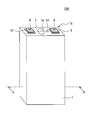
- FIG. 1 is a perspective view showing a square non-aqueous electrolyte secondary battery which is an example of the embodiment.
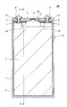
- FIG. 2 is a front vertical sectional view seen in the direction AA of FIG.
- FIG. 3 is a perspective view of the electrode group of the non-aqueous electrolyte secondary battery shown in FIG. 2, and is a developed view of the unwound end of the electrode body on the front side.
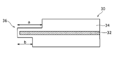
- FIG. 4 is a front view showing the negative electrode plate in an example of the embodiment in an unfolded state.
- FIG. 5 is a cross-sectional view taken along the line CC of FIG. FIG.
- FIG. 6 is a photograph of a cross section of the negative electrode plate cut along the thickness direction in an example of the embodiment, in which the vicinity of the tip portion is taken with a scanning electron microscope.
- FIG. 7 is an enlarged cross-sectional view of the periphery of the negative electrode tab in the cross section taken along the line BB of FIG.
- FIG. 8 is a diagram illustrating a method of cutting the negative electrode plate in an example of the embodiment.
- the vertical direction of the paper surface of FIGS. 1 to 3 may be represented by “up and down”, the horizontal direction by “left and right”, and the depth direction by “front and back”.
- FIG. 1 is a perspective view showing the appearance of the non-aqueous electrolyte secondary battery 100 which is an example of the embodiment
- FIG. 2 is a front vertical sectional view seen in the direction of AA in FIG.
- the non-aqueous electrolyte secondary battery 100 includes a battery case 16 having an exterior body 1 having an opening at the top and a sealing plate 2 for sealing the opening.
- the exterior body 1 and the sealing plate 2 are each preferably made of metal, and can be made of, for example, aluminum or an aluminum alloy.
- the exterior body 1 is a square bottomed tubular exterior body having a bottom portion and a side wall and having an opening at a position facing the bottom portion.
- the non-aqueous electrolyte secondary battery 100 shown in FIG. 1 is an example of a square non-aqueous electrolyte secondary battery having a rectangular battery case 16, but the non-aqueous electrolyte secondary battery of the present embodiment is not limited thereto.
- a battery case having an opening having a circular, oval, or elliptical shape may be used, or a laminated non-aqueous electrolyte secondary battery having a battery case made of a laminated sheet formed by laminating a metal foil with a resin sheet may be used. ..
- the sealing plate 2 is connected to the opening edge of the square exterior body 1 by laser welding or the like.
- the sealing plate 2 has an electrolytic solution injection hole 13.
- the electrolytic solution injection hole 13 is sealed by a sealing plug 14 after injecting an electrolytic solution described later.
- the sealing plate 2 has a gas discharge valve 15.
- the gas discharge valve 15 operates when the pressure inside the battery becomes equal to or higher than a predetermined value, and discharges the gas inside the battery to the outside of the battery.
- a positive electrode terminal 4 is attached to the sealing plate 2 so as to project outside the battery case 16. Specifically, the positive electrode terminal 4 is inserted into the positive electrode terminal mounting hole formed in the sealing plate 2, and is arranged inside the battery and the external insulating member 9 arranged on the outside of the battery in the positive electrode terminal mounting hole. It is attached to the sealing plate 2 in a state of being electrically insulated from the sealing plate 2 by the internal insulating member 8. The positive electrode terminal 4 is electrically connected to the positive electrode current collector 5 in the battery case 16.
- the positive electrode current collector 5 is provided on the sealing plate 2 with the internal insulating member 8 interposed therebetween. It is preferable that the inner side insulating member 8 and the outer side insulating member 9 are each made of resin.
- the negative electrode terminal 6 is attached to the sealing plate 2 so as to project to the outside of the battery case 16. Specifically, the negative electrode terminal 6 is inserted into the negative electrode terminal mounting hole formed in the sealing plate 2, and is arranged inside the battery and the external insulating member 11 arranged on the outside of the battery in the negative electrode terminal mounting hole. It is attached to the sealing plate 2 in a state of being electrically insulated from the sealing plate 2 by the internal insulating member 10. The negative electrode terminal 6 is electrically connected to the negative electrode current collector 7 in the battery case 16. The negative electrode current collector 7 is provided on the sealing plate 2 with the internal insulating member 10 interposed therebetween. It is preferable that the inner side insulating member 10 and the outer side insulating member 11 are each made of resin.
- the non-aqueous electrolyte secondary battery 100 includes an electrode group 3 and an electrolytic solution, and the exterior body 1 accommodates a wound electrode group 3 and an electrolytic solution.
- the electrode group 3 includes two electrode bodies having a wound structure in which the positive electrode plate 20 and the negative electrode plate 30 are wound around the separator 40.
- the positive electrode tab 28 and the negative electrode tab 38 project from the positive electrode plate 20 and the negative electrode plate 30, respectively.
- the positive electrode tab 28 and the negative electrode tab 38 are bent in the depth direction, and are connected to the positive electrode current collector 5 and the negative electrode current collector 7 by welding or the like, respectively.
- the electrode body is not limited to the wound type, and may be a laminated type.
- the non-aqueous electrolyte secondary battery 100 can include an insulating sheet 12 arranged between the electrode group 3 and the exterior body 1.
- the insulating sheet 12 has a bottomed box shape or a bag shape having an opening at the top, for example. Since the insulating sheet 12 has a bottomed box shape or a bag shape having an opening at the top, the electrode group 3 can be inserted through the opening of the insulating sheet 12 and the electrode group 3 can be covered by the insulating sheet 12.
- the material of the insulating sheet 12 is any material having electrical insulation, chemical stability that is not affected by the electrolytic solution, and electrical stability that does not electrolyze with respect to the voltage of the non-aqueous electrolyte secondary battery 100. There is no particular limitation.
- a resin material such as polyethylene, polypropylene, or polyfluoroethylene can be used from the viewpoint of industrial versatility, manufacturing cost, and quality stability.
- the electrolytic solution contains a solvent and an electrolyte salt dissolved in the solvent.
- a non-aqueous solvent can be used.
- carbonates include cyclic carbonates such as ethylene carbonate (EC), propylene carbonate (PC), butylene carbonate, and vinylene carbonate; dimethyl carbonate (DMC), ethyl methyl carbonate (EMC), diethyl carbonate (DEC), and methylpropyl carbonate.
- the non-aqueous solvent may contain a halogen substituent in which at least a part of hydrogen in the above solvent is substituted with a halogen atom such as fluorine.
- the electrolytic solution is not limited to the liquid electrolyte, and may be a solid electrolyte using a gel polymer or the like.
- Electrolyte salts include lithium salts. As the lithium salt, LiPF 6 or the like, which is generally used as a supporting salt in the conventional non-aqueous electrolyte secondary battery 100, can be used. Further, an additive such as vinylene carbonate (VC) can be added as appropriate.
- FIG. 3 is a perspective view of an electrode group 3 composed of two wound electrode bodies 3a and 3b, and is a developed view of the unwound end of the electrode body 3a on the front side.
- Each of the electrode bodies 3a and 3b has a winding structure in which the positive electrode plate 20 and the negative electrode plate 30 are wound around the separator 40. Since each of the electrode bodies 3a and 3b is formed by being pressed after being wound, the front side and the back side surfaces are substantially parallel, and the left and right ends are curved and have a flat shape.
- the number of electrode bodies constituting the electrode group 3 is not limited to two, and may be one or three or more.
- a bundle of positive electrode tabs 28 protrudes upward from each of the electrode bodies 3a and 3b.
- the bundle of negative electrode tabs 38 also protrudes upward from each of the electrode bodies 3a and 3b.
- the number of positive electrode tabs and negative electrode tabs and the number of each electrode tab constituting the positive electrode tabs are not particularly limited.
- a porous sheet having ion permeability and insulating property is used for the separator 40.
- the porous sheet include a microporous membrane, a woven fabric, a non-woven fabric and the like.
- an olefin resin such as polyethylene or polypropylene, cellulose or the like is suitable.
- the separator 40 may be a laminate having a cellulose fiber layer and a thermoplastic resin fiber layer such as an olefin resin. Further, it may be a multilayer separator containing a polyethylene layer and a polypropylene layer, and a resin such as an aramid resin or an inorganic fine particle such as alumina or titania coated on the surface of the separator 40 can also be used.
- the positive electrode plate 20 is formed from a strip-shaped positive electrode core 22, a positive electrode mixture layer 24 formed on both sides of the positive electrode core 22, and one end of the positive electrode core 22 in the lateral direction. It has a positive electrode tab 28 extending upward.
- the positive electrode core body 22 a metal foil that is stable in the potential range of the positive electrode plate 20 such as aluminum is used.
- the thickness of the positive electrode core 22 is, for example, 10 to 20 ⁇ m.
- the positive electrode mixture layer 24 is formed in a band shape on at least a part of the surface of the positive electrode core 22 along the longitudinal direction of the positive electrode core 22.
- the positive electrode mixture layer 24 is preferably provided at corresponding positions on both sides of the positive electrode core body 22.
- the positive electrode mixture layer 24 contains a positive electrode active material, a binder, and a conductive material, and a positive electrode active material slurry containing the positive electrode active material, the binder, the conductive material, and the like is applied to both surfaces of the positive electrode core body 22. It can be produced by drying the coating film and then compressing it with a roller or the like.
- the positive electrode active material may contain a small amount of other lithium metal composite oxide or the like, but it is preferable that the lithium metal composite oxide represented by the above general formula is the main component.
- the lithium metal composite oxide may contain elements other than Ni, Co, Mn, and Al.
- examples of other elements include alkali metal elements other than Li, transition metal elements other than Ni, Co, and Mn, alkaline earth metal elements, Group 12 elements, Group 13 elements other than Al, and Group 14 elements.
- Zr, B, Mg, Ti, Fe, Cu, Zn, Sn, Na, K, Ba, Sr, Ca, W, Mo, Nb, Si and the like can be exemplified.
- Inorganic compound particles such as zirconium oxide, tungsten oxide, aluminum oxide, and lanthanoid-containing compounds may be adhered to the particle surface of the lithium metal composite oxide.
- the particle size of the lithium metal composite oxide is not particularly limited, but for example, the average particle size is preferably 2 ⁇ m or more and less than 30 ⁇ m. When the average particle size is less than 2 ⁇ m, the resistance may increase by inhibiting the energization by the conductive material in the positive electrode mixture layer 24. On the other hand, when the average particle size is 30 ⁇ m or more, the load characteristics may be deteriorated due to the decrease in the reaction area.
- the average particle size is the volume average particle size measured by the laser diffraction method, and means the median diameter at which the volume integrated value is 50% in the particle size distribution. The average particle size can be measured using, for example, a laser diffraction / scattering type particle size distribution measuring device (manufactured by HORIBA, Ltd.).
- binder contained in the positive electrode mixture layer 24 examples include fluororesins such as polytetrafluoroethylene (PTFE) and polyvinylidene fluoride (PVdF), polyacrylonitrile (PAN), polyimide resins, acrylic resins, and polyolefin resins. Examples include resin. One type of these binders may be used alone, or a plurality of types may be mixed and used.
- Examples of the conductive material contained in the positive electrode mixture layer 24 include carbon materials such as carbon black (CB), acetylene black (AB), Ketjen black, and graphite.
- carbon black CB
- AB acetylene black
- Ketjen black Ketjen black
- graphite graphite
- the packing density of the positive electrode mixture layer 24 may be 2.0 g / cm 3 to 4.0 g / cm 3 . The higher the packing density of the positive electrode mixture layer 24, the larger the capacity of the battery.
- the positive electrode mixture layer uncoated portion 26 is a region where the positive electrode mixture layer 24 is not formed on the surface of the positive electrode core body 22 and the positive electrode core body 22 is exposed. Further, similarly to the negative electrode plate 30 described later, the positive electrode plate 20 does not have the positive electrode mixture layer uncoated portion 26, and the positive electrode mixture layer 24 is formed on the entire surface of the positive electrode core body 22. Good. Further, in the lateral direction of the positive electrode core body 22, the tip end portion of the end portion on the side where the positive electrode tab 28 extends may be covered with the positive electrode mixture layer 24.
- the positive electrode tab 28 extends from one end of the positive electrode core 22 in the lateral direction.
- the positive electrode plate 20 has a plurality of positive electrode tabs 28 in the longitudinal direction of the positive electrode core body 22, and the distances between the positive electrode tabs 28 in the longitudinal direction of the positive electrode core body 22 are aligned when wound. It has been adjusted.
- a protective layer having a higher electrical resistance than the positive electrode core 22 may be provided so as to cover a part or all of the positive electrode mixture layer uncoated portion 26 including the root of the positive electrode tab 28.
- the protective layer is provided to prevent energization from occurring in an unintended portion of the positive electrode mixture layer uncoated portion 26.
- the thickness of the protective layer is, for example, 20 ⁇ m to 120 ⁇ m, and may be 50 ⁇ m to 100 ⁇ m.
- the protective layer may contain ceramic particles such as alumina, zirconia, titania and silica, and a binder such as polyvinylidene fluoride (PVdF).
- the shape of the positive electrode tab 28 is not particularly limited, but may be, for example, a symmetrical shape. Further, although the positive electrode tabs 28 may have different shapes, it is preferable that the positive electrode tabs 28 have the same shape for bundling.
- the negative electrode plate 30 is formed from a strip-shaped negative electrode core 32, a negative electrode mixture layer 34 formed on both sides of the negative electrode core 32, and one end of the negative electrode core 32 in the lateral direction. It has a negative electrode tab 38 extending upward.
- the negative electrode core 32 a metal foil that is stable in the potential range of the negative electrode plate 30 such as copper can be used.
- the thickness of the negative electrode core 32 is, for example, 5 to 15 ⁇ m.
- the negative electrode mixture layer 34 is formed in a band shape on the surface of the negative electrode core 32 along the longitudinal direction of the negative electrode core 32, and may be formed on the entire surface of the negative electrode core 32. Further, it is preferable that the negative electrode mixture layer 34 is provided at corresponding positions on both surfaces of the negative electrode core body 32.
- the negative electrode plate 30 contains a negative electrode active material and a binder. The negative electrode plate 30 is formed by applying a negative electrode active material slurry containing a negative electrode active material and a binder and the like on the negative electrode core 32, drying the coating film, and then compressing the negative electrode mixture layer 34 with a roller or the like. It can be manufactured by forming it on both sides of the negative electrode core 32.
- Examples of the negative electrode active material include low crystalline carbon-coated graphite formed by forming a low crystalline carbon film on the surface of graphite.
- Low crystalline carbon is a carbon material in which the graphite crystal structure has not been developed and is in an amorphous or polycrystalline state with a disordered layer structure, or a carbon material having a very fine particle size rather than a spherical or scaly shape. Is.
- a carbon material having a d (002) plane spacing greater than 0.340 nm by X-ray diffraction is low crystalline carbon.
- low crystalline carbon examples include hard carbon (non-graphitized carbon), soft carbon (easily graphitized carbon), acetylene black, Ketjen black, thermal black, furnace black and other carbon blacks, and carbon fibers.
- Activated carbon and the like can be mentioned.
- the negative electrode active material is not particularly limited as long as it can reversibly occlude and release lithium ions, and is, for example, an alloy with a carbon material such as natural graphite or artificial graphite, or Li such as silicon (Si) or tin (Sn). It is possible to use a metal to be converted or an oxide containing a metal element such as Si or Sn. Further, the negative electrode mixture layer 34 may contain a lithium titanium composite oxide.
- a known binder can be used as the binder contained in the negative electrode mixture layer 34, and as in the case of the positive electrode mixture layer 24, a fluororesin such as PTFE or PVdF, a PAN, or a polyimide resin can be used. , Acrylic resin, polyolefin resin and the like can be used.
- the binder used when preparing the negative electrode active material slurry using an aqueous solvent includes CMC or a salt thereof, styrene butadiene rubber (SBR), polyacrylic acid (PAA) or a salt thereof, and polyvinyl alcohol (PVA). ) Etc. can be exemplified.
- the packing density of the negative electrode mixture layer 34 may be 1.0 g / cm 3 to 2.0 g / cm 3 . The higher the packing density of the negative electrode mixture layer 34, the larger the capacity of the battery.
- FIG. 4 is a front view showing the negative electrode plate 30 in an unfolded state
- FIG. 5 is a cross-sectional view taken along the line CC of FIG.
- the negative electrode plate 30 has a plurality of negative electrode tabs 38 in the longitudinal direction of the negative electrode core 32, and the distance between the negative electrode tabs 38 in the longitudinal direction of the negative electrode core 32 is wound. It is adjusted to align when it is done.
- the shape of the negative electrode tab 38 is not particularly limited, but may be, for example, a symmetrical shape. Further, although the negative electrode tabs 38 may have different shapes, it is preferable that the negative electrode tabs 38 have the same shape for bundling.
- the tip portion 36 of the negative electrode core body 32 is covered with the negative electrode mixture layer 34.
- the tip portion 36 refers to the end face of the negative electrode core 32 at the end on the side where the negative electrode tab 38 of the negative electrode core 32 extends, and the end face of the negative electrode core 32 on the surface of the negative electrode core 32. Adjacent part.
- the thickness of the negative electrode mixture layer 34 covering the tip portion 36 may be thinner than the thickness of one side of the negative electrode mixture layer 34 formed on the inner side of the tip portion 36 of the negative electrode core body 32.
- the width of the tip portion 36 in the lateral direction of the negative electrode core 32 may be such that the width a on one surface is larger than the width b on the other surface.
- the tip portion 36 is composed of an end surface of the negative electrode core body 32 and a portion having a width a and a width b adjacent to the end surface of the negative electrode core body 32 on the surface of the negative electrode core body 32.
- the thickness of the negative electrode mixture layer 34 covering the tip portion 36 is substantially the same, but may be non-uniform.
- the width a of the tip portion 36 on one surface is, for example, 30 ⁇ m to 100 ⁇ m.
- the width b of the tip portion 36 on the other surface is, for example, 5 ⁇ m to 50 ⁇ m.
- FIG. 6 is a photograph of the vicinity of the tip portion 36 taken with a scanning electron microscope in a cross section obtained by cutting the negative electrode plate 30 along the thickness direction.
- the negative electrode plate 30 has a thickness of 169 ⁇ m, and the negative electrode core 32 is a copper plate having a thickness of 8 ⁇ m.
- the negative electrode mixture layer 34 is composed of 98.3% by mass of graphite, 0.7% by mass of CMC, and 1.0% by mass of SBR, and has a packing density of 1.6 g / cm 3 .
- the method for manufacturing the negative electrode plate 30 will be described in detail later, but the vicinity of the tip portion 36 is cut by the laser beam.
- the negative electrode plate 30 was irradiated with a laser beam having a wavelength of 1.06 ⁇ m, a peak output of 37.5 kW, a repetition frequency of 20 kHz, and a pulse width of 100 ns at a scanning speed of 30 m / min while being focused by a lens having a focal length of 100 mm.
- the energy per plate thickness was 0.89 mJ / mm ⁇ ⁇ m.
- the number of irradiations per 1 mm is the number of laser beams emitted while the electrode plate advances by 1 mm.
- the laser beam was irradiated so that the negative electrode plate 30 was located at a position substantially the beam waist of the laser beam.
- the tip portion 36 is covered with the negative electrode mixture layer 34. Further, the thickness of the negative electrode mixture layer 34 covering the tip portion 36 is thinner than the thickness of one side of the negative electrode mixture layer 34 formed on the inner side of the tip portion 36.
- the tip portion 36 may have a claw shape in a cross-sectional view cut along the thickness direction of the negative electrode core body 32.
- the binding force between the tip portion 36 and the negative electrode mixture layer 34 is improved, so that the falling off of the active material can be further suppressed.
- the claw shape is coated on the negative electrode mixture layer 34, it is possible to prevent the claw shape from coming into contact with the separator 40 and being damaged.
- FIG. 7 is an enlarged cross-sectional view of the periphery of the negative electrode tab 38 in the cross section taken along the line BB of FIG.
- the base of the negative electrode tab 38a extending from the electrode body 3a is tilted toward the front side in the depth direction, and is connected to the negative electrode current collector 7 attached to the sealing plate 2 after being bent.
- the surface on the side where the width of the tip portion 36 (not shown in FIG. 7) is a faces the back side in the depth direction, and the surface and the electrode on the side where the width of the tip portion 36 of the negative electrode tab 38a is a.
- the angle ⁇ 1 formed by the upper surface 50a of the body 3a may be an obtuse angle.
- the negative electrode tab 38b extending from the electrode body 3b has its root tilted toward the depth side in the depth direction, and is connected to the negative electrode current collector 7 attached to the sealing plate 2 after being bent.
- the surface on the side where the width of the tip portion 36 (not shown in FIG. 7) is a faces the front side in the depth direction, and the surface and the electrode on the side where the width of the tip portion 36 of the negative electrode tab 38b is a.
- the angle ⁇ 2 formed by the upper surface 50b of the body 3b may be an obtuse angle. ⁇ 1 and ⁇ 2 may have the same angle or may be different.
- the surfaces of the tip portions 36 can be aligned by moving the negative electrode tabs 38a and 38b toward only one side with respect to the winding cores of the respective electrode bodies 3a and 3b.
- the negative electrode tabs 38a and 38b are closer to the side closer to the exterior body 1 in the depth direction. Therefore, when the electrode group 3 is housed in the non-aqueous electrolyte secondary battery 100 as shown in FIG. 7, the negative electrode tab 38
- the surface of the tip portion 36 on the side where the width is a faces the inside of the winding.
- the method for manufacturing the negative electrode plate 30 includes a mixture layer forming step and a cutting step.
- the mixture layer forming step the band-shaped negative electrode mixture layer 34 is formed on both sides of the negative electrode core 32 base material along the longitudinal direction of the band-shaped negative electrode core 32 base material.
- the negative electrode mixture layer 34 is formed by applying a negative electrode active material slurry containing a negative electrode active material, a binder and the like on the surface of the base material for the negative electrode core 32, drying the coating film, and then compressing the coating film with a roller or the like. It can be produced by forming the negative electrode mixture layer 34 on both sides of the negative electrode core 32.
- a negative electrode plate 30 having a negative electrode tab 38 extending from one end in the direction is cut out.
- the tip portion 36 of the negative electrode core body 32 is covered with the negative electrode mixture layer 34 at the end portion on the side where the tab extends.
- FIG. 8 is a diagram illustrating an example of a method for cutting the negative electrode plate 30.
- the dotted line in FIG. 8 shows the scanning trace of the laser beam.
- Band-shaped negative electrode mixture layers 34 are formed on both sides of the negative electrode core 32 base material along the longitudinal direction of the band-shaped negative electrode core 32 base material, and the negative electrode mixture layer 34 is not formed on both sides.
- the negative electrode core 32 is exposed.
- the laser beam is scanned according to the shapes of the tip 36 and the negative electrode tab 38.
- the tip portion 36 is formed by scanning the portion where the negative electrode mixture layer 34 is formed on the inner side of the boundary between the portion where the negative electrode core 32 is exposed and the portion where the negative electrode mixture layer 34 is formed. It is cut out.
- the negative electrode tab 38 projects outward from the tip portion 36, and is cut out by cutting the exposed portion of the negative electrode core 32 while including the portion where the negative electrode mixture layer 34 is formed at the root portion.
- the characteristics of the laser beam and the laser irradiation optical system are not particularly limited, but are desired by, for example, appropriately adjusting within the range of the conditions shown in Table 1 according to the thickness, composition, etc. of the negative electrode core 32 and the negative electrode mixture layer 34.
- the negative electrode plate 30 of the above can be manufactured.
- the repetition frequency is small, the pulse energy becomes large and the cut surface of the electrode plate becomes rough, so 10 kHz or more is preferable. If the repetition frequency is large, the pulse energy becomes small, the workability deteriorates, and the line speed becomes slow, so 150 kHz or less. Is preferable.
- the energy per electrode plate thickness is small, the mixture will peel off from the core surface, so 0.33 mJ / mm ⁇ ⁇ m or more is preferable, and if the energy per electrode plate thickness is large, the width a of the tip portion 36 becomes too large. Therefore, it is preferably 4.13 mJ / mm ⁇ ⁇ m or less.
- the pulse width is preferably 10 to 300 ns, more preferably 50 to 200 ns.
- the base material for the negative electrode core 32 may be moved, or the laser beam may be moved using, for example, a galvano scanner system. Further, the end portion, the winding start end, and the winding end on the side opposite to the extending side of the negative electrode tab 38 may be cut using a laser beam as described above, or may be cut using a slit blade. You may.
- the electrode plate of the present embodiment it is possible to suppress the dropping of the active material.
Landscapes
- Chemical & Material Sciences (AREA)
- Chemical Kinetics & Catalysis (AREA)
- Electrochemistry (AREA)
- General Chemical & Material Sciences (AREA)
- Engineering & Computer Science (AREA)
- Manufacturing & Machinery (AREA)
- Materials Engineering (AREA)
- Secondary Cells (AREA)
Abstract
極板は、巻回形又は積層形の電極体に含まれる極板であって、帯状の極板芯体と、極板芯体の両面に形成された合剤層と、極板芯体の短手方向の一方の端部から延出したタブと、を備え、タブが延出する側の端部において、極板芯体の先端部は合剤層に被覆されている。
Description
本開示は、極板、非水電解質二次電池、及び極板の製造方法に関する。
非水電解質二次電池を構成する正極又は負極の極板は、各々の芯体の表面に合剤層を有している。合剤層に含まれる活物質が電池内部で脱落すると内部短絡が発生する可能性があり、活物質の脱落を抑制することで電池の信頼性を向上させることができる。活物質の脱落は特に極板の端部で発生しやすいので、例えば特許文献1には、極板の端部から合剤層を除去した二次電池が開示されている。
特許文献1に開示された方法では、芯体が露出した部分と芯体の表面に合剤層が形成された部分との界面で活物質の脱落が生じる可能性があり、未だに改良の余地がある。
本開示の一形態である極板は、巻回形又は積層形の電極体に含まれる極板であって、帯状の極板芯体と、極板芯体の両面に形成された合剤層と、極板芯体の短手方向の一方の端部から延出したタブと、を備え、タブが延出する側の端部において、極板芯体の先端部は合剤層に被覆されていることを特徴とする。
本開示の一態様である非水電解質二次電池は、上記の極板を含む巻回形又は積層形の電極体と、電極体を収容する開口を有する外装体と、開口を封口し、タブと接続する封口板と、を備える非水電解質二次電池であって、極板芯体の短手方向の先端部の幅は、一方の面における幅aが、他方の面における幅bよりも大きく、タブは根元が傾倒しており、タブの先端部の幅がaである側の面と電極体の上面とのなす角は鈍角であることを特徴とする。
本開示の一形態である極板の製造方法は、巻回形又は積層形の電極体に含まれる極板の製造方法であって、帯状の極板芯体用基材の長手方向に沿って極板芯体用基材の両面に帯状の合剤層を形成する合剤層形成ステップと、極板芯体用基材の一方の面にレーザ光を照射することで、両面に合剤層が形成された帯状の極板芯体と、極板芯体の短手方向の一方の端部から延出したタブと、を有する極板を切り出す切断ステップと、を含み、切断ステップで切り出された極板は、タブが延出する側の端部において、極板芯体の先端部が合剤層に被覆されていることを特徴とする。
本開示の一態様によれば、極板からの活物質の脱落を抑制することができる。
以下、実施形態の一例について詳細に説明する。なお、本明細書において、図1~図3の紙面縦方向を「上、下」、横方向を「左、右」、奥行方向を「手前、奥」で表すことがある。
図1及び図2を参照しつつ、実施形態の一例である非水電解質二次電池100の構成を説明する。図1は、実施形態の一例である非水電解質二次電池100の外観を示す斜視図であり、図2は、図1におけるA-A方向に見た正面縦断面図である。図1及び図2に示すように、非水電解質二次電池100は、上部に開口を有する外装体1と、当該開口を封口する封口板2とを有する電池ケース16を備える。外装体1及び封口板2は、それぞれ金属製であることが好ましく、例えば、アルミニウム又はアルミニウム合金製とすることができる。外装体1は、底部と側壁を有し、底部と対向する位置に開口を有する角形の有底筒状の外装体である。図1に示す非水電解質二次電池100は、角形の電池ケース16を有する角形非水電解質二次電池の例であるが、本実施形態の非水電解質二次電池は、これに限定されない。例えば、開口部の形状が円形、長円形、楕円形の電池ケースでもよいし、金属箔を樹脂シートでラミネートして形成されたラミネートシート製電池ケースを有するラミネート非水電解質二次電池等でもよい。封口板2は、角形の外装体1の開口縁部にレーザ溶接等により接続される。
封口板2は電解液注入孔13を有する。電解液注入孔13は、後述する電解液を注入した後、封止栓14により封止される。また、封口板2は、ガス排出弁15を有する。このガス排出弁15は電池内部の圧力が所定値以上となった場合に作動し、電池内部のガスを電池外部に排出する。
封口板2には、電池ケース16外に突出するように正極端子4が取り付けられている。具体的には、正極端子4は、封口板2に形成された正極端子取り付け孔に挿入されており、正極端子取り付け孔の電池外側に配置された外部側絶縁部材9、電池内側に配置された内部側絶縁部材8により封口板2と電気的に絶縁された状態で封口板2に取り付けられている。正極端子4は、電池ケース16内で正極集電体5と電気的に接続している。正極集電体5は、内部側絶縁部材8を挟んで封口板2に設けられている。内部側絶縁部材8及び外部側絶縁部材9はそれぞれ樹脂製であることが好ましい。
また、封口板2には、電池ケース16外に突出するように負極端子6が取り付けられている。具体的には、負極端子6は、封口板2に形成された負極端子取り付け孔に挿入されており、負極端子取り付け孔の電池外側に配置された外部側絶縁部材11、電池内側に配置された内部側絶縁部材10により封口板2と電気的に絶縁された状態で封口板2に取り付けられている。負極端子6は、電池ケース16内で負極集電体7と電気的に接続している。負極集電体7は、内部側絶縁部材10を挟んで封口板2に設けられている。内部側絶縁部材10及び外部側絶縁部材11はそれぞれ樹脂製であることが好ましい。
非水電解質二次電池100は電極群3と電解液を備え、外装体1は巻回形の電極群3と電解液を収容する。後述するように、電極群3は、正極板20と負極板30とがセパレータ40を介して巻回された巻回構造を有する電極体を2つ含んでいる。電極群3の上部において、正極板20及び負極板30から各々正極タブ28及び負極タブ38が突出している。正極タブ28及び負極タブ38は、奥行方向に屈曲しており、それぞれ正極集電体5及び負極集電体7に溶接等により接続されている。電極体は、巻回形に限定されず、積層形でもよい。
非水電解質二次電池100は、図2に示すように、電極群3と外装体1との間に配置される絶縁シート12を備えることができる。絶縁シート12は、例えば、外装体1と同様に、上部に開口を有する有底箱状又は袋状の形状を有している。絶縁シート12が上部に開口を有する有底箱状又は袋状の形状を有することで、電極群3を絶縁シート12の開口から挿入し、絶縁シート12によって電極群3を覆うことができる。絶縁シート12の素材は、電気的な絶縁性、電解液に侵されない化学的安定性、及び非水電解質二次電池100の電圧に対して電気分解しない電気的安定性を有する素材であれば、特に限定されない。絶縁シート12の素材としては、例えば、工業的な汎用性、製造コスト及び品質安定性の観点から、ポリエチレン、ポリプロピレン、ポリフッ化エチレン等の樹脂材料を用いることができる。
電解液は、溶媒と、溶媒に溶解した電解質塩とを含む。溶媒は、非水溶媒を使用できる。非水溶媒には、例えばカーボネート類、エステル類、エーテル類、ニトリル類、アミド類、およびこれらの2種以上の混合溶媒等を用いてもよい。カーボネート類としては、エチレンカーボネート(EC)、プロピレンカーボネート(PC)、ブチレンカーボネート、ビニレンカーボネート等の環状カーボネート類;ジメチルカーボネート(DMC)、エチルメチルカーボネート(EMC)、ジエチルカーボネート(DEC)、メチルプロピルカーボネート、エチルプロピルカーボネート、メチルイソプロピルカーボネート等の鎖状カーボネート類が挙げられる。非水溶媒は、上記の溶媒の水素の少なくとも一部をフッ素等のハロゲン原子で置換したハロゲン置換体を含有していてもよい。なお、電解液は液体電解質に限定されず、ゲル状ポリマー等を用いた固体電解質であってもよい。電解質塩は、リチウム塩を含む。リチウム塩には、従来の非水電解質二次電池100において支持塩として一般に使用されているLiPF6等を用いることができる。また、適宜ビニレンカーボネート(VC)等の添加剤を添加することもできる。
図3は、巻回された2つの電極体3a、3bから成る電極群3の斜視図であり、手前側の電極体3aの巻外端を展開した図である。電極体3a、3bは、いずれも正極板20と負極板30とがセパレータ40を介して巻回された巻回構造を有している。電極体3a、3bは、各々、巻回した後にプレスされて成形されるため、手前側と奥側の面が略平行で、左右端が湾曲した扁平な形状をしている。電極群3を構成する電極体の数は2つに限定されず、1つまたは3つ以上であってもよい。また、正極タブ28の束(以下、「正極タブ群」という場合がある)が電極体3a、3bの各々から上方に突出している。負極タブ38の束(以下、「負極タブ群」という場合がある)も正極タブ群と同様に、電極体3a、3bの各々から上方に突出している。正極タブ群及び負極タブ群の数や、これを構成する各電極タブの枚数は特に限定されない。
セパレータ40には、イオン透過性及び絶縁性を有する多孔性シートが用いられる。多孔性シートの具体例としては、微多孔膜、織布、不織布等が挙げられる。セパレータ40の材質としては、ポリエチレン、ポリプロピレン等のオレフィン系樹脂、セルロース等が好適である。セパレータ40は、セルロース繊維層及びオレフィン系樹脂等の熱可塑性樹脂繊維層を有する積層体であってもよい。また、ポリエチレン層及びポリプロピレン層を含む多層セパレータであってもよく、セパレータ40の表面にアラミド系樹脂等の樹脂、又はアルミナ、チタニア等の無機微粒子が塗布されたものを用いることもできる。
以下、図3~図5を参照しつつ、電極群3を構成する正極板20及び負極板30について詳説する。
まず、正極板20について説明する。図3に示すように、正極板20は、帯状の正極芯体22、正極芯体22の両面に形成された正極合剤層24、及び正極芯体22の短手方向の一方の端部から上方に延出した正極タブ28を有する。
正極芯体22には、アルミニウムなどの正極板20の電位範囲で安定な金属の箔が用いられる。正極芯体22の厚みは、例えば10~20μmである。
正極合剤層24は、正極芯体22の長手方向に沿って、正極芯体22の表面の少なくとも一部に帯状に形成されている。正極合剤層24は、正極芯体22の両面の対応する位置に設けられることが好ましい。正極合剤層24は、正極活物質、結着材、及び導電材を含み、正極芯体22の両面に正極活物質、結着材、及び導電材等を含む正極活物質スラリーを塗布し、塗膜を乾燥させた後、ローラ等により圧縮することにより作製できる。
正極活物質としては、一般式Li1+xMaO2+b(式中、x、a、及びbはx+a=1、-0.2<x≦0.2、-0.1≦b≦0.1の条件を満たし、MはNiとCoを含み、MnとAlからなる群より選択された少なくとも一種の元素を含む)で表されるリチウム金属複合酸化物を含有する。正極活物質として、他のリチウム金属複合酸化物等が少量含まれていてもよいが、上記一般式で表されるリチウム金属複合酸化物を主成分とすることが好ましい。
リチウム金属複合酸化物は、Ni、Co、Mn、及びAl以外の他の元素を含んでいてもよい。他の元素としては、Li以外のアルカリ金属元素、Ni、Co、Mn以外の遷移金属元素、アルカリ土類金属元素、第12族元素、Al以外の第13族元素、並びに第14族元素が挙げられる。具体的には、Zr、B、Mg、Ti、Fe、Cu、Zn、Sn、Na、K、Ba、Sr、Ca、W、Mo、Nb、Si等が例示できる。なお、リチウム金属複合酸化物の粒子表面には、酸化ジルコニウム、酸化タングステン、酸化アルミニウム、ランタノイド含有化合物等の無機化合物粒子などが固着していてもよい。
リチウム金属複合酸化物の粒径は、特に限定されないが、例えば平均粒径が2μm以上30μm未満であることが好ましい。平均粒径が2μm未満である場合、正極合剤層24内の導電材による通電を阻害して抵抗増加する場合がある。一方、平均粒径が30μm以上である場合、反応面積の低下により、負荷特性が低下する場合がある。平均粒径とは、レーザ回折法によって測定される体積平均粒径であって、粒子径分布において体積積算値が50%となるメジアン径を意味する。平均粒径は、例えば、レーザ回折散乱式粒度分布測定装置(株式会社堀場製作所製)を用いて測定できる。
正極合剤層24に含まれる結着材としては、ポリテトラフルオロエチレン(PTFE)、ポリフッ化ビニリデン(PVdF)等のフッ素系樹脂、ポリアクリロニトリル(PAN)、ポリイミド系樹脂、アクリル系樹脂、ポリオレフィン系樹脂などが挙げられる。これらの結着材は、1種類を単独で用いてもよく、複数種を混合して用いてもよい。
正極合剤層24に含まれる導電材としては、カーボンブラック(CB)、アセチレンブラック(AB)、ケッチェンブラック、黒鉛等の炭素材料などが挙げられる。これらの導電材は、1種類を単独で用いてもよく、複数種を混合して用いてもよい。
正極合剤層24の充填密度は2.0g/cm3~4.0g/cm3としてもよい。正極合剤層24の充填密度が高い方が電池の容量は大きくなる。
図3に示すように、正極合剤層未塗布部26は、正極芯体22の表面において、正極合剤層24が形成されておらず、正極芯体22が露出した領域である。また、正極板20には、後述する負極板30と同様に、正極合剤層未塗布部26が存在せず、正極合剤層24が正極芯体22の表面の全体に形成されていてもよい。また、正極芯体22の短手方向において、正極タブ28が延出する側の端部の先端部が正極合剤層24で被覆されていてもよい。
正極タブ28は、正極芯体22の短手方向の一方の端部から延出している。正極板20は、正極芯体22の長手方向に複数の正極タブ28を有しており、正極芯体22の長手方向における正極タブ28の間の距離は巻回された際に整列するように調整されている。
正極タブ28の根元を含めて正極合剤層未塗布部26の一部または全てを覆うように、正極芯体22よりも電気抵抗が高い保護層を設けてもよい。保護層は、正極合剤層未塗布部26の意図しない部分で通電が起こるのを抑制するために設けられる。保護層の厚さは、例えば、20μm~120μmであり、50μm~100μmであってもよい。保護層は、アルミナ、ジルコニア、チタニア及びシリカ等のセラミック粒子、及びポリフッ化ビニリデン(PVdF)等の結着材を含んでもよい。
正極タブ28の形状は、特に限定されないが、例えば、左右対称の形状であってもよい。また、正極タブ28は各々の形状が異なっていてもよいが、束ねるためには同じ形状であることが好ましい。
次に、負極板30について説明する。図3に示すように、負極板30は、帯状の負極芯体32、負極芯体32の両面に形成された負極合剤層34、及び負極芯体32の短手方向の一方の端部から上方に延出した負極タブ38を有する。
負極芯体32には、銅などの負極板30の電位範囲で安定な金属の箔を用いることができる。負極芯体32の厚みは、例えば5~15μmである。
負極合剤層34は、負極芯体32の長手方向に沿って、負極芯体32の表面に帯状に形成されており、負極芯体32の表面の全体に形成されていてもよい。また、負極合剤層34は、負極芯体32の両面の対応する位置に設けられることが好ましい。負極板30は、負極活物質及び結着材を含む。負極板30は、負極芯体32上に負極活物質、及び結着材等を含む負極活物質スラリーを塗布し、塗膜を乾燥させた後、ローラ等により圧縮して負極合剤層34を負極芯体32の両面に形成することにより作製できる。
負極活物質は、例えば黒鉛の表面に低結晶性炭素の被膜を形成してなる低結晶性炭素被覆黒鉛が挙げられる。低結晶性炭素は、グラファイト結晶構造が発達していない、アモルファス若しくは微結晶で乱層構造な状態の炭素材料であるか、または、球形や鱗片形状でなく非常に微細な粒子径をもつ炭素材料である。例えば、X線回折によるd(002)面間隔が0.340nmより大きい炭素材料は低結晶性炭素である。また、走査型電子顕微鏡(SEM)等により観察され、測定される一次粒子の平均粒径が1μm以下である炭素材料も低結晶性炭素である。低結晶性炭素の具体例としては、例えば、ハードカーボン(難黒鉛化炭素)、ソフトカーボン(易黒鉛化炭素)、アセチレンブラック、ケッチェンブラック、サーマルブラック、ファーネスブラック等のカーボンブラック、カーボンファイバー、活性炭等が挙げられる。負極活物質としては、リチウムイオンを可逆的に吸蔵、放出できるものであれば特に限定されず、例えば天然黒鉛、人造黒鉛等の炭素材料、ケイ素(Si)、錫(Sn)等のLiと合金化する金属、又はSi、Sn等の金属元素を含む酸化物などを用いることができる。また、負極合剤層34は、リチウムチタン複合酸化物を含んでいてもよい。
負極合剤層34に含まれる結着材には、公知の結着材を用いることができ、正極合剤層24の場合と同様に、PTFE、PVdF等のフッ素系樹脂、PAN、ポリイミド系樹脂、アクリル系樹脂、並びに、ポリオレフィン系樹脂等を用いることができる。また、水系溶媒を用いて負極活物質スラリーを調製する場合に用いられる結着材としては、CMC又はその塩、スチレンブタジエンゴム(SBR)、ポリアクリル酸(PAA)又はその塩、ポリビニルアルコール(PVA)等が例示できる。
負極合剤層34の充填密度は1.0g/cm3~2.0g/cm3としてもよい。負極合剤層34の充填密度が高い方が電池の容量は大きくなる。
次に、図4及び図5を参照しつつ、負極板30について説明する。図4は負極板30を展開状態で示した正面図であり、図5は図4のC-C線に沿った断面図である。図4に示すように、負極板30は、負極芯体32の長手方向に複数の負極タブ38を有しており、負極芯体32の長手方向における各負極タブ38の間の距離は巻回された際に整列するように調整されている。
負極タブ38の形状は、特に限定されないが、例えば、左右対称の形状であってもよい。また、負極タブ38は各々の形状が異なっていてもよいが、束ねるためには同じ形状であることが好ましい。
図5に示すように、負極タブ38が延出する側の端部において、負極芯体32の先端部36は、負極合剤層34に被覆されている。これにより、先端部36において、負極芯体32が露出した部分と負極芯体32の表面に負極合剤層34が形成された部分との界面が存在しないので、負極板30からの負極活物質の脱落を抑制することができる。ここで、先端部36とは、負極芯体32の負極タブ38が延出する側の端部において、負極芯体32の端面、及び、負極芯体32の表面において負極芯体32の端面に隣接した部分とをいう。
先端部36を被覆する負極合剤層34の厚みは、負極芯体32の先端部36よりも内部側に形成された負極合剤層34の片面の厚みよりも薄くてもよい。
また、負極芯体32の短手方向の先端部36の幅は、一方の面における幅aが、他方の面における幅bよりも大きくてもよい。図5において、先端部36は、負極芯体32の端面、並びに、負極芯体32の表面において負極芯体32の端面に隣接した幅a及び幅bの部分からなる。また、図5において先端部36を被覆する負極合剤層34の厚みは、略同じであるが、不均一でもよい。
一方の面における先端部36の幅aは、例えば、30μm~100μmである。また、他方の面における先端部36の幅bは、例えば、5μm~50μmである。
図6は、負極板30を厚み方向に沿って切断した断面において、先端部36近傍を走査型電子顕微鏡で撮影した写真である。負極板30の厚みは169μmであり、負極芯体32は厚み8μmの銅板である。負極合剤層34は、98.3質量%の黒鉛、0.7質量%のCMC、1.0質量%のSBRからなり、充填密度は1.6g/cm3である。負極板30の製造方法について詳細は後述するが、先端部36近傍はレーザ光によって切断される。波長1.06μm、ピーク出力37.5kW、繰り返し周波数20kHz、パルス幅100nsのレーザ光を、焦点距離100mmのレンズで集光しつつ30m/minの走査速度で上記の負極板30に照射した。極板厚み当たりのエネルギーは0.89mJ/mm・μmであった。極板厚み当たりのエネルギーは、「極板厚み当たりのエネルギー=パルスエネルギー(mJ)×1mm当たりの照射回数/極板厚み(μm)」で表される。ここで、1mm当たりの照射回数は、極板が1mm進む間に照射されるレーザ光の回数である。負極板30がレーザ光の略ビームウエストの位置になるようにしてレーザ光を照射した。図6においては、図5に示した負極板30の断面図のように、先端部36が負極合剤層34で被覆されている。また、先端部36を被覆する負極合剤層34の厚みは、先端部36よりも内部側に形成された負極合剤層34の片面の厚みよりも薄い。
図6に示すように、先端部36は、負極芯体32の厚み方向に沿って切断した断面視で鉤爪形状を有してもよい。これにより、先端部36と負極合剤層34との結着力が向上するので活物質の脱落をさらに抑制できる。また、鉤爪形状は負極合剤層34に被覆されているので、鉤爪形状がセパレータ40に接触して傷つけることを抑制できる。
次に、図7を参照しつつ、非水電解質二次電池100内部での負極タブ38について説明する。図7は、図2のB-B線に沿った断面において、負極タブ38周辺を拡大した断面図である。電極体3aから延伸する負極タブ38aは、根元が奥行方向の手前側に傾倒しており、屈曲した後に封口板2に取り付けられた負極集電体7に接続している。ここで、図7に図示しない先端部36の幅がaである側の面は、奥行き方向の奥側を向いていて、負極タブ38aの先端部36の幅がaである側の面と電極体3aの上面50aとのなす角α1は鈍角になっていてもよい。また、電極体3bから延伸する負極タブ38bは、根元が奥行方向の奥側に傾倒しており、屈曲した後に封口板2に取り付けられた負極集電体7に接続している。ここで、図7に図示しない先端部36の幅がaである側の面は、奥行き方向の手前側を向いていて、負極タブ38bの先端部36の幅がaである側の面と電極体3bの上面50bとのなす角α2は鈍角になっていてもよい。α1とα2とは同じ角度であってもよいし、異なっていてもよい。
また、図3に示すように、負極タブ38a、38bを各々の電極体3a、3bの巻芯に対して一方の側のみに寄せることで先端部36の面を揃えることができる。図3においては、負極タブ38a、38bが奥行方向の外装体1に近い側に寄っているので、図7のように非水電解質二次電池100に電極群3を収容した時には、負極タブ38の先端部36の幅がaである側の面は、巻内側に向いている。
次に、負極板30の製造方法について説明する。負極板30の製造方法は、合剤層形成ステップと切断ステップとを含む。合剤層形成ステップでは、帯状の負極芯体32用基材の長手方向に沿って負極芯体32用基材の両面に帯状の負極合剤層34を形成する。負極合剤層34は、負極芯体32用基材の表面に負極活物質、及び結着材等を含む負極活物質スラリーを塗布し、塗膜を乾燥させた後、ローラ等により圧縮して負極合剤層34を負極芯体32の両面に形成することにより作製できる。切断ステップでは、負極芯体32用基材の一方の面にレーザ光を照射することで、両面に負極合剤層34が形成された帯状の負極芯体32と、負極芯体32の短手方向の一方の端部から延出した負極タブ38と、を有する負極板30を切り出す。切断ステップで切り出された負極板30は、タブが延出する側の端部において、負極芯体32の先端部36が負極合剤層34に被覆されている。
以下、負極板30の切断方法について説明するが、正極板20についても同様に切断してもよい。図8は、負極板30の切断方法の一例を説明する図である。図8の点線は、レーザ光の走査跡を示す。帯状の負極芯体32用基材の長手方向に沿って負極芯体32用基材の両面に帯状の負極合剤層34が形成されており、負極合剤層34が形成されていない部分には負極芯体32が露出している。切断ステップにおいて、レーザ光は、先端部36及び負極タブ38の形状に合わせて走査される。先端部36は、負極芯体32が露出した部分と負極合剤層34が形成された部分の境界よりも内部側の、負極合剤層34が形成された部分をレーザ光が走査することで切り出される。負極タブ38は、先端部36から外部側に突出しており、根元部分に負極合剤層34が形成された部分を含みつつ、負極芯体32が露出した部分を切断することで切り出される。
レーザ光の特性及びレーザ照射光学系は、特に限定されないが、例えば表1の条件の範囲で、負極芯体32及び負極合剤層34の厚み、組成等に合わせて適宜調整することで、所望の負極板30を製造することができる。
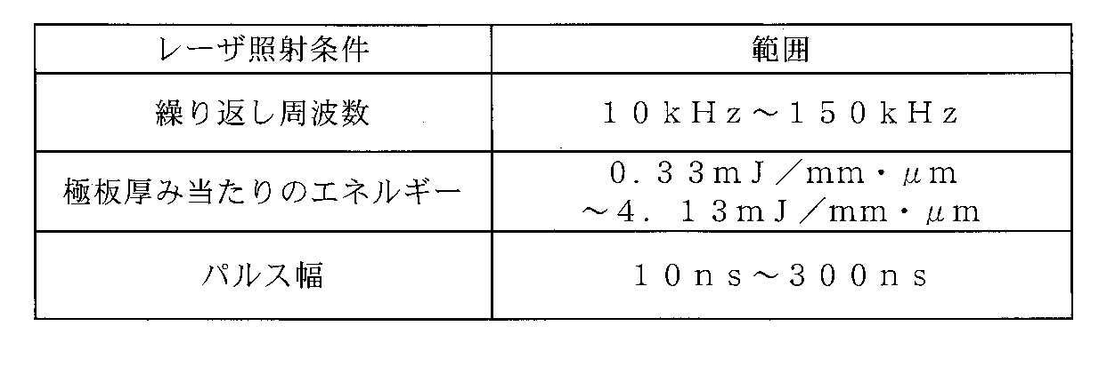
繰り返し周波数が小さいと、パルスエネルギーが大きくなって極板切断面が粗くなるため10kHz以上が好ましく、繰り返し周波数が大きいと、パルスエネルギーが小さくなって加工性が悪くなりラインスピードが遅くなるため150kHz以下が好ましい。
極板厚み当たりのエネルギーが小さいと合剤が芯体表面から剥離するため、0.33mJ/mm・μm以上が好ましく、極板厚み当たりのエネルギーが大きいと先端部36の幅aが大きくなりすぎるため4.13mJ/mm・μm以下が好ましい。
パルス幅は、10~300nsが好ましく、50~200nsがさらに好ましい。
レーザ光を走査するには、負極芯体32用基材を移動させてもよいし、レーザ光を例えばガルバノスキャナシステムを使用して移動させてもよい。また、負極タブ38が延出する側とは反対側の端部、巻始端、及び巻終端は、上述のようにレーザ光を使用して切断してもよいし、スリット刃を用いて切断してもよい。
上述したように、本実施形態の極板によれば、活物質の脱落を抑制することができる。
1 外装体
2 封口板
3 電極群
4 正極端子
5 正極集電体
6 負極端子
7 負極集電体
8,10 内部側絶縁部材
9,11 外部側絶縁部材
12 絶縁シート
13 電解液注入孔
14 封止栓
15 ガス排出弁
16 電池ケース
20 正極板
22 正極芯体
24 正極合剤層
28 正極タブ
30 負極板
32 負極芯体
34 負極合剤層
36 先端部
38 負極タブ
40 セパレータ
50 (電極体の)上面
100 非水電解質二次電池
2 封口板
3 電極群
4 正極端子
5 正極集電体
6 負極端子
7 負極集電体
8,10 内部側絶縁部材
9,11 外部側絶縁部材
12 絶縁シート
13 電解液注入孔
14 封止栓
15 ガス排出弁
16 電池ケース
20 正極板
22 正極芯体
24 正極合剤層
28 正極タブ
30 負極板
32 負極芯体
34 負極合剤層
36 先端部
38 負極タブ
40 セパレータ
50 (電極体の)上面
100 非水電解質二次電池
Claims (9)
- 巻回形又は積層形の電極体に含まれる極板であって、
帯状の極板芯体と、
前記極板芯体の両面に形成された合剤層と、
前記極板芯体の短手方向の一方の端部から延出したタブと、を備え、
前記タブが延出する側の端部において、前記極板芯体の先端部は前記合剤層に被覆されている、極板。 - 前記先端部は、前記極板芯体の厚み方向に沿って切断した断面視で鉤爪形状を有する、請求項1に記載の極板。
- 極板は負極板である、請求項1又は2に記載の極板。
- 前記先端部を被覆する前記合剤層の厚みは、前記極板芯体の前記先端部よりも内部側に形成された前記合剤層の片面の厚みよりも薄い、請求項1~3のいずれか1項に記載の極板。
- 前記極板芯体の短手方向の前記先端部の幅は、一方の面における幅aが、他方の面における幅bよりも大きい、請求項4に記載の極板。
- 請求項5に記載の極板を含む巻回形又は積層形の電極体と、
前記電極体を収容する開口を有する外装体と、
前記開口を封口し、前記タブと接続する封口板と、を備える非水電解質二次電池であって、
前記タブは根元が傾倒しており、前記タブの前記先端部の幅がaである側の面と前記電極体の上面とのなす角は鈍角である、非水電解質二次電池。 - 前記電極体は巻回形であり、
前記電極体において、前記先端部の幅がaである側の面は、巻内側に向いている、請求項6に記載の非水電解質二次電池。 - 巻回形又は積層形の電極体に含まれる極板の製造方法であって、
帯状の極板芯体用基材の長手方向に沿って前記極板芯体用基材の両面に帯状の合剤層を形成する合剤層形成ステップと、
前記極板芯体用基材の一方の面にレーザ光を照射することで、両面に前記合剤層が形成された帯状の極板芯体と、前記極板芯体の短手方向の一方の端部から延出したタブと、を有する極板を切り出す切断ステップと、を含み、
前記切断ステップで切り出された極板は、前記タブが延出する側の端部において、前記極板芯体の先端部が前記合剤層に被覆されている、極板の製造方法。 - 請求項8に記載の巻回形又は積層形の電極体に含まれる極板の製造方法であって、前記レーザ光の照射条件は、波長が1.06μm、繰り返し周波数が10~150kHz、極板厚み当たりのエネルギーが0.33mJ/mm・μm~2.00mJ/mm・μm、パルス幅が30ns~300nsである、極板の製造方法。
Priority Applications (4)
| Application Number | Priority Date | Filing Date | Title |
|---|---|---|---|
| CN202080073946.4A CN114600270A (zh) | 2019-11-01 | 2020-10-19 | 极板、非水电解质二次电池及极板的制造方法 |
| JP2021553414A JP7603015B2 (ja) | 2019-11-01 | 2020-10-19 | 極板、非水電解質二次電池、及び極板の製造方法 |
| US17/770,811 US20220393250A1 (en) | 2019-11-01 | 2020-10-19 | Electrode plate, nonaqueous electrolyte secondary battery, and method for producing electrode plate |
| EP20881935.9A EP4053933A4 (en) | 2019-11-01 | 2020-10-19 | ELECTRODE PLATE, SECONDARY NON-AQUEOUS ELECTROLYTE ACCUMULATOR AND METHOD OF MAKING ELECTRODE PLATE |
Applications Claiming Priority (2)
| Application Number | Priority Date | Filing Date | Title |
|---|---|---|---|
| JP2019199732 | 2019-11-01 | ||
| JP2019-199732 | 2019-11-01 |
Publications (1)
| Publication Number | Publication Date |
|---|---|
| WO2021085202A1 true WO2021085202A1 (ja) | 2021-05-06 |
Family
ID=75715955
Family Applications (1)
| Application Number | Title | Priority Date | Filing Date |
|---|---|---|---|
| PCT/JP2020/039214 Ceased WO2021085202A1 (ja) | 2019-11-01 | 2020-10-19 | 極板、非水電解質二次電池、及び極板の製造方法 |
Country Status (5)
| Country | Link |
|---|---|
| US (1) | US20220393250A1 (ja) |
| EP (1) | EP4053933A4 (ja) |
| JP (1) | JP7603015B2 (ja) |
| CN (1) | CN114600270A (ja) |
| WO (1) | WO2021085202A1 (ja) |
Cited By (4)
| Publication number | Priority date | Publication date | Assignee | Title |
|---|---|---|---|---|
| JP2023013654A (ja) * | 2021-07-16 | 2023-01-26 | プライムプラネットエナジー&ソリューションズ株式会社 | 電極板の製造方法、二次電池の製造方法、電極板および二次電池 |
| JP2023013655A (ja) * | 2021-07-16 | 2023-01-26 | プライムプラネットエナジー&ソリューションズ株式会社 | 電極板の製造方法、二次電池の製造方法、電極板および二次電池 |
| JP2023053696A (ja) * | 2021-10-01 | 2023-04-13 | 古河電気工業株式会社 | 金属箔のレーザ切断方法 |
| JP2023093027A (ja) * | 2021-12-22 | 2023-07-04 | 株式会社東芝 | 二次電池、電池パック、及び車両 |
Families Citing this family (2)
| Publication number | Priority date | Publication date | Assignee | Title |
|---|---|---|---|---|
| JP7713976B2 (ja) * | 2023-01-24 | 2025-07-28 | プライムプラネットエナジー&ソリューションズ株式会社 | 蓄電デバイスの製造方法 |
| CN120824312B (zh) * | 2025-09-16 | 2025-12-23 | 重庆市维都利新能源有限公司 | 一种双层负极极片及其制备工艺 |
Citations (5)
| Publication number | Priority date | Publication date | Assignee | Title |
|---|---|---|---|---|
| JP2010034009A (ja) | 2008-07-31 | 2010-02-12 | Nec Tokin Corp | 積層型二次電池およびその製造方法 |
| JP2011096575A (ja) * | 2009-10-30 | 2011-05-12 | Denso Corp | 二次電池用電極、その製造方法及び非水電解液二次電池 |
| JP2013218819A (ja) * | 2012-04-05 | 2013-10-24 | Toyota Industries Corp | 蓄電装置及び二次電池並びに蓄電装置用電極体の製造方法 |
| JP2016033912A (ja) * | 2014-07-30 | 2016-03-10 | 三星エスディアイ株式会社Samsung SDI Co.,Ltd. | 二次電池およびその製造方法 |
| WO2019167559A1 (ja) * | 2018-02-28 | 2019-09-06 | パナソニック株式会社 | 二次電池用の電極、及び、これを用いた二次電池 |
Family Cites Families (12)
| Publication number | Priority date | Publication date | Assignee | Title |
|---|---|---|---|---|
| RU2231044C2 (ru) * | 2001-10-26 | 2004-06-20 | Открытое акционерное общество "АВТОВАЗ" | Способ определения прочности сцепления соединения покрытия с металлической подложкой в процессе её деформирования |
| JP4565811B2 (ja) * | 2003-03-31 | 2010-10-20 | 三洋電機株式会社 | 非水系電解質二次電池及びその製造方法 |
| DE202006021277U1 (de) * | 2006-02-02 | 2014-08-18 | Daimler Ag | Oberflächenkonditionierung für Thermische Spritzschichten |
| US8534256B2 (en) * | 2011-08-29 | 2013-09-17 | Ford Global Technologies, Llc | Method of making a barbed surface for receiving a thermal spray coating and the surface made by the method |
| JP2013098022A (ja) * | 2011-11-01 | 2013-05-20 | Panasonic Corp | 電池用電極板およびこれを用いた電池 |
| US20160023303A1 (en) * | 2014-07-22 | 2016-01-28 | Siemens Energy, Inc. | Method for forming three-dimensional anchoring structures |
| JP6063011B1 (ja) * | 2015-07-22 | 2017-01-18 | 日清紡ケミカル株式会社 | 燃料電池セパレータの製造方法 |
| CN108779571A (zh) * | 2016-03-25 | 2018-11-09 | 富士胶片株式会社 | 铝板的制造方法及铝板的制造装置 |
| JPWO2018021214A1 (ja) * | 2016-07-28 | 2019-05-09 | 三洋電機株式会社 | 二次電池及びその製造方法 |
| JP6930822B2 (ja) * | 2016-08-31 | 2021-09-01 | 三洋電機株式会社 | 二次電池用電極及び二次電池 |
| CN206250260U (zh) * | 2016-12-02 | 2017-06-13 | 宁德时代新能源科技股份有限公司 | 二次电池 |
| JP7008247B2 (ja) * | 2017-12-06 | 2022-02-10 | パナソニックIpマネジメント株式会社 | 電極板及び二次電池 |
-
2020
- 2020-10-19 US US17/770,811 patent/US20220393250A1/en active Pending
- 2020-10-19 JP JP2021553414A patent/JP7603015B2/ja active Active
- 2020-10-19 CN CN202080073946.4A patent/CN114600270A/zh active Pending
- 2020-10-19 WO PCT/JP2020/039214 patent/WO2021085202A1/ja not_active Ceased
- 2020-10-19 EP EP20881935.9A patent/EP4053933A4/en active Pending
Patent Citations (5)
| Publication number | Priority date | Publication date | Assignee | Title |
|---|---|---|---|---|
| JP2010034009A (ja) | 2008-07-31 | 2010-02-12 | Nec Tokin Corp | 積層型二次電池およびその製造方法 |
| JP2011096575A (ja) * | 2009-10-30 | 2011-05-12 | Denso Corp | 二次電池用電極、その製造方法及び非水電解液二次電池 |
| JP2013218819A (ja) * | 2012-04-05 | 2013-10-24 | Toyota Industries Corp | 蓄電装置及び二次電池並びに蓄電装置用電極体の製造方法 |
| JP2016033912A (ja) * | 2014-07-30 | 2016-03-10 | 三星エスディアイ株式会社Samsung SDI Co.,Ltd. | 二次電池およびその製造方法 |
| WO2019167559A1 (ja) * | 2018-02-28 | 2019-09-06 | パナソニック株式会社 | 二次電池用の電極、及び、これを用いた二次電池 |
Non-Patent Citations (1)
| Title |
|---|
| See also references of EP4053933A4 |
Cited By (17)
| Publication number | Priority date | Publication date | Assignee | Title |
|---|---|---|---|---|
| JP2024170635A (ja) * | 2021-07-16 | 2024-12-10 | プライムプラネットエナジー&ソリューションズ株式会社 | 電極板の製造方法、二次電池の製造方法、電極板および二次電池 |
| US12555772B2 (en) | 2021-07-16 | 2026-02-17 | Prime Planet Energy & Solutions, Inc. | Manufacturing method of electrode plate, manufacturing method of secondary battery, electrode plate, and secondary battery |
| JP2023013655A (ja) * | 2021-07-16 | 2023-01-26 | プライムプラネットエナジー&ソリューションズ株式会社 | 電極板の製造方法、二次電池の製造方法、電極板および二次電池 |
| KR20230012988A (ko) * | 2021-07-16 | 2023-01-26 | 프라임 플래닛 에너지 앤드 솔루션즈 가부시키가이샤 | 전극판의 제조 방법, 이차 전지의 제조 방법, 전극판 및 이차 전지 |
| CN115700936A (zh) * | 2021-07-16 | 2023-02-07 | 泰星能源解决方案有限公司 | 电极板的制造方法、二次电池的制造方法、电极板及二次电池 |
| US12562360B2 (en) | 2021-07-16 | 2026-02-24 | Prime Planet Energy & Solutions, Inc. | Manufacturing method of electrode plate, manufacturing method of secondary battery, electrode plate, and secondary battery |
| KR102829194B1 (ko) * | 2021-07-16 | 2025-07-04 | 프라임 플래닛 에너지 앤드 솔루션즈 가부시키가이샤 | 전극판의 제조 방법, 이차 전지의 제조 방법, 전극판 및 이차 전지 |
| JP7434222B2 (ja) | 2021-07-16 | 2024-02-20 | プライムプラネットエナジー&ソリューションズ株式会社 | 電極板の製造方法、二次電池の製造方法、電極板および二次電池 |
| KR20230012987A (ko) * | 2021-07-16 | 2023-01-26 | 프라임 플래닛 에너지 앤드 솔루션즈 가부시키가이샤 | 전극판의 제조 방법, 이차 전지의 제조 방법, 전극판 및 이차 전지 |
| JP7628063B2 (ja) | 2021-07-16 | 2025-02-07 | プライムプラネットエナジー&ソリューションズ株式会社 | 電極板の製造方法、二次電池の製造方法、電極板および二次電池 |
| JP2023013654A (ja) * | 2021-07-16 | 2023-01-26 | プライムプラネットエナジー&ソリューションズ株式会社 | 電極板の製造方法、二次電池の製造方法、電極板および二次電池 |
| KR102856195B1 (ko) * | 2021-07-16 | 2025-09-05 | 프라임 플래닛 에너지 앤드 솔루션즈 가부시키가이샤 | 전극판의 제조 방법, 이차 전지의 제조 방법, 전극판 및 이차 전지 |
| JP7704641B2 (ja) | 2021-10-01 | 2025-07-08 | 古河電気工業株式会社 | 金属箔のレーザ切断方法 |
| JP2023053696A (ja) * | 2021-10-01 | 2023-04-13 | 古河電気工業株式会社 | 金属箔のレーザ切断方法 |
| JP2023093027A (ja) * | 2021-12-22 | 2023-07-04 | 株式会社東芝 | 二次電池、電池パック、及び車両 |
| US12562375B2 (en) | 2021-12-22 | 2026-02-24 | Kabushiki Kaisha Toshiba | Secondary battery, battery pack, and vehicle |
| JP7822778B2 (ja) | 2021-12-22 | 2026-03-03 | 株式会社東芝 | 二次電池、電池パック、及び車両 |
Also Published As
| Publication number | Publication date |
|---|---|
| JPWO2021085202A1 (ja) | 2021-05-06 |
| JP7603015B2 (ja) | 2024-12-19 |
| CN114600270A (zh) | 2022-06-07 |
| EP4053933A4 (en) | 2022-12-21 |
| EP4053933A1 (en) | 2022-09-07 |
| US20220393250A1 (en) | 2022-12-08 |
Similar Documents
| Publication | Publication Date | Title |
|---|---|---|
| JP7603015B2 (ja) | 極板、非水電解質二次電池、及び極板の製造方法 | |
| JP5327540B2 (ja) | リチウムイオン二次電池用セパレータおよびその製造方法 | |
| JP5530353B2 (ja) | セパレータ用多孔質膜、電池用セパレータ、電池用電極およびそれらの製造方法、ならびにリチウム二次電池 | |
| US20110318631A1 (en) | Electrochemical device | |
| KR20190039425A (ko) | 리튬 이온 이차 전지 및 그 제조 방법 | |
| US12573666B2 (en) | Electrode plate, nonaqueous electrolyte secondary battery, and electrode plate manufacturing method | |
| JP7267312B2 (ja) | 非水電解質二次電池の製造方法及び非水電解質二次電池 | |
| WO2020026649A1 (ja) | 電池用電極、電池、および電池用電極の製造方法 | |
| US20220037643A1 (en) | Nonaqueous electrolyte secondary battery negative electrode and nonaqueous electrolyte secondary battery | |
| JPWO2019017257A1 (ja) | 蓄電デバイス | |
| EP3557662B1 (en) | Negative electrode for lithium ion secondary batteries, lithium ion secondary battery, and method for producing negative electrode for lithium ion secondary batteries | |
| JP7004568B2 (ja) | リチウムイオン二次電池用セパレータおよびリチウムイオン二次電池 | |
| JP2014038974A (ja) | 蓄電デバイス | |
| WO2018043419A1 (ja) | 積層電極体及び蓄電素子 | |
| WO2018163660A1 (ja) | セパレータの製造方法、セパレータおよびリチウムイオン二次電池 | |
| JP2019071167A (ja) | リチウムイオン二次電池 | |
| JP2015028860A (ja) | 積層型電池 | |
| JP6878702B2 (ja) | リチウムイオン二次電池用電極、その製造方法、及びリチウムイオン二次電池 | |
| JP7256126B2 (ja) | セパレータの製造方法、セパレータおよびリチウムイオン二次電池 | |
| WO2018043406A1 (ja) | 積層電極体及び蓄電素子 | |
| JP2016201437A (ja) | リチウムイオンキャパシタおよびリチウムイオンキャパシタ用負極 | |
| JP6268539B2 (ja) | リチウムイオン二次電池 | |
| JPWO2019176932A1 (ja) | 電極および二次電池 | |
| JP2021044208A (ja) | ポリマー膜、蓄電デバイス及び蓄電デバイスの製造方法 | |
| JPWO2019082696A1 (ja) | セパレータ、袋状セパレータ、袋詰電極およびリチウムイオン二次電池 |
Legal Events
| Date | Code | Title | Description |
|---|---|---|---|
| 121 | Ep: the epo has been informed by wipo that ep was designated in this application |
Ref document number: 20881935 Country of ref document: EP Kind code of ref document: A1 |
|
| ENP | Entry into the national phase |
Ref document number: 2021553414 Country of ref document: JP Kind code of ref document: A |
|
| NENP | Non-entry into the national phase |
Ref country code: DE |
|
| ENP | Entry into the national phase |
Ref document number: 2020881935 Country of ref document: EP Effective date: 20220601 |