WO2021085391A1 - 無線通信装置 - Google Patents
無線通信装置 Download PDFInfo
- Publication number
- WO2021085391A1 WO2021085391A1 PCT/JP2020/040142 JP2020040142W WO2021085391A1 WO 2021085391 A1 WO2021085391 A1 WO 2021085391A1 JP 2020040142 W JP2020040142 W JP 2020040142W WO 2021085391 A1 WO2021085391 A1 WO 2021085391A1
- Authority
- WO
- WIPO (PCT)
- Prior art keywords
- antenna
- antenna element
- wireless communication
- communication device
- fixing member
- Prior art date
- Legal status (The legal status is an assumption and is not a legal conclusion. Google has not performed a legal analysis and makes no representation as to the accuracy of the status listed.)
- Ceased
Links
Images









Classifications
-
- H—ELECTRICITY
- H01—ELECTRIC ELEMENTS
- H01Q—ANTENNAS, i.e. RADIO AERIALS
- H01Q1/00—Details of, or arrangements associated with, antennas
- H01Q1/12—Supports; Mounting means
- H01Q1/22—Supports; Mounting means by structural association with other equipment or articles
- H01Q1/24—Supports; Mounting means by structural association with other equipment or articles with receiving set
- H01Q1/241—Supports; Mounting means by structural association with other equipment or articles with receiving set used in mobile communications, e.g. GSM
- H01Q1/242—Supports; Mounting means by structural association with other equipment or articles with receiving set used in mobile communications, e.g. GSM specially adapted for hand-held use
- H01Q1/245—Supports; Mounting means by structural association with other equipment or articles with receiving set used in mobile communications, e.g. GSM specially adapted for hand-held use with means for shaping the antenna pattern, e.g. in order to protect user against rf exposure
-
- H—ELECTRICITY
- H01—ELECTRIC ELEMENTS
- H01Q—ANTENNAS, i.e. RADIO AERIALS
- H01Q1/00—Details of, or arrangements associated with, antennas
- H01Q1/52—Means for reducing coupling between antennas; Means for reducing coupling between an antenna and another structure
-
- H—ELECTRICITY
- H01—ELECTRIC ELEMENTS
- H01Q—ANTENNAS, i.e. RADIO AERIALS
- H01Q1/00—Details of, or arrangements associated with, antennas
- H01Q1/12—Supports; Mounting means
- H01Q1/22—Supports; Mounting means by structural association with other equipment or articles
- H01Q1/24—Supports; Mounting means by structural association with other equipment or articles with receiving set
-
- H—ELECTRICITY
- H01—ELECTRIC ELEMENTS
- H01Q—ANTENNAS, i.e. RADIO AERIALS
- H01Q1/00—Details of, or arrangements associated with, antennas
- H01Q1/12—Supports; Mounting means
- H01Q1/1207—Supports; Mounting means for fastening a rigid aerial element
-
- H—ELECTRICITY
- H01—ELECTRIC ELEMENTS
- H01Q—ANTENNAS, i.e. RADIO AERIALS
- H01Q1/00—Details of, or arrangements associated with, antennas
- H01Q1/36—Structural form of radiating elements, e.g. cone, spiral, umbrella; Particular materials used therewith
- H01Q1/38—Structural form of radiating elements, e.g. cone, spiral, umbrella; Particular materials used therewith formed by a conductive layer on an insulating support
-
- H—ELECTRICITY
- H01—ELECTRIC ELEMENTS
- H01Q—ANTENNAS, i.e. RADIO AERIALS
- H01Q1/00—Details of, or arrangements associated with, antennas
- H01Q1/42—Housings not intimately mechanically associated with radiating elements, e.g. radome
-
- H—ELECTRICITY
- H01—ELECTRIC ELEMENTS
- H01Q—ANTENNAS, i.e. RADIO AERIALS
- H01Q1/00—Details of, or arrangements associated with, antennas
- H01Q1/50—Structural association of antennas with earthing switches, lead-in devices or lightning protectors
-
- H—ELECTRICITY
- H01—ELECTRIC ELEMENTS
- H01Q—ANTENNAS, i.e. RADIO AERIALS
- H01Q9/00—Electrically-short antennas having dimensions not more than twice the operating wavelength and consisting of conductive active radiating elements
- H01Q9/04—Resonant antennas
- H01Q9/16—Resonant antennas with feed intermediate between the extremities of the antenna, e.g. centre-fed dipole
- H01Q9/26—Resonant antennas with feed intermediate between the extremities of the antenna, e.g. centre-fed dipole with folded element or elements, the folded parts being spaced apart a small fraction of operating wavelength
-
- H—ELECTRICITY
- H01—ELECTRIC ELEMENTS
- H01Q—ANTENNAS, i.e. RADIO AERIALS
- H01Q9/00—Electrically-short antennas having dimensions not more than twice the operating wavelength and consisting of conductive active radiating elements
- H01Q9/04—Resonant antennas
- H01Q9/30—Resonant antennas with feed to end of elongated active element, e.g. unipole
- H01Q9/42—Resonant antennas with feed to end of elongated active element, e.g. unipole with folded element, the folded parts being spaced apart a small fraction of the operating wavelength
Definitions
- the present invention relates to a wireless communication device that radiates electromagnetic waves from an antenna to the outside.
- Recent electronic devices are equipped with a wireless communication function as standard equipment.
- DR digital radiography
- remote operation such as shooting operation from another PC and shooting are performed by wireless LAN, Bluetooth (registered trademark), etc.
- Images can be transmitted to a PC.
- a component (member) composed of a conductor is arranged in the vicinity of a wireless antenna, there is a problem that the amount of radio wave radiation at the communication frequency decreases.
- the DR is usually surrounded by a metal outer housing having an opening in the vicinity of the antenna in order to reduce the size and thickness and increase the resistance to a drop impact. Further, a plate-shaped conductive member is arranged in the vicinity of the antenna. This conductive member is used as a fixing member for fixing the antenna. Also in DR, there is a problem that the amount of radio wave radiation at the communication frequency is remarkably reduced due to the above-mentioned structure.
- Non-Patent Document 1 As one of the means for preventing such a decrease in the amount of radio wave radiation, for example, as described in Non-Patent Document 1, the deterioration of the radiated power is compensated by increasing the power supplied to the antenna, and the communication frequency is used. There is a known method for increasing the amount of radio wave radiation.
- the present invention has been made in view of such problems, and an object of the present invention is to provide a wireless communication device capable of reducing the SAR value while suppressing a decrease in the amount of radio wave radiation.
- the wireless communication device of the present invention is composed of an antenna including an antenna element, a conductor, a fixing member for fixing the antenna, and electrically connected to the antenna to apply power to the antenna.
- An outer housing composed of a power feeding portion to be supplied and a conductor and including the antenna, the fixing member, and the feeding portion, and an opening for radiating electromagnetic waves from the antenna to the outside of the outer housing.
- the antenna is arranged at a position closer to the opening of the outer housing than the fixing member, and is located on the side of the feeding portion and the feeding portion of the antenna element.
- the first region to be located is arranged at a position closer to the fixing member than the second region including the open end portion located on the opposite side of the feeding portion of the antenna element to the feeding portion.
- FIG. 5 is an enlarged view of a region including the coaxial cable shown in FIG. 1, a first antenna element, and a second antenna element. It is sectional drawing which concerns on the xy plane of the antenna seen from the z direction of FIG. It is an image diagram which shows the electromagnetic field distribution of the human body and the region near the antenna shown in FIG. It is an image diagram which shows the electromagnetic field distribution of the human body and the region near the antenna shown in FIG. It is an image diagram which shows the electric field distribution formed by the antenna shown in FIG. It is an image diagram which shows the electric field distribution formed by the antenna shown in FIG.
- FIG. 7 It is an image diagram which shows the electric field distribution formed by the antenna shown in FIG. It is sectional drawing which concerns on the xy plane of the antenna seen from the z direction of FIG. It is sectional drawing which concerns on the xy plane of the antenna seen from the z direction of FIG. It is a figure which shows the 2nd Embodiment of this invention and shows the schematic configuration example at the time of applying the inverted F antenna supported by the antenna support member as an antenna. It is a figure which shows an example of the electromagnetic field intensity distribution in the vicinity of the antenna (inverted F antenna) shown in FIG. 7. It is a figure which shows an example of the schematic structure of the wireless communication device which concerns on 2nd Embodiment of this invention.
- FIG. 13A It is a figure which shows an example of the schematic structure of the wireless communication device which concerns on 4th Embodiment of this invention. It is a figure which shows an example of the schematic structure of the wireless communication device which concerns on 4th Embodiment of this invention. It is a figure which shows an example of the conductor pattern of the antenna shown in FIG. 13A. It is a figure which shows the intensity distribution of the magnetic field H and the electric field E calculated by using the antenna shown in FIG. It is a figure which shows the intensity distribution of the magnetic field H and the electric field E calculated by using the antenna shown in FIG. It is a figure which shows an example of the dimension of the conductor pattern of the antenna shown in FIG. It is a figure which shows an example of the conductor pattern of the antenna shown in FIG. It is a figure which shows an example of the component part corresponding to the antenna and the antenna support member shown in FIG. 13A. It is a figure which shows an example of the component part corresponding to the antenna and the antenna support member shown in FIG. 13A.
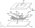
- FIG. 1 is a diagram showing an example of a schematic configuration of a wireless communication device 100 according to a first embodiment of the present invention.
- digital radiography DR is applied as an example of the wireless communication device 100.
- the wireless communication device 100 includes a sensor 110, a fixing member 120, a battery 130, a printed circuit board 140, a coaxial cable 150, an antenna 160, an antenna support member 170, and an exterior housing 180.
- the battery 130 is a mechanism for supplying electric power and is electrically connected to the printed circuit board 140.
- the printed circuit board 140 is equipped with a wireless IC 141, a signal wiring 142, and a connector 143.
- the data signal for wireless communication generated by the wireless IC 141 is transmitted to the antenna 160 via the signal wiring 142, the connector 143, and the coaxial cable 150. Further, the printed circuit board 140 supplies electric power from the battery 130 to the antenna 160 via the coaxial cable 150.
- the coaxial cable 150 is electrically connected to the antenna 160 and supplies the above-mentioned data signal and power for wireless communication to the antenna 160.
- the coaxial cable 150 that supplies this power to the antenna 160 corresponds to a “feeding unit”.
- the antenna 160 includes a first antenna element 161 and a second antenna element 162, and is configured as a dipole antenna.
- the first antenna element 161 and the second antenna element 162 are formed of, for example, a rod-shaped metal.
- the antenna 160 is fixed to the fixing member 120 via the antenna support member 170.
- FIG. 1 also shows an open end portion 161A of the first antenna element 161 and an open end portion 162A of the second antenna element 162.
- one end of the first antenna element 161 and the second antenna element 162 constitutes open end portions 161A and 162A, respectively, and the other end of the first antenna element 161 and the second antenna element.
- a coaxial cable 150 which is a feeding portion, is provided between the other end portion of 162.
- the antenna support member 170 supports the antenna 160 and is fixed to the fixing member 120.
- the fixing member 120 is composed of a conductor, and the positions of the battery 130, the printed circuit board 140, and the antenna support member 170 are fixed on the surface (upper surface).
- the sensor 110 is a component that detects incident radiation, and is arranged (fixed) on the back surface (lower surface) of the fixing member 120.
- the exterior housing 180 is a housing composed of a conductor and including a sensor 110, a fixing member 120, a battery 130, a printed circuit board 140, a coaxial cable 150, an antenna 160, and an antenna support member 170.
- the exterior housing 180 is provided with an opening 181 on one surface 180A for radiating electromagnetic waves from the antenna 160 to the outside of the exterior housing 180.
- the antenna 160 is arranged at a position closer to the opening 181 of the outer housing 180 than the fixing member 120.
- the exterior housing 180 and the fixing member 120 made of a conductor are general metal members such as stainless steel, aluminum, copper, and iron, or resin members having conductivity made of, for example, carbon fiber reinforced plastic. It is formed.
- an opening 181 for radiating electromagnetic waves from the antenna 160 to the outside of the exterior housing 180 is provided in the vicinity of the antenna 160.
- the wireless communication device 100 can perform wireless communication with other wireless communication devices.
- the measurement surface of the SAR value related to the amount of electromagnetic waves absorbed by the human body is one surface 180A of the exterior housing 180 provided with the opening 181, that is, the surface on which the electromagnetic waves can be radiated from the exterior housing 180 and reach the human body. Is.
- the other five surfaces of the outer housing 180 are shielded by metal, and electromagnetic waves do not radiate to the outside of the outer housing 180, so that they do not serve as measurement surfaces for the SAR value.
- the number of measurement surfaces is plurality, and the maximum value among the SAR values measured on the plurality of surfaces is adopted.
- an xyz coordinate system in which the surface (upper surface) of the fixing member is an xz plane related to the x-direction and the z-direction orthogonal to each other and the direction orthogonal to the x-direction and the z-direction is the y-direction is used. It is shown in the figure.
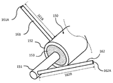
- FIG. 2 is an enlarged view of a region including the coaxial cable 150, the first antenna element 161 and the second antenna element 162.
- the coaxial cable 150 includes a core wire 151, an outer skin conductor 152, and a resin material 153.
- the second antenna element 162 and the core wire 151 are connected (electrically connected), and the first antenna element 161 and the outer skin conductor 152 are connected (electrically connected).
- the dimensions 161B related to the length of the first antenna element 161 and the dimensions 162B related to the length of the second antenna element 162 are dimensions that easily emit radio waves (electromagnetic waves) according to the frequency band used for wireless communication. ing.
- the core wire 151 is connected (electrically connected) to the signal wiring 142 of the printed circuit board 140.
- the outer skin conductor 152 is connected to a ground pattern (not shown) of the printed circuit board 140, and the printed circuit board 140 is electrically connected to the fixing member 120 by a connecting member (not shown).
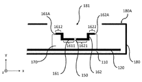
- FIG. 3 is a cross-sectional view of the xy plane of the antenna 160 as viewed from the z direction of FIG.
- the xyz coordinate system shown here corresponds to the xyz coordinate system shown in FIG.
- the same components as those shown in FIGS. 1 and 2 are designated by the same reference numerals, and detailed description thereof will be omitted.
- the antenna elements 161 and 162 are arranged so as to fit within the dimensions of the opening 181.
- the antenna support member 170 is shifted in the x direction, and a part of the antenna elements 161 and 162 is within the dimensions of the opening 181. It may be arranged so that it fits.
- the antenna support member 170 has a stepped shape.
- the coaxial cable 150 which is a power feeding unit, and the first regions 1611 and 1621 located on the side of the coaxial cable 150 of the antenna elements 161 and 162, respectively, are located on the opposite sides of the coaxial cable 150 of the antenna elements 161 and 162, respectively. It is arranged closer to the fixing member 120 than the second regions 1612 and 1622 including the open ends 161A and 162A. Further, the second regions 1612 and 1622 of the antenna elements 161 and 162 are located closer to the opening 181 of the outer housing 180 than the coaxial cable 150 and the first regions 1611 and 1621 of the antenna elements 161 and 162, respectively. It is located in.
- the SAR value related to the amount of electromagnetic waves absorbed by the human body is reduced while suppressing the decrease in the amount of radio wave radiation at the communication frequency. be able to.
- the explanation is described below.
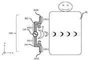
- FIGS. 4A and 4B are image diagrams showing the electromagnetic field distribution of the region near the antenna 160 shown in FIG. 1 and the human body hb.
- FIGS. 4A and 4B illustrate the xyz coordinate system corresponding to the xyz coordinate system shown in FIGS. 1 and 3.
- the electric field E is shown by the crescent-shaped solid line frame
- the magnetic field H is shown by the crescent-shaped dotted line frame.
- FIG. 4A shows the structure of the antenna 160 according to the comparative example.
- the impedance is high, so that the electric field E is mainly generated. It is formed.
- the impedance is low in the vicinity of the connection portion between the antenna elements 161 and 162 and the coaxial cable 150 which is the feeding portion, the magnetic field H is mainly formed.
- FIG. 4B shows the structure of the antenna 160 according to the first embodiment of the present invention. That is, similarly to FIG. 3, the first antenna element 161 having the first region 1611 and the second region 1612, and the second antenna element 162 having the first region 1621 and the second region 1622 are included. It has the structure of the antenna 160.
- the coaxial cable 150 which is a region where the strength of the magnetic field H is particularly strong
- the first region 1611 of the first antenna element 161 and the first region 1621 of the second antenna element 162 are the human body hb. It is arranged so as to keep the distance to.
- FIG. 4B it is assumed that the human body hb exists on the side of the surface 180A of the exterior housing 180 shown in FIG.
- the strength of the magnetic field H in the vicinity of the antenna 160 decreases as the distance increases, so that the strength of the magnetic field H reaching the human body hb decreases.
- the magnetic field H propagates in the horizontal direction with the boundary surface of the human body hb, so that the magnetic field H does not reach the human body hb. Due to these actions, the magnetic field H reaching the interface of the human body hb is significantly reduced, so that the SAR value related to the amount of electromagnetic waves absorbed by the human body can be reduced.
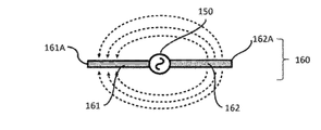
- FIGS. 5A to 5C are image diagrams showing the electric field distribution formed by the antenna 160 shown in FIG.
- the antenna 160 shown in FIGS. 5A and 5B corresponds to the antenna 160 shown in FIG. 4A
- the antenna 160 shown in FIG. 5C corresponds to the antenna 160 shown in FIG. 4B.
- the electric field E has the first antenna element 161 and the second antenna element 162. It is formed like a dotted arrow between them.
- the strength of the electric field E near the open end 161A of the first antenna element 161 and the open end 162A of the second antenna element 162 is the strongest, and the longitudinal direction of the first antenna element 161 and the second antenna element 162 The closer to the coaxial cable 150, which is the feeding portion, along the line, the weaker the strength of the electric field E becomes.
- the fixing member 120 when there is a fixing member 120 made of a conductor having a size larger than that of the antenna 160, the electric field E formed between the first antenna element 161 and the second antenna element 162 is generated. Combines with the fixing member 120. Therefore, the fixing member 120 causes a potential fluctuation. Due to this coupling, radio waves are not radiated into space from the antenna 160, so that the radiation efficiency is lowered.
- the open end portions 161A and the open end portions 161A of the antenna elements 161 and 161 which are regions where the strength of the electric field E emitted from the antenna 160 fixed by the antenna support member 170 is strong.
- 162A has a structure kept away from the fixing member 120 made of a conductor.
- the structure of the antenna 160 in the present embodiment means that the coaxial cable 150, which is a region where the magnetic field H is strong, and the first regions 1611 and 1621 of the antenna elements 161 and 162, respectively, are brought close to the fixing member 120 made of a conductor. It is a structure to arrange.
- FIGS. 6A and 6B are cross-sectional views of the xy plane of the antenna 160 as viewed from the z direction of FIG.
- FIGS. 6A and 6B illustrate the xyz coordinate system corresponding to the xyz coordinate system shown in FIGS. 1 and 3.
- FIGS. 6A and 6B the same components as those shown in FIGS. 1 to 5C are designated by the same reference numerals, and detailed description thereof will be omitted.
- the shape of the antenna 160 including the first antenna element 161 and the second antenna element 162 and the antenna support member 170 shown in FIGS. 6A and 6B can also be adopted.
- FIG. 6A shows a V-shaped portion of the antenna support member 170 on which the first antenna element 161 and the second antenna element 162 (furthermore, the coaxial cable 150) are placed.
- the antenna support member 170 has a coaxial cable 150 which is a feeding portion from one end (open end portions 161A and 162A) of the first antenna element 161 and the second antenna element 162 to the other end portion (feeding portion). Supports up to the end on the side of the antenna in a straight line.
- the portion on which the first antenna element 161 and the second antenna element 162 (furthermore, the coaxial cable 150) are placed has a shape that combines a V shape and a step shape. It is a form.
- the antenna support member 170 is formed from one end (open end 161A and 162A) to the other end (coaxial cable 150 which is a feeding portion) of the first antenna element 161 and the second antenna element 162.
- the antenna elements 161 and 162 are supported in a bent shape up to the end portion on the side of the antenna element 161 and 162.
- the form in which the antenna support member 170 supports the antenna elements 161 and 162 in a bent shape has been described, but for example, a form in which the antenna support member 170 supports the antenna elements 161 and 162 in a curved surface shape may be used. That is, in the present embodiment, the antenna support member 170 may support the antenna elements 161 and 162 in at least one of a bent shape and a curved shape. Further, the number of bends may be one or two or more.
- the first regions 1611 and 1621 of the antenna elements 161 and 162 are regions less than the midpoint in the lengths of the antenna elements 161 and 162, respectively. ing.
- the coaxial cable 150 and the first regions 1611 and 1621 of the antenna elements 161 and 162, which are power feeding units, are respectively connected to the antenna elements 161 and 162, respectively. It is arranged at a position closer to the fixing member 120 composed of the conductor than the second regions 1612 and 1622 including the open ends 161A and 162A of the above. Further, the second regions 1612 and 1622 of the antenna elements 161 and 162 are more external to the electromagnetic waves from the antenna 160 than the coaxial cables 150 and the first regions 1611 and 1621 of the antenna elements 161 and 162, respectively, which are power feeding units. It is arranged at a position close to the opening 181 for radiating to the outside of the housing 180. According to such a configuration, as described with reference to FIGS. 4A to 5C, it is possible to reduce the SAR value related to the amount of electromagnetic waves absorbed by the human body while suppressing the decrease in the amount of radio wave radiation at the communication frequency.
- the antenna 160 is configured by a dipole antenna
- a mode in which an inverted F antenna is applied will be described.
- the schematic configuration of the wireless communication device according to the second embodiment is basically the first embodiment shown in FIG. 1, except for the configuration of the antenna 160 (including the antenna support member 170 that supports the antenna 160). This is the same as the schematic configuration of the wireless communication device 100 according to the above. In the present embodiment, the wireless communication device according to the second embodiment will be described as the wireless communication device 200.
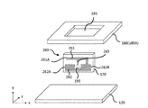
- FIG. 7 shows a second embodiment of the present invention, and is a diagram showing a schematic configuration example when an inverted F antenna supported by an antenna support member 170 is applied as an antenna 260.
- FIG. 7 illustrates the xyz coordinate system corresponding to the xyz coordinate system shown in FIG.
- an antenna 260 supported by an antenna support member 170 made of a flexible printed wiring board is shown.
- the antenna (inverted-F antenna) 260 includes an antenna element 261, a ground conductor portion 262 forming a ground pattern, and a feeder line 263.
- the core wire 151 of the coaxial cable 150 is electrically connected to the feeder line 263, and the outer conductor 152 is electrically connected to the ground conductor portion 262.
- One end of the antenna element 261 constitutes an open end portion 261A, the other end portion is electrically connected to the ground conductor portion 262 and is short-circuited, and a portion between the one end portion and the other end portion is fed. It is a feeder line 263 that is electrically connected to the coaxial cable 150 which is a part.
- FIG. 7 also shows the side end portions 262A and 262B of the ground conductor portion 262.
- FIG. 8 is a diagram showing an example of the electromagnetic field intensity distribution in the vicinity of the antenna (inverted F antenna) 260 shown in FIG.
- the same reference numerals are given to the configurations similar to those shown in FIG. 7, and detailed description thereof will be omitted.
- the dotted line regions 801 and 802 are the regions where the electric field E is the strongest, and the alternate long and short dash line region 803 is the region where the electric field E is the second strongest. Further, the region 804 of the alternate long and short dash line is a region where the magnetic field H is strong.
- FIG. 9 is a diagram showing an example of a schematic configuration of the wireless communication device 200 according to the second embodiment of the present invention.
- the same components as those shown in FIGS. 1 to 8 are designated by the same reference numerals, and detailed description thereof will be omitted. Further, in FIG. 9, only a part of the components of the wireless communication device 200 according to the second embodiment is shown. Further, the xyz coordinate system shown corresponds to the xyz coordinate system shown in FIG.
- the intensity of the magnetic field H that correlates with the intensity of the SAR value related to the amount of electromagnetic waves absorbed by the human body. Therefore, in the present embodiment, as shown in FIG.
- the region near the feeder line 263 included in the region 804 where the magnetic field H is strong is arranged close to the fixing member 120. That is, the coaxial cable 150, which is the feeding portion, and the first region 2611 of the antenna element 261 are arranged at a position closer to the fixing member 120 than the second region 2612 including the open end portion 261A of the antenna element 261.
- the cause of deterioration of the amount of radio wave radiation at the communication frequency is that the fixing member 120 made of the conductor and the antenna 260 are coupled to each other. Therefore, in the present embodiment, as shown in FIG. 9, the region 801 where the electric field E is strong The regions in the vicinity of the open end portion 261A of the antenna element and the side end portions 262A and 262B of the ground conductor portion 262 included in the to 803 are arranged close to the opening 181. That is, the second region 2612 of the antenna element 261 is arranged at a position closer to the opening 181 of the outer housing 180 than the first region 2611 of the coaxial cable 150 and the antenna element 261.
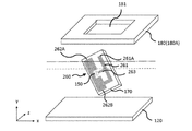
- FIG. 10 is a diagram showing another example of the schematic configuration of the wireless communication device 200 according to the second embodiment of the present invention.
- the same reference numerals are given to the configurations similar to those shown in FIGS. 1 to 9, and detailed description thereof will be omitted.
- FIG. 10 only a part of the components of the wireless communication device 200 according to the second embodiment is shown.
- FIG. 10 illustrates the xyz coordinate system corresponding to the xyz coordinate system shown in FIGS. 1 and 9.
- the feeder line 263 is a fixing member 120 made of a conductor rather than the open end portion 261A of the antenna element 261 and the side end portion 262A of the ground conductor portion 262 closer to the open end portion 261A.
- the antenna support member 170 is tilted and arranged so as to approach. That is, the dotted line shown in FIG.
- FIGS. 11A and 11B are diagrams showing other examples of the schematic configuration of the wireless communication device 200 according to the second embodiment of the present invention.
- FIGS. 11A and 11B the same components as those shown in FIGS. 1 to 10 are designated by the same reference numerals, and detailed description thereof will be omitted.
- FIGS. 11A and 11B only a part of the components of the wireless communication device 200 according to the second embodiment is shown.
- FIGS. 11A and 11B illustrate the xyz coordinate system corresponding to the xyz coordinate system shown in FIGS. 1, 9 and 10.
- the fixing member 120, the antenna 260, and the opening 181 are arranged in order in the y direction, and the antenna 260 is arranged so that the xz plane of FIG. 7 and the xz plane of FIG. 9 face the same plane.
- the present embodiment is not limited to this.
- FIG. 11A a form in which the xz surface of FIG. 7 and the xy surface of FIG. 11A face the same surface, that is, a form in which the antenna element 261 is arranged in the direction perpendicular to the surface of the fixing member 120 is also conceivable.
- FIG. 11B the form in which the antenna element 261 is arranged at an angle with respect to the surface of the fixing member 120 is applicable to the present embodiment.
- the antenna support member 170 has a form in which the antenna element 261 and the ground conductor portion 262 are supported in a plane shape. Further, in the example shown in FIG. 9, the antenna support member 170 is in a form of supporting the antenna element 261 and the ground conductor portion 262 in a bent shape. In the example shown in FIG. 9, the form in which the antenna support member 170 supports the antenna element 261 and the ground conductor portion 262 in a bent shape has been described, but the antenna support member 170 may be supported in a curved surface shape, for example. That is, in the present embodiment, the antenna support member 170 may support the antenna element 261 and the ground conductor portion 262 in at least one of a bent shape and a curved shape. Further, the number of bends may be one or two or more.
- the wireless communication device 200 according to the second embodiment also adopts the same configuration as the wireless communication device 100 according to the first embodiment. That is, the position where the first region 2611 of the coaxial cable 150 and the antenna element 261 which is the feeding portion is closer to the fixing member 120 composed of the conductor than the second region 2612 including the open end portion 261A of the antenna element 261. I try to place it in. Further, the opening 181 for radiating the electromagnetic wave from the antenna 260 to the outside of the outer housing 180 from the second region 2612 of the antenna element 261 from the coaxial cable 150 which is the feeding portion and the first region 2611 of the antenna element 261. I try to place it in a position close to. According to such a configuration, it is possible to reduce the SAR value related to the amount of electromagnetic waves absorbed by the human body while suppressing the decrease in the amount of radio wave radiation at the communication frequency, as in the first embodiment described above.
- the antenna 160 is configured by a dipole antenna
- a mode in which the inverted F antenna is applied will be described as in the second embodiment.
- the schematic configuration of the wireless communication device according to the third embodiment is basically a schematic configuration of the wireless communication device 100 according to the first embodiment shown in FIG. 1, except for the configuration of the antenna 160 and the antenna support member 170. Similar to the configuration.
- the wireless communication device according to the third embodiment will be described as the wireless communication device 300.
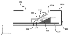
- FIG. 12 is a diagram showing an example of a schematic configuration of the wireless communication device 300 according to the third embodiment of the present invention.
- the same reference numerals are given to the configurations similar to those shown in FIGS. 1 to 11B, and detailed description thereof will be omitted.
- FIG. 12 only a part of the components of the wireless communication device 300 according to the third embodiment is shown.
- FIG. 12 illustrates the xyz coordinate system corresponding to the xyz coordinate system shown in FIGS. 1 and 3.
- the antenna 360 is an inverted F antenna with the fixing member 120 made of a conductor as the ground.
- the antenna (inverted-F antenna) 360 includes an antenna element 361, a feeder line (conductive portion) 362 made of a conductor, and a convex protrusion 363 made of a conductor.
- the protrusion 363 is provided between the antenna element 361 and the fixing member 120.
- such a protrusion 363 may be applied to a dipole antenna, a monopole antenna, and an inverted L antenna.
- One end of the antenna element 361 constitutes an open end 361A, the other end of the antenna element 361 is electrically connected to a fixing member 120 made of a conductor serving as a ground, and one end and the other end of the antenna element 361 are electrically connected.
- a feeder line 362 is provided between the two.
- a protrusion 363 made of a conductor is provided on the fixing member 120 made of a conductor, and the dotted line passing through a part of the feeder line 362 is more conductive than the alternate long and short dash line passing through the protrusion 363 serving as the ground. It is arranged close to the fixing member 120 made of the body.
- the coaxial cable 150 which is the feeding portion and the first region 3611 of the antenna element 361 are located closer to the fixing member 120 than the second region 3612 including the open end portion 361A of the antenna element 361. Place in. Further, the second region 3612 of the antenna element 361 is arranged at a position closer to the opening 181 of the outer housing 180 than the first region 3611 of the coaxial cable 150 and the antenna element 361. According to such a configuration, it is possible to reduce the SAR value related to the amount of electromagnetic waves absorbed by the human body while suppressing the decrease in the amount of radio wave radiation at the communication frequency, as in the first and second embodiments described above.
- 13A to 13D are diagrams showing an example of a schematic configuration of the wireless communication device 400 according to the fourth embodiment of the present invention.
- 13A to 13D show only a part of the components of the wireless communication device 400 according to the fourth embodiment.
- the xyz coordinate system shown here corresponds to the xyz coordinate system shown in FIG.
- the wireless communication device 400 includes a fixing member 420 corresponding to the fixing member 120 of FIG. 1, a coaxial cable 450 corresponding to the coaxial cable 150 of FIG. 1, and an antenna 460 corresponding to the antenna 160 of FIG. It is configured to have an antenna support member 470 corresponding to the antenna support member 170 of FIG. 1 and an exterior housing 480 corresponding to the exterior housing 180 of FIG.
- the wireless communication device 400 according to the fourth embodiment is also configured to further include components corresponding to the sensor 110, the battery 130, and the printed circuit board 140 shown in FIG.
- the exterior housing 180 is provided with openings 481, 482 and 483 on the surface 480A, and is provided with openings 484 on the surface 480B.
- FIG. 13B shows a cross-sectional view of xz in FIG. 13A
- FIG. 13C shows a cross-sectional view of xy in FIG. 13A
- FIG. 13D shows a cross-sectional view of yz in FIG. 13A.
- FIG. 13A when viewed from the direction perpendicular to the opening surface of the opening 483 (y direction), at least a part of the antenna 460 overlaps with the opening 483 as shown in FIG. 13B.
- the antenna 460 shown in FIG. 13A is a dipole antenna, and includes a first antenna element 461 and a second antenna element 462.
- the antenna 460 is adhesively fixed to the stepped antenna support member 470.
- the antenna support member 470 is adhesively fixed to the fixing member 420 made of a conductor.
- the exterior housing 480 made of a conductor is fixed to a fixing member 420 made of a conductor, and the surfaces 480A of the exterior housing 480 made of a conductor are provided with openings 481, 482, and 483 shown by alternate long and short dash lines. ing.
- the surface 480B of the outer housing 480 made of a conductor is provided with openings 484 indicated by alternate long and short dash lines, and each opening is filled with a resin member.
- the openings 483 and 484 provided in the vicinity of the antenna 460 are provided to radiate the electromagnetic waves emitted by the antenna 460 to the outside of the outer housing 480, and the openings 483 are located closest to the antenna 460. It is an opening provided in. Further, since the sensor 110 for detecting radiation has a low influence on the fixing member 120 made of a conductor on the back surface side of the antenna 460, the illustration is omitted.
- Table 1 below shows the dimensions illustrated in FIGS. 13B, 13C, 13D and 16.
- FIG. 14 is a diagram showing an example of the conductor pattern of the antenna 460 shown in FIG. 13A.
- the antenna 460 a 2.4 / 5 GHz dual band flexible antenna (146153 series) manufactured by Molex was used. Since the antenna 460 is formed by bending the first antenna element 461 and the second antenna element 462 for miniaturization, the open ends 1401A and 1402A of the antenna elements 461 and 462, respectively, are the antenna 460. It faces the center side of. Further, the antenna 460 has a shape that efficiently radiates radio waves in the 2 GHz band and the 5 GHz band in order to correspond to the Wifi communication frequency band.
- a coaxial cable 450 which is a feeding portion, is connected between the side end portion 1401B of the first antenna element 461 and the side end portion 1402B of the second antenna element 462.
- the conductor pattern dimensions of the antenna 460 were measured, and the calculation was performed using the MW-STUDIO of the electromagnetic field simulator manufactured by AET. ..
- FIGS. 15A and 15B are diagrams showing the intensity distributions of the magnetic field H and the electric field E calculated using the antenna 460 shown in FIG.
- the same components as those shown in FIG. 14 are designated by the same reference numerals, and detailed description thereof will be omitted.
- FIG. 15A shows a region where the magnetic field H of the antenna 460 is strong
- FIG. 15B shows a region where the electric field E is strong.
- the observation frequencies were 2.4 GHz and 5.3 GHz.
- the region where the magnetic field is strong shown in FIG. 15A is almost the same at 2.4 GHz and 5.3 GHz
- the region 1501 where the magnetic field is strongest is the feeding point to which the coaxial cable 450 is connected, as shown by the dotted line in FIG. 15A. That is, it is a region including the side end portions 1401B and 1402B.
- the regions 1502 and 1503 having the second strongest magnetic field are the regions adjacent to the feeding point as shown by the alternate long and short dash line in FIG.
- the regions 1504 and 1505 having the third strongest magnetic field are the two points in FIG. 15A. As shown by the chain line, it is a region between the open end portions 1401A and 1402A and the feeding point in the antenna elements 461 and 462.
- the strength of the magnetic field H is not uniform in these regions, and the strength becomes weaker as it approaches the open ends 1401A and 1402A of the antenna.
- the regions 1511-1513 and 1521-1523 where the electric field E is strong shown in FIG. 15B are the open ends 1401A and 1402A of the antenna elements 461 and 462 and the antenna 460 at a frequency of 2.4 GHz, as shown by the dotted line in FIG. 15B. It is a region of the side ends 1401C and 1402C in the longitudinal direction in the outer shape and the side ends 1401F and 1402F between them. Further, the regions 1514 and 1524 having a strong electric field at 5.3 GHz are the regions of the open ends 1401A and 1402A of the antenna elements 461 and 462 and the side end 1401D of the antenna element 461, as shown by the alternate long and short dash line in FIG. 15B.
- the antenna support member 470 is made of a dielectric in order to arrange the above-mentioned region having a strong magnetic field H close to the fixing member 420 made of a conductor and the above-mentioned region having a strong electric field E close to the opening 483. It was a stepped member.
- FIG. 16 is a diagram showing an example of the dimensions of the conductor pattern of the antenna 460 shown in FIG.
- the same reference numerals are given to the configurations similar to those shown in FIGS. 14 to 15B, and detailed description thereof will be omitted.
- the shortest distance from the fixing member 420 to the antenna 460 was set to 2.8 mm.
- the shape is such that the shortest distance from the fixing member 420 to the antenna 460 has a dimension of 4.8 mm.
- the antenna support member whose shortest distance from the fixing member 420 made of a conductor to the antenna element 461 is constant at 2.8 mm, 3.8 mm, and 4.8 mm without a step. 470 was calculated and compared with the results of this embodiment.
- the SAR value a human body phantom having a size larger than the outer shape of the DR of 594 x 520 x 46 [mm] was placed in close contact with the surfaces 480A and 480B.
- the material constant of the solvent of the human body phantom used in the international standard measurement is used, the conductivity ⁇ is 2 [S / m], the relative permittivity is 52.21, Tan ⁇ is 0.28, and the substance.
- the density ⁇ was 1000.
- the conductor of the fixing member 420 or the like was made of stainless steel, and its conductivity ⁇ was 110000 [S / m].
- the communication characteristics were calculated with the human phantom removed, and the radiation efficiency was calculated.
- the radiation efficiency the ratio of the power supplied to the signal line at the communication frequency to the total power of the radiated electromagnetic wave passing through a point 1 [m] away from the antenna 460 was calculated.
- Table 2 shows the results of calculating the SAR value and the radiation efficiency.
- the SAR value decreases as the distance from the fixing member 420 to the antenna 460 decreases, and the SAR value of 2.8 mm constant decreases. It is the lowest.
- the value of radiation efficiency the value of radiation efficiency becomes higher as it approaches the opening, and the radiation efficiency of 4.8 mm is the best.
- the amount of radio wave radiation and the SAR value can be balanced by keeping the thickness 3.8 mm constant. Comparing the step shape of the present embodiment with the constant 3.8 mm, the value of the radiation efficiency was improved by 2.4 GHz as compared with the constant step shape of 3.8 mm, but slightly deteriorated by 5.5 GHz.
- the SAR value is reduced at 2.4 GHz and 5.5 GHz. That is, according to the structure of the present embodiment, it is possible to reduce the SAR value related to the amount of electromagnetic waves absorbed by the human body while suppressing the decrease in the amount of radio wave radiation at the communication frequency.
- FIG. 17 is a diagram showing an example of the conductor pattern of the antenna 460 shown in FIG.
- the dotted lines 1701 and 1702 are the midpoints of the widths of the antenna elements 461 and 462 drawn along the antenna elements.
- the antenna element length of the first antenna element 461 has a dimension of 32.6 [mm] from the side end portion 1401B to the open end portion 1401A.
- the antenna element length of the second antenna element 462 has a dimension of 36.95 [mm] from the side end portion 1402B to the open end portion 1402A.
- the points P1 and P2 are the ends of the dimension W1 in Table 1, and the distance from the side end 1401B to the point P1 is 14.015 [mm].
- the distance from the side end 1402B to the point P2 is 18.315 [mm]. That is, in the first antenna element 461, 43.0% of the total length 1701 of the antenna element is arranged close to the conductor from the feeding portion. Further, in the second antenna element 462, 49.6% of the total length 1702 of the antenna element is arranged close to the conductor from the feeding portion.
- the effect of the present embodiment is achieved by bringing the region from the feeding portion to the point approximately 50% of the total length of the antenna elements 461 and 462, that is, the intermediate point of the antenna element length, closer to the fixing member 420 made of the conductor. Is obtained.
- FIG. 18A and 18B are diagrams showing an example of a component corresponding to the antenna 460 and the antenna support member 470 shown in FIG. 13A. Similar effects were obtained when the V-shaped antenna support member 470 was applied instead of the stepped antenna support member 470 shown in FIG. 13A, as shown in FIG. 18A.
- the dimension of 49.5% of the difference between the longest distance r of the antenna elements 461 and 462 and the shortest distance s of the antenna elements 461 and 462 from the fixing member 420 is arranged close to the shortest distance s.
- the distance W4 from the fixed member 420 of the points P1 and P2 is less than half the difference between the longest distance r and the shortest distance s from the fixed member 420 to the antenna elements 461 and 462, and the shortest distance s.
- the antenna elements 461 and 462 are arranged so as to be less than the sum of the dimensions.
- the antenna elements 461 and 462 are arranged so that the dimension of less than half of the difference between the longest distance and the shortest distance from the fixing member 420 to the antenna elements 461 and 462 is close to the shortest distance.
- the wireless communication device 400 according to the fourth embodiment also adopts the same configuration as the wireless communication device 100 in the first embodiment. That is, as shown in FIGS. 18A and 18B, the first regions 4611 and 4621 of the coaxial cable 150 and the antenna elements 461 and 462, which are power feeding portions, are divided into the second regions 4612 and 4622 of the antenna elements 461 and 462, respectively. Rather, it is arranged at a position closer to the fixing member 120 composed of the conductor. According to such a configuration, it is possible to reduce the SAR value related to the amount of electromagnetic waves absorbed by the human body while suppressing the decrease in the amount of radio wave radiation at the communication frequency, as in the first embodiment.
- a dipole antenna or an inverted F antenna is applied as the antenna, but the present invention is not limited to this, and a so-called inverted L antenna or a monopole antenna can also be applied.
- the antenna is configured to further include a ground conductor portion (or a conductive portion made of a conductor) used as a ground of the antenna element in addition to the antenna element, and the antenna element is configured. One end thereof constitutes an open end portion, and a feeding portion is provided between the other end portion and the ground conductor portion (or the above-mentioned conductive portion).
- the antenna when an inverted L antenna is applied, is configured to further include a ground conductor portion (or a conductive portion made of a conductor) used as a ground of the antenna element in addition to the antenna element, and the antenna element.
- a ground conductor portion or a conductive portion made of a conductor
- the present invention is applied to DR as a wireless communication device is shown, but it may be applied to a camera or the like having a wireless communication function.
- Wireless communication device 110: Sensor, 120: Fixing member, 130: Battery, 140: Printed circuit board, 141: Wireless IC, 142: Signal wiring, 143: Connector, 150: Coaxial cable, 160: Antenna, 161: No. 1 antenna element, 162: 2nd antenna element, 170: antenna support member, 180: exterior housing, 181: opening
Landscapes
- Engineering & Computer Science (AREA)
- Computer Networks & Wireless Communication (AREA)
- Details Of Aerials (AREA)
- Support Of Aerials (AREA)
Abstract
本発明に係る無線通信装置において、アンテナ素子を含み構成されているアンテナは、導電体から構成され、アンテナを固定するための固定部材よりも外装筐体の開口に近い位置に配置されており、アンテナに電力を供給する給電部及びアンテナ素子の給電部の側に位置する第1領域は、アンテナ素子の開放端部を含む第2領域よりも、固定部材に近い位置に配置されている。
Description
本発明は、アンテナからの電磁波を外部に放射させる無線通信装置に関するものである。
近年の電子機器には、無線通信機能が標準搭載されている。例えば、放射線の照射によって人体(生体)の内部の臓器を可視化しうるデジタルラジオグラフィー(DR)では、無線LANやBluetooth(登録商標)等により、他のPCからの撮影動作等の遠隔操作や撮影画像をPCに伝送することが可能になっている。
無線通信装置では、導電体から構成された部品(部材)が無線アンテナの近傍に配置されると、通信周波数での電波放射量が低下するという問題がある。DRは、小型・薄型化と落下衝撃に対する耐性を高めるため、通常、アンテナの近傍に開口を有する金属製の外装筐体によって囲まれている。また、アンテナの近傍には、板状の導電部材が配置されている。この導電部材は、アンテナを固定するための固定部材として用いられる。DRにおいても、上述した構造によって、通信周波数での電波放射量が著しく減少する問題があった。
このような電波放射量の減少を防ぐ手段の1つとして、例えば、非特許文献1に記載されているように、アンテナに供給する電力を上げることで放射電力の劣化分を補い、通信周波数での電波放射量を高める方法が知られている。
羽鳥光俊 監修「EMC設計の実際」丸善出版事業部(平成12年6月30日発行、P.238)
一般に、無線通信装置において、アンテナが発する高出力の電磁波が人体に侵入してそのエネルギーが人体に吸収されると、局所的に人体の温度が上昇することが知られている。そして、この人体の局所的な温度上昇により、例えば白内障等の発症リスクが高まる可能性が指摘されている。そのため、各国では、電磁波の人体吸収量をSAR(Specific Absorption Ratio)値として、その規制値を定めている。従来の技術においては、通信周波数での電波放射量の減少を防ぐためにアンテナの給電電力を上げると、SAR値が規制値以上になることがあるという問題が生じていた。
本発明は、このような問題点に鑑みてなされたものであり、電波放射量の減少を抑制しつつ、SAR値を低減できる無線通信装置を提供することを目的とする。
本発明の無線通信装置は、アンテナ素子を含み構成されているアンテナと、導電体から構成され、前記アンテナを固定するための固定部材と、前記アンテナに電気的に接続され、前記アンテナに電力を供給する給電部と、導電体から構成され、前記アンテナ、前記固定部材および前記給電部を内包する外装筐体であって、前記アンテナからの電磁波を当該外装筐体の外部に放射させるための開口を備える外装筐体と、を有し、前記アンテナは、前記固定部材よりも前記外装筐体の前記開口に近い位置に配置されており、前記給電部および前記アンテナ素子の前記給電部の側に位置する第1領域は、前記アンテナ素子の前記給電部とは反対側に位置する開放端部を含む第2領域よりも、前記固定部材に近い位置に配置されている。
本発明のさらなる特徴が、添付の図面を参照して以下の例示的な実施形態の説明から明らかになる。
以下に、図面を参照しながら、本発明を実施するための形態(実施形態)について説明する。
(第1の実施形態)
図1は、本発明の第1の実施形態に係る無線通信装置100の概略構成の一例を示す図である。ここで、本実施形態では、無線通信装置100の一例として、デジタルラジオグラフィー(DR)を適用する。
図1は、本発明の第1の実施形態に係る無線通信装置100の概略構成の一例を示す図である。ここで、本実施形態では、無線通信装置100の一例として、デジタルラジオグラフィー(DR)を適用する。
無線通信装置100は、センサ110、固定部材120、バッテリー130、プリント基板140、同軸ケーブル150、アンテナ160、アンテナ支持部材170、及び、外装筐体180を有して構成されている。
バッテリー130は、電力を供給する機構であり、プリント基板140と電気的に接続されている。
プリント基板140は、無線IC141、信号配線142及びコネクタ143を搭載している。無線IC141で生成された無線通信用のデータ信号は、信号配線142、コネクタ143及び同軸ケーブル150を介して、アンテナ160に伝送される。また、プリント基板140は、同軸ケーブル150を介して、バッテリー130からの電力をアンテナ160に供給する。
同軸ケーブル150は、アンテナ160に電気的に接続され、アンテナ160に対して上述した無線通信用のデータ信号や電力を供給する。この電力をアンテナ160に供給する同軸ケーブル150は、「給電部」に相当する。
アンテナ160は、第1のアンテナ素子161及び第2のアンテナ素子162を含み構成されており、ダイポールアンテナとして構成されている。ここで、第1のアンテナ素子161及び第2のアンテナ素子162は、例えば、棒状の金属で形成されている。このアンテナ160は、アンテナ支持部材170を介して固定部材120に固定されている。また、図1では、第1のアンテナ素子161の開放端部161A、及び、第2のアンテナ素子162の開放端部162Aも示している。ここで、第1のアンテナ素子161及び第2のアンテナ素子162は、それぞれ、その一端部が開放端部161A及び162Aを構成し、第1のアンテナ素子161の他端部と第2のアンテナ素子162の他端部との間に給電部である同軸ケーブル150が設けられている。
アンテナ支持部材170は、アンテナ160を支持し、固定部材120に固定される。
固定部材120は、導電体から構成され、バッテリー130、プリント基板140及びアンテナ支持部材170の位置を表面(上面)で固定している。
センサ110は、入射した放射線を検出する構成部であり、固定部材120の裏面(下面)に配置(固定)されている。
外装筐体180は、導電体から構成され、センサ110、固定部材120、バッテリー130、プリント基板140、同軸ケーブル150、アンテナ160及びアンテナ支持部材170を内包する筐体である。この外装筐体180は、1つの面180Aに、アンテナ160からの電磁波を外装筐体180の外部に放射させるための開口181を備えている。この際、アンテナ160は、固定部材120よりも外装筐体180の開口181に近い位置に配置されている。
ここで、導電体から構成されている外装筐体180及び固定部材120は、ステンレス、アルミ、銅、鉄といった一般的な金属部材、または、例えば炭素繊維強化プラスチックからなる導電率を有する樹脂部材で形成されている。この外装筐体180において、アンテナ160の近傍には、アンテナ160からの電磁波を外装筐体180の外部に放射させるための開口181が設けられている。この構成により、無線通信装置100は、他の無線通信装置との無線通信が可能である。この構造において、電磁波の人体吸収量に係るSAR値の測定面は、開口181が設けられた外装筐体180の1つの面180A、即ち電磁波が外装筐体180から放射され人体に到達しうる面である。外装筐体180のそれ以外の5つの面は、金属で遮蔽され、電磁波が外装筐体180の外部に放射しないので、SAR値の測定面とはならない。但し、面180A以外の面に開口がある場合、測定面は複数となり、複数の面で測定したSAR値の中の最大値が採用される。
なお、図1では、例えば、固定部材の表面(上面)を、相互に直交するx方向及びz方向に係るxz平面とし、x方向及びz方向に直交する方向をy方向としたxyz座標系を図示している。
図2は、同軸ケーブル150、第1のアンテナ素子161及び第2のアンテナ素子162を含む領域の拡大図である。
同軸ケーブル150は、芯線151、外皮導体152及び樹脂材153を含み構成されている。第2のアンテナ素子162と芯線151とが接続(電気的に接続)され、第1のアンテナ素子161と外皮導体152とが接続(電気的に接続)されている。第1のアンテナ素子161の長さに係る寸法161B及び第2のアンテナ素子162の長さに係る寸法162Bは、無線通信で利用する周波数帯域に合わせて電波(電磁波)が放射しやすい寸法となっている。なお、芯線151は、プリント基板140の信号配線142と接続(電気的に接続)されている。外皮導体152は、プリント基板140の不図示のグラウンドパターンに接続され、プリント基板140は、不図示の接続部材によって固定部材120に電気的に接続されている。
図3は、図1のz方向から見たアンテナ160でのxy平面に係る断面図である。ここで示されているxyz座標系は、図1に示すxyz座標系に対応している。図1及び図2に示す構成と同様の構成については、同じ符号を付しており、その詳細な説明は省略する。
なお、アンテナ素子161、162が開口181の寸法内に収まるように配置されているが、例えば、アンテナ支持部材170をx方向にずらし、アンテナ素子161及び162の一部が開口181の寸法内に収まるように配置してもよい。
アンテナ支持部材170は、段差形状をしている。給電部である同軸ケーブル150、並びに、アンテナ素子161及び162の同軸ケーブル150の側にそれぞれ位置する第1領域1611及び1621は、アンテナ素子161及び162の同軸ケーブル150とは反対側にそれぞれ位置する開放端部161A及び162Aを含む第2領域1612及び1622よりも、固定部材120に近い位置に配置されている。また、アンテナ素子161及び162のそれぞれの第2領域1612及び1622は、同軸ケーブル150、並びにアンテナ素子161及び162のそれぞれの第1領域1611及び1621よりも、外装筐体180の開口181に近い位置に配置されている。第1のアンテナ素子161及び第2のアンテナ素子162を含むアンテナ160がこの構造を採ることによって、通信周波数における電波放射量の減少を抑制しつつ、電磁波の人体吸収量に係るSAR値を低減することができる。以下にその説明を記載する。
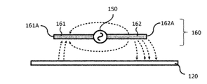
図4A及び図4Bは、図1に示すアンテナ160の近傍領域及び人体hbの電磁界分布を示すイメージ図である。ここで、図4A及び図4Bには、図1及び図3に示すxyz座標系に対応するxyz座標系を図示している。また、図4Aにおいて、三日月状の実線枠で電界Eを示し、三日月状の点線枠で磁界Hを示している。
図4Aは、比較例に係るアンテナ160の構造を示しており、アンテナ160の近傍において、アンテナ素子161及び162のそれぞれの開放端部161A及び162Aの付近では、インピーダンスが高いので主に電界Eが形成される。また、アンテナ素子161及び162と給電部である同軸ケーブル150との接続部付近では、インピーダンスが低いので主に磁界Hが形成される。アンテナ160と人体hbとが近づくと、図4Aに示すように、アンテナ160の近傍の電界Eは、人体hbの内部へ伝搬せず、磁界Hのみが人体hbの内部へ伝搬する。これは、人体hbの比誘電率が約50程度と高く、電束Dが連続となる人体hbと空気との境界面において、D=εEの式で考えると、電界Eが約1/50と急激に減衰するからである。また、人体hbの比透磁率は1と空気中と同じであり、磁束Bが連続となる人体hbと空気との境界面において、B=μHの式で考えると、磁界Hは減衰しないからである。また、人体hbの内部へ伝搬した磁界Hは、波長λ=c/(f×√ε)の式で求められる波長短縮によって、電磁波として電界E・磁界Hと人体hbの内部を伝搬していく。波長短縮の例として、周波数f=5[GHz]の場合の波長は、光速c=3×108[m/s]として計算すると、空気中では60[mm]であるのに対して、人体hbの内部では8.3[mm]と波長が短くなる。以上のことから、電磁波の人体吸収量に係るSAR値の強度と相関があるのは、アンテナ160の近傍の磁界Hの強度である。
図4Bは、本発明の第1の実施形態に係るアンテナ160の構造を示している。即ち、図3と同様に、第1領域1611及び第2領域1612を有する第1のアンテナ素子161、並びに、第1領域1621及び第2領域1622を有する第2のアンテナ素子162を含み構成されたアンテナ160の構造となっている。具体的に、図4Bでは、特に磁界Hの強度の強い領域となる同軸ケーブル150、並びに第1のアンテナ素子161の第1領域1611及び第2のアンテナ素子162の第1領域1621が、人体hbまでの距離を遠ざけるように配置されている。なお、図4Bでは、図1に示す外装筐体180の面180Aの側に人体hbが存在する場合を想定している。ここで、アンテナ160の近傍の磁界Hは、距離が遠ざかる程強度が減衰するので、人体hbに到達する磁界Hの強度は減少する。また、アンテナ素子161及び162において直角に折り曲げられた領域では、図4Bに示すように、人体hbの境界面と水平方向に磁界Hが伝搬するため、人体hbに到達しない。これらの作用により、人体hbの境界面に到達する磁界Hが大幅に減少することから、電磁波の人体吸収量に係るSAR値を低減することができる。
図5A乃至図5Cは、図1に示すアンテナ160によって形成される電界分布を示すイメージ図である。ここで、図5A及び図5Bに示すアンテナ160は、図4Aに示すアンテナ160に相当し、図5Cに示すアンテナ160は、図4Bに示すアンテナ160に相当する。
図5Aに示すように、例えば、第1のアンテナ素子161がマイナス電荷の場合、第2のアンテナ素子162はプラス電荷となり、電界Eは、第1のアンテナ素子161と第2のアンテナ素子162との間で点線の矢印のように形成される。第1のアンテナ素子161の開放端部161A及び第2のアンテナ素子162の開放端部162Aの付近の電界Eの強度が最も強く、第1のアンテナ素子161及び第2のアンテナ素子162の長手方向に沿って給電部である同軸ケーブル150に近づく程、電界Eの強度が弱くなる。
また、図5Bに示すように、アンテナ160よりも大きいサイズの導電体からなる固定部材120がある場合、第1のアンテナ素子161と第2のアンテナ素子162との間で形成される電界Eが固定部材120と結合する。このため、固定部材120が電位変動を起こす。この結合によって、アンテナ160から電波が空間に放射されなくなるため、放射効率が低下する。
図5Cに示すように、本実施形態のアンテナ160の構造では、アンテナ支持部材170で固定されたアンテナ160から発せられる電界Eの強度の強い領域となるアンテナ素子161及び161の開放端部161A及び162Aが、導電体からなる固定部材120から遠ざけられた構造となっている。これにより、図5Bを用いて説明した電界Eの固定部材120との結合を極力抑えることができ、その結果、通信周波数における電波放射量の減少を抑制することができる(図5Bの場合と比較して、通信周波数における電波放射量を高めることができる)。
図4A乃至図5Cを用いて説明したように、本実施形態では、図4B及び図5Cに示すアンテナ160の構造を採ることにより、通信周波数における電波放射量の減少を抑制しつつ、電磁波の人体吸収量に係るSAR値を低減することができる。ここで、本実施形態におけるアンテナ160の構造とは、磁界Hの強い領域である同軸ケーブル150とアンテナ素子161及び162のそれぞれの第1領域1611及び1621を導電体からなる固定部材120に近づけて配置する構造である。
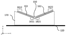
図6A及び図6Bは、図1のz方向から見たアンテナ160でのxy平面に係る断面図である。ここで、図6A及び図6Bには、図1及び図3に示すxyz座標系に対応するxyz座標系を図示している。この図6A及び図6Bにおいて、図1乃至図5Cに示す構成と同様の構成については同じ符号を付しており、その詳細な説明は省略する。
本実施形態においては、図6A及び図6Bに示す、第1のアンテナ素子161及び第2のアンテナ素子162を含み構成されているアンテナ160、並びに、アンテナ支持部材170の形状も採りうる。
図6Aは、アンテナ支持部材170において、第1のアンテナ素子161及び第2のアンテナ素子162(更には、同軸ケーブル150)を載置する部分をVの字形状とした形態である。この図6Aに示す形態では、アンテナ支持部材170は、第1のアンテナ素子161及び第2のアンテナ素子162の一端部(開放端部161A及び162A)から他端部(給電部である同軸ケーブル150の側の端部)までを直線状に支持する。
図6Bは、アンテナ支持部材170において、第1のアンテナ素子161及び第2のアンテナ素子162(更には、同軸ケーブル150)を載置する部分をVの字形状と段差形状を組み合わせた形状とした形態である。この図6Bに示す形態では、アンテナ支持部材170は、第1のアンテナ素子161及び第2のアンテナ素子162の一端部(開放端部161A及び162A)から他端部(給電部である同軸ケーブル150の側の端部)までの間で、アンテナ素子161及び162を折れ曲がり状で支持する。なお、本実施形態においては、アンテナ支持部材170が、アンテナ素子161及び162を折れ曲がり状で支持する形態を説明したが、例えば、曲面状で支持する形態であってもよい。即ち、本実施形態においては、アンテナ支持部材170は、アンテナ素子161及び162を折れ曲がり状及び曲面状のうちの少なくとも一方で支持する形態であればよい。また、折れ曲がりは、1か所または2か所以上でもよい。
また、図6B(図6Aも含みうる)に示す例では、アンテナ素子161及び162のそれぞれの第1領域1611及び1621は、それぞれのアンテナ素子161及び162の長さにおける中間点未満の領域となっている。
以上説明したように、第1の実施形態に係る無線通信装置100では、給電部である同軸ケーブル150及びアンテナ素子161及び162のそれぞれの第1領域1611及び1621を、アンテナ素子161及び162のそれぞれの開放端部161A及び162Aを含む第2領域1612及び1622よりも、導電体から構成されている固定部材120に近い位置に配置するようにしている。また、アンテナ素子161及び162のそれぞれの第2領域1612及び1622を、給電部である同軸ケーブル150及びアンテナ素子161及び162のそれぞれの第1領域1611及び1621よりも、アンテナ160からの電磁波を外装筐体180の外部に放射させるための開口181に近い位置に配置するようにしている。かかる構成によれば、図4A乃至図5Cを用いて説明したように、通信周波数における電波放射量の減少を抑制しつつ、電磁波の人体吸収量に係るSAR値を低減することができる。
(第2の実施形態)
以下の第2の実施形態の説明では、第1の実施形態と共通する事項については説明を省略し、第1の実施形態と異なる事項について説明を行う。
以下の第2の実施形態の説明では、第1の実施形態と共通する事項については説明を省略し、第1の実施形態と異なる事項について説明を行う。
第1の実施形態では、アンテナ160をダイポールアンテナで構成する例について説明をしたが、第2の実施形態では、逆Fアンテナを適用する形態について説明する。
第2の実施形態に係る無線通信装置の概略構成は、アンテナ160(アンテナ160を支持するアンテナ支持部材170も含む)の構成以外については、基本的には、図1に示す第1の実施形態に係る無線通信装置100の概略構成と同様である。本実施形態においては、第2の実施形態に係る無線通信装置を、無線通信装置200として説明する。
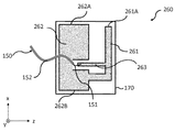
図7は、本発明の第2の実施形態を示し、アンテナ260としてアンテナ支持部材170で支持された逆Fアンテナを適用した場合の概略構成例を示す図である。ここで、図7には、図1に示すxyz座標系に対応するxyz座標系を図示している。図7に示す例では、フレキシブルプリント配線板からなるアンテナ支持部材170で支持されたアンテナ260を示している。
図7に示すように、アンテナ(逆Fアンテナ)260は、アンテナ素子261、グラウンドパターンを構成するグラウンド導体部262、及び、給電線263を含み構成されている。同軸ケーブル150の芯線151が給電線263に電気的に接続され、外皮導体152がグラウンド導体部262に電気的に接続されている。アンテナ素子261は、その一端部が開放端部261Aを構成し、その他端部がグラウンド導体部262に電気的に接続されて短絡され、当該一端部と当該他端部との間の部分が給電部である同軸ケーブル150と電気的に接続される給電線263となっている。また、図7は、グラウンド導体部262の側端部262A及び262Bも図示している。
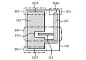
図8は、図7に示すアンテナ(逆Fアンテナ)260の近傍における電磁界強度分布の一例を示す図である。この図8において、図7に示す構成と同様の構成については同じ符号を付しており、その詳細な説明は省略する。
図8において、点線の領域801及び802は、電界Eが最も強い領域であり、一点鎖線の領域803は、電界Eが2番目に強い領域である。また、二点鎖線の領域804は、磁界Hの強い領域である。
図9は、本発明の第2の実施形態に係る無線通信装置200の概略構成の一例を示す図である。図1乃至図8に示す構成と同様の構成については、同じ符号を付しており、その詳細な説明は省略する。また、図9では、第2の実施形態に係る無線通信装置200の構成部のうち、一部の構成のみ図示している。また、図示されているxyz座標系は、図1に示すxyz座標系に対応している。
図4A及び図4Bを用いて上述したように、電磁波の人体吸収量に係るSAR値の強度と相関があるのは磁界Hの強度であるため、本実施形態では、図9に示すように、磁界Hの強い領域804に含まれる給電線263の近傍領域を固定部材120に近づけて配置する。即ち、給電部である同軸ケーブル150及びアンテナ素子261の第1領域2611を、アンテナ素子261の開放端部261Aを含む第2領域2612よりも、固定部材120に近い位置に配置する。また、通信周波数における電波放射量の劣化要因は、導電体からなる固定部材120とアンテナ260とが結合するためであるため、本実施形態では、図9に示すように、電界Eの強い領域801~803に含まれるアンテナ素子の開放端部261A並びにグラウンド導体部262の側端部262A及び262Bの近傍領域を開口181に近づけて配置する。即ち、アンテナ素子261の第2領域2612を、同軸ケーブル150及びアンテナ素子261の第1領域2611よりも、外装筐体180の開口181に近い位置に配置する。この構造によって、アンテナ(逆Fアンテナ)260に対して通信周波数における電波放射量の減少を抑制しつつ、電磁波の人体吸収量に係るSAR値を低減することができる。なお、グラウンド導体部262の側端部262Bは、2番目に電界Eが強い領域なので、開口181に近づけなくてもよい。
図10は、本発明の第2の実施形態に係る無線通信装置200の概略構成の他の一例を示す図である。この図10において、図1乃至図9に示す構成と同様の構成については同じ符号を付しており、その詳細な説明は省略する。また、図10では、第2の実施形態に係る無線通信装置200の構成部のうち、一部の構成のみ図示している。また、図10には、図1及び図9に示すxyz座標系に対応するxyz座標系を図示している。
図7に示すように、アンテナ(逆Fアンテナ)260がプリント配線板からなるアンテナ支持部材170で支持される場合、図9に示すように折り曲げることができない。その場合は、図10に示すように、給電線263が、アンテナ素子261の開放端部261A及び開放端部261Aに近いグラウンド導体部262の側端部262Aよりも、導電体からなる固定部材120に近づくように、アンテナ支持部材170を傾けて配置する。即ち、図10に示す、xz面と平行で且つ給電線263の一部を通る点線が、アンテナ素子261の開放端部261Aの一部または開放端部261Aに近いグラウンド導体部262の側端部262Aの一部を通る一点鎖線よりも、導電体からなる固定部材120に近づくように配置すればよい。
図11A及び図11Bは、本発明の第2の実施形態に係る無線通信装置200の概略構成のその他の例を示す図である。この図11A及び図11Bにおいて、図1乃至図10に示す構成と同様の構成については同じ符号を付しており、その詳細な説明は省略する。また、図11A及び図11Bでは、第2の実施形態に係る無線通信装置200の構成部のうち、一部の構成のみ図示している。また、図11A及び図11Bには、図1、図9及び図10に示すxyz座標系に対応するxyz座標系を図示している。
上述した図9では、y方向に順に、固定部材120、アンテナ260、開口181を配置し、図7のxz面と図9のxz面とが同一面を向くようにアンテナ260が配置した場合を示しているが、本実施形態においてはこれに限定されるものではない。例えば、図11Aに示すように、図7のxz面と図11Aのxy面が同一面を向く形態、即ち固定部材120の表面と垂直方向にアンテナ素子261を配置する形態も、考えられる。図11Bに示すように、固定部材120の表面に対してアンテナ素子261を傾けて配置する形態は、本実施形態に適用可能である。
図10乃至図11Bに示す例では、アンテナ支持部材170は、アンテナ素子261及びグラウンド導体部262を平面状で支持する形態となっている。また、図9に示す例では、アンテナ支持部材170は、アンテナ素子261及びグラウンド導体部262を折れ曲がり状で支持する形態となっている。なお、図9に示す例では、アンテナ支持部材170が、アンテナ素子261及びグラウンド導体部262を折れ曲がり状で支持する形態を説明したが、例えば、曲面状で支持する形態であってもよい。即ち、本実施形態においては、アンテナ支持部材170は、アンテナ素子261及びグラウンド導体部262を折れ曲がり状及び曲面状のうちの少なくとも一方で支持する形態であればよい。また、折れ曲がりは、1か所または2か所以上でもよい。
第2の実施形態に係る無線通信装置200においても、第1の実施形態における無線通信装置100と同様の構成を採るようにしている。即ち、給電部である同軸ケーブル150及びアンテナ素子261の第1領域2611を、アンテナ素子261の開放端部261Aを含む第2領域2612よりも、導電体から構成されている固定部材120に近い位置に配置するようにしている。また、アンテナ素子261の第2領域2612を、給電部である同軸ケーブル150及びアンテナ素子261の第1領域2611よりも、アンテナ260からの電磁波を外装筐体180の外部に放射させるための開口181に近い位置に配置するようにしている。かかる構成によれば、上述した第1の実施形態と同様に、通信周波数における電波放射量の減少を抑制しつつ、電磁波の人体吸収量に係るSAR値を低減することができる。
(第3の実施形態)
以下の第3の実施形態の説明では、第1及び第2の実施形態と共通する事項については説明を省略し、第1及び第2の実施形態と異なる事項について説明を行う。
以下の第3の実施形態の説明では、第1及び第2の実施形態と共通する事項については説明を省略し、第1及び第2の実施形態と異なる事項について説明を行う。
第1の実施形態では、アンテナ160をダイポールアンテナで構成する例について説明をしたが、第3の実施形態では、第2の実施形態と同様に、逆Fアンテナを適用する形態について説明する。
第3の実施形態に係る無線通信装置の概略構成は、アンテナ160及びアンテナ支持部材170の構成以外については、基本的には、図1に示す第1の実施形態に係る無線通信装置100の概略構成と同様である。本実施形態においては、第3の実施形態に係る無線通信装置を、無線通信装置300として説明する。
図12は、本発明の第3の実施形態に係る無線通信装置300の概略構成の一例を示す図である。この図12において、図1乃至図11Bに示す構成と同様の構成については同じ符号を付しており、その詳細な説明は省略する。また、図12では、第3の実施形態に係る無線通信装置300の構成部のうち、一部の構成のみ図示している。また、図12には、図1及び図3に示すxyz座標系に対応するxyz座標系を図示している。
アンテナ360は、導電体からなる固定部材120をグラウンドとした逆Fアンテナである。アンテナ(逆Fアンテナ)360は、アンテナ素子361、導電体からなる給電線(導電部)362、及び、導電体から構成されている凸形状の突起物363を含み構成されている。突起物363は、アンテナ素子361と固定部材120との間に設けられている。なお、このような突起物363は、ダイポールアンテナやモノポールアンテナ、逆Lアンテナに適用されてもよい。
アンテナ素子361の一端部が開放端部361Aを構成し、アンテナ素子361の他端部がグラウンドとなる導電体からなる固定部材120に電気的に接続され、アンテナ素子361の一端部と他端部との間に給電線362が設けられている。この場合には、導電体からなる固定部材120上に導電体からなる突起物363を設けて、給電線362の一部を通る点線が、グラウンドとなる突起物363を通る一点鎖線よりも、導電体からなる固定部材120に近づけて配置する。
即ち、第3の実施形態では、給電部である同軸ケーブル150及びアンテナ素子361の第1領域3611を、アンテナ素子361の開放端部361Aを含む第2領域3612よりも、固定部材120に近い位置に配置する。また、アンテナ素子361の第2領域3612を、同軸ケーブル150及びアンテナ素子361の第1領域3611よりも、外装筐体180の開口181に近い位置に配置する。かかる構成によれば、上述した第1及び第2の実施形態と同様に、通信周波数における電波放射量の減少を抑制しつつ、電磁波の人体吸収量に係るSAR値を低減することができる。
(第4の実施形態)
以下の第4の実施形態の説明では、第1乃至第3の実施形態と共通する事項については説明を省略し、第1乃至第3の実施形態と異なる事項について説明を行う。
以下の第4の実施形態の説明では、第1乃至第3の実施形態と共通する事項については説明を省略し、第1乃至第3の実施形態と異なる事項について説明を行う。
図13A乃至図13Dは、本発明の第4の実施形態に係る無線通信装置400の概略構成の一例を示す図である。図13A乃至図13Dでは、第4の実施形態に係る無線通信装置400の構成部のうち、一部の構成のみ図示している。また、ここで図示されているxyz座標系は、図1に示すxyz座標系に対応している。
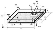
無線通信装置400は、図13Aに示すように、図1の固定部材120に相当する固定部材420、図1の同軸ケーブル150に相当する同軸ケーブル450、図1のアンテナ160に相当するアンテナ460、図1のアンテナ支持部材170に相当するアンテナ支持部材470、及び、図1の外装筐体180に相当する外装筐体480を有して構成されている。第4の実施形態に係る無線通信装置400においても、図1に示すセンサ110、バッテリー130及びプリント基板140に相当する構成部を更に有して構成されているものとする。また、外装筐体180には、面480Aに開口481、482及び483が設けられており、また、面480Bに開口484が設けられている。
図13Bは、図13Aにおけるxz断面図を示し、図13Cは、図13Aにおけるxy断面図を示し、図13Dは、図13Aにおけるyz断面図を示している。図13Aに示すように、開口483における開口面に対して垂直方向(y方向)から見た場合に、図13Bに示すように、少なくともアンテナ460の一部が開口483と重なっている。
ここで、第4の実施形態の一例として、無線通信装置400としてデジタルラジオグラフィー(DR)を適用した場合の効果を示すため、AET社製電磁界シミュレータのMW-STUDIOを用いて数値実験を実施した。
この場合、図13Aに示すアンテナ460は、ダイポールアンテナであり、第1のアンテナ素子461及び第2のアンテナ素子462を含み構成されている。このアンテナ460は、段差状のアンテナ支持部材470に接着固定されている。アンテナ支持部材470は、導電体からなる固定部材420に接着固定されている。導電体からなる外装筐体480は、導電体からなる固定部材420に固定されており、導電体からなる外装筐体480の面480Aには、一点鎖線で示す開口481、482及び483が設けられている。導電体からなる外装筐体480の面480Bには、一点鎖線で示す開口484が設けられ、各開口は樹脂部材で埋められている。なお、アンテナ460の近傍に設けられた開口483及び484は、アンテナ460が発する電磁波を外装筐体480の外部に放射するために設けられたものであり、開口483は、アンテナ460から最も近い位置に設けられた開口である。また、放射線を検出するセンサ110は、導電体からなる固定部材120に対してアンテナ460の裏面の側に配置されているために影響が低いことから、図示を省略している。
以下の表1に、図13B、図13C、図13D及び図16に図示された各寸法を示す。

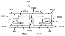
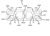
図14は、図13Aに示すアンテナ460の導体パターンの一例を示す図である。ここで、アンテナ460は、Molex社製の2.4/5GHzデュアルバンドのフレキシブルアンテナ(146153シリーズ)を用いた。このアンテナ460は、小型化のために第1のアンテナ素子461及び第2のアンテナ素子462を折り曲げて形成しているので、アンテナ素子461及び462のそれぞれの開放端部1401A及び1402Aは、アンテナ460の中央側を向いている。また、アンテナ460は、Wifiの通信周波数帯域に対応するため、2GHz帯域と5GHz帯域で電波が効率よく放射するような形状となっている。第1のアンテナ素子461の側端部1401Bと第2のアンテナ素子462の側端部1402Bとの間に、給電部である同軸ケーブル450が接続されている。
この図14に示すアンテナ460において、電界E及び磁界Hの強い領域を把握するため、アンテナ460の導体パターン寸法を測定し、AET社製の電磁界シミュレータのMW-STUDIOを用いて計算を実施した。
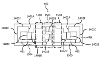
図15A及び図15Bは、図14に示すアンテナ460を用いて計算した磁界H及び電界Eの強度分布を示す図である。この図15A及び図15Bにおいて、図14に示す構成と同様の構成については同じ符号を付しており、その詳細な説明は省略する。
図15Aは、アンテナ460の磁界Hの強い領域を示し、図15Bは、電界Eの強い領域を示す。なお、観測周波数は2.4GHzと5.3GHzとした。図15Aに示す磁界の強い領域は、2.4GHz及び5.3GHzでほぼ同等となり、磁界が一番強い領域1501は、図15Aにおいて点線で示すように、同軸ケーブル450が接続された給電点、即ち側端部1401B及び1402Bを含む領域である。また、磁界が二番目に強い領域1502及び1503は、図15Aにおいて一点鎖線で示すように、給電点に隣接する領域であり、磁界が三番目に強い領域1504及び1505は、図15Aにおいて二点鎖線で示すように、アンテナ素子461及び462において開放端部1401A及び1402Aと給電点との間の領域である。なお、これらの領域で磁界Hの強度は一様ではなく、アンテナの開放端部1401A及び1402Aに近づくほど強度は弱くなる。
図15Bに示す電界Eの強い領域1511~1513及び1521~1523は、周波数2.4GHzにおいて、図15Bの点線で示すように、アンテナ素子461及び462の開放端部1401A及び1402Aと、アンテナ460の外形で長手方向の側端部1401C及び1402Cと、それらの間の側端部1401F及び1402Fの領域である。また、5.3GHzにおける電界の強い領域1514及び1524は、図15Bの一点鎖線で示すように、アンテナ素子461及び462の開放端部1401A及び1402Aの領域と、アンテナ素子461の側端部1401D、1401E及びアンテナ素子462の側端部1402D、1402Eの領域である。なお、これらの領域で電界E強度は一様ではなく、アンテナ素子461及び462の開放端部1401A及び1402Aに近づくほど強度は強くなる。
本実施形態においては、上述した磁界Hの強い領域を導電体からなる固定部材420に近づけ、上述した電界Eの強い領域を開口483に近づけて配置するため、アンテナ支持部材470を誘電体からなる段差形状の部材とした。
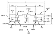
図16は、図14に示すアンテナ460の導体パターンの寸法の一例を示す図である。この図16において、図14乃至図15Bに示す構成と同様の構成については同じ符号を付しており、その詳細な説明は省略する。
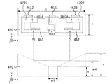
図16に示すw1×fの面積を有する領域では、固定部材420からアンテナ460までの最短距離は、2.8mmとした。w2×fの面積を有する領域では、固定部材420からアンテナ460までの最短距離は、寸法4.8mmとなるような形状とした。本実施形態の優位性を示すため、導電体からなる固定部材420からアンテナ素子461までの最短距離が、段差をつけずに2.8mm、3.8mm、4.8mmで一定となるアンテナ支持部材470を計算し、本実施形態の結果と比較した。
なお、SAR値は、面480A及び480Bに、DRの外形よりも大きい寸法の594×520×46[mm]の人体ファントムを密着させて配置した。SAR値の算出に関しては、国際規格測定で用いられる人体ファントムの溶剤の材料定数を使用し、導電率σは2[S/m]、比誘電率は52.21、Tanδは0.28、物質密度ρは1000とした。固定部材420等の導電体はステンレスとし、その導電率σは1100000[S/m]とした。SAR値は、人体ファントム内の電界Eを観測し、SAR[W/Kg]=E×E×ρ/σとして計算した。通信特性に関しては、人体ファントムを取り去った状態で計算し、放射効率を算出した。放射効率は、通信周波数における信号線に給電する電力と、アンテナ460を中心に1[m]の離れた地点を通過する放射電磁波の総電力との比を算出した。表2に、SAR値と放射効率を算出した結果を示す。
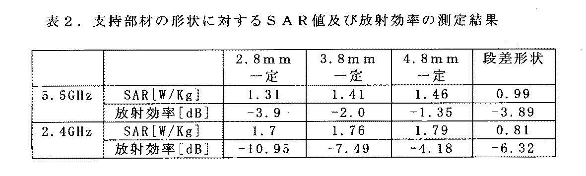
2.8mm一定と3.8mm一定と4.8mm一定の結果を比較すると、固定部材420からアンテナ460までの距離が近づく程、SAR値の値が低下し、2.8mm一定のSARの値が最も低くなっている。一方、放射効率の値は、開口に近づく程放射効率の値は高くなり、4.8mm一定の放射効率が最良となる。上記3水準の中では、3.8mm一定にすることで、電波放射量とSAR値のバランスを取ることができる。本実施形態の段差形状と3.8mm一定を比較すると、放射効率の値は段差形状が3.8mm一定よりも2.4GHzは改善したが、5.5GHzは若干劣化した。一方、SAR値については、2.4GHz及び5.5GHzにおいて低減していることがわかる。即ち、本実施形態の構造によって、通信周波数における電波放射量の減少を抑制しつつ、電磁波の人体吸収量に係るSAR値を低減することができる。
また、この段差形状において、導電体からなる固定部材420に近づける領域は、アンテナ素子461及び462の長さの何%程度になるかを算出した。
図17は、図14に示すアンテナ460の導体パターンの一例を示す図である。アンテナ素子461及び462の幅の中点を当該アンテナ素子に沿って描いたものが、点線1701及び1702である。第1のアンテナ素子461のアンテナ素子長は、側端部1401Bから開放端部1401Aまでの寸法32.6[mm]である。第2のアンテナ素子462のアンテナ素子長は、側端部1402Bから開放端部1402Aまでの寸法36.95[mm]である。また、地点P1及びP2は、表1の寸法W1の端部であり、側端部1401Bから地点P1までの距離は、14.015[mm]である。また、側端部1402Bから地点P2までの距離は、18.315[mm]である。即ち、第1のアンテナ素子461は、給電部から当該アンテナ素子の全長1701の43.0%が導電体に近づけて配置している。また、第2のアンテナ素子462は、給電部から当該アンテナ素子の全長1702の49.6%が導電体に近づけて配置している。
以上のことから、給電部からアンテナ素子461及び462の全長の概ね50%の地点、即ちアンテナ素子長の中間点までの領域を導電体からなる固定部材420に近づけることで、本実施形態の効果が得られる。
図18A及び図18Bは、図13Aに示すアンテナ460及びアンテナ支持部材470に相当する構成部の一例を示す図である。図13Aに示す段差状のアンテナ支持部材470に変えて、図18Aに示すように、Vの字形状のアンテナ支持部材470を適用した場合も同程度の効果が得られた。図18Bに示す寸法W3は4mmであり、固定部材420からの距離はs=2.8mm、r=4.8mmである。この形状において、固定部材420に近づける領域を、何%程度の距離で固定部材420に近づけて配置するかを算出した。地点P1及び地点P2において、固定部材420からの距離W4は、3.789mmである。即ち、固定部材420からアンテナ素子461及び462の最長距離rとアンテナ素子461及び462の最短距離sの差分の49.5%の寸法を最短距離sに近づけて配置している。言い換えると、地点P1及び地点P2の固定部材420からの距離W4が、固定部材420からアンテナ素子461及び462までの最長距離rと最短距離sとの差分の半分未満の寸法と最短距離sの寸法を足し合わせた寸法未満となるように、アンテナ素子461及び462を配置している。
以上のことから、導電体に近づける領域は、固定部材420からアンテナ素子461及び462までの最長距離と最短距離との差分の半分未満の寸法を最短距離に近づけて、アンテナ素子461及び462を配置することで本実施形態の効果が得られる。
第4の実施形態に係る無線通信装置400においても、第1の実施形態における無線通信装置100と同様の構成を採るようにしている。即ち、図18A及び図18Bに示すように、給電部である同軸ケーブル150及びアンテナ素子461及び462のそれぞれの第1領域4611及び4621を、アンテナ素子461及び462のそれぞれの第2領域4612及び4622よりも、導電体から構成されている固定部材120に近い位置に配置するようにしている。かかる構成によれば、第1の実施形態と同様に、通信周波数における電波放射量の減少を抑制しつつ、電磁波の人体吸収量に係るSAR値を低減することができる。
(その他の実施形態)
上述した本発明の実施形態では、アンテナとして、ダイポールアンテナや逆Fアンテナを適用したが、本発明においてはこれに限定されるものではなく、いわゆる逆Lアンテナやモノポールアンテナを適用することも可能である。モノポールアンテナを適用する場合、当該アンテナは、アンテナ素子に加えて、アンテナ素子のグラウンドとして用いられるグラウンド導体部(或いは、導電体からなる導電部)を更に含み構成されており、アンテナ素子は、その一端部が開放端部を構成し、その他端部とグラウンド導体部(或いは、上述した導電部)との間に給電部が設けられている形態を採る。また、逆Lアンテナを適用する場合、当該アンテナは、アンテナ素子に加えて、アンテナ素子のグラウンドとして用いられるグラウンド導体部(或いは、導電体からなる導電部)を更に含み構成されており、アンテナ素子は、その一端部が開放端部を構成し、一端部と他端部との間で折れ曲がった形状をしており、他端部とグラウンド導体部(或いは、上述した導電部)との間に給電部が設けられている形態を採る。
上述した本発明の実施形態では、アンテナとして、ダイポールアンテナや逆Fアンテナを適用したが、本発明においてはこれに限定されるものではなく、いわゆる逆Lアンテナやモノポールアンテナを適用することも可能である。モノポールアンテナを適用する場合、当該アンテナは、アンテナ素子に加えて、アンテナ素子のグラウンドとして用いられるグラウンド導体部(或いは、導電体からなる導電部)を更に含み構成されており、アンテナ素子は、その一端部が開放端部を構成し、その他端部とグラウンド導体部(或いは、上述した導電部)との間に給電部が設けられている形態を採る。また、逆Lアンテナを適用する場合、当該アンテナは、アンテナ素子に加えて、アンテナ素子のグラウンドとして用いられるグラウンド導体部(或いは、導電体からなる導電部)を更に含み構成されており、アンテナ素子は、その一端部が開放端部を構成し、一端部と他端部との間で折れ曲がった形状をしており、他端部とグラウンド導体部(或いは、上述した導電部)との間に給電部が設けられている形態を採る。
また、上述した実施形態では、無線通信装置として本発明をDRに適用した場合を示したが、無線通信機能を有するカメラ等に適用してもよい。
上記実施形態によれば、通信周波数における電波放射量の減少を抑制しつつ、電磁波の人体吸収量に係るSAR値を低減することができる。
本発明は上記実施の形態に制限されるものではなく、本発明の精神及び範囲から離脱することなく、様々な変更及び変形が可能である。従って、本発明の範囲を公にするために以下の請求項を添付する。
本願は、2019年10月29日提出の日本国特許出願特願2019-196344を基礎として優先権を主張するものであり、その記載内容の全てをここに援用する。
100:無線通信装置、110:センサ、120:固定部材、130:バッテリー、140:プリント基板、141:無線IC、142:信号配線、143:コネクタ、150:同軸ケーブル、160:アンテナ、161:第1のアンテナ素子、162:第2のアンテナ素子、170:アンテナ支持部材、180:外装筐体、181:開口
Claims (18)
- アンテナ素子を含み構成されているアンテナと、
導電体から構成され、前記アンテナを固定するための固定部材と、
前記アンテナに電気的に接続され、前記アンテナに電力を供給する給電部と、
導電体から構成され、前記アンテナ、前記固定部材および前記給電部を内包する外装筐体であって、前記アンテナからの電磁波を当該外装筐体の外部に放射させるための開口を備える外装筐体と、
を有し、
前記アンテナは、前記固定部材よりも前記外装筐体の前記開口に近い位置に配置されており、
前記給電部および前記アンテナ素子の前記給電部の側に位置する第1領域は、前記アンテナ素子の前記給電部とは反対側に位置する開放端部を含む第2領域よりも、前記固定部材に近い位置に配置されていることを特徴とする無線通信装置。 - 前記開口における開口面に対して垂直方向から見た場合に、少なくとも前記アンテナの一部が前記開口と重なっていることを特徴とする請求項1に記載の無線通信装置。
- 前記アンテナ素子の前記第2領域は、前記給電部および前記アンテナ素子の前記第1領域よりも、前記外装筐体の前記開口に近い位置に配置されていることを特徴とする請求項1または2に記載の無線通信装置。
- 前記アンテナ素子の前記第1領域は、前記アンテナ素子の長さにおける中間点未満の領域であることを特徴とする請求項1乃至3のいずれか1項に記載の無線通信装置。
- 前記アンテナ素子の前記第1領域の前記固定部材からの距離が、前記固定部材から前記アンテナ素子までの最長距離と最短距離との差分の半分未満の寸法と前記最短距離の寸法を足し合わせた寸法未満となるように、前記アンテナ素子を配置することを特徴とする請求項1乃至4のいずれか1項に記載の無線通信装置。
- 前記アンテナは、前記アンテナ素子と前記固定部材との間に、導電体から構成されている凸形状の突起物を更に含み構成されていることを特徴とする請求項1乃至5のいずれか1項に記載の無線通信装置。
- 前記アンテナは、
前記アンテナ素子として、第1のアンテナ素子および第2のアンテナ素子を含み構成されており、
前記第1のアンテナ素子および前記第2のアンテナ素子は、それぞれ、その一端部が前記開放端部を構成し、
前記第1のアンテナ素子の他端部と前記第2のアンテナ素子の他端部との間に前記給電部が設けられている、
ダイポールアンテナであることを特徴とする請求項1乃至6のいずれか1項に記載の無線通信装置。 - 前記アンテナを支持し、前記固定部材に固定される支持部材を更に有し、
前記支持部材は、前記第1のアンテナ素子および前記第2のアンテナ素子の前記一端部から前記他端部までを直線状に支持することを特徴とする請求項7に記載の無線通信装置。 - 前記アンテナを支持し、前記固定部材に固定される支持部材を更に有し、
前記支持部材は、前記第1のアンテナ素子および前記第2のアンテナ素子の前記一端部から前記他端部までの間で、当該アンテナ素子を折れ曲がり状および曲面状のうちの少なくとも一方で支持することを特徴とする請求項7に記載の無線通信装置。 - 前記アンテナは、
前記アンテナ素子のグラウンドとして用いられるグラウンド導体部を更に含み構成されており、
前記アンテナ素子は、その一端部が前記開放端部を構成し、その他端部が前記グラウンド導体部に短絡され、前記一端部と前記他端部との間の部分が前記給電部と電気的に接続される給電線となっている、
逆Fアンテナであることを特徴とする請求項1乃至6のいずれか1項に記載の無線通信装置。 - 前記アンテナを支持し、前記固定部材に固定される支持部材を更に有し、
前記支持部材は、前記アンテナ素子および前記グラウンド導体部を平面状で支持することを特徴とする請求項10に記載の無線通信装置。 - 前記アンテナを支持し、前記固定部材に固定される支持部材を更に有し、
前記支持部材は、前記アンテナ素子および前記グラウンド導体部を折れ曲がり状および曲面状のうちの少なくとも一方で支持することを特徴とする請求項10に記載の無線通信装置。 - 前記アンテナは、
導電体からなる導電部を更に含み構成されており、
前記アンテナ素子は、その一端部が前記開放端部を構成し、その他端部が前記導電部に短絡され、前記一端部と前記他端部との間の部分が前記給電部と電気的に接続される給電線となっている、
逆Fアンテナであることを特徴とする請求項1乃至6のいずれか1項に記載の無線通信装置。 - 前記アンテナは、
前記アンテナ素子のグラウンドとして用いられるグラウンド導体部を更に含み構成されており、
前記アンテナ素子は、その一端部が前記開放端部を構成し、その他端部と前記グラウンド導体部との間に前記給電部が設けられている、
モノポールアンテナであることを特徴とする請求項1乃至6のいずれか1項に記載の無線通信装置。 - 前記アンテナは、
導電体からなる導電部を更に含み構成されており、
前記アンテナ素子は、その一端部が前記開放端部を構成し、その他端部と前記導電部との間に前記給電部が設けられている、
モノポールアンテナであることを特徴とする請求項1乃至6のいずれか1項に記載の無線通信装置。 - 前記アンテナは、
前記アンテナ素子のグラウンドとして用いられるグラウンド導体部を更に含み構成されており、
前記アンテナ素子は、その一端部が前記開放端部を構成し、前記一端部と他端部との間で折れ曲がった形状をしており、前記他端部と前記グラウンド導体部との間に前記給電部が設けられている、
逆Lアンテナであることを特徴とする請求項1乃至6のいずれか1項に記載の無線通信装置。 - 前記アンテナは、
導電体からなる導電部を更に含み構成されており、
前記アンテナ素子は、その一端部が前記開放端部を構成し、前記一端部と他端部との間で折れ曲がった形状をしており、前記他端部と前記導電部との間に前記給電部が設けられている、
逆Lアンテナであることを特徴とする請求項1乃至6のいずれか1項に記載の無線通信装置。 - 前記無線通信装置は、放射線を検出するセンサを更に有するデジタルラジオグラフィーであることを特徴とする請求項1乃至17のいずれか1項に記載の無線通信装置。
Priority Applications (3)
| Application Number | Priority Date | Filing Date | Title |
|---|---|---|---|
| EP20881097.8A EP4047748B1 (en) | 2019-10-29 | 2020-10-26 | Wireless communication device |
| CN202080076405.7A CN114616718A (zh) | 2019-10-29 | 2020-10-26 | 无线通信装置 |
| US17/731,609 US12224488B2 (en) | 2019-10-29 | 2022-04-28 | Wireless communication apparatus |
Applications Claiming Priority (2)
| Application Number | Priority Date | Filing Date | Title |
|---|---|---|---|
| JP2019-196344 | 2019-10-29 | ||
| JP2019196344A JP7446770B2 (ja) | 2019-10-29 | 2019-10-29 | 無線通信装置 |
Related Child Applications (1)
| Application Number | Title | Priority Date | Filing Date |
|---|---|---|---|
| US17/731,609 Continuation US12224488B2 (en) | 2019-10-29 | 2022-04-28 | Wireless communication apparatus |
Publications (1)
| Publication Number | Publication Date |
|---|---|
| WO2021085391A1 true WO2021085391A1 (ja) | 2021-05-06 |
Family
ID=75714066
Family Applications (1)
| Application Number | Title | Priority Date | Filing Date |
|---|---|---|---|
| PCT/JP2020/040142 Ceased WO2021085391A1 (ja) | 2019-10-29 | 2020-10-26 | 無線通信装置 |
Country Status (5)
| Country | Link |
|---|---|
| US (1) | US12224488B2 (ja) |
| EP (1) | EP4047748B1 (ja) |
| JP (1) | JP7446770B2 (ja) |
| CN (1) | CN114616718A (ja) |
| WO (1) | WO2021085391A1 (ja) |
Families Citing this family (5)
| Publication number | Priority date | Publication date | Assignee | Title |
|---|---|---|---|---|
| US11990686B2 (en) * | 2020-05-22 | 2024-05-21 | Lg Electronics Inc. | Electronic device having antenna |
| US12267947B2 (en) | 2021-06-10 | 2025-04-01 | Canon Kabushiki Kaisha | Wiring board, electronic module, and electronic apparatus |
| JP2023086028A (ja) * | 2021-12-09 | 2023-06-21 | キヤノン株式会社 | 放射線検出装置 |
| US12334633B2 (en) * | 2022-04-20 | 2025-06-17 | Optisys, Inc. | Coaxial structure for enabling electromagnetic communications between a circuit board and antenna array |
| JP7819033B2 (ja) * | 2022-05-26 | 2026-02-24 | キヤノン株式会社 | アンテナ装置、アンテナ内蔵装置 |
Citations (8)
| Publication number | Priority date | Publication date | Assignee | Title |
|---|---|---|---|---|
| JP2000151262A (ja) * | 1998-08-05 | 2000-05-30 | Furukawa Electric Co Ltd:The | 小型アンテナ |
| JP2002280821A (ja) * | 2001-01-12 | 2002-09-27 | Furukawa Electric Co Ltd:The | アンテナ装置および端末機器 |
| JP2014003442A (ja) * | 2012-06-18 | 2014-01-09 | Tokai Rika Co Ltd | アンテナの収容構造 |
| WO2016125556A1 (ja) * | 2015-02-03 | 2016-08-11 | シャープ株式会社 | 無線機 |
| US9608331B1 (en) * | 2011-09-08 | 2017-03-28 | Ethertronics, Inc. | SAR reduction architecture and technique for wireless devices |
| JP2017111218A (ja) * | 2015-12-15 | 2017-06-22 | キヤノン株式会社 | 撮像装置 |
| JP2018517350A (ja) * | 2015-05-18 | 2018-06-28 | ノキア テクノロジーズ オーユー | 放射体として機能する導電性本体を有するワイヤレスポータブル電子デバイス |
| JP2019196344A (ja) | 2018-05-11 | 2019-11-14 | アース製薬株式会社 | 入浴剤組成物および香料の揮散持続方法 |
Family Cites Families (19)
| Publication number | Priority date | Publication date | Assignee | Title |
|---|---|---|---|---|
| JPH0936633A (ja) * | 1995-07-24 | 1997-02-07 | Sony Corp | アンテナ装置および携帯無線装置 |
| JP4510244B2 (ja) * | 2000-07-19 | 2010-07-21 | パナソニック株式会社 | アンテナ装置 |
| KR20020061103A (ko) | 2001-01-12 | 2002-07-22 | 후루까와덴끼고오교 가부시끼가이샤 | 안테나 장치 및 이 안테나 장치가 부착된 단말기기 |
| US6762723B2 (en) * | 2002-11-08 | 2004-07-13 | Motorola, Inc. | Wireless communication device having multiband antenna |
| JP4263972B2 (ja) * | 2003-09-11 | 2009-05-13 | 京セラ株式会社 | 表面実装型アンテナおよびアンテナ装置ならびに無線通信装置 |
| EP1814195A4 (en) * | 2004-10-01 | 2009-07-15 | Panasonic Corp | ANTENNA DEVICE AND WIRELESS TERMINAL WITH ANTENNA DEVICE |
| JP4633533B2 (ja) * | 2005-05-02 | 2011-02-16 | パナソニック株式会社 | 携帯無線機 |
| KR101788599B1 (ko) * | 2010-09-10 | 2017-10-20 | 엘지전자 주식회사 | 동글장치 |
| US9444147B2 (en) * | 2011-07-18 | 2016-09-13 | The United States Of America As Represented By The Secretary Of The Army | Ultra-wide-band (UWB) antenna assembly with at least one director and electromagnetic reflective subassembly and method |
| US10020571B2 (en) * | 2013-04-09 | 2018-07-10 | Essex Electronics, Inc. | Antenna mounting system for metallic structures |
| US9748657B1 (en) * | 2013-11-21 | 2017-08-29 | FIRST RF Corp. | Cavity backed dipole antenna |
| US9356661B2 (en) * | 2014-04-23 | 2016-05-31 | Apple Inc. | Electronic device with near-field antenna operating through display |
| JP6112263B2 (ja) * | 2014-09-26 | 2017-04-12 | 株式会社村田製作所 | 電子機器 |
| US10978802B2 (en) * | 2015-02-18 | 2021-04-13 | Canon Kabushiki Kaisha | Wireless communication device and electronic apparatus |
| JP6489860B2 (ja) | 2015-02-18 | 2019-03-27 | キヤノン株式会社 | 無線通信装置及び電子機器 |
| JP6626352B2 (ja) | 2016-01-21 | 2019-12-25 | キヤノン株式会社 | アンテナ、無線通信装置、および電子機器 |
| CN111066202B (zh) * | 2017-09-08 | 2021-05-28 | 株式会社村田制作所 | 支持双频段的天线装置 |
| US11095017B2 (en) * | 2018-07-13 | 2021-08-17 | Apple Inc. | Electronic device having angle of arrival detection capabilities |
| US10886648B2 (en) | 2018-11-26 | 2021-01-05 | Canon Kabushiki Kaisha | Communication module, electronic device, and image pickup apparatus |
-
2019
- 2019-10-29 JP JP2019196344A patent/JP7446770B2/ja active Active
-
2020
- 2020-10-26 WO PCT/JP2020/040142 patent/WO2021085391A1/ja not_active Ceased
- 2020-10-26 CN CN202080076405.7A patent/CN114616718A/zh active Pending
- 2020-10-26 EP EP20881097.8A patent/EP4047748B1/en active Active
-
2022
- 2022-04-28 US US17/731,609 patent/US12224488B2/en active Active
Patent Citations (8)
| Publication number | Priority date | Publication date | Assignee | Title |
|---|---|---|---|---|
| JP2000151262A (ja) * | 1998-08-05 | 2000-05-30 | Furukawa Electric Co Ltd:The | 小型アンテナ |
| JP2002280821A (ja) * | 2001-01-12 | 2002-09-27 | Furukawa Electric Co Ltd:The | アンテナ装置および端末機器 |
| US9608331B1 (en) * | 2011-09-08 | 2017-03-28 | Ethertronics, Inc. | SAR reduction architecture and technique for wireless devices |
| JP2014003442A (ja) * | 2012-06-18 | 2014-01-09 | Tokai Rika Co Ltd | アンテナの収容構造 |
| WO2016125556A1 (ja) * | 2015-02-03 | 2016-08-11 | シャープ株式会社 | 無線機 |
| JP2018517350A (ja) * | 2015-05-18 | 2018-06-28 | ノキア テクノロジーズ オーユー | 放射体として機能する導電性本体を有するワイヤレスポータブル電子デバイス |
| JP2017111218A (ja) * | 2015-12-15 | 2017-06-22 | キヤノン株式会社 | 撮像装置 |
| JP2019196344A (ja) | 2018-05-11 | 2019-11-14 | アース製薬株式会社 | 入浴剤組成物および香料の揮散持続方法 |
Non-Patent Citations (2)
| Title |
|---|
| "Controlling radiated emissions by design", 30 June 2000, MARUZEN PUBLISHING CO., LTD., article "compiled under the supervision of Mitsutoshi Hatori", pages: 238 |
| See also references of EP4047748A4 |
Also Published As
| Publication number | Publication date |
|---|---|
| US20220263236A1 (en) | 2022-08-18 |
| CN114616718A (zh) | 2022-06-10 |
| EP4047748A4 (en) | 2023-11-08 |
| EP4047748B1 (en) | 2024-12-11 |
| EP4047748A1 (en) | 2022-08-24 |
| JP7446770B2 (ja) | 2024-03-11 |
| US12224488B2 (en) | 2025-02-11 |
| JP2021072472A (ja) | 2021-05-06 |
Similar Documents
| Publication | Publication Date | Title |
|---|---|---|
| JP7446770B2 (ja) | 無線通信装置 | |
| JP6489860B2 (ja) | 無線通信装置及び電子機器 | |
| US10651540B2 (en) | Antenna unit and electronic device | |
| EP3419114A1 (en) | Antenna device and electronic apparatus | |
| CN106992357A (zh) | 天线、无线通信设备和电子设备 | |
| EP4194904B1 (en) | Radiation detection apparatus | |
| JP6887483B2 (ja) | 電子機器 | |
| CN110661077B (zh) | 无线通信装置 | |
| Ashyap et al. | A Compact AMC-Backed Meander Line Antenna With Low SAR and High Gain for Wearable ISM Band Applications | |
| CN107925159A (zh) | 天线构造和电子设备 | |
| JP7734605B2 (ja) | 無線端末 | |
| JP6512856B2 (ja) | 無線通信装置及び電子機器 | |
| JP6512857B2 (ja) | 無線通信装置及び電子機器 | |
| Quddious et al. | A Miniaturized Unidirectional On-Body Antenna for Ultra-Wideband Electromagnetic Medical Applications | |
| JP2017220636A (ja) | ノイズ遮蔽板及びノイズ遮蔽装置 | |
| CN120569855A (zh) | 电子设备 | |
| JP2023173762A (ja) | アンテナ装置、アンテナ内蔵装置 | |
| CN121307479A (zh) | 电子设备 | |
| TWI483470B (zh) | 降低電磁波特定吸收比率的天線組合 | |
| WO2025185595A1 (zh) | 一种电子设备 | |
| CN116256791A (zh) | 放射线检测装置 | |
| CN119852689A (zh) | 天线装置及电子设备 | |
| CN117673709A (zh) | 开回路天线及电子装置 | |
| El Halaoui et al. | Research Article Multiband Planar Inverted-F Antenna with Independent Operating Bands Control for Mobile Handset Applications | |
| JPH06283911A (ja) | ピン・ストリップ線路垂直変換器 |
Legal Events
| Date | Code | Title | Description |
|---|---|---|---|
| 121 | Ep: the epo has been informed by wipo that ep was designated in this application |
Ref document number: 20881097 Country of ref document: EP Kind code of ref document: A1 |
|
| NENP | Non-entry into the national phase |
Ref country code: DE |
|
| ENP | Entry into the national phase |
Ref document number: 2020881097 Country of ref document: EP Effective date: 20220518 |