WO2021085401A1 - プラスチックシンチレーションファイバ及びその製造方法 - Google Patents
プラスチックシンチレーションファイバ及びその製造方法 Download PDFInfo
- Publication number
- WO2021085401A1 WO2021085401A1 PCT/JP2020/040174 JP2020040174W WO2021085401A1 WO 2021085401 A1 WO2021085401 A1 WO 2021085401A1 JP 2020040174 W JP2020040174 W JP 2020040174W WO 2021085401 A1 WO2021085401 A1 WO 2021085401A1
- Authority
- WO
- WIPO (PCT)
- Prior art keywords
- core
- clad layer
- fiber
- layer
- phosphor
- Prior art date
- Legal status (The legal status is an assumption and is not a legal conclusion. Google has not performed a legal analysis and makes no representation as to the accuracy of the status listed.)
- Ceased
Links
Images


Classifications
-
- C—CHEMISTRY; METALLURGY
- C09—DYES; PAINTS; POLISHES; NATURAL RESINS; ADHESIVES; COMPOSITIONS NOT OTHERWISE PROVIDED FOR; APPLICATIONS OF MATERIALS NOT OTHERWISE PROVIDED FOR
- C09K—MATERIALS FOR MISCELLANEOUS APPLICATIONS, NOT PROVIDED FOR ELSEWHERE
- C09K11/00—Luminescent materials, e.g. electroluminescent or chemiluminescent
- C09K11/08—Luminescent materials, e.g. electroluminescent or chemiluminescent containing inorganic luminescent materials
- C09K11/58—Luminescent materials, e.g. electroluminescent or chemiluminescent containing inorganic luminescent materials containing copper, silver or gold
- C09K11/582—Chalcogenides
- C09K11/584—Chalcogenides with zinc or cadmium
-
- G—PHYSICS
- G02—OPTICS
- G02B—OPTICAL ELEMENTS, SYSTEMS OR APPARATUS
- G02B6/00—Light guides; Structural details of arrangements comprising light guides and other optical elements, e.g. couplings
- G02B6/02—Optical fibres with cladding with or without a coating
-
- B—PERFORMING OPERATIONS; TRANSPORTING
- B29—WORKING OF PLASTICS; WORKING OF SUBSTANCES IN A PLASTIC STATE IN GENERAL
- B29D—PRODUCING PARTICULAR ARTICLES FROM PLASTICS OR FROM SUBSTANCES IN A PLASTIC STATE
- B29D11/00—Producing optical elements, e.g. lenses or prisms
- B29D11/00663—Production of light guides
- B29D11/00682—Production of light guides with a refractive index gradient
-
- B—PERFORMING OPERATIONS; TRANSPORTING
- B29—WORKING OF PLASTICS; WORKING OF SUBSTANCES IN A PLASTIC STATE IN GENERAL
- B29D—PRODUCING PARTICULAR ARTICLES FROM PLASTICS OR FROM SUBSTANCES IN A PLASTIC STATE
- B29D11/00—Producing optical elements, e.g. lenses or prisms
- B29D11/00663—Production of light guides
- B29D11/00701—Production of light guides having an intermediate layer between core and cladding
-
- C—CHEMISTRY; METALLURGY
- C09—DYES; PAINTS; POLISHES; NATURAL RESINS; ADHESIVES; COMPOSITIONS NOT OTHERWISE PROVIDED FOR; APPLICATIONS OF MATERIALS NOT OTHERWISE PROVIDED FOR
- C09K—MATERIALS FOR MISCELLANEOUS APPLICATIONS, NOT PROVIDED FOR ELSEWHERE
- C09K11/00—Luminescent materials, e.g. electroluminescent or chemiluminescent
- C09K11/02—Use of particular materials as binders, particle coatings or suspension media therefor
-
- C—CHEMISTRY; METALLURGY
- C09—DYES; PAINTS; POLISHES; NATURAL RESINS; ADHESIVES; COMPOSITIONS NOT OTHERWISE PROVIDED FOR; APPLICATIONS OF MATERIALS NOT OTHERWISE PROVIDED FOR
- C09K—MATERIALS FOR MISCELLANEOUS APPLICATIONS, NOT PROVIDED FOR ELSEWHERE
- C09K11/00—Luminescent materials, e.g. electroluminescent or chemiluminescent
- C09K11/06—Luminescent materials, e.g. electroluminescent or chemiluminescent containing organic luminescent materials
-
- C—CHEMISTRY; METALLURGY
- C09—DYES; PAINTS; POLISHES; NATURAL RESINS; ADHESIVES; COMPOSITIONS NOT OTHERWISE PROVIDED FOR; APPLICATIONS OF MATERIALS NOT OTHERWISE PROVIDED FOR
- C09K—MATERIALS FOR MISCELLANEOUS APPLICATIONS, NOT PROVIDED FOR ELSEWHERE
- C09K11/00—Luminescent materials, e.g. electroluminescent or chemiluminescent
- C09K11/08—Luminescent materials, e.g. electroluminescent or chemiluminescent containing inorganic luminescent materials
- C09K11/77—Luminescent materials, e.g. electroluminescent or chemiluminescent containing inorganic luminescent materials containing rare earth metals
- C09K11/7728—Luminescent materials, e.g. electroluminescent or chemiluminescent containing inorganic luminescent materials containing rare earth metals containing europium
- C09K11/7732—Halogenides
- C09K11/7733—Halogenides with alkali or alkaline earth metals
-
- C—CHEMISTRY; METALLURGY
- C09—DYES; PAINTS; POLISHES; NATURAL RESINS; ADHESIVES; COMPOSITIONS NOT OTHERWISE PROVIDED FOR; APPLICATIONS OF MATERIALS NOT OTHERWISE PROVIDED FOR
- C09K—MATERIALS FOR MISCELLANEOUS APPLICATIONS, NOT PROVIDED FOR ELSEWHERE
- C09K11/00—Luminescent materials, e.g. electroluminescent or chemiluminescent
- C09K11/08—Luminescent materials, e.g. electroluminescent or chemiluminescent containing inorganic luminescent materials
- C09K11/77—Luminescent materials, e.g. electroluminescent or chemiluminescent containing inorganic luminescent materials containing rare earth metals
- C09K11/7728—Luminescent materials, e.g. electroluminescent or chemiluminescent containing inorganic luminescent materials containing rare earth metals containing europium
- C09K11/7734—Aluminates
-
- G—PHYSICS
- G01—MEASURING; TESTING
- G01T—MEASUREMENT OF NUCLEAR OR X-RADIATION
- G01T1/00—Measuring X-radiation, gamma radiation, corpuscular radiation, or cosmic radiation
- G01T1/16—Measuring radiation intensity
- G01T1/20—Measuring radiation intensity with scintillation detectors
- G01T1/201—Measuring radiation intensity with scintillation detectors using scintillating fibres
-
- G—PHYSICS
- G01—MEASURING; TESTING
- G01T—MEASUREMENT OF NUCLEAR OR X-RADIATION
- G01T1/00—Measuring X-radiation, gamma radiation, corpuscular radiation, or cosmic radiation
- G01T1/16—Measuring radiation intensity
- G01T1/20—Measuring radiation intensity with scintillation detectors
- G01T1/2012—Measuring radiation intensity with scintillation detectors using stimulable phosphors, e.g. stimulable phosphor sheets
-
- G—PHYSICS
- G01—MEASURING; TESTING
- G01T—MEASUREMENT OF NUCLEAR OR X-RADIATION
- G01T1/00—Measuring X-radiation, gamma radiation, corpuscular radiation, or cosmic radiation
- G01T1/16—Measuring radiation intensity
- G01T1/20—Measuring radiation intensity with scintillation detectors
- G01T1/203—Measuring radiation intensity with scintillation detectors the detector being made of plastics
-
- G—PHYSICS
- G01—MEASURING; TESTING
- G01T—MEASUREMENT OF NUCLEAR OR X-RADIATION
- G01T3/00—Measuring neutron radiation
- G01T3/06—Measuring neutron radiation with scintillation detectors
-
- G—PHYSICS
- G02—OPTICS
- G02B—OPTICAL ELEMENTS, SYSTEMS OR APPARATUS
- G02B6/00—Light guides; Structural details of arrangements comprising light guides and other optical elements, e.g. couplings
- G02B6/02—Optical fibres with cladding with or without a coating
- G02B6/036—Optical fibres with cladding with or without a coating core or cladding comprising multiple layers
- G02B6/03616—Optical fibres characterised both by the number of different refractive index layers around the central core segment, i.e. around the innermost high index core layer, and their relative refractive index difference
- G02B6/03622—Optical fibres characterised both by the number of different refractive index layers around the central core segment, i.e. around the innermost high index core layer, and their relative refractive index difference having 2 layers only
-
- G—PHYSICS
- G02—OPTICS
- G02B—OPTICAL ELEMENTS, SYSTEMS OR APPARATUS
- G02B6/00—Light guides; Structural details of arrangements comprising light guides and other optical elements, e.g. couplings
- G02B6/02—Optical fibres with cladding with or without a coating
- G02B6/02033—Core or cladding made from organic material, e.g. polymeric material
-
- G—PHYSICS
- G02—OPTICS
- G02B—OPTICAL ELEMENTS, SYSTEMS OR APPARATUS
- G02B6/00—Light guides; Structural details of arrangements comprising light guides and other optical elements, e.g. couplings
- G02B6/02—Optical fibres with cladding with or without a coating
- G02B6/036—Optical fibres with cladding with or without a coating core or cladding comprising multiple layers
- G02B6/03694—Multiple layers differing in properties other than the refractive index, e.g. attenuation, diffusion, stress properties
Definitions
- the present invention relates to a plastic scintillation fiber and a method for manufacturing the same.
- the conventional plastic scintillation fiber is a plastic fiber in which the outer peripheral surface of the core, which is a scintillator, is covered with a clad layer having a lower refractive index than the core, and is mainly used for radiation detection.
- the core is composed of a polymer material obtained by adding an organic phosphor to a base material having an aromatic ring such as polystyrene or polyvinyltoluene.
- the clad layer is composed of a low refractive index polymer material such as polymethylmethacrylate or fluorine-containing polymethylmethacrylate.
- the core base material of the scintillation fiber has an aromatic ring, and when the irradiated radiation crosses the scintillation fiber, it absorbs a part of the energy by re-radiation of secondary particles in the core and emits it as ultraviolet rays. It has the characteristic of doing. If no phosphor is added to the core base material, this ultraviolet light is self-absorbed by the core base material itself and disappears without being transmitted in the core.
- this ultraviolet ray is absorbed by the phosphor added to the core base material, and the light having a longer wavelength is re-emitted. Therefore, by selecting an appropriate phosphor, it is converted into light having a long wavelength such as blue, which is difficult to be self-absorbed by the core substrate, and transmitted in the fiber.
- the light transmitted in the fiber is detected by a detector connected to one end or both ends.
- the scintillation fiber has two functions of light emission by radiation detection and optical transmission, and is used for applications such as calculating the passing position of radiation.
- it is important how to efficiently convert the ultraviolet light emitted from the core into a long wavelength and transmit it over a long distance.
- plastic wavelength conversion fiber (WLSF: Wavelength Shifting Fiber) is often used alongside scintillation fiber.
- the wavelength conversion fiber is used in combination with, for example, a plastic scintillator that emits blue light. Grooves and holes are provided in a plate-shaped or rod-shaped plastic scintillator, and a wavelength conversion fiber that absorbs blue light and converts it into green light is embedded.
- a wavelength conversion fiber that is thin, easy to bend, and capable of long-distance transmission is preferably used.
- a large number of wavelength conversion fibers can be freely laid out up to an external photoelectric detector.
- the core of the wavelength conversion fiber is made of polystyrene or polymethylmethacrylate resin, and a phosphor for wavelength conversion is dissolved in it.
- the scintillation light incident from the external scintillator is absorbed by the phosphor in the core, the wavelength is efficiently converted, and the scintillation light is transmitted in the fiber.
- the scintillator to be combined with the wavelength conversion fiber is not limited to a plastic scintillator, but an inorganic scintillator having high sensitivity to neutrons and the like is used.
- the wavelength conversion fiber can easily collect the scintillation light emitted from a large-area or long scintillator or a special scintillator for neutron detection or the like.
- the wavelength conversion fiber transmits the wavelength-converted light in the core and can be freely connected to the photoelectric detector.
- the inorganic scintillator has an attenuation length of several mm and is not highly transparent, and cannot transmit emitted light (that is, scintillation light) over a long distance. Further, since there are restrictions on the crystal size, it is difficult to perform optical transmission to the photoelectric detector by an inorganic scintillator.
- Patent Documents 2 and 3 a sheet in which fine particles obtained by crushing an inorganic scintillator are dispersed in a transparent resin has been developed for detecting neutrons and heavy particle beams.
- the difference in refractive index between the inorganic scintillator and the transparent resin is large, transparency cannot be ensured, and the sheet itself cannot efficiently transmit light to the photoelectric detector.
- the wavelength conversion fiber is placed along the end face and surface of the scintillator, and the wavelength conversion fiber is used for optical transmission to the photoelectric detector.
- the detected light can be transmitted over a longer distance.
- a large number of post-processings in which a scintillator and a wavelength conversion fiber are combined are required. Become.
- the core itself is required to have high transparency because the core itself emits scintillation light and optical transmission is performed to the photoelectric detector. Therefore, it is not possible to obtain a plastic scintillation fiber for detecting a neutron beam or a heavy particle beam by including a material that emits scintillation light by irradiation with a neutron beam or a heavy particle beam in the core.
- the scintillation light irradiated from the external scintillator is wavelength-converted in the core and transmitted through the core, so that the core is required to have high transparency. Therefore, it is not possible to obtain a plastic scintillation fiber for detecting a neutron beam or a heavy particle beam by including a material that emits scintillation light by irradiation with a neutron beam or a heavy particle beam in the core.
- a conventional scintillation detector using a wavelength conversion fiber requires post-processing that combines a scintillator and a wavelength conversion fiber. Further, in the case of image detection, it is necessary to separate and combine one scintillator for each of a large number of wavelength conversion fibers, which makes processing extremely difficult.
- the present invention has been made in view of such circumstances, and an object of the present invention is to provide a plastic scintillation fiber capable of detecting at least one of a neutron beam and a heavy particle beam and having excellent productivity.
- the plastic scintillation fiber according to one aspect of the present invention is The outermost layer containing a material that emits scintillation light by irradiation of at least one of neutron beam and heavy particle beam, A core provided inside the outermost layer and containing at least one type of phosphor that absorbs the scintillation light and converts the wavelength into a long wavelength. A clad layer that covers the outer peripheral surface of the core and has a lower refractive index than that of the core is provided.
- the wavelength conversion fiber including the core and the clad layer and the outermost peripheral layer covering the outer peripheral surface of the wavelength conversion fiber are integrally formed.
- scintillation light is generated in the outermost peripheral layer by irradiation with neutron rays or heavy particle beams, and the scintillation light is absorbed by the internal core to convert the wavelength and optical transmission. To do. Therefore, neutron rays and heavy particle beams, which are difficult to detect with conventional plastic scintillation fibers, can be detected. Further, since the wavelength conversion fiber including the core and the clad layer and the outermost peripheral layer covering the outer peripheral surface of the wavelength conversion fiber are integrally formed, post-processing for combining the scintillator and the wavelength conversion fiber, which has been conventionally required, is unnecessary. It becomes. That is, it is possible to provide a highly productive plastic scintillation fiber capable of detecting at least one of a neutron beam and a heavy particle beam.
- the material may be fine particles of an inorganic fluorescent substance, and the outermost peripheral layer may be made of a transparent resin in which the fine particles are dispersed. It can detect neutron rays and heavy particle beams with high sensitivity.
- wavelength conversion fiber and the outermost peripheral layer may be integrally formed by wire drawing. Productivity is improved.
- the clad layer may have a multi-clad structure including an inner clad layer and an outer clad layer that covers the outer peripheral surface of the inner clad layer and has a refractive index lower than that of the inner clad layer. .. The total reflection angle becomes wider and the light emission becomes higher.
- the method for manufacturing a plastic scintillation fiber according to one aspect of the present invention is as follows.
- the outermost layer containing a phosphor that emits scintillation light by irradiation of at least one of neutron beam and heavy particle beam,
- a core provided inside the outermost layer and containing at least one type of phosphor that absorbs the scintillation light and converts the wavelength into a long wavelength.
- a method for producing a plastic scintillation fiber which covers the outer peripheral surface of the core and includes a clad layer having a refractive index lower than that of the core.
- the method for manufacturing a plastic scintillation fiber according to one aspect of the present invention is as follows.
- the outermost layer containing a phosphor that emits scintillation light by irradiation of at least one of neutron beam and heavy particle beam,
- a core having a high refractive index which is provided inside the outermost layer and contains at least one kind of phosphor that absorbs the scintillation light and converts the wavelength into a long wavelength.
- a method for producing a plastic scintillation fiber which covers the outer peripheral surface of the core and includes a clad layer having a refractive index lower than that of the core.
- the outermost peripheral layer is coated on the surface of the clad layer.
- a plastic scintillation fiber capable of detecting at least one of a neutron beam and a heavy particle beam and having excellent productivity.
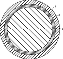
- FIG. It is sectional drawing of the plastic scintillation fiber which concerns on Embodiment 1.
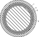
- FIG. It is sectional drawing of the plastic scintillation fiber which concerns on the modification of Embodiment 1.
- FIG. It is a perspective view which shows the manufacturing method of the plastic scintillation fiber which concerns on Embodiment 1.
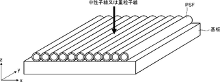
- FIG. It is a perspective view which shows the application example of the scintillation fiber which concerns on Embodiment 1.
- FIG. It is a graph which shows the emission spectrum of the neutron phosphor LiCaAlF 6 : Eu, and the absorption and emission spectrum of the wavelength conversion phosphor BBOT.
- FIG. 1 is a cross-sectional view of the plastic scintillation fiber according to the first embodiment.
- the plastic scintillation fiber according to the first embodiment includes an outermost peripheral layer 1, a core 2, and a clad layer 3.
- the outermost layer 1 is made of a resin containing a material that scintillates and emits light by at least one of a neutron beam and a heavy particle beam (for example, an alpha ray).
- the outermost layer 1 is made of a transparent resin (transparent organic polymer) in which fine particles of an inorganic phosphor (inorganic scintillator) that emits scintillation by neutron rays or heavy particle beams are dispersed.
- the outermost peripheral layer 1 may emit sufficient light and be transparent to the extent that scintillation light penetrates the clad layer 3 and enters the core 2 in the center, and high transparency is not required, but it is as transparent as possible. The thinner one is desirable. Even if the outermost layer 1 which is a scintillator layer has low transparency, long-distance transmission is possible if the core 2 at the center, which is responsible for optical transmission, has high transparency.
- the core 2 is provided inside the outermost layer 1, and is made of a transparent resin having a high refractive index containing at least one kind of phosphor that absorbs the scintillation light generated in the outermost layer 1 and converts it into a longer wavelength.
- the refractive index of the transparent resin constituting the core 2 is preferably 1.5 or more.
- the clad layer 3 covers the outer peripheral surface of the core 2 and is made of a transparent resin having a lower refractive index than that of the core 2.
- the wavelength conversion fiber composed of the core 2 and the clad layer 3 and the outermost peripheral layer 1 covering the outer peripheral surface of the wavelength conversion fiber are integrally formed.
- the transparency of the clad layer 3 is as important as the transparency of the core 2.
- the transparency of the outermost layer 1 is not so important.
- the thickness of the clad layer 3 is preferably 3 ⁇ m to 100 ⁇ m, which is sufficiently thicker than the depth of the evanescent wave in which the transmitted light seeps from the core 2 to the clad layer 3.
- the refractive indexes of the clad layer 3 and the outermost peripheral layer 1 may be the same, or the same transparent resin may be used.
- the core 2 may include a second phosphor for further wavelength conversion in order to match the wavelength sensitivity of a photoelectric detector such as a photomultiplier tube (PMT) or an avalanche photodiode (APD).
- a photoelectric detector such as a photomultiplier tube (PMT) or an avalanche photodiode (APD). The details of the phosphor will be described later.
- the plastic scintillation fiber according to the first embodiment scintillation light is generated in the outermost peripheral layer 1 due to irradiation with neutron rays or heavy particle beams, and the scintillation light is absorbed by the internal core 2 to convert the wavelength and light. To transmit. Therefore, neutron rays and heavy particle beams, which are difficult to detect with conventional plastic scintillation fibers, can be detected with high sensitivity. That is, the plastic scintillation fiber according to the first embodiment is a composite type plastic optical fiber having both a neutron beam and heavy particle beam scintillation function and a wavelength conversion function.
- the wavelength conversion fiber composed of the core 2 and the clad layer 3 and the outermost peripheral layer 1 covering the outer peripheral surface of the wavelength conversion fiber are integrally formed. Therefore, post-processing that combines a scintillator and a wavelength conversion fiber, which has been required in the past, is not required, and productivity can be dramatically improved and costs can be reduced as compared with the conventional case.
- FIG. 2 is a cross-sectional view of a plastic scintillation fiber according to a modified example of the first embodiment.
- the plastic scintillation fiber according to the modified example includes a clad layer 3 as an inner clad layer and a clad layer 4 as an outer clad layer. That is, the clad layer has a multi-clad structure including an inner clad layer (clad layer 3) and an outer clad layer (clad layer 4).
- the clad layer 4 covers the outer peripheral surface of the clad layer 3 and is made of a transparent resin having a lower refractive index than that of the clad layer 3.
- the re-emitted light whose wavelength is converted in the core 2 is radiated isotropically in a solid angle in the core 2. Therefore, only light within the total reflection angle based on the difference in refractive index between the core 2 and the clad layer 3 or the clad layer 4 can be transmitted in the fiber direction. Since the plastic scintillation fiber according to the modified example includes the clad layer 4 having a low refractive index in addition to the clad layer 3, the total reflection angle is wider (the numerical aperture NA is larger) than the plastic scintillation fiber of FIG. High light emission.
- the outermost layer 1 which is a scintillator layer is made of a resin containing a material (fluorescent substance) that emits scintillation light by irradiation with at least one of a neutron beam and a heavy particle beam (alpha ray, etc.).
- the outermost layer 1 is made of a transparent resin in which fine particles of an inorganic phosphor that emits scintillation by neutron rays or heavy particle beams are uniformly or non-uniformly dispersed.
- the transparent resin constituting the outermost outer layer 1 is preferably thermoplastic so that it can be thinly drawn by heating.
- a transparent resin any one of a methacrylic acid ester monomer group represented by methyl methacrylate, an acrylic acid ester monomer group represented by methyl acrylate, and an aromatic monomer group having a vinyl group represented by styrene.
- a homopolymer or a copolymer composed of the above is preferable.
- the refractive index of the transparent resin constituting the outermost outermost layer 1 is not limited from the viewpoint of optical transmission performance, but it is preferably close to the refractive index of the inorganic phosphor to be dispersed. This is because if the difference in refractive index between the inorganic phosphor to be dispersed and the transparent resin as the dispersion medium is large, light scattering becomes large and the scintillation light generated in the outermost peripheral layer 1 does not effectively reach the core 2.
- an inorganic phosphor as described in Patent Documents 1 and 2 may be preferable because it has no sensitivity to gamma rays and selectively emits light only by neutron rays.
- the outermost layer 1 is formed by dispersing 1 to 30% by mass of fine particles of LiCaAlF 6 : Eu, an inorganic phosphor that contains lithium 6 and is doped with Eu and scintillates and emits light by neutron rays.
- the transparent resin for dispersing the fine particles of the inorganic phosphor can be preferably selected from the same as the core 2 or the clad layers 3 and 4.
- the outermost layer 1 scintillates ultraviolet light of 350 to 400 nm by neutron rays.
- the outermost layer 1 is a transparent resin in which fine particles of the inorganic phosphor ZnS: Ag that scintillates and emits light by heavy particle beams (alpha rays, etc.) are dispersed.
- the transparent resin for dispersing the fine particles of the inorganic phosphor can also be preferably selected from the same as the core 2 or the clad layers 3 and 4.
- the outermost layer 1 emits visible light of 400 to 500 nm by heavy particle beams.
- the particle size of the inorganic phosphor dispersed in the transparent resin is preferably 0.1 to 100 ⁇ m, more preferably 1 to 10 ⁇ m.
- the concentration of the inorganic phosphor to be dispersed is preferably 1 to 50% by mass, more preferably 5 to 30% by mass. If the concentration is too low, the luminous efficiency of the neutron beam or heavy particle beam in the outermost layer 1 deteriorates. If the concentration is too high, it becomes difficult to disperse in the transparent resin, or it becomes difficult to draw a line by heating.
- the inorganic phosphor to be dispersed is appropriately selected depending on the neutron beam or heavy particle beam to be detected, and is not limited to the above. Further, the particle size and concentration of the inorganic phosphor are also appropriately selected depending on the detection performance, the difficulty of production, and the like, and are not limited to the above. Further, the transparent resin to be dispersed is also appropriately selected depending on the dispersibility, ease of production, and the like, and is not limited to the above.
- a polymer composed of an aromatic monomer having a vinyl group has a high refractive index and is preferable.
- the difference in refractive index between the core 2 and the clad layer 3 becomes large, and the total reflection angle becomes wide. That is, among the wavelength-converted light in the core 2, the light having a wider angle can be transmitted, so that a scintillation fiber having higher light emission can be obtained.
- the wavelength conversion phosphor contained in the core 2 is an organic phosphor having an aromatic ring and a structure capable of resonating, and it is preferable that a single molecule is dissolved in the core 2.
- Typical phosphors include 2- (4-t-butylphenyl) -5- (4-biphenyl) -1,3,4-oxadiazole (b-PBD), 2-which absorbs 250 to 350 nm.
- BDB 4,4'-bis- (2,5-dimethylstyryl) -diphenyl
- BBOT 2,5-bis- (5-t-butyl-benzoxazoyl) thiophene
- POPOP 4-Bis- (2- (5-phenyloxazolyl)) Benzene
- DMPOPOP 1,4-Bis- (4-Methyl-5-Phenyl-2-oxazolyl) Benzene
- DMPOPOP 1,4- Diphenyl-1,3-butadiene
- DPH 1,6-diphenyl-1,3,5-hexatriene
- HOSTASOLE YELLOW 3G that absorbs 400 to 500 nm
- MACROLEX FLUORESCENT YELLOW 10GN Kayaset Yellow SF-G
- LUMOGEN F ORANGE 240 that absorbs 500 to 600 nm
- LUMOGEN F RED 300 and the like.
- the absorption spectrum of the wavelength-converted phosphor contained in the core 2 and the emission spectrum of the inorganic phosphor contained in the outermost layer 1 have a large overlap.
- the above-mentioned wavelength conversion phosphor may be used alone, or a plurality of wavelength conversion phosphors may be used in combination.
- the quantum yield is high and the overlap between the absorption spectrum and the emission spectrum is small (the Stokes shift is large).
- a wavelength conversion phosphor that emits light at a longer wavelength is preferable, and two or more kinds may be used in combination as appropriate.
- the wavelength conversion phosphor is preferably soluble in the transparent resin constituting the core 2.
- the concentration of the wavelength conversion phosphor is preferably 50 to 10000 ppm, more preferably 100 to 1000 ppm, in terms of mass concentration, whether it is used alone or in combination of two or more. If the density is too low, the scintillation light from the outermost layer 1 cannot be efficiently absorbed by the core 2. On the contrary, if the concentration is too high, the influence of self-absorption of the phosphor itself becomes large, the wavelength conversion efficiency decreases, the transmittance for the converted light decreases, and the attenuation length deteriorates.
- the material used for the clad layer 3 is not limited as long as it is a transparent resin having a lower refractive index than the core 2.
- a homopolymer or a copolymer made from the above is preferable.
- the material used for the clad layer 4 may be a transparent resin having a lower refractive index than that of the clad layer 3. It can be selected from the monomer group of the clad layer 3 and the like. In particular, it is preferable to select from the group of fluorine-containing monomers having a low refractive index.
- an organic peroxide or an azo compound may be added as a polymerization initiator.
- Typical organic peroxides include 1,1,3,3-tetramethylbutylperoxy-2-ethylhexanoate, n-butyl-4,4-bis (t-butylperoxy) valerate, 1, Examples thereof include 1-bis (t-butylperoxy) cyclohexane, but the present invention is not particularly limited as long as it generates radicals by heat or light irradiation.
- mercaptan may be added as a chain transfer agent for adjusting the molecular weight.
- a typical mercaptan is octyl mercaptan, but there is no particular limitation as long as it has an R-SH structure (where R represents an organic group).
- FIG. 3 is a perspective view showing a method of manufacturing the plastic scintillation fiber according to the first embodiment.
- FIG. 3 shows a base material (preform) for manufacturing the plastic scintillation fiber shown in FIG.
- the first cylinder 11 is a cylinder made of a thermoplastic resin in which fine particles of an inorganic phosphor that emits scintillation by at least one of a neutron beam and a heavy particle beam are dispersed.
- the first cylindrical body 11 constitutes the outermost peripheral layer 1 after the drawing process. Details of the method for manufacturing the first cylindrical body 11 will be described later.
- the rod 12 is a cylinder made of a transparent thermoplastic resin in which at least one kind of phosphor that absorbs scintillation light and converts the wavelength into a long wavelength is dissolved.
- the rod 12 constitutes the core 2 after the wire drawing process.
- the second cylindrical body 13 has a refractive index lower than that of the rod 12, and is a cylindrical body made of a transparent thermoplastic resin.
- the second cylindrical body 13 constitutes the clad layer 3 after the drawing process.
- FIG. 3 shows a state in which the rod 12 is being inserted into the second cylindrical body 13.
- the plastic scintillation fiber according to the first embodiment can be obtained by drawing a wire to, for example, an outer diameter of 1 mm while heating the tip of the produced preform.
- a gap is formed between the first cylindrical body 11, the second cylindrical body 13, and the rod 12, but since the line drawing process is performed under reduced pressure, the core 2 and the clad layer are formed. 3 and the outermost peripheral layer 1 are in close contact with each other and integrally formed.
- the plastic scintillation fiber according to the modified example shown in FIG. 2 can also be manufactured by the same manufacturing method.
- a scintillator layer (outermost peripheral layer 1) that emits light by a neutron beam or a heavy particle beam is integrally formed on the outer peripheral surface of a wavelength conversion fiber (core 2 and clad layer 3). .. Therefore, the plastic scintillation fiber can detect neutron rays and heavy particle beams and can transmit light. That is, the plastic scintillation fiber alone has the functions of a conventional scintillator and a wavelength conversion fiber.
- the scintillator layer (outermost peripheral layer 1) may be integrally formed by coating (including coating) such as vapor deposition, dip coating, and spray coating.
- coating including coating
- a material fluorescent substance that emits scintillation light by irradiation with at least one of neutron beam and heavy particle beam (alpha ray, etc.) can be added at a higher concentration.
- FIG. 4 is a perspective view showing an application example of the plastic scintillation fiber according to the first embodiment.
- the plastic scintillation fiber PSF according to the first embodiment is arranged in an array on the substrate.
- the right-handed xyz orthogonal coordinates shown in FIG. 4 are for convenience to explain the positional relationship of the components.
- the z-axis positive direction is vertically upward
- the xy plane is a horizontal plane.
- a photoelectric detector such as a photomultiplier tube is connected to each plastic scintillation fiber PSF (not shown), and the transmitted light can be detected.
- one-dimensional image detection becomes possible, for example, with a resolution of 1 mm.
- the resolution is equal to the diameter of the plastic scintillation fiber PSF.
- such an array of plastic scintillation fiber PSFs is provided in two stages and arranged so as to be orthogonal to each other and stacked one above the other, two-dimensional image detection can be realized.
- LiCaAlF 6 An inorganic phosphor that contains lithium 6 and is doped with Eu and scintillates with neutron rays. After kneading fine particles of Eu with polymethyl methacrylate, a cylindrical body for the outermost layer having an outer diameter of 50 mm and an inner diameter of 40 mm (Fig. 3) The first cylindrical body 11) of the above was molded. The average particle size of the fine particles was 6.2 ⁇ m, and the concentration of the fine particles was 22% by mass.
- a core rod (rod 12 in FIG. 3) having a diameter of 32 mm made of polystyrene (refractive index 1.59) and a cylinder for a clad layer having an outer diameter of 38 mm and an inner diameter of 34 mm made of polymethylmethacrylate (refractive index 1.49).
- the second cylindrical body 13) of FIG. 3 was prepared. 2,5-Bis- (5-t-butyl-benzoxazoyl) thiophene (BBOT) as a wavelength conversion phosphor was dissolved in the core rod at a concentration of 200 mass ppm.
- BBOT 2,5-Bis- (5-t-butyl-benzoxazoyl) thiophene
- the cylinder for the clad layer was inserted inside the cylinder for the outermost layer, and the rod for the core was inserted inside the cylinder for the clad layer to prepare a preform. While heating the tip of this preform, an integral wire was drawn so that the outer diameter was 1 mm under reduced pressure to obtain a plastic scintillation fiber according to Example 1.
- This plastic scintillation fiber has the cross-sectional structure shown in FIG. The outer diameter was 1000 ⁇ m, the diameter of the clad layer 3 was 770 ⁇ m, the diameter of the core 2 was 680 ⁇ m, the thickness of the outermost peripheral layer 1 was 115 ⁇ m, and the thickness of the clad layer 3 was 45 ⁇ m.
- FIG. 5 is a graph showing the emission spectrum of the neutron phosphor LiCaAlF 6 : Eu and the absorption and emission spectra of the wavelength conversion phosphor BBOT. As shown in FIG. 5, there is a large overlap between the scintillation emission spectrum of the neutron phosphor and the absorption spectrum of the wavelength conversion phosphor. When a neutron beam was incident on the plastic scintillation fiber according to Example 1, a sufficient amount of light could be observed at the tip 10 m away.
- Example 2 In the same manner as in Example 1, a cylindrical body for the outermost peripheral layer (first cylindrical body 11 in FIG. 3) having an outer diameter of 50 mm and an inner diameter of 40 mm was formed. Further, as in Example 1, a core rod (rod 12 in FIG. 3) having a diameter of 28 mm made of polystyrene (refractive index 1.59) and an outer diameter 33 mm made of polymethylmethacrylate (refractive index 1.49), A cylindrical body for an inner clad layer having an inner diameter of 30 mm (second cylindrical body 13 in FIG. 3) was prepared. BBOT was dissolved in the core rod as a wavelength conversion phosphor at a concentration of 300 mass ppm.
- Example 2 a cylinder (not shown) for an outer clad layer having an outer diameter of 38 mm and an inner diameter of 35 mm made of a copolymer of a fluorinated monomer such as perfluoroalkyl acrylate (refractive index 1.42) was prepared.
- the cylinder for the outer clad layer constitutes the clad layer 4 shown in FIG. 2 after the drawing process.
- the preform is produced by inserting the cylinder for the outer clad layer inside the cylinder for the outermost layer, inserting the cylinder for the inner clad layer inside, and inserting the rod for the core inside the cylinder. did.
- This plastic scintillation fiber has the cross-sectional structure shown in FIG.
- the outer diameter is 1000 ⁇ m
- the outer diameter of the clad layer 4 is 754 ⁇ m
- the outer diameter of the clad layer 3 is 682 ⁇ m
- the diameter of the core 2 is 612 ⁇ m
- the thickness of the outermost peripheral layer 1 is 123 ⁇ m
- the thickness of the clad layer 4 is 36 ⁇ m
- the clad layer 3 The thickness of was 35 ⁇ m.
- Example 2 When a neutron beam was incident on the plastic scintillation fiber according to Example 2, a light amount about 30% higher than that of Example 1 could be observed at the tip 10 m away. Although the diameter of the core 2 was smaller than that of the first embodiment, it is considered that the total reflection angle was widened and the light emission was higher due to the provision of the clad layer 4 having a lower refraction.
- Inorganic phosphor ZnS Ag fine particles that emit light by scintillation by heavy particle beams such as alpha rays are kneaded with polymethylmethacrylate, and then a cylinder for the outermost layer having an outer diameter of 50 mm and an inner diameter of 40 mm (the first cylinder in FIG. 3). 11) was molded. The average particle size of the fine particles was 5.3 ⁇ m, and the concentration of the fine particles was 25% by mass.
- a core rod (rod 12 in FIG. 3) having a diameter of 32 mm made of polystyrene (refractive index 1.59) and a cylinder for a clad layer having an outer diameter of 38 mm and an inner diameter of 34 mm made of polymethylmethacrylate (refractive index 1.49).
- the second cylindrical body 13) of FIG. 3 was prepared.
- HOSTASOLE YELLOW 3G was dissolved in the core rod as a wavelength conversion phosphor at a concentration of 300 mass ppm.
- the cylinder for the clad layer was inserted inside the cylinder for the outermost layer, and the rod for the core was inserted inside the cylinder for the clad layer to prepare a preform. While heating the tip of this preform, an integral wire was drawn so that the outer diameter was 1 mm under reduced pressure to obtain a plastic scintillation fiber according to Example 3.
- This plastic scintillation fiber has the cross-sectional structure shown in FIG. The outer diameter was 1000 ⁇ m, the diameter of the clad layer 3 was 770 ⁇ m, the diameter of the core 2 was 680 ⁇ m, the thickness of the outermost peripheral layer 1 was 115 ⁇ m, and the thickness of the clad layer 3 was 45 ⁇ m.
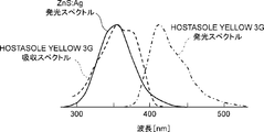
- FIG. 6 is a graph showing the emission spectrum of the inorganic phosphor ZnS: Ag and the absorption and emission spectra of the wavelength conversion phosphor HOSTASOLE YELLOW 3G.
- the scintillation emission spectrum of the inorganic phosphor and the absorption spectrum of the wavelength conversion phosphor have a large overlap.
- alpha rays were incident on the plastic scintillation fiber according to Example 3, a sufficient amount of light could be observed at the tip 10 m away.
- BBOT 2,5-bis- (5-t-butyl-benzoxazoyl) thiophene
- a wavelength conversion fiber having a diameter of 770 ⁇ m composed of a clad layer 3 made of polymethylmethacrylate (refractive index 1.49) having a thickness of 45 ⁇ m was prepared.
- a paint prepared by dissolving 7% by mass of an acrylic resin and 3% by mass of fine particles of the neutron phosphor LiCaAlF 6 : Eu in 90% by mass of methyl ethyl ketone was applied to the surface of the wavelength conversion fiber by a dip method and dried.
- the outermost layer 1 having a thickness of 115 ⁇ m was formed, and the plastic scintillation fiber having an outer diameter of 1000 ⁇ m according to Example 4 was obtained.
- a neutron beam was incident on the plastic scintillation fiber according to Example 4, a sufficient amount of light could be observed at the tip 10 m away.
Landscapes
- Physics & Mathematics (AREA)
- Chemical & Material Sciences (AREA)
- Engineering & Computer Science (AREA)
- General Physics & Mathematics (AREA)
- Health & Medical Sciences (AREA)
- Life Sciences & Earth Sciences (AREA)
- High Energy & Nuclear Physics (AREA)
- Molecular Biology (AREA)
- Spectroscopy & Molecular Physics (AREA)
- Optics & Photonics (AREA)
- Organic Chemistry (AREA)
- Materials Engineering (AREA)
- Manufacturing & Machinery (AREA)
- Ophthalmology & Optometry (AREA)
- Mechanical Engineering (AREA)
- Inorganic Chemistry (AREA)
- Measurement Of Radiation (AREA)
- Light Guides In General And Applications Therefor (AREA)
Abstract
本発明の一態様に係るプラスチックシンチレーションファイバは、少なくとも中性子線及び重粒子線の一方の照射によってシンチレーション光を発する蛍光体を含む最外周層(1)と、最外周層(1)の内部に設けられており、シンチレーション光を吸収して長波長に波長変換する少なくとも1種以上の蛍光体を含むコア(2)と、コア(2)の外周面を覆うと共に、コア(2)よりも低い屈折率を有するクラッド層(3)と、を備えている。コア(2)とクラッド層(3)とが波長変換ファイバを構成し、当該波長変換ファイバの外周面を覆う最外周層(1)とが一体形成されている。
Description
本発明は、プラスチックシンチレーションファイバ及びその製造方法に関する。
従来のプラスチックシンチレーションファイバ(PSF:Plastic Scintillating Fiber)は、シンチレータであるコアの外周面が、コアよりも低屈折率のクラッド層に覆われたプラスチックファイバであり、主に放射線検出に用いられる。通常、コアは、例えばポリスチレンやポリビニルトルエンなどの芳香環を有する基材に、有機系蛍光体を添加した高分子材から構成される。クラッド層は、例えばポリメチルメタクリレートやフッ素含有のポリメチルメタクリレートなどの低屈折率高分子材から構成される。
プラスチックシンチレーションファイバを用いた放射線検出の原理について説明する。シンチレーションファイバのコア基材は芳香環を有しており、照射された放射線がシンチレーションファイバを横断すると、コア内での二次粒子などの再放射などでエネルギーの一部を吸収し、紫外線として放出するという特徴を持つ。この紫外線は、コア基材に蛍光体が添加されていなければ、コア基材自身に自己吸収され、コア内で伝送されずに消失する。
プラスチックシンチレーションファイバでは、この紫外線がコア基材に添加された蛍光体に吸収され、より長波長の光が再放出される。そのため、適切な蛍光体を選択することにより、コア基材に自己吸収され難い、例えば青色などの長波長の光に変換し、ファイバ内で伝送する。ファイバ内で伝送された光は、一端又は両端に接続された検出器において検出される。
このように、シンチレーションファイバは、放射線検出による発光と光伝送の2つの機能を兼ね備えており、放射線の通過位置を算出する用途などで使用されている。このようなシンチレーションファイバでは、コアから放出される紫外光をいかに高効率に長波長に波長変換させ、長距離伝送するかが重要である。
一方、シンチレーションファイバと並んで多用されるのがプラスチック波長変換ファイバ(WLSF:Wavelength Shifting Fiber)である。波長変換ファイバは、例えば青色発光するプラスチックシンチレータなどと組み合わせて使用される。板状又は棒状のプラスチックシンチレータに溝や穴を設けて、青色光を吸収し緑色光に変換する波長変換ファイバを埋め込む。
大型で大面積の検出器では、個々のシンチレータから距離が離れた外部の光電検出器(例えば光電子増倍管など)まで光伝送するのは、光の減衰や空間的な制約から困難な場合がある。このような場合、細くて曲がり易く長距離伝送可能な波長変換ファイバが好適に用いられる。外部の光電検出器まで、多数本の波長変換ファイバを自由にレイアウトできる。
波長変換ファイバのコアはポリスチレンやポリメチルメタクリレート樹脂からなり、波長変換用の蛍光体が溶解されている。波長変換ファイバでは、外部のシンチレータから入射したシンチレーション光をコア内の蛍光体によって吸収し、効率よく波長変換すると共に、ファイバ内で伝送する。波長変換ファイバと組み合わせるシンチレータとしては、プラスチックシンチレータに限らず、中性子等に高感度な無機シンチレータなどが用いられる。
このように、波長変換ファイバによって、大面積あるいは長尺のシンチレータや、中性子検出用等の特殊なシンチレータから発するシンチレーション光を簡単に集光できる。また、波長変換ファイバによって、コアで波長変換した光を伝送し、光電検出器まで自由に接続できる。
ここで、中性子線や重粒子線(例えばアルファ線など)の検出は、プラスチックのみから構成されたプラスチックシンチレータでは感度が低く、難しいため、例えば無機シンチレータが用いられる。無機シンチレータとしては、特許文献1に開示されたものや、6LiF/ZnS:Ag、LiI:Eu2+、LiBaF3:Ce3+、LiCaAlF6:Ce3+、Li2B4O7:Cu+など多数知られている。
しかしながら、無機シンチレータは、減衰長が数mmと透明性が高くなく、発光光(すなわちシンチレーション光)を長距離伝送できない。また、結晶サイズの制約もあるため、無機シンチレータによって光電検出器まで光伝送することは難しい。
また、特許文献2、3などに開示されているように、無機シンチレータを粉砕した微粒子を透明樹脂に分散させたシートが、中性子や重粒子線の検出用に開発されている。このようなシートでは、無機シンチレータと透明樹脂との屈折率差が大きく、透明性が確保できず、シート自身では光電検出器まで効率的に光伝送できない。
そのため、特許文献2、3、4などでは、波長変換ファイバをシンチレータの端面や表面に沿わせ、波長変換ファイバによって光電検出器まで光伝送している。波長変換ファイバを用いることによって、検出光をより長距離伝送できる。
ここで、特許文献2、3、4においてはいずれも、特に特許文献3に開示されたイメージ検出のような空間分解能を重視した検出では、シンチレータと波長変換ファイバとを組み合わせる後加工が多数必要となる。
ここで、特許文献2、3、4においてはいずれも、特に特許文献3に開示されたイメージ検出のような空間分解能を重視した検出では、シンチレータと波長変換ファイバとを組み合わせる後加工が多数必要となる。
従来のプラスチックシンチレーションファイバでは、コア自身においてシンチレーション発光させると共に、光電検出器まで光伝送するため、コアに高い透明性が要求される。そのため、中性子線や重粒子線の照射によってシンチレーション光を発する材料をコアに含ませることによって、中性子線や重粒子線を検出するためのプラスチックシンチレーションファイバを得ることはできない。
同様に、波長変換ファイバでも、外部のシンチレータから照射されたシンチレーション光をコアにおいて波長変換すると共に光伝送するため、コアに高い透明性が要求される。そのため、中性子線や重粒子線の照射によってシンチレーション光を発する材料をコアに含ませることによって、中性子線や重粒子線を検出するためのプラスチックシンチレーションファイバを得ることはできない。
他方、波長変換ファイバを用いた従来のシンチレーション検出器では、シンチレータと波長変換ファイバとを組み合わせる後加工が必要である。さらに、イメージ検出する場合、多数の波長変換ファイバ毎にシンチレータも1つずつ分離して組み合わせる必要があり、加工が著しく難しくなる。
本発明は、このような事情に鑑みなされたものであって、少なくとも中性子線及び重粒子線の一方を検出可能であって、生産性に優れたプラスチックシンチレーションファイバを提供することを目的とする。
本発明の一態様に係るプラスチックシンチレーションファイバは、
少なくとも中性子線及び重粒子線の一方の照射によってシンチレーション光を発する材料を含む最外周層と、
前記最外周層の内部に設けられており、前記シンチレーション光を吸収して長波長に波長変換する少なくとも1種類の蛍光体を含むコアと、
前記コアの外周面を覆うと共に、前記コアよりも低い屈折率を有するクラッド層と、を備え、
前記コア及び前記クラッド層を含む波長変換ファイバと、当該波長変換ファイバの外周面を覆う前記最外周層とが一体形成されている。
少なくとも中性子線及び重粒子線の一方の照射によってシンチレーション光を発する材料を含む最外周層と、
前記最外周層の内部に設けられており、前記シンチレーション光を吸収して長波長に波長変換する少なくとも1種類の蛍光体を含むコアと、
前記コアの外周面を覆うと共に、前記コアよりも低い屈折率を有するクラッド層と、を備え、
前記コア及び前記クラッド層を含む波長変換ファイバと、当該波長変換ファイバの外周面を覆う前記最外周層とが一体形成されている。
本発明の一態様に係るプラスチックシンチレーションファイバでは、中性子線や重粒子線の照射に伴い、最外周層においてシンチレーション光が発生し、当該シンチレーション光を内部のコアが吸収して波長変換すると共に光伝送する。そのため、従来のプラスチックシンチレーションファイバでは感度が低く、検出し難かった中性子線や重粒子線を検出できる。また、コア及びクラッド層を含む波長変換ファイバと、当該波長変換ファイバの外周面を覆う最外周層とが一体形成されているため、従来必要だったシンチレータと波長変換ファイバとを組み合わせる後加工が不要となる。すなわち、少なくとも中性子線及び重粒子線の一方を検出可能であって、生産性に優れたプラスチックシンチレーションファイバを提供できる。
前記材料が、無機蛍光体の微粒子であって、前記最外周層が、前記微粒子を分散させた透明樹脂からなってもよい。中性子線や重粒子線を高感度に検出できる。
また、前記波長変換ファイバと前記最外周層とが、線引き加工によって一体形成されていてもよい。生産性がより向上する。
さらに、前記クラッド層が、インナークラッド層と、前記インナークラッド層の外周面を覆うと共に、前記インナークラッド層よりも低い屈折率を有するアウタークラッド層とを含むマルチクラッド構造を有していてもよい。全反射角が広くなり、より高発光となる。
本発明の一態様に係るプラスチックシンチレーションファイバの製造方法は、
少なくとも中性子線及び重粒子線の一方の照射によってシンチレーション光を発する蛍光体を含む最外周層と、
前記最外周層の内部に設けられており、前記シンチレーション光を吸収して長波長に波長変換する少なくとも1種類の蛍光体を含むコアと、
前記コアの外周面を覆うと共に、前記コアよりも低い屈折率を有するクラッド層と、を備えたプラスチックシンチレーションファイバの製造方法であって、
前記最外周層用の第1円筒体の内部に前記クラッド層用の第2円筒体を挿入し、当該第2円筒体の内部に前記コア用のロッドを挿入し、プリフォームを作製する工程と、
前記プリフォームを加熱しつつ線引き加工する工程と、を備える。
少なくとも中性子線及び重粒子線の一方の照射によってシンチレーション光を発する蛍光体を含む最外周層と、
前記最外周層の内部に設けられており、前記シンチレーション光を吸収して長波長に波長変換する少なくとも1種類の蛍光体を含むコアと、
前記コアの外周面を覆うと共に、前記コアよりも低い屈折率を有するクラッド層と、を備えたプラスチックシンチレーションファイバの製造方法であって、
前記最外周層用の第1円筒体の内部に前記クラッド層用の第2円筒体を挿入し、当該第2円筒体の内部に前記コア用のロッドを挿入し、プリフォームを作製する工程と、
前記プリフォームを加熱しつつ線引き加工する工程と、を備える。
本発明の一態様に係るプラスチックシンチレーションファイバの製造方法は、
少なくとも中性子線及び重粒子線の一方の照射によってシンチレーション光を発する蛍光体を含む最外周層と、
前記最外周層の内部に設けられており、前記シンチレーション光を吸収して長波長に波長変換する少なくとも1種類の蛍光体を含む高屈折率のコアと、
前記コアの外周面を覆うと共に、前記コアよりも低い屈折率を有するクラッド層と、を備えたプラスチックシンチレーションファイバの製造方法であって、
前記クラッド層の表面に、前記最外周層をコーティングする。
少なくとも中性子線及び重粒子線の一方の照射によってシンチレーション光を発する蛍光体を含む最外周層と、
前記最外周層の内部に設けられており、前記シンチレーション光を吸収して長波長に波長変換する少なくとも1種類の蛍光体を含む高屈折率のコアと、
前記コアの外周面を覆うと共に、前記コアよりも低い屈折率を有するクラッド層と、を備えたプラスチックシンチレーションファイバの製造方法であって、
前記クラッド層の表面に、前記最外周層をコーティングする。
本発明により、少なくとも中性子線及び重粒子線の一方を検出可能であって、生産性に優れたプラスチックシンチレーションファイバを提供できる。
以下、本発明を適用した具体的な実施の形態について、図面を参照しながら詳細に説明する。但し、本発明が以下の実施の形態に限定される訳ではない。また、説明を明確にするため、以下の記載及び図面は、適宜、簡略化されている。
(実施の形態1)
<プラスチックシンチレーションファイバの構成>
図1を参照して、本発明の実施の形態1に係るプラスチックシンチレーションファイバについて説明する。図1は、実施の形態1に係るプラスチックシンチレーションファイバの断面図である。
図1に示すように、実施の形態1に係るプラスチックシンチレーションファイバは、最外周層1、コア2、クラッド層3を備えている。
<プラスチックシンチレーションファイバの構成>
図1を参照して、本発明の実施の形態1に係るプラスチックシンチレーションファイバについて説明する。図1は、実施の形態1に係るプラスチックシンチレーションファイバの断面図である。
図1に示すように、実施の形態1に係るプラスチックシンチレーションファイバは、最外周層1、コア2、クラッド層3を備えている。
最外周層1は、少なくとも中性子線及び重粒子線(例えばアルファ線)の一方によってシンチレーション発光する材料を含む樹脂からなる。例えば、最外周層1は、中性子線や重粒子線によってシンチレーション発光する無機蛍光体(無機シンチレータ)の微粒子が分散された透明樹脂(透明有機重合体)からなる。
最外周層1は、シンチレーション光がクラッド層3を貫通して中心部のコア2へ入射する程度に、十分に発光すると共に透明であればよく、高い透明性は要求されないが、できる限り透明で薄い方が望ましい。仮にシンチレータ層である最外周層1の透明性は低くても、光伝送を担う中心部のコア2が高い透明性を有していれば、長距離伝送が可能となる。
コア2は、最外周層1の内部に設けられており、最外周層1において発生したシンチレーション光を吸収してより長波長に変換する少なくとも1種類の蛍光体を含む高屈折率の透明樹脂からなる。コア2を構成する透明樹脂の屈折率は1.5以上が好ましい。
クラッド層3は、コア2の外周面を覆うと共に、コア2よりも低屈折率の透明樹脂からなる。ここで、コア2及びクラッド層3から構成された波長変換ファイバと、当該波長変換ファイバの外周面を覆う最外周層1とが一体形成されている。
光ファイバとして長距離伝送を行うためには、コア2の透明性と同じくクラッド層3の透明性も重要である。長距離伝送のためには、最外周層1の透明性はさほど重要でない。
光ファイバとして長距離伝送を行うためには、クラッド層3の厚さは、伝送光がコア2からクラッド層3に染み出すエバネッセント波の深さより十分厚い3μmから100μmが好ましい。クラッド層3の厚さがクラッド層3に染み出すエバネッセント波の深さより十分厚ければ、クラッド層3と最外周層1の屈折率は同じもの、さらには同一の透明樹脂でもよい。
クラッド層3は、コア2の外周面を覆うと共に、コア2よりも低屈折率の透明樹脂からなる。ここで、コア2及びクラッド層3から構成された波長変換ファイバと、当該波長変換ファイバの外周面を覆う最外周層1とが一体形成されている。
光ファイバとして長距離伝送を行うためには、コア2の透明性と同じくクラッド層3の透明性も重要である。長距離伝送のためには、最外周層1の透明性はさほど重要でない。
光ファイバとして長距離伝送を行うためには、クラッド層3の厚さは、伝送光がコア2からクラッド層3に染み出すエバネッセント波の深さより十分厚い3μmから100μmが好ましい。クラッド層3の厚さがクラッド層3に染み出すエバネッセント波の深さより十分厚ければ、クラッド層3と最外周層1の屈折率は同じもの、さらには同一の透明樹脂でもよい。
コア2が含む蛍光体としては、最外周層1において発生したシンチレーション光の波長に吸収スペクトルが適合すると共に、波長変換する蛍光スペクトルが吸収スペクトルからできる限り離れたものが望ましい。さらに、光電子増倍管(PMT)やアバランシェフォトダイオード(APD)などの光電検出器の波長感度に合わせるなどのため、さらに波長変換させる第2の蛍光体をコア2が含んでもよい。なお、蛍光体の詳細については後述する。
実施の形態1に係るプラスチックシンチレーションファイバでは、中性子線や重粒子線の照射に伴い、最外周層1においてシンチレーション光が発生し、当該シンチレーション光を内部のコア2が吸収して波長変換すると共に光伝送する。そのため、従来のプラスチックシンチレーションファイバでは感度が低く、検出し難かった中性子線や重粒子線を高感度に検出できる。すなわち、実施の形態1に係るプラスチックシンチレーションファイバは、中性子線や重粒子線のシンチレーション機能と波長変換機能とを兼ね備えた複合型のプラスチック光ファイバである。
また、コア2及びクラッド層3から構成された波長変換ファイバと、当該波長変換ファイバの外周面を覆う最外周層1とが一体形成されている。そのため、従来必要だったシンチレータと波長変換ファイバとを組み合わせる後加工が不要であり、従来に比べ、飛躍的に生産性が向上すると共にコストも低減できる。
<プラスチックシンチレーションファイバの変形例>
図2は、実施の形態1の変形例に係るプラスチックシンチレーションファイバの断面図である。変形例に係るプラスチックシンチレーションファイバは、クラッド層3をインナークラッド層として、さらにクラッド層4をアウタークラッド層として備えている。すなわち、クラッド層が、インナークラッド層(クラッド層3)とアウタークラッド層(クラッド層4)とを含むマルチクラッド構造を有している。クラッド層4は、クラッド層3の外周面を覆うと共に、クラッド層3よりも低屈折率の透明樹脂からなる。
図2は、実施の形態1の変形例に係るプラスチックシンチレーションファイバの断面図である。変形例に係るプラスチックシンチレーションファイバは、クラッド層3をインナークラッド層として、さらにクラッド層4をアウタークラッド層として備えている。すなわち、クラッド層が、インナークラッド層(クラッド層3)とアウタークラッド層(クラッド層4)とを含むマルチクラッド構造を有している。クラッド層4は、クラッド層3の外周面を覆うと共に、クラッド層3よりも低屈折率の透明樹脂からなる。
ここで、コア2で波長変換された再発光光はコア2内で立体角的に等方的に放射される。そのため、コア2とクラッド層3もしくはクラッド層4との屈折率差に基づいた全反射角以内の光しかファイバ方向に伝送できない。変形例に係るプラスチックシンチレーションファイバは、クラッド層3に加え、低屈折率のクラッド層4を備えるため、図1のプラスチックシンチレーションファイバよりも全反射角が広くなり(開口数NAが大きくなり)、より高発光になる。
<最外周層1の材料>
シンチレータ層である最外周層1は、少なくとも中性子線及び重粒子線(アルファ線など)の一方の照射によってシンチレーション発光する材料(蛍光体)を含む樹脂からなる。例えば、最外周層1は、中性子線や重粒子線によってシンチレーション発光する無機蛍光体の微粒子が均一又は不均一に分散された透明樹脂からなる。
シンチレータ層である最外周層1は、少なくとも中性子線及び重粒子線(アルファ線など)の一方の照射によってシンチレーション発光する材料(蛍光体)を含む樹脂からなる。例えば、最外周層1は、中性子線や重粒子線によってシンチレーション発光する無機蛍光体の微粒子が均一又は不均一に分散された透明樹脂からなる。
最外周層1を構成する透明樹脂は、加熱によって細く線引きが可能なように、熱可塑性であることが好ましい。このような透明樹脂としては、メチルメタクリレートなどで代表されるメタクリル酸エステルモノマー群、メチルアクリレートに代表されるアクリル酸エステルモノマー群及びスチレンに代表されるビニル基を持った芳香族モノマー群のいずれかからなる単独重合体、もしくは共重合体が好適である。
最外周層1を構成する透明樹脂の屈折率は、光伝送性能の観点からは限定されないが、分散させる無機蛍光体の屈折率に近いものが好ましい。分散させる無機蛍光体と分散媒体である透明樹脂との屈折率差が大きいと、光散乱が大きくなり、最外周層1において発生したシンチレーション光がコア2まで有効に届かないからである。
最外周層1に含まれる無機蛍光体の微粒子としては、無機蛍光体の結晶を粉砕したものが好適に用いられる。特に、特許文献1及び2に記載されたような無機蛍光体であれば、ガンマ線に感度がなく中性子線のみによって選択的に発光するので好ましい場合がある。
一例として、最外周層1は、リチウム6を含みEuがドープされ、中性子線によってシンチレーション発光する無機蛍光体LiCaAlF6:Euの微粒子を透明樹脂に1~30質量%分散させたものである。この無機蛍光体の微粒子を分散させる透明樹脂は、コア2もしくはクラッド層3、4などと同じものから好適に選択できる。この最外周層1は、中性子線によって350~400nmの紫外光をシンチレーション発光する。
最外周層1の他の例としては、重粒子線(アルファ線など)によってシンチレーション発光する無機蛍光体ZnS:Agの微粒子を透明樹脂に分散させたものを挙げられる。この無機蛍光体の微粒子を分散させる透明樹脂も、コア2もしくはクラッド層3、4などと同じものから好適に選択できる。この最外周層1は、重粒子線によって400~500nmの可視光を発光する。
透明樹脂に分散させる無機蛍光体の粒子径は0.1~100μmが好ましく、1~10μmがさらに好ましい。分散させる無機蛍光体の濃度は、1~50質量%が好ましく、5~30質量%がさらに好ましい。濃度が低過ぎると、最外周層1における中性子線や重粒子線による発光効率が悪化する。濃度が高過ぎると、透明樹脂への分散が困難になったり、加熱による線引きが困難になったりする。
なお、分散させる無機蛍光体は検出対象とする中性子線や重粒子線によって適宜選択され、上記に限定されない。また、無機蛍光体の粒子径や濃度も検出性能、製造の難易度などによって適宜選択され、上記に限定されない。さらに、分散させる透明樹脂も分散性や製造の容易などによって適宜選択され、上記に限定されない。
<コア2の材料>
コア2に用いられる材料は、透明樹脂であれば、制約はない。中でもメチルメタクリレートに代表されるメタクリル酸エステルモノマー群、メチルアクリレートに代表されるアクリル酸エステルモノマー群及びスチレンに代表されるビニル基を持った芳香族モノマー群のいずれかからなる単独重合体、もしくは共重合体が好適である。
コア2に用いられる材料は、透明樹脂であれば、制約はない。中でもメチルメタクリレートに代表されるメタクリル酸エステルモノマー群、メチルアクリレートに代表されるアクリル酸エステルモノマー群及びスチレンに代表されるビニル基を持った芳香族モノマー群のいずれかからなる単独重合体、もしくは共重合体が好適である。
中でも、ビニル基を持った芳香族モノマーからなる重合体が、高い屈折率を有し、好ましい。コア2とクラッド層3との屈折率差が大きくなり、全反射角が広くなる。すなわち、コア2内で波長変換された光のうち、より広い角度の光を伝送できるため、より高発光のシンチレーションファイバが得られる。
コア2に含まれる波長変換蛍光体は、芳香環を有し、かつ共鳴可能な構造を有する有機蛍光体であって、コア2に単分子溶解することが好ましい。代表的な蛍光体としては、250~350nmを吸収する2-(4-t-ブチルフェニル)-5-(4-ビフェニル)-1,3,4-オキサジアゾール(b-PBD)、2-(4-ビフェニル)-5-フェニル-1,3,4-オキサジアゾール(PBD)、パラターフェニル(PTP)、パラクォーターフェニル(PQP)、2,5-ジフェニルオキサゾール(PPO)、1-フェニル-3-(2,4,6-トリメチルフェニル)-2-ピラゾリン(PMP)、3-ヒドロキシフラボン(3HF)、などが挙げられる。
また、350~400nmを吸収する4,4’-ビス-(2,5-ジメチルスチリル)-ジフェニル(BDB)、2,5-ビス-(5-t-ブチル-ベンゾキサゾイル)チオフェン(BBOT)、1,4-ビス-(2-(5-フェニロキサゾリル))ベンゼン(POPOP)、1,4-ビス-(4-メチル-5-フェニル-2-オキサゾリル)ベンゼン(DMPOPOP)、1,4-ジフェニル-1,3-ブタジエン(DPB)、1,6-ジフェニル-1,3,5-ヘキサトリエン(DPH)なども好ましい。
さらに、具体例として、400~500nmを吸収するHOSTASOLE YELLOW 3G、MACROLEX FLUORESCENT YELLOW 10GN、Kayaset Yellow SF-G、500~600nmを吸収するLUMOGEN F ORANGE 240、LUMOGEN F RED 300などが挙げられる。
高発光を得るには、コア2に含まれる波長変換蛍光体の吸収スペクトルと、最外周層1に含まれる無機蛍光体の発光スペクトルとの重なりが大きいことが好ましい。
上述の波長変換蛍光体を単体で使用してもよいし、複数の波長変換蛍光体を併用してもよい。各波長変換蛍光体では、量子収率が高く、吸収スペクトルと発光スペクトルの重なりが少ない(ストークスシフトが大きい)ことが好ましい。プラスチックファイバの特性として、長波長である程、可視光は伝送損失が小さいため、より長波長で発光する波長変換蛍光体が好ましく、適宜2種以上併用してもよい。波長変換蛍光体は、コア2を構成する透明樹脂に可溶であることが好ましい。
上述の波長変換蛍光体を単体で使用してもよいし、複数の波長変換蛍光体を併用してもよい。各波長変換蛍光体では、量子収率が高く、吸収スペクトルと発光スペクトルの重なりが少ない(ストークスシフトが大きい)ことが好ましい。プラスチックファイバの特性として、長波長である程、可視光は伝送損失が小さいため、より長波長で発光する波長変換蛍光体が好ましく、適宜2種以上併用してもよい。波長変換蛍光体は、コア2を構成する透明樹脂に可溶であることが好ましい。
波長変換蛍光体の濃度は、単独でも複数でも質量濃度で50~10000ppmが好適であり、さらには100~1000ppmが好ましい。濃度が低過ぎると、最外周層1からのシンチレーション光をコア2において効率よく吸収できない。逆に、濃度が高過ぎると、蛍光体自身が持つ自己吸収の影響が大きくなって、波長変換効率が低下したり、変換された光に対する透過率が低下して減衰長が悪化する。
<クラッド層3の材料>
クラッド層3に用いられる材料は、コア2より低屈折率を有する透明樹脂であれば、制約はない。中でも、メチルメタクリレートに代表されるメタクリル酸エステルモノマー群及びパーフルオロアルキルメタクリレート等のフッ素化モノマー群、メチルアクリレートに代表されるアクリル酸エステルモノマー群及びパーフルオロアルキルアクリレート等のフッ素化モノマー群のいずれかを原料とする単独重合体もしくは共重合体が好適である。
クラッド層3に用いられる材料は、コア2より低屈折率を有する透明樹脂であれば、制約はない。中でも、メチルメタクリレートに代表されるメタクリル酸エステルモノマー群及びパーフルオロアルキルメタクリレート等のフッ素化モノマー群、メチルアクリレートに代表されるアクリル酸エステルモノマー群及びパーフルオロアルキルアクリレート等のフッ素化モノマー群のいずれかを原料とする単独重合体もしくは共重合体が好適である。
<クラッド層4の材料>
クラッド層4に用いられる材料は、クラッド層3よりさらに低屈折率を有する透明樹脂であればよい。クラッド層3のモノマー群などからから選択できる。特に、低屈折率を有する含フッ素モノマー群から選択することが好ましい。
クラッド層4に用いられる材料は、クラッド層3よりさらに低屈折率を有する透明樹脂であればよい。クラッド層3のモノマー群などからから選択できる。特に、低屈折率を有する含フッ素モノマー群から選択することが好ましい。
これらのモノマー群は熱又は光照射により容易に重合体又は共重合体が得られるため、精密な組成分布を形成でき、かつ取り扱い易いという利点がある。重合にあたっては有機過酸化物又はアゾ化合物を重合開始剤として加えてもよい。代表的な有機過酸化物としては1,1,3,3-テトラメチルブチルパーオキシ-2-エチルヘキサノエート、n-ブチル-4,4-ビス(t-ブチルパーオキシ)バレレート、1,1-ビス(t-ブチルパーオキシ)シクロヘキサン等が挙げられるが、熱又は光照射によってラジカルを生成するものであれば特に制限はない。
また分子量調整のために連鎖移動剤としてメルカプタンを添加してもよい。代表的なメルカプタンとしてはオクチルメルカプタンがあるが、R-SH(ここでRは有機基を表す)の構造を有するものであれば特に制限はない。
<プラスチックシンチレーションファイバの製造方法>
図3は、実施の形態1に係るプラスチックシンチレーションファイバの製造方法を示す斜視図である。図3は、図1に示したプラスチックシンチレーションファイバを製造するための母材(プリフォーム)を示す。
図3は、実施の形態1に係るプラスチックシンチレーションファイバの製造方法を示す斜視図である。図3は、図1に示したプラスチックシンチレーションファイバを製造するための母材(プリフォーム)を示す。
第1円筒体11は、少なくとも中性子線及び重粒子線の一方によってシンチレーション発光する無機蛍光体の微粒子を分散させた熱可塑性樹脂からなる円筒体である。第1円筒体11は、線引き加工後に最外周層1を構成する。第1円筒体11の製造方法の詳細については後述する。
ロッド12は、シンチレーション光を吸収して長波長に波長変換する少なくとも1種類の蛍光体を溶解させた透明な熱可塑性樹脂からなる円柱体である。ロッド12は、線引き加工後にコア2を構成する。
第2円筒体13は、ロッド12より低い屈折率を有し、透明な熱可塑性樹脂からなる円筒体である。第2円筒体13は、線引き加工後にクラッド層3を構成する。
第2円筒体13は、ロッド12より低い屈折率を有し、透明な熱可塑性樹脂からなる円筒体である。第2円筒体13は、線引き加工後にクラッド層3を構成する。
図3に示すように、第1円筒体11の内部に第2円筒体13を挿入すると共に、第2円筒体13の内部にロッド12を挿入し、プリフォームを作製する。図3は、ロッド12を第2円筒体13の内部に挿入している途中の様子を示している。作製されたプリフォームの先端を加熱しながら、例えば外径1mmに線引きすることによって、実施の形態1に係るプラスチックシンチレーションファイバが得られる。
なお、図3に示すように、第1円筒体11、第2円筒体13、及びロッド12の間には隙間が形成されているが、減圧下において線引き加工を行うため、コア2、クラッド層3、及び最外周層1は、密着して一体形成される。
図2に示した変形例に係るプラスチックシンチレーションファイバも、同様の製造方法によって製造できる。
図2に示した変形例に係るプラスチックシンチレーションファイバも、同様の製造方法によって製造できる。
実施の形態1に係るプラスチックシンチレーションファイバの製造方法では、中性子線や重粒子線によって発光するシンチレータ層(最外周層1)を波長変換ファイバ(コア2及びクラッド層3)の外周面に一体形成する。そのため、当該プラスチックシンチレーションファイバは、中性子線や重粒子線を検出可能であると共に光伝送可能である。すなわち、当該プラスチックシンチレーションファイバは、単体で、従来のシンチレータ及び波長変換ファイバの機能を兼ね備えている。
そのため、従来必要だったシンチレータと波長変換ファイバとを組み合わせる後加工が不要であり、従来に比べ、生産性が向上すると共にコストも低減できる。特に、イメージ検出する場合、波長変換ファイバ毎にシンチレータも1つずつ分離して組み合わせる必要がなく、当該プラスチックシンチレーションファイバを並べるだけよい。そのため、従来に比べ、飛躍的に生産性が向上すると共にコストも低減できる。
なお、波長変換ファイバ(コア2及びクラッド層3)を製造した後、シンチレータ層(最外周層1)を蒸着、ディップコート、スプレーコートなどのコーティング(塗装を含む)によって一体形成してもよい。本方法により、少なくとも中性子線及び重粒子線(アルファ線など)の一方の照射によってシンチレーション発光する材料(蛍光体)をより高濃度で添加できる。
<プラスチックシンチレーションファイバの応用例>
次に図4を参照して、実施の形態1に係るプラスチックシンチレーションファイバの応用例について説明する。図4は、実施の形態1に係るプラスチックシンチレーションファイバの応用例を示す斜視図である。当該応用例では、実施の形態1に係るプラスチックシンチレーションファイバPSFが、基板上にアレイ状に配列されている。
なお、当然のことながら、図4に示した右手系xyz直交座標は、構成要素の位置関係を説明するための便宜的なものである。通常、z軸正向きが鉛直上向き、xy平面が水平面である。
次に図4を参照して、実施の形態1に係るプラスチックシンチレーションファイバの応用例について説明する。図4は、実施の形態1に係るプラスチックシンチレーションファイバの応用例を示す斜視図である。当該応用例では、実施の形態1に係るプラスチックシンチレーションファイバPSFが、基板上にアレイ状に配列されている。
なお、当然のことながら、図4に示した右手系xyz直交座標は、構成要素の位置関係を説明するための便宜的なものである。通常、z軸正向きが鉛直上向き、xy平面が水平面である。
各プラスチックシンチレーションファイバPSFには、光電子増倍管などの光電検出器が接続されており(不図示)、伝送された光を検出できる。このような構成によって、例えば1mm分解能で1次元のイメージ検出が可能となる。ここで、分解能はプラスチックシンチレーションファイバPSFの直径に等しい。さらに、このようなプラスチックシンチレーションファイバPSFのアレイを2段設け、互いに直交させて上下に重ねて配置すれば、2次元のイメージ検出も実現できる。
このように、空間分解能が高い中性子線や重粒子線のイメージ検出も、本実施の形態に係るプラスチックシンチレーションファイバを用いることによって、簡易かつ低コストに実現できる。
以下、本発明を実施例によりさらに詳細に説明するが、本発明は係る実施例により何ら限定されない。
<実施例1>
リチウム6を含みEuがドープされ、中性子線によってシンチレーション発光する無機蛍光体LiCaAlF6:Euの微粒子をポリメチルメタクリレートに混錬した後、外径50mm、内径40mmの最外周層用円筒体(図3の第1円筒体11)を成形した。微粒子の平均粒径は6.2μm、微粒子の濃度は22質量%とした。
リチウム6を含みEuがドープされ、中性子線によってシンチレーション発光する無機蛍光体LiCaAlF6:Euの微粒子をポリメチルメタクリレートに混錬した後、外径50mm、内径40mmの最外周層用円筒体(図3の第1円筒体11)を成形した。微粒子の平均粒径は6.2μm、微粒子の濃度は22質量%とした。
ポリスチレン(屈折率1.59)からなる直径32mmのコア用ロッド(図3のロッド12)と、ポリメチルメタクリレート(屈折率1.49)からなる外径38mm、内径34mmのクラッド層用円筒体(図3の第2円筒体13)とを準備した。コア用ロッドには、波長変換蛍光体として、2,5-ビス-(5-t-ブチル-ベンゾキサゾイル)チオフェン(BBOT)を200質量ppmの濃度で溶解させた。
図3に示すように、最外周層用円筒体の内部にクラッド層用円筒体を挿入すると共に、クラッド層用円筒体の内部にコア用ロッドを挿入し、プリフォームを作製した。このプリフォームの先端を加熱しながら、減圧下で外径が1mmとなるように一体線引きし、実施例1に係るプラスチックシンチレーションファイバを得た。このプラスチックシンチレーションファイバは、図1に示した断面構成を有している。外径は1000μm、クラッド層3の直径は770μm、コア2の直径は680μm、最外周層1の厚みは115μm、クラッド層3の厚みは45μmであった。
図5は、中性子蛍光体LiCaAlF6:Euの発光スペクトル、波長変換蛍光体BBOTの吸収及び発光スペクトルを示すグラフである。図5に示すように、中性子蛍光体のシンチレーション発光スペクトルと波長変換蛍光体の吸収スペクトルとの重なりが大きい。実施例1に係るプラスチックシンチレーションファイバに中性子線を入射したところ、10m離れた先端において十分な光量を観察できた。
<実施例2>
実施例1と同様に、外径50mm、内径40mmの最外周層用円筒体(図3の第1円筒体11)を成形した。また、実施例1と同様に、ポリスチレン(屈折率1.59)からなる直径28mmのコア用ロッド(図3のロッド12)と、ポリメチルメタクリレート(屈折率1.49)からなる外径33mm、内径30mmのインナークラッド層用円筒体(図3の第2円筒体13)とを準備した。コア用ロッドには、波長変換蛍光体として、BBOTを300質量ppmの濃度で溶解させた。
実施例1と同様に、外径50mm、内径40mmの最外周層用円筒体(図3の第1円筒体11)を成形した。また、実施例1と同様に、ポリスチレン(屈折率1.59)からなる直径28mmのコア用ロッド(図3のロッド12)と、ポリメチルメタクリレート(屈折率1.49)からなる外径33mm、内径30mmのインナークラッド層用円筒体(図3の第2円筒体13)とを準備した。コア用ロッドには、波長変換蛍光体として、BBOTを300質量ppmの濃度で溶解させた。
さらに、実施例2では、パーフルオロアルキルアクリレート等のフッ素化モノマーの共重合体(屈折率1.42)からなる外径38mm、内径35mmのアウタークラッド層用円筒体(不図示)を準備した。アウタークラッド層用円筒体は、線引き加工後に図2に示したクラッド層4を構成する。
そして、最外周層用円筒体の内部にアウタークラッド層用円筒体を挿入し、その内部にインナークラッド層用円筒体を挿入し、その内部にコア用ロッドを挿入することによって、プリフォームを作製した。
そして、最外周層用円筒体の内部にアウタークラッド層用円筒体を挿入し、その内部にインナークラッド層用円筒体を挿入し、その内部にコア用ロッドを挿入することによって、プリフォームを作製した。
このプリフォームの先端を加熱しながら、減圧下で外径が1mmとなるように一体線引きし、実施例2に係るプラスチックシンチレーションファイバを得た。このプラスチックシンチレーションファイバは、図2に示した断面構成を有している。外径は1000μm、クラッド層4の外径は754μm、クラッド層3の外径は682μm、コア2の直径は612μm、最外周層1の厚みは123μm、クラッド層4の厚みは36μm、クラッド層3の厚みは35μmであった。
実施例2に係るプラスチックシンチレーションファイバに中性子線を入射したところ、10m離れた先端において実施例1より30%ほど高い光量を観察できた。コア2の直径は実施例1より小さくなったものの、より低屈折のクラッド層4を設けたことによって、全反射角が広くなり、より高発光になったものと考えられる。
<実施例3>
アルファ線などの重粒子線によってシンチレーション発光する無機蛍光体ZnS:Agの微粒子をポリメチルメタクリレートに混錬した後、外径50mm、内径40mmの最外周層用円筒体(図3の第1円筒体11)を成形した。微粒子の平均粒径は5.3μm、微粒子の濃度は25質量%とした。
アルファ線などの重粒子線によってシンチレーション発光する無機蛍光体ZnS:Agの微粒子をポリメチルメタクリレートに混錬した後、外径50mm、内径40mmの最外周層用円筒体(図3の第1円筒体11)を成形した。微粒子の平均粒径は5.3μm、微粒子の濃度は25質量%とした。
ポリスチレン(屈折率1.59)からなる直径32mmのコア用ロッド(図3のロッド12)と、ポリメチルメタクリレート(屈折率1.49)からなる外径38mm、内径34mmのクラッド層用円筒体(図3の第2円筒体13)とを準備した。コア用ロッドには、波長変換蛍光体として、HOSTASOLE YELLOW 3Gを300質量ppmの濃度で溶解させた。
図3に示すように、最外周層用円筒体の内部にクラッド層用円筒体を挿入すると共に、クラッド層用円筒体の内部にコア用ロッドを挿入し、プリフォームを作製した。このプリフォームの先端を加熱しながら、減圧下で外径が1mmとなるように一体線引きし、実施例3に係るプラスチックシンチレーションファイバを得た。このプラスチックシンチレーションファイバは、図1に示した断面構成を有している。外径は1000μm、クラッド層3の直径は770μm、コア2の直径は680μm、最外周層1の厚みは115μm、クラッド層3の厚みは45μmであった。
図6は、無機蛍光体ZnS:Agの発光スペクトル、波長変換蛍光体HOSTASOLE YELLOW 3Gの吸収及び発光スペクトルを示すグラフである。図6に示すように、無機蛍光体のシンチレーション発光スペクトルと波長変換蛍光体の吸収スペクトルとの重なりが大きい。実施例3に係るプラスチックシンチレーションファイバにアルファ線を入射したところ、10m離れた先端において十分な光量を観察できた。
<実施例4>
波長変換蛍光体として、2,5-ビス-(5-t-ブチル-ベンゾキサゾイル)チオフェン(BBOT)を200質量ppmの濃度で含有したポリスチレン(屈折率1.59)からなる直径680μmのコア2と、厚み45μmのポリメチルメタクリレート(屈折率1.49)からなるクラッド層3とから構成された直径770μmの波長変換ファイバを準備した。この波長変換ファイバの表面に、アクリル樹脂7質量%と中性子蛍光体LiCaAlF6:Euの微粒子3質量%とをメチルエチルケトン90質量%に溶解した塗料をディップ法により塗布し、乾燥させた。これによって、厚み115μmの最外周層1が形成され、実施例4に係る外径1000μmのプラスチックシンチレーションファイバを得た。実施例4に係るプラスチックシンチレーションファイバに中性子線を入射したところ、10m離れた先端において十分な光量を観察できた。
波長変換蛍光体として、2,5-ビス-(5-t-ブチル-ベンゾキサゾイル)チオフェン(BBOT)を200質量ppmの濃度で含有したポリスチレン(屈折率1.59)からなる直径680μmのコア2と、厚み45μmのポリメチルメタクリレート(屈折率1.49)からなるクラッド層3とから構成された直径770μmの波長変換ファイバを準備した。この波長変換ファイバの表面に、アクリル樹脂7質量%と中性子蛍光体LiCaAlF6:Euの微粒子3質量%とをメチルエチルケトン90質量%に溶解した塗料をディップ法により塗布し、乾燥させた。これによって、厚み115μmの最外周層1が形成され、実施例4に係る外径1000μmのプラスチックシンチレーションファイバを得た。実施例4に係るプラスチックシンチレーションファイバに中性子線を入射したところ、10m離れた先端において十分な光量を観察できた。
本発明は上記実施の形態に限られず、趣旨を逸脱しない範囲で適宜変更可能である。
この出願は、2019年10月31日に出願された日本出願特願2019-198101を基礎とする優先権を主張し、その開示の全てをここに取り込む。
1 最外周層
2 コア
3 クラッド層(インナークラッド層)
4 クラッド層(アウタークラッド層)
11 第1円筒体
12 ロッド
13 第2円筒体
PSF プラスチックシンチレーションファイバ
2 コア
3 クラッド層(インナークラッド層)
4 クラッド層(アウタークラッド層)
11 第1円筒体
12 ロッド
13 第2円筒体
PSF プラスチックシンチレーションファイバ
Claims (6)
- 少なくとも中性子線及び重粒子線の一方の照射によってシンチレーション光を発する材料を含む最外周層と、
前記最外周層の内部に設けられており、前記シンチレーション光を吸収して長波長に波長変換する少なくとも1種類の蛍光体を含むコアと、
前記コアの外周面を覆うと共に、前記コアよりも低い屈折率を有するクラッド層と、を備え、
前記コア及び前記クラッド層を含む波長変換ファイバと、当該波長変換ファイバの外周面を覆う前記最外周層とが一体形成されている、
プラスチックシンチレーションファイバ。 - 前記材料が、無機蛍光体の微粒子であって、
前記最外周層が、前記微粒子を分散させた透明樹脂からなる、
請求項1に記載のプラスチックシンチレーションファイバ。 - 前記波長変換ファイバと前記最外周層とが、線引き加工によって一体形成されている、
請求項1又は2に記載のプラスチックシンチレーションファイバ。 - 前記クラッド層が、
インナークラッド層と、
前記インナークラッド層の外周面を覆うと共に、前記インナークラッド層よりも低い屈折率を有するアウタークラッド層と、を含むマルチクラッド構造を有している、
請求項1~3のいずれか一項に記載のプラスチックシンチレーションファイバ。 - 少なくとも中性子線及び重粒子線の一方の照射によってシンチレーション光を発する蛍光体を含む最外周層と、
前記最外周層の内部に設けられており、前記シンチレーション光を吸収して長波長に波長変換する少なくとも1種類の蛍光体を含むコアと、
前記コアの外周面を覆うと共に、前記コアよりも低い屈折率を有するクラッド層と、を備えたプラスチックシンチレーションファイバの製造方法であって、
前記最外周層用の第1円筒体の内部に前記クラッド層用の第2円筒体を挿入し、当該第2円筒体の内部に前記コア用のロッドを挿入し、プリフォームを作製する工程と、
前記プリフォームを加熱しつつ線引き加工する工程と、を備えた、
プラスチックシンチレーションファイバの製造方法。 - 少なくとも中性子線及び重粒子線の一方の照射によってシンチレーション光を発する蛍光体を含む最外周層と、
前記最外周層の内部に設けられており、前記シンチレーション光を吸収して長波長に波長変換する少なくとも1種類の蛍光体を含む高屈折率のコアと、
前記コアの外周面を覆うと共に、前記コアよりも低い屈折率を有するクラッド層と、を備えたプラスチックシンチレーションファイバの製造方法であって、
前記クラッド層の表面に、前記最外周層をコーティングする、
プラスチックシンチレーションファイバの製造方法。
Priority Applications (4)
| Application Number | Priority Date | Filing Date | Title |
|---|---|---|---|
| CN202080074049.5A CN114600013A (zh) | 2019-10-31 | 2020-10-27 | 塑料闪烁光纤及其制造方法 |
| JP2021553616A JPWO2021085401A1 (ja) | 2019-10-31 | 2020-10-27 | |
| US17/773,278 US20230040697A1 (en) | 2019-10-31 | 2020-10-27 | Plastic scintillating fiber and its manufacturing method |
| EP20881303.0A EP4053856A4 (en) | 2019-10-31 | 2020-10-27 | Plastic scintillating fiber and production method therefor |
Applications Claiming Priority (2)
| Application Number | Priority Date | Filing Date | Title |
|---|---|---|---|
| JP2019198101 | 2019-10-31 | ||
| JP2019-198101 | 2019-10-31 |
Publications (1)
| Publication Number | Publication Date |
|---|---|
| WO2021085401A1 true WO2021085401A1 (ja) | 2021-05-06 |
Family
ID=75715988
Family Applications (1)
| Application Number | Title | Priority Date | Filing Date |
|---|---|---|---|
| PCT/JP2020/040174 Ceased WO2021085401A1 (ja) | 2019-10-31 | 2020-10-27 | プラスチックシンチレーションファイバ及びその製造方法 |
Country Status (5)
| Country | Link |
|---|---|
| US (1) | US20230040697A1 (ja) |
| EP (1) | EP4053856A4 (ja) |
| JP (1) | JPWO2021085401A1 (ja) |
| CN (1) | CN114600013A (ja) |
| WO (1) | WO2021085401A1 (ja) |
Families Citing this family (1)
| Publication number | Priority date | Publication date | Assignee | Title |
|---|---|---|---|---|
| CN119602102A (zh) * | 2024-11-20 | 2025-03-11 | 华北电力大学 | 一种用于空气开关柜弧光保护的荧光光纤安装装置 |
Citations (8)
| Publication number | Priority date | Publication date | Assignee | Title |
|---|---|---|---|---|
| JPH09236669A (ja) * | 1996-03-01 | 1997-09-09 | Tohoku Electric Power Co Inc | ファイバ型放射線検出器 |
| JP2011141239A (ja) | 2010-01-08 | 2011-07-21 | Japan Atomic Energy Agency | ピクセル型二次元イメージ検出器 |
| JP2012126854A (ja) | 2010-12-16 | 2012-07-05 | Tokuyama Corp | 中性子用シンチレーターおよび中性子検出器 |
| JP2015072227A (ja) | 2013-10-04 | 2015-04-16 | 独立行政法人日本原子力研究開発機構 | 中性子検出器 |
| JP2015513075A (ja) * | 2012-02-14 | 2015-04-30 | アメリカン サイエンス アンド エンジニアリング,インコーポレイテッドAmerican Science and Engineering,Inc. | 波長シフトファイバ結合シンチレーション検出器を用いるx線検査 |
| JP2018200172A (ja) * | 2017-05-25 | 2018-12-20 | 株式会社クラレ | プラスチック波長変換ファイバ及びその製造方法 |
| JP2019148538A (ja) * | 2018-02-28 | 2019-09-05 | 株式会社クラレ | 高線量場プラスチックシンチレーションファイバー及びその製造方法 |
| JP2019198101A (ja) | 2011-09-09 | 2019-11-14 | エルジー エレクトロニクス インコーポレイティド | インタ予測方法及びその装置 |
Family Cites Families (8)
| Publication number | Priority date | Publication date | Assignee | Title |
|---|---|---|---|---|
| FR2718852B1 (fr) * | 1994-04-19 | 1996-05-15 | Commissariat Energie Atomique | Dispositif de détection à distance de rayonnement. |
| JP3771058B2 (ja) * | 1998-08-18 | 2006-04-26 | 株式会社ワイヤードジャパン | 放射線検出システム |
| CN102183812A (zh) * | 2011-02-21 | 2011-09-14 | 北京大学 | 一种闪烁—移波光纤及快中子转换屏 |
| CN110146913A (zh) * | 2019-05-10 | 2019-08-20 | 南开大学 | 一种用于超长距离辐射传感的双包层闪烁光纤结构 |
| EP4006124B1 (en) * | 2019-07-30 | 2026-01-28 | Kuraray Co., Ltd. | Plastic wavelength conversion fiber |
| EP4215949A4 (en) * | 2020-09-16 | 2024-08-28 | Kuraray Co., Ltd. | PLASTIC SCINTILLATION FIBER AND METHOD FOR PRODUCING SAME |
| CN116324519B (zh) * | 2020-10-15 | 2026-04-17 | 株式会社可乐丽 | 塑料闪烁光纤及其制造方法 |
| CN116324514B (zh) * | 2020-10-15 | 2026-03-17 | 株式会社可乐丽 | 塑料闪烁光纤及其制造方法 |
-
2020
- 2020-10-27 EP EP20881303.0A patent/EP4053856A4/en not_active Withdrawn
- 2020-10-27 CN CN202080074049.5A patent/CN114600013A/zh active Pending
- 2020-10-27 WO PCT/JP2020/040174 patent/WO2021085401A1/ja not_active Ceased
- 2020-10-27 US US17/773,278 patent/US20230040697A1/en not_active Abandoned
- 2020-10-27 JP JP2021553616A patent/JPWO2021085401A1/ja active Pending
Patent Citations (8)
| Publication number | Priority date | Publication date | Assignee | Title |
|---|---|---|---|---|
| JPH09236669A (ja) * | 1996-03-01 | 1997-09-09 | Tohoku Electric Power Co Inc | ファイバ型放射線検出器 |
| JP2011141239A (ja) | 2010-01-08 | 2011-07-21 | Japan Atomic Energy Agency | ピクセル型二次元イメージ検出器 |
| JP2012126854A (ja) | 2010-12-16 | 2012-07-05 | Tokuyama Corp | 中性子用シンチレーターおよび中性子検出器 |
| JP2019198101A (ja) | 2011-09-09 | 2019-11-14 | エルジー エレクトロニクス インコーポレイティド | インタ予測方法及びその装置 |
| JP2015513075A (ja) * | 2012-02-14 | 2015-04-30 | アメリカン サイエンス アンド エンジニアリング,インコーポレイテッドAmerican Science and Engineering,Inc. | 波長シフトファイバ結合シンチレーション検出器を用いるx線検査 |
| JP2015072227A (ja) | 2013-10-04 | 2015-04-16 | 独立行政法人日本原子力研究開発機構 | 中性子検出器 |
| JP2018200172A (ja) * | 2017-05-25 | 2018-12-20 | 株式会社クラレ | プラスチック波長変換ファイバ及びその製造方法 |
| JP2019148538A (ja) * | 2018-02-28 | 2019-09-05 | 株式会社クラレ | 高線量場プラスチックシンチレーションファイバー及びその製造方法 |
Non-Patent Citations (1)
| Title |
|---|
| See also references of EP4053856A4 |
Also Published As
| Publication number | Publication date |
|---|---|
| EP4053856A4 (en) | 2023-11-29 |
| JPWO2021085401A1 (ja) | 2021-05-06 |
| EP4053856A1 (en) | 2022-09-07 |
| US20230040697A1 (en) | 2023-02-09 |
| CN114600013A (zh) | 2022-06-07 |
Similar Documents
| Publication | Publication Date | Title |
|---|---|---|
| JP7629467B2 (ja) | プラスチックシンチレーションファイバ及びその製造方法 | |
| JP7645899B2 (ja) | プラスチックシンチレーションファイバ及びその製造方法 | |
| EP3557288B1 (en) | Method of producing a plastic scintillation fiber | |
| JP7048349B2 (ja) | 高線量場プラスチックシンチレーションファイバー及びその製造方法 | |
| JP6902549B2 (ja) | 高線量場プラスチックシンチレーションファイバー及びその製造方法 | |
| JP6833611B2 (ja) | プラスチック波長変換ファイバ及びその製造方法 | |
| JP7394073B2 (ja) | 低透過性放射線検出プラスチックシンチレーションファイバ | |
| JP7645894B2 (ja) | プラスチックシンチレーションファイバ及びその製造方法 | |
| CN114600013A (zh) | 塑料闪烁光纤及其制造方法 | |
| JP2010169674A (ja) | 放射線検出器 | |
| JP7808060B2 (ja) | プラスチック波長変換ファイバ及びその製造方法 | |
| JP7428714B2 (ja) | プラスチック波長変換ファイバ | |
| CN120468991A (zh) | 液体闪烁光纤及其制备方法 |
Legal Events
| Date | Code | Title | Description |
|---|---|---|---|
| 121 | Ep: the epo has been informed by wipo that ep was designated in this application |
Ref document number: 20881303 Country of ref document: EP Kind code of ref document: A1 |
|
| ENP | Entry into the national phase |
Ref document number: 2021553616 Country of ref document: JP Kind code of ref document: A |
|
| NENP | Non-entry into the national phase |
Ref country code: DE |
|
| ENP | Entry into the national phase |
Ref document number: 2020881303 Country of ref document: EP Effective date: 20220531 |