WO2021090557A1 - 送風機 - Google Patents
送風機 Download PDFInfo
- Publication number
- WO2021090557A1 WO2021090557A1 PCT/JP2020/032538 JP2020032538W WO2021090557A1 WO 2021090557 A1 WO2021090557 A1 WO 2021090557A1 JP 2020032538 W JP2020032538 W JP 2020032538W WO 2021090557 A1 WO2021090557 A1 WO 2021090557A1
- Authority
- WO
- WIPO (PCT)
- Prior art keywords
- shaft
- fan
- blower
- motor
- main plate
- Prior art date
- Legal status (The legal status is an assumption and is not a legal conclusion. Google has not performed a legal analysis and makes no representation as to the accuracy of the status listed.)
- Ceased
Links
Images



Classifications
-
- F—MECHANICAL ENGINEERING; LIGHTING; HEATING; WEAPONS; BLASTING
- F04—POSITIVE - DISPLACEMENT MACHINES FOR LIQUIDS; PUMPS FOR LIQUIDS OR ELASTIC FLUIDS
- F04D—NON-POSITIVE-DISPLACEMENT PUMPS
- F04D29/00—Details, component parts, or accessories
- F04D29/70—Suction grids; Strainers; Dust separation; Cleaning
- F04D29/701—Suction grids; Strainers; Dust separation; Cleaning especially adapted for elastic fluid pumps
- F04D29/703—Suction grids; Strainers; Dust separation; Cleaning especially adapted for elastic fluid pumps specially for fans, e.g. fan guards
-
- F—MECHANICAL ENGINEERING; LIGHTING; HEATING; WEAPONS; BLASTING
- F04—POSITIVE - DISPLACEMENT MACHINES FOR LIQUIDS; PUMPS FOR LIQUIDS OR ELASTIC FLUIDS
- F04D—NON-POSITIVE-DISPLACEMENT PUMPS
- F04D29/00—Details, component parts, or accessories
- F04D29/26—Rotors specially for elastic fluids
- F04D29/28—Rotors specially for elastic fluids for centrifugal or helico-centrifugal pumps for radial-flow or helico-centrifugal pumps
- F04D29/281—Rotors specially for elastic fluids for centrifugal or helico-centrifugal pumps for radial-flow or helico-centrifugal pumps for fans or blowers
- F04D29/282—Rotors specially for elastic fluids for centrifugal or helico-centrifugal pumps for radial-flow or helico-centrifugal pumps for fans or blowers the leading edge of each vane being substantially parallel to the rotation axis
-
- F—MECHANICAL ENGINEERING; LIGHTING; HEATING; WEAPONS; BLASTING
- F04—POSITIVE - DISPLACEMENT MACHINES FOR LIQUIDS; PUMPS FOR LIQUIDS OR ELASTIC FLUIDS
- F04D—NON-POSITIVE-DISPLACEMENT PUMPS
- F04D17/00—Radial-flow pumps, e.g. centrifugal pumps; Helico-centrifugal pumps
- F04D17/08—Centrifugal pumps
- F04D17/16—Centrifugal pumps for displacing without appreciable compression
-
- F—MECHANICAL ENGINEERING; LIGHTING; HEATING; WEAPONS; BLASTING
- F04—POSITIVE - DISPLACEMENT MACHINES FOR LIQUIDS; PUMPS FOR LIQUIDS OR ELASTIC FLUIDS
- F04D—NON-POSITIVE-DISPLACEMENT PUMPS
- F04D25/00—Pumping installations or systems
- F04D25/02—Units comprising pumps and their driving means
- F04D25/06—Units comprising pumps and their driving means the pump being electrically driven
-
- F—MECHANICAL ENGINEERING; LIGHTING; HEATING; WEAPONS; BLASTING
- F04—POSITIVE - DISPLACEMENT MACHINES FOR LIQUIDS; PUMPS FOR LIQUIDS OR ELASTIC FLUIDS
- F04D—NON-POSITIVE-DISPLACEMENT PUMPS
- F04D25/00—Pumping installations or systems
- F04D25/02—Units comprising pumps and their driving means
- F04D25/08—Units comprising pumps and their driving means the working fluid being air, e.g. for ventilation
-
- F—MECHANICAL ENGINEERING; LIGHTING; HEATING; WEAPONS; BLASTING
- F04—POSITIVE - DISPLACEMENT MACHINES FOR LIQUIDS; PUMPS FOR LIQUIDS OR ELASTIC FLUIDS
- F04D—NON-POSITIVE-DISPLACEMENT PUMPS
- F04D29/00—Details, component parts, or accessories
- F04D29/05—Shafts or bearings, or assemblies thereof, specially adapted for elastic fluid pumps
- F04D29/056—Bearings
-
- F—MECHANICAL ENGINEERING; LIGHTING; HEATING; WEAPONS; BLASTING
- F04—POSITIVE - DISPLACEMENT MACHINES FOR LIQUIDS; PUMPS FOR LIQUIDS OR ELASTIC FLUIDS
- F04D—NON-POSITIVE-DISPLACEMENT PUMPS
- F04D29/00—Details, component parts, or accessories
- F04D29/08—Sealings
- F04D29/083—Sealings especially adapted for elastic fluid pumps
-
- F—MECHANICAL ENGINEERING; LIGHTING; HEATING; WEAPONS; BLASTING
- F04—POSITIVE - DISPLACEMENT MACHINES FOR LIQUIDS; PUMPS FOR LIQUIDS OR ELASTIC FLUIDS
- F04D—NON-POSITIVE-DISPLACEMENT PUMPS
- F04D29/00—Details, component parts, or accessories
- F04D29/26—Rotors specially for elastic fluids
- F04D29/28—Rotors specially for elastic fluids for centrifugal or helico-centrifugal pumps for radial-flow or helico-centrifugal pumps
- F04D29/281—Rotors specially for elastic fluids for centrifugal or helico-centrifugal pumps for radial-flow or helico-centrifugal pumps for fans or blowers
-
- F—MECHANICAL ENGINEERING; LIGHTING; HEATING; WEAPONS; BLASTING
- F04—POSITIVE - DISPLACEMENT MACHINES FOR LIQUIDS; PUMPS FOR LIQUIDS OR ELASTIC FLUIDS
- F04D—NON-POSITIVE-DISPLACEMENT PUMPS
- F04D29/00—Details, component parts, or accessories
- F04D29/26—Rotors specially for elastic fluids
- F04D29/28—Rotors specially for elastic fluids for centrifugal or helico-centrifugal pumps for radial-flow or helico-centrifugal pumps
- F04D29/281—Rotors specially for elastic fluids for centrifugal or helico-centrifugal pumps for radial-flow or helico-centrifugal pumps for fans or blowers
- F04D29/282—Rotors specially for elastic fluids for centrifugal or helico-centrifugal pumps for radial-flow or helico-centrifugal pumps for fans or blowers the leading edge of each vane being substantially parallel to the rotation axis
- F04D29/283—Rotors specially for elastic fluids for centrifugal or helico-centrifugal pumps for radial-flow or helico-centrifugal pumps for fans or blowers the leading edge of each vane being substantially parallel to the rotation axis rotors of the squirrel-cage type
-
- F—MECHANICAL ENGINEERING; LIGHTING; HEATING; WEAPONS; BLASTING
- F04—POSITIVE - DISPLACEMENT MACHINES FOR LIQUIDS; PUMPS FOR LIQUIDS OR ELASTIC FLUIDS
- F04D—NON-POSITIVE-DISPLACEMENT PUMPS
- F04D29/00—Details, component parts, or accessories
- F04D29/40—Casings; Connections of working fluid
- F04D29/42—Casings; Connections of working fluid for radial or helico-centrifugal pumps
- F04D29/4206—Casings; Connections of working fluid for radial or helico-centrifugal pumps especially adapted for elastic fluid pumps
- F04D29/4226—Fan casings
-
- H—ELECTRICITY
- H02—GENERATION; CONVERSION OR DISTRIBUTION OF ELECTRIC POWER
- H02K—DYNAMO-ELECTRIC MACHINES
- H02K5/00—Casings; Enclosures; Supports
- H02K5/04—Casings or enclosures characterised by the shape, form or construction thereof
-
- H—ELECTRICITY
- H02—GENERATION; CONVERSION OR DISTRIBUTION OF ELECTRIC POWER
- H02K—DYNAMO-ELECTRIC MACHINES
- H02K5/00—Casings; Enclosures; Supports
- H02K5/04—Casings or enclosures characterised by the shape, form or construction thereof
- H02K5/10—Casings or enclosures characterised by the shape, form or construction thereof with arrangements for protection from ingress, e.g. water or fingers
-
- H—ELECTRICITY
- H02—GENERATION; CONVERSION OR DISTRIBUTION OF ELECTRIC POWER
- H02K—DYNAMO-ELECTRIC MACHINES
- H02K7/00—Arrangements for handling mechanical energy structurally associated with dynamo-electric machines, e.g. structural association with mechanical driving motors or auxiliary dynamo-electric machines
- H02K7/14—Structural association with mechanical loads, e.g. with hand-held machine tools or fans
Definitions
- This disclosure relates to a blower equipped with a fan and a motor.
- Patent Document 1 discloses a sirocco fan used for cooling an in-vehicle battery or the like. In the sirocco fan described in Patent Document 1, vibration and noise are reduced by improving the assembly accuracy of the fan.
- the present disclosure has been made to solve such a problem, and an object of the present disclosure is to provide a blower capable of reducing the intrusion of minute foreign matter into the bearing of the motor.
- one aspect of the blower according to the present disclosure is a blower including a fan and a motor, wherein the motor includes a shaft including a shaft, a bearing supporting the shaft, and at least a part of the bearing. It has a motor case that covers it.
- the fan has a first surface facing the motor case and a second surface facing the first surface, and is erected on a main plate connected to the shaft and a second surface of the main plate, and includes the shaft. It has a plurality of blades arranged radially with respect to the axis.
- At least one of the fan and the motor case has one or more blocking members. One or more blocking members are located between the first surface of the main plate and the motor case in a radial direction orthogonal to the axis, and surround the shaft.
- the fan may have a boss that is attached to the outer surface of the shaft and supports the shaft.
- the distance between the boss and the motor case is more than 0 mm, preferably 2.5 mm or less.
- the one or more blocking members may have an annular shape.
- one or more blocking members may have a cylindrical shape.
- the one or more blocking members may include a plurality of blocking members having different distances from the axis.
- the main plate is formed with one or more through holes penetrating between the first surface and the second surface between the axis included by the shaft and the area where a plurality of blades are erected. Is preferable.
- one or more blocking members are arranged at a position closer to the shaft than one or more through holes.
- the motor case may have a side surface that extends along the extending direction of the shaft of the motor and surrounds the shaft. It is preferable that one or more blocking members are arranged at positions facing the side surfaces of the motor case.
- the main plate may have a conical surface shape.
- the fan may have one or more blocking members.
- FIG. 1 is a perspective view showing the appearance of the blower according to the first embodiment.
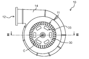
- FIG. 2 is a top view showing the appearance of the blower according to the first embodiment.
- FIG. 3 is a cross-sectional view showing the internal structure of the blower according to the first embodiment.
- FIG. 4 is a first perspective view showing the appearance of the fan according to the first embodiment.
- FIG. 5 is a second perspective view showing the appearance of the fan according to the first embodiment.
- FIG. 6 is a partial cross-sectional view showing the internal structure of the blower according to the comparative example.
- FIG. 7 is a diagram showing analysis results of each blower according to the comparative example and the first embodiment.
- FIG. 8 is a partial cross-sectional view showing the internal structure of the blower according to the second embodiment.
- FIG. 9 is a diagram showing the analysis results of each blower according to the comparative example and the second embodiment.
- FIGS. 1 to 3. are a perspective view and a top view showing the appearance of the blower 10 according to the first embodiment, respectively.
- FIG. 3 is a cross-sectional view showing the internal structure of the blower 10 according to the first embodiment.
- FIG. 3 shows a cross section taken along the line III-III shown in FIG. 2, in other words, a cross section when cut in a plane passing through the axis C of the shaft 51 included in the blower 10.
- the blower 10 shown in FIGS. 1 and 2 is a sirocco fan that blows out the gas sucked from the suction port 11 from the outlet 12.
- the blower 10 includes a case 14, a fan 30, and a motor 50, as shown in FIG. The blower 10 sucks gas from the suction port 11 and blows it out from the air outlet 12 by rotating the fan 30 by the motor 50.
- the case 14 is an instrument that serves as an outer shell of the blower 10.
- a suction port 11 and an outlet 12 are formed in the case 14.
- the fan 30 and the motor 50 are arranged inside the case 14.
- the motor 50 is fixed to the bottom of the case 14.
- the fan 30 is fixed to the shaft 51 of the motor 50.
- the suction port 11 formed in the case 14 is arranged on the axis C (that is, the rotation shaft of the motor 50) included in the shaft 51.
- the air outlet 12 is arranged at a position radially away from the axis C.
- the radial direction means a direction orthogonal to the axis C.
- the material forming the case 14 is not particularly limited, and may be, for example, polybutylene terephthalate (PBT, Polybutylene Terephthate), polycarbonate (PC, Polycarbonate), polypropylene (PP, Polypolylone), or a mixed material thereof. ..
- the motor 50 is a device that rotates the fan 30. As shown in FIG. 3, the motor 50 has a shaft 51, a bearing 52, and a motor case 54. The motor 50 further includes a rotor 56 and a stator 58. The motor 50 is not particularly limited as long as it is a motor having a shaft 51, a bearing 52, and a motor case 54, but in the present embodiment, it is an inner rotor type brushless motor.
- the shaft 51 is a columnar member that rotates with respect to the motor case 54.
- the material forming the shaft 51 is not particularly limited, but may be, for example, a metal such as stainless steel.
- the bearing 52 is a member that supports the shaft 51.
- the bearing 52 has a substantially cylindrical shape.
- the inner surface of the bearing 52 is attached to the outer surface of the shaft 51 along the axial C direction in which the shaft 51 extends.
- the outer surface of the bearing 52 is fixed to the motor case 54.
- the bearing 52 can reduce the rotational resistance of the shaft 51 to the motor case 54.
- a sintered oil-impregnated bearing can be used as the bearing 52.
- the motor case 54 is a housing that covers at least a part of the bearing 52.
- the motor case 54 covers a part of the shaft 51, a bearing 52, a rotor 56, a stator 58, and the like.
- the motor case 54 is fixed to the case 14.
- the material forming the motor case 54 is not particularly limited, but may be, for example, a galvanized steel sheet.
- the motor case 54 includes a top surface 54a, a side surface 54b, a step upper surface 54c, a step side surface 54d, and a bottom surface 54e.
- the top surface 54a is a surface of the fan 30 facing the first surface 32a of the main plate 32.
- the top surface 54a is a surface that intersects the axis C included in the shaft 51.
- the top surface 54a has a substantially circular shape.
- the side surface 54b is a surface extending from the outer edge of the top surface 54a along the direction in which the shaft 51 of the motor 50 extends.
- the side surface 54b has an annular shape surrounding the shaft 51 of the motor 50.
- the side surface 54b has a substantially cylindrical shape.
- the step upper surface 54c extends outward from the end of the side surface 54b on the side far from the fan 30.
- the step upper surface 54c is a surface facing the first surface 32a of the main plate 32 of the fan 30.
- the step upper surface 54c is a flat surface having a substantially annular shape.
- the step side surface 54d is a surface extending in parallel with the shaft 51, which is the rotation axis of the motor 50, from the outer edge of the step upper surface 54c.
- the step side surface 54d has an annular shape surrounding the shaft 51, which is the rotation axis of the motor 50.
- the step side surface 54d has a substantially cylindrical shape.
- the bottom surface 54e is a surface that covers a region surrounded by an end portion on the side of the step side surface 54d that is far from the step top surface 54c.
- the rotor 56 is a member that rotates with respect to the stator 58.
- the rotor 56 is attached to the outer surface of the shaft 51 along the axial direction C of the shaft 51.
- the stator 58 is a member that rotates the rotor 56.
- the stator 58 is arranged around the rotor 56 and fixed to the motor case 54.
- the fan 30 is a component that is connected to the shaft 51 of the motor 50 and rotates about the axis C included in the shaft 51.
- a gas flow from the suction port 11 of the blower 10 to the air outlet 12 is generated.
- the material forming the fan 30 is not particularly limited. However, for example, it may be a resin such as PBT, PC, PP, or a mixed material thereof.
- the fan 30 is made of polypropylene containing about 10% by weight of glass fiber.
- FIG. 4 is a first perspective view showing the appearance of the fan 30 according to the first embodiment.
- FIG. 5 is a second perspective view showing the appearance of the fan 30 according to the first embodiment.
- the fan 30 has a main plate 32, a plurality of blades 34, a boss 41, a blocking member 42, and a blocking member 43.
- the fan 30 further includes an annular member 36 and a reinforcing member 38.
- the main plate 32 has a first surface 32a facing the motor case 54 and a second surface 32b facing the first surface 32a.
- the main plate 32 is a member connected to the shaft 51.
- the main plate 32 is connected to the shaft 51 at its central axis.
- the central axis of the main plate 32 is the rotation axis of the fan 30, and passes through the center of the main plate 32.
- the main plate 32 has a conical surface shape.
- the first surface 32a and the second surface 32b are surfaces located inside and outside the conical main plate 32, respectively. At least a part of the motor case 54 is arranged inside the conical space formed by the main plate 32.
- the main plate 32 has one or more penetrating between the first surface 32a and the second surface 32b between the axis C of the shaft 51 to which the main plate 32 is connected and the area where the plurality of blades 34 are erected.
- Through hole 33 is formed. More specifically, the one or more through holes 33 are arranged between the area where the boss 41 of the main plate 32 is arranged and the area where the plurality of blades 34 are erected.
- a plurality of through holes 33 are formed in the main plate 32.
- the assembling worker of the blower 10 can grip the fan 30 by using the plurality of through holes 33. Therefore, the handling of the fan 30 can be further facilitated.
- the number of through holes 33 is not particularly limited, but in the example shown in FIG. 2, the number of through holes 33 is six.
- the blade 34 is erected on the second surface 32b of the main plate 32.
- the blade 34 is a plate-shaped member that is radially arranged with respect to the axis C (that is, the central axis of the main plate 32) included in the shaft 51.
- the blade 34 may be curved as shown in FIGS. 4 and 5.
- the plurality of blades 34 are arranged along the outer peripheral edge of the main plate 32.
- the annular member 36 is an annular member attached to the end of the plurality of blades 34 on the side opposite to the main plate 32.
- the boss 41 is attached to the outer surface of the shaft 51 of the motor 50.
- the boss 41 is a member fixed to the shaft 51.
- the boss 41 is erected on the first surface 32a of the main plate 32.
- the boss 41 has a cylindrical shape surrounding the axis C included in the shaft 51.
- the distance between the boss 41 and the motor case 54 of the motor 50 is larger than 0 mm. As a result, it is possible to prevent the boss 41 and the motor case 54 from interfering with each other.
- the distance between the boss 41 and the motor case 54 means the length of the gap between the boss 41 and the motor case 54.
- Each of the blocking member 42 and the blocking member 43 is a member that prevents minute foreign substances such as sand from entering the bearing 52 through between the main plate 32 of the fan 30 and the motor case 54.
- Each of the blocking member 42 and the blocking member 43 is arranged between the first surface 32a of the main plate 32 and the motor case 54 so as to be separated from the shaft 51 in the radial direction and surrounds the shaft 51.
- each blocking member surrounds the shaft 51, not only the state in which each blocking member surrounds the entire circumference of the shaft 51 without interruption, but also each blocking member is arranged around the shaft 51 and each A state in which a part of the blocking member is interrupted is also included.
- each blocking member has a substantially annular shape surrounding the shaft 51, and each blocking member is separated into a plurality of portions in the circumferential direction with the axis C included in the shaft 51 as the central axis. You may.
- Each blocking member may be arranged in a range of angles exceeding 50% of the total circumferential angle (360 °) of the circumferential angles of the shaft 51 with the axis C as the central axis. ..
- Each of the blocking member 42 and the blocking member 43 has an annular shape surrounding the shaft 51. More specifically, as shown in FIG. 5, each of the blocking member 42 and the blocking member 43 has a cylindrical shape centered on the rotation axis of the motor 50 (that is, the axis C included in the shaft 51). Has. As shown in FIG. 3, the blocking member 42 and the blocking member 43 have different distances from the axis C included in the shaft 51. Each of the blocking member 42 and the blocking member 43 is arranged so as to be separated from the outer edge of the main plate 32 on the rotation shaft side.
- the reinforcing member 38 is a member that connects the first surface 32a of the main plate 32 and the boss 41.
- the reinforcing member 38 is a plate-shaped member extending in the radial direction from the axis C included in the shaft 51. As a result, it is possible to prevent the boss 41 from coming off the main plate 32.
- FIG. 6 is a partial cross-sectional view showing the internal structure of the blower 910 according to the comparative example.
- FIG. 6 shows a part of the cross section of the shaft 51 included in the blower 910 when cut in a plane passing through the axis C, in the vicinity of the motor 50 and the main plate 32.
- the blower 910 according to the comparative example includes a case 14, a fan 930, and a motor 50.
- the case 14 and the motor 50 of the blower 910 according to the comparative example have the same configurations as the case 14 and the motor 50 of the blower 10 according to the present embodiment, respectively.
- the fan 930 included in the blower 910 according to the comparative example has a main plate 32, a plurality of blades 34, and a boss 141, similarly to the fan 30 according to the present embodiment.
- the main plate 32 and the plurality of blades 34 included in the fan 930 have the same configurations as the main plate 32 and the plurality of blades 34 according to the present embodiment, respectively.
- the boss 141 is different from the boss 41 according to the present embodiment in the length in the rotation axis direction, that is, the axial center C direction, and is the same in other configurations.
- the boss 141 has a shorter length in the rotation axis direction than the boss 41 according to the present embodiment.
- the distance Gb between the boss 141 and the motor case 54 in the blower 910 according to the comparative example is larger than the distance Gb between the boss 41 and the motor case 54 in the blower 10 according to the present embodiment.
- the interval Gb is 2 mm, but in the blower 910 according to the comparative example, the interval Gb is 3 mm.
- the fan 930 according to the comparative example is also different from the fan 30 according to the present embodiment in that it does not include the blocking member 42 and the blocking member 43.
- minute foreign substances such as sand and dust contained in the gas sucked from the suction port 11 are removed from the gap between the fan 930 and the case 14. It can penetrate between the main plate 32 and the motor 50. The minute foreign matter can also enter between the main plate 32 and the motor 50 through the through hole 33 formed in the main plate 32 of the fan 930. The minute foreign matter that has entered between the main plate 32 and the motor 50 can enter the gap between the shaft 51 and the bearing 52 of the motor 50.
- minute foreign matter can enter between the main plate 32 of the fan 930 and the top surface 54a of the motor case 54 of the motor 50.
- the main plate 32 has a conical surface shape
- a relatively large space is formed between the main plate 32 and the top surface 54a of the motor case 54. Therefore, minute foreign matter easily enters between the main plate 32 and the top surface 54a of the motor case 54.
- the fan 30 is arranged between the first surface 32a of the main plate 32 and the motor case 54 in the radial direction so as to be separated from the shaft 51, and the shaft 51. It has a blocking member 42 and a blocking member 43 that surround the circuit.
- the blocking member 42 and the blocking member 43 can form a portion where the gap between the main plate 32 and the motor case 54 is narrow. Therefore, even when minute foreign matter enters between the main plate 32 and the motor 50, at least a part of the minute foreign matter toward the shaft 51 and the bearing 52 can be blocked by each blocking member. Therefore, according to the blower 10 according to the present embodiment, it is possible to reduce the intrusion of minute foreign matter into the bearing 52 of the motor 50.
- each of the blocking member 42 and the blocking member 43 is arranged so as to be separated from the outer edge of the main plate 32 on the rotation shaft side, that is, on the shaft 51 side. Therefore, the minute foreign matter can flow into the space sandwiched between each blocking member and the portion outside the blocking member arranged on the main plate 32. Therefore, it is possible to reduce the inflow of minute foreign matter toward the rotating shaft side from each blocking member.
- Each blocking member has an annular shape surrounding the shaft 51. As a result, it is possible to reduce the intrusion of minute foreign matter into the bearing 52 from all directions with the axis C included in the shaft 51 as the central axis.
- Each blocking member has a cylindrical shape centered on the rotation axis of the motor 50 (axis center C of the shaft 51).
- the shape of the fan 30 can be made axisymmetric with respect to the rotation axis of the motor 50, so that vibration and noise during rotation of the fan 30 can be reduced.
- the fan 30 has two blocking members having different distances from the axis C included in the shaft 51.
- the blocking member 42 having a smaller distance from the rotating shaft causes the minute foreign matter to pass through the gap. It can block minute foreign substances.
- the radial distance from the shaft 51 is small. The small foreign matter can be blocked by the blocking member 42 on the other side.
- Each blocking member is arranged at a position closer to the shaft 51 than the through hole 33. As a result, it is possible to reduce the intrusion of minute foreign matter that has entered between the main plate 32 and the motor 50 through the through hole 33 into the bearing 52.
- the distance Gb between the boss 41 and the motor case 54 is 2 mm, which is narrower than the distance Gb between the boss 141 and the motor case 54 in the comparative example.
- the interval Gb is not limited to 2 mm.
- the interval Gb may be larger than 0 mm and about 2.5 mm or less. As a result, it is possible to reduce minute foreign matter invading the bearing 52 as compared with the case where the interval Gb is 3 mm as in the blower 910 according to the comparative example.
- FIG. 7 is a diagram showing analysis results of each blower according to the comparative example and the first embodiment.
- FIG. 7 also shows the analysis results of the blowers according to the modified examples 1 to 3.
- each blower according to the comparative example and the first embodiment.
- the fluid analysis of the gas sucked in and blown out by each blower was performed.
- the gas contains particles that imitate minute foreign substances, and in the analysis, the position of each particle that moves with the gas was tracked.
- the volume of gas sucked by each blower is 100 m 3 / h, and the rotation speed of each fan is 2350 rpm.
- the particle density is 3 mg / mm 3 .
- the diameter of the particles is distributed within the range of 1 ⁇ m or more and 20 ⁇ m or less.
- the number of particles flowing into each blower is 600,000 / sec.
- the number of particles that reached the cylinder between the boss of each fan and the motor case 54 within 0.13 sec was defined as the amount of particles invading. More specifically, the number of particles that have reached the cylindrical space arranged between the boss and the motor case 54 is defined as the amount of particles invading.
- the central axis of the cylindrical space is the rotation axis of the motor 50 (that is, the shaft 51), the diameter is 18 mm, and the height is equal to the interval Gb.
- the intrusion amount was 73, and in the blower 10 according to the present embodiment, it corresponds to about 7% of the intrusion amount in the blower 910 according to the comparative example.
- the amount of intrusion could be reduced to 5 pieces.
- the blower 10 according to the present embodiment can significantly reduce the amount of invading minute foreign matter as compared with the blower 910 according to the comparative example.
- FIG. 7 also shows the amount of increase in the mass of the fan 30 with respect to the weight of the fan 930 according to such a comparative example.
- the amount of increase in the mass of the fan 30 according to the present embodiment with respect to the mass of the fan 930 of the comparative example is 1.8 g. This amount of increase corresponds to about 2.65% of the total mass of the fan 30 (68 g).
- the blower according to the modified example 1 is a blower in which only the boss 141 of the blower 910 according to the comparative example is replaced with the boss 41 of the blower 10 according to the present embodiment, as shown in the shape column of the modified example 1 in FIG. is there.
- the blower according to the modified example 2 is a blower in which only the blocking member 42 of the blower 10 according to the present embodiment is added to the blower 910 according to the comparative example. ..
- the blower according to the modified example 3 is a blower in which only the blocking member 43 of the blower 10 according to the present embodiment is added to the blower 910 according to the comparative example. ..
- the intrusion amount could be reduced to 23, which corresponds to about 32% of the intrusion amount in the blower 910 according to the comparative example.
- the amount of increase in the mass of the fan according to the modified example 1 with respect to the mass of the fan 930 of the comparative example was 0.1 g. This amount of increase corresponds to about 0.14% of the total mass of the fan 30 (68 g).
- the intrusion amount could be reduced to 16 which corresponds to about 22% of the intrusion amount in the blower 910 according to the comparative example.
- the amount of increase in the mass of the fan according to the modified example 2 is 1.1 g with respect to the mass of the fan 930 of the comparative example. This amount of increase corresponds to about 1.62% of the total mass of the fan 30 (68 g).
- the amount of increase in the mass of the fan according to the modified example 3 is 0.6 g with respect to the mass of the fan 930 of the comparative example. This amount of increase corresponds to about 0.88% of the total mass of the fan 30 (68 g).
- each of the boss 41, the blocking member 42, and the blocking member 43 according to the present embodiment has an effect of reducing the invasion of minute foreign matter into the bearing 52. It was confirmed to have. Further, in the present embodiment, by combining the configurations of the modified examples 1 to 3, it is possible to reduce the invasion of minute foreign matter into the bearing 52 as compared with each of the modified examples 1 to 3. It was confirmed that it could be further enhanced.
- the blower 10 of the present embodiment is a blower 10 including a fan 30 and a motor 50
- the motor 50 includes a shaft 51 including an axis C, a bearing 52 that supports the shaft 51, and a bearing. It has a motor case 54 that covers at least a part of 52.
- the fan 30 has a first surface 32a facing the motor case 54 and a second surface 32b facing the first surface 32a, a main plate 32 connected to the shaft 51, and a second surface of the main plate 32. It has a plurality of blades 34 erected on 32b and arranged radially with respect to the axis C including the shaft 51.
- At least one of the fan 30 and the motor case 54 has one or more blocking members 42, 43.
- One or more blocking members 42, 43 are located between the first surface 32a of the main plate 32 and the motor case 54 in a radial direction orthogonal to the axis, and are separated from the shaft 51, and the shaft 51 Surround.
- the fan 30 may have a boss 41 which is attached to the outer surface of the shaft 51 and supports the shaft 51.
- the motor case 54 may have a side surface 54b that extends along the direction in which the shaft 51 of the motor 50 extends and surrounds the shaft 51.
- the blower according to the second embodiment will be described.
- the blower according to the present embodiment is different from the blower 10 according to the first embodiment mainly in the configuration of the blocking member included in the fan.
- the following blower according to the present embodiment will be described focusing on the difference from the blower 10 according to the first embodiment.
- FIG. 8 is a partial cross-sectional view showing the internal structure of the blower 110 according to the second embodiment.
- FIG. 8 shows a part of the cross section in the vicinity of the motor 50 and the main plate 32 when cut in a plane passing through the axis C included in the shaft 51 included in the blower 110.
- the blower 110 according to the present embodiment includes a case 14, a fan 130, and a motor 50.
- the case 14 and the motor 50 of the blower 110 according to the present embodiment have the same configurations as the case 14 and the motor 50 of the blower 10 according to the first embodiment, respectively.
- the fan 130 of the blower 110 has a main plate 32, a plurality of blades 34, and a boss 141, similarly to the fan 30 according to the first embodiment.
- the main plate 32 and the plurality of blades 34 included in the fan 130 have the same configurations as the main plate 32 and the plurality of blades 34 according to the first embodiment, respectively.
- the boss 141 has the same configuration as the boss 141 of the fan 930 according to the above-described comparative example. That is, the boss 141 has a shorter length than the boss 41 according to the first embodiment in the rotation axis direction of the motor 50, that is, in the axial center C direction of the shaft 51.
- the fan 130 according to the present embodiment further has a blocking member 144. Similar to the respective blocking members according to the first embodiment, the blocking member 144 is arranged between the first surface 32a of the main plate 32 and the motor case 54 at a distance from the shaft 51 in the radial direction. Surrounds the shaft 51.
- the blocking member 144 according to the present embodiment is arranged at a position facing the side surface 54b of the motor case 54. Further, the blocking member 144 has an annular shape surrounding the shaft 51. More specifically, the blocking member 144 has a cylindrical shape centered on the rotation axis of the motor 50.
- the blocking member 144 is arranged at a position far from the shaft 51 from the through hole 33 in the radial direction. Further, the blocking member 144 is arranged at a position closer to the shaft 51 than the step side surface 54d of the motor case 54 in the radial direction.
- blower 110 according to the present embodiment has the blocking member 144, the same effect as that of each blocking member according to the first embodiment can be obtained.
- a maze structure (labyrinth) is formed between the main plate 32 of the fan 130 and the motor case 54.
- the blocking member 144 is arranged at a position closer to the shaft 51 than the step side surface 54d in the radial direction. As a result, the blocking member 144 is arranged above the step upper surface 54c connected to the step side surface 54d, so that a further maze structure is formed between the step upper surface 54c and the blocking member 144. By forming such a maze structure, it is possible to further reduce the invasion of minute foreign matter into the vicinity of the rotating shaft, that is, the vicinity of the bearing 52.
- the blocking member 144 has an annular shape surrounding the shaft 51. As a result, it is possible to reduce the invasion of minute foreign matter toward the bearing 52 from all directions with the axis C included in the shaft 51 as the central axis.
- the blocking member 144 has a cylindrical shape with the rotation axis of the motor 50 as the central axis.
- the blocking member 144 has a cylindrical shape centered on the axis C included in the shaft 51.
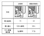
- FIG. 9 is a diagram showing the analysis results of each blower according to the comparative example and the second embodiment.
- FIG. 9 shows the result of analysis under the same conditions as the analysis conditions of the blower 10 according to the first embodiment described above.
- the intrusion amount was 73 pieces.
- the intrusion amount could be reduced to 44, which corresponds to about 60% of the intrusion amount in the blower 910 according to the comparative example.
- the blower 110 according to the present embodiment can significantly reduce the amount of invading minute foreign matter as compared with the blower 910 according to the comparative example.
- the fan has a blocking member.
- the motor case 54 included in the motor 50 may have a blocking member, or both the fan and the motor case 54 may each have a blocking member. That is, at least one of the fan and the motor case 54 may have one or more blocking members.
- the fan 30 has two blocking members 42 and 43.
- the number of blocking members is not limited to two, and may be one or more.
- the number of blocking members may be one.
- the fan 30 had two blocking members having different radial distances from the axis C included in the shaft 51.
- the shaft 51 may have three or more blocking members having different distances from the axis C. That is, the fan 30 may have a plurality of blocking members having different distances from the axis C included in the shaft 51.
- the entire bearing is covered with a motor case.
- only a part of the bearing needs to be covered.
- a part of the bearing on the fan side may be exposed to the outside from the motor case.
- the technology of the present disclosure can be used, for example, for sirocco fans.
- it is useful as a sirocco fan used in an environment with a large amount of minute foreign substances, such as a sirocco fan used for cooling an in-vehicle battery.
Landscapes
- Engineering & Computer Science (AREA)
- Mechanical Engineering (AREA)
- General Engineering & Computer Science (AREA)
- Power Engineering (AREA)
- Structures Of Non-Positive Displacement Pumps (AREA)
- Connection Of Motors, Electrical Generators, Mechanical Devices, And The Like (AREA)
- Motor Or Generator Frames (AREA)
Abstract
ファン及びモータを備える送風機であって、モータは、シャフトと、シャフトを支持する軸受と、軸受の少なくとも一部を覆うモータケースとを有し、ファンは、モータケースに対向する第一面、及び、第一面に背向する第二面を有し、シャフトに接続される主板と、主板の第二面に立設され、シャフトの軸心に対して放射状に配置される複数のブレードとを有し、ファン及びモータケースの少なくとも一方は、遮断部材を有し、遮断部材の各々は、主板の第一面と、モータケースとの間に、シャフトから離隔して配置され、かつ、シャフトを囲む。
Description
本開示は、ファン及びモータを備える送風機に関する。
従来、送風機は、発熱機器の冷却などに用いられる。例えば、特許文献1には、車載用電池の冷却などに用いるシロッコファンが開示されている。特許文献1に記載されたシロッコファンにおいては、ファンの組立精度を改善することで、振動及び騒音を低減しようとしている。
しかしながら、特許文献1に記載されたような従来の送風機においては、使用時に、モータが有する軸受に、砂、埃などの微小異物が吸い込まれ、吸い込まれた微小異物によって軸受が損傷し得ることが分かってきた。このように軸受が損傷すれば、騒音が発生したり、モータの寿命が短縮したりする。特に、砂塵などが多い環境において送風機を使用する場合に、このような問題がより顕著となる。
本開示は、このような課題を解決するためになされたものであり、モータが有する軸受への微小異物の侵入を低減できる送風機を提供することを目的とする。
上記目的を達成するために、本開示に係る送風機の一態様は、ファン及びモータを備える送風機であって、モータは、軸心を含むシャフトと、シャフトを支持する軸受と、軸受の少なくとも一部を覆うモータケースと、を有する。ファンは、モータケースに対向する第一面、及び、第一面に背向する第二面を有し、シャフトに接続される主板と、主板が有する第二面に立設され、シャフトが含む軸心に対して放射状に配置される複数のブレードと、を有する。ファン及びモータケースの少なくとも一方は、1以上の遮断部材を有する。1以上の遮断部材は、主板が有する第一面と、モータケースとの間に、軸心と直交する径方向において、シャフトから離隔して位置し、かつ、シャフトを囲む。
また、ファンは、シャフトの外面に取り付けられ、シャフトを支持するボスを有してもよい。ボスとモータケースとの間隔は、0mmより大きく、2.5mm以下であることが好ましい。
また、1以上の遮断部材は、環状の形状を有してもよい。
また、1以上の遮断部材は、円筒状の形状を有してもよい。
また、1以上の遮断部材は、軸心からの距離が互いに異なる複数の遮断部材を含んでもよい。
また、主板には、シャフトが含む軸心と複数のブレードが立設された領域との間に、第一面と第二面との間を貫通する1以上の貫通孔が形成されていることが好ましい。
また、1以上の遮断部材は、1以上の貫通孔より、シャフトに近い位置に配置されることが好ましい。
また、モータケースは、モータが有するシャフトが延伸する方向に沿って伸び、シャフトを囲む側面を有してもよい。1以上の遮断部材は、モータケースの側面に対向する位置に配置されることが好ましい。
また、主板は、円錐面状の形状であってもよい。
また、ファンは、1以上の遮断部材を有してもよい。
本開示により、モータが有する軸受への微小異物の侵入を低減できる送風機を提供できる。
以下、本開示の実施の形態について、図面を参照しながら説明する。なお、以下に説明する実施の形態は、いずれも本開示の一具体例を示すものである。したがって、以下の実施の形態で示される、数値、形状、材料、構成要素、構成要素の配置位置及び接続形態等は、一例であって本開示を限定する主旨ではない。
なお、各図は、模式図であり、必ずしも厳密に図示されたものではない。また、各図において、実質的に同一の構成に対しては同一の符号を付しており、重複する説明は省略又は簡略化する。
(実施の形態1)
[1-1.全体構成]
実施の形態1に係る送風機10の全体構成について、図1~図3を用いて説明する。図1及び図2は、それぞれ、実施の形態1に係る送風機10の外観を示す斜視図及び上面図である。図3は、実施の形態1に係る送風機10の内部構造を示す断面図である。図3は、図2に示されるIII-III線における断面、言い換えると、送風機10が備えるシャフト51の軸心Cを通る平面で切断したときの断面を示している。
[1-1.全体構成]
実施の形態1に係る送風機10の全体構成について、図1~図3を用いて説明する。図1及び図2は、それぞれ、実施の形態1に係る送風機10の外観を示す斜視図及び上面図である。図3は、実施の形態1に係る送風機10の内部構造を示す断面図である。図3は、図2に示されるIII-III線における断面、言い換えると、送風機10が備えるシャフト51の軸心Cを通る平面で切断したときの断面を示している。
図1及び図2に示される送風機10は、吸込口11から吸い込んだ気体を吹出口12から吹き出すシロッコファンである。送風機10は、図3に示されるように、ケース14と、ファン30と、モータ50とを備える。送風機10は、モータ50によってファン30を回転させることで、気体を吸込口11から吸い込み、吹出口12から吹き出す。
ケース14は、図1~図3に示されるように、送風機10の外殻となる器具である。ケース14には、吸込口11及び吹出口12が形成されている。図3に示されるように、ケース14の内部に、ファン30及びモータ50が配置される。図3中、ケース14の底部にモータ50が固定される。モータ50が有するシャフト51にファン30が固定される。ケース14に形成された吸込口11は、シャフト51が含む軸心C(つまり、モータ50の回転軸)上に配置される。吹出口12は、軸心Cから径方向に離れた位置に配置される。ここで、径方向とは、軸心Cと直交する方向をいう。これにより、吸込口11から軸心Cに沿う方向に吸い込まれた気体が、吹出口12から軸心Cと交差する方向に吹き出される。
ケース14を形成する材料は、特に限定されないが、例えば、ポリブチレンテレフタレート(PBT、Polybutylene Terephthalate)、ポリカーボネート(PC、Polycarbonate)、ポリプロピレン(PP、Polypropylene)、又はこれらの混合材などであってもよい。
モータ50は、ファン30を回転させる機器である。モータ50は、図3に示されるように、シャフト51と、軸受52と、モータケース54とを有する。モータ50は、ロータ56と、ステータ58とをさらに備える。モータ50は、シャフト51と、軸受52と、モータケース54とを有するモータであれば、特に限定されないが、本実施の形態では、インナーロータ型ブラシレスモータである。
シャフト51は、モータケース54に対して回転する柱状部材である。シャフト51を形成する材料は、特に限定されないが、例えば、ステンレスなどの金属であってもよい。
軸受52は、シャフト51を支持する部材である。軸受52は、実質的に円筒状の形状を有する。軸受52の内面は、シャフト51が延伸する軸心C方向に沿ってシャフト51の外面に取り付けられる。軸受52の外面は、モータケース54に固定される。軸受52により、シャフト51のモータケース54に対する回転抵抗を低減できる。軸受52として、例えば、焼結含油軸受を用いることができる。
モータケース54は、軸受52の少なくとも一部を覆う筐体である。モータケース54は、シャフト51の一部、軸受52、ロータ56、ステータ58などを覆う。モータケース54は、ケース14に固定される。モータケース54を形成する材料は、特に限定されないが、例えば、亜鉛めっき鋼板などであってもよい。本実施の形態では、モータケース54は、天面54aと、側面54bと、段差上面54cと、段差側面54dと、底面54eとを含む。
天面54aは、ファン30が有する主板32の第一面32aに対向する面である。天面54aは、シャフト51が含む軸心Cと交差する面である。天面54aは、実質的に円形の形状を有する。側面54bは、天面54aの外縁から、モータ50が有するシャフト51が延伸する方向に沿って伸びる面である。側面54bは、モータ50が有するシャフト51を囲む環状の形状を成している。側面54bは、実質的に円筒状の形状を有する。段差上面54cは、側面54bのファン30から遠い側の端部から外側に延びる。段差上面54cは、ファン30の主板32が有する第一面32aに対向する面である。段差上面54cは、実質的に円環状の形状を有する平面である。段差側面54dは、段差上面54cの外縁から、モータ50の回転軸であるシャフト51に沿って平行に伸びる面である。段差側面54dは、モータ50の回転軸であるシャフト51を囲む環状の形状を成す。段差側面54dは、実質的に円筒状の形状を有する。底面54eは、段差側面54dの段差上面54cから遠い側の端部で囲まれた領域を覆う面である。
ロータ56は、ステータ58に対して回転する部材である。ロータ56は、シャフト51の軸心C方向に沿ってシャフト51の外面に取り付けられる。
ステータ58は、ロータ56を回転させる部材である。ステータ58は、ロータ56の周囲に配置され、モータケース54に固定される。
ファン30は、図3に示されるように、モータ50が有するシャフト51に接続されて、シャフト51が含む軸心Cを中心として回転する部品である。ファン30が所定の向きに回転することによって、送風機10が有する吸込口11から吹出口12への気体の流れが生じる。ファン30を形成する材料は、特に限定されない。しかし、例えば、PBT、PC、PPなどの樹脂であってもよいし、これらの混合材などであってもよい。ファン30は、10重量%程度のガラス繊維を含むポリプロピレンで形成されている。
以下、ファン30の構成について、図3と併せて図4及び図5も用いて説明する。図4は、実施の形態1に係るファン30の外観を示す第一の斜視図である。図5は、実施の形態1に係るファン30の外観を示す第二の斜視図である。図3~図5に示されるように、ファン30は、主板32と、複数のブレード34と、ボス41と、遮断部材42と、遮断部材43とを有する。ファン30は、環状部材36と、補強部材38とをさらに有する。
主板32は、図3に示されるように、モータケース54に対向する第一面32a、及び、第一面32aに背向する第二面32bを有する。主板32は、シャフト51に接続される部材である。主板32は、その中心軸において、シャフト51に接続される。ここで、主板32の中心軸とは、ファン30の回転軸であり、主板32の中心を通る。主板32は、円錐面状の形状を有する。第一面32a及び第二面32bは、それぞれ、円錐面状の主板32の内側及び外側に位置する面である。主板32が形成する円錐状の空間の内部に、モータケース54の少なくとも一部が配置される。
主板32には、主板32が接続されるシャフト51の軸心Cと複数のブレード34が立設される領域との間に、第一面32aと第二面32bとの間を貫通する1以上の貫通孔33が形成されている。より詳しくは、1以上の貫通孔33は、主板32のボス41が配置される領域と、複数のブレード34が立設される領域との間に配置される。このような貫通孔33が形成されることにより、送風機10を組み立てる組立作業者は、ファン30に形成された貫通孔33に指先などを挿入することができる。このため、ファン30のハンドリングを容易化できる。また、ファン30を形成するために要する材料を削減でき、かつ、ファン30を軽量化できる。したがって、ファン30を回転させるために要する電力を削減できる。本実施の形態では、主板32に複数の貫通孔33が形成されている。これにより、送風機10の組立作業者は、複数の貫通孔33を用いてファン30を把持することができる。このため、ファン30のハンドリングをより一層容易化できる。貫通孔33の個数は、特に限定されないが、図2に示される例では、貫通孔33の個数は6個である。
ブレード34は、主板32が有する第二面32bに立設される。ブレード34は、シャフト51が含む軸心C(つまり、主板32の中心軸)に対して放射状に配置される板状の部材である。ブレード34は、図4及び図5に示されるように、湾曲していてもよい。複数のブレード34は、主板32の外周縁に沿って配置される。
環状部材36は、複数のブレード34に対して主板32と反対側の端部に取り付けられる円環状の部材である。
ボス41は、モータ50が有するシャフト51の外面に取り付けられる。ボス41は、シャフト51に固定される部材である。ボス41は、主板32が有する第一面32aに立設される。ボス41は、シャフト51が含む軸心Cを囲む円筒状の形状を有する。ボス41と、モータ50が有するモータケース54との間隔は、0mmより大きい。これにより、ボス41と、モータケース54とが干渉することを抑制できる。なお、ボス41と、モータケース54との間隔とは、ボス41と、モータケース54との隙間の長さを意味する。
遮断部材42及び遮断部材43の各々は、砂などの微小異物が、ファン30が有する主板32とモータケース54との間を通って、軸受52に侵入することを抑制する部材である。遮断部材42及び遮断部材43の各々は、主板32が有する第一面32aと、モータケース54との間に、径方向においてシャフト51から離隔して配置され、かつ、シャフト51を囲む。ここで、各遮断部材がシャフト51を囲むという状態には、各遮断部材がシャフト51の全周囲を途切れることなく囲む状態だけでなく、各遮断部材がシャフト51の周囲に配置され、かつ、各遮断部材の一部が途切れている状態も含まれる。例えば、各遮断部材は、シャフト51を囲む実質的に環状の形状を有し、かつ、各遮断部材が、シャフト51が含む軸心Cを中心軸として、周方向に複数の部分に分離していてもよい。各遮断部材は、シャフト51が含む軸心Cを中心軸とする周方向の角度のうち、合計で全周方向角度(360°)のうち50%を超える角度の範囲に配置されていればよい。
遮断部材42及び遮断部材43の各々は、シャフト51を囲む環状の形状を有する。より具体的には、図5に示されるように、遮断部材42及び遮断部材43の各々は、モータ50の回転軸(つまり、シャフト51が含む軸心C)を中心軸とする円筒状の形状を有する。図3に示されるように、遮断部材42及び遮断部材43は、シャフト51が含む軸心Cからの距離が互いに異なる。遮断部材42及び遮断部材43の各々は、主板32の外縁から回転軸側に離隔して配置される。
補強部材38は、主板32が有する第一面32aと、ボス41と接続する部材である。補強部材38は、シャフト51が含む軸心Cから径方向に延びる板状の部材である。これにより、ボス41が主板32から外れることを抑制できる。
[1-2.作用]
次に、本実施の形態に係る送風機10の作用について、比較例と比較しながら、図6を用いて説明する。図6は、比較例に係る送風機910の内部構造を示す部分断面図である。図6は、送風機910が備えるシャフト51の軸心Cを通る平面で切断したときの断面のうち、モータ50及び主板32付近の一部を示している。
次に、本実施の形態に係る送風機10の作用について、比較例と比較しながら、図6を用いて説明する。図6は、比較例に係る送風機910の内部構造を示す部分断面図である。図6は、送風機910が備えるシャフト51の軸心Cを通る平面で切断したときの断面のうち、モータ50及び主板32付近の一部を示している。
比較例に係る送風機910は、図6に示されるように、ケース14と、ファン930と、モータ50とを備える。比較例に係る送風機910のケース14及びモータ50は、それぞれ、本実施の形態に係る送風機10のケース14及びモータ50と同様の構成を有する。
比較例に係る送風機910が備えるファン930は、本実施の形態に係るファン30と、同様に、主板32と、複数のブレード34と、ボス141とを有する。ファン930が有する主板32及び複数のブレード34は、それぞれ、本実施の形態に係る主板32及び複数のブレード34と同様の構成を有する。ボス141は、本実施の形態に係るボス41と、回転軸方向すなわち軸心C方向における長さにおいて相違し、その他の構成において一致する。ボス141は、本実施の形態に係るボス41より、回転軸方向における長さが短い。このため、比較例に係る送風機910におけるボス141とモータケース54との間隔Gbは、本実施の形態に係る送風機10におけるボス41とモータケース54との間隔Gbより大きい。具体的には、本実施の形態に係る送風機10においては間隔Gbは2mmであるが、比較例に係る送風機910においては間隔Gbは3mmである。
比較例に係るファン930は、遮断部材42及び遮断部材43を備えない点においても、本実施の形態に係るファン30と相違する。
比較例に係る送風機910においては、図6において破線矢印で示されるように、吸込口11から吸い込まれた気体に含まれる砂、埃などの微小異物は、ファン930とケース14との隙間から、主板32とモータ50との間に侵入し得る。微小異物は、ファン930が有する主板32に形成された貫通孔33からも、主板32とモータ50との間に侵入し得る。主板32とモータ50との間に侵入した微小異物は、モータ50が有するシャフト51と軸受52との隙間に侵入し得る。
比較例に係る送風機910では、上述のとおり、微小異物は、ファン930が有する主板32と、モータ50が有するモータケース54の天面54aとの間に侵入し得る。特に、主板32が円錐面状の形状を有する場合には、主板32と、モータケース54の天面54aとの間に比較的大きい空間が形成される。このため、微小異物が主板32と、モータケース54の天面54aとの間に侵入し易い。
一方、本実施の形態に係る送風機10では、ファン30は、主板32が有する第一面32aと、モータケース54との間に、径方向にシャフト51から離隔して配置され、かつ、シャフト51を囲む遮断部材42及び遮断部材43を有する。遮断部材42及び遮断部材43によって、主板32と、モータケース54との隙間が狭い部分を形成できる。このため、主板32とモータ50との間に微小異物が侵入した場合にも、各遮断部材によって、シャフト51及び軸受52に向かう微小異物の少なくとも一部を遮断することができる。したがって、本実施の形態に係る送風機10によれば、モータ50が有する軸受52への微小異物の侵入を低減できる。
本実施の形態では、遮断部材42及び遮断部材43の各々は、主板32の外縁から回転軸側すなわちシャフト51側に離隔して配置されている。このため、各遮断部材と、主板32に配置された当該遮断部材より外側の部分とによって挟まれる空間に微小異物を流入させることができる。したがって、微小異物が、各遮断部材より回転軸側に流入することを低減できる。
各遮断部材は、シャフト51を囲む環状の形状を有する。これにより、シャフト51が含む軸心Cを中心軸として、全方向からの微小異物の軸受52への侵入を低減できる。
各遮断部材は、モータ50の回転軸(シャフト51の軸心C)を中心軸とする円筒状の形状を有する。これにより、ファン30の形状をモータ50の回転軸に対して軸対称とすることができるため、ファン30の回転時における振動及び騒音を低減できる。
ファン30は、シャフト51が含む軸心Cからの距離が互いに異なる二つの遮断部材を有する。これにより、微小異物が、モータ50の回転軸からの距離が大きい方の遮断部材43とモータケース54との隙間を通過した場合にも、回転軸からの距離が小さい方の遮断部材42によって、微小異物を遮断し得る。言い換えれば、微小異物が、モータ50が有するシャフト51からの径方向の距離が大きい方の遮断部材43とモータケース54との隙間を通過した場合にも、シャフト51からの径方向の距離が小さい方の遮断部材42によって、微小異物を遮断し得る。
各遮断部材は、貫通孔33より、シャフト51に近い位置へ配置される。これにより、貫通孔33から主板32とモータ50との間に侵入した微小異物が軸受52へ侵入することを低減できる。
本実施の形態では、ボス41とモータケース54との間隔Gbは2mmであり、比較例におけるボス141とモータケース54との間隔Gbより狭い。これにより、ボス41とモータケース54との間に侵入する微小異物を低減できる。したがって、軸受52に侵入する微小異物を低減できる。なお、間隔Gbは2mmに限定されない。間隔Gbは、0mmより大きく、2.5mm以下程度であればよい。これにより、比較例に係る送風機910のように間隔Gbが3mmである場合より、軸受52に侵入する微小異物を低減できる。
[1-3.解析結果]
次に、本実施の形態に係る送風機10の効果を確認するために、計算機を用いて解析した結果について図7を用いて説明する。図7は、比較例及び実施の形態1に係る各送風機の解析結果を示す図である。図7には、変形例1~3に係る送風機の解析結果も併せて示されている。
次に、本実施の形態に係る送風機10の効果を確認するために、計算機を用いて解析した結果について図7を用いて説明する。図7は、比較例及び実施の形態1に係る各送風機の解析結果を示す図である。図7には、変形例1~3に係る送風機の解析結果も併せて示されている。
まず、比較例及び実施の形態1に係る各送風機の解析条件について説明する。本解析においては、各送風機において吸い込まれ、かつ、吹き出される気体の流体解析を行った。ここで、気体には、微小異物を模した粒子が含まれており、解析においては、気体とともに移動する各粒子の位置を追跡した。本解析において、各送風機が吸い込む気体の体積は100m3/hであり、各ファンの回転数は2350rpmである。粒子の密度は3mg/mm3である。粒子の直径は、1μm以上、20μm以下の範囲内に分布している。各送風機に流入する粒子の個数は60万個/secである。以上の条件の下で、各ファンが有するボスとモータケース54との間に、円筒に、0.13secの間に到達した粒子の個数を粒子の侵入量とした。より具体的には、ボスとモータケース54との間に配置された円筒状の空間に到達した粒子の個数を粒子の侵入量とした。ここで、当該円筒状の空間の中心軸は、モータ50の回転軸(すなわち、シャフト51)であり、直径が18mmであり、高さは間隔Gbと等しい。
図7に示されるように、比較例に係る送風機910では、侵入量は73個であった、本実施の形態に係る送風機10では、比較例に係る送風機910における侵入量の7%程度に相当する5個にまで侵入量を低減できた。このように、本実施の形態に係る送風機10によれば、比較例に係る送風機910より、大幅に微小異物の侵入量を低減できることが確認された。
本実施の形態に係るファン30では、比較例に係るファン930と比較して、ボス41の軸心C方向の長さが延長され、かつ、遮断部材42及び遮断部材43が追加されたことに伴って、比較例に係るファン930より質量が増加している。図7には、このような比較例に係るファン930の重量に対する、ファン30の質量の増加量も併せて示されている。図7に示されるように、本実施の形態に係るファン30の質量の、比較例のファン930の質量に対する増加量は、1.8gである。この増加量はファン30の全質量68gの2.65%程度に相当する。このように、本実施の形態に係るファン30によれば、質量の増加を抑制しつつ、微小異物の軸受52への侵入を低減できる。
続いて、本実施の形態に係る各構成要素の効果について、図7に示される変形例1~変形例3に係る各送風機の解析結果を用いて説明する。変形例1に係る送風機は、図7における変形例1の形状欄に示されるように、比較例に係る送風機910のボス141だけを本実施の形態に係る送風機10のボス41に交換した送風機である。変形例2に係る送風機は、図7における変形例2の形状欄に示されるように、比較例に係る送風機910に、本実施の形態に係る送風機10の遮断部材42だけを追加した送風機である。変形例3に係る送風機は、図7における変形例3の形状欄に示されるように、比較例に係る送風機910に、本実施の形態に係る送風機10の遮断部材43だけを追加した送風機である。
変形例1に係る送風機では、比較例に係る送風機910における侵入量の32%程度に相当する23個にまで侵入量を低減できた。このように、本実施の形態に係るボス41の長さを、比較例に係るボス141より延長することによる微小異物の侵入低減効果が確認された。変形例1に係るファンの質量の、比較例のファン930の質量に対する増加量は、0.1gであった。この増加量はファン30の全質量68gの0.14%程度に相当する。このように、変形例1に係るファンによれば、質量の増加を抑制しつつ、微小異物の軸受52への侵入を低減できる。
変形例2及び変形例3に係る送風機では、比較例に係る送風機910における侵入量の22%程度に相当する16個にまで侵入量を低減できた。また、変形例2に係るファンの質量の増加量は、比較例のファン930の質量に対して、1.1gである。この増加量はファン30の全質量68gの1.62%程度に相当する。変形例3に係るファンの質量の増加量は、比較例のファン930の質量に対して0.6gである。この増加量はファン30の全質量68gの0.88%程度に相当する。このように、変形例2及び変形例3に係るファンによれば、質量の増加を抑制しつつ、微小異物の軸受52への侵入を低減できる。
変形例1~変形例3に係る送風機の解析結果から、本実施の形態に係るボス41、遮断部材42、及び遮断部材43の各々が、微小異物が軸受52に侵入することを低減できる効果を有することが確認された。また、本実施の形態では、これらの変形例1~変形例3の構成を組み合わせることにより、変形例1~変形例3の各々よりも、微小異物が軸受52に侵入することを低減できる効果をさらに高められることが確認された。
以上のように、本実施の形態の送風機10は、ファン30及びモータ50を備える送風機10であって、モータ50は、軸心Cを含むシャフト51と、シャフト51を支持する軸受52と、軸受52の少なくとも一部を覆うモータケース54と、を有する。ファン30は、モータケース54に対向する第一面32a、及び、第一面32aに背向する第二面32bを有し、シャフト51に接続される主板32と、主板32が有する第二面32bに立設され、シャフト51含む軸心Cに対して放射状に配置される複数のブレード34と、を有する。ファン30及びモータケース54の少なくとも一方は、1以上の遮断部材42,43を有する。1以上の遮断部材42,43は、主板32が有する第一面32aと、モータケース54との間に、軸心と直交する径方向において、シャフト51から離隔して位置し、かつ、シャフト51を囲む。
これにより、モータ50が有する軸受52への微小異物の侵入を低減できる送風機10を提供できる。
また、ファン30は、シャフト51の外面に取り付けられ、シャフト51を支持するボス41を有してもよい。
また、モータケース54は、モータ50が有するシャフト51が延伸する方向に沿って伸び、シャフト51を囲む側面54bを有してもよい。
(実施の形態2)
実施の形態2に係る送風機について説明する。本実施の形態に係る送風機は、主に、ファンが有する遮断部材の構成において実施の形態1に係る送風機10と相違する。以下の本実施の形態に係る送風機について、実施の形態1に係る送風機10との相違点を中心に説明する。
実施の形態2に係る送風機について説明する。本実施の形態に係る送風機は、主に、ファンが有する遮断部材の構成において実施の形態1に係る送風機10と相違する。以下の本実施の形態に係る送風機について、実施の形態1に係る送風機10との相違点を中心に説明する。
[2-1.全体構成]
まず、本実施の形態に係る送風機の全体構成について、図8を用いて説明する。図8は、実施の形態2に係る送風機110の内部構造を示す部分断面図である。図8は、送風機110が備えるシャフト51が含む軸心Cを通る平面で切断したときの断面のうち、モータ50及び主板32付近の一部を示している。
まず、本実施の形態に係る送風機の全体構成について、図8を用いて説明する。図8は、実施の形態2に係る送風機110の内部構造を示す部分断面図である。図8は、送風機110が備えるシャフト51が含む軸心Cを通る平面で切断したときの断面のうち、モータ50及び主板32付近の一部を示している。
本実施の形態に係る送風機110は、図8に示されるように、ケース14と、ファン130と、モータ50とを備える。本実施の形態に係る送風機110のケース14及びモータ50は、それぞれ、実施の形態1に係る送風機10のケース14及びモータ50と同様の構成を有する。
本実施の形態に係る送風機110のファン130は、実施の形態1に係るファン30と同様に、主板32と、複数のブレード34と、ボス141とを有する。ファン130が有する主板32及び複数のブレード34は、それぞれ、実施の形態1に係る主板32及び複数のブレード34と同様の構成を有する。ボス141は、上述した比較例に係るファン930のボス141と、同様の構成を有する。つまり、ボス141は、実施の形態1に係るボス41より、モータ50の回転軸方向すなわちシャフト51の軸心C方向における長さが短い。
また、本実施の形態に係るファン130は、遮断部材144をさらに有する。遮断部材144は、実施の形態1に係る各遮断部材と同様に、主板32が有する第一面32aと、モータケース54との間に、シャフト51から径方向に離隔して配置され、かつ、シャフト51を囲む。本実施の形態に係る遮断部材144は、モータケース54の側面54bに対向する位置に配置される。また、遮断部材144は、シャフト51を囲む環状の形状を有する。より詳しくは、遮断部材144は、モータ50の回転軸を中心軸とする円筒状の形状を有する。
図8に示されるように、遮断部材144は、径方向において、貫通孔33よりシャフト51から遠い位置に配置される。また、遮断部材144は、径方向において、モータケース54の段差側面54dよりシャフト51に近い位置に配置される。
[2-2.作用]
次に、本実施の形態に係る送風機110の作用について、図8を用いて説明する。本実施の形態に係る送風機110では、遮断部材144を有するため、実施の形態1に係る各遮断部材と同様の効果が奏される。遮断部材144が、モータケース54が含む側面54bに対向する位置に配置されることにより、ファン130が有する主板32と、モータケース54との間に迷路構造(ラビリンス)が形成される。このような迷路構造が形成されることによって、微小異物が回転軸付近すなわち軸受52付近に侵入することを低減できる。
次に、本実施の形態に係る送風機110の作用について、図8を用いて説明する。本実施の形態に係る送風機110では、遮断部材144を有するため、実施の形態1に係る各遮断部材と同様の効果が奏される。遮断部材144が、モータケース54が含む側面54bに対向する位置に配置されることにより、ファン130が有する主板32と、モータケース54との間に迷路構造(ラビリンス)が形成される。このような迷路構造が形成されることによって、微小異物が回転軸付近すなわち軸受52付近に侵入することを低減できる。
遮断部材144は、径方向において、段差側面54dよりシャフト51に近い位置に配置される。これにより、段差側面54dに接続される段差上面54cの上方に遮断部材144が配置されるため、段差上面54cと、遮断部材144との間に、さらなる迷路構造が形成される。このような迷路構造が形成されることによって、微小異物が回転軸付近すなわち軸受52付近に侵入することをさらに低減できる。
遮断部材144と主板32に配置された遮断部材144より外側の部分とで挟まれる空間に、図8に破線矢印で示されるような気流を形成できるため、微小異物を当該空間に流入させることができる。したがって、微小異物が、遮断部材144より回転軸側すなわち軸受52側に侵入することを低減できる。
遮断部材144は、シャフト51を囲む環状の形状を有する。これにより、シャフト51が含む軸心Cを中心軸として、全方向から微小異物が軸受52に向かって侵入することを低減できる。
遮断部材144は、モータ50の回転軸を中心軸とする円筒状の形状を有する。言い換えれば、遮断部材144は、シャフト51が含む軸心Cを中心軸とする円筒状の形状を有する。これにより、ファン130の形状をモータ50の回転軸に対して軸対称とすることができるため、ファン130の回転時における振動及び騒音を低減できる。
[2-3.解析結果]
次に、本実施の形態に係る送風機110の効果を確認するために、計算機を用いて解析した結果について図9を用いて説明する。図9は、比較例及び実施の形態2に係る各送風機の解析結果を示す図である。
次に、本実施の形態に係る送風機110の効果を確認するために、計算機を用いて解析した結果について図9を用いて説明する。図9は、比較例及び実施の形態2に係る各送風機の解析結果を示す図である。
図9には、上述した実施の形態1に係る送風機10の解析条件と同様の条件で解析を行った結果が示されている。
図9に示されるように、比較例に係る送風機910では、侵入量は73個であった。一方、本実施の形態に係る送風機110では、比較例に係る送風機910における侵入量の60%程度に相当する44個にまで侵入量を低減できた。このように、本実施の形態に係る送風機110によれば、比較例に係る送風機910より、大幅に微小異物の侵入量を低減できることが確認された。
(変形例)
以上、本開示に係る電動送風機について、実施の形態に基づいて説明したが、本開示は、上記実施の形態に限定されるものではない。
以上、本開示に係る電動送風機について、実施の形態に基づいて説明したが、本開示は、上記実施の形態に限定されるものではない。
例えば、上記各実施の形態では、ファンが遮断部材を有した。しかし、モータ50が有するモータケース54が遮断部材を有してもよいし、ファン及びモータケース54の両方がそれぞれ遮断部材を有してもよい。つまり、ファン及びモータケース54の少なくとも一方が、1以上の遮断部材を有していればよい。
上記実施の形態1では、ファン30は、二つの遮断部材42及び43を有した。しかし、遮断部材の個数は二つに限定されず、1以上であればよい。例えば、図7に示される変形例2及び変形例3のように遮断部材の個数は一つであってもよい。
ファン30は、シャフト51が含む軸心Cからの径方向の距離が互いに異なる二つの遮断部材を有した。しかし、シャフト51が含む軸心Cからの距離が互いに異なる三つ以上の遮断部材を有してもよい。つまり、ファン30は、シャフト51が含む軸心Cからの距離が互いに異なる複数の遮断部材を有してもよい。
上記各実施の形態では、軸受の全体がモータケースに覆われている。しかし、軸受の一部が覆われればよい。例えば、軸受のファン側の一部がモータケースから外部に露出していてもよい。
その他、上記実施の形態に対して当業者が思い付く各種変形を施して得られる形態、又は、本開示の趣旨を逸脱しない範囲で実施の形態における構成要素及び機能を任意に組み合わせることで実現される形態も本開示に含まれる。
本開示の技術は、例えば、シロッコファンに利用することができる。特に、車載用電池の冷却に用いられるシロッコファンのように、微小異物の多い環境で用いられるシロッコファンとして有用である。
10、110、910 送風機
11 吸込口
12 吹出口
14 ケース
30、130、930 ファン
32 主板
32a 第一面
32b 第二面
33 貫通孔
34 ブレード
36 環状部材
38 補強部材
41、141 ボス
42、43、144 遮断部材
50 モータ
51 シャフト
52 軸受
54 モータケース
54a 天面
54b 側面
54c 段差上面
54d 段差側面
54e 底面
56 ロータ
58 ステータ
C 軸心
11 吸込口
12 吹出口
14 ケース
30、130、930 ファン
32 主板
32a 第一面
32b 第二面
33 貫通孔
34 ブレード
36 環状部材
38 補強部材
41、141 ボス
42、43、144 遮断部材
50 モータ
51 シャフト
52 軸受
54 モータケース
54a 天面
54b 側面
54c 段差上面
54d 段差側面
54e 底面
56 ロータ
58 ステータ
C 軸心
Claims (10)
- ファン及びモータを備える送風機であって、
前記モータは、
軸心を含むシャフトと、
前記シャフトを支持する軸受と、
前記軸受の少なくとも一部を覆うモータケースと、を有し、
前記ファンは、
前記モータケースに対向する第一面、及び、前記第一面に背向する第二面を有し、前記シャフトに接続される主板と、
前記主板が有する前記第二面に立設され、前記シャフトが含む前記軸心に対して放射状に配置される複数のブレードと、を有し、
前記ファン及び前記モータケースの少なくとも一方は、1以上の遮断部材を有し、
前記1以上の遮断部材は、前記主板が有する前記第一面と、前記モータケースとの間に、前記軸心と直交する径方向において、前記シャフトから離隔して位置し、かつ、前記シャフトを囲む
送風機。 - 前記ファンは、前記シャフトの外面に取り付けられ、前記シャフトを支持するボスを有し、前記ボスと前記モータケースとの間隔は、0mmより大きく、2.5mm以下である請求項1に記載の送風機。
- 前記1以上の遮断部材は、環状の形状を有する請求項1又は2に記載の送風機。
- 前記1以上の遮断部材は、円筒状の形状を有する請求項1~3のいずれか1項に記載の送風機。
- 前記1以上の遮断部材は、前記軸心からの距離が互いに異なる複数の遮断部材を含む請求項1~4のいずれか1項に記載の送風機。
- 前記主板には、前記シャフトが含む前記軸心と前記複数のブレードが立設された領域との間に、前記第一面と前記第二面との間を貫通する1以上の貫通孔が形成されている請求項1~5のいずれか1項に記載の送風機。
- 前記1以上の遮断部材は、前記1以上の貫通孔より、前記シャフトに近い位置に配置される
請求項6に記載の送風機。 - 前記モータケースは、前記モータが有する前記シャフトが延伸する方向に沿って伸び、前記シャフトを囲む側面を有し、
前記1以上の遮断部材は、前記モータケースの前記側面に対向する位置に配置される
請求項1~7のいずれか1項に記載の送風機。 - 前記主板は、円錐面状の形状である
請求項1~8のいずれか1項に記載の送風機。 - 前記ファンは、前記1以上の遮断部材を有する
請求項1~9のいずれか1項に記載の送風機。
Priority Applications (6)
| Application Number | Priority Date | Filing Date | Title |
|---|---|---|---|
| US17/755,224 US11808284B2 (en) | 2019-11-08 | 2020-08-28 | Blower |
| JP2021554826A JP7445839B2 (ja) | 2019-11-08 | 2020-08-28 | 送風機 |
| EP20884908.3A EP4056857B1 (en) | 2019-11-08 | 2020-08-28 | Blower |
| CN202080075165.9A CN114600347B (zh) | 2019-11-08 | 2020-08-28 | 风机 |
| CN202410592309.8A CN118473147A (zh) | 2019-11-08 | 2020-08-28 | 风机 |
| JP2023218193A JP7702610B2 (ja) | 2019-11-08 | 2023-12-25 | 送風機 |
Applications Claiming Priority (2)
| Application Number | Priority Date | Filing Date | Title |
|---|---|---|---|
| JP2019202824 | 2019-11-08 | ||
| JP2019-202824 | 2019-11-08 |
Publications (1)
| Publication Number | Publication Date |
|---|---|
| WO2021090557A1 true WO2021090557A1 (ja) | 2021-05-14 |
Family
ID=75849838
Family Applications (1)
| Application Number | Title | Priority Date | Filing Date |
|---|---|---|---|
| PCT/JP2020/032538 Ceased WO2021090557A1 (ja) | 2019-11-08 | 2020-08-28 | 送風機 |
Country Status (5)
| Country | Link |
|---|---|
| US (1) | US11808284B2 (ja) |
| EP (1) | EP4056857B1 (ja) |
| JP (2) | JP7445839B2 (ja) |
| CN (2) | CN118473147A (ja) |
| WO (1) | WO2021090557A1 (ja) |
Families Citing this family (2)
| Publication number | Priority date | Publication date | Assignee | Title |
|---|---|---|---|---|
| WO2021090557A1 (ja) * | 2019-11-08 | 2021-05-14 | パナソニックIpマネジメント株式会社 | 送風機 |
| DE102024107336A1 (de) * | 2024-03-14 | 2025-09-18 | Brose Fahrzeugteile SE & Co. Kommanditgesellschaft, Würzburg | Nabe für einen Lüfter |
Citations (4)
| Publication number | Priority date | Publication date | Assignee | Title |
|---|---|---|---|---|
| JPS6070799U (ja) * | 1983-10-24 | 1985-05-18 | カルソニックカンセイ株式会社 | 送風機 |
| JP2000309217A (ja) * | 1999-04-27 | 2000-11-07 | Denso Corp | 送風ユニット |
| JP2013059140A (ja) | 2011-09-07 | 2013-03-28 | Panasonic Corp | ファンモータ、このファンモータを用いた車載用空調装置およびファンモータの組立方法 |
| WO2018142875A1 (ja) * | 2017-01-31 | 2018-08-09 | パナソニックIpマネジメント株式会社 | 送風機 |
Family Cites Families (11)
| Publication number | Priority date | Publication date | Assignee | Title |
|---|---|---|---|---|
| DE19909507C1 (de) * | 1999-03-04 | 2000-11-16 | Temic Auto Electr Motors Gmbh | Radialgebläse, insbesondere für Heizungs- und Klimaanlagen |
| JP4185654B2 (ja) * | 2000-08-04 | 2008-11-26 | カルソニックカンセイ株式会社 | 遠心式の多翼送風機 |
| KR200414690Y1 (ko) * | 2006-02-14 | 2006-04-21 | 효성전기주식회사 | 블로어 모터용 오일유입방지장치 |
| KR101474425B1 (ko) * | 2008-01-21 | 2014-12-22 | 엘지전자 주식회사 | 냉장고용 팬 조립체 |
| JP2009177945A (ja) * | 2008-01-24 | 2009-08-06 | Calsonic Kansei Corp | 電動ファン装置 |
| JP6111914B2 (ja) * | 2013-07-11 | 2017-04-12 | 株式会社デンソー | 送風機 |
| CN204126909U (zh) * | 2014-10-29 | 2015-01-28 | 张志村 | 一种用于驱动流体的机电一体装置 |
| JP6189890B2 (ja) * | 2015-03-25 | 2017-08-30 | ファナック株式会社 | 軸シールの損傷を抑制する構造を備えた送風機 |
| KR102648545B1 (ko) * | 2016-07-19 | 2024-03-18 | 엘지이노텍 주식회사 | 팬 모터 및 이를 포함하는 차량 |
| JP2019124142A (ja) * | 2018-01-12 | 2019-07-25 | 日本電産株式会社 | 送風装置及び掃除機 |
| WO2021090557A1 (ja) * | 2019-11-08 | 2021-05-14 | パナソニックIpマネジメント株式会社 | 送風機 |
-
2020
- 2020-08-28 WO PCT/JP2020/032538 patent/WO2021090557A1/ja not_active Ceased
- 2020-08-28 EP EP20884908.3A patent/EP4056857B1/en active Active
- 2020-08-28 JP JP2021554826A patent/JP7445839B2/ja active Active
- 2020-08-28 CN CN202410592309.8A patent/CN118473147A/zh active Pending
- 2020-08-28 US US17/755,224 patent/US11808284B2/en active Active
- 2020-08-28 CN CN202080075165.9A patent/CN114600347B/zh active Active
-
2023
- 2023-12-25 JP JP2023218193A patent/JP7702610B2/ja active Active
Patent Citations (4)
| Publication number | Priority date | Publication date | Assignee | Title |
|---|---|---|---|---|
| JPS6070799U (ja) * | 1983-10-24 | 1985-05-18 | カルソニックカンセイ株式会社 | 送風機 |
| JP2000309217A (ja) * | 1999-04-27 | 2000-11-07 | Denso Corp | 送風ユニット |
| JP2013059140A (ja) | 2011-09-07 | 2013-03-28 | Panasonic Corp | ファンモータ、このファンモータを用いた車載用空調装置およびファンモータの組立方法 |
| WO2018142875A1 (ja) * | 2017-01-31 | 2018-08-09 | パナソニックIpマネジメント株式会社 | 送風機 |
Non-Patent Citations (1)
| Title |
|---|
| See also references of EP4056857A4 |
Also Published As
| Publication number | Publication date |
|---|---|
| JP7445839B2 (ja) | 2024-03-08 |
| EP4056857C0 (en) | 2024-11-20 |
| US20220403855A1 (en) | 2022-12-22 |
| CN114600347B (zh) | 2024-08-23 |
| CN118473147A (zh) | 2024-08-09 |
| JP2024023864A (ja) | 2024-02-21 |
| US11808284B2 (en) | 2023-11-07 |
| CN114600347A (zh) | 2022-06-07 |
| EP4056857B1 (en) | 2024-11-20 |
| JP7702610B2 (ja) | 2025-07-04 |
| EP4056857A1 (en) | 2022-09-14 |
| EP4056857A4 (en) | 2023-01-11 |
| JPWO2021090557A1 (ja) | 2021-05-14 |
Similar Documents
| Publication | Publication Date | Title |
|---|---|---|
| JP7702610B2 (ja) | 送風機 | |
| US7946804B2 (en) | Axial fan unit having reduced noise generation | |
| US7946805B2 (en) | Fan unit including tapered airflow passage | |
| US11933316B2 (en) | Blower | |
| JP2013047483A (ja) | 遠心式ファン | |
| JPH088760B2 (ja) | モータ冷却ファンハウジング | |
| JPWO2021090557A5 (ja) | ||
| JP2019113000A (ja) | 遠心ファン | |
| JP2014034949A (ja) | 遠心式ファン | |
| CN204783822U (zh) | 离心鼓风机 | |
| GB2168756A (en) | Axial flow fans | |
| JP2017219037A (ja) | 送風装置 | |
| JP7808167B2 (ja) | 回転機器 | |
| JP5727833B2 (ja) | 遠心式ファン | |
| JP2006219990A (ja) | 電動送風機 | |
| JP4904643B2 (ja) | 遠心送風機 | |
| KR20240091636A (ko) | 모터 | |
| JP7423958B2 (ja) | 送風装置 | |
| JP6297467B2 (ja) | 遠心ファン | |
| JP6588999B2 (ja) | 遠心式ファン | |
| KR102424215B1 (ko) | 모터 | |
| JP6294910B2 (ja) | 遠心式ファン | |
| JP2025114178A (ja) | 送風機 | |
| JP2017096224A (ja) | 遠心ファン | |
| WO2021192656A1 (ja) | 電動送風機 |
Legal Events
| Date | Code | Title | Description |
|---|---|---|---|
| 121 | Ep: the epo has been informed by wipo that ep was designated in this application |
Ref document number: 20884908 Country of ref document: EP Kind code of ref document: A1 |
|
| ENP | Entry into the national phase |
Ref document number: 2021554826 Country of ref document: JP Kind code of ref document: A |
|
| NENP | Non-entry into the national phase |
Ref country code: DE |
|
| ENP | Entry into the national phase |
Ref document number: 2020884908 Country of ref document: EP Effective date: 20220608 |