WO2021090588A1 - シート、およびシートの製造方法 - Google Patents
シート、およびシートの製造方法 Download PDFInfo
- Publication number
- WO2021090588A1 WO2021090588A1 PCT/JP2020/035344 JP2020035344W WO2021090588A1 WO 2021090588 A1 WO2021090588 A1 WO 2021090588A1 JP 2020035344 W JP2020035344 W JP 2020035344W WO 2021090588 A1 WO2021090588 A1 WO 2021090588A1
- Authority
- WO
- WIPO (PCT)
- Prior art keywords
- hanging
- main body
- skin
- edge
- pad
- Prior art date
- Legal status (The legal status is an assumption and is not a legal conclusion. Google has not performed a legal analysis and makes no representation as to the accuracy of the status listed.)
- Ceased
Links
Images


Classifications
-
- B—PERFORMING OPERATIONS; TRANSPORTING
- B60—VEHICLES IN GENERAL
- B60N—SEATS SPECIALLY ADAPTED FOR VEHICLES; VEHICLE PASSENGER ACCOMMODATION NOT OTHERWISE PROVIDED FOR
- B60N2/00—Seats specially adapted for vehicles; Arrangement or mounting of seats in vehicles
- B60N2/58—Seat coverings
- B60N2/5816—Seat coverings attachments thereof
- B60N2/5825—Seat coverings attachments thereof by hooks, staples, clips, snap fasteners or the like
-
- B—PERFORMING OPERATIONS; TRANSPORTING
- B60—VEHICLES IN GENERAL
- B60N—SEATS SPECIALLY ADAPTED FOR VEHICLES; VEHICLE PASSENGER ACCOMMODATION NOT OTHERWISE PROVIDED FOR
- B60N2/00—Seats specially adapted for vehicles; Arrangement or mounting of seats in vehicles
- B60N2/58—Seat coverings
- B60N2/5816—Seat coverings attachments thereof
- B60N2/5883—Seat coverings attachments thereof by sewing, stitching or threading
-
- B—PERFORMING OPERATIONS; TRANSPORTING
- B60—VEHICLES IN GENERAL
- B60N—SEATS SPECIALLY ADAPTED FOR VEHICLES; VEHICLE PASSENGER ACCOMMODATION NOT OTHERWISE PROVIDED FOR
- B60N2/00—Seats specially adapted for vehicles; Arrangement or mounting of seats in vehicles
- B60N2/58—Seat coverings
- B60N2/5891—Seat coverings characterised by the manufacturing process; manufacturing seat coverings not otherwise provided for
-
- B—PERFORMING OPERATIONS; TRANSPORTING
- B60—VEHICLES IN GENERAL
- B60N—SEATS SPECIALLY ADAPTED FOR VEHICLES; VEHICLE PASSENGER ACCOMMODATION NOT OTHERWISE PROVIDED FOR
- B60N2/00—Seats specially adapted for vehicles; Arrangement or mounting of seats in vehicles
- B60N2/64—Back-rests or cushions
-
- B—PERFORMING OPERATIONS; TRANSPORTING
- B68—SADDLERY; UPHOLSTERY
- B68G—METHODS, EQUIPMENT, OR MACHINES FOR USE IN UPHOLSTERING; UPHOLSTERY NOT OTHERWISE PROVIDED FOR
- B68G7/00—Making upholstery
- B68G7/12—Other elements specially adapted for fastening, fixing, or finishing, in upholstery work
Definitions
- the present invention relates to a sheet in which the hanging portion of the epidermis has a curved portion, and a method for manufacturing the sheet.
- the hanging member has a main body portion extending in a band shape and a rigid portion having bending rigidity attached along one edge extending in the longitudinal direction of the main body portion.
- the main body and the hanging portion are in a state where the other edge extending in the longitudinal direction of the main body of the hanging member is aligned with the edge of the hanging portion of the epidermis.
- a sewn structure is adopted (for example, see the schematic view of FIG. 14.
- 36 is a hanging member
- 37 is a hanging portion
- 41 is a main body portion (41a is the other edge)
- 42 is the rigid part.).
- the main body of the hanging member is folded back at the sewn part to separate the rigid part downward from the hanging part of the skin.
- the rigid part is fixed to the fixed part such as the wire inside the pad.
- the main body and the hanging portion are in a state where the other edge extending in the longitudinal direction of the main body of the hanging member is aligned with the edge of the hanging portion of the epidermis. It has a sewn structure. Therefore, in a state where the main body of the hanging member is folded back at the sewn portion and the rigid portion is separated from the hanging portion of the skin (see FIG. 14), the hanging member is formed in the curved portion of the hanging portion of the skin.
- the circumference of the rigid portion attached to one edge of the main body does not match the circumference of the edge of the hanging portion of the epidermis, and the difference in these circumferences may cause wrinkles on the epidermis.
- An object of the present invention is to provide a sheet and a method for manufacturing the same, which can prevent the occurrence of wrinkles on the skin in the curved portion of the hanging portion and improve the workability of the mounting work of the hanging member while suppressing the manufacturing cost. That is.
- the sheet of the present invention is a pad and a skin covering the surface of the pad, which has a hanging portion protruding from the side facing the pad in a direction approaching the pad.
- a hanging member for fixing the hanging portion to the pad the hanging portion has a linear portion and a curved portion continuous with each other, and the hanging member extends in the longitudinal direction. It has a strip-shaped main body having one edge and a second edge, and a linear rigid portion having higher bending rigidity than the main body and attached along the first edge of the main body.
- the main body of the hanging member extends in parallel along the edge at a position where the rigid portion is separated from the edge extending in the longitudinal direction of the hanging portion to the outside of the hanging portion.
- the second edge portion of the main body portion is overlapped with the hanging portion of the skin in a state of being overlapped with the skin, and the main body portion is continuously suspended from the straight portion to the curved portion.
- the hanging portion is sewn to the portion, and the hanging portion is fixed to the pad in a state in which the main body portion of the hanging member is not folded back and extends along the hanging portion.
- the method for manufacturing a sheet of the present invention includes a pad, a skin covering the surface of the pad, and a skin having a hanging portion protruding from the side facing the pad in a direction approaching the pad, and the hanging portion.
- the hanging member has a straight portion and a curved portion continuous with each other, and the hanging member has a first edge and a first edge extending in the longitudinal direction.
- the rigid portion is maintained in a state of being separated from the end edge extending in the longitudinal direction of the hanging portion by a predetermined distance to the outside of the hanging portion, and the second edge portion of the main body portion.
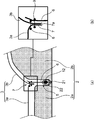
- FIG. 1 is a cross-sectional explanatory view showing a state in which the hanging portion of the epidermis of FIG. 1 is fixed to the pad by the hanging member, and (b) is an enlarged cross-sectional view of the vicinity of the hanging portion of (a).
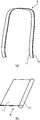
- A) is an overall perspective view of the hanging member of FIG. 1, and (b) is an enlarged view of an end portion of the hanging member of (a).
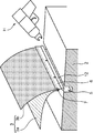
- FIG. 5 is a perspective explanatory view showing a process of fixing a curved portion of a hanging portion and a hanging member corresponding to FIG. 5 to a groove of a pad.
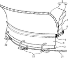
- FIG. 6 is a perspective explanatory view showing a step of fixing the rigid portion of the hanging member of FIG. 6 to a fixing wire such as a wire inside a groove of a pad by using a fastener such as an ohm clip.
- FIG. 8 is a sectional view taken along line IX-IX of FIG.
- FIG. 5 is a cross-sectional explanatory view showing a dimensional relationship in the cross-sectional view of FIG. (A) is a cross-sectional view showing a state in which the hanging portion of the skin of the conventional seat is fixed to the pad by the hanging member as a comparative example, and (b) is an enlarged cross-sectional view of the vicinity of the hanging portion of (a). ..
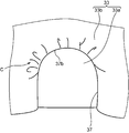
- FIG. 1 it is a perspective view which shows the state which the hanging part of the epidermis in a conventional sheet is fixed to the groove of a bad through a hanging member.
- FIG. 1 it is a figure which shows the state which wrinkles are generated by sewing the hanging member to the curved part of the hanging part in the conventional sheet. It is sectional drawing of the hanging part and the hanging member of FIG. It is a figure which shows the dimensional relationship in the cross-sectional view of FIG.
- the automobile seat 1 according to an embodiment of the seat of the present invention includes a seat back that supports the back of the seated person.
- the seat back includes a pad 2, a skin 3 that covers the surface of the pad 2, and a hanging member 6.
- Pad 2 is a soft member made of foamed resin such as urethane.
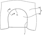
- the pad 2 has a flat surface portion 2a and a curved surface portion 2b.
- the flat surface portion 2a is a portion that supports the back portion of the seat 1 seater.
- the curved surface portion 2b is a portion that rises in a chevron shape that is continuous with each other around the flat surface portion 2a (on the right side in FIG. 2).
- a groove 5 is continuously formed between the flat surface portion 2a and the curved surface portion 2b of the pad 2 as recesses in which the hanging portion 7 of the skin 3 is fixed.
- the skin 3 is a single-layer film-like body made of natural leather, synthetic leather or fabric (cloth products such as woven fabrics), or two or more film-like bodies made of a film such as these leathers and a non-woven fabric or a foamed resin layer. It is a member made of. Specifically, as shown in FIGS. 2A and 2B, the skin 3 covers the surfaces of the flat surface portion 2a and the curved surface portion 2b of the pad 2 without gaps, and the flat surface portion 2a and the curved surface portion 2a and the curved surface portion 2b. It has a plurality of skin portions 3a and 3b having a shape corresponding to the surface shape of 2b.
- the skin 3 is formed by joining the ends of adjacent skin portions 3a and 3b to each other by sewing (see the sewing portion 8 in FIG. 2B) or the like.
- the portions where the ends of the adjacent skin portions 3a and 3b are joined by the sewing portion 8 form the hanging portion 7.
- the skin 3 is fixed to the pad 2 so as to project from the side facing the pad 2 (lower side in FIGS. 2A and 2B) toward the pad 2 and to be drawn into the groove 5. It has a hanging portion 7.
- the hanging portion 7 has a continuous strip-shaped shape as a whole, and has a linear portion (for example, a portion extending in the vertical direction in the range A of FIG. 1) and a curved portion (for example, of FIG. 1) which are continuous with each other. It has two portions) that are curved in a substantially L shape in the range B). Therefore, the overall shape of the hanging portion 7 shown in FIG. 1 is a strip shape bent in an inverted U shape.
- the groove 5 of the pad 2 also has an inverted U shape (that is, a shape having a pair of straight portions and curved portions, respectively) so as to correspond to the overall shape of the hanging portion 7.
- the hanging member 6 has a configuration in which the hanging portion 7 can be fixed to the pad 2 by suspending the hanging portion 7 toward the pad 2.
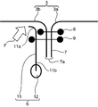
- the hanging member 6 has a strip-shaped main body portion 11 and one edge extending in the longitudinal direction of the main body portion 11 (that is, FIGS. 9 to 9 to 9). It has a linear rigid portion 12 attached along the lower first edge 11b) extending in the longitudinal direction of the 10.
- the rigid portion 12 In the initial state before the hanging member 6 is attached to the hanging portion 7, the rigid portion 12 is more linear than the linear portion as shown in FIG. 3B or the curved portion of the hanging portion 7 (range B in FIG. 1). It has a shape that extends in a gentle curve.
- the bending rigidity of the rigid portion 12 is set higher than the bending rigidity of the main body portion 11.
- the main body portion 11 and the rigid portion 12 may be manufactured of any material as long as these conditions are satisfied. Therefore, for example, the strip-shaped main body portion 11 and the columnar rigid portion 12 may be integrally formed of a synthetic resin or the like. In this case, when considering bending in the direction orthogonal to the longitudinal direction of each of the main body portion 11 and the rigid portion 12 (bending in the vertical direction in FIG. 3B), the columnar rigid portion 12 is a strip-shaped main body portion 11. The moment of inertia of area is larger than that of the above, and the bending rigidity corresponding to the moment of inertia of area is also increased.
- the main body portion 11 may be formed of resin
- the rigid portion 12 may be manufactured of a metal wire or the like and fixed to the first edge 11b of the main body portion 11 by heat welding, adhesion, or the like.
- the hanging portion 7 is formed by sewing two adjacent skin portions 3a and 3b constituting the skin 3.
- the sewn portion 9 in which the main body portion 11 of the hanging member 6 is sewn to the hanging portion 7 is more suspended than the sewn portion 8 in which the two skin portions 3a and 3b of the hanging portion 7 are sewn. It is located on the side (lower side in FIGS. 2 and 9 to 10) close to the edge 7a (FIGS. 4 and 10) extending in the longitudinal direction of the recess 7.
- the upper second edge 11a of the main body 11 of the hanging member 6 is in contact with the surface of the skin 3 facing the pad 2 (specifically,). , It is in contact with the skin portion 3b via the sewn portion 8).
- the second edge 11a, the skin portion 3b, and the sewn portion 8 are shown so as to be separated from each other in order to clearly show these portions, but these portions are actually shown. Are in close contact with each other.
- the hanging portion 7 is fixed to the pad 2 in a state where the main body portion 11 of the hanging member 6 is not folded back and extends along the hanging portion 7.
- a state in which the main body portion 11 is not folded back and extends along the hanging portion 7 means that the portion of the upper second edge 11a of the main body portion 11 does not overlap with the other portion of the main body portion 11. It means a state in which the main body portion 11 extends along the hanging portion 7.
- the ends of the plurality of skin portions 3a and 3b constituting the skin 3 are sewn together like the sewn portion 8.
- the skin 3 is formed with a hanging portion 7 projecting toward the pad 2 (hanging portion forming step).
- the main body portion 11 of the hanging member 6 is sewn to the hanging portion 7 of the skin 3 (sewing process).
- the hanging member 6 a member having a shape in which the main body portion 11 extends linearly with a constant width is used.
- a predetermined distance for example, for example
- the edge 7a extending the rigid portion 12 of the hanging member 6 in the longitudinal direction of the hanging portion 7 is performed.
- the state of being separated from the hanging portion 7 to the outside by the distance D1) between the edge 7a shown in FIGS. 4 and 10 and the lower end 12a (distal end) of the rigid portion 12 is maintained, and FIGS. 9 to 10 show.
- the main body portion 11 is continuously connected to the hanging portion 7 from the straight portion to the curved portion. Sew.
- the rigid portion 12 is maintained in a state of being separated from the end edge 7a extending in the longitudinal direction of the hanging portion 7 to the outside of the hanging portion 7 by a predetermined distance by using a sewing jig. It is preferable that the main body portion 11 of the hanging member 6 is sewn to the hanging portion 7 while holding the rigid portion 12.
- one hanging member 6 is attached to the straight portion (range A and FIG. 5 of FIG. 1) and the curved portion (range B of FIG. 1 and FIGS. 6 to 7) of the hanging portion 7 of the skin 3. It is possible to sew continuously.
- the hanging member 6 after sewing has a shape in an initial state that extends linearly so as to correspond to the shape of the hanging portion 7 (that is, the inverted U shape of the hanging portion 7 in FIG. 1). ) Is transformed into an inverted U shape.
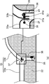
- the hanging portion 7 of the skin 3 is fixed to the groove 5 of the pad 2 via the hanging member 6.
- the skin 3 can be attached to the surface of the pad 2 in a state where the hanging portion 7 is fixed to the pad 2 over its entire length (or a required length) (skin attachment step).
- skin attachment step the production of the sheet 1 is completed.
- the depth of the groove 5 of the pad 2 tends to be shallow, and it is required to narrow the width of the main body 11 of the hanging member 6 corresponding to the depth of the groove 5.
- the hanging member 6 is abutted against the hanging portion 7 of the skin 3 (that is, the rigid portion 12 is previously placed in the hanging portion 7 by a predetermined distance from the edge 7a of the hanging portion 7. Since the main body 11 and the rigid portion 12 are easily visible from the outside because they are sewn apart from the outside of the pad 2, the rigid portion 12 is attached to the fixing wire 21 inside the groove 5 of the pad 2 with the fastener 22. It is possible to easily perform the fixing work.
- the main body 11 of the hanging member 6 has an end at which the rigid portion 12 extends in the longitudinal direction of the hanging portion 7.
- the epidermis 3 It is overlapped with the hanging portion 7.
- the main body portion 11 is continuously sewn to the hanging portion 7 from the straight portion to the curved portion of the hanging portion 7. Then, the hanging portion 7 is fixed to the pad 2 in a state where the main body portion 11 of the hanging member 6 is extended along the hanging portion 7 without being folded back.
- the rigid portion 12 having high bending rigidity in the hanging member 6 is bent and the hanging portion 7 extends from the edge 7a extending in the longitudinal direction of the hanging portion 7.
- the main body portion 11 of the hanging member 6 is continuously sewn to the hanging portion 7 from the straight portion to the curved portion while maintaining a state of extending parallel to the edge 7a at a position separated from the outside. As a result, a restoring force is generated in the rigid portion 12 at the curved portion of the hanging portion 7.
- the portion of the second edge 11a on the upper side of the main body portion 11 of the hanging portion 7 is maintained while the rigid portion 12 is maintained in a state of matching the peripheral length of the end edge 7a of the hanging portion 7.
- the skin 3 is pushed up in the direction away from the pad 2 (see the force F that pushes up the skin 3 in FIG. 9).
- the skin 3 has a three-dimensional shape protruding outward at the curved portion of the hanging portion 7, and it is possible to prevent the occurrence of wrinkles on the skin 3.
- the hanging member 6 has a configuration in which the rigid portion 12 is attached to the lower first edge 11b extending in the longitudinal direction of the main body portion 11 ( (See FIGS. 9 to 10), the main body 11 is continuously sewn to the hanging portion 7 from the straight portion (range A in FIG. 1) to the curved portion (range B in FIG. 1) of the hanging portion 7 of the skin 3.
- the hanging portion 7 of the skin 3 rises with respect to the main body portion of the skin 3 (specifically, the skin portion 3b located outside the curved portion), and the second upper side of the main body portion 11 of the hanging member 6 is raised.
- the rigid portion 12 is attached to the lower first edge 11b of the main body portion 11 of the hanging member 6, and the rigid portion 12 extends parallel to the end edge 7a of the hanging portion 7 of the skin 3.
- the main body portion 11 of the hanging member 6 is along the edge 7a at a position where the rigid portion 12 is separated from the edge 7a extending in the longitudinal direction of the hanging portion 7 to the outside of the hanging portion 7.
- the epidermis is in a state where the portion of the upper second edge 11a of the main body 11 (that is, the edge opposite to the lower first edge 11b to which the rigid portion 12 is attached) is overlapped with the epidermis 3. It is overlapped with the hanging portion 7 of 3. In this configuration, since the hanging member 6 is not folded back, the manufacturing tolerance and the dimensional variation are reduced.
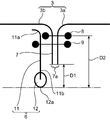
- the main body of the hanging member 6 has a positional relationship in which the rigid portion 12 extends in parallel at a position separated from the edge 7a of the hanging portion 7 by a predetermined distance D1 to the outside of the hanging portion 7.
- the portion 11 is continuously sewn to the hanging portion 7 from the straight portion to the curved portion. Therefore, the distance D2 (that is, the distance from the sewn portion 8 between the epidermis portions 3a and 3b of the epidermis 3 to the lower end (distal end) 12a of the rigid portion 12), which is a reference of the manufacturing tolerance, is the tolerance of the distance D1.
- the distance D1 is strictly controlled during the sewing process, it is possible to reduce the manufacturing tolerance of the reference distance D2.
- the conventional processing for example, attaching another part only to the curved portion
- the conventional processing is not performed. It is possible to continuously sew one hanging member 6 to the hanging portion 7 of the skin 3, and the workability of the sewing work is improved.
- the rigid portion 12 of the hanging member 6 faces the fixing direction (downward in FIGS. 9 to 10) of the hanging portion 7 of the skin 3, the trouble of folding back the main body portion 11 of the hanging member 6 can be saved. Workability is improved.
- the positions of these sewn portions are different, so that the possibility of spoiling the appearance of the sheet 1 is suppressed. That is, when the positions of the sewn portions 8 and 9 are on the same line, the appearance of the sheet 1 may be spoiled.
- the skin 3 is leather
- the needle hole at the time of sewing is the hanging portion 7.
- the weaving thread is cut when the needle penetrates the hanging portion 7 on the same line at the time of sewing, and the cut weaving thread is cut.
- the upper second edge 11a of the main body 11 of the hanging member 6 is the surface of the skin 3 facing the pad 2. Is in contact with.
- the main body portion 11 of the hanging member 6 can surely exert the effect of pushing the skin 3 outward, and the occurrence of wrinkles of the skin 3 in the curved portion of the hanging portion 7 can be surely prevented. Is possible.
- FIGS. 9 to 10 show a state in which the skin is in contact with the skin portion 3b via the sewn portion 8, the skin portion 3b may be in direct contact with the skin portion 3b.
- the rigid portion 12 of the hanging member 6 is set at a predetermined distance from the edge 7a extending in the longitudinal direction of the hanging portion 7. While maintaining the state of being separated from the outside of the hanging portion 7 and superimposing the portion of the upper second edge 11a of the main body portion 11 of the hanging member 6 on the skin 3, the main body portion 11 is stretched from the straight portion to the curved portion.
- the hanging portion 7 is fixed to the pad 2 in a state where the main body portion 11 of the hanging member 6 is extended along the hanging portion 7 without being folded back. By doing so, it is characterized by including a skin attachment step of attaching the epidermis 3 to the pad 2.
- the rigid portion 12 of the hanging member 6 is maintained in a state of being separated from the edge 7a extending in the longitudinal direction of the hanging portion 7 of the skin 3 to the outside of the hanging portion 7 by a predetermined distance, and is suspended.
- the rigid portion 12 is suspended while being kept parallel to the end edge 7a extending in the longitudinal direction of the suspension 7.
- the main body portion 11 of the member 6 can be continuously sewn to the hanging portion 7 from the straight portion to the curved portion.
- the main body portion 11 of the hanging member 6 can be continuously sewn to the hanging portion 7 from the straight portion to the curved portion while deforming the rigid portion 12 following the curved portion of the hanging portion 7.
- the rigid portion 12 of the hanging member 6 is predetermined from the edge 7a extending in the longitudinal direction of the hanging portion 7. Since the state of being separated from the outside of the hanging member 7 by a distance is maintained and the portion of the second edge 11a of the main body 11 of the hanging member 6 is overlapped with the skin 3, there is no need to fold back the hanging member 6. , Manufacturing tolerances and dimensional variations are reduced. Therefore, in order to attach the hanging member 6 to the curved portion of the hanging portion 7, one hanging member 6 is continuously sewn to the hanging portion 7 of the skin 3 without performing the conventional treatment. It is possible to improve the workability of sewing work.
- the rigid portion 12 of the hanging member 6 is positioned so as to face the fixing direction (downward in FIGS. 9 to 10) of the hanging portion 7 of the skin 3, the trouble of folding back the main body portion 11 of the hanging member 6 can be saved. , Assembling workability is improved.
- the rigid portion 12 of the hanging member 6 is maintained in a state of being separated from the edge 7a extending in the longitudinal direction of the hanging portion 7 to the outside of the hanging portion 7 by a predetermined distance and suspended.
- the hanging portion 7 is formed by continuously sewing the main body 11 from the straight portion to the curved portion while overlapping the portion of the second edge 11a of the main body portion 11 of the fitting member 6 on the skin 3.
- the restoring force generated in the rigid portion 12 keeps the rigid portion 12 in the same state as the circumferential length of the edge 7a of the hanging portion 7, and the second upper side of the main body portion 11 of the hanging portion 7.
- the skin 3 is pushed up in the direction away from the pad 2 through the portion of the edge 11a (see the force F pushing up the skin 3 in FIG. 9).
- the skin 3 has a three-dimensional shape protruding outward at the curved portion 7b of the hanging portion 7, and it is possible to prevent the occurrence of wrinkles on the skin 3.
- the rigid portion 12 attached to the first edge 11b extending in the longitudinal direction of the main body portion 11 of the hanging member 6 is placed outside the hanging portion 7 by a predetermined distance from the end edge 7a of the hanging portion 7 of the skin 3. By separating them, the hanging member 6 can be accurately positioned with respect to the hanging portion 7.
- the main body portion 11 of the hanging member 6 is positioned so as to be sewn to the hanging portion 7 with a constant width regardless of the width of the hanging portion 7 of the skin 3. Therefore, since it is not necessary to change the width of the main body portion 11 of the hanging member 6 according to the width of the hanging portion 7 of the skin 3, the width of the main body portion 11 should be unified and the hanging member 6 should be shared. Is possible. This makes it possible to reduce the manufacturing cost.
- the hanging member 6 of the present embodiment has a width of the main body 11 as compared with a conventional hanging member (for example, a hanging member 36 used by folding back the main body 41 shown in FIGS. 11 to 15). It is possible to make it narrower, and it is possible to reduce the manufacturing cost in this respect as well.
- a conventional hanging member for example, a hanging member 36 used by folding back the main body 41 shown in FIGS. 11 to 15. It is possible to make it narrower, and it is possible to reduce the manufacturing cost in this respect as well.
- the hanging member 6 has a shape in which the main body 11 extends linearly with a constant width. As a result, it is not necessary to process the hanging member 6 into a shape along the curved portion of the hanging portion 7 before sewing it to the hanging portion 7, and the manufacturing cost can be suppressed.
- the rigid portion 12 of the hanging member 6 is held in a state of being separated from the end edge 7a of the hanging member 6 by a predetermined distance to the outside of the hanging portion 7 by using a sewing jig. Therefore, it is not necessary to provide a mark for positioning the hanging member 6 on either the hanging member 6 or the hanging portion 7, and the manufacturing cost can be reduced.
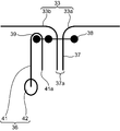
- the structure of the conventional seat as a comparative example shown in FIGS. 11 to 15 has a pad 32 having a groove 35, a skin 33 having a hanging portion 37, a hanging member 36, and a hanging member 36.
- the edge 41a (the edge opposite to the rigid portion 42) extending in the longitudinal direction of the main body portion 41 of the hanging member 36 coincides with the end edge 37a of the hanging portion 37.
- the edge 7a (FIGS. 4 and 10) of the hanging portion 7 and the rigid portion 12 are positioned so as to be separated from each other by a predetermined distance D1 to the outside of the hanging portion 7. It differs in that it is matched.
- the main body 41 of the hanging member 36 is sewn to the hanging portion 37 and then folded back at the position of the sewn portion 39 so that the rigid portion 42 is the groove 35 of the pad 32.
- the main body portion 11 of the hanging member 6 is not folded back after being sewn to the hanging portion 7, and the main body portion 11 Is different in that the rigid portion 12 is fixed inside the groove 5 of the pad 2 in a state of extending parallel to the hanging portion 7.
- the bending member 6 is bent. Suspended while maintaining a state in which the highly rigid rigid portion 12 is bent and extends parallel to the end edge 7a at a position separated from the edge 7a extending in the longitudinal direction of the hanging portion 7 to the outside of the hanging portion 7. Since the main body portion 11 of the pulling member 6 is continuously sewn to the hanging portion 7 from the straight portion to the curved portion, a restoring force is generated in the rigid portion 12 in the curved portion of the hanging portion 7.
- the rigid portion 12 Due to the restoring force of the rigid portion 12, the rigid portion 12 is maintained in a state of matching the peripheral length of the end edge 7a of the hanging portion 7 through the portion of the second edge 11a of the main body portion 11 of the hanging portion 7.
- the skin 3 is pushed up in the direction away from the pad 2 (see the force F that pushes up the skin 3 in FIG. 9).
- the skin 3 has a three-dimensional shape protruding outward at the curved portion 7b of the hanging portion 7, and it is possible to prevent the occurrence of wrinkles on the skin 3.
- the main body portion 11 of the hanging member 6 has an edge 7a in which the rigid portion 12 extends in the longitudinal direction of the hanging portion 7.
- the second edge 11a of the main body 11 (that is, the side opposite to the first edge 11b to which the rigid portion 12 is attached) extends parallel to the edge 7a at a position separated from the hanging portion 7 to the outside. Since the portion of the edge) is overlapped with the hanging portion 7 of the skin 3 in a state of being overlapped with the skin 3, the hanging member 6 is not folded back, so that the manufacturing tolerance and the dimensional variation are reduced.
- the manufacturing tolerance and the dimensional variation become large.
- the distance D3 which is a reference of the manufacturing tolerance in the comparative example shown in FIG. 15 (that is, the distance from the sewn portion 38 between the epidermis portions 33a and 33b of the epidermis 33 to the lower end (distal end) 42a of the rigid portion 42. )
- the manufacturing tolerance of the reference distance D3 Depends on the total length of the folded main body 41, so that it is difficult to reduce the manufacturing tolerance of the reference distance D3, and the manufacturing tolerance and the dimensional variation become large.
- the work of folding back the hanging member 36 is required, which takes time and effort, and the hanging member 36 cannot be accurately positioned, so that the manufacturing tolerance and the dimensional variation become large.
- one hanging member 36 cannot be continuously sewn to the hanging portion 37 of the skin 33, and a separate part is required at the curved portion of the hanging portion 37, so that the workability of the sewing work is easy. Is difficult to improve.
- the main body portion of the main body portion extends in parallel along the edge at a position where the rigid portion extends in the longitudinal direction of the hanging portion and is separated from the outside of the hanging portion, and the second main body portion of the main body portion.
- the edge portion overlaps the skin, it is overlapped with the hanging portion of the skin, and the main body portion is continuously sewn to the hanging portion from the straight portion to the curved portion, and the suspension is provided.
- the recessed portion is characterized in that the main body portion of the hanging member is fixed to the pad in a state of extending along the hanging portion without being folded back.
- the main body portion of the hanging member extends in parallel along the end edge at a position where the rigid portion extends in the longitudinal direction of the hanging portion and is separated from the outside of the hanging portion, and the main body portion of the main body portion.
- the second edge portion is overlapped with the hanging portion of the epidermis in a state of being overlapped with the epidermis.
- the main body portion is continuously sewn to the hanging portion from the straight portion to the curved portion.
- the hanging portion is fixed to the pad in a state in which the main body portion of the hanging member is not folded back and extends along the hanging portion.
- the rigid portion having high bending rigidity in the hanging member is bent at a position separated from the edge extending in the longitudinal direction of the hanging portion to the outside of the hanging portion.
- the main body of the hanging member is continuously sewn to the hanging portion from the straight portion to the curved portion while maintaining a state of extending parallel to the edge.
- a restoring force is generated in the rigid portion in the curved portion of the hanging portion. Due to the restoring force of this rigid portion, the direction in which the rigid portion is separated from the pad via the second edge portion of the main body portion of the suspension portion while maintaining a state in which the rigid portion matches the peripheral length of the edge of the suspension portion. Push up to.
- the epidermis has a three-dimensional shape that projects outward at the curved portion of the hanging portion, and it is possible to prevent the occurrence of wrinkles on the epidermis.
- the hanging portion is formed by sewing two adjacent skin portions constituting the skin, and the portion where the main body portion is sewn to the hanging portion is the hanging portion. It is preferable that the two skin portions of the recessing portion are located closer to the edge extending in the longitudinal direction of the hanging portion than the portion to be sewn.
- the sheet manufacturing method of the present embodiment includes a pad, a skin covering the surface of the pad, and a skin having a hanging portion protruding from the side facing the pad in a direction approaching the pad, and the hanging.
- the hanging member includes a hanging member for fixing the portion toward the pad, the hanging portion has a linear portion and a curved portion continuous with each other, and the hanging member has a first edge extending in the longitudinal direction and a curved portion. It has a strip-shaped main body portion having a second edge, and a linear rigid portion having a bending rigidity higher than that of the main body portion and attached along the first edge of the main body portion.
- a method for manufacturing a sheet, in which the rigid portion is maintained in a state of being separated from the end edge extending in the longitudinal direction of the hanging portion by a predetermined distance to the outside of the hanging portion, and the second edge of the main body portion is used.
- a sewing step in which the main body portion is continuously sewn to the hanging portion from the straight portion to the curved portion while the portion is overlapped with the skin, and the main body portion of the hanging member is not folded back. It is characterized by including a skin skin attaching step of attaching the skin to the pad by fixing the hanging part to the pad in a state of extending along the hanging part.
- the rigid portion of the hanging member is maintained in a state of being separated from the edge extending in the longitudinal direction of the hanging portion of the epidermis to the outside of the hanging portion by a predetermined distance, and the main body portion of the hanging member is described.
- the main body portion of the suspension member is continuously extended from the straight portion to the curved portion while maintaining the rigid portion parallel to the end edge extending in the longitudinal direction of the suspension portion. It is possible to sew on the hanging part.
- the main body portion of the hanging member can be continuously sewn to the hanging portion from the straight portion to the curved portion while the rigid portion is deformed following the curved portion of the hanging portion.
- the hanging member having a shape in which the main body portion extends linearly with a constant width.
- the rigid portion in the sewing step, is separated from the edge extending in the longitudinal direction of the hanging portion by a predetermined distance to the outside of the hanging portion by using a sewing jig. It is preferable to sew the main body portion of the hanging member to the hanging portion while holding the rigid portion so as to maintain the state.
- the rigid portion of the hanging member is held in a state of being separated from the edge of the hanging member by a predetermined distance to the outside of the hanging portion by using a sewing jig, so that the hanging member is suspended. It is not necessary to provide a mark for positioning the hanging member on either the member or the hanging portion, and the manufacturing cost can be reduced.
Landscapes
- Engineering & Computer Science (AREA)
- Mechanical Engineering (AREA)
- Aviation & Aerospace Engineering (AREA)
- Transportation (AREA)
- Textile Engineering (AREA)
- Manufacturing & Machinery (AREA)
- Seats For Vehicles (AREA)
Abstract
Description
パッドに対向する側から当該パッドに近づく方向に突出する吊込み部を有する表皮と、前記吊込み部を前記パッドに向けて固定する吊込み部材とを備え、前記吊込み部は、互いに連続する直線部分および曲線部分を有しており、前記吊込み部材は、長手方向に延びる第1縁および第2縁を有する帯状の本体部と、前記本体部よりも高い曲げ剛性を有し、かつ、前記本体部の前記第1縁に沿って取り付けられた線状の剛性部とを有しているシートの製造方法であって、前記剛性部を前記吊込み部の長手方向に延びる端縁から所定距離だけ当該吊込み部の外側に離間した状態を維持するとともに前記本体部の前記第2縁の部分を前記表皮に重ねながら、前記本体部を前記直線部分から前記曲線部分にかけて連続的に前記吊込み部に縫着する縫着工程と、前記吊込み部材の前記本体部が折り返されないで前記吊込み部に沿って延びた状態で、前記吊込み部を前記パッドに固定することにより、前記表皮を前記パッドに取り付ける表皮取付け工程とを含むことを特徴とする。
上記のように構成されたシート1は、以下のようにして製造される。
(1)本実施形態のシート1では、図2(a)、(b)に示されるように、吊込み部材6の本体部11は、剛性部12が吊込み部7の長手方向に延びる端縁7aから当該吊込み部7の外側に離間した位置で当該端縁7aに沿って平行に延びかつ本体部11の上側の第2縁11aの部分が表皮3に重なった状態で、表皮3の吊込み部7に重ね合わされている。しかも、本体部11は、吊込み部7の直線部分から曲線部分にかけて連続的に吊込み部7に縫着されている。そして、吊込み部7は、吊込み部材6の本体部11が折り返されないで吊込み部7に沿って延びた状態で、パッド2に固定されている。
以下、上記の本実施形態のシート1の構成との比較例として、従来のシートの構造について図11~15を参照しながら、本実施形態と比較例との対比説明をする。
前記実施形態をまとめると以下のとおりである。
Claims (6)
- パッドと、
前記パッドの表面を覆う表皮であって、前記パッドに対向する側から当該パッドに近づく方向に突出する吊込み部を有する表皮と、
前記吊込み部を前記パッドに固定する吊込み部材とを備え、
前記吊込み部は、互いに連続する直線部分および曲線部分を有しており、
前記吊込み部材は、長手方向に延びる第1縁および第2縁を有する帯状の本体部と、前記本体部よりも高い曲げ剛性を有し、かつ、前記本体部の前記第1縁に沿って取り付けられた線状の剛性部とを有しており、
前記吊込み部材の前記本体部は、前記剛性部が前記吊込み部の長手方向に延びる端縁から当該吊込み部の外側に離間した位置で当該端縁に沿って平行に延びかつ前記本体部の前記第2縁の部分が前記表皮に重なった状態で、前記表皮の前記吊込み部に重ね合わされ、
前記本体部は、前記直線部分から前記曲線部分にかけて連続的に前記吊込み部に縫着され、
前記吊込み部は、前記吊込み部材の前記本体部が折り返されないで前記吊込み部に沿って延びた状態で、前記パッドに固定されている、
シート。 - 前記吊込み部は、前記表皮を構成する隣接する2枚の表皮部分が縫着することによって形成され、
前記本体部が前記吊込み部に縫着される部分は、前記吊込み部における前記2枚の表皮部分が縫着される部分よりも当該吊込み部の長手方向に延びる端縁に近い側に位置している
請求項1に記載のシート。 - 前記吊込み部材の前記本体部における前記第2縁の部分が前記表皮における前記パッドに対向する側の面に当接している、
請求項1または2に記載のシート。 - パッドと、前記パッドの表面を覆う表皮であって、前記パッドに対向する側から当該パッドに近づく方向に突出する吊込み部を有する表皮と、前記吊込み部を前記パッドに固定する吊込み部材とを備え、前記吊込み部は、互いに連続する直線部分および曲線部分を有しており、前記吊込み部材は、長手方向に延びる第1縁および第2縁を有する帯状の本体部と、前記本体部よりも高い曲げ剛性を有し、かつ、前記本体部の前記第1縁に沿って取り付けられた線状の剛性部とを有しているシートの製造方法であって、
前記剛性部を前記吊込み部の長手方向に延びる端縁から所定距離だけ当該吊込み部の外側に離間した状態を維持するとともに前記本体部の前記第2縁の部分を前記表皮に重ねながら、前記本体部を前記直線部分から前記曲線部分にかけて連続的に前記吊込み部に縫着する縫着工程と、
前記吊込み部材の前記本体部が折り返されないで前記吊込み部に沿って延びた状態で、前記吊込み部を前記パッドに固定することにより、前記表皮を前記パッドに取り付ける表皮取付け工程と、
を含むシートの製造方法。 - 前記吊込み部材として、前記本体部が一定の幅で直線的に延びる形状を有するものを使用する、
請求項4に記載のシートの製造方法。 - 前記縫着工程において、縫着治具を用いて、前記剛性部を前記吊込み部の長手方向に延びる端縁から所定距離だけ当該吊込み部の外側に離間した状態を維持するように、前記剛性部を保持しながら前記吊込み部材の前記本体部を前記吊込み部に縫着する、
請求項4または5に記載のシートの製造方法。
Priority Applications (3)
| Application Number | Priority Date | Filing Date | Title |
|---|---|---|---|
| US17/754,835 US12319179B2 (en) | 2019-11-06 | 2020-09-17 | Seat and seat production method |
| CN202080071293.6A CN114599550B (zh) | 2019-11-06 | 2020-09-17 | 座椅以及座椅的制造方法 |
| EP20884649.3A EP4026458B1 (en) | 2019-11-06 | 2020-09-17 | Seat and seat production method |
Applications Claiming Priority (2)
| Application Number | Priority Date | Filing Date | Title |
|---|---|---|---|
| JP2019-201681 | 2019-11-06 | ||
| JP2019201681A JP7391359B2 (ja) | 2019-11-06 | 2019-11-06 | シート |
Publications (1)
| Publication Number | Publication Date |
|---|---|
| WO2021090588A1 true WO2021090588A1 (ja) | 2021-05-14 |
Family
ID=75849896
Family Applications (1)
| Application Number | Title | Priority Date | Filing Date |
|---|---|---|---|
| PCT/JP2020/035344 Ceased WO2021090588A1 (ja) | 2019-11-06 | 2020-09-17 | シート、およびシートの製造方法 |
Country Status (5)
| Country | Link |
|---|---|
| US (1) | US12319179B2 (ja) |
| EP (1) | EP4026458B1 (ja) |
| JP (1) | JP7391359B2 (ja) |
| CN (1) | CN114599550B (ja) |
| WO (1) | WO2021090588A1 (ja) |
Families Citing this family (5)
| Publication number | Priority date | Publication date | Assignee | Title |
|---|---|---|---|---|
| JP7394010B2 (ja) * | 2020-04-17 | 2023-12-07 | 株式会社タチエス | 乗り物用シート及びトリムカバーの製造方法 |
| US12326742B2 (en) | 2022-12-22 | 2025-06-10 | Lear Corporation | Valve and actuator assembly for a fluid system in a vehicle seat assembly |
| DK181559B1 (en) * | 2022-06-28 | 2024-05-15 | Lear Corp | METHOD AND MACHINE FOR ATTACHING A SEAT COVER TO WELDED POLYMER FIBERS WITH A SPIRAL WRAPPED ADJUSTMENT ATTACHMENT CONNECTOR AND APPARATUS |
| US12337738B2 (en) | 2022-11-09 | 2025-06-24 | Lear Corporation | Fluid system for a vehicle seat assembly |
| JP2025157815A (ja) * | 2024-04-03 | 2025-10-16 | トヨタ紡織株式会社 | 乗物用シート |
Citations (4)
| Publication number | Priority date | Publication date | Assignee | Title |
|---|---|---|---|---|
| JPH0645600U (ja) * | 1992-11-30 | 1994-06-21 | 株式会社タチエス | 車両用シートにおけるトリムカバーの係止体構造 |
| JP2007275557A (ja) * | 2006-03-13 | 2007-10-25 | Ykk Corp | クリップ部材及びクッション部材の表皮材吊込構造 |
| JP2009148350A (ja) * | 2007-12-19 | 2009-07-09 | Toyota Boshoku Corp | 吊り込み部品 |
| JP2018126435A (ja) | 2017-02-10 | 2018-08-16 | トヨタ紡織株式会社 | 乗物用シート及びその製造方法 |
Family Cites Families (10)
| Publication number | Priority date | Publication date | Assignee | Title |
|---|---|---|---|---|
| US3632164A (en) * | 1970-04-02 | 1972-01-04 | Universal Oil Prod Co | Vehicle seat having an improved seat cover attachment system |
| US3794378A (en) * | 1972-11-24 | 1974-02-26 | Ford Motor Co | Seat assembly |
| DE20100848U1 (de) | 2001-01-16 | 2001-03-15 | Gabriel, Christian, 84030 Ergolding | Clipelement zum Verbinden eines Polsterbezuges mit einem Schaumpolsterelement und Befestigungsvorrichtung |
| US6899399B2 (en) * | 2003-07-08 | 2005-05-31 | Lear Corporation | Attachment assembly for securing trim material to the padding of a vehicle seat |
| US6964453B1 (en) * | 2004-06-02 | 2005-11-15 | Irvin Automotive Products, Inc. | Seat trim cover assembly aid |
| DE102005012320A1 (de) * | 2005-03-17 | 2006-09-21 | Faurecia Autositze Gmbh & Co. Kg | Kraftfahrzeugsitz |
| JP5767994B2 (ja) | 2012-03-26 | 2015-08-26 | 日本発條株式会社 | 車両用シート |
| CN110053525B (zh) | 2014-10-17 | 2021-09-28 | 提爱思科技股份有限公司 | 车用座椅 |
| JP6612777B2 (ja) | 2014-12-16 | 2019-11-27 | デルタ工業株式会社 | シート |
| WO2017051466A1 (ja) | 2015-09-25 | 2017-03-30 | ジョンソン コントロールズ テクノロジー カンパニ- | バックボード取り付け構造及び乗り物用シート |
-
2019
- 2019-11-06 JP JP2019201681A patent/JP7391359B2/ja active Active
-
2020
- 2020-09-17 EP EP20884649.3A patent/EP4026458B1/en active Active
- 2020-09-17 CN CN202080071293.6A patent/CN114599550B/zh active Active
- 2020-09-17 US US17/754,835 patent/US12319179B2/en active Active
- 2020-09-17 WO PCT/JP2020/035344 patent/WO2021090588A1/ja not_active Ceased
Patent Citations (4)
| Publication number | Priority date | Publication date | Assignee | Title |
|---|---|---|---|---|
| JPH0645600U (ja) * | 1992-11-30 | 1994-06-21 | 株式会社タチエス | 車両用シートにおけるトリムカバーの係止体構造 |
| JP2007275557A (ja) * | 2006-03-13 | 2007-10-25 | Ykk Corp | クリップ部材及びクッション部材の表皮材吊込構造 |
| JP2009148350A (ja) * | 2007-12-19 | 2009-07-09 | Toyota Boshoku Corp | 吊り込み部品 |
| JP2018126435A (ja) | 2017-02-10 | 2018-08-16 | トヨタ紡織株式会社 | 乗物用シート及びその製造方法 |
Non-Patent Citations (1)
| Title |
|---|
| See also references of EP4026458A4 |
Also Published As
| Publication number | Publication date |
|---|---|
| EP4026458B1 (en) | 2026-03-18 |
| EP4026458A1 (en) | 2022-07-13 |
| JP7391359B2 (ja) | 2023-12-05 |
| CN114599550B (zh) | 2025-01-10 |
| CN114599550A (zh) | 2022-06-07 |
| US20240227645A1 (en) | 2024-07-11 |
| EP4026458A4 (en) | 2022-10-19 |
| US12319179B2 (en) | 2025-06-03 |
| JP2021074092A (ja) | 2021-05-20 |
Similar Documents
| Publication | Publication Date | Title |
|---|---|---|
| WO2021090588A1 (ja) | シート、およびシートの製造方法 | |
| EP2777438A1 (en) | Cover-material fastening cord | |
| CN102655777B (zh) | 拉链牙链带的缝制方法及拉链被覆制品的制造方法、以及拉链被覆制品及缝纫机压脚 | |
| CN107685662B (zh) | 装饰罩以及座椅部件 | |
| WO2014118949A1 (ja) | スライドファスナー付き物品及びスライドファスナー付き物品の製造方法、並びに、ファスナーストリンガー及びスライドファスナー | |
| WO2020255705A1 (ja) | シート | |
| JP6704707B2 (ja) | 車両用シートのトリムカバーの縫製処理方法、及びそれを用いた車両用シート | |
| US9861167B2 (en) | Ornament holder | |
| US10711379B2 (en) | Embroidery workpiece holding device | |
| JP5501255B2 (ja) | 隠しスライドファスナー用のファスナーエレメントと同ファスナーエレメントを用いた隠しスライドファスナー | |
| JP7191490B2 (ja) | シート止着具 | |
| JP2010063743A (ja) | シートカバーの締結構造 | |
| JP5642491B2 (ja) | 自動車シートに用いるトリム・カバー・アッセンブリの縫合せ方法およびトリム・カバー・アッセンブリ | |
| JP2010052537A (ja) | 表皮材、および内装品 | |
| JP2016215983A (ja) | 乗物用シート | |
| JP7212498B2 (ja) | 縫製品および縫製品の製造方法 | |
| JP2011115443A (ja) | 車両用シート | |
| JPS61252305A (ja) | トリミングを取付けた皮革または編織物品およびその取付け法 | |
| CN114474879A (zh) | 表皮部件 | |
| JP7832083B2 (ja) | 表皮部材及び内装部材 | |
| JP4556487B2 (ja) | 表皮端部の接合構造 | |
| TWI748185B (zh) | 帶狀體或繩狀體之夾扣構造及衣服 | |
| JP7394010B2 (ja) | 乗り物用シート及びトリムカバーの製造方法 | |
| JP3702020B2 (ja) | 面状ファスナを用いたシートの吊り込み方法 | |
| JP2003325293A (ja) | 布団カバー |
Legal Events
| Date | Code | Title | Description |
|---|---|---|---|
| 121 | Ep: the epo has been informed by wipo that ep was designated in this application |
Ref document number: 20884649 Country of ref document: EP Kind code of ref document: A1 |
|
| ENP | Entry into the national phase |
Ref document number: 2020884649 Country of ref document: EP Effective date: 20220405 |
|
| WWE | Wipo information: entry into national phase |
Ref document number: 17754835 Country of ref document: US |
|
| NENP | Non-entry into the national phase |
Ref country code: DE |
|
| WWG | Wipo information: grant in national office |
Ref document number: 202080071293.6 Country of ref document: CN |
|
| WWG | Wipo information: grant in national office |
Ref document number: 17754835 Country of ref document: US |
|
| WWG | Wipo information: grant in national office |
Ref document number: 2020884649 Country of ref document: EP |