WO2021090884A1 - Machine électrique rotative - Google Patents
Machine électrique rotative Download PDFInfo
- Publication number
- WO2021090884A1 WO2021090884A1 PCT/JP2020/041362 JP2020041362W WO2021090884A1 WO 2021090884 A1 WO2021090884 A1 WO 2021090884A1 JP 2020041362 W JP2020041362 W JP 2020041362W WO 2021090884 A1 WO2021090884 A1 WO 2021090884A1
- Authority
- WO
- WIPO (PCT)
- Prior art keywords
- magnet
- conductor
- winding
- phase
- circumferential direction
- Prior art date
- Legal status (The legal status is an assumption and is not a legal conclusion. Google has not performed a legal analysis and makes no representation as to the accuracy of the status listed.)
- Ceased
Links
Images


Classifications
-
- H—ELECTRICITY
- H02—GENERATION; CONVERSION OR DISTRIBUTION OF ELECTRIC POWER
- H02K—DYNAMO-ELECTRIC MACHINES
- H02K21/00—Synchronous motors having permanent magnets; Synchronous generators having permanent magnets
- H02K21/26—Synchronous motors having permanent magnets; Synchronous generators having permanent magnets with rotating armatures and stationary magnets
- H02K21/28—Synchronous motors having permanent magnets; Synchronous generators having permanent magnets with rotating armatures and stationary magnets with armatures rotating within the magnets
- H02K21/30—Synchronous motors having permanent magnets; Synchronous generators having permanent magnets with rotating armatures and stationary magnets with armatures rotating within the magnets having annular armature cores with salient poles
-
- H—ELECTRICITY
- H02—GENERATION; CONVERSION OR DISTRIBUTION OF ELECTRIC POWER
- H02K—DYNAMO-ELECTRIC MACHINES
- H02K1/00—Details of the magnetic circuit
- H02K1/06—Details of the magnetic circuit characterised by the shape, form or construction
- H02K1/22—Rotating parts of the magnetic circuit
- H02K1/27—Rotor cores with permanent magnets
- H02K1/2786—Outer rotors
- H02K1/2787—Outer rotors the magnetisation axis of the magnets being perpendicular to the rotor axis
- H02K1/2789—Outer rotors the magnetisation axis of the magnets being perpendicular to the rotor axis the rotor consisting of two or more circumferentially positioned magnets
- H02K1/2791—Surface mounted magnets; Inset magnets
- H02K1/2792—Surface mounted magnets; Inset magnets with magnets arranged in Halbach arrays
-
- H—ELECTRICITY
- H02—GENERATION; CONVERSION OR DISTRIBUTION OF ELECTRIC POWER
- H02K—DYNAMO-ELECTRIC MACHINES
- H02K1/00—Details of the magnetic circuit
- H02K1/02—Details of the magnetic circuit characterised by the magnetic material
-
- H—ELECTRICITY
- H02—GENERATION; CONVERSION OR DISTRIBUTION OF ELECTRIC POWER
- H02K—DYNAMO-ELECTRIC MACHINES
- H02K3/00—Details of windings
- H02K3/04—Windings characterised by the conductor shape, form or construction, e.g. with bar conductors
-
- H—ELECTRICITY
- H02—GENERATION; CONVERSION OR DISTRIBUTION OF ELECTRIC POWER
- H02K—DYNAMO-ELECTRIC MACHINES
- H02K3/00—Details of windings
- H02K3/46—Fastening of windings on the stator or rotor structure
- H02K3/47—Air-gap windings, i.e. iron-free windings
-
- H—ELECTRICITY
- H02—GENERATION; CONVERSION OR DISTRIBUTION OF ELECTRIC POWER
- H02K—DYNAMO-ELECTRIC MACHINES
- H02K2203/00—Specific aspects not provided for in the other groups of this subclass relating to the windings
- H02K2203/09—Machines characterised by wiring elements other than wires, e.g. bus rings, for connecting the winding terminations
-
- H—ELECTRICITY
- H02—GENERATION; CONVERSION OR DISTRIBUTION OF ELECTRIC POWER
- H02K—DYNAMO-ELECTRIC MACHINES
- H02K5/00—Casings; Enclosures; Supports
- H02K5/04—Casings or enclosures characterised by the shape, form or construction thereof
- H02K5/22—Auxiliary parts of casings not covered by groups H02K5/06-H02K5/20, e.g. shaped to form connection boxes or terminal boxes
- H02K5/225—Terminal boxes or connection arrangements
Definitions
- This disclosure relates to rotary electric machines.
- Patent Document 1 a rotary electric machine including a field magnet including a magnet portion having a plurality of magnetic poles having alternating polarities in the circumferential direction and an armature having a multi-phase armature winding. It has been known.
- the armature windings of each phase have conducting wires extending in the axial direction and arranged side by side in the circumferential direction.
- a conductor-to-conductor member is provided between each conductor in the circumferential direction, and as the conductor-to-conductor member, the width dimension of the conductor-to-conductor member in one magnetic pole in the circumferential direction is Wt, and the saturation magnetic flux density of the conductor-to-conductor member is Bs.
- Wt the width dimension of the magnet part in one magnetic pole in the circumferential direction
- Bs the saturation magnetic flux density of the conductor-to-conductor member
- a rotary electric machine having a structure (hereinafter referred to as a slotless structure) in which a member between conductors is not provided between each conductor portion in the circumferential direction.
- the armature does not have a portion that functions as a tooth for guiding the magnetic flux of the magnet portion of the magnet portion. For this reason, there is a concern that the amount of magnet magnetic flux interlinking with the conducting wire portion constituting the armature winding will decrease, and the torque of the rotating electric machine will decrease.
- the main purpose of this disclosure is to provide a rotary electric machine capable of increasing torque.
- the means 1 includes a field magnet including a magnet portion having a plurality of magnetic poles having alternating polarities in the circumferential direction.
- a field magnet including a magnet portion having a plurality of magnetic poles having alternating polarities in the circumferential direction.
- the armature winding of each phase has a conducting wire portion extending in the axial direction and provided side by side in the circumferential direction.
- a conductor-to-conductor member is provided between the conductors in the circumferential direction, and as the conductor-to-conductor member, the width dimension of the conductor-to-conductor member in one magnetic pole in the circumferential direction is Wt, and the saturation magnetic flux density of the conductor-to-conductor member is Bs.
- Wt the width dimension of the conductor-to-conductor member in one magnetic pole in the circumferential direction
- Bs saturation magnetic flux density of the conductor-to-conductor member
- the radial thickness dimension of the conducting wire portion is, among the respective thickness dimensions when the radial thickness dimension of the conducting wire portion is changed to various values, the thickness dimension of the conducting wire portion when it becomes the thickness dimension.
- the thickness dimension is set so that the product of the cross-sectional area and the amount of magnetic flux of the magnet at the operating point of the magnet portion when the thickness dimension is reached is the maximum value or a value close to the maximum value.
- a magnetic circuit including a magnet part, an air gap between the magnet part and the armature, and an armature is formed.
- the larger the radial thickness dimension of the conducting wire portion the larger the air gap, and therefore the larger the magnetic resistance of the magnetic circuit.
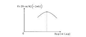
- the discloser of the present application considers that when the radial thickness dimension of the conducting wire portion is changed to various values, the cross-sectional area of the conducting wire portion when the thickness dimension is obtained and the cross-sectional area of the conducting wire portion when the thickness dimension is obtained.
- the multiplication value is a value corresponding to the torque constant of the rotary electric machine, it is possible to increase the torque of the rotary electric machine by adopting the radial thickness dimension of the conducting wire portion where the multiplication value is maximum. it can.
- the radial thickness dimension of the conducting wire portion is the thickness dimension of each thickness dimension when the radial thickness dimension of the conducting wire portion is changed to various values.
- the thickness dimension is set so that the product of the cross-sectional area of the conducting wire portion and the amount of magnetic flux of the magnet at the operating point of the magnet portion at the time of the thickness dimension is the maximum value or a value close to the maximum value. As a result, the torque of the rotary electric machine can be increased.
- each of the conducting wires is square.
- the discloser of the present application has a square cross-sectional shape of the conducting wire portion so that the radial thickness dimension of the conducting wire portion in which the multiplication value is the maximum value or a vicinity of the maximum value is secured to some extent in the radial direction. It was confirmed by calculation and experiment that the thickness dimension was to be. Therefore, in the means 2, the cross-sectional shape of each conducting wire portion is square. As a result, the torque of the rotary electric machine can be increased.
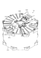
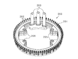
- FIG. 1 is a perspective view showing the entire rotary electric machine according to the first embodiment.
- FIG. 2 is a plan view of the rotary electric machine.
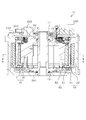
- FIG. 3 is a vertical cross-sectional view of the rotary electric machine.
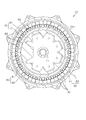
- FIG. 4 is a cross-sectional view of the rotary electric machine.
- FIG. 5 is an exploded sectional view of the rotary electric machine.
- FIG. 6 is a cross-sectional view of the rotor.
- FIG. 7 is a partial cross-sectional view showing the cross-sectional structure of the magnet unit.
- FIG. 8 is a diagram showing the relationship between the electric angle and the magnetic flux density of the magnet of the embodiment.
- FIG. 9 is a diagram showing the relationship between the electric angle and the magnetic flux density of the magnet of the comparative example.
- FIG. 10 is a perspective view of the stator unit.
- FIG. 11 is a vertical cross-sectional view of the stator unit.
- FIG. 12 is a perspective view of the core assembly viewed from one side in the axial direction.
- FIG. 13 is a perspective view of the core assembly viewed from the other side in the axial direction.
- FIG. 14 is a cross-sectional view of the core assembly.
- FIG. 15 is an exploded sectional view of the core assembly.
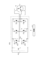
- FIG. 16 is a circuit diagram showing a connection state of partial windings in each of the three-phase windings.
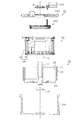
- FIG. 17 is a side view showing the first coil module and the second coil module side by side in comparison.
- FIG. 18 is a side view showing the first partial winding and the second partial winding side by side in comparison.
- FIG. 19 is a diagram showing the configuration of the first coil module.
- FIG. 20 is a sectional view taken along line 20-20 in FIG. 19 (a).
- FIG. 21 is a perspective view showing the configuration of the insulating cover.
- FIG. 22 is a diagram showing the configuration of the second coil module.
- FIG. 23 is a cross-sectional view taken along the line 23-23 in FIG. 22 (a).
- FIG. 24 is a perspective view showing the configuration of the insulating cover.
- FIG. 25 is a diagram showing overlapping positions of film materials in a state where the coil modules are arranged in the circumferential direction.
- FIG. 26 is a plan view showing the assembled state of the first coil module with respect to the core assembly.
- FIG. 27 is a plan view showing the assembled state of the first coil module and the second coil module with respect to the core assembly.
- FIG. 28 is a vertical cross-sectional view showing a fixed state by the fixing pin.
- FIG. 29 is a diagram for explaining a configuration relating to a winding end portion of the coil module.
- FIG. 30 is a perspective view of the bus bar module.
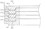
- FIG. 31 is a cross-sectional view showing a part of the vertical cross section of the bus bar module.
- FIG. 32 is a perspective view showing a state in which the bus bar module is assembled to the stator holder.
- FIG. 33 is a vertical cross-sectional view of a fixed portion for fixing the bus bar module.
- FIG. 34 is a vertical cross-sectional view showing a state in which the relay member is attached to the housing cover.
- FIG. 35 is a perspective view of the relay member.
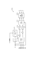
- FIG. 36 is an electric circuit diagram showing a control system of a rotary electric machine.
- FIG. 37 is a functional block diagram showing a current feedback control process by the control device.
- FIG. 38 is a functional block diagram showing torque feedback control processing by the control device.
- FIG. 39 is a partial cross-sectional view showing the cross-sectional structure of the magnet unit in the modified example.
- FIG. 40 is a diagram showing a configuration of a stator unit having an inner rotor structure.
- FIG. 41 is a cross-sectional view of the rotor and the stator according to the second embodiment.
- FIG. 42 is a diagram showing the electrical configuration of one partial winding.
- FIG. 43 is a diagram showing a magnetic circuit of a rotor and a stator.
- FIG. 44 is a cross-sectional view showing a part of the rotor and the stator developed in the circumferential direction.
- FIG. 45 is a diagram showing a demagnetization curve of a magnet.
- FIG. 46 is a diagram showing the relationship between the magnetic flux amount and the magnetomotive force of the magnet.
- FIG. 47 is a diagram showing an air gap corresponding to each thickness dimension of the intermediate conductor portion.
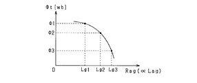
- FIG. 48 is a diagram showing the relationship between the magnetic flux amount and the magnetomotive force of the magnet and the permeance straight line.
- FIG. 49 is a diagram showing the relationship between the amount of magnetic flux flowing through the magnetic circuit and the magnetic resistance.
- FIG. 50 is a diagram showing the relationship between the torque constant and the magnetic resistance.
- FIG. 51 is a diagram showing a cross-sectional shape of an intermediate conductor portion having the same phase.
- FIG. 52 is a diagram showing an electrical configuration of one conductor.
- the rotary electric machine in this embodiment is used as a vehicle power source, for example.
- the rotary electric machine can be widely used for industrial use, vehicle use, home appliance use, OA equipment use, game machine use, and the like.
- parts that are the same or equal to each other are designated by the same reference numerals in the drawings, and the description thereof will be incorporated for the parts having the same reference numerals.
- the rotary electric machine 10 is a synchronous multi-phase AC motor and has an outer rotor structure (abduction structure).
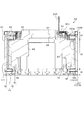
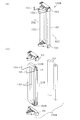
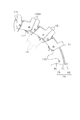
- the outline of the rotary electric machine 10 is shown in FIGS. 1 to 5.
- FIG. 1 is a perspective view showing the entire rotary electric machine 10
- FIG. 2 is a plan view of the rotary electric machine 10
- FIG. 3 is a vertical sectional view of the rotary electric machine 10 (3-3 line sectional view of FIG. 2).
- FIG. 4 is a cross-sectional view of the rotary electric machine 10 (4-4 line sectional view of FIG. 3)
- FIG. 5 is an exploded cross-sectional view showing the components of the rotary electric machine 10 in an exploded manner.
- the direction in which the rotary shaft 11 extends is the axial direction
- the direction in which the rotary shaft 11 extends radially from the center of the rotary shaft 11 is the radial direction
- the direction in which the rotary shaft 11 extends in a circumferential shape is the circumference. The direction.
- the rotary electric machine 10 is roughly classified into a rotary electric machine main body having a rotor 20, a stator unit 50 and a bus bar module 200, and a housing 241 and a housing cover 242 provided so as to surround the rotary electric machine main body.
- Each of these members is arranged coaxially with respect to the rotating shaft 11 integrally provided on the rotor 20, and is assembled in the axial direction in a predetermined order to form the rotating electric machine 10.
- the rotating shaft 11 is supported by a pair of bearings 12 and 13 provided on the stator unit 50 and the housing 241 respectively, and can rotate in that state.
- the bearings 12 and 13 are radial ball bearings having, for example, an inner ring, an outer ring, and a plurality of balls arranged between them.
- the rotation of the rotating shaft 11 causes, for example, the axle of the vehicle to rotate.
- the rotary electric machine 10 can be mounted on a vehicle by fixing the housing 241 to a vehicle body frame or the like.
- the stator unit 50 is provided so as to surround the rotary shaft 11, and the rotor 20 is arranged on the radial outer side of the stator unit 50.
- the stator unit 50 has a stator 60 and a stator holder 70 assembled radially inside the stator 60.
- the rotor 20 and the stator 60 are arranged so as to face each other in the radial direction with an air gap in between, and the rotor 20 rotates integrally with the rotating shaft 11 so that the rotor 20 is radially outside the stator 60. Rotate.
- the rotor 20 corresponds to the "field magnet” and the stator 60 corresponds to the "armor”.
- FIG. 6 is a vertical cross-sectional view of the rotor 20.
- the rotor 20 has a substantially cylindrical rotor carrier 21 and an annular magnet unit 22 fixed to the rotor carrier 21.
- the rotor carrier 21 has a cylindrical portion 23 having a cylindrical shape and an end plate portion 24 provided at one end in the axial direction of the cylindrical portion 23, and is configured by integrating them. ..
- the rotor carrier 21 functions as a magnet holding member, and the magnet unit 22 is annularly fixed inside the cylindrical portion 23 in the radial direction.
- a through hole 24a is formed in the end plate portion 24, and the rotating shaft 11 is fixed to the end plate portion 24 by a fastener 25 such as a bolt in a state of being inserted through the through hole 24a.
- the rotating shaft 11 has a flange 11a extending in a direction intersecting (orthogonal) in the axial direction, and the rotor carrier 21 is attached to the rotating shaft 11 in a state where the flange 11a and the end plate portion 24 are surface-bonded. Is fixed.
- the magnet unit 22 includes a cylindrical magnet holder 31, a plurality of magnets 32 fixed to the inner peripheral surface of the magnet holder 31, and on both sides in the axial direction opposite to the end plate portion 24 of the rotor carrier 21. It has a fixed end plate 33.
- the magnet holder 31 has the same length dimension as the magnet 32 in the axial direction.
- the magnet 32 is provided in the magnet holder 31 in a state of being surrounded from the outside in the radial direction.
- the magnet holder 31 and the magnet 32 are fixed in contact with the end plate 33 at one end in the axial direction.
- the magnet unit 22 corresponds to the "magnet portion".
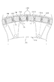
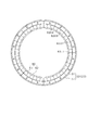
- FIG. 7 is a partial cross-sectional view showing the cross-sectional structure of the magnet unit 22.
- the direction of the easy axis of magnetization of the magnet 32 is indicated by an arrow.
- the magnets 32 are arranged side by side so that the polarities alternate along the circumferential direction of the rotor 20.
- the magnet unit 22 has a plurality of magnetic poles in the circumferential direction.
- the magnet 32 is a polar anisotropy permanent magnet, and uses a sintered neodymium magnet having an intrinsic coercive force of 400 [kA / m] or more and a residual magnetic flux density Br of 1.0 [T] or more. It is configured.
- the peripheral surface on the inner side of the magnet 32 in the radial direction is the magnetic flux acting surface 34 on which magnetic flux is exchanged.
- the direction of the easy magnetization axis is different between the d-axis side (the part closer to the d-axis) and the q-axis side (the part closer to the q-axis), and the direction of the easy magnetization axis is the d-axis on the d-axis side.
- the direction of the easy magnetization axis is perpendicular to the q-axis. In this case, an arcuate magnet magnetic path is formed along the direction of the easy magnetization axis.
- the magnet 32 is configured to be oriented on the d-axis side, which is the center of the magnetic pole, so that the direction of the easy-magnetizing axis is parallel to the d-axis as compared with the side of the q-axis, which is the magnetic pole boundary.
- the magnet magnetic path length is longer than the thickness dimension in the radial direction of the magnet 32.
- the permeance of the magnet 32 is increased, and it is possible to exert the same ability as a magnet having a large amount of magnets while having the same amount of magnets.
- the magnet 32 constitutes one magnetic pole by forming a set of two magnets adjacent to each other in the circumferential direction. That is, the plurality of magnets 32 arranged in the circumferential direction in the magnet unit 22 have split surfaces on the d-axis and the q-axis, respectively, and the magnets 32 are arranged in contact with each other or in close proximity to each other. ..
- the magnet 32 has an arcuate magnet magnetic path, and on the q-axis, the north and south poles of the magnets 32 adjacent to each other in the circumferential direction face each other. Therefore, it is possible to improve the permeance in the vicinity of the q-axis. Further, since the magnets 32 on both sides of the q-axis attract each other, each of these magnets 32 can maintain a contact state with each other. Therefore, it also contributes to the improvement of permeance.
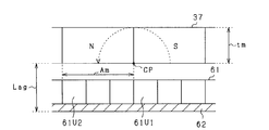
- each magnet 32 causes a magnetic flux to flow between adjacent N and S poles in an arc shape, so that the magnet path is longer than, for example, a radial anisotropic magnet. Therefore, as shown in FIG. 8, the magnetic flux density distribution is close to that of a sine wave. As a result, unlike the magnetic flux density distribution of the radial anisotropic magnet shown as a comparative example in FIG. 9, the magnetic flux can be concentrated on the center side of the magnetic pole, and the torque of the rotary electric machine 10 can be increased. .. Further, it can be confirmed that the magnet unit 22 of the present embodiment has a difference in the magnetic flux density distribution as compared with the conventional magnets having a Halbach array. In FIGS.
- the horizontal axis represents the electric angle and the vertical axis represents the magnetic flux density. Further, in FIGS. 8 and 9, 90 ° on the horizontal axis indicates the d-axis (that is, the center of the magnetic pole), and 0 ° and 180 ° on the horizontal axis indicate the q-axis.
- each magnet 32 having the above configuration the magnet magnetic flux on the d-axis is strengthened in the magnet unit 22, and the change in magnetic flux near the q-axis is suppressed.
- the magnet unit 22 it is possible to preferably realize the magnet unit 22 in which the change in surface magnetic flux from the q-axis to the d-axis is gentle at each magnetic pole.
- the sine wave matching factor of the magnetic flux density distribution may be, for example, a value of 40% or more. By doing so, it is possible to surely improve the amount of magnetic flux in the central portion of the waveform as compared with the case of using a radial alignment magnet or a parallel alignment magnet having a sinusoidal matching factor of about 30%. Further, if the sine wave matching factor is 60% or more, the amount of magnetic flux in the central portion of the waveform can be surely improved as compared with the magnetic flux concentrated arrangement such as the Halbach array.
- the magnetic flux density changes sharply near the q-axis.
- the steeper the change in the magnetic flux density the more the eddy current increases in the stator winding 61 of the stator 60, which will be described later. Further, the change in magnetic flux on the stator winding 61 side is also steep.
- the magnetic flux density distribution is a magnetic flux waveform close to a sine wave. Therefore, the change in the magnetic flux density near the q-axis is smaller than the change in the magnetic flux density of the radial anisotropic magnet. As a result, the generation of eddy current can be suppressed.
- the magnet 32 has a concave portion 35 formed on the outer peripheral surface in the radial direction in a predetermined range including the d-axis, and a concave portion 36 is formed in a predetermined range including the q-axis on the inner peripheral surface on the inner side in the radial direction. ing.
- the magnetic path is shortened near the d-axis on the outer peripheral surface of the magnet 32, and the magnetic path is shortened near the q-axis on the inner peripheral surface of the magnet 32. .. Therefore, in consideration of the fact that it becomes difficult to generate a sufficient magnet magnetic flux in a place where the magnet magnetic path length is short in the magnet 32, the magnet is deleted in the place where the magnet magnetic flux is weak.
- the magnet unit 22 may be configured to use the same number of magnets 32 as the magnetic poles.
- the magnet 32 is provided as one magnet between the d-axis which is the center of each magnetic pole in two magnetic poles adjacent to each other in the circumferential direction.
- the magnet 32 has a configuration in which the center in the circumferential direction is the q-axis and the magnet 32 has a split surface on the d-axis.
- the magnet 32 may have a configuration in which the center in the circumferential direction is the d-axis instead of the configuration in which the center in the circumferential direction is the q-axis.
- an annular magnet connected in an annular shape may be used.
- a resolver 41 as a rotation sensor is provided at an end portion (upper end portion in the drawing) opposite to the coupling portion with the rotor carrier 21 on both sides of the rotation shaft 11 in the axial direction.
- the resolver 41 includes a resolver rotor fixed to the rotating shaft 11 and a resolver stator arranged so as to face each other on the radial outer side of the resolver rotor.
- the resolver rotor has a disk ring shape, and is provided coaxially with the rotating shaft 11 in a state where the rotating shaft 11 is inserted.
- the resolver stator has a stator core and a stator coil, and is fixed to the housing cover 242.
- FIG. 10 is a perspective view of the stator unit 50
- FIG. 11 is a vertical sectional view of the stator unit 50. Note that FIG. 11 is a vertical cross-sectional view at the same position as in FIG.
- the stator unit 50 has a stator 60 and a stator holder 70 on the inner side in the radial direction thereof. Further, the stator 60 has a stator winding 61 and a stator core 62. Then, the stator core 62 and the stator holder 70 are integrated and provided as a core assembly CA, and a plurality of partial windings 151 constituting the stator winding 61 are assembled to the core assembly CA.
- the stator winding 61 corresponds to the "armature winding”
- the stator core 62 corresponds to the "armature core”
- the stator holder 70 corresponds to the "armature holding member”.
- the core assembly CA corresponds to the "support member”.
- FIG. 12 is a perspective view of the core assembly CA viewed from one side in the axial direction
- FIG. 13 is a perspective view of the core assembly CA viewed from the other side in the axial direction
- FIG. 14 is a cross section of the core assembly CA.
- FIG. 15 is an exploded cross-sectional view of the core assembly CA.
- the core assembly CA has a stator core 62 and a stator holder 70 assembled radially inside the stator core 62 as described above. So to speak, the stator core 62 is integrally assembled on the outer peripheral surface of the stator holder 70.
- the stator core 62 is configured as a core sheet laminated body in which core sheets 62a made of magnetic steel sheets, which are magnetic materials, are laminated in the axial direction, and has a cylindrical shape having a predetermined thickness in the radial direction.
- a stator winding 61 is assembled on the radial outer side of the stator core 62 on the rotor 20 side.
- the outer peripheral surface of the stator core 62 has a curved surface without unevenness.
- the stator core 62 functions as a back yoke.
- the stator core 62 is configured by, for example, a plurality of core sheets 62a punched out in an annular plate shape and laminated in the axial direction. However, a stator core 62 having a helical core structure may be used.
- stator core 62 having a helical core structure
- a strip-shaped core sheet is used, and the core sheet is wound in an annular shape and laminated in the axial direction to form a cylindrical stator core 62 as a whole. Has been done.
- the stator 60 has a slotless structure that does not have teeth for forming slots, and the configuration uses any of the following (A) to (C). It may be a thing.
- a conductor-to-conductor member is provided between each conductor portion (intermediate conductor portion 152 described later) in the circumferential direction, and the width dimension of the conductor-to-conductor member at one magnetic pole in the circumferential direction is provided as the conductor-to-conductor member. Wt, the saturation magnetic flux density of the conductor-to-conductor member is Bs, the width dimension of the magnet 32 at one magnetic pole in the circumferential direction is Wm, and the residual magnetic flux density of the magnet 32 is Br.
- a magnetic material is used.
- a conductor-to-conductor member is provided between each conductor portion (intermediate conductor portion 152) in the circumferential direction, and a non-magnetic material is used as the conductor-to-conductor member.
- the stator 60 has a configuration in which no interconductor member is provided between each conductor portion (intermediate conductor portion 152) in the circumferential direction.
- the stator holder 70 has an outer cylinder member 71 and an inner cylinder member 81, and the outer cylinder member 71 is radially outside and the inner cylinder member 81 is radially inside. It is configured by being assembled integrally.
- Each of these members 71 and 81 is made of, for example, a metal such as aluminum or cast iron, or carbon fiber reinforced plastic (CFRP).
- the outer cylinder member 71 is a cylindrical member having a perfectly circular curved surface on both the outer peripheral surface and the inner peripheral surface, and an annular flange 72 extending inward in the radial direction is formed on one end side in the axial direction.
- the flange 72 is formed with a plurality of protrusions 73 extending inward in the radial direction at predetermined intervals in the circumferential direction (see FIG. 13).
- facing surfaces 74 and 75 facing the inner cylinder member 81 in the axial direction are formed on one end side and the other end side in the axial direction, respectively, and the facing surfaces 74 and 75 are annular.
- An annular grooves 74a and 75a extending to the surface are formed.
- the inner cylinder member 81 is a cylindrical member having an outer diameter dimension smaller than the inner diameter dimension of the outer cylinder member 71, and its outer peripheral surface is a perfect circular curved surface concentric with the outer cylinder member 71.
- An annular flange 82 extending radially outward is formed on one end side of the inner cylinder member 81 in the axial direction.
- the inner cylinder member 81 is assembled to the outer cylinder member 71 in a state of being in axial contact with the facing surfaces 74 and 75 of the outer cylinder member 71. As shown in FIG. 13, the outer cylinder member 71 and the inner cylinder member 81 are assembled to each other by fasteners 84 such as bolts.
- a plurality of protruding portions 83 extending inward in the radial direction are formed at predetermined intervals in the circumferential direction, and the axial end faces of the protruding portions 83 and the outer cylinder are formed.
- the protruding portions 73, 83 are fastened to each other by the fastener 84 in a state where the protruding portions 73 of the member 71 are overlapped with each other.
- the outer cylinder member 71 and the inner cylinder member 81 are assembled to each other, there is an annular gap between the inner peripheral surface of the outer cylinder member 71 and the outer peripheral surface of the inner cylinder member 81. It is formed, and the gap space serves as a refrigerant passage 85 through which a refrigerant such as cooling water flows.
- the refrigerant passage 85 is provided in an annular shape in the circumferential direction of the stator holder 70. More specifically, the inner cylinder member 81 is provided with a passage forming portion 88 that protrudes inward in the radial direction on the inner peripheral side thereof and has an inlet side passage 86 and an outlet side passage 87 formed therein.
- Each of the passages 86 and 87 is open to the outer peripheral surface of the inner cylinder member 81. Further, on the outer peripheral surface of the inner cylinder member 81, a partition portion 89 for partitioning the refrigerant passage 85 into an inlet side and an outlet side is provided. As a result, the refrigerant flowing in from the inlet side passage 86 flows in the refrigerant passage 85 in the circumferential direction, and then flows out from the outlet side passage 87.
- FIG. 12 shows an entrance opening 86a leading to the entrance side passage 86 and an exit opening 87a leading to the exit side passage 87.
- the inlet side passage 86 and the outlet side passage 87 communicate with the inlet port 244 and the outlet port 245 (see FIG. 1) attached to the housing cover 242, and the refrigerant enters and exits through the respective ports 244 and 245. It has become like.
- Sealing materials 101 and 102 for suppressing leakage of the refrigerant in the refrigerant passage 85 are provided at the joint portion between the outer cylinder member 71 and the inner cylinder member 81 (see FIG. 15).
- the sealing materials 101 and 102 are, for example, O-rings, which are housed in the annular grooves 74a and 75a of the outer cylinder member 71 and are provided in a state of being compressed by the outer cylinder member 71 and the inner cylinder member 81. There is.
- the inner cylinder member 81 has an end plate portion 91 on one end side in the axial direction, and the end plate portion 91 has a hollow tubular boss portion 92 extending in the axial direction. It is provided.
- the boss portion 92 is provided so as to surround the insertion hole 93 for inserting the rotating shaft 11.
- the boss portion 92 is provided with a plurality of fastening portions 94 for fixing the housing cover 242.
- the end plate portion 91 is provided with a plurality of support column portions 95 extending in the axial direction on the radial outer side of the boss portion 92.
- the support column 95 is a portion that serves as a fixing portion for fixing the bus bar module 200, and the details thereof will be described later.
- the boss portion 92 is a bearing holding member for holding the bearing 12, and the bearing 12 is fixed to the bearing fixing portion 96 provided on the inner peripheral portion thereof (see FIG. 3).
- recesses 105 and 106 used for fixing a plurality of coil modules 150 are formed in the outer cylinder member 71 and the inner cylinder member 81.
- a plurality of axial end faces of the inner cylinder member 81 are provided at equal intervals in the circumferential direction.
- a recess 105 is formed.
- a plurality of recesses 106 are formed at equal intervals in the circumferential direction on the axial end surface of the outer cylinder member 71, specifically, the axially outer end surface of the flange 72.
- These recesses 105 and 106 are provided so as to line up on a virtual circle concentric with the core assembly CA.
- the recesses 105 and 106 are provided at the same positions in the circumferential direction, and the intervals and the number thereof are also the same.
- the stator core 62 is assembled in a state where a compressive force in the radial direction is generated with respect to the stator holder 70 in order to secure the strength of assembly with respect to the stator holder 70.
- the stator core 62 is fitted and fixed to the stator holder 70 with a predetermined tightening allowance by shrink fitting or press fitting.
- the stator core 62 and the stator holder 70 are assembled in a state where one of them causes radial stress to the other.
- stator 60 when increasing the torque of the rotary electric machine 10, for example, it is conceivable to increase the diameter of the stator 60, and in such a case, the stator is used to strengthen the coupling of the stator core 62 to the stator holder 70. The tightening force of the core 62 is increased. However, if the compressive stress (in other words, the residual stress) of the stator core 62 is increased, there is a concern that the stator core 62 may be damaged.
- stator core 62 and the stator holder 70 are fitted and fixed to each other with a predetermined tightening allowance.
- a regulating portion is provided to regulate the displacement of the stator core 62 in the circumferential direction by engaging in the circumferential direction. That is, as shown in FIGS. 12 to 14, a plurality of engaging portions as regulating portions are engaged between the stator core 62 and the outer cylinder member 71 of the stator holder 70 in the radial direction at predetermined intervals in the circumferential direction.
- a member 111 is provided, and the engaging member 111 suppresses the displacement of the stator core 62 and the stator holder 70 in the circumferential direction.
- a recess may be provided in at least one of the stator core 62 and the outer cylinder member 71, and the engaging member 111 may be engaged in the recess. 782 is formed.
- a convex portion may be provided on either the stator core 62 or the outer cylinder member 71.
- the stator core 62 and the stator holder 70 are fitted and fixed with a predetermined tightening allowance, and mutual circumferential displacement is regulated by the regulation of the engaging member 111. It is provided in a state of being. Therefore, even if the tightening allowance in the stator core 62 and the stator holder 70 is relatively small, the displacement of the stator core 62 in the circumferential direction can be suppressed. Further, since the desired displacement suppressing effect can be obtained even if the tightening allowance is relatively small, damage to the stator core 62 due to an excessively large tightening allowance can be suppressed. As a result, the displacement of the stator core 62 can be appropriately suppressed.
- An annular internal space is formed on the inner peripheral side of the inner cylinder member 81 so as to surround the rotating shaft 11, and in the internal space, for example, electrical components constituting an inverter as a power converter are arranged. May be good.
- the electric component is, for example, an electric module in which a semiconductor switching element or a capacitor is packaged.
- the plurality of protruding portions 83 may be eliminated, or the protruding height of the protruding portions 83 may be reduced, thereby expanding the internal space on the inner peripheral side of the inner cylinder member 81. It is possible.
- stator winding 61 assembled to the core assembly CA The state in which the stator winding 61 is assembled to the core assembly CA is as shown in FIGS. 10 and 11, and the stator is radially outside the core assembly CA, that is, radially outside the stator core 62.
- a plurality of partial windings 151 constituting the winding 61 are assembled in a state of being arranged in the circumferential direction.
- the stator winding 61 has a plurality of phase windings, and the phase windings of each phase are arranged in a predetermined order in the circumferential direction to form a cylindrical shape (annular shape).
- the stator winding 61 has a three-phase phase winding by using the U-phase, V-phase, and W-phase phase windings.
- the stator 60 includes a portion corresponding to the coil side CS that faces the magnet unit 22 in the rotor 20 in the axial direction in the axial direction, and a coil end that is outside the coil side CS in the axial direction. It has a part corresponding to CE.
- the stator core 62 is provided in a range corresponding to the coil side CS in the axial direction.
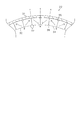
- each phase winding of each phase has a plurality of partial windings 151 (see FIG. 16), and the partial windings 151 are individually provided as coil modules 150. That is, the coil module 150 is configured by integrally providing partial windings 151 in the phase windings of each phase, and the stator winding 61 is configured by a predetermined number of coil modules 150 according to the number of poles. There is. By arranging the coil modules 150 (partial winding 151) of each phase in a predetermined order in the circumferential direction, the conductors of each phase are arranged in a predetermined order in the coil side CS of the stator winding 61. It has become.
- FIG. 10 shows the arrangement order of the U-phase, V-phase, and W-phase conductors in the coil side CS. In the present embodiment, the number of magnetic poles is 24, but the number is arbitrary.
- the phase windings of each phase are configured by connecting the partial windings 151 of each coil module 150 in parallel or in series for each phase.
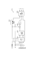
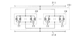
- FIG. 16 is a circuit diagram showing a connection state of the partial winding 151 in each of the three-phase windings.
- FIG. 16 shows a state in which the partial windings 151 in the phase windings of each phase are connected in parallel.
- the coil module 150 is assembled on the radial outer side of the stator core 62.
- the coil module 150 is assembled in a state in which both ends in the axial direction are projected outward in the axial direction (that is, the coil end CE side) from the stator core 62. That is, the stator winding 61 has a portion corresponding to the coil end CE protruding outward in the axial direction from the stator core 62, and a portion corresponding to the coil side CS on the inner side in the axial direction. ..
- the coil module 150 has two types of shapes, one of which has a shape in which the partial winding 151 is bent in the radial direction, that is, toward the stator core 62 in the coil end CE.
- the partial winding 151 is not bent inward in the radial direction and has a shape extending linearly in the axial direction.
- the partial winding 151 having a bent shape on both ends in the axial direction is referred to as a "first partial winding 151A”
- the coil module 150 having the first partial winding 151A is referred to as a "first coil”. Also referred to as "module 150A”.
- the partial winding 151 having no bending shape on both ends in the axial direction is also referred to as a "second partial winding 151B", and the coil module 150 having the second partial winding 151B is also referred to as a "second coil module 150B”. ..
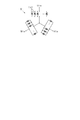
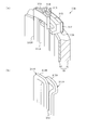
- FIG. 17 is a side view showing the first coil module 150A and the second coil module 150B side by side in comparison
- FIG. 18 shows the first partial winding 151A and the second partial winding 151B side by side. It is a side view which shows by side-by-side comparison.
- the coil modules 150A and 150B and the partial windings 151A and 151B have different axial lengths and different end shapes on both sides in the axial direction.
- the first partial winding 151A has a substantially C shape in the side view
- the second partial winding 151B has a substantially I shape in the side view.
- the first partial winding 151A is equipped with insulating covers 161, 162 as “first insulating covers” on both sides in the axial direction
- the second partial winding 151B is equipped with “second insulating covers” on both sides in the axial direction. Insulation covers 163 and 164 are attached.
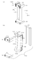
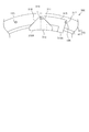
- FIG. 19A is a perspective view showing the configuration of the first coil module 150A
- FIG. 19B is a perspective view showing the components of the first coil module 150A in an exploded manner
- 20 is a cross-sectional view taken along the line 20-20 in FIG. 19A.
- the first coil module 150A has a first partial winding 151A formed by multiple winding of a wire rod CR and an axial direction in the first partial winding 151A thereof. It has insulating covers 161, 162 attached to one end side and the other end side.
- the insulating covers 161, 162 are formed of an insulating material such as synthetic resin.
- the first partial winding 151A has a pair of intermediate conductors 152 provided in parallel and linearly with each other, and a pair of crossovers 153A connecting the pair of intermediate conductors 152 at both ends in the axial direction. , These pair of intermediate conductor portions 152 and the pair of crossover portions 153A form an annular shape.
- the pair of intermediate conductors 152 are provided so as to be separated by a predetermined coil pitch, and the intermediate conductors 152 of the partial winding 151 of the other phase can be arranged between the pair of intermediate conductors 152 in the circumferential direction. It has become.
- the pair of intermediate conductors 152 are provided so as to be separated by two coil pitches, and one intermediate conductor 152 in the other two-phase partial winding 151 is arranged between the pair of intermediate conductors 152. It is configured to be.
- the pair of crossover portions 153A have the same shape on both sides in the axial direction, and both are provided as portions corresponding to the coil end CE (see FIG. 11). Each crossover portion 153A is provided so as to be bent in a direction orthogonal to the intermediate conductor portion 152, that is, in a direction orthogonal to the axial direction.
- the first partial winding 151A has crossovers 153A on both sides in the axial direction
- the second partial winding 151B has crossovers 153B on both sides in the axial direction.
- the crossover portions 153A and 153B of these partial windings 151A and 151B are different in shape from each other, and in order to clarify the distinction, the crossover portion 153A of the first partial winding 151A is referred to as "first crossover portion 153A”.
- the crossover portion 153B of the second partial winding 151B is also referred to as "second crossover portion 153B".
- the intermediate conductors 152 are provided as coil side conductors arranged one by one in the circumferential direction in the coil side CS. Further, the crossover portions 153A and 153B are provided as coil end conductor portions in the coil end CE for connecting the intermediate conductor portions 152 having the same phase at two positions different in the circumferential direction.
- the first partial winding 151A is formed by multiple windings of the conducting wire material CR so that the cross section of the conducting wire gathering portion becomes a quadrangle.
- FIG. 20 shows a cross section of the intermediate conducting wire portion 152, and the conducting wire material CR is multiplely wound around the intermediate conducting wire portion 152 so as to be arranged in the circumferential direction and the radial direction. That is, in the first partial winding 151A, the conductors CR are arranged in a plurality of rows in the circumferential direction and in a plurality of rows in the radial direction in the intermediate conductor portion 152 so that the cross section becomes substantially rectangular. It is formed.
- the tip of the first crossover 153A is configured to be multiplely wound so that the conductor CRs are aligned in the axial direction and the radial direction due to the bending in the radial direction.
- the first partial winding 151A is configured by winding the conductor CR by concentric winding.
- the method of winding the conductor CR is arbitrary, and instead of concentric winding, the conductor CR may be wound multiple times by alpha winding.
- the end of the conductor CR is formed from one of the first crossovers 153A (the upper first crossover 153A in FIG. 19B). It is pulled out, and its ends are winding ends 154 and 155.
- the winding end portions 154 and 155 are portions at which the conductor material CR is wound at the beginning and the winding end, respectively.
- One of the winding ends 154 and 155 is connected to the current input / output terminal, and the other is connected to the neutral point.
- each intermediate conductor portion 152 is provided with a sheet-shaped insulating coating 157 covered.
- FIG. 19A shows the first coil module 150A in a state where the intermediate conductor portion 152 is covered with the insulating coating 157 and the intermediate conductor portion 152 is present inside the insulating coating 157.
- the corresponding portion is referred to as an intermediate conductor portion 152 (the same applies to FIG. 22 (b) described later).
- the insulating coating 157 uses a film material FM having at least the length of the insulating coating range in the intermediate conductor portion 152 as an axial dimension, and the film material FM is wound around the intermediate conductor portion 152. It is provided.
- the film material FM is made of, for example, a PEN (polyethylene naphthalate) film. More specifically, the film material FM includes a film base material and an adhesive layer provided on one side of both sides of the film base material and having foamability. Then, the film material FM is wound around the intermediate conductor portion 152 in a state of being adhered by the adhesive layer. It is also possible to use a non-foaming adhesive as the adhesive layer.
- the intermediate conductor portion 152 has a substantially rectangular cross section due to the conductor CRs being arranged in the circumferential direction and the radial direction, and the film material FM is formed around the intermediate conductor portion 152.
- the insulating coating 157 is provided by covering the peripheral ends in an overlapping state.
- the film material FM is a rectangular sheet whose vertical dimension is longer than the axial length of the intermediate conductor portion 152 and whose horizontal dimension is longer than one peripheral length of the intermediate conductor portion 152, and is adapted to the cross-sectional shape of the intermediate conductor portion 152. It is wound around the intermediate conductor portion 152 with a crease.
- the gap between the conductor material CR of the intermediate conductor portion 152 and the film base material is filled by foaming in the adhesive layer. Further, in the overlapping portion OL of the film material FM, the peripheral ends of the film material FM are joined by an adhesive layer.
- an insulating coating 157 is provided so as to cover all of the two circumferential side surfaces and the two radial side surfaces.
- the insulating coating 157 surrounding the intermediate conductor portion 152 has a film on one of the two circumferential side surfaces of the intermediate conductor portion 152, that is, the portion of the partial winding 151 of the other phase facing the intermediate conductor portion 152.
- An overlapping portion OL in which the material FM overlaps is provided.
- the pair of intermediate conductors 152 are provided with overlapping portions OL on the same side in the circumferential direction.
- the range is from the intermediate conductor portion 152 to the portion of the first crossover portion 153A on both sides in the axial direction covered by the insulating covers 161, 162 (that is, the portion inside the insulating covers 161, 162).
- the insulating coating 157 is provided.
- the range of AX1 is a portion not covered by the insulating covers 161, 162, and the insulating coating 157 is provided in a range extended vertically from the range AX1. ..
- the insulating cover 161 is mounted on the first crossover 153A on one axial side of the first partial winding 151A, and the insulating cover 162 is mounted on the first crossover 153A on the other axial direction of the first partial winding 151A. Will be done. Of these, the configuration of the insulating cover 161 is shown in FIGS. 21 (a) and 21 (b). 21 (a) and 21 (b) are perspective views of the insulating cover 161 viewed from two different directions.
- the insulating cover 161 includes a pair of side surface portions 171 which are side surfaces in the circumferential direction, an outer surface portion 172 on the outer side in the axial direction, and an inner surface portion 173 on the inner side in the axial direction. It has a front surface portion 174 on the inner side in the radial direction.
- Each of these parts 171 to 174 is formed in a plate shape, and is connected to each other in a three-dimensional shape so that only the outer side in the radial direction is opened.
- Each of the pair of side surface portions 171 is provided so as to extend toward the axial center of the core assembly CA in a state of being assembled to the core assembly CA.
- the outer surface portion 172 is provided with an opening 175a for pulling out the winding end portion 154 of the first partial winding 151A, and the front portion 174 is provided with the winding end of the first partial winding 151A.
- An opening 175b for pulling out the portion 155 is provided. In this case, one winding end portion 154 is drawn out from the outer surface portion 172 in the axial direction, while the other winding end portion 155 is drawn out from the front surface portion 174 in the radial direction.
- the pair of side surface portions 171 have a semicircular shape extending in the axial direction at positions at both ends in the circumferential direction of the front surface portion 174, that is, at positions where the side surface portions 171 and the front surface portion 174 intersect.
- a recess 177 is provided.
- the outer surface portion 172 is provided with a pair of protrusions 178 extending in the axial direction at positions symmetrical with respect to the center line of the insulating cover 161 in the circumferential direction on both sides in the circumferential direction.
- the first crossover portion 153A of the first partial winding 151A has a curved shape that is convex in the radial direction, that is, toward the core assembly CA, out of the radial inside and outside. In such a configuration, a gap is formed between the first crossover portions 153A adjacent to each other in the circumferential direction so as to be wider toward the tip end side of the first crossover portion 153A.
- the recess 177 is provided on the side surface portion 171 of the insulating cover 161 at a position outside the curved portion of the first crossover portion 153A by utilizing the gap between the first crossover portions 153A arranged in the circumferential direction. It has a structure.
- a temperature detection unit may be provided in the first partial winding 151A.
- the insulating cover 161 may be provided with an opening for drawing out a signal line extending from the temperature detection unit.
- the temperature detection unit can be suitably housed in the insulating cover 161.
- the other insulating cover 162 in the axial direction has substantially the same configuration as the insulating cover 161.
- the insulating cover 162 has a pair of side surface portions 171, an outer surface portion 172 on the outer side in the axial direction, an inner surface portion 173 on the inner side in the axial direction, and a front surface portion 174 on the inner side in the radial direction, similarly to the insulating cover 161. .. Further, in the insulating cover 162, the pair of side surface portions 171 are provided with semicircular recesses 177 at positions at both ends in the circumferential direction of the front surface portion 174, and the outer surface portion 172 is provided with a pair of protrusions 178. .. The difference from the insulating cover 161 is that the insulating cover 162 does not have an opening for pulling out the winding ends 154 and 155 of the first partial winding 151A.
- the height dimension in the axial direction (that is, the width dimension in the axial direction in the pair of side surface portions 171 and the front surface portion 174) is different.
- the axial height dimension W11 of the insulating cover 161 and the axial height dimension W12 of the insulating cover 162 are W11> W12. That is, when the conductor material CR is wound multiple times, it is necessary to switch (lane change) the winding stage of the conductor material CR in a direction orthogonal to the winding winding direction (circling direction), which is caused by the switching. It is conceivable that the winding width will increase.
- the insulating cover 161 is a portion that covers the first crossover 153A on the side including the winding start and winding end of the conducting wire material CR, and includes the winding start and winding end of the conducting wire material CR.
- the winding allowance (overlapping allowance) of the conductor material CR is larger than that of the other portions, and as a result, the winding width may be increased.
- the axial height dimension W11 of the insulating cover 161 is larger than the axial height dimension W12 of the insulating cover 162.
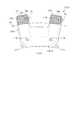
- FIG. 22A is a perspective view showing the configuration of the second coil module 150B
- FIG. 22B is a perspective view showing the components of the second coil module 150B in an exploded manner
- FIG. 23 is a cross-sectional view taken along the line 23-23 in FIG. 22 (a).
- the second coil module 150B includes a second partial winding 151B configured by multiple windings of the conductor CR as in the first partial winding 151A, and a second partial winding 151B thereof.
- the second partial winding 151B has insulating covers 163 and 164 attached to one end side and the other end side in the axial direction.
- the insulating covers 163 and 164 are formed of an insulating material such as synthetic resin.
- the second partial winding 151B has a pair of intermediate conductors 152 provided in parallel and linearly with each other, and a pair of second crossovers 153B connecting the pair of intermediate conductors 152 at both ends in the axial direction.
- the pair of intermediate conductors 152 and the pair of second crossovers 153B form an annular shape.
- the pair of intermediate conductors 152 in the second partial winding 151B has the same configuration as the intermediate conductors 152 in the first partial winding 151A.
- the pair of second crossover portions 153B has a different configuration from the first crossover portion 153A of the first partial winding 151A.
- the second crossover portion 153B of the second partial winding 151B is provided so as to extend linearly in the axial direction from the intermediate conductor portion 152 without being bent in the radial direction.
- the differences between the partial windings 151A and 151B are clearly shown in comparison.
- the end of the conductor CR is formed from one of the second crossovers 153B (the upper second crossover 153B in FIG. 22B) of the second crossovers 153B on both sides in the axial direction. It is pulled out, and its ends are winding ends 154 and 155. Then, in the second partial winding 151B as well as the first partial winding 151A, one of the winding ends 154 and 155 is connected to the current input / output terminal, and the other is connected to the neutral point. It has become.
- each intermediate conducting wire portion 152 is provided with a sheet-shaped insulating coating 157 covered.
- the insulating coating 157 uses a film material FM having at least the length of the insulating coating range in the intermediate conductor portion 152 as an axial dimension, and the film material FM is wound around the intermediate conductor portion 152. It is provided.
- the configuration of the insulating coating 157 is almost the same for the partial windings 151A and 151B. That is, as shown in FIG. 23, the film material FM is covered around the intermediate conductor portion 152 in a state where the end portions in the circumferential direction are overlapped.
- the insulating coating 157 is provided so as to cover all of the two circumferential side surfaces and the two radial side surfaces.
- the insulating coating 157 surrounding the intermediate conductor portion 152 has a film on one of the two circumferential side surfaces of the intermediate conductor portion 152, that is, the portion of the partial winding 151 of the other phase facing the intermediate conductor portion 152.
- An overlapping portion OL in which the material FM overlaps is provided.
- the pair of intermediate conductors 152 are provided with overlapping portions OL on the same side in the circumferential direction.
- the range is from the intermediate conductor portion 152 to the portion of the second crossover portion 153B on both sides in the axial direction covered by the insulating covers 163 and 164 (that is, the portion inside the insulating covers 163 and 164).
- the insulating coating 157 is provided.
- the range of AX2 is a portion not covered by the insulating covers 163 and 164, and the insulating coating 157 is provided in a range extended vertically from the range AX2. ..
- the insulating coating 157 is provided in a range including a part of the crossover portions 153A and 153B. That is, each of the partial windings 151A and 151B is provided with an insulating coating 157 at the intermediate conductor portion 152 and the portion of the crossover portions 153A and 153B that extends linearly following the intermediate conductor portion 152. However, since the axial lengths of the partial windings 151A and 151B are different, the axial range of the insulating coating 157 is also different.
- the insulating cover 163 is mounted on the second crossover 153B on one axial side of the second partial winding 151B, and the insulating cover 164 is mounted on the second crossover 153B on the other axial direction of the second partial winding 151B. Will be done. Of these, the configuration of the insulating cover 163 is shown in FIGS. 24 (a) and 24 (b). 24 (a) and 24 (b) are perspective views of the insulating cover 163 as viewed from two different directions.
- the insulating cover 163 includes a pair of side surface portions 181 which are side surfaces in the circumferential direction, an outer surface portion 182 on the outer side in the axial direction, and a front surface portion 183 on the inner side in the radial direction. It has a rear surface portion 184 on the outer side in the radial direction.
- Each of these portions 181 to 184 is formed in a plate shape, and is three-dimensionally connected to each other so that only the inner side in the axial direction is opened.
- Each of the pair of side surface portions 181 is provided so as to extend toward the axial center of the core assembly CA in a state of being assembled to the core assembly CA.
- the front surface portion 183 is provided with an opening 185a for pulling out the winding end portion 154 of the second partial winding 151B, and the outer surface portion 182 is provided with the winding end of the second partial winding 151B.
- An opening 185b for pulling out the portion 155 is provided.
- the front surface portion 183 of the insulating cover 163 is provided with a protruding portion 186 that projects inward in the radial direction.
- the projecting portion 186 is provided at a central position between one end and the other end in the circumferential direction of the insulating cover 163 so as to project radially inward from the second crossover portion 153B.
- the protruding portion 186 has a tapered shape that tapers toward the inner side in the radial direction in a plan view, and a through hole 187 extending in the axial direction is provided at the tip portion thereof.
- the projecting portion 186 projects radially inward from the second crossover portion 153B and has a through hole 187 at a central position between one end and the other end in the circumferential direction of the insulating cover 163, the projecting portion 186 has a through hole 187.
- Its configuration is arbitrary. However, assuming an overlapping state with the insulating cover 161 on the inner side in the axial direction, it is desirable that the width is narrowed in the circumferential direction in order to avoid interference with the winding ends 154 and 155.
- the protruding portion 186 has a stepped thinness in the axial direction at the tip portion on the inner side in the radial direction, and a through hole 187 is provided in the thinned lower step portion 186a.
- This low step portion 186a corresponds to a portion where the height of the inner cylinder member 81 from the axial end face is lower than the height of the second crossover portion 153B in the assembled state of the second coil module 150B with respect to the core assembly CA. ..
- the protruding portion 186 is provided with a through hole 188 penetrating in the axial direction.
- the adhesive can be filled between the insulating covers 161 and 163 through the through holes 188.
- the other insulating cover 164 in the axial direction has substantially the same configuration as the insulating cover 163.
- the insulating cover 164 has a pair of side surface portions 181, an outer surface portion 182 on the outer side in the axial direction, a front surface portion 183 on the inner side in the radial direction, and a rear surface portion 184 on the outer side in the radial direction. It has a through hole 187 provided at the tip of the portion 186.
- the difference from the insulating cover 163 is that the insulating cover 164 does not have an opening for pulling out the winding ends 154 and 155 of the second partial winding 151B.
- the width dimensions of the pair of side surface portions 181 in the radial direction are different. Specifically, as shown in FIG. 17, the radial width dimension W21 of the side surface portion 181 of the insulating cover 163 and the radial width dimension W22 of the side surface portion 181 of the insulating cover 164 are W21> W22. .. That is, of the insulating covers 163 and 164, the insulating cover 163 is a portion that covers the second crossover 153B on the side including the winding start and winding end of the conducting wire material CR, and includes the winding start and winding end of the conducting wire material CR.
- the winding allowance (overlapping allowance) of the conductor material CR may be larger than that of the other portions, and as a result, the winding width may be increased.
- the radial width dimension W21 of the insulating cover 163 is larger than the radial width dimension W22 of the insulating cover 164.
- the inconvenience that the number of turns of the conducting wire CR is limited by the insulating covers 163 and 164 can be suppressed. ing.
- FIG. 25 is a diagram showing overlapping positions of the film material FM in a state where the coil modules 150A and 150B are arranged in the circumferential direction.
- the intermediate conductor portion 152 is overlapped with the portion facing the intermediate conductor portion 152 in the partial winding 151 of the other phase, that is, the circumferential side surface of the intermediate conductor portion 152.
- the film material FM is covered with the film material (see FIGS. 20 and 23).
- the overlapping portion OL of the film material FM is arranged on the same side (right side in the circumferential direction in the figure) on both sides in the circumferential direction. ing.
- the overlapping portions OL of the film material FM do not overlap each other in the circumferential direction.
- a maximum of three film material FMs are overlapped between the intermediate conductors 152 arranged in the circumferential direction.
- the axial lengths of the coil modules 150A and 150B are different from each other, and the shapes of the crossovers 153A and 153B of the partial windings 151A and 151B are different from each other. It is configured to be attached to the core assembly CA with the second crossover 153B of the second coil module 150B on the inside in the direction and on the outside in the axial direction.
- the insulating covers 161 to 164 the insulating covers 161 and 163 are vertically overlapped on one end side in the axial direction of the coil modules 150A and 150B, and the insulating covers 162 and 164 are vertically overlapped on the other end side in the axial direction. In this state, each of these insulating covers 161 to 164 is fixed to the core assembly CA.
- FIG. 26 is a plan view showing a state in which a plurality of insulating covers 161 are arranged in the circumferential direction in a state where the first coil module 150A is assembled to the core assembly CA
- FIG. 27 is a plan view showing the first coil module 150A and the first coil module 150A to the core assembly CA. It is a top view which shows the state which a plurality of insulating covers 161, 163 are arranged in the circumferential direction in the assembled state of 2 coil module 150B.
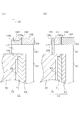
- FIG. 28A is a vertical cross-sectional view showing a state before fixing by the fixing pin 191 in the assembled state of the coil modules 150A and 150B with respect to the core assembly CA
- FIG. 28B is a vertical cross-sectional view showing the state before being fixed with respect to the core assembly CA. It is a vertical cross-sectional view which shows the state after being fixed by the fixing pin 191 in the assembled state of each coil module 150A, 150B.
- a plurality of insulating covers 161 are arranged so that the side surface portions 171 are in contact with each other or approach each other.
- Each insulating cover 161 is arranged so that the boundary line LB on which the side surface portions 171 face each other and the recess 105 on the axial end surface of the inner cylinder member 81 coincide with each other.
- each recess 177 of the insulating cover 161 forms a through hole portion extending in the axial direction, and the through hole portion is formed.
- the positions of the holes and the recesses 105 are matched.
- the second coil module 150B is further assembled to the integrated body of the core assembly CA and the first coil module 150A.
- a plurality of insulating covers 163 are arranged so that the side surface portions 181 are in contact with each other or approach each other.
- the crossover portions 153A and 153B are arranged so as to intersect each other on a circle in which the intermediate conductor portions 152 are lined up in the circumferential direction.
- the protruding portion 186 overlaps the insulating cover 161 in the axial direction, and the through hole 187 of the protruding portion 186 is axially connected to the through hole portion formed by each recess 177 of the insulating cover 161. Is placed.
- the protruding portion 186 of the insulating cover 163 is guided to a predetermined position by a pair of protruding portions 178 provided on the insulating cover 161 so that the through hole portion on the insulating cover 161 side and the recess 105 of the inner cylinder member 81 are guided.
- the positions of the through holes 187 on the insulating cover 163 side are aligned with those of the above. That is, in the state where the coil modules 150A and 150B are assembled to the core assembly CA, the recess 177 of the insulation cover 161 is located on the back side of the insulation cover 163, so that the protrusion 177 with respect to the recess 177 of the insulation cover 161.
- the fixing by the fixing pin 191 as a fixing member is performed in a state where the insulating cover 161 and the protruding portion 186 of the insulating cover 163 are engaged with each other at the overlapping portion. Will be done. More specifically, in a state where the recess 105 of the inner cylinder member 81, the recess 177 of the insulating cover 161 and the through hole 187 of the insulating cover 163 are aligned, the fixing pins are formed in the recesses 105, 177 and the through hole 187. 191 is inserted. As a result, the insulating covers 161 and 163 are integrally fixed to the inner cylinder member 81.
- the coil modules 150A and 150B adjacent to each other in the circumferential direction are fixed to the core assembly CA by a common fixing pin 191 at the coil end CE.
- the fixing pin 191 is preferably made of a material having good thermal conductivity, for example, a metal pin.
- the fixing pin 191 is assembled to the lower step portion 186a of the protruding portion 186 of the insulating cover 163.
- the upper end portion of the fixing pin 191 protrudes above the lower step portion 186a, but does not protrude above the upper surface (outer surface portion 182) of the insulating cover 163.
- the fixing pin 191 is longer than the axial height dimension of the overlapping portion between the insulating cover 161 and the protruding portion 186 (lower step portion 186a) of the insulating cover 163, and has a margin for protruding upward.
- the adhesive is filled through the through holes 188 provided in the insulating cover 163.
- the through hole 188 is shown in the range from the upper surface to the lower surface of the insulating cover 163, but in reality, the through hole 188 is formed in the thin plate portion formed by lightening or the like. It has a provided configuration.
- the fixing positions of the insulating covers 161 and 163 by the fixing pins 191 are the axial end faces of the stator holder 70 radially inside (left side in the drawing) from the stator core 62.
- the stator holder 70 is fixed by the fixing pin 191. That is, the first crossover portion 153A is fixed to the axial end face of the stator holder 70.
- the stator holder 70 is provided with the refrigerant passage 85, the heat generated in the first partial winding 151A is directly from the first crossover 153A to the vicinity of the refrigerant passage 85 of the stator holder 70. It is transmitted to.
- the fixing pin 191 is inserted into the recess 105 of the stator holder 70, and heat transfer to the stator holder 70 side is promoted through the fixing pin 191. With such a configuration, the cooling performance of the stator winding 61 is improved.
- 18 insulating covers 161 and 163 are arranged so as to be stacked inside and outside the axial direction in the coil end CE, while the same number as the respective insulating covers 161 and 163 are placed on the axial end faces of the stator holder 70.
- Recesses 105 are provided at 18 locations. The 18 recesses 105 are fixed by the fixing pin 191.
- the winding ends 154 and 155 are pulled out from the openings 175a and 175b from the insulating cover 161 and extend radially inward, and the winding ends 154 and 155 are drawn from the insulating cover 163 and the winding ends 154 and 155 are the openings 185a. , 185b is pulled out and extends inward in the radial direction.
- the winding ends 154 and 155 pulled out from the insulating cover 163 on the outer side in the axial direction extend so as to cross the insulating cover 161 on the outer side in the axial direction in the radial direction, and the intermediate portion thereof is insulated. It is fixed to the upper surface (outer surface portion 172) of the cover 161.
- the positions of the through holes 187 on the insulating cover 164 side match the through holes on the insulating cover 163 side and the recesses 106 on the outer cylinder member 71, and the recesses 106 and 177
- the fixing pin 191 By inserting the fixing pin 191 into the through hole 187, the insulating covers 162 and 164 are integrally fixed to the outer cylinder member 71.
- all the first coil modules 150A and 150B are attached to the outer peripheral side of the core assembly CA in advance, and then all the second coil modules 150B are assembled. It is preferable to perform fixing with the fixing pin 191.
- the two first coil modules 150A and the one second coil module 150B are first fixed to the core assembly CA with one fixing pin 191 and then the first coil module 150A is assembled. , The assembly of the second coil module 150B and the fixing by the fixing pin 191 may be repeated in this order.
- bus bar module 200 Next, the bus bar module 200 will be described.
- the bus bar module 200 is electrically connected to the partial winding 151 of each coil module 150 at the stator winding 61, and one end of the partial winding 151 of each phase is connected in parallel for each phase, and each of these partial windings is connected in parallel. It is a winding connecting member that connects the other end of 151 at a neutral point.
- FIG. 30 is a perspective view of the bus bar module 200
- FIG. 31 is a cross-sectional view showing a part of a vertical cross section of the bus bar module 200.
- the bus bar module 200 has an annular portion 201 forming an annular shape, a plurality of connection terminals 202 extending from the annular portion 201, and three input / output terminals 203 provided for each phase winding.
- the annular portion 201 is formed in an annular shape by, for example, an insulating member such as a resin.
- the annular portion 201 has a substantially annular plate shape and has laminated plates 204 laminated in multiple layers (five layers in the present embodiment) in the axial direction, and each of these laminated plates 204 Four bus bars 211 to 214 are provided so as to be sandwiched between them.
- Each of the bus bars 211 to 214 has an annular shape, and is composed of a U-phase bus bar 211, a V-phase bus bar 212, a W-phase bus bar 213, and a neutral point bus bar 214. ..
- the bus bars 211 to 214 are arranged in the annular portion 201 so as to face each other in the axial direction.
- Each laminated plate 204 and each bus bar 211 to 214 are joined to each other by an adhesive.
- connection terminals 202 are connected to the bus bars 211 to 214 so as to project outward from the annular portion 201 in the radial direction.
- a protrusion 201a extending in an annular shape is provided on the upper surface of the annular portion 201, that is, on the upper surface of the laminated plate 204 on the most surface layer side of the laminated plate 204 provided in the five layers.
- the bus bar module 200 may be provided with the bus bars 211 to 214 embedded in the annular portion 201, and the bus bars 211 to 214 arranged at predetermined intervals are integrally insert-molded. It may be a thing. Further, the arrangement of the bus bars 211 to 214 is not limited to the configuration in which all the bus bars are arranged in the axial direction and all the plate surfaces are oriented in the same direction. It may be configured to be lined up in a row, or to include those having different plate surface extending directions.
- each connection terminal 202 is provided so as to be aligned in the circumferential direction of the annular portion 201 and extend in the axial direction on the outer side in the radial direction.
- the connection terminal 202 includes a connection terminal connected to the U-phase bus bar 211, a connection terminal connected to the V-phase bus bar 212, a connection terminal connected to the W-phase bus bar 213, and a neutral point. Includes a connection terminal connected to the bus bar 214 for use.
- the number of connection terminals 202 is the same as the number of winding ends 154 and 155 of each partial winding 151 in the coil module 150, and each of these connection terminals 202 has winding ends 154 of each partial winding 151.
- the 155s are connected one by one.
- the bus bar module 200 is connected to the U-phase partial winding 151, the V-phase partial winding 151, and the W-phase partial winding 151, respectively.
- the input / output terminal 203 is made of, for example, a bus bar material, and is provided in a direction extending in the axial direction.
- the input / output terminal 203 includes a U-phase input / output terminal 203U, a V-phase input / output terminal 203V, and a W-phase input / output terminal 203W. These input / output terminals 203 are connected to the bus bars 211 to 213 for each phase in the annular portion 201. Through each of these input / output terminals 203, power is input / output from an inverter (not shown) to the phase windings of each phase of the stator winding 61.
- the bus bar module 200 may be integrally provided with a current sensor that detects the phase current of each phase.
- the bus bar module 200 is provided with a current detection terminal, and the detection result of the current sensor is output to a control device (not shown) through the current detection terminal.
- the annular portion 201 has a plurality of protruding portions 205 projecting to the inner peripheral side as fixed portions to the stator holder 70, and the protruding portions 205 are formed with through holes 206 extending in the axial direction. ing.
- FIG. 32 is a perspective view showing a state in which the bus bar module 200 is assembled to the stator holder 70
- FIG. 33 is a vertical cross-sectional view of a fixed portion for fixing the bus bar module 200. See FIG. 12 for the configuration of the stator holder 70 before assembling the bus bar module 200.
- the bus bar module 200 is provided on the end plate portion 91 so as to surround the boss portion 92 of the inner cylinder member 81.
- the bus bar module 200 is fixed to the stator holder 70 (inner cylinder member 81) by fastening fasteners 217 such as bolts in a state where the bus bar module 200 is positioned by assembling the inner cylinder member 81 to the support column 95 (see FIG. 12). ing.
- the end plate portion 91 of the inner cylinder member 81 is provided with a strut portion 95 extending in the axial direction. Then, the bus bar module 200 is fixed to the support portion 95 by the fastener 217 in a state where the support portion 95 is inserted into the through holes 206 provided in the plurality of protrusion portions 205.
- the bus bar module 200 is fixed by using the retainer plate 220 made of a metal material such as iron.
- the retainer plate 220 is between the fastened portion 222 having an insertion hole 221 through which the fastener 217 is inserted, the pressing portion 223 that presses the upper surface of the annular portion 201 of the bus bar module 200, and the fastened portion 222 and the pressing portion 223. It has a bend portion 224 provided in the.
- the fastener 217 is screwed to the support column 95 of the inner cylinder member 81 with the fastener 217 inserted into the insertion hole 221 of the retainer plate 220. Further, the pressing portion 223 of the retainer plate 220 is in contact with the upper surface of the annular portion 201 of the bus bar module 200. In this case, the retainer plate 220 is pushed downward in the drawing as the fastener 217 is screwed into the support column 95, and the annular portion 201 is pressed downward by the pressing portion 223 accordingly. Since the downward pressing force in the figure caused by the screwing of the fastener 217 is transmitted to the pressing portion 223 through the bend portion 224, the pressing portion 223 is pressed with the elastic force at the bend portion 224. ing.
- annular protrusion 201a is provided on the upper surface of the annular portion 201, and the tip of the retainer plate 220 on the pressing portion 223 side can come into contact with the protrusion 201a. As a result, it is possible to prevent the downward pressing force of the retainer plate 220 from escaping to the outside in the radial direction. That is, the pressing force generated by the screwing of the fastener 217 is properly transmitted to the pressing portion 223 side.
- the input / output terminal 203 is 180 degrees opposite to the inlet opening 86a and the outlet opening 87a leading to the refrigerant passage 85 in the circumferential direction. It is provided at the position where However, these input / output terminals 203 and the openings 86a and 87a may be provided together at the same position (that is, a close position).
- relay member 230 that electrically connects the input / output terminal 203 of the bus bar module 200 to the external device outside the rotary electric machine 10 will be described.
- the input / output terminal 203 of the bus bar module 200 is provided so as to project outward from the housing cover 242, and is connected to the relay member 230 on the outside of the housing cover 242.
- the relay member 230 is a member that relays the connection between the input / output terminals 203 for each phase extending from the bus bar module 200 and the power lines for each phase extending from an external device such as an inverter.
- FIG. 34 is a vertical cross-sectional view showing a state in which the relay member 230 is attached to the housing cover 242, and FIG. 35 is a perspective view of the relay member 230.
- a through hole 242a is formed in the housing cover 242, and the input / output terminal 203 can be pulled out through the through hole 242a.
- the relay member 230 has a main body portion 231 fixed to the housing cover 242 and a terminal insertion portion 232 to be inserted into the through hole 242a of the housing cover 242.
- the terminal insertion portion 232 has three insertion holes 233 through which the input / output terminals 203 of each phase are inserted one by one.
- the three insertion holes 233 have a long cross-sectional opening, and are formed side by side in directions in which the longitudinal directions are substantially the same.
- the relay bus bar 234 is bent and formed in a substantially L shape, and is fixed to the main body 231 by fasteners 235 such as bolts, and the input / output terminal 203 is inserted into the insertion hole 233 of the terminal insertion portion 232. It is fixed to the tip of the screw by a fastener 236 such as a bolt and a nut.
- power lines for each phase extending from the external device can be connected to the relay member 230, and power can be input and output to the input / output terminal 203 for each phase.
- FIG. 36 is an electric circuit diagram of the control system of the rotary electric machine 10
- FIG. 37 is a functional block diagram showing a control process by the control device 270.
- the stator winding 61 is composed of a U-phase winding, a V-phase winding, and a W-phase winding, and an inverter 260 corresponding to a power converter is connected to the stator winding 61.
- the inverter 260 is composed of a full bridge circuit having the same number of upper and lower arms as the number of phases, and a series connection body including an upper arm switch 261 and a lower arm switch 262 is provided for each phase.
- Each of these switches 261,262 is turned on and off by the driver 263, and the phase winding of each phase is energized by the on / off.
- Each switch 261,262 is composed of a semiconductor switching element such as a MOSFET or an IGBT.
- a charge supply capacitor 264 for supplying the electric charge required for switching to each switch 261,262 is connected in parallel with the series connection body of the switches 261,262.
- U-phase winding V-phase winding
- W-phase winding One ends of the U-phase winding, V-phase winding, and W-phase winding are connected to the intermediate connection points between the switches 261 and 262 of the upper and lower arms, respectively.
- Each of these phase windings is star-shaped (Y-connected), and the other end of each phase winding is connected to each other at a neutral point.
- the control device 270 includes a microcomputer composed of a CPU and various memories, and performs energization control by turning on / off each switch 261,262 based on various detection information in the rotary electric machine 10 and a request for power running drive and power generation. ..
- the detection information of the rotary electric machine 10 includes, for example, the rotation angle (electric angle information) of the rotor 20 detected by an angle detector such as a resolver, the power supply voltage (inverter input voltage) detected by the voltage sensor, and the current sensor. Includes the energizing current of each phase detected by.
- the control device 270 performs on / off control of each switch 261,262 by, for example, PWM control at a predetermined switching frequency (carrier frequency) or rectangular wave control.
- the control device 270 may be a built-in control device built in the rotary electric machine 10 or an external control device provided outside the rotary electric machine 10.
- the rotary electric machine 10 of the present embodiment since the rotary electric machine 10 of the present embodiment has a slotless structure (teethless structure), the inductance of the stator 60 is reduced and the electrical time constant is reduced, and the electrical time constant is reduced. Under the situation where the constant is small, it is desirable to increase the switching frequency (carrier frequency) and increase the switching speed.
- the charge supply capacitor 264 since the charge supply capacitor 264 is connected in parallel to the series connection of the switches 261,262 of each phase, the wiring inductance becomes low, and an appropriate surge is performed even in a configuration in which the switching speed is increased. Countermeasures are possible.
- the high potential side terminal of the inverter 260 is connected to the positive electrode terminal of the DC power supply 265, and the low potential side terminal is connected to the negative electrode terminal (ground) of the DC power supply 265.
- the DC power supply 265 is composed of, for example, an assembled battery in which a plurality of single batteries are connected in series. Further, a smoothing capacitor 266 is connected in parallel with the DC power supply 265 to the high potential side terminal and the low potential side terminal of the inverter 260.
- FIG. 37 is a block diagram showing a current feedback control process for controlling each phase current of the U, V, and W phases.
- the current command value setting unit 271 uses a torque ⁇ dq map, and is based on the power running torque command value or the power generation torque command value for the rotary electric machine 10 and the electric angular velocity ⁇ obtained by time-differentiating the electric angle ⁇ . , The d-axis current command value and the q-axis current command value are set.
- the power generation torque command value is, for example, a regenerative torque command value when the rotary electric machine 10 is used as a power source for a vehicle.
- the dq conversion unit 272 sets the current detection values (three phase currents) by the current sensors provided for each phase as the d-axis in the field direction (direction of an axis of a magnetic field, or field direction). It is converted into a d-axis current and a q-axis current, which are components of the dimensional rotation coordinate system.
- the d-axis current feedback control unit 273 calculates the d-axis command voltage as an operation amount for feedback-controlling the d-axis current to the d-axis current command value. Further, the q-axis current feedback control unit 274 calculates the q-axis command voltage as an operation amount for feedback-controlling the q-axis current to the q-axis current command value. In each of these feedback control units 273 and 274, the command voltage is calculated using the PI feedback method based on the deviation of the d-axis current and the q-axis current with respect to the current command value.
- the three-phase conversion unit 275 converts the d-axis and q-axis command voltages into U-phase, V-phase, and W-phase command voltages.
- Each of the above units 271 to 275 is a feedback control unit that performs feedback control of the fundamental wave current according to the dq conversion theory, and the U-phase, V-phase, and W-phase command voltages are feedback control values.
- the operation signal generation unit 276 uses a well-known triangular wave carrier comparison method to generate an operation signal of the inverter 260 based on a three-phase command voltage. Specifically, the operation signal generation unit 276 switches the upper and lower arms in each phase by PWM control based on the magnitude comparison between the signal obtained by standardizing the command voltage of the three phases with the power supply voltage and the carrier signal such as the triangular wave signal. Generates an operation signal (duty signal). The switch operation signal generated by the operation signal generation unit 276 is output to the driver 263 of the inverter 260, and the driver 263 turns on / off the switches 261,262 of each phase.
- This process is mainly used for the purpose of increasing the output of the rotary electric machine 10 and reducing the loss under operating conditions in which the output voltage of the inverter 260 becomes large, such as in a high rotation region and a high output region.
- the control device 270 selects and executes either the torque feedback control process or the current feedback control process based on the operating conditions of the rotary electric machine 10.
- FIG. 38 is a block diagram showing torque feedback control processing corresponding to the U, V, and W phases.
- the voltage amplitude calculation unit 281 is a command value of the magnitude of the voltage vector based on the power running torque command value or the power generation torque command value for the rotary electric machine 10 and the electric angular velocity ⁇ obtained by time-differentiating the electric angle ⁇ . Calculate the voltage amplitude command.
- the dq conversion unit 282 converts the current detection value by the current sensor provided for each phase into the d-axis current and the q-axis current.
- the torque estimation unit 283 calculates the torque estimation value corresponding to the U, V, and W phases based on the d-axis current and the q-axis current.
- the torque estimation unit 283 may calculate the voltage amplitude command based on the map information associated with the d-axis current, the q-axis current, and the voltage amplitude command.
- the torque feedback control unit 284 calculates the voltage phase command, which is the command value of the phase of the voltage vector, as the operation amount for feedback-controlling the torque estimation value to the power running torque command value or the generated torque command value.
- the torque feedback control unit 284 calculates the voltage phase command using the PI feedback method based on the deviation of the torque estimated value with respect to the power running torque command value or the generated torque command value.
- the operation signal generation unit 285 generates an operation signal of the inverter 260 based on the voltage amplitude command, the voltage phase command, and the electric angle ⁇ . Specifically, the operation signal generation unit 285 calculates a three-phase command voltage based on the voltage amplitude command, the voltage phase command, and the electric angle ⁇ , and the calculated three-phase command voltage is standardized by the power supply voltage. And, by PWM control based on the magnitude comparison with the carrier signal such as the triangular wave signal, the switch operation signal of the upper and lower arms in each phase is generated. The switch operation signal generated by the operation signal generation unit 285 is output to the driver 263 of the inverter 260, and the driver 263 turns on / off the switches 261,262 of each phase.
- the operation signal generation unit 285 is based on the pulse pattern information, the voltage amplitude command, the voltage phase command, and the electric angle ⁇ , which are map information related to the voltage amplitude command, the voltage phase command, the electric angle ⁇ , and the switch operation signal.
- the switch operation signal may be generated.
- the configuration of the magnet in the magnet unit 22 may be changed as follows.
- the direction of the easy-magnetizing axis of the magnet 32 is oblique with respect to the radial direction, and a linear magnet magnetic path is formed along the direction of the easy-magnetizing axis.
- the magnet path length of the magnet 32 can be made longer than the thickness dimension in the radial direction, and the permeance can be improved.
- the bending direction of the crossover 153 may be either inside or outside in the radial direction, and the first crossover 153A is bent toward the core assembly CA in relation to the core assembly CA. Or the first crossover 153A may be bent to the opposite side of the core assembly CA. Further, the second crossover portion 153B can be either inside or outside in the radial direction as long as it is in a state of straddling a part of the first crossover portion 153A in the circumferential direction on the outer side in the axial direction of the first crossover portion 153A. It may be folded.
- the partial winding 151 may not have two types of partial windings 151 (first partial winding 151A, second partial winding 151B), but may have one type of partial winding 151.
- the partial winding 151 may be formed so as to form a substantially L-shape or a substantially Z-shape when viewed from the side.
- the crossover 153 is bent either inside or outside in the radial direction on one end side in the axial direction, and the crossover 153 is radially formed on the other end side in the axial direction.
- the configuration is such that it is provided without being bent.
- the crossover 153 is bent in opposite directions in the radial direction on one end side in the axial direction and the other end side in the axial direction.
- the coil module 150 is fixed to the core assembly CA by the insulating cover that covers the crossover 153 as described above.
- all the partial windings 151 for each phase winding may be divided into a plurality of parallel connection groups, and the plurality of parallel connection groups may be connected in series. That is, all n partial windings 151 in each phase winding are divided into two sets of parallel connection groups of n / 2 pieces and three sets of parallel connection groups of n / 3 pieces each, and these are connected in series. It may be configured to connect.
- the stator winding 61 may be configured such that a plurality of partial windings 151 are all connected in series for each phase winding.
- the stator winding 61 in the rotary electric machine 10 may have a configuration having two-phase windings (U-phase winding and V-phase winding).
- a pair of intermediate conductors 152 are provided at a distance of one coil pitch, and the intermediate conductors 152 in the other one-phase partial winding 151 are provided between the pair of intermediate conductors 152. It is sufficient that one is arranged.
- FIG. 40A and 40 (b) are views showing the configuration of the stator unit 300 in the case of an inner rotor structure.
- FIG. 40A is a perspective view showing a state in which the coil modules 310A and 310B are assembled to the core assembly CA
- FIG. 40B is a partial winding 311A and 311B included in the coil modules 310A and 310B.
- the core assembly CA is configured by assembling the stator holder 70 to the outside in the radial direction of the stator core 62.
- a plurality of coil modules 310A and 310B are assembled inside the stator core 62 in the radial direction.
- the partial winding 311A has substantially the same configuration as the first partial winding 151A described above, and is bent toward the core assembly CA side (diameter outside) on both sides in the axial direction with the pair of intermediate conductor portions 312. It has a formed crossover portion 313A.
- the partial winding 311B has substantially the same configuration as the second partial winding 151B described above, and has a pair of intermediate conductor portions 312 and a crossover portion 313A on both sides in the axial direction in the circumferential direction on the outer side in the axial direction. It has a crossover portion 313B provided so as to straddle the above.
- An insulating cover 315 is attached to the crossover 313A of the partial winding 311A, and an insulating cover 316 is attached to the crossover 313B of the partial winding 311B.
- the insulating cover 315 is provided with semicircular recesses 317 extending in the axial direction on the side surfaces on both sides in the circumferential direction. Further, the insulating cover 316 is provided with a protruding portion 318 that protrudes radially outward from the crossover portion 313B, and a through hole 319 extending in the axial direction is provided at the tip of the protruding portion 318.
- the stator 60 used in the rotary electric machine 10 may have a protrusion (for example, a tooth) extending from the back yoke. Also in this case, the coil module 150 or the like may be assembled to the stator core as long as it is attached to the back yoke.
- the rotary electric machine is not limited to the one with a star-shaped connection, but may be one with a ⁇ connection.
- a rotating electric machine 10 instead of the rotating field type rotating electric machine having a field magnet as a rotor and an armature as a stator, a rotating armature type having an armature as a rotor and a field magnet as a stator. It is also possible to use a rotary armature.
- FIG. 41 shows a vertical sectional view of a rotor and a stator of a rotary electric machine according to the present embodiment.
- the rotary electric machine according to the present embodiment has an outer rotor structure as in the first embodiment.
- the magnet unit 22 of the rotor 20 has a cylindrical magnet holder 31 and a plurality of magnets 37 fixed to the inner peripheral surface of the magnet holder 31.
- the magnet holder 31 has the same length dimension as the magnet 37 in the axial direction.
- the magnet 37 is provided in the magnet holder 31 in a state of being surrounded from the outside in the radial direction.
- the magnet holder 31 and the magnet 37 are fixed in contact with an end plate (not shown) at one end in the axial direction.
- the magnets 37 are arranged side by side so that the polarities alternate along the circumferential direction of the rotor 20. As a result, the magnet unit 22 has a plurality of magnetic poles in the circumferential direction.
- the magnet 37 is a polar anisotropy permanent magnet, and a sintered neodymium magnet having an intrinsic coercive force of 400 [kA / m] or more and a residual magnetic flux density Br of 1.0 [T] or more is used. It is configured.
- the peripheral surface on the inner side of the magnet 37 in the radial direction is the magnetic flux acting surface on which magnetic flux is exchanged.
- the direction of the easy magnetization axis is different between the d-axis side and the q-axis side
- the direction of the easy-magnetization axis is parallel to the d-axis on the d-axis side
- the direction of the easy-magnetization axis is parallel to the d-axis side.
- the orientation is orthogonal to the q-axis. In this case, an arcuate magnet magnetic path is formed along the direction of the easy magnetization axis.
- the magnet 37 is configured to be oriented on the d-axis side, which is the center of the magnetic pole, so that the direction of the easy-magnetizing axis is parallel to the d-axis as compared with the side of the q-axis, which is the magnetic pole boundary.
- the magnet magnetic path length is longer than the radial thickness dimension of the magnet 37.
- the permeance of the magnet 37 is increased, and it is possible to exert the same ability as a magnet having a large amount of magnets while having the same amount of magnets.
- the multiplication value of the number of phases of the stator winding 61 and the number of magnetic poles of the magnet unit 22 is 48.
- the number of phases is 3
- the number of magnetic poles of the magnet unit 22 is 16.
- This configuration is for increasing the amount of magnetic flux of the magnet interlinking with the intermediate conducting wire portion 152 constituting the stator winding 61 to increase the torque of the rotary electric machine. That is, as the number of magnetic poles of the magnet unit increases, the width dimension in the circumferential direction per magnetic pole of the magnet unit tends to become smaller, and the magnetic path per magnetic pole tends to become shorter. Therefore, if the number of magnetic poles is too large, the amount of magnetic flux interlinking with the intermediate conducting wire portion 152 becomes small.
- the multiplication value is set to 48. As a result, it is possible to prevent the number of magnetic poles from becoming too large and suppress a decrease in the amount of magnetic flux of the magnet interlinking with the intermediate conductor portion 152. As a result, the torque of the rotary electric machine can be increased.
- the stator 60 has a stator winding 61 and a stator core 62. Also in the present embodiment, as in the first embodiment, a plurality of partial windings 151 constituting the stator winding 61 are assembled on the radial outer side of the stator core 62 in a state of being arranged in the circumferential direction.
- the pair of intermediate conductors 152 are provided so as to be separated by a predetermined coil pitch, and the intermediate conductors 152 of the partial winding 151 of the other phase can be arranged between the pair of intermediate conductors 152 in the circumferential direction. It has become.
- the pair of intermediate conductors 152 are provided so as to be separated by two coil pitches, and one intermediate conductor 152 in the other two-phase partial winding 151 is arranged between the pair of intermediate conductors 152. It is configured to be.
- the partial winding 151 is formed by winding the conducting wire material CR multiple times.
- the partial winding 151 of each phase is composed of a parallel connection body of a plurality of conductors CR.
- each conductor CR is composed of a parallel connection of a plurality of conductors TT (see FIGS. 51 and 52). This configuration is for reducing eddy current loss.
- FIG. 42 is a diagram showing an electrical connection relationship of a partial winding 151 of a certain phase.
- the partial winding 151 is formed by multiple windings of the conductor material CR so that the cross-sectional shape of each intermediate conductor portion 152 is square.
- FIG. 51 is a cross-sectional view of the intermediate conductor portion 152 for a predetermined one phase.
- the reason why the required cross-sectional shape is square will be described.
- FIG. 43 shows a magnetic circuit including the magnetomotive force Ft of the magnet unit 22, the reluctance Rag of the air gap between the magnet unit 22 and the stator core 62, and the reluctance Rcore of the stator core 62.
- the amount of magnetic flux ⁇ t flowing through this magnetic circuit is expressed by the following equation (eq1).
- Lag indicates the length of the air gap, which is the distance between the inner peripheral surface of the magnet 37 in the radial direction and the outer peripheral surface of the stator core 62 in the radial direction (see FIG. 44).
- ⁇ 0 indicates the magnetic permeability of the vacuum
- Am indicates the width dimension in the circumferential direction per magnetic pole of the magnet 37.
- the total value Ragt of the magnetic resistance shown in the above equation (eq2) is a value per unit length in the axial direction of the rotary electric machine.
- the magnet 37 has an easy-to-magnetize axis oriented in an arc shape with the orientation center CP set on the q-axis as the center.
- the intersection of the inner peripheral surface of the magnet 37 and the q-axis is the orientation center CP.
- FIG. 45 shows the demagnetization curve of the magnet 37.
- Br indicates the residual magnetic flux density per pole pair of the magnet 37
- bHc indicates the intrinsic coercive force per pole pair of the magnet 37.
- the value obtained by multiplying the residual magnetic flux density Br by the circumferential width dimension Am per pole of the magnet 37 is the amount of magnetic flux ⁇ t [wb] per unit length in the axial direction, as shown in the vertical axis of FIG.
- the value obtained by multiplying the intrinsic coercive force bHc by the magnetic path length Lm per pole pair of the magnet 37 is the magnetomotive force F [A] as shown on the horizontal axis of FIG.
- the thickness dimension in the radial direction of the conductor assembly portion of the intermediate conductor portion 152 is changed.
- the thickness dimension increases in the order of FIGS. 47 (a), (b), and (c), and is "Lg1 ⁇ Lg2 ⁇ Lg3".
- the cross-sectional areas of the intermediate conductor portions 152 in FIGS. 47 (a), (b), and (c) are S1, S2, and S3. Since Am is set to the same value in FIGS. 47 (a), (b), and (c), “S1 ⁇ S2 ⁇ S3”.
- the permeance straight line of the magnetic circuit including the intermediate conductor portion 152 having each cross-sectional area is as shown in FIG. 48.
- the amount of magnetic flux at the intersection of each permeance straight line and the demagnetization curve (specifically, the operating point) is defined as a first magnetic flux amount ⁇ 1, a second magnetic flux amount ⁇ 2, and a third magnetic flux amount ⁇ 3.
- Each magnetic flux amount ⁇ 1 to ⁇ 3 is a magnetic flux amount generated when the same voltage is applied to the intermediate conducting wire portion 152 having each cross-sectional area S1 to S3.
- the air gap Lag is increased and the magnetic resistance Ragt of the magnetic circuit is increased.
- the magnetoresistive Ragt increases, as shown in FIG. 49, the amount of magnetic flux interlinking with the intermediate conducting wire portion 152 decreases.
- the thickness dimension of the intermediate conductor portion 152 in the radial direction is changed to various values, the cross-sectional area of the intermediate conductor portion 152 and its thickness at the time when the thickness dimension is obtained.
- the radial thickness dimension of the intermediate conductor portion 152 at which the multiplication value is the maximum value or a vicinity of the maximum value is the thickness dimension in which the cross-sectional shape of the intermediate conductor portion 152 is square. Therefore, in the present embodiment, the cross-sectional shape of the intermediate conductor portion 152 is square.
- the radial thickness dimension of the intermediate conductor portion 152 whose multiplication value is near the maximum value is, for example, a thickness dimension in which the multiplication value is 95% or more of the maximum value and less than 100%. Is.
- FIG. 51 illustrates a circular shape as the cross-sectional shape of the conductor CR and the conductor TT, but the present invention is not limited to this. Further, FIG. 51 shows an example in which each conductor CR is composed of a parallel connection of seven conductors TT, but the present invention is not limited to this.
- each conductor TT constituting one intermediate conductor is the arrangement position of each conductor TT constituting the other intermediate conductor when viewed from the axial direction. It is the arrangement position when rotated 90 degrees in a specific rotation direction.
- FIG. 51 shows four intermediate conductors 152 of only the U phase among the U, V, and W phases, and these intermediate conductors 152 are referred to as first to fourth conductors 63U1 to 63U4. Further, in FIG. 51, for convenience, the stator core 52 and the like are shown in a straight line, and in order to make it easy to understand that they are rotated by 90 degrees, a specific one CA of each conductor material CR is used. It has hatching.
- the arrangement position of each conductor CR in the second conductor 63U2 is the arrangement position when the arrangement position of each conductor CR in the first conductor 63U1 is rotated 90 degrees in the specific rotation direction when viewed from the axial direction. ing.
- the second conductor portion 63U2 and the first conductor portion 63U1 form one partial winding 151.
- the direction of the current flowing through each conductor CR of the second conductor 63U2 is opposite to the direction of the current flowing through each conductor CR of the first conductor 63U1.
- the arrangement position of each conductor CR in the third conductor 63U3 is the arrangement position when the arrangement position of each conductor CR in the second conductor 63U2 is rotated 90 degrees in the specific rotation direction when viewed from the axial direction. ing.
- the direction of the current flowing through each of the conductors CR of the third conductor 63U3 is opposite to the direction of the current flowing through each of the conductors CR of the second conductor 63U2.
- the arrangement position of each conductor CR in the fourth conductor 63U4 is the arrangement position when the arrangement position of each conductor CR in the third conductor 63U3 is rotated 90 degrees in the specific rotation direction when viewed from the axial direction. ing.
- the fourth conductor portion 63U4 and the third conductor portion 63U3 form one partial winding 151.
- the direction of the current flowing through each conductor CR of the fourth conductor 63U4 is opposite to the direction of the current flowing through each conductor CR of the third conductor 63U3.
- FIG. 52 will be described by focusing on one conductor material CR constituting the first conductor portion 63U1 and the second conductor portion 63U2.
- This conductor CR is composed of a parallel connection of a plurality of conductors TT.
- the first end side of the parallel connector is electrically connected to the bus bar 211 on the inverter 260 side, and the second end side is electrically connected to the bus bar 214 on the neutral point side.
- a closed loop circuit is formed in the first conductor portion 63U1 and the second conductor portion 63U2.
- an electromotive voltage (induced voltage) corresponding to the time change rate of the interlinking magnetic flux is generated in the conducting wire TT.
- the amount of magnetic flux of the magnet interlinking with the conductor TT differs depending on the circumferential position of the conductor TT with respect to the magnet unit 22 and the radial position of the conductor TT with respect to the magnet unit 22. If the position with respect to the magnet unit 22 is different, the difference between the electromotive voltage generated in the portion constituting the first conductor portion 63U1 and the electromotive voltage generated in the portion constituting the second conductor portion 63U2 becomes large in the conductor material CR. , The circulating current flowing through the closed loop circuit may increase.
- the arrangement method shown in FIG. 51 is adopted. As a result, it is possible to realize a configuration in which it is easy to reduce the difference in electromotive voltage due to the difference in the circumferential direction and the radial direction position of the conducting wire TT with respect to the magnet unit 22. More specifically, according to the configuration shown in FIG. 51, the arrangement positions of the conductor TTs constituting the intermediate conductor portions 152 of the same phase adjacent to each other in the circumferential direction are all the same arrangement positions when viewed from the axial direction. , The difference in electromotive voltage generated in each conductor CR can be reduced. As a result, the circulating current flowing through the closed loop circuit can be reduced.
- the cross-sectional shape of the intermediate conductor portion 152 is square. Therefore, among the in-phase intermediate conductor portions 152 adjacent to each other in the circumferential direction, the radial thickness dimension of one intermediate conductor portion and the radial thickness dimension of the other intermediate conductor portion can be made equal. .. Thereby, when the arrangement method shown in FIG. 51 is adopted, the air gap between the outer peripheral surface of the stator core 62 and the inner peripheral surface of the magnet unit 22 can be made uniform in the circumferential direction.
- the magnet is not limited to the arc orientation, and may be, for example, a parallel orientation.
- the number of phases of the stator winding may be 6, and the number of magnetic poles of the magnet unit may be 8.
- disclosure in this specification is not limited to the illustrated embodiments.
- the disclosure includes exemplary embodiments and modifications by those skilled in the art based on them.
- disclosure is not limited to the parts and / or element combinations shown in the embodiments. Disclosure can be carried out in various combinations.
- the disclosure can have additional parts that can be added to the embodiment. Disclosures include those in which the parts and / or elements of the embodiment are omitted. Disclosures include the replacement or combination of parts and / or elements between one embodiment and another.
- the technical scope disclosed is not limited to the description of the embodiments. Some technical scopes disclosed are indicated by the claims description and should be understood to include all modifications within the meaning and scope equivalent to the claims statement.
Landscapes
- Engineering & Computer Science (AREA)
- Power Engineering (AREA)
- Iron Core Of Rotating Electric Machines (AREA)
- Permanent Magnet Type Synchronous Machine (AREA)
- Windings For Motors And Generators (AREA)
Abstract
La présente invention concerne une machine électrique rotative (10) qui présente une structure sans fente et comprend : des aimants de champ (20) qui comprennent des pièces d'aimant (22) ayant une pluralité de pôles magnétiques, dont les polarités alternent de manière circonférentielle ; et une armature (60) ayant des bobines d'armature à phases multiples (61). La bobine d'armature pour chaque phase comporte des sections de fil conducteur (152) disposées de manière axiale et alignées de manière circonférentielle. Parmi les dimensions d'épaisseur dans un cas où la dimension d'épaisseur radiale des sections de fil conducteur est changée en diverses valeurs, la dimension d'épaisseur radiale des sections de fil conducteur est définie comme étant une dimension d'épaisseur donnée à laquelle une valeur est la valeur maximale ou à proximité de la valeur maximale, une telle valeur trouvée en multipliant : la surface de section transversale des sections de fil conducteur lorsque la dimension d'épaisseur donnée est atteinte ; et la quantité de flux magnétique d'aimant au point d'action des pièces d'aimant lorsque la dimension d'épaisseur donnée est atteinte.
Priority Applications (3)
| Application Number | Priority Date | Filing Date | Title |
|---|---|---|---|
| DE112020005454.3T DE112020005454T5 (de) | 2019-11-07 | 2020-11-05 | Rotierende elektrische Maschine |
| CN202080077346.5A CN114641920B (zh) | 2019-11-07 | 2020-11-05 | 旋转电机 |
| US17/739,371 US12132364B2 (en) | 2019-11-07 | 2022-05-09 | Rotating electrical machine |
Applications Claiming Priority (2)
| Application Number | Priority Date | Filing Date | Title |
|---|---|---|---|
| JP2019-202681 | 2019-11-07 | ||
| JP2019202681A JP7404794B2 (ja) | 2019-11-07 | 2019-11-07 | 回転電機 |
Related Child Applications (1)
| Application Number | Title | Priority Date | Filing Date |
|---|---|---|---|
| US17/739,371 Continuation US12132364B2 (en) | 2019-11-07 | 2022-05-09 | Rotating electrical machine |
Publications (1)
| Publication Number | Publication Date |
|---|---|
| WO2021090884A1 true WO2021090884A1 (fr) | 2021-05-14 |
Family
ID=75848581
Family Applications (1)
| Application Number | Title | Priority Date | Filing Date |
|---|---|---|---|
| PCT/JP2020/041362 Ceased WO2021090884A1 (fr) | 2019-11-07 | 2020-11-05 | Machine électrique rotative |
Country Status (5)
| Country | Link |
|---|---|
| US (1) | US12132364B2 (fr) |
| JP (1) | JP7404794B2 (fr) |
| CN (1) | CN114641920B (fr) |
| DE (1) | DE112020005454T5 (fr) |
| WO (1) | WO2021090884A1 (fr) |
Families Citing this family (2)
| Publication number | Priority date | Publication date | Assignee | Title |
|---|---|---|---|---|
| FR3114454B1 (fr) * | 2020-09-22 | 2023-01-06 | Ntn Snr Roulements | Machine électrique à N phases |
| US11901780B2 (en) * | 2020-12-11 | 2024-02-13 | Mabuchi Motor Co., Ltd. | Resolver |
Citations (2)
| Publication number | Priority date | Publication date | Assignee | Title |
|---|---|---|---|---|
| JP2019106864A (ja) * | 2017-07-21 | 2019-06-27 | 株式会社デンソー | 回転電機 |
| JP2019122248A (ja) * | 2017-12-28 | 2019-07-22 | 株式会社デンソー | 回転電機 |
Family Cites Families (10)
| Publication number | Priority date | Publication date | Assignee | Title |
|---|---|---|---|---|
| JP3371314B2 (ja) * | 1995-03-24 | 2003-01-27 | セイコーエプソン株式会社 | Dcブラシレスモータおよび制御装置 |
| JP3508709B2 (ja) * | 2000-08-22 | 2004-03-22 | 国産電機株式会社 | 磁石界磁回転形回転電機 |
| JP5373375B2 (ja) | 2008-07-10 | 2013-12-18 | ミネベア株式会社 | スピンドルモータ |
| JP6579395B2 (ja) * | 2016-06-03 | 2019-09-25 | 株式会社デンソー | 回転電機 |
| US11843334B2 (en) | 2017-07-13 | 2023-12-12 | Denso Corporation | Rotating electrical machine |
| JP6885328B2 (ja) | 2017-07-21 | 2021-06-16 | 株式会社デンソー | 回転電機 |
| JP7006541B2 (ja) | 2017-12-28 | 2022-01-24 | 株式会社デンソー | 回転電機 |
| DE112018006699T5 (de) | 2017-12-28 | 2020-09-10 | Denso Corporation | Rotierende elektrische Maschine |
| WO2019131913A1 (fr) * | 2017-12-28 | 2019-07-04 | 株式会社デンソー | Machine électrique rotative |
| JP2019202681A (ja) | 2018-05-24 | 2019-11-28 | トヨタ自動車株式会社 | 電力変換器の車載構造 |
-
2019
- 2019-11-07 JP JP2019202681A patent/JP7404794B2/ja active Active
-
2020
- 2020-11-05 DE DE112020005454.3T patent/DE112020005454T5/de active Pending
- 2020-11-05 CN CN202080077346.5A patent/CN114641920B/zh active Active
- 2020-11-05 WO PCT/JP2020/041362 patent/WO2021090884A1/fr not_active Ceased
-
2022
- 2022-05-09 US US17/739,371 patent/US12132364B2/en active Active
Patent Citations (2)
| Publication number | Priority date | Publication date | Assignee | Title |
|---|---|---|---|---|
| JP2019106864A (ja) * | 2017-07-21 | 2019-06-27 | 株式会社デンソー | 回転電機 |
| JP2019122248A (ja) * | 2017-12-28 | 2019-07-22 | 株式会社デンソー | 回転電機 |
Also Published As
| Publication number | Publication date |
|---|---|
| CN114641920A (zh) | 2022-06-17 |
| JP2021078221A (ja) | 2021-05-20 |
| US20220263396A1 (en) | 2022-08-18 |
| DE112020005454T5 (de) | 2022-08-18 |
| CN114641920B (zh) | 2024-09-17 |
| JP7404794B2 (ja) | 2023-12-26 |
| US12132364B2 (en) | 2024-10-29 |
Similar Documents
| Publication | Publication Date | Title |
|---|---|---|
| WO2021220760A1 (fr) | Machine électrique rotative | |
| WO2022113935A1 (fr) | Moteur électrique | |
| WO2021112199A1 (fr) | Machine électrique tournante | |
| WO2021145350A1 (fr) | Induit et procédé de fabrication d'induit | |
| WO2022092148A1 (fr) | Machine électrique tournante | |
| WO2021235344A1 (fr) | Machine électrique rotative et procédé de fabrication de machine électrique rotative | |
| WO2021090884A1 (fr) | Machine électrique rotative | |
| CN114788136B (zh) | 旋转电机 | |
| WO2021090883A1 (fr) | Machine électrique rotative | |
| WO2022113936A1 (fr) | Machine dynamo-électrique | |
| WO2021220761A1 (fr) | Machine dynamo-électrique et son procédé de fabrication | |
| JP2021114819A (ja) | 電機子 | |
| WO2021095735A1 (fr) | Machine électrique tournante et fil conducteur | |
| WO2021095736A1 (fr) | Machine électrique tournante | |
| WO2021117789A1 (fr) | Machine électrique rotative | |
| WO2021090819A1 (fr) | Machine dynamo-électrique | |
| WO2021192864A1 (fr) | Machine électrique tournante | |
| WO2021112200A1 (fr) | Machine électrique rotative | |
| CN116998108A (zh) | 旋转电机以及旋转电机的控制方法 | |
| WO2021100786A1 (fr) | Machine électrique tournante |
Legal Events
| Date | Code | Title | Description |
|---|---|---|---|
| 121 | Ep: the epo has been informed by wipo that ep was designated in this application |
Ref document number: 20885756 Country of ref document: EP Kind code of ref document: A1 |
|
| 122 | Ep: pct application non-entry in european phase |
Ref document number: 20885756 Country of ref document: EP Kind code of ref document: A1 |