WO2021090889A1 - 体外矯正具 - Google Patents
体外矯正具 Download PDFInfo
- Publication number
- WO2021090889A1 WO2021090889A1 PCT/JP2020/041382 JP2020041382W WO2021090889A1 WO 2021090889 A1 WO2021090889 A1 WO 2021090889A1 JP 2020041382 W JP2020041382 W JP 2020041382W WO 2021090889 A1 WO2021090889 A1 WO 2021090889A1
- Authority
- WO
- WIPO (PCT)
- Prior art keywords
- members
- pair
- screw
- shaft
- extracorporeal
- Prior art date
- Legal status (The legal status is an assumption and is not a legal conclusion. Google has not performed a legal analysis and makes no representation as to the accuracy of the status listed.)
- Ceased
Links
Images









Classifications
-
- A—HUMAN NECESSITIES
- A61—MEDICAL OR VETERINARY SCIENCE; HYGIENE
- A61B—DIAGNOSIS; SURGERY; IDENTIFICATION
- A61B17/00—Surgical instruments, devices or methods
- A61B17/56—Surgical instruments or methods for treatment of bones or joints; Devices specially adapted therefor
- A61B17/58—Surgical instruments or methods for treatment of bones or joints; Devices specially adapted therefor for osteosynthesis, e.g. bone plates, screws or setting implements
- A61B17/68—Internal fixation devices, including fasteners and spinal fixators, even if a part thereof projects from the skin
- A61B17/70—Spinal positioners or stabilisers, e.g. stabilisers comprising fluid filler in an implant
- A61B17/7074—Tools specially adapted for spinal fixation operations other than for bone removal or filler handling
- A61B17/7076—Tools specially adapted for spinal fixation operations other than for bone removal or filler handling for driving, positioning or assembling spinal clamps or bone anchors specially adapted for spinal fixation
- A61B17/7077—Tools specially adapted for spinal fixation operations other than for bone removal or filler handling for driving, positioning or assembling spinal clamps or bone anchors specially adapted for spinal fixation for moving bone anchors attached to vertebrae, thereby displacing the vertebrae
-
- A—HUMAN NECESSITIES
- A61—MEDICAL OR VETERINARY SCIENCE; HYGIENE
- A61B—DIAGNOSIS; SURGERY; IDENTIFICATION
- A61B17/00—Surgical instruments, devices or methods
- A61B17/56—Surgical instruments or methods for treatment of bones or joints; Devices specially adapted therefor
- A61B17/58—Surgical instruments or methods for treatment of bones or joints; Devices specially adapted therefor for osteosynthesis, e.g. bone plates, screws or setting implements
- A61B17/68—Internal fixation devices, including fasteners and spinal fixators, even if a part thereof projects from the skin
- A61B17/70—Spinal positioners or stabilisers, e.g. stabilisers comprising fluid filler in an implant
- A61B17/7074—Tools specially adapted for spinal fixation operations other than for bone removal or filler handling
- A61B17/7076—Tools specially adapted for spinal fixation operations other than for bone removal or filler handling for driving, positioning or assembling spinal clamps or bone anchors specially adapted for spinal fixation
- A61B17/7077—Tools specially adapted for spinal fixation operations other than for bone removal or filler handling for driving, positioning or assembling spinal clamps or bone anchors specially adapted for spinal fixation for moving bone anchors attached to vertebrae, thereby displacing the vertebrae
- A61B17/7079—Tools requiring anchors to be already mounted on an implanted longitudinal or transverse element, e.g. where said element guides the anchor motion
-
- A—HUMAN NECESSITIES
- A61—MEDICAL OR VETERINARY SCIENCE; HYGIENE
- A61B—DIAGNOSIS; SURGERY; IDENTIFICATION
- A61B17/00—Surgical instruments, devices or methods
- A61B17/02—Surgical instruments, devices or methods for holding wounds open, e.g. retractors; Tractors
- A61B17/025—Joint distractors
- A61B2017/0256—Joint distractors for the spine
-
- A—HUMAN NECESSITIES
- A61—MEDICAL OR VETERINARY SCIENCE; HYGIENE
- A61B—DIAGNOSIS; SURGERY; IDENTIFICATION
- A61B17/00—Surgical instruments, devices or methods
- A61B17/56—Surgical instruments or methods for treatment of bones or joints; Devices specially adapted therefor
- A61B17/58—Surgical instruments or methods for treatment of bones or joints; Devices specially adapted therefor for osteosynthesis, e.g. bone plates, screws or setting implements
- A61B17/68—Internal fixation devices, including fasteners and spinal fixators, even if a part thereof projects from the skin
- A61B2017/681—Alignment, compression, or distraction mechanisms
Definitions
- the present invention corrects spinal deformity by a spinal deformity correction and fixation system including a vertebral fixation device fixed to each of a plurality of vertebrae and a rod member connected to the vertebral fixation device during spinal deformity correction and fixation surgery. It relates to an extracorporeal orthodontic appliance that can be corrected by an operation from outside the body to assist the correction and fixation at the time of fixing.
- spinal deformity that causes an abnormality in the spinal column is a disease in which the spinal column is deformed, and includes, for example, scoliosis, kyphosis, and kyphosis.
- Scoliosis is a disease in which the spinal column is twisted while the spinal column is curved laterally.
- Kyphosis is a disease in which the angle of thoracic kyphosis becomes extremely large or the lordosis of the lumbar spine is lost and deformed into kyphosis. Furthermore, scoliosis is a combination of scoliosis and kyphosis.
- spinal deformity correction and fixation surgery is an operation to correct and fix the deformed spinal column to a normal state or a state close to it by a spinal deformity correction and fixation system (internal implant material, so-called implant) described later, and posterior correction.
- Fixation or anterior orthodontic fusion is applied.
- posterior orthodontic fixation is performed as follows. That is, posterior orthodontic fusion involves positioning the patient in a prone position on the operating table and placing a surgical wound in the middle of the patient's back, or a minimally invasive percutaneous surgical wound, posterior to the spinal column. Expand the element. Subsequently, by attaching a spinal deformity correction and fixation system (see, for example, Patent Document 1) to the spinal column, the spinal deformity is three-dimensionally corrected and fixed in that state.
- a spinal deformity correction and fixation system see, for example, Patent Document 1
- a spinal deformity correction and fixation system includes, for example, a plurality of screw members screwed into the vertebral body via a pair of left and right vertebral arches of each vertebra of the spinal column, a hook member hooked on the vertebral arch or transverse process of each vertebra, and the like. And each screw member and each hook member, for example, those provided with a pair of rod members connected to a top open groove portion, extending along the axial direction of the spinal column, and arranged at intervals in the left-right direction of the patient. It has been adopted.
- a screw member and a hook member are used. , Fix each to multiple vertebrae to be corrected. Subsequently, the rod member is engaged with the top open groove portion of the screw member or the hook member. At this time, although the spinal column is in a deformed state, since the rod member extends linearly, it is very difficult to engage the rod member with the top open groove portion of the screw member and the hook member. Therefore, the surgeon uses a special surgical instrument to bend the rod member along the scoliosis of the spinal column.
- the bent rod is engaged with the top open groove portion of the screw member or hook member fixed to each vertebra so that the rod member does not come out of the top open groove portion of each screw member or hook member. Temporarily fix the set screw to the top open groove.
- the outer peripheral surface of the rod member is sandwiched by a special surgical instrument (rod gripper or the like) equivalent to pliers, and the surgical instrument is rotated by approximately 90 ° to move the rod member around its axis.
- An operation is performed to correct scoliosis including twisting of the spinal column by rotating it by approximately 90 °.
- a dedicated surgical instrument for example, for a plurality of screw members arranged along the axial direction of the spinal column, and for adjacent screw members arranged along the axial direction of the spinal column, etc.
- the rod member is curved along the scoliosis of the patient and is engaged with the top open groove of each screw member and each hook member. Since the rod member is scolioticly deformed including twisting, it is very difficult to engage the rod member with the top open groove portion of each screw member or hook member even in a curved state. Moreover, the longer the range of correction and fixation by the spinal deformity correction and fixation system, the more difficult it is to engage the rod member with the top open groove of each screw member or hook member, and as a result, the operation time becomes longer and the operation becomes longer. The burden on the person and the patient will increase.
- the outer peripheral surface of the rod member is firmly sandwiched by a special surgical instrument equivalent to a plier, and the rod member is rotated by approximately 90 ° to rotate the spinal column.
- the operation is performed to correct the scoliosis deformation including the twist of the patient, but when the rod member bent along the scoliosis deformation of the patient is rotated by approximately 90 ° around its axis, the rod member The curvature will be replaced by the patient's kyphosis and lordosis.
- this rod member may cause other inconveniences because it does not match the patient's physiological kyphosis and lordosis, and corrects the kyphosis and / or lordosis intended by the operator. It is necessary to take appropriate measures to implement it.
- the outer peripheral surface of the rod member is firmly sandwiched by a special surgical instrument equivalent to pliers and rotated by 90 °, so that the outer peripheral surface of the rod member is rotated by 90 °.
- a special surgical instrument equivalent to pliers there is a risk that the part pinched by the surgical instrument equivalent to pliers will be damaged.
- the rod member is temporarily fixed to the top open groove portion of each screw member or each hook member by a set screw, when the rod member is rotated, the outer peripheral surface of the rod member is connected to the set screw. There is a risk of damaging the contact area as well. As a result, these damaged sites are one of the factors that induce breakage of the rod member after being placed in the body.
- a direct compressive load is applied to the rotation operation of the rod member and the plurality of screw members arranged along the axial direction of the spinal column.
- An operation is performed to correct the lateral curvature of the spinal column by applying or applying a tensile load, but this correction operation directly applies a load to the implant of the spinal deformity correction and fixation system. It is difficult to apply a large corrective force to the spinal column.
- the present invention has been made in view of this point, and when the spinal deformity is corrected and fixed by the spinal deformity correction and fixation system, the corrective force is improved by correcting the spinal deformity by an operation from outside the body. It is possible to easily achieve the correction intended by the operator, and to eliminate the complexity of the correction and fixation operation by the spinal deformity correction and fixation system, which in turn reduces the burden on the patient.
- the purpose is to provide possible extracorporeal orthodontic appliances.
- the spinal deformity is corrected and fixed by a spinal deformity correction and fixation system including a vertebral fixture fixed to each vertebra of the spinal column and a rod member connected to the vertebral fixture
- the spinal deformity Is an extracorporeal correction tool that assists correction and fixation by the spinal deformity correction and fixation system by operating from outside the body.
- the vertebral fixation tools are provided in pairs on the left and right sides of one vertebra, and the extracorporeal
- the orthodontic tool is detachably attached to a pair of left and right vertebrae fixtures fixed to the one vertebra, and a shaft member extending toward the outside of the patient's body and the pair of left and right shaft members outside the patient's body.
- An extracorporeal correction tool (corresponding to the invention of claim 1), which comprises a lateral arm member which is connected and extends in the left-right direction.
- a shaft member is attached to each of a pair of left and right vertebrae fixtures fixed to one vertebra, and a pair of left and right shaft members are connected outside the body by a lateral arm member. With these pair of shaft members and lateral arm members, one vertebra can be firmly and accurately held outside the body.
- a pair of shaft members and lateral arm members are provided for the plurality of vertebrae, and the pair of shaft members and lateral arm members are individually operated outside the body, whereby the operator's intention for the plurality of vertebrae It is possible to perform all kinds of corrections, such as corrections that apply a compressive load or tensile load along the cranio-caudal direction, and rotational corrections.
- Each shaft member, each horizontal arm member, and each vertical arm member can hold the correction range in block units. Then, from the state where the correction range is maintained, for example, the surgeon (including the assistant) grasps the ends of each shaft member (for example, four shaft members) outside the body, and the trunk in the left-right direction of the patient. While correcting the position of the entire spinal column in the left-right direction so as to adjust the balance, it is possible to firmly correct the scoliosis including twist as the spinal column deformation in the intended manner.
- An extracorporeal orthodontic appliance (corresponding to the invention of claim 5).
- the extracorporeal orthodontic appliance according to item (5) by providing the bridge member, it is possible to construct a foundation that is the basis for correcting the spinal column deformation, particularly the lordotic deformation and the kyphosis deformation, outside the body.
- the in-vitro orthodontic appliance according to item (5) comprising a height adjusting means capable of freely adjusting the distance in the height direction between the head of the vertebral fixation device and the bridge member.
- An extracorporeal orthodontic appliance (corresponding to the invention of claim 6).
- the surgeon including an assistant
- the in-vitro orthodontic appliance according to the present invention corrects and fixes the spinal deformity by the spinal deformity correction and fixing system
- the surgeon intends to improve the corrective force by correcting the spinal deformity by an operation from outside the body. Correction can be easily achieved.
- the in-vitro orthodontic appliance according to the present invention can eliminate the complexity of the orthodontic fixation operation by the spinal deformity correction and fixation system, and as a result, the operation time can be significantly shortened, which in turn imposes a burden on the patient. It can be further reduced.
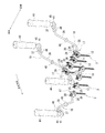
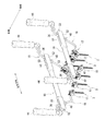
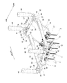
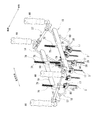
- FIG. 1 is a perspective view showing an overall outline of the in-vitro orthodontic appliance according to the first embodiment of the present invention.
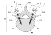
- FIG. 2 is a cross-sectional view of a spinal deformity correction and fixation system to which the in-vitro orthodontic appliance according to the first embodiment of the present invention is applied.
- FIG. 3 is a perspective view of a screw member of a spinal deformity correction and fixation system to which the extracorporeal orthodontic appliance according to the first embodiment of the present invention is applied.
- FIG. 4 is a perspective view of a connector member used in the extracorporeal orthodontic appliance according to the first embodiment of the present invention, in which the screw member is held by the connector member and the shaft member is supported. .. FIG.
- FIG. 5 is a perspective view of a single connector member used in the extracorporeal orthodontic appliance according to the first embodiment of the present invention.
- FIG. 6 is a perspective view showing a state in which the shaft member is fixed to the connector member by a set screw in the extracorporeal orthodontic appliance according to the first embodiment of the present invention.
- FIG. 7 is a perspective view showing a state in which lateral arm members are erected on a pair of left and right shaft members in the extracorporeal orthodontic appliance according to the first embodiment of the present invention.
- FIG. 8 is a perspective view showing a state in which a pair of vertical arm members are erected on a pair of shaft members adjacent to each other along the head-to-tail direction in the extracorporeal orthodontic appliance according to the first embodiment of the present invention.
- FIG. 6 is a perspective view showing a state in which the shaft member is fixed to the connector member by a set screw in the extracorporeal orthodontic appliance according to the first embodiment of the present invention.
- FIG. 7 is a perspective
- FIG. 9 is a plan view of the constituent members shown in FIG.
- FIG. 10 is a side view of the constituent member shown in FIG.
- FIG. 11 is a perspective view showing a state in which the shaft member is fixed to the connector member by a long bolt member, including a pair of vertical arm members and a pair of horizontal arm members, in the extracorporeal orthodontic appliance according to the first embodiment of the present invention.
- FIG. 12 is a perspective view showing a state in which a pair of bridge members are erected on a pair of lateral arm members adjacent to each other along the head-to-tail direction in the extracorporeal orthodontic appliance according to the first embodiment of the present invention.
- FIG. 12 is a perspective view showing a state in which a pair of bridge members are erected on a pair of lateral arm members adjacent to each other along the head-to-tail direction in the extracorporeal orthodontic appliance according to the first embodiment of the present invention.
- FIG. 13 is a perspective view showing a state in which the long bolt member is fixed to the bridge member in the extracorporeal orthodontic appliance according to the first embodiment of the present invention.
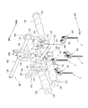
- FIG. 14 is a perspective view showing an overall outline of the extracorporeal orthodontic appliance according to the second embodiment of the present invention.
- FIG. 15 is a plan view of the extracorporeal orthodontic appliance according to the second embodiment of the present invention.
- FIG. 16 is a perspective view of a connector member used in the extracorporeal orthodontic appliance according to the second embodiment of the present invention, in which the screw member is held by the connector member and the shaft member is supported. ..
- FIG. 17 is a perspective view of a single connector member used in the extracorporeal orthodontic appliance according to the second embodiment of the present invention.
- FIG. 18 is a perspective view of a shaft member and a support member used in the extracorporeal orthodontic appliance according to the second embodiment of the present invention
- FIG. 18A shows a chrysanthemum seat formed on a cylindrical portion of the support member.
- (b) shows a support member having a cylindrical shape in which uneven portions are continuously formed along one direction.
- FIG. 19 is a perspective view of a grip member used in the extracorporeal orthodontic appliance according to the second embodiment of the present invention.
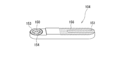
- FIG. 20 is a perspective view of a lateral arm member used in the extracorporeal orthodontic appliance according to the second embodiment of the present invention.
- FIG. 21 is a perspective view of a rack and pinion unit used in the extracorporeal orthodontic appliance according to the second embodiment of the present invention.
- FIG. 22 is a perspective view showing a state in which a connector member, a shaft member, and a lateral arm member are attached to a screw member in the extracorporeal orthodontic appliance according to the second embodiment of the present invention.
- FIG. 23 is a perspective view showing a state in which the grip member is further attached from the state of FIG. 22.
- FIG. 24 is a perspective view showing a state in which the rack and pinion unit is further attached from the state of FIG. 23.
- the in-vitro orthodontic appliances 1A and 1B according to the first and second embodiments of the present invention improve the orthodontic force by correction by an operation from outside the body when the spinal deformity is corrected and fixed by the spinal deformity correction and fixing system 2. While assisting the orthodontic fixation, the complexity of the orthodontic fixation operation can be eliminated.
- the spinal deformity correction and fixation system 2 is not shown as an overall image, but as shown in FIG. 2, a plurality of screw members 3 screwed into the vertebral body via a pair of left and right vertebral arches of each vertebra of the spinal column.
- the spinal deformity correction and fixation system 2 includes a hook member (not shown) fixed to the vertebra by hooking it on the vertebral arch root, vertebral arch, transverse process, etc. of the vertebra, and a pair of left and right rods, if necessary.
- Other constituent members such as a bridge member (not shown) arranged so as to bridge the members 5 and 5 are also adopted.
- the screw member 3, the hook member, and the like correspond to the vertebral fixture.
- the screw member 3 and the rod member 5 are made of a material having excellent biocompatibility such as titanium alloy.
- the rod member 5 is formed in a circular cross section.
- the length of the rod member 5 is appropriately set according to the degree of spinal deformation of the patient, that is, the correction range for spinal deformation (correction range in the axial direction).
- the screw members 3 and 3 are screwed into the vertebral body from behind the spinal column via a pair of left and right pedicles of each vertebra.
- the screw member 3 is also generally referred to as a pedicle screw or a pedicle screw.
- the screw member 3 includes a rod receiving portion 11 having a groove portion 10 for receiving the rod member 5, and a screw portion 12 connected to the rod receiving portion 11 and screwed into the vertebral body via the pedicle of the vertebra. There is.
- the rod receiving portion 11 is formed in a block shape having a U-shaped groove portion 10 having an open surface on the side opposite to the screw portion 12 side.
- the groove portion 10 is formed along the axial direction of the rod member 5.
- the rod member 5 is received in the groove portion 10.
- female screw portions 14 and 14 are formed on the inner wall surface of the wall portion facing the groove portion 10 as a boundary, respectively.
- the set screw 20 is screwed into the female screw portions 14, 14.
- the screw portion 12 is swingably connected to the rod receiving portion 11 with respect to the rod receiving portion 11 along the extending direction of the groove portion 10 (see the arrow in FIG. 3).
- the extracorporeal orthodontic appliance 1A according to the first embodiment will be described in detail with reference to FIGS. 1, 4 to 13.
- the screw member 3 shown in FIG. 4 will be described as appropriate with the screw portion 12 side as the lower side and the rod receiving portion 11 side as the upper side.
- the extracorporeal orthodontic tool 1A according to the first embodiment of the present invention is a pair of left and right screw members screwed into the vertebral body via a pair of left and right pedicles of one vertebra.
- Shaft members 18 and 18 that are detachably connected to 3 and 3 via connector members 100 and 100 and extend toward the outside of the patient's body and a pair of left and right shaft members 18 and 18 are erected outside the patient's body.
- a horizontal arm member 19 is provided.
- the connector member 17 is detachably attached to the rod receiving portion 11 (head) of the screw member 3.
- the connector member 17 is arranged around the rod receiving portion 11 of the screw member 3.
- the connector member 17 has a screw support portion 24 having a pair of support pieces 22 and 22 arranged at intervals from each other so as to support the rod receiving portion 11 of the screw member 3.
- a member restraint portion 26 having a U-shaped groove portion 25 having an open upper surface, and a rotating member 27 rotatably supported so as to bridge the tips of a pair of support pieces 22 and 22 of the screw support portion 24. , Is equipped.
- the screw support portion 24 and the member restraint portion 26 are integrally connected so as to partially overlap each other, and are formed so as to line up in a direction orthogonal to the extending direction of the groove portion 25 in a plan view. Has been done.
- the member restraint portion 26 has a U-shaped groove portion 25 having an open upper surface.
- the groove 25 is formed along the cranio-caudal direction of the patient.
- Female screw portions 28 and 28 are formed on the wall surfaces of the member restraint portion 26 facing each other via the groove portion 25, respectively.
- a set screw 29, a height adjusting rod member 96, or a long bolt member 78 is screwed into the female screw portions 28, 28.
- a polygonal hole (not shown) is exposed from the bottom opening of the groove 25 of the member restraint portion 26, and a dedicated surgical instrument is fitted into the polygonal hole to rotate the surgical instrument.
- the rotating member 27 rotates to open and close between the tips of the pair of support pieces 22 and 22 of the screw support portion 24.
- a support recess 30 for receiving one arc portion of the rod receiving portion 11 of the screw member 3 is formed above the screw support portion 24, a support recess 30 for receiving one arc portion of the rod receiving portion 11 of the screw member 3 is formed.
- a pair of stopper claws 31 are provided in the support recess 30 so as to be able to appear and disappear.
- the stopper claw portion 31 is configured to advance and retreat into the support recess 30 by rotating the fixing screw member 32.
- each fixing screw member 32 is rotated in one direction by a dedicated surgical instrument, and each fixing screw member 32 is screwed into the pair of stopper claws 31 to form a recess of the rod receiving portion 11 of the screw member 3.
- the 34 is pressed and firmly fixed. As a result, the screw member 3 is firmly held by the connector member 17.
- the groove portion 10 of the rod receiving portion 11 of the screw member 3 is maintained in an open state.
- the rod member 5 is contained in the groove portion 10 of the rod receiving portion 11 of each screw member 3 without any trouble. Will be able to be accommodated.
- the connector member 17 can be smoothly removed by performing the reverse operation of the mounting operation described above.
- the connector member 17 having the above-described configuration is attached to all the screw members 3 fixed to each vertebra of the spinal column.
- the shaft member 18 is detachably attached to the connector member 17.
- the connector members 100, 100 attached to the pair of left and right screw members 3, 3 on the most cranial side and the pair of left and right screw members 3, 3 on the most caudal side, respectively.
- Shaft members 18 and 18, respectively, are attached to the connector members 100 and 100.
- the shaft member 18 is formed as a whole in a shape in which an elongated rod-shaped body is gently curved at appropriate positions.
- the shaft member 18 includes a restraint shaft portion 35 fixed to a member restraint portion 26 of the connector member 17, and a main shaft portion 36 that continuously extends obliquely upward from the restraint shaft portion 35 to the outside of the body. And a tip shaft portion 37 extending in a substantially horizontal direction from the upper end of the main shaft portion 36.
- the restraint shaft portion 35 extends along the patient's cranio-caudal direction.
- the restraint shaft portion 35 is housed in the groove portion 25 of the member restraint portion 26 of the connector member 17, and is fixed by either the set screw 29 or the long bolt member 78 (see FIG. 11) described later.
- the main shaft portion 36 is in the left-right direction and extends diagonally upward to the outside of the body.
- An annular receiving portion 40 for receiving the lateral arm member 19, which will be described later, is formed at a substantially central portion in the length direction of the main shaft portion 36.
- the annular receiving portion 40 projects radially outward from the outer peripheral surface of the main shaft portion 36.
- the tip shaft portion 37 extends in the left-right direction from the upper end of the main shaft portion 36 and extends in a substantially horizontal direction.
- An annular support portion 41 is formed at the tip of the tip shaft portion 37 to insert and support the shaft portion 45 of the grip 44.
- the shaft portion 45 of the grip 44 is inserted into the annular support portion 41 to support the grip 44.
- a pair of annular guide portions 48, 48 are formed on the tip shaft portion 37 at intervals along the axial direction.
- the annular guide portions 48, 48 project from the outer peripheral surface of the tip shaft portion 37 in the radial direction outward.
- one end side support portion and the other end side support portion of the vertical arm member 57 which will be described later, are supported. Then, as can be seen from FIG. 10, most of the main shaft portion 36 of the shaft member 18 and the tip shaft portion 37 are arranged outside the body.
- a lateral arm member 19 is erected on the shaft members 18 and 18 provided in pairs along the left-right direction of the vertebra.
- the lateral arm member 19 is formed in a plate shape as a whole and is erected.
- a pair of divided holding portions 52, 52 that are divided into two along the thickness direction thereof are formed at both ends of the lateral arm member 19.
- a slit 53 is formed between the pair of divided holding portions 52, 52.
- the main shaft portion 36 of the shaft member 18 is inserted into the slit 53 between the pair of split holding portions 52, 52.
- the pair of split holding portions 52, 52 are supported on the annular receiving portion 40 of the main shaft portion 36. Then, as can be seen from FIG. 10, most of the main shaft portion 36 of the shaft member 18 and the lateral arm member 19 are arranged outside the body.
- a vertical arm member 57 is erected between the tip shaft portion 37 of the shaft member 18 on the cranial side and the tip shaft portion 37 of the shaft member 18 on the caudal side.
- the vertical arm member 57 is expandable and contractible along the longitudinal direction, and is configured to be fixable at an arbitrary length.
- the vertical arm member 57 is formed in a rod shape as a whole.
- the vertical arm member 57 includes a cylindrical portion 58 and a shaft main body portion 59 that is slidably inserted into the cylindrical portion 58 along the axial direction.
- One end side engaging portion 61 that is engaged with the tip shaft portion 37 of the shaft member 18 is integrally connected to one end portion in the axial direction of the cylindrical portion 58.
- the one end side engaging portion 61 has a plate shape and is erected.
- An elongated hole 64 penetrating in the left-right direction is formed in the one-end side engaging portion 61 along the longitudinal direction.
- a slit 65 is formed in the lower wall portion of the one-end side engaging portion 61, and the slit 65 communicates with the elongated hole 64.
- the width length (length along the vertical direction) of the elongated hole 64 is set to be larger than the outer diameter of the tip shaft portion 37 of the shaft member 18.
- the width and length of the slit 65 are also set to be larger than the outer diameter of the tip shaft portion 37 of the shaft member 18. Then, the tip shaft portion 37 of the shaft member 18 is inserted into the elongated hole 64 through the slit 65 of the one end side engaging portion 61 and supported.
- An annular flange portion 68 projecting outward in the radial direction is provided at the other end of the cylindrical portion 58 in the axial direction.
- a set screw 69 is inserted along the radial direction into the peripheral wall portion of the cylindrical portion 58.
- the shaft body portion 59 includes a small diameter shaft portion 73 and a large diameter shaft portion 74 integrally connected to the axial end portion of the small diameter shaft portion 73.
- the small diameter shaft portion 73 of the shaft body portion 59 is slidably inserted into the cylindrical portion 58.
- An annular flange portion 75 is provided so as to project outward in the radial direction at the boundary portion of the large diameter shaft portion 74 with the small diameter shaft portion 73.
- the other end side having the same structure as the one end side engaging portion 61 provided at the axial end portion of the cylindrical portion 58 is engaged.
- the joint 62 is integrally connected.
- the vertical arm member 57 is provided with one end side engaging portion 61 and the other end side engaging portion 62 at both ends thereof, and the small diameter shaft portion 73 of the shaft body portion 59 is slidably inserted into the cylindrical portion 58. It is composed of. Further, a set screw 69 provided on the peripheral wall portion of the cylindrical portion 58 is screwed in with a dedicated surgical instrument, and the tip of the set screw 69 inserts the inside of the cylindrical portion 58 into the outer peripheral surface of the small diameter shaft portion 73 of the shaft main body portion 59. By pressing, the position of the small diameter shaft portion 73 of the shaft main body portion 59 with respect to the cylindrical portion 58 is determined along the axial direction, and the total length of the vertical arm member 57 is determined.
- a pair of left and right screw members 3 fixed to one vertebra on the cranial side.
- the lower male screw portion 80 of the long bolt member 78 is screwed into the female screw portions 28 and 28 of the member restraint portion 26 of the connector member 17 attached to the connector member 78, and the shaft member 18 is connected to the connector member by the long bolt member 78. It is fixed at 17.
- the female threaded portion 28, 28 of the member restraint portion 26 of the connector member 17 attached to the pair of left and right screw members 3 and 3 fixed to the caudal vertebra is also the lower male threaded portion of the long bolt member 78.
- Each of the 80s is screwed, and the shaft member 18 is fixed to the connector member 17 by the long bolt member 78.
- An upper male screw portion 79 and a lower male screw portion 80 are formed on the upper and lower ends of the long bolt member 78, respectively.
- a bridge member 83 is erected on the lateral arm members 19 and 19 adjacent to each other along the head-to-tail direction.
- the bridge members 83, 83 are provided in pairs on the left and right corresponding to the pair of left and right screw members 3, 3 provided for one vertebral body.
- Each bridge member 83 is formed in a plate shape as a whole, and is erected between the lateral arm members 19 and 19 in an upright state.
- the bridge member 83 is formed with elongated holes 84 penetrating in the vertical direction along the longitudinal direction.
- a plurality of engaging grooves 85, 85 with which the lateral arm members 19 and 19 are engaged are formed at intervals on the lower end of the bridge member 83, respectively, on the cranial side and the caudal side thereof.
- the upper surface of the bridge member 83 is formed on an arcuate concave surface 89 having a deepest substantially central portion in the longitudinal direction.
- the bridge member 83 is formed with a rigidity that elastically deforms flexibly along the left-right direction.
- a pair of long bolt members 78, 78 arranged on the cranial side and the caudal side are inserted into the elongated holes 84, 84 of the pair of left and right bridge members 83, 83, respectively.
- the fixing nut member 88 is screwed into the upper male thread portion 79 of each long bolt member 78 protruding from the upper ends of the pair of left and right bridge members 83, 83.
- the lower end of the fixing nut member 88 is in contact with the upper surface of the bridge member 83, and by screwing and fixing the fixing nut member 88 to the long bolt member 78, a pair of left and right screw members 3 and 3 on the head side are fixed.
- Bridge members 83, 83 are integrally fixed.
- the adjustment means 95 is provided.
- the height adjusting means 95 is integrally connected to the height adjusting rod member 96 screwed into the female threaded portions 28, 28 of the member restraining portion 26 of the connector member 17, and the upper end of the height adjusting rod member 96.
- the cylindrical member 97 and the like.
- a male screw portion 100 screwed into the female screw portions 28, 28 of the member restraint portion 26 of the connector member 17 is formed.
- a cylindrical member 97 is inserted and integrally connected to the upper end of the height adjusting rod member 96. Then, the height adjusting rod member 96 is inserted into the elongated hole 84 from above the bridge member 83, and the male screw portion 100 is attached to the screw member 3, and the female screw portion 28 of the member restraint portion 26 of the connector member 17 is attached. Screw to 28.
- a gap appears between the lower end of the cylindrical member 97 of the height adjusting means 95 and the upper end (arc-shaped concave surface 89) of the bridge member 83.
- a dedicated surgical instrument for example, a compression instrument in which the divided tips can be brought close to each other and separated from each other, the lower end of the cylindrical member 97 and the upper end of the bridge member 83 (arc-shaped concave surface 89) are formed at the tips.
- the upper end of the cylindrical member 97 and the lower end of the bridge member 83 are supported by the tip thereof, and between the cylindrical member 97 and the bridge member 83.
- the one vertebra can be moved forward with respect to the bridge member 83.
- each vertebra in the corrective fixation range of spinal deformity (for example, the range of lumbar spine L2 to L5) is shown in FIG. 2 using a dedicated surgical instrument, for example, a screw driver.
- a dedicated surgical instrument for example, a screw driver.
- the screw members 3 and 3 are screwed into the vertebral body from the rear of the spinal column via the pair of left and right vertebral arches of the vertebra.
- the connector members 17 are attached to all the screw members 3 and 3, respectively. Since the method of attaching the connector member 17 to the rod receiving portion 11 of the screw member 3 is described above, the description thereof will be omitted here.
- one lateral arm member 19 is erected on the pair of left and right shaft members 18 and 18 on the head side, and the other lateral arm member 19 is erected on the pair of left and right shaft members 18 and 18 on the caudal side.
- the main shaft portions 36 of the pair of left and right shaft members 18 and 18 are inserted into the slits 53 between the pair of split holding portions 52 and 52 provided at both ends of the lateral arm member 19, respectively, to form a pair.
- the split holding portions 52 and 52 are supported by the annular receiving portion 40 of the main shaft portion 36.
- the pair of shaft members 18, 18 and the lateral arm member 19 can firmly and accurately hold the cranial and caudal vertebrae outside the body. Since the main shaft portions 36 of the shaft members 18 and 18 are inserted into the slits 53 between the pair of split holding portions 52 and 52 of the lateral arm member 19 and connected to each other, the shaft member 18 is a lateral arm member. It becomes possible to move relative to each other by the length of the slit 53 in the left-right direction with respect to 19.
- the grips 44 and 44 of the pair of left and right shaft members 18 and 18 on the head side and the grips 44 and 44 of the pair of left and right shaft members 18 and 18 on the caudal side are gripped by the operator (including the assistant), and the head is held.
- the shaft members 18 and 18 adjacent to each other along the caudal direction that is, the head side shaft members 18 and 18 and the caudal shaft members 18 and 18 have a pair of left and right vertical arm members.
- 57 and 57 are erected.
- the correction range for spinal deformity is set in block units by the shaft members 18, 18 (4 in total), the horizontal arm members 19, 19 (2 in total), and the vertical arm members 57, 57 (2 in total). Can be retained. Then, from this state, for example, the surgeon (including the assistant) grips the grips 44, 44 of the shaft members 18, 18 (four shaft members 18, 18) outside the body, and the patient is laterally oriented. While correcting the position of the entire spinal column in the left-right direction so as to adjust the trunk balance of the patient, the scoliosis including twisting is strongly corrected to the intended state.
- the opposing annular flange portions 68, 75 provided on one or both of the vertical arm members 57, 57 are subjected to a dedicated surgical instrument, for example, a compression instrument in which the divided tips can be brought close to each other and separated from each other.
- the vertical arm member 57 is expanded and contracted and set to an arbitrary length by moving it closer to or further from each other using the above.
- the set screw 69 provided on the vertical arm member 57 with a dedicated surgical instrument by rotating the set screw 69 provided on the vertical arm member 57 with a dedicated surgical instrument, the outer peripheral surface of the small diameter shaft portion 73 of the shaft main body portion 59 through which the tip of the set screw 69 inserts into the cylindrical portion 58 is inserted.
- the spinal deformity correction and fixation system 2 is maintained in a state in which the spinal deformity is corrected by the external orthodontic appliance 1A.
- the rod members 5 and 5 are engaged with the rod receiving portions 11 and 11 (groove portions 10 and 10) of the screw members 3 and 3 and fixed by the set screws 20 and 20, so that the spinal column deformation is caused by each screw. It can be straightened and fixed by the members 3, 3 and the pair of left and right rod members 5, 5.
- a long bolt member 78 is used instead of the set screw 29.
- the shaft member 18 is connected to the connector member 17 (screw member 3) by the long bolt member 78.
- one lateral arm member 19 is erected on the pair of left and right shaft members 18 and 18 on the head side, and the other lateral arm member 19 is mounted on the pair of left and right shaft members 18 and 18 on the caudal side. Erect. Subsequently, as described above, the head side shaft members 18 and 18 and the caudal side shaft members 18 and 18 are erected by a pair of left and right vertical arm members 57 and 57 to obtain the state shown in FIG.
- the surgeon (including the assistant) holds the grips 44, 44 of the shaft members 18, 18 (four shaft members 18, 18) outside the body.
- One or both while correcting the lateral position of the entire spinal column so as to grasp and balance the patient's lateral trunk, while firmly correcting scoliosis deformation including twisting.
- scoliosis deformation is further corrected.
- the bridge member 83 is arranged in an arrangement along the cranio-caudal direction of the screw member 3 screwed into each vertebra (for example, referring to FIG. 9, the pair of left and right screw members 3, 3 is arranged in a substantially C shape in a plan view), and is slightly curved.
- a pair of bridge members 83, 83 are erected on adjacent lateral arm members 19, 19 along the head-to-tail direction.
- each of the lateral arm members 19 is placed in the corresponding engaging groove portions 85 among the plurality of engaging groove portions 85, 85 formed on the head side and the caudal side at the lower end of the bridge member 83 from above. It is erected so that 19 is engaged.
- the bridge members 83, 83 are arranged in pairs along the left-right direction. At this time, the bridge members 83 and 83 are arranged so that all four long bolt members 78 are inserted into the elongated holes 84 and 84 of the bridge members 83 and 83.
- each fixing nut member 88 is screwed into the upper male thread portion 79 of each long bolt member 78 protruding from the upper ends of the bridge members 83 and 83, respectively.
- the lower end of each fixing nut member 88 is in contact with the upper surface of the bridge member 83, and each fixing nut member 88 is screwed and fixed to the upper male screw portion 79 of the long bolt member 78 to fix the head side.
- the pair of left and right shaft members 18, 18 and the pair of left and right bridge members 83, 83 are unitized to construct a foundation that is the basis for lordosis correction and kyphosis correction outside the body. After the pair of left and right bridge members 83, 83 are erected on the lateral arm members 19 and 19 adjacent to each other in the head and tail direction, the positions of the shaft members 18 and 18 along the head and tail direction are restricted.
- the pair of left and right vertical arm members 57, 57 erected on the pair of left and right shaft members 18, 18 along the direction may be removed.
- the surgical field can be secured by removing the vertical arm member 57 from the pair of shaft members 18 and 18.
- the height adjusting rod member 96 as the height adjusting means 95 is inserted into the elongated holes 84, 84 of the bridge members 83, 83, and the male screw portion 100 provided below the elongated holes 84, 84. Is screwed into the female screw portions 28, 28 of the member restraint portion 26 of the connector member 17 attached to the screw member 3. This operation is performed on the member restraint portion 26 of the connector member 17 attached to the screw member 3 other than the screw member 3 (connector member 17) into which the long bolt member 78 is screwed.
- a dedicated surgical instrument for example, a compression instrument in which the divided tips can be brought close to each other and separated from each other, at the tips, the lower end of the cylindrical member 97 and the upper end of the bridge member 83 (arc-shaped concave surface 89).
- a dedicated surgical instrument for example, a compression instrument in which the divided tips can be brought close to each other and separated from each other, at the tips, the lower end of the cylindrical member 97 and the upper end of the bridge member 83 (arc-shaped concave surface 89).
- the upper end of the cylindrical member 97 and the lower end of the bridge member 83 are supported by the tip thereof, and between the cylindrical member 97 and the bridge member 83.
- the one vertebra can be moved forward with respect to the bridge member 83.
- the lordotic and kyphosis deformities in the spinal column deformity of the patient can be corrected to the lordosis and kyphosis intended by the operator.
- the spinal deformity correction and fixing system 2 As the spinal deformity correction and fixing system 2, all the screw members 3, 3 The rod members 5 and 5 are engaged with the groove portions 10 and 10 of the rod receiving portions 11 and 11 and fixed by the set screws 20 and 20.
- the spinal deformity correction and fixing system 2 the spinal deformity is straightened and fixed only by a plurality of screw members 3, 3 and a pair of left and right rod members 5, 5, but this is a correction outside the main body.
- a hook member (not shown), a cross-linking member (not shown), etc. are used as necessary. Then, in addition to the pair of rod members 5, 5, a rod member 5 may be additionally used.
- a shaft that is detachably connected to a pair of left and right screw members 3 and 3 fixed to one vertebra and extends toward the outside of the patient's body.
- the members 18 and 18 and the pair of left and right shaft members 18 and 18 are provided with a lateral arm member 19 erected outside the patient's body.
- corrections such as corrections that apply a tensile load and rotation corrections can be performed.
- the shaft members 18, 18 and the lateral arm members 19 are arranged outside the body, and by operating them outside the body, the spinal column deformation is corrected, so that the correction force can be improved. ..
- a pair of left and right vertical arm members 57, 57 erected outside the patient's body are provided on shaft members 18 and 18 adjacent to each other along the cranio-caudal direction. ..
- the correction range for spinal column deformation can be held in block units by the shaft members 18, 18, the lateral arm members 19, 19 and the vertical arm members 57, 57.
- the operator including the assistant
- grips the grips 44, 44 of the shaft members 18, 18 for example, the four shaft members 18, 18 outside the body. It is possible to correct the scoliosis including twist as a spinal deformity with a large corrective force while correcting the horizontal position of the entire spinal column so as to adjust the trunk balance in the horizontal direction of the patient.
- the rod receiving portions 11 of the screw members 3 and 3 are used as the spinal deformity correction and fixing system 2 while maintaining the corrected state.
- the spinal column deformation is caused by the screw members 3 and 3 and the pair of left and right rod members 5. It can be corrected and fixed by 5.
- the spinal deformity correction and fixation system 2 makes it possible to easily correct and fix the spinal deformity, and moreover, the complexity of the orthodontic fixation surgery is eliminated and the surgery is performed. Since the operation itself becomes easy, it is possible to contribute to shortening the operation time, and by extension, the burden on the operator and the patient can be reduced.
- the vertical arm member 57 can be expanded and contracted along the longitudinal direction and can be fixed to an arbitrary length. Scoliosis deformation can be further corrected by fixing the total length at an arbitrary length while expanding and contracting it. Furthermore, since the extracorporeal orthodontic appliance 1A according to the first embodiment includes a pair of bridge members 83 and 83 erected on the lateral arm members 19 and 19 adjacent to each other along the cranio-caudal direction, the spinal column is provided outside the body. It is possible to build a foundation for lordotic and kyphosis correction in deformation.
- the extracorporeal orthodontic appliance 1A includes the height adjusting means 95 that can freely adjust the distance in the height direction between the head of the screw member 3 and the bridge member 83.
- the surgeon including the assistant
- the screw member 3 can move the screw member 3 closer to the bridge member 83 together with the vertebrae and away from the bridge member 83.
- the lordotic deformation and the kyphosis deformation in the spinal column deformation can be corrected to a normal state.
- the shaft member 18 is detachably attached to the rod receiving portion 11 of the screw member 3 via the connector member 17, but the rod receiving portion of the screw member 3 is received. It may be directly attached to the portion 11.
- the extracorporeal orthodontic appliance 1B according to the second embodiment of the present invention will be described in detail with reference to FIGS. 14 to 24.
- the extracorporeal orthodontic appliance 1B according to the second embodiment is detachably connected to a pair of left and right screw members 3 and 3 via connector members 100 and 100, respectively, and is attached to the outside of the patient's body.
- a shaft member 103, 103 extending toward the patient and a lateral arm member 104 extending in the left-right direction, which connects the pair of left and right shaft members 103, 103 to each other outside the patient's body, are provided.
- the connector member 100 includes a pair of support pieces 110 and 111 that are provided so as to be able to move close to each other and move away from each other in order to support the rod receiving portion 11 of the screw member 3, and the pair of supports.
- a member restraint portion 113 having a U-shaped groove portion 114 that is integrally connected to one of the support pieces 110 among the pieces 110 and 111 and has an open upper surface, and a dedicated surgical instrument is provided in the polygonal hole portion 116.
- the other support piece 111 can be moved close to and far from the one support piece 110 by being fitted to and rotated.
- the groove 114 of the member restraint 113 is formed along the head-to-tail direction of the patient.
- Female thread portions 117 and 117 are formed on the wall surfaces facing each other via the groove portion 114, respectively.
- the set screw 29 is screwed into the female screw portions 117 and 117.
- the connector member 100 adopted in the extracorporeal orthodontic appliance 1B according to the second embodiment also corresponds to the rod receiving portion 11 of the screw member 3 in the same manner as the connector member 17 adopted in the extracorporeal orthodontic appliance 1A according to the first embodiment. Even after the connector member 100 is attached, the groove portion 10 of the rod receiving portion 11 of the screw member 3 is maintained in an upwardly open state. As a result, even after the main body outer straightening tool 1B including the connector member 100 is attached to the rod receiving portion 11 of the screw member 3, the rod member 5 is placed in the groove portion 10 of the rod receiving portion 11 of each screw member 3 without any trouble. It will be possible to contain it.
- the connector member 100 may be adopted for the extracorporeal orthodontic appliance 1A according to the first embodiment, and the connector member 17 (see FIGS. 4 and 5) may be adopted for the extracorporeal orthodontic appliance 1B according to the second embodiment. ..
- the shaft member 103 extends outward from the restraint shaft portion 120 fixed to the member restraint portion 113 (groove portion 114) of the connector member 100 and upward from the restraint shaft portion 120. It has an L-shape composed of a main shaft portion 121 and a main shaft portion 121. A pair of annular stopper portions 122 and 122 are provided on the restraint shaft portion 120 at intervals in the axial direction. Then, when the restraint shaft portion 120 is fitted to the member restraint portion 113 (groove portion 114) of the connector member 100, the pair of annular stopper portions 122 and 122 sandwich the member restraint portion 113 of the connector member 100 from the head-to-tail direction.
- a support member 125 is integrally connected to the upper end of the main shaft portion 121.
- the support member 125 extends along the cranio-caudal direction. Specifically, the support member 125 extends in the same direction as the groove portion 114, which is the member restraint portion 113 of the connector member 100, extends.
- a side-view U-shaped support groove portion 127 for supporting the grip member 130 (see FIG. 19) gripped by the operator or the like is formed.
- a fitting portion 132 (see FIG. 19) of the grip member 130 is detachably fitted into the support groove portion 127.
- a cylindrical portion 139 is projected upward at the other end of the support member 125 in the head-to-tail direction.
- the male screw portion 140 extends upward from the radial center of the cylindrical portion 139.
- the grip member 130 includes a grip 131 gripped by an operator or the like, and a fitting portion 132 arranged from the longitudinal end face of the grip 131 via a shaft portion. There is.
- the fitting portion 132 is formed in a rectangular parallelepiped shape in which the fitting portion 132 is abutted and fitted in the support groove portion 127 of the support member 125.
- On the upper surface of the fitting portion 132 a pair of upper and lower disc portions 135, 135 and a support shaft portion 136 extending in the vertical direction are integrally provided between the upper and lower disc portions 135, 135.
- the fitting portion 132 has a wall surface around the support groove portion 127 when the fitting portion 132 is fitted into the support groove portion 127 of the support member 125 at both ends in a direction corresponding to the extending direction of the grip 131.
- a pair of protruding portions 137 and 137 that come into contact with each other are formed.
- the protruding portion 137 projects from the fitting portion 132 in the head-to-tail direction.
- the grip member 130 extends in the left-right direction, while the support member 125 extends in the head-to-tail direction as described above.
- the fitting portion 132 is fitted into the support groove portion 127 of the support member 125, and the pair of protruding portions 137 and 137 are in contact with the wall surface around the support groove portion 127, respectively, so that the fitting portion 132 is formed by the support member 125. It is fitted so that it cannot move relative to the left-right direction and the cranio-caudal direction.
- a wing nut 141 for pressing and fixing the lateral arm member 104 with the cylindrical portion 139 of the support member 125 is screwed into the male screw portion 140.
- the circumference shown in FIG. 18A is shown on the upper surface of the cylindrical portions 139 and 139 of the support members 125 and 125 corresponding to the pair of screw members 3 and 3 in the head and tail direction on the right side. Kikuza 144 and 144 are formed by forming uneven portions 143 and 143 having a triangular cross section along the direction.
- Concavo-convex portions 146 and 146 having a triangular cross section are continuously formed along the same direction as the axial direction of 131.
- a lateral arm member 104 extending in the left-right direction is detachably connected between the support members 125 and 125 corresponding to the pair of left and right screw members 3, 3 respectively.
- the lateral arm member 104 is formed in a plate shape.
- the lateral arm member 104 has a through hole 150 formed at one end in the longitudinal direction, and a U-shaped groove portion 151 having a U-shape in a plan view with the other end surface open at the other end in the longitudinal direction has a predetermined length along the longitudinal direction. Is formed.
- a chrysanthemum seat 154 is formed on the lower surface of the lateral arm member 104 and around the through hole 150 in which a concavo-convex portion 153 having a triangular cross section is formed along the circumferential direction. Further, on the lower surface of the lateral arm member 104, around the U-shaped groove portion 151, uneven portions 156 having a triangular cross section are continuously formed along the longitudinal direction thereof.
- the lateral arm member 104 connecting between the support members 125 and 125 corresponding to the pair of left and right screw members 3 and 3 on the head side is the pair of left and right screw members 3 and 3 on the caudal side. Its length is set shorter than that of the lateral arm member 104 that connects the support members 125 and 125 corresponding to each.
- the male screw portions 140 and 140 of the support members 125 and 125 corresponding to the pair of screw members 3 and 3 in the head and tail direction on the right side have the through holes 150 of the lateral arm members 104 and 104.
- 150 (see FIG. 20) are inserted and the wing nuts 141 and 141 are screwed together, respectively.
- the male screw portions 140 and 140 of the support members 125 and 125 corresponding to the pair of screw members 3 and 3 in the head-to-tail direction on the left side have U-shaped groove portions 151 and 151 of the lateral arm members 104 and 104 (see FIG. 20). ) Is inserted and the wing nuts 141 and 141 are screwed together.
- the lateral arm member 104 is rotatably configured with respect to the male screw portion 140 in the through hole 150. Further, at the stage of temporarily fixing each wing nut 141, the male screw portion 140 is movable in the U-shaped groove portion 151 of the lateral arm member 104 along the longitudinal direction, and the U-shaped groove portion 151 of the lateral arm member 104 is movable.
- the distance between the male screw portions 140, 140 (support members 125, 125) corresponding to each of the pair of left and right screw members 3, 3 corresponding to the length can be arbitrarily changed.
- the concave-convex portion 156 around the U-shaped groove portion 151 and the concave-convex portion 146 on the cylindrical portion 139 around the male screw portion 140 mesh with each other, so that the length of the lateral arm member 104 with respect to the male screw portion 140.
- the position along the direction is firmly restrained, and the distance between the male screw portions 140 and 140 is appropriately determined.
- the support shaft portions 136 provided on the fitting portions 132 and 132 of the grip members 130 and 130 corresponding to the pair of screw members 3 and 3 in the head-to-tail direction, respectively.
- a rack and pinion unit 160 for applying a compressive load or a tensile load to each vertebral body along the cranio-caudal direction is detachably attached to 136.
- the rack and pinion unit 160 includes a pair of hook portions 161 and 161 that are engaged so as to be hooked on support shaft portions 136 and 136 corresponding to the pair of screw members 3 and 3 in the head and tail direction, respectively.
- the rack and pinion main body 163 includes a rack 168 extending from the upper end of one L-shaped shaft portion 102 in the cranio-caudal direction and the other L-shaped shaft portion 102 among the pair of L-shaped shaft portions 102 and 102.
- a rotary knob 170 that is rotatably supported by the main body 169 is provided.
- the rack and pinion unit 160 by rotating the rotation knob 170 of the rack and pinion main body 163, the main body portion 169 including the hook portion 161 and the L-shaped shaft portion 102 moves along the rack 168, which is arbitrary. Can be fixed in position.
- the pair of hook portions 161 and 161 of the rack and pinion unit 160 are hooked on the support shaft portions 136 and 136 corresponding to the pair of screw members 3 and 3 in the head-to-tail direction, respectively, and the rotary knob 170 is rotated.
- the pair of screw members 3 and 3 in the cranio-caudal direction can be brought close to or separated from each other, and a compressive load or a tensile load is applied to the pair of vertebral bodies into which the pair of screw members 3 and 3 in the cranio-caudal direction are screwed. can do.
- the open sides of the pair of hook portions 161 and 161 of one rack and pinion unit 160 shown in FIG. 21 face outward from each other. Further, the open sides of the pair of hook portions 161 and 161 of the other rack and pinion unit 160 face inward with each other.
- the rack and pinion unit 160 corresponds to a vertical arm member.
- each vertebra in the corrective fixation range of spinal deformity (for example, the range of lumbar spine L2 to L5) is shown in FIG. 2 using a dedicated surgical instrument, for example, a screw driver.
- the screw members 3 and 3 are screwed into the vertebral body from the rear of the spinal column via the pair of left and right vertebral arches of the vertebra.
- the screw members 3 and 3 in between are omitted except for the pair of left and right screw members 3 and 3 arranged on the most caudal side and the most caudal side. ing.
- the connector members 100 and 100 are attached to all the screw members 3 and 3, respectively. Since the method of attaching the connector member 100 to the rod receiving portion 11 of the screw member 3 is described above, the description thereof will be omitted here.
- the pair of annular stopper portions 122 and 122 of the restraint shaft portion 120 are arranged so as to sandwich the member restraint portion 113 of the connector member 100 from the head-to-tail direction.
- the main shaft portions 121, 121 of the shaft members 103, 103 (4 pieces) extending continuously from the restraint shaft portions 120, 120 extend upward and are located outside the body.
- each shaft member 103 is supported so as not to be relatively movable with respect to the connector member 100 along the head-to-tail direction and the left-right direction.
- the support members 125 and 125 corresponding to the pair of left and right screw members 3 and 3 located on the head side each extend toward the caudal side.
- each support member 125 and 125 corresponding to the pair of left and right screw members 3 and 3 located on the caudal side all extend toward the head side. Further, the support groove portion 127 of each support member 125 extends along the left-right direction.
- a lateral arm member 104 extending in the left-right direction is detachably connected to the male screw portions 140, 140 of the support members 125, 125 corresponding to the pair of left and right screw members 3, 3, respectively.
- the male screw portions 140 and 140 of the support members 125 and 125 corresponding to the pair of screw members 3 and 3 in the head and tail direction on the right side have through holes 150 of the lateral arm members 104 and 104. , 150 (see FIG. 20), respectively, and the wing nuts 141 and 141 are screwed into the male threaded portions 140 and 140, respectively.
- the male screw portions 140 and 140 of the support members 125 and 125 corresponding to the pair of screw members 3 and 3 in the head-to-tail direction on the left side have U-shaped groove portions 151 and 151 of the lateral arm members 104 and 104 (see FIG. 20). ) Is inserted, and the wing nuts 141 and 141 are screwed into the male threaded portions 140 and 140, respectively.
- the lateral arm member 104 is rotatably configured with respect to the male screw portion 140 in the through hole 150.
- the male screw portion 140 is movable in the U-shaped groove portion 151 of the lateral arm member 104 along the longitudinal direction, and the U-shaped groove portion 151 of the lateral arm member 104 is movable.
- the distance between the male screw portions 140, 140 (support members 125, 125) corresponding to each of the pair of left and right screw members 3, 3 corresponding to the length can be arbitrarily changed.
- the operator refers to FIG. 15, and the position of the lateral arm member 104 in the circumferential direction with respect to the male screw portions 140 and 140 corresponding to the pair of screw members 3 and 3 in the caudal direction on the right side, respectively.
- On the left side of the pair of screw members 3 and 3 in the caudal direction in order to determine the distance between the male screw portions 140 and 140 corresponding to the pair of left and right screws 3 and 3 on the head side and the caudal side, respectively.
- the positions of the lateral arm members 104 and 104 in the longitudinal direction with respect to the corresponding male screw portions 140 and 140 are determined, and the wing nuts 141 and 141 are fully tightened.
- the lateral arm member 104 is firmly sandwiched between the support member 125, and the chrysanthemum seat 153 around the through hole 150 on the lower surface of the lateral arm member 104 and the chrysanthemum seat 139 on the cylindrical portion 139 around each male screw portion 140.
- the position of the lateral arm member 104 in the circumferential direction with respect to the male screw portion 140 is firmly restrained.
- the uneven portion 156 around the U-shaped groove portion 151 provided on the lower surface of the lateral arm member 104 and the uneven portion 146 on the cylindrical portion 139 around the male screw portion 140 mesh with each other with respect to the male screw portion 140 of the lateral arm member 104.
- the position along the longitudinal direction is firmly restrained, and the distance between the male screw portions 140 and 140 is appropriately determined.
- the surgeon grips the grip 131 of each grip member 130, and the one vertebra supported by the pair of left and right screw members 3 and 3 on the caudal side and the head. Correct the vertebrae supported by the pair of left and right screw members 3 and 3 on the side so that they are located on the normal approximate axis of the spinal column, that is, the patient's trunk is balanced in the left-right direction.
- the grips 131 and 131 of the grip members 130 and 130 are basically gripped to perform the correction operation as described above.
- each grip member 130 grips each grip member 130 and arbitrarily operates it outside the body in a state where the 141 is temporarily fixed without being fully tightened, so that the surgeon's intention is applied to a plurality of vertebrae. It is also possible to perform all kinds of corrections, such as corrections that apply a compressive load or tensile load along the cranio-caudal direction, and rotational corrections.
- each of the shaft members 103, 103 and the lateral arm member 104 is arranged outside the body, and by operating them outside the body, the spinal column deformation is corrected, so that the correction force can be improved. ..
- the rack and pinion unit 160 is attached to the support shaft portions 136 and 136 corresponding to the pair of screws 3 and 3 in the head and tail direction, respectively.
- the pair of hook portions 161 and 161 of the rack and pinion unit 160 are hooked on the support shaft portions 136 and 136 corresponding to the pair of screws 3 and 3 in the head-to-tail direction, respectively.
- the support shaft portions 136 and 136 corresponding to the pair of screw members 3 and 3 in the head-to-tail direction on the left side have a pair of hook portions of one rack and pinion unit 160 shown in FIG.
- the 161 and 161 are mounted so as to be hooked from the inside along the cranio-caudal direction, respectively.
- a pair of hook portions 161 and 161 of the other rack and pinion unit 160 are provided along the head-to-tail direction.
- Each is attached so as to be hooked from the outside.
- the correction range for spinal deformity is held in block units by each shaft member (4 in total), each lateral arm member 104 (2 in total), and rack 168 (2 in total) of each rack and pinion unit 160. Can be done.
- the surgeon (including an assistant) operates the grips 131 and 131 of the grip members 130 and 130 corresponding to the pair of screw members 3 and 3 in the cranio-caudal direction on the right side so as to be close to each other on the right side.
- a compressive load is applied to the pair of vertebrae (one pedicle portion) into which the pair of screw members 3 and 3 in the right cranio-caud direction are screwed.
- the pair of screw members 3 and 3 in the head and tail direction on the left side are operated so as to separate the grips 131 and 131 of the grip members 130 and 130 corresponding to each of the screw members 3 and 3 in the head and tail direction on the left side.
- the rotation knob 170 of the main body 169 of the rack and pinion unit 160 corresponding to the screw members 3 and 3 is rotated to separate the pair of screw members 3 and 3 in the head-to-tail direction on the left side from each other, and thus the head on the left side.
- a tensile load is applied to the pair of vertebrae (the other pedicle portion) into which the pair of screw members 3 and 3 in the caudal direction are screwed.
- scoliosis including twist can be corrected with a large corrective force for each vertebra in the correction and fixation range of spinal deformity.
- each wing nut 141 is fully tightened immediately before the fitting portion 132 of the grip member 130 is fitted into the support groove portion 127 of the support member 125, and then the trunk balance in the left-right direction of the patient is adjusted.
- the wing nut 141 is temporarily fixed to temporarily fix the lateral arm member.
- the rack and pinion unit 160 is attached to the pair of support shafts 136 and 136 in the cranio-caudal direction, respectively, with the movement of the 104 with respect to the male screw portion 140 free, and the rack and pinion unit 160 provides a pair of vertebrae in the cranio-caudal direction.
- a compressive load or a tensile load may be applied to the wing nut 141 to correct the lateral deformation, and then the wing nuts 141 may be fully tightened.
- the timing of final tightening of each wing nut 141 can be changed according to various circumstances such as the degree of scoliosis deformation and the size of the correction range.
- a shaft that is detachably attached to a pair of left and right screw members 3 and 3 fixed to one vertebra and extends toward the outside of the patient's body.
- the members 103 and 103 and the lateral arm members 104 that are connected to the pair of left and right shaft members 103 and 103 outside the patient's body and extend in the left-right direction are provided.
- the pair of left and right shaft members 103, 103 and the lateral arm member 104 are gripped outside the body by gripping the grips 131, 131 of the grip members 130, 130, respectively.
- the extracorporeal orthodontic appliance 1B as a pair of vertical arm members that are connected to the adjacent shaft members 103 and 103 along the cranio-caudal direction outside the patient's body and extend substantially along the cranio-caudal direction.
- the rack and pinion units 160 and 160 are provided.
- the spinal column is deformed by the shaft members 103, 103, the lateral arm members 104, 104, and the rack and pinion units 160, 160 as the vertical arm members, as in the case of the extracorporeal orthodontic appliance 1A according to the first embodiment.
- the correction range for can be held in block units.
- the operator can grip 131 of the grip members 130 and 130 connected to the shaft members 103 and 103 (for example, four shaft members 103 and 103).
- the position of the entire spinal column in the left-right direction is adjusted so as to further adjust the trunk balance in the left-right direction of the patient.
- scoliosis including twist can be corrected with a large correction force as spinal deformity.
- the rack and pinion unit 160 is adopted as the vertical arm member.
- a compressive load is easily applied to the pair of vertebral bodies (each pedicle portion) into which the pair of screw members 3 and 3 in the cranio-caudal direction are screwed.
- a tensile load can be applied, and its operability can be improved.
- the shaft member 103 is detachably attached to the rod receiving portion 11 of the screw member 3 via the connector member 100, but the rod of the screw member 3 It may be configured to be directly attached to the receiving portion 11.
- 1A, 1B extracorporeal orthodontic appliance 2 spinal deformity correction and fixation system, 3 screw member (vertebral fixture), 5 rod member, 18,103 shaft member, 19,104 horizontal arm member, 57 vertical arm member, 83 bridge member, 95 Height adjusting means, 160 rack and pinion unit (vertical arm member)
Landscapes
- Health & Medical Sciences (AREA)
- Neurology (AREA)
- Orthopedic Medicine & Surgery (AREA)
- Life Sciences & Earth Sciences (AREA)
- Surgery (AREA)
- Heart & Thoracic Surgery (AREA)
- Engineering & Computer Science (AREA)
- Biomedical Technology (AREA)
- Nuclear Medicine, Radiotherapy & Molecular Imaging (AREA)
- Medical Informatics (AREA)
- Molecular Biology (AREA)
- Animal Behavior & Ethology (AREA)
- General Health & Medical Sciences (AREA)
- Public Health (AREA)
- Veterinary Medicine (AREA)
- Surgical Instruments (AREA)
Abstract
脊柱変形矯正固定システムによって脊柱変形を矯正固定する際、脊柱変形を体外からの操作にて矯正することで、その矯正力を向上させつつ、術者の意図した矯正を容易に達成でき、しかも、脊柱変形矯正固定システムによる矯正固定手術の煩雑さを解消することができ、ひいては患者への負担を軽減させることが可能な体外矯正具を提供するために、体外矯正具(1A)は、一椎骨に対して固定される左右一対のスクリュー部材(3、3)にそれぞれ着脱自在に連結され、患者の体外に向かって延びるシャフト部材(18、18)と、一対のシャフト部材(18、18)に体外にて連結される横アーム部材(19、19)と、を備えている。
Description
本発明は、脊柱変形矯正固定手術の際、複数の椎骨にそれぞれ固定される椎骨固定具と、該椎骨固定具に連結されるロッド部材と、を備えた脊柱変形矯正固定システムにより脊柱変形を矯正固定する際に、その矯正固定を補助すべく体外からの操作にて矯正することが可能な体外矯正具に関するものである。
脊柱は、正常な状態では、後方から見ると概ね真っ直ぐであり、側方から見ると頚椎と腰椎とが前彎して、胸椎と仙椎とが後彎する、略S字状を呈するものである。一方、脊柱に異常をきたす脊柱変形症は、脊柱が変形した疾患であり、例えば、脊柱側彎症や、脊柱後彎症、脊柱側後彎症などがある。脊柱側彎症は、脊柱が側方へ彎曲しつつ、脊柱がねじれる疾患である。また、脊柱後彎症は、胸椎後彎の角度が極端に大きくなったり、腰椎の前彎が失われて後彎に変形する疾患である。さらに、脊柱側後彎症は、側彎症と後彎症とが合併したものである。
このような脊柱変形症の治療に際して、脊柱変形矯正固定手術が広くに行われている。この脊柱変形矯正固定手術は、後述の脊柱変形矯正固定システム(体内埋没材、いわゆるインプラント)により、変形した脊柱を、正常な状態、或いはそれに近い状態に矯正して固定する手術であり、後方矯正固定術、または前方矯正固定術が適用される。特に、後方矯正固定術は、以下のようにして行われる。すなわち、後方矯正固定術は、患者を手術台上に腹臥位にて位置決めして、患者の背中の正中に手術創、または低侵襲である経皮的手術創をおいて、脊柱の後方の要素を展開する。続いて、脊柱に対して、脊柱変形矯正固定システム(例えば、特許文献1参照)を装着することで、脊柱変形を3次元的に矯正して、その状態で固定する術式である。
一般に、脊柱変形矯正固定システムは、例えば、脊柱の各椎骨の左右一対の椎弓根を介して椎体にねじ込まれる複数のスクリュー部材、各椎骨の椎弓根または横突起等に引っ掛けるフック部材、及び各スクリュー部材及び各フック部材の、例えばトップオープン溝部に連結され、脊柱の軸方向に沿って延び、また患者の左右方向に間隔を置いて配置される一対のロッド部材等を備えたものが採用されている。
例えば、側彎症の患者に対して、後方矯正固定術として、上述の脊柱変形矯正固定システムを脊柱に装着して脊柱変形を矯正固定する手術の際には、まず、スクリュー部材及びフック部材を、矯正すべき複数の椎骨にそれぞれ固定する。続いて、ロッド部材を、スクリュー部材やフック部材のトップオープン溝部に係合する。このとき、脊柱は変形した状態であるが、ロッド部材は直線状に延びているために、当該ロッド部材を、スクリュー部材及びフック部材のトップオープン溝部に係合させることが非常に難しい。そのために、術者により、専用の手術器具を用いて、ロッド部材を脊柱の側彎変形に沿って折り曲げた状態とする。続いて、この折り曲げたロッドを、各椎骨に固定されたスクリュー部材やフック部材のトップオープン溝部に係合して、ロッド部材が、各スクリュー部材やフック部材のトップオープン溝部から抜けないように、当該トップオープン溝部にセットスクリューを仮止めする。
続いて、ロッド部材の外周面を、ペンチ相当の専用の手術器具(ロッドグリッパー等)により挟持して、当該手術器具を略90°回動させることで、ロッド部材を、その軸心を中心に略90°回動させて、脊柱のねじりを含む側彎変形を矯正する操作が行われる。またその他、専用の手術器具を使用して、例えば、脊柱の軸方向に沿って配置される複数のスクリュー部材等、及び脊柱の軸方向に沿って配置された隣接するスクリュー部材等に対して、互いに圧縮荷重を付与したり、引張荷重を付与することで、脊柱の側彎変形を矯正する操作が行われる。このような矯正操作を行った後、セットスクリューを本締めすることで、ロッド部材と、各スクリュー部材及び各フック部材とを強固に連結して、脊柱を矯正して固定する。
しかしながら、従来の、脊柱変形矯正固定システムによる矯正固定方法では、ロッド部材を患者の側彎変形に沿って弯曲させ、各スクリュー部材や各フック部材のトップオープン溝部に係合しているが、脊柱はねじれを含む側彎変形しているために、ロッド部材を弯曲させた状態にしても、当該ロッド部材を各スクリュー部材やフック部材のトップオープン溝部に係合させることは非常に難しい。しかも、脊柱変形矯正固定システムによる矯正固定範囲が長ければ長いほど、ロッド部材を、各スクリュー部材やフック部材のトップオープン溝部に係合させることが難しくなり、その結果、手術時間が長くなり、術者及び患者への負担が大きくなる。
また、従来の、脊柱変形矯正固定システムによる矯正固定方法では、ロッド部材の外周面を、ペンチ相当の専用の手術器具により強固に挟持して、ロッド部材を略90°回動させることで、脊柱のねじりを含む側彎変形を矯正する操作を行っているが、患者の側彎変形に沿って折り曲げられたロッド部材をその軸心を中心に略90°回動させた場合、そのロッド部材の弯曲が患者の後彎及び前彎に置換されることになる。しかしながら、このロッド部材の弯曲は、患者の生理的な後彎及び前彎に合致していないために他の不都合が生じる虞があり、術者の意図した後彎及び/または前彎の矯正を施すための対応が適宜必要となる。
さらに、従来の、脊柱変形矯正固定システムによる矯正固定方法では、ロッド部材の外周面を、ペンチ相当の専用の手術器具で強固に挟持して90°回動させるために、ロッド部材の外周面で、ペンチ相当の手術器具で挟持した部位が損傷する虞がある。さらには、ロッド部材は、各スクリュー部材や各フック部材のトップオープン溝部にセットスクリューにより仮止めされているために、ロッド部材を回動させた際、ロッド部材の外周面で、セットスクリューとの接触部位をも損傷する虞がある。その結果、これらの損傷部位が、体内に留置した後のロッド部材の折損を誘発する一因となっている。
しかも、従来の、脊柱変形矯正固定システムによる矯正固定方法では、上述したように、ロッド部材の回旋操作や、脊柱の軸方向に沿って配置される複数のスクリュー部材に対して、直接圧縮荷重を付与したり、引張荷重を付与することで、脊柱の側彎変形を矯正する操作が行われているが、この矯正操作は脊柱変形矯正固定システムのインプラントに直接荷重を付与しているために、大きな矯正力を脊柱に付与することが難しい。
そして、本発明は、かかる点に鑑みてなされたものであり、脊柱変形矯正固定システムによって脊柱変形を矯正固定する際、脊柱変形を体外からの操作にて矯正することで、その矯正力を向上させつつ、術者の意図した矯正を容易に達成することができ、しかも、脊柱変形矯正固定システムによる矯正固定手術の煩雑さを解消することができ、ひいては患者への負担をより軽減させることが可能な体外矯正具を提供することを目的とする。
(発明の態様)
以下に示す発明の態様は、本発明の構成を例示するものであり、本発明の多様な構成の理解を容易にするために、項分けして説明するものである。各項は、本発明の技術的範囲を限定するものではなく、発明を実施するための最良の形態を参酌しつつ、各項の構成要素の一部を置換し、削除し、又は、更に他の構成要素を付加したものについても、本願発明の技術的範囲に含まれるものである。
以下に示す発明の態様は、本発明の構成を例示するものであり、本発明の多様な構成の理解を容易にするために、項分けして説明するものである。各項は、本発明の技術的範囲を限定するものではなく、発明を実施するための最良の形態を参酌しつつ、各項の構成要素の一部を置換し、削除し、又は、更に他の構成要素を付加したものについても、本願発明の技術的範囲に含まれるものである。
(1)脊柱の各椎骨にそれぞれ固定される椎骨固定具と、該椎骨固定具に連結されるロッド部材と、を備えた脊柱変形矯正固定システムにて脊柱変形を矯正固定する際、その脊柱変形を体外からの操作にて矯正して、前記脊柱変形矯正固定システムによる矯正固定を補助する体外矯正具であって、前記椎骨固定具は、一椎骨に対して左右一対設けられており、前記体外矯正具は、前記一椎骨に対して固定される左右一対の椎骨固定具にそれぞれ着脱自在に取り付けられ、患者の体外に向かって延びるシャフト部材と、該左右一対のシャフト部材に患者の体外にて連結されて、左右方向に延びる横アーム部材と、を備えることを特徴とする体外矯正具(請求項1の発明に相当)。
(1)項に記載の体外矯正具では、一椎骨に対して固定される左右一対の椎骨固定具に対してそれぞれシャフト部材を取り付け、左右一対のシャフト部材を横アーム部材により体外で連結する。これら一対のシャフト部材及び横アーム部材により、一椎骨を体外にて強固に、また適確に保持することができる。そして、複数の椎骨に対して、一対のシャフト部材及び横アーム部材を備え、当該一対のシャフト部材及び横アーム部材を個々に体外で操作することで、複数の椎骨に対して、術者の意図に沿った、頭尾方向に沿った圧縮荷重または引張荷重を付与する矯正や、回旋矯正等、あらゆる矯正を行うことができる。
(1)項に記載の体外矯正具では、一椎骨に対して固定される左右一対の椎骨固定具に対してそれぞれシャフト部材を取り付け、左右一対のシャフト部材を横アーム部材により体外で連結する。これら一対のシャフト部材及び横アーム部材により、一椎骨を体外にて強固に、また適確に保持することができる。そして、複数の椎骨に対して、一対のシャフト部材及び横アーム部材を備え、当該一対のシャフト部材及び横アーム部材を個々に体外で操作することで、複数の椎骨に対して、術者の意図に沿った、頭尾方向に沿った圧縮荷重または引張荷重を付与する矯正や、回旋矯正等、あらゆる矯正を行うことができる。
(2)(1)項に記載の体外矯正具であって、前記一対のシャフト部材及び前記横アーム部材は、頭尾方向に沿う複数の椎骨に対してそれぞれ備えられ、頭尾方向に沿って隣接するシャフト部材に患者の体外にて連結され、略頭尾方向に沿って延びる一対の縦アーム部材を備えていることを特徴とする体外矯正具(請求項2の発明に相当)。
(2)項に記載の体外矯正具では、一対のシャフト部材及び横アーム部材を、例えば、脊柱変形に対する矯正範囲において、最も頭側に位置する椎骨と最も尾側に位置する椎骨とにそれぞれ備え、各シャフト部材、各横アーム部材及び各縦アーム部材により、矯正範囲をブロック単位で保持することができる。そして、矯正範囲を保持した状態から、例えば、術者(助手も含む)は、各シャフト部材(例えば4本のシャフト部材)の端部を体外にて把持して、患者の左右方向の体幹バランスを整えるように、脊柱全体の左右方向の位置を矯正しつつ、脊柱変形として、ねじれを含む側彎変形を意図した様態に強固に矯正することができる。
(2)項に記載の体外矯正具では、一対のシャフト部材及び横アーム部材を、例えば、脊柱変形に対する矯正範囲において、最も頭側に位置する椎骨と最も尾側に位置する椎骨とにそれぞれ備え、各シャフト部材、各横アーム部材及び各縦アーム部材により、矯正範囲をブロック単位で保持することができる。そして、矯正範囲を保持した状態から、例えば、術者(助手も含む)は、各シャフト部材(例えば4本のシャフト部材)の端部を体外にて把持して、患者の左右方向の体幹バランスを整えるように、脊柱全体の左右方向の位置を矯正しつつ、脊柱変形として、ねじれを含む側彎変形を意図した様態に強固に矯正することができる。
(3)(2)項に記載の体外矯正具であって、前記縦アーム部材は、長手方向に沿って伸縮自在であり、任意長さに固定可能に構成されることを特徴とする体外矯正具(請求項3の発明に相当)
(3)項に記載の体外矯正具では、脊柱の側彎変形において、例えば、左右一対の縦アーム部材のうち、側彎変形の凸側の縦アーム部材に対して、その全長を短縮させつつ任意の位置で固定して、一方、凹側の縦アーム部材に対して、その全長を伸長させつつ任意の位置で固定することで、側彎変形をさらに矯正することができる。
(3)項に記載の体外矯正具では、脊柱の側彎変形において、例えば、左右一対の縦アーム部材のうち、側彎変形の凸側の縦アーム部材に対して、その全長を短縮させつつ任意の位置で固定して、一方、凹側の縦アーム部材に対して、その全長を伸長させつつ任意の位置で固定することで、側彎変形をさらに矯正することができる。
(4)(2)項に記載の体外矯正具であって、前記縦アーム部材は、ラックアンドピニオンユニットにて構成されることを特徴とする体外矯正具(請求項4の発明に相当)
(4)項に記載の体外矯正具では、ラックアンドピニオンユニットに備えた回転ツマミを回転させるだけの操作で、頭尾方向一対の椎骨固定具が固定される一対の椎骨に対して圧縮荷重または引張荷重を付与することができ、その操作性が向上する。
(4)項に記載の体外矯正具では、ラックアンドピニオンユニットに備えた回転ツマミを回転させるだけの操作で、頭尾方向一対の椎骨固定具が固定される一対の椎骨に対して圧縮荷重または引張荷重を付与することができ、その操作性が向上する。
(5)(2)項~(4)項いずれかに記載の体外矯正具であって、頭尾方向に沿って隣接する横アーム部材に架設される一対のブリッジ部材を備えていることを特徴とする体外矯正具(請求項5の発明に相当)。
(5)項に記載の体外矯正具では、ブリッジ部材を備えることにより、体外において、脊柱変形を、特に、前彎変形及び後彎変形を矯正するべく基礎となる土台を構築することができる。
(5)項に記載の体外矯正具では、ブリッジ部材を備えることにより、体外において、脊柱変形を、特に、前彎変形及び後彎変形を矯正するべく基礎となる土台を構築することができる。
(6)(5)項に記載の体外矯正具であって、前記椎骨固定具の頭部と前記ブリッジ部材との間の高さ方向の距離を自在に調整可能な高さ調整手段を備えていることを特徴とする体外矯正具(請求項6の発明に相当)。
(6)項に記載の体外矯正具では、術者(助手も含む)が、高さ調整手段を操作することにより、椎骨固定具を椎骨と共にブリッジ部材に近接させたり、ブリッジ部材から離間させたりすることが可能であり、脊柱変形における前彎変形及び後彎変形を正常な様態に矯正することができる。
(6)項に記載の体外矯正具では、術者(助手も含む)が、高さ調整手段を操作することにより、椎骨固定具を椎骨と共にブリッジ部材に近接させたり、ブリッジ部材から離間させたりすることが可能であり、脊柱変形における前彎変形及び後彎変形を正常な様態に矯正することができる。
(7)(1)項~(6)項いずれかに記載の体外矯正具であって、前記シャフト部材の、体外へ突出された端部には、グリップが設けられていることを特徴とする体外矯正具。
(7)項に記載の体外矯正具では、術者(助手も含む)がグリップを把持して矯正できるので、その操作性を向上させることができる。
(7)項に記載の体外矯正具では、術者(助手も含む)がグリップを把持して矯正できるので、その操作性を向上させることができる。
(8)(1)項~(7)項いずれかに記載の体外矯正具であって、前記椎骨固定具と前記シャフト部材との間にコネクタ部材が備えられ、該コネクタ部材は、前記椎骨固定具の、前記ロッド部材を受け入れる溝部を開放した状態で、前記椎骨固定具に取り付けられる構成であることを特徴とする体外矯正具。
(8)項に記載の体外矯正具では、当該体外矯正具により、術者の意図した矯正に至った状態で、各椎骨固定具の溝部にロッド部材を係合させることができ、脊柱変形矯正固定システムによる矯正固定手術の操作を大幅に簡素化させることができる。その結果、手術時間を大幅に短縮させることができ、術者及び患者への負担をより軽減させることができる。
(8)項に記載の体外矯正具では、当該体外矯正具により、術者の意図した矯正に至った状態で、各椎骨固定具の溝部にロッド部材を係合させることができ、脊柱変形矯正固定システムによる矯正固定手術の操作を大幅に簡素化させることができる。その結果、手術時間を大幅に短縮させることができ、術者及び患者への負担をより軽減させることができる。
本発明に係る体外矯正具により、脊柱変形矯正固定システムによって脊柱変形を矯正固定する際、脊柱変形を体外からの操作にて矯正することで、その矯正力を向上させつつ、術者の意図した矯正を容易に達成することができる。しかも、本発明に係る体外矯正具により、脊柱変形矯正固定システムによる矯正固定手術の煩雑さを解消することができ、その結果、手術時間を大幅に短縮することができ、ひいては患者への負担をより軽減させることができる。
以下、本発明を実施するための形態を図1~図24に基づいて詳細に説明する。
本発明の第1及び第2実施形態に係る体外矯正具1A、1Bは、脊柱変形矯正固定システム2にて脊柱変形を矯正固定する際に、体外からの操作による矯正にてその矯正力を向上させながらその矯正固定を補助しつつ、また矯正固定手術の煩雑さを解消できるものである。当該脊柱変形矯正固定システム2は、全体像としての図示は省略するが、図2に示すように、脊柱の各椎骨の左右一対の椎弓根を介して椎体にねじ込まれる複数のスクリュー部材3、3と、各スクリュー部材3、3の溝部10、10に連結され、脊柱の軸方向に沿って延びる、左右一対のロッド部材5、5と、を概略備えている。なお、脊柱変形矯正固定システム2には、必要に応じて、椎骨の椎弓根や椎弓、横突起等に引っ掛けることで、椎骨に固定されるフック部材(図示略)や、左右一対のロッド部材5、5を架け渡すように配置される架橋部材(図示略)等、他の構成部材も採用される。なお、スクリュー部材3及びフック部材等が椎骨固定具に相当する。
本発明の第1及び第2実施形態に係る体外矯正具1A、1Bは、脊柱変形矯正固定システム2にて脊柱変形を矯正固定する際に、体外からの操作による矯正にてその矯正力を向上させながらその矯正固定を補助しつつ、また矯正固定手術の煩雑さを解消できるものである。当該脊柱変形矯正固定システム2は、全体像としての図示は省略するが、図2に示すように、脊柱の各椎骨の左右一対の椎弓根を介して椎体にねじ込まれる複数のスクリュー部材3、3と、各スクリュー部材3、3の溝部10、10に連結され、脊柱の軸方向に沿って延びる、左右一対のロッド部材5、5と、を概略備えている。なお、脊柱変形矯正固定システム2には、必要に応じて、椎骨の椎弓根や椎弓、横突起等に引っ掛けることで、椎骨に固定されるフック部材(図示略)や、左右一対のロッド部材5、5を架け渡すように配置される架橋部材(図示略)等、他の構成部材も採用される。なお、スクリュー部材3及びフック部材等が椎骨固定具に相当する。
スクリュー部材3及びロッド部材5は、チタン合金等の生体親和性に優れた材料にて形成されている。ロッド部材5は、断面円形状に形成される。ロッド部材5の長さは、患者の脊柱変形の程度、すなわち脊柱変形に対する矯正範囲(軸方向の矯正範囲)に対応して適宜設定される。図2及び図3に示すように、スクリュー部材3、3は、脊柱の後方から各椎骨の左右一対の椎弓根を介して椎体にねじ込まれるものである。該スクリュー部材3は、一般に、椎弓根スクリューまたはペディクルスクリューとも称される。スクリュー部材3は、ロッド部材5を受け入れる溝部10を有するロッド受入部11と、該ロッド受入部11に連結され、椎骨の椎弓根を介して椎体にねじ込まれるスクリュー部12と、を備えている。
図3に示すように、ロッド受入部11は、スクリュー部12側とは反対側の面を開放したU字状の溝部10を有するブロック状に形成される。溝部10は、ロッド部材5の軸方向に沿って形成される。当該溝部10にロッド部材5を受け入れる。ロッド受入部11において、溝部10を境に対向する壁部の内壁面には、雌ねじ部14、14がそれぞれ形成される。この雌ねじ部14、14に、セットスクリュー20がねじ込まれる。スクリュー部12は、ロッド受入部11に対して、その溝部10の延びる方向に沿って揺動自在(図3の矢印参照)にロッド受入部11に連結されている。
次に、まず、第1実施形態に係る体外矯正具1Aを、図1、図4~図13に基づいて詳細に説明する。なお、図において、説明の便宜上、図4に示すスクリュー部材3のスクリュー部12側を下側として、ロッド受入部11側を上側として適宜説明する。
本発明の第1実施形態に係る体外矯正具1Aは、図1、図6及び図7に示すように、一椎骨の左右一対の椎弓根を介して椎体にねじ込まれる左右一対のスクリュー部材3、3にコネクタ部材100、100を介してそれぞれ着脱自在に連結され、患者の体外に向かって延びるシャフト部材18、18と、該左右一対のシャフト部材18、18を、患者の体外にて架設する横アーム部材19と、を備えている。図4から解るように、コネクタ部材17は、スクリュー部材3のロッド受入部11(頭部)に着脱自在に取り付けられる。該コネクタ部材17は、スクリュー部材3のロッド受入部11の周りに配置される。
本発明の第1実施形態に係る体外矯正具1Aは、図1、図6及び図7に示すように、一椎骨の左右一対の椎弓根を介して椎体にねじ込まれる左右一対のスクリュー部材3、3にコネクタ部材100、100を介してそれぞれ着脱自在に連結され、患者の体外に向かって延びるシャフト部材18、18と、該左右一対のシャフト部材18、18を、患者の体外にて架設する横アーム部材19と、を備えている。図4から解るように、コネクタ部材17は、スクリュー部材3のロッド受入部11(頭部)に着脱自在に取り付けられる。該コネクタ部材17は、スクリュー部材3のロッド受入部11の周りに配置される。
図4及び図5に示すように、コネクタ部材17は、スクリュー部材3のロッド受入部11を支持すべく、互いに間隔を置いて配置される一対の支持片22、22を有するスクリュー支持部24と、上面を開放したU字状の溝部25を有する部材拘束部26と、スクリュー支持部24の一対の支持片22、22の先端を架け渡すように回動自在に支持される回動部材27と、を備えている。スクリュー支持部24と部材拘束部26とは、互いに一部が重なるようにして一体的に接続されて、平面視で、溝部25の延びる方向に対して直交する方向に沿って並ぶようにそれぞれ形成されている。部材拘束部26は、上面を開放したU字状の溝部25を有する。該溝部25は、患者の頭尾方向に沿って形成される。部材拘束部26の溝部25を介して対向する壁面には、雌ねじ部28、28がそれぞれ形成される。この雌ねじ部28、28に、セットスクリュー29、高さ調整用ロッド部材96またはロングボルト部材78がねじ込まれる。
部材拘束部26の溝部25の底部開口部からは、多角形孔部(図示略)が露出しており、この多角形孔部に専用の手術器具を嵌合して、当該手術器具を回転操作することで、回動部材27が回動して、スクリュー支持部24の一対の支持片22、22の先端間を開閉する構成となっている。スクリュー支持部24の上方には、スクリュー部材3のロッド受入部11の一方の円弧部を受け入れるための支持凹部30が形成される。該支持凹部30には、一対のストッパ爪部31が出没可能に設けられている。このストッパ爪部31は、固定用ねじ部材32を回転操作することで、支持凹部30内に進退するように構成されている。
そして、コネクタ部材17をスクリュー部材3のロッド受入部11に取り付ける際には、部材拘束部26溝部25の底部開口部から露出している多角形孔部に専用の手術器具を嵌合させて、一方向に回動させることで回動部材27を回動させて、スクリュー支持部24の一対の支持片22、22間を開放した状態とする。続いて、スクリュー部材3のロッド受入部11における一方の円弧部を、コネクタ部材17の支持凹部30内に配置しつつ、再び専用の手術器具を多角形孔部に嵌合させて、他方向に回動させることで回動部材27を回動させ、回動部材27により、スクリュー部材3のロッド受入部11を拘束する。続いて、各固定用ねじ部材32を専用の手術器具により一方向に回転させ、各固定用ねじ部材32をねじ込むことで、一対のストッパ爪部31が、スクリュー部材3のロッド受入部11の凹部34を押圧して強固に固定される。その結果、スクリュー部材3がコネクタ部材17により強固に保持される。
そして、スクリュー部材3のロッド受入部11にコネクタ部材17を取り付けた後でも、スクリュー部材3のロッド受入部11の溝部10は開放された状態が維持される。その結果、スクリュー部材3のロッド受入部11に、コネクタ部材17を含む本体外矯正具1Aを取り付けた後でも、各スクリュー部材3のロッド受入部11の溝部10内に、何ら支障なくロッド部材5を収容することが可能になる。一方、コネクタ部材17をスクリュー部材3のロッド受入部11から取り外す際には、上述した取付操作と逆の操作を行うことで、スムーズに取り外すことができる。
なお、図1及び図6に示すように、上述した構成からなるコネクタ部材17は、脊柱の各椎骨に固定される、全てのスクリュー部材3に対して取り付けられている。図6から解るように、コネクタ部材17には、シャフト部材18が着脱自在に取り付けられる。また、脊柱変形の矯正範囲において、最も頭側の左右一対のスクリュー部材3、3に取り付けられた各コネクタ部材100、100と、最も尾側の左右一対のスクリュー部材3、3に取り付けられた各コネクタ部材100、100とにシャフト部材18、18がそれぞれ取り付けられている。
図6に示すように、シャフト部材18は、全体として、細長い棒状体が適宜箇所で緩やかに弯曲した形状にて構成されている。具体的には、該シャフト部材18は、コネクタ部材17の部材拘束部26に固定される拘束シャフト部35と、該拘束シャフト部35から連続して斜め上方に向かって体外に延びる主シャフト部36と、該主シャフト部36の上端から略水平方向に延びる先端シャフト部37と、を備えている。拘束シャフト部35は、患者の頭尾方向に沿って延びている。拘束シャフト部35は、コネクタ部材17の部材拘束部26の溝部25内に収容されて、セットスクリュー29、または後述するロングボルト部材78(図11参照)のいずれかにより固定される。
主シャフト部36は左右方向であって、斜め上方に向かって体外まで延びている。該主シャフト部36の長さ方向略中央部には、後述する横アーム部材19を受け止める環状受け部40が形成される。環状受け部40は主シャフト部36の外周面から径方向外方に向かって突設されている。先端シャフト部37は主シャフト部36の上端から左右方向であって、略水平方向に延びている。先端シャフト部37の先端には、グリップ44の軸部45を挿通して支持する環状支持部41が形成される。この環状支持部41内にグリップ44の軸部45が挿通されてグリップ44が支持される。先端シャフト部37には環状ガイド部48、48が軸方向に沿って間隔を置いて一対形成されている。環状ガイド部48、48は、先端シャフト部37の外周面から径方向外方に向かって突設されている。これら一対の環状ガイド部48、48の間に、後述する縦アーム部材57の一端側支持部及び他端側支持部が支持される。そして、図10から解るように、シャフト部材18の主シャフト部36の大部分及び先端シャフト部37が体外に配置される。
図7に示すように、一椎骨に対してその左右方向に沿って一対設けられたシャフト部材18、18には、横アーム部材19が架設される。横アーム部材19は、全体として板状に形成され、立設される。横アーム部材19の両端部には、その厚み方向に沿って2分割される一対の分割保持部52、52が形成される。一対の分割保持部52、52の間にスリット53が形成される。この一対の分割保持部52、52間のスリット53にシャフト部材18の主シャフト部36が挿通される。一対の分割保持部52、52は、主シャフト部36の環状受け部40上に支持される。そして、図10から解るように、シャフト部材18の主シャフト部36の大部分及び横アーム部材19は体外に配置される。
また、図8~図10に示すように、頭側のシャフト部材18の先端シャフト部37と、尾側のシャフト部材18の先端シャフト部37とには、縦アーム部材57が架設されている。縦アーム部材57は、長手方向に沿って伸縮自在であり、任意長さで固定可能に構成されている。具体的には、縦アーム部材57は、全体として棒状に形成されている。縦アーム部材57は、円筒状部58と、該円筒状部58内に軸方向に沿ってスライド自在に挿通される軸本体部59と、を備えている。円筒状部58の軸方向一端部には、シャフト部材18の先端シャフト部37に係合される一端側係合部61が一体的に接続されている。該一端側係合部61は、板状であって立設される。一端側係合部61には、左右方向に貫通する長孔64が長手方向に沿って形成される。一端側係合部61の下壁部にはスリット65が形成され、該スリット65は長孔64と連通される。
長孔64の幅長(上下方向に沿う長さ)は、シャフト部材18の先端シャフト部37の外径よりも大きく設定される。スリット65の幅長も、シャフト部材18の先端シャフト部37の外径よりも大きく設定される。そして、シャフト部材18の先端シャフト部37は、当該一端側係合部61のスリット65を介して長孔64内に挿通されて支持される。円筒状部58の軸方向他端部には、径方向外方に突設される環状フランジ部68が設けられている。円筒状部58の周壁部には、止めネジ69が径方向に沿って挿通される。
一方、軸本体部59には、小径軸部73と、該小径軸部73の軸方向端部に一体的に接続される大径軸部74と、を備えている。軸本体部59の小径軸部73が円筒状部58内にスライド自在に挿通される。大径軸部74の小径軸部73との境目部分には、径方向外方に環状フランジ部75が突設される。大径軸部74の環状フランジ部75とは反対側の軸方向端部には、円筒状部58の軸方向一端部に設けた一端側係合部61と同様の構造を有する他端側係合部62が一体的に接続されている。該他端側係合部62の構造は、上述した円筒状部58に設けた一端側係合部61の構造と同様であるので、ここでの説明を省略する。そして、縦アーム部材57は、その両端部に一端側係合部61及び他端側係合部62を備え、円筒状部58内に軸本体部59の小径軸部73がスライド自在に挿通されて構成される。また、円筒状部58の周壁部に設けた止めネジ69を専用の手術器具にてねじ込み、止めネジ69の先端が円筒状部58内を挿通する軸本体部59の小径軸部73の外周面を押圧することで、円筒状部58に対する軸本体部59の小径軸部73の軸方向に沿う位置が決定され、縦アーム部材57の全長が決定される。
なお、脊柱変形において、側彎変形に加えて、前彎変形及び後彎変形を矯正する場合には、図11に示すように、頭側の一椎骨に固定されている左右一対のスクリュー部材3、3に取り付けられているコネクタ部材17の部材拘束部26の雌ねじ部28、28に、ロングボルト部材78の下部雄ねじ部80がそれぞれ螺合され、該ロングボルト部材78によりシャフト部材18がコネクタ部材17に固定される。一方、尾側の一椎骨に固定されている左右一対のスクリュー部材3、3に取り付けられているコネクタ部材17の部材拘束部26の雌ねじ部28、28にも、ロングボルト部材78の下部雄ねじ部80がそれぞれ螺合され、該ロングボルト部材78によりシャフト部材18がコネクタ部材17に固定される。これらロングボルト部材78の上下端部には、上部雄ねじ部79及び下部雄ねじ部80がそれぞれ形成されている。
図12に示すように、頭尾方向に沿って隣接する横アーム部材19、19には、ブリッジ部材83が架設されている。ブリッジ部材83、83は、一椎体に対して設けられている左右一対のスクリュー部材3、3に対応して、左右一対設けられている。各ブリッジ部材83は、全体として板状に形成され、立てた状態で各横アーム部材19、19間に架設される。当該ブリッジ部材83には、上下方向に貫通する長孔84が長手方向に沿って形成されている。ブリッジ部材83の下端であって、その頭側及び尾側のそれぞれには、横アーム部材19、19が係合される係合溝部85、85が間隔を置いて複数形成されている。ブリッジ部材83の上面は、長手方向略中央部が最も深くなる円弧状凹面89に形成されている。ブリッジ部材83は、左右方向に沿って屈曲可能に弾性変形する剛性で形成されている。
左右一対のブリッジ部材83、83の長孔84、84に、頭側及び尾側にそれぞれ配置された一対のロングボルト部材78、78がそれぞれ挿通されている。そして図13に示すように、左右一対のブリッジ部材83、83の上端から突出した各ロングボルト部材78の上部雄ねじ部79に、固定用ナット部材88がそれぞれ螺合されている。固定用ナット部材88の下端はブリッジ部材83の上面に接触しており、固定用ナット部材88をロングボルト部材78に螺合して固定することで、頭側の左右一対のスクリュー部材3、3(コネクタ部材17)、尾側の左右一対のスクリュー部材3、3(コネクタ部材17)、頭側の左右一対のシャフト部材18、18、尾側の左右一対のシャフト部材18、18、及び左右一対のブリッジ部材83、83が一体的に固定される。
図1に示すように、ブリッジ部材83と、頭側及び尾側のスクリュー部材3、3間の中間に位置するスクリュー部材3(コネクタ部材17)との間には、その高さを調整する高さ調整手段95が備えられている。高さ調整手段95は、コネクタ部材17の部材拘束部26の雌ねじ部28、28に螺合される高さ調整用ロッド部材96と、高さ調整用ロッド部材96の上端に一体的に連結される円筒状部材97と、を備えている。高さ調整用ロッド部材96の下端には、コネクタ部材17の部材拘束部26の雌ねじ部28、28に螺合される雄ねじ部100が形成される。高さ調整用ロッド部材96の上端には、円筒状部材97が挿通されて一体的に連結されている。そして、高さ調整用ロッド部材96をブリッジ部材83の上方から長孔84内に挿通して、その雄ねじ部100をスクリュー部材3に取り付けてあるコネクタ部材17の部材拘束部26の雌ねじ部28、28に螺合する。
すると、高さ調整手段95の円筒状部材97の下端と、ブリッジ部材83の上端(円弧状凹面89)との間に隙間が発現する。その後、専用の手術器具、例えば分割された先端が互いに近接・離間可能なコンプレッション器械等を用いて、その先端にて、円筒状部材97の下端とブリッジ部材83の上端(円弧状凹面89)とをそれぞれ支持して、これら円筒状部材97とブリッジ部材83との間の距離を拡げる操作を行い、スクリュー部材3とブリッジ部材83との間の距離を狭めることで、ブリッジ部材83に対して、一椎骨を後方に向かって移動させることができる。一方、同じ専用の手術器具(コンプレッション器械等)を用いて、その先端にて円筒状部材97の上端とブリッジ部材83の下端とを支持して、これら円筒状部材97とブリッジ部材83との間の距離を狭める操作を行い、スクリュー部材3とブリッジ部材83との間の距離を拡げることで、ブリッジ部材83に対して、一椎骨を前方に向かって移動させることができる。
次に、脊柱変形矯正固定システム2にて脊柱変形を矯正固定する際に、第1実施形態に係る体外矯正具1Aを用いて脊柱変形を体外からの操作にて矯正しつつ、脊柱変形矯正固定システム2による矯正固定を補助する方法を説明する。
まず、側彎変形等の脊柱変形において、脊柱変形の矯正固定範囲(例えば、腰椎L2~L5の範囲)の各椎骨に対して、専用の手術器具、例えばスクリュードライバを用いて、図2に示すように、スクリュー部材3、3を、脊柱の後方から椎骨の左右一対の椎弓根を介して椎体にそれぞれねじ込む。続いて、図4に示すように、全てのスクリュー部材3、3にコネクタ部材17をそれぞれ取り付ける。スクリュー部材3のロッド受入部11にコネクタ部材17を取り付ける方法は、上述しているために、ここでの説明を省略する。
まず、側彎変形等の脊柱変形において、脊柱変形の矯正固定範囲(例えば、腰椎L2~L5の範囲)の各椎骨に対して、専用の手術器具、例えばスクリュードライバを用いて、図2に示すように、スクリュー部材3、3を、脊柱の後方から椎骨の左右一対の椎弓根を介して椎体にそれぞれねじ込む。続いて、図4に示すように、全てのスクリュー部材3、3にコネクタ部材17をそれぞれ取り付ける。スクリュー部材3のロッド受入部11にコネクタ部材17を取り付ける方法は、上述しているために、ここでの説明を省略する。
次に、シャフト部材18、18を4本用意する。図6に示すように、最も頭側の左右一対のスクリュー部材3、3に対して、そのコネクタ部材100、100の部材拘束部26の溝部25内に、シャフト部材18、18の拘束シャフト部35を収容して、セットスクリュー29にて固定する。また、最も尾側の左右一対のスクリュー部材3、3に対して、そのコネクタ部材100、100の部材拘束部26の溝部25内に、シャフト部材18、18の拘束シャフト部35を収容して、セットスクリュー29にて固定する。すると、図10を参照して、各シャフト部材18、18(4本)の、拘束シャフト部35から連続して斜め上方に向かって延びる主シャフト部36の大部分と、主シャフト部36から略水平方向に延びる先端シャフト部37(グリップ44を含む)とが体外に位置するようになる。
次に、横アーム部材19、19を2本用意する。図7に示すように、一方の横アーム部材19を頭側の左右一対のシャフト部材18、18に架設して、他方の横アーム部材19を尾側の左右一対のシャフト部材18、18に架設する。具体的には、横アーム部材19の両端部にそれぞれ設けた一対の分割保持部52、52間のスリット53に、左右一対のシャフト部材18、18の主シャフト部36を挿通して、一対の分割保持部52、52が主シャフト部36の環状受け部40により支持される。これら一対のシャフト部材18、18及び横アーム部材19により、頭側及び尾側の一椎骨を体外にて強固に、また適確に保持することができる。なお、横アーム部材19の一対の分割保持部52、52間のスリット53に、シャフト部材18、18の主シャフト部36が挿通されて互いに連結されているので、シャフト部材18は、横アーム部材19に対して左右方向にスリット53の長さ程度互いに相対移動可能になる。
次に、頭側の左右一対のシャフト部材18、18のグリップ44、44、及び尾側の左右一対のシャフト部材18、18のグリップ44、44を術者(助手も含む)により把持し、頭側及び尾側の一椎骨に対して、術者の意図に沿った、頭尾方向または左右方向に沿ったスライド操作や、回旋操作等、あらゆる矯正操作を行う。このように、患者のねじれを含む側彎変形の程度などにより、あらゆる矯正操作を行うことができる。
次に、縦アーム部材57、57を2本用意する。図8に示すように、頭尾方向に沿って隣接するシャフト部材18、18、すなわち、頭側のシャフト部材18、18と、尾側のシャフト部材18、18とに、左右一対の縦アーム部材57、57を架設する。具体的には、縦アーム部材57の一端側係合部61のスリット65に、頭側または尾側のシャフト部材18の先端シャフト部37で環状ガイド部48、48間の部位を挿入しつつ、該先端シャフト部37を縦アーム部材57の一端側係合部61の長孔64内に挿通させて、縦アーム部材57の一端側係合部61を、頭側のシャフト部材18の先端シャフト部37で環状ガイド部48、48間の部位に支持させる。
一方、縦アーム部材57の他端側係合部62のスリット65に、尾側または頭側のシャフト部材18の先端シャフト部37で環状ガイド部48、48間の部位を挿入しつつ、該先端シャフト部37を縦アーム部材57の他端側係合部62の長孔64内に挿通させて、縦アーム部材57の他端側係合部62を、尾側のシャフト部材18の先端シャフト部37で環状ガイド部48、48間の部位に支持させる。その結果、縦アーム部材57、57は左右方向に沿って一対配置されることになる。そして、各シャフト部材18、18(全4本)、各横アーム部材19、19(全2本)及び各縦アーム部材57、57(全2本)により、脊柱変形に対する矯正範囲をブロック単位で保持することができる。そして、この状態から、例えば、術者(助手も含む)により、各シャフト部材18、18(4本のシャフト部材18、18)のグリップ44、44を体外にて把持して、患者の左右方向の体幹バランスを整えるように、脊柱全体の左右方向の位置を矯正しつつ、ねじれを含む側彎変形を意図した様態に強固に矯正する。
次に、左右一対のうち、一方または両方の縦アーム部材57、57に備えた対向する環状フランジ部68、75を、専用の手術器具、例えば分割された先端が互いに近接・離間可能なコンプレッション器械等を用いて、互いに近接させたり、離間させたりすることで縦アーム部材57を伸縮させて任意長さに設定する。そして、縦アーム部材57に設けた止めネジ69を専用の手術器具により回転させることで、止めネジ69の先端が円筒状部58内を挿通する軸本体部59の小径軸部73の外周面を押圧することで、円筒状部58に対する軸本体部59の小径軸部73の軸方向に沿う位置が拘束されて、その状態が維持される。その結果、左右一対の縦アーム部材57、57を伸縮させることで、頭尾方向一対のスクリュー部材3、3がねじ込まれる一対の椎骨(各椎弓根部位)に対して圧縮荷重または引張荷重を付与することができ、ひいては、側彎変形をさらに矯正することが可能になる。
その後、患者の脊柱変形にて、前彎変形及び後彎変形の矯正操作がない場合には、本体外矯正具1Aにて、脊柱変形を矯正した状態に維持しつつ、脊柱変形矯正固定システム2として、各スクリュー部材3、3のロッド受入部11、11(溝部10、10)に、ロッド部材5、5を係合させ、セットスクリュー20、20により固定することで、脊柱変形を、各スクリュー部材3、3及び左右一対のロッド部材5、5により矯正固定することができる。
ところで、脊柱変形において、ねじれを含む側彎変形に加えて、前彎変形及び後彎変形を矯正する場合には、図11に示すように、セットスクリュー29の代わりにロングボルト部材78を使用して、コネクタ部材17の部材拘束部26の雌ねじ部28、28に、ロングボルト部材78の下部雄ねじ部80を螺合することで、ロングボルト部材78によりシャフト部材18をコネクタ部材17(スクリュー部材3)に固定する。続いて、上述したように、一方の横アーム部材19を頭側の左右一対のシャフト部材18、18に架設して、他方の横アーム部材19を尾側の左右一対のシャフト部材18、18に架設する。続いて、上述したように、頭側のシャフト部材18、18と、尾側のシャフト部材18、18とを、左右一対の縦アーム部材57、57により架設して、図11の状態とする。
そして、図11に示す状態から、上述したように、例えば、術者(助手を含む)により、各シャフト部材18、18(4本のシャフト部材18、18)のグリップ44、44を体外にて把持して、患者の左右方向の体幹バランスを整えるように、脊柱全体の左右方向の位置を矯正しつつ、ねじれを含む側彎変形を意図した様態に強固に矯正しつつ、一方または両方の縦アーム部材57、57を伸縮させて任意長さにて固定することで、側彎変形をさらに矯正する。
次に、図12に示すように、ブリッジ部材83を、各椎骨にねじ込まれているスクリュー部材3の頭尾方向に沿う配列様態(例えば、図9を参照して、左右一対のスクリュー部材3、3は平面視にて略ハ字状に配列されている)に対応するように若干弯曲させる。続いて、ブリッジ部材83、83を頭尾方向に沿って隣接する横アーム部材19、19に一対架設する。このとき、ブリッジ部材83を上方からブリッジ部材83の下端で頭側及び尾側に形成されている複数の係合溝部85、85のうち対応できる係合溝部85内に、各横アーム部材19、19を係合させるようにして架設する。その結果、ブリッジ部材83、83は左右方向に沿って一対配置される。またこのとき、全4本のロングボルト部材78をブリッジ部材83、83の長孔84、84内に挿通させるようにしてブリッジ部材83、83を配置する。
次に、図13に示すように、各ブリッジ部材83、83の上端から突出した各ロングボルト部材78の上部雄ねじ部79に固定用ナット部材88をそれぞれ螺合する。各固定用ナット部材88の下端は、ブリッジ部材83の上面に接触しており、各固定用ナット部材88をロングボルト部材78の上部雄ねじ部79に螺合して固定することで、頭側の左右一対のスクリュー部材3、3(コネクタ部材100、100)、尾側の左右一対のスクリュー部材3、3(コネクタ部材100、100)、頭側の左右一対のシャフト部材18、18、尾側の左右一対のシャフト部材18、18、及び左右一対のブリッジ部材83、83がユニット化されて、体外において、前彎矯正及び後彎矯正のための基礎となる土台が構築される。なお、左右一対のブリッジ部材83、83を頭尾方向に隣接する横アーム部材19、19に架設した後は、頭尾方向に沿う各シャフト部材18、18の位置が拘束されるので、頭尾方向に沿う左右一対のシャフト部材18、18に架設されてあった左右一対の縦アーム部材57、57を取り外してもよい。なお、縦アーム部材57を一対のシャフト部材18、18から取り外すことで術野を確保することができる。
次に、図1に示すように、高さ調整手段95としての高さ調整用ロッド部材96をブリッジ部材83、83の長孔84、84内に挿通して、その下部に設けた雄ねじ部100を、スクリュー部材3に取り付けてあるコネクタ部材17の部材拘束部26の雌ねじ部28、28に螺合する。この操作をロングボルト部材78が螺合されているスクリュー部材3(コネクタ部材17)以外の、スクリュー部材3に取り付けてあるコネクタ部材17の部材拘束部26に対して行う。続いて、専用の手術器具、例えば分割された先端が互いに近接・離間可能なコンプレッション器械等を用いて、その先端にて、円筒状部材97の下端とブリッジ部材83の上端(円弧状凹面89)とをそれぞれ支持して、これら円筒状部材97とブリッジ部材83との間の距離を拡げる操作を行い、スクリュー部材3とブリッジ部材83との間の距離を狭めることで、ブリッジ部材83に対して、一椎骨を後方に向かって移動させることができる。
一方、同じ専用の手術器具(コンプレッション器械等)を用いて、その先端にて円筒状部材97の上端とブリッジ部材83の下端とを支持して、これら円筒状部材97とブリッジ部材83との間の距離を狭める操作を行い、スクリュー部材3とブリッジ部材83との間の距離を拡げることで、ブリッジ部材83に対して、一椎骨を前方に向かって移動させることができる。この結果、患者の脊柱変形における前彎変形及び後彎変形を矯正して、術者の意図した前彎及び後彎に矯正することができる。
次に、第1実施形態に係る体外矯正具1Aによって、脊柱変形を矯正した後その状態を維持しつつ、図2を参照して、脊柱変形矯正固定システム2として、全てのスクリュー部材3、3のロッド受入部11、11の溝部10、10にロッド部材5、5を係合させて、セットスクリュー20、20により固定する。なお、以上の説明では、脊柱変形矯正固定システム2として、単に、複数のスクリュー部材3、3及び左右一対のロッド部材5、5だけで脊柱変形を矯正固定しているが、これは本体外矯正具1Aによる矯正固定を補助する方法を解り易く説明するためであって、実際には、必要に応じて、スクリュー部材3の他、フック部材(図示略)や架橋部材(図示略)等を使用して、さらに一対のロッド部材5、5の他に、更にロッド部材5も追加して使用することもある。
以上説明したように、第1実施形態に係る体外矯正具1Aでは、一椎骨に対して固定される左右一対のスクリュー部材3、3にそれぞれ着脱自在に連結され、患者の体外に向かって延びるシャフト部材18、18と、該左右一対のシャフト部材18、18に、患者の体外にて架設される横アーム部材19と、を備えている。これにより、左右一対のシャフト部材18、18及び横アーム部材19を個々に体外で操作することで、複数の椎骨に対して、術者の意図に沿った、頭尾方向に沿った圧縮荷重または引張荷重を付与する矯正や、回旋矯正等、あらゆる矯正を行うことができる。しかも、各シャフト部材18、18及び横アーム部材19は、体外に配置されており、これらを体外にて操作することで、脊柱変形に対して矯正するので、その矯正力を向上させることができる。
また、第1実施形態に係る体外矯正具1Aでは、頭尾方向に沿って隣接するシャフト部材18、18に、患者の体外にて架設される左右一対の縦アーム部材57、57を備えている。そして、これら各シャフト部材18、18、各横アーム部材19、19及び各縦アーム部材57、57により、脊柱変形に対する矯正範囲をブロック単位で保持することができる。そして、矯正範囲を保持した状態から、例えば、術者(助手も含む)は、各シャフト部材18、18(例えば4本のシャフト部材18、18)のグリップ44、44を体外にて把持して、患者の左右方向の体幹バランスを整えるように、脊柱全体の左右方向の位置を矯正しつつ、脊柱変形として、ねじれを含む側彎変形を大きな矯正力にて矯正することができる。
そして、本体外矯正具1Aにより、脊柱変形の、特に側彎変形を矯正した後、その矯正状態を維持しつつ、脊柱変形矯正固定システム2として、各スクリュー部材3、3のロッド受入部11、11(溝部10、10)に、ほぼ真っすぐなロッド部材5、5を係合させ、セットスクリュー20、20により固定することで、脊柱変形を、各スクリュー部材3、3及び左右一対のロッド部材5、5により矯正固定することができる。
これにより、脊柱変形矯正固定システム2によって、脊柱変形を矯正固定する際、従来のように、脊柱変形矯正固定システム2のロッド部材5を、側彎変形に対応するように弯曲させる必要もなく、またそのロッド部材5を、ねじれを含む側彎変形した各椎骨に固定された各スクリュー部材3のロッド受入部11に無理やり係合させる煩雑な操作も必要ない。その結果、脊柱変形矯正固定システム2による矯正固定手術の煩雑さを解消することができる。さらに、脊柱変形矯正固定システム2のロッド部材5を、ペンチなどの専用の手術器具を用いて強固に挟持して回動させるなどの操作も必要なく、体内埋没材であるロッド部材5の損傷を抑制することができる。このように、本体外矯正具1Aを使用することで、脊柱変形矯正固定システム2により、容易に脊柱変形を矯正固定することが可能になり、そのうえ、矯正固定手術の煩雑さが解消されて手術自体が容易となるので、手術時間の短縮に貢献することができ、ひいては術者及び患者への負担を軽減することができる。
さらに、第1実施形態に係る体外矯正具1Aでは、縦アーム部材57は、長手方向に沿って伸縮自在であり、任意長さに固定可能に構成されるので、縦アーム部材57に対して、その全長を伸縮させつつ任意長さにて固定することで、側彎変形をさらに矯正することができる。
さらにまた、第1実施形態に係る体外矯正具1Aでは、頭尾方向に沿って隣接する横アーム部材19、19に架設される一対のブリッジ部材83、83を備えているので、体外において、脊柱変形における前彎変形及び後彎変形矯正のための基礎となる土台を構築することができる。
さらにまた、第1実施形態に係る体外矯正具1Aでは、頭尾方向に沿って隣接する横アーム部材19、19に架設される一対のブリッジ部材83、83を備えているので、体外において、脊柱変形における前彎変形及び後彎変形矯正のための基礎となる土台を構築することができる。
さらにまた、第1実施形態に係る体外矯正具1Aでは、スクリュー部材3の頭部とブリッジ部材83との間の高さ方向の距離を自在に調整可能な高さ調整手段95を備えているので、術者(助手を含む)が、高さ調整手段95を操作することにより、スクリュー部材3を椎骨と共にブリッジ部材83に近接させたり、ブリッジ部材83から離間させたりすることが可能となる。その結果、脊柱変形における前彎変形及び後彎変形を正常な様態に矯正することができる。
なお、第1実施形態に係る体外矯正具1Aでは、そのシャフト部材18は、スクリュー部材3のロッド受入部11にコネクタ部材17を介して着脱自在に取り付けられているが、スクリュー部材3のロッド受入部11に直接取り付ける構成でもよい。
次に、本発明の第2実施形態に係る体外矯正具1Bを、図14~図24に基づいて詳細に説明する。なお、第2実施形態に係る体外矯正具1Bを説明する際には、第1実施形態に係る体外矯正具1Aとの相違点を主に説明する。
第2実施形態に係る体外矯正具1Bは、図14及び図15に示すように、左右一対のスクリュー部材3、3にコネクタ部材100、100を介してそれぞれ着脱自在に連結され、患者の体外に向かって延びるシャフト部材103、103と、該左右一対のシャフト部材103、103を患者の体外にて互いに連結する、左右方向に延びる横アーム部材104と、を備えている。
第2実施形態に係る体外矯正具1Bは、図14及び図15に示すように、左右一対のスクリュー部材3、3にコネクタ部材100、100を介してそれぞれ着脱自在に連結され、患者の体外に向かって延びるシャフト部材103、103と、該左右一対のシャフト部材103、103を患者の体外にて互いに連結する、左右方向に延びる横アーム部材104と、を備えている。
図16及び図17に示すように、コネクタ部材100は、スクリュー部材3のロッド受入部11を支持すべく、互いに近接・遠退自在に設けられる一対の支持片110、111と、該一対の支持片110、111のうち、一方の支持片110に一体的に接続され、上面を開放したU字状の溝部114を有する部材拘束部113と、を備え、専用の手術器具を多角形孔部116に嵌合して回転させることで、他方の支持片111を一方の支持片110に対して近接・遠退自在に移動させる構成となっている。部材拘束部113の溝部114は、患者の頭尾方向に沿って形成される。溝部114を介して対向する壁面には、雌ねじ部117、117がそれぞれ形成される。この雌ねじ部117、117に、セットスクリュー29がねじ込まれる。
そして、コネクタ部材100をスクリュー部材3のロッド受入部11に取り付ける際には、コネクタ部材100の一対の支持片110、111間にスクリュー部材3のロッド受入部11を介在させた後、専用の手術器具を多角形孔部116に嵌合させて、一方向に回動させることで他方の支持片111を一方の支持片110に近接するように移動させ、一対の支持片110、111によりスクリュー部材3のロッド受入部11の各平面部を挟み込むように保持する。
第2実施形態に係る体外矯正具1Bに採用されたコネクタ部材100も、第1実施形態に係る体外矯正具1Aに採用されたコネクタ部材17と同様に、スクリュー部材3のロッド受入部11に当該コネクタ部材100を取り付けた後でも、スクリュー部材3のロッド受入部11の溝部10は上方に開放された状態が維持される。その結果、スクリュー部材3のロッド受入部11に、コネクタ部材100含む本体外矯正具1Bを取り付けた後でも、各スクリュー部材3のロッド受入部11の溝部10内に、何ら支障なくロッド部材5を収容することが可能になる。なお、当該コネクタ部材100を第1実施形態に係る体外矯正具1Aに採用して、第2実施形態に係る体外矯正具1Bにコネクタ部材17(図4及び図5参照)を採用してもよい。
図18及び図22に示すように、シャフト部材103は、コネクタ部材100の部材拘束部113(溝部114)に固定される拘束シャフト部120と、該拘束シャフト部120から上方に向かって体外に延びる主シャフト部121と、からなるL字状を呈している。拘束シャフト部120には、環状ストッパ部122、122が軸方向に間隔を置いて一対突設される。そして、拘束シャフト部120をコネクタ部材100の部材拘束部113(溝部114)に嵌合させると、一対の環状ストッパ部122、122が、コネクタ部材100の部材拘束部113を頭尾方向から挟み込むように配置される。主シャフト部121の上端には、支持部材125が一体的に接続されている。該支持部材125は、頭尾方向に沿って延びている。詳しくは、支持部材125は、コネクタ部材100の部材拘束部113である溝部114が延びる方向と同方向に延びる。
支持部材125の頭尾方向一端部には、術者等が把持するグリップ部材130(図19参照)を支持する側面視コ字状の支持溝部127が形成される。当該支持溝部127には、グリップ部材130の嵌合部132(図19参照)が着脱自在に嵌合される。支持部材125の頭尾方向他端部には、円筒部139が上方に向かって突設される。該円筒部139の径方向中央から上方に向かって雄ねじ部140が延びる。
該雄ねじ部140には、後述する横アーム部材104のU字状溝部151または貫通孔150(図20参照)が挿通される。図19及び図23に示すように、グリップ部材130は、術者等が把持するグリップ131と、該グリップ131の長手方向端面から軸部を介して配置される嵌合部132と、を備えている。嵌合部132は、支持部材125の支持溝部127内に当接して嵌合される直方体状に形成される。嵌合部132の上面には、上下一対の円板部135、135と、該これら円板部135、135間に上下方向に延びる支持軸部136とが一体的に設けられている。
また、嵌合部132には、そのグリップ131の延びる方向と一致する方向の両端部に、嵌合部132が支持部材125の支持溝部127に嵌合した際に、支持溝部127周辺の壁面にそれぞれ当接する一対の突出部137、137が形成される。該突出部137は、嵌合部132から頭尾方向にそれぞれ突設される。そして、支持部材125の支持溝部127に、グリップ部材130の直方体状の嵌合部132が着脱自在に嵌合されると、図15も参照して、支持部材125とグリップ部材130のグリップ131とは互いに略直交する方向に延びる。要するに、グリップ部材130が左右方向に延びるのに対して、支持部材125は、上述したように、頭尾方向に延びる。また、嵌合部132が支持部材125の支持溝部127に嵌合して、一対の突出部137、137が支持溝部127周辺の壁面にそれぞれ当接することで、嵌合部132は、支持部材125に対して左右方向及び頭尾方向に沿って相対移動不能に嵌合される。
図15を参照して、雄ねじ部140には、横アーム部材104を支持部材125の円筒部139との間で押圧固定する蝶ナット141が螺合される。なお、図15を参照して、右側の頭尾方向一対のスクリュー部材3、3それぞれに対応する支持部材125、125の円筒部139、139の上面には、図18(a)に示す、周方向に沿って断面三角状の凹凸部143、143が形成されてなる菊座144、144が形成される。一方、図15を参照して、左側の頭尾方向一対のスクリュー部材3、3それぞれに対応する支持部材125、125の円筒部139、139の上面には、図18(b)に示す、グリップ131の軸方向と同じ方向に沿って断面三角状の凹凸部146、146が連続して形成される。
図15及び図22を参照して、左右一対のスクリュー部材3、3それぞれに対応する支持部材125、125間には、左右方向に延びる横アーム部材104が着脱自在に連結されている。図20に示すように、横アーム部材104は、板状に形成される。横アーム部材104には、長手方向一端部に貫通孔150が形成され、長手方向他端部に、他端面を開放した平面視U字状のU字状溝部151が長手方向に沿って所定長さ形成される。
横アーム部材104の下面であって、貫通孔150周辺には、周方向に沿って断面三角状の凹凸部153が形成されてなる菊座154が形成される。また、横アーム部材104の下面であって、そのU字状溝部151周辺には、その長手方向に沿って断面三角状の凹凸部156が連続して形成される。なお、図15を参照して、頭側の左右一対のスクリュー部材3、3それぞれに対応する支持部材125、125間を連結する横アーム部材104は、尾側の左右一対のスクリュー部材3、3それぞれに対応する支持部材125、125間を連結する横アーム部材104よりもその長さが短く設定されている。
そして、図15を参照して、右側の頭尾方向一対のスクリュー部材3、3それぞれに対応する支持部材125、125の雄ねじ部140、140には、横アーム部材104、104の貫通孔150、150(図20参照)がそれぞれ挿通されて蝶ナット141、141がそれぞれ螺合される。一方、左側の頭尾方向一対のスクリュー部材3、3それぞれに対応する支持部材125、125の雄ねじ部140、140には、横アーム部材104、104のU字状溝部151、151(図20参照)が挿通されて蝶ナット141、141がそれぞれ螺合される。
これにより、各蝶ナット141の仮止めの段階では、横アーム部材104は、貫通孔150内の雄ねじ部140に対して回動自在に構成される。また、各蝶ナット141の仮止めの段階では、雄ねじ部140が横アーム部材104のU字状溝部151内を長手方向に沿って移動自在であり、横アーム部材104のU字状溝部151の長さ相当、左右一対のスクリュー部材3、3それぞれに対応する雄ねじ部140、140(支持部材125、125)間の距離を任意に変化させることができる。
その後、各蝶ナット141を本締すると、横アーム部材104を支持部材125との間で強固に挟持すると共に、横アーム部材104の下面で貫通孔150周辺の菊座154と各雄ねじ部140周辺の円筒部139上の菊座144とが噛み合うことで、横アーム部材104の雄ねじ部140に対する周方向の位置が強固に拘束される。また、横アーム部材104の下面でU字状溝部151周辺の凹凸部156と雄ねじ部140周辺の円筒部139上の凹凸部146とが噛み合うことで、横アーム部材104の雄ねじ部140に対するその長手方向に沿う位置が強固に拘束され、雄ねじ部140、140間の距離が適宜決定される。
また、図15、図23及び図24に示すように、頭尾方向一対のスクリュー部材3、3それぞれに対応するグリップ部材130、130の嵌合部132、132上に設けた支持軸部136、136には、頭尾方向に沿う各椎体へ圧縮荷重または引張荷重を付与するためのラックアンドピニオンユニット160が着脱自在に装着される。図21も参照して、ラックアンドピニオンユニット160は、頭尾方向一対のスクリュー部材3、3にそれぞれ対応する支持軸部136、136に引っ掛けるように係合される一対のフック部161、161と、該各フック部161、161から一体的に上方にそれぞれ延びる一対のL字状シャフト部102、102と、一対のL字状シャフト部102、102の上端にそれぞれ連結されるラックアンドピニオン本体163と、を備えている。
ラックアンドピニオン本体163は、一対のL字状シャフト部102、102のうち、一方のL字状シャフト部102の上端部から頭尾方向に沿って延びるラック168と、他方のL字状シャフト部102の上部に一体的に接続され、一方のL字状シャフト部102の上端部から延びるラック168に噛み合うピニオンを内蔵した本体部169と、本体部169の側面から突設され、ピニオンに連結され本体部169に回転自在に支持される回転ツマミ170と、を備えている。
そして、ラックアンドピニオンユニット160では、ラックアンドピニオン本体163の回転ツマミ170を回転させることで、フック部161及びL字状シャフト部102を含む本体部169がラック168に沿って移動して、任意位置に固定することができる。これにより、頭尾方向一対のスクリュー部材3、3それぞれに対応する支持軸部136、136に、ラックアンドピニオンユニット160の一対のフック部161、161をそれぞれ引っ掛けて、回転ツマミ170を回転させることで、頭尾方向一対のスクリュー部材3、3を近接または離間させることができ、ひいては、頭尾方向一対のスクリュー部材3、3がねじ込まれる一対の椎体に対して圧縮荷重または引張荷重を付与することができる。
なお、ラックアンドピニオンユニット160は2台用意されるが、図21に示す一方のラックアンドピニオンユニット160の一対のフック部161、161は、その開放側が互い外方を向いている。また、他方のラックアンドピニオンユニット160の一対のフック部161、161は、その開放側が互い内方を向いている。ラックアンドピニオンユニット160が縦アーム部材に相当する。
次に、脊柱変形矯正固定システム2にて脊柱変形を矯正固定する際に、第2実施形態に係る体外矯正具1Bを用いて脊柱変形を体外からの操作にて矯正しつつ、脊柱変形矯正固定システム2による矯正固定を補助する方法を図22~図24に基づいて、適宜その他の図も参照しながら説明する。
まず、側彎変形等の脊柱変形において、脊柱変形の矯正固定範囲(例えば、腰椎L2~L5の範囲)の各椎骨に対して、専用の手術器具、例えばスクリュードライバを用いて、図2に示すように、スクリュー部材3、3を、脊柱の後方から椎骨の左右一対の椎弓根を介して椎体にそれぞれねじ込む。なお、図14、図15、図22~図24については、最も頭側、及び最も尾側に配置される左右一対のスクリュー部材3、3以外、その間のスクリュー部材3、3の図示は省略している。続いて、全てのスクリュー部材3、3にコネクタ部材100、100をそれぞれ取り付ける。スクリュー部材3のロッド受入部11にコネクタ部材100を取り付ける方法は、上述しているために、ここでの説明を省略する。
まず、側彎変形等の脊柱変形において、脊柱変形の矯正固定範囲(例えば、腰椎L2~L5の範囲)の各椎骨に対して、専用の手術器具、例えばスクリュードライバを用いて、図2に示すように、スクリュー部材3、3を、脊柱の後方から椎骨の左右一対の椎弓根を介して椎体にそれぞれねじ込む。なお、図14、図15、図22~図24については、最も頭側、及び最も尾側に配置される左右一対のスクリュー部材3、3以外、その間のスクリュー部材3、3の図示は省略している。続いて、全てのスクリュー部材3、3にコネクタ部材100、100をそれぞれ取り付ける。スクリュー部材3のロッド受入部11にコネクタ部材100を取り付ける方法は、上述しているために、ここでの説明を省略する。
次に、支持部材125、125を含むシャフト部材103、103(図18参照)を4本用意する。そして、図22に示すように、最も頭側の左右一対のスクリュー部材3、3に対して、そのコネクタ部材100、100の部材拘束部113、113の溝部114、114内に、シャフト部材103、103の拘束シャフト部120、120を収容して、セットスクリュー29、29にて固定する。また、最も尾側の左右一対のスクリュー部材3、3に対して、そのコネクタ部材100、100の部材拘束部113、113の溝部114、114内に、シャフト部材103、103の拘束シャフト部120、120を収容して、セットスクリュー29、29にて固定する。なお、図15ではセットスクリュー29の図示を省略している。
このとき、拘束シャフト部120の一対の環状ストッパ部122、122が、コネクタ部材100の部材拘束部113を頭尾方向から挟み込むように配置される。そして、各シャフト部材103、103(4本)の、拘束シャフト部120、120から連続して延びる主シャフト部121、121が上方に向かって延び、体外に位置するようになる。また、各シャフト部材103は、コネクタ部材100に対して頭尾方向及び左右方向に沿って相対移動不能に支持される。また、図15を参照して、頭側に位置する左右一対のスクリュー部材3、3それぞれに対応する支持部材125、125は、いずれも尾側に向かって延びている。一方、尾側に位置する左右一対のスクリュー部材3、3それぞれに対応する支持部材125、125は、いずれも頭側に向かって延びている。また、各支持部材125の支持溝部127は左右方向に沿って延びている。
次に、横アーム部材104、104(図20参照)を2本用意する。左右一対のスクリュー部材3、3それぞれに対応する支持部材125、125の雄ねじ部140、140に、左右方向に延びる横アーム部材104を着脱自在に連結する。詳しくは、図15を参照して、右側の頭尾方向一対のスクリュー部材3、3それぞれに対応する支持部材125、125の雄ねじ部140、140には、横アーム部材104、104の貫通孔150、150(図20参照)がそれぞれ挿通されて、各雄ねじ部140、140に蝶ナット141、141がそれぞれ螺合される。一方、左側の頭尾方向一対のスクリュー部材3、3それぞれに対応する支持部材125、125の雄ねじ部140、140には、横アーム部材104、104のU字状溝部151、151(図20参照)が挿通されて、各雄ねじ部140、140に蝶ナット141、141がそれぞれ螺合される。
蝶ナット141が仮止めの場合には、横アーム部材104は、貫通孔150内の雄ねじ部140に対して回動自在に構成される。また、蝶ナット141が仮止めの場合には、雄ねじ部140が横アーム部材104のU字状溝部151内を長手方向に沿って移動自在であり、横アーム部材104のU字状溝部151の長さ相当、左右一対のスクリュー部材3、3それぞれに対応する雄ねじ部140、140(支持部材125、125)間の距離を任意に変化させることができる。
次に、術者(助手を含む)により、図15を参照して、右側の頭尾方向一対のスクリュー部材3、3それぞれに対応する雄ねじ部140、140に対する横アーム部材104の周方向の位置を決定すると共に、頭側及び尾側の、左右一対のスクリュー3、3それぞれに対応する雄ねじ部140、140間の距離を決定すべく、左側の頭尾方向一対のスクリュー部材3、3それぞれに対応する雄ねじ部140、140に対する横アーム部材104、104の長手方向の位置を決定して、蝶ナット141、141を本締めする。
これにより、横アーム部材104を支持部材125との間で強固に挟持すると共に、横アーム部材104の下面の貫通孔150周辺の菊座153と各雄ねじ部140周辺の円筒部139上の菊座144とが噛み合うことで、横アーム部材104の雄ねじ部140に対する周方向の位置が強固に拘束される。また、横アーム部材104の下面に設けたU字状溝部151周辺の凹凸部156と雄ねじ部140周辺の円筒部139上の凹凸部146とが噛み合うことで、横アーム部材104の雄ねじ部140に対するその長手方向に沿う位置が強固に拘束され、雄ねじ部140、140間の距離が適宜決定される。
次に、グリップ部材130(図19参照)を4本用意する。そして、図23を参照して、各スクリュー部材3、3それぞれに対応する支持溝部127、127に、グリップ部材130、130の直方体状の嵌合部132、132をそれぞれ嵌合する。すると、各グリップ部材130のグリップ131は、支持部材125に対して直交する方向で、患者の外方に向かって延びる。この状態では、図15も参照して、右側の頭尾方向一対のスクリュー部材3、3それぞれに対応する各グリップ部材130、130のグリップ131、131の先端間の距離が、左側の頭尾方向一対のスクリュー部材3、3それぞれに対応する各グリップ部材130、130のグリップ131、131の先端間の距離よりも大きく開いた状態となる。また、支持部材125の支持溝部127にグリップ部材130の嵌合部132が嵌合されると、嵌合部132の一対の突出部137、137が、支持溝部127周辺の壁面にそれぞれ当接することで、グリップ部材130(嵌合部132)は、支持部材125に対して左右方向及び頭尾方向に沿って相対移動不能に支持される。
そして、基本的な矯正として、術者(助手を含む)が、各グリップ部材130のグリップ131を把持して、尾側の左右一対のスクリュー部材3、3が支持している一椎骨と、頭側の左右一対のスクリュー部材3、3が支持している一椎骨とが脊柱の正常な略軸線上に位置するように、すなわち、患者の左右方向の体幹バランスを整えるようにして矯正する。なお、本実施形態では、各蝶ナット141を本締した後に、グリップ部材130、130のグリップ131、131を把持して、上述したような矯正操作を行うのが基本であるが、各蝶ナット141を本締せずに、仮止めした状態で、術者(助手含む)が、各グリップ部材130を把持して体外で任意に操作することで、複数の椎骨に対して、術者の意図に沿った、頭尾方向に沿った圧縮荷重または引張荷重を付与する矯正や、回旋矯正等、あらゆる矯正を行うこともできる。しかも、各シャフト部材103、103及び横アーム部材104は、体外に配置されており、これらを体外にて操作することで、脊柱変形に対して矯正するので、その矯正力を向上させることができる。
次に、ラックアンドピニオンユニット160、160(図21参照)を2台用意する。そして、図24を参照して、頭尾方向一対のスクリュー3、3それぞれに対応する支持軸部136、136に、ラックアンドピニオンユニット160を装着する。具体的には、頭尾方向一対のスクリュー3、3それぞれに対応する支持軸部136、136に、ラックアンドピニオンユニット160の一対のフック部161、161を引っ掛けるようにしてそれぞれ装着する。
なお、図15も参照して、左側の頭尾方向一対のスクリュー部材3、3それぞれに対応する支持軸部136、136には、図21に示す一方のラックアンドピニオンユニット160の一対のフック部161、161を、頭尾方向に沿ってそれぞれ内側から引っ掛けるようにして装着される。一方、右側の頭尾方向一対のスクリュー部材3、3それぞれに対応する支持軸部136、136には、他方のラックアンドピニオンユニット160の一対のフック部161、161を、頭尾方向に沿ってそれぞれ外側から引っ掛けるようにして装着される。そして、各シャフト部材(全4本)、各横アーム部材104(全2本)及び各ラックアンドピニオンユニット160のラック168(全2本)により、脊柱変形に対する矯正範囲をブロック単位で保持することができる。
また、本実施形態では、図15及び図24を参照して、左側の頭尾方向一対のスクリュー部材3、3それぞれに対応する支持軸部136、136に装着されるラックアンドピニオンユニット160においては、その本体部169が尾側に位置する。また、右側の頭尾方向一対のスクリュー部材3、3それぞれに対応する支持軸部136、136に装着されるラックアンドピニオンユニット160は、その本体部169が頭側に位置する。
次に、術者(助手含む)等により、右側の頭尾方向一対のスクリュー部材3、3それぞれに対応する各グリップ部材130、130のグリップ131、131を互いに近接するように操作しながら、右側の頭尾方向一対のスクリュー部材3、3に対応されるラックアンドピニオンユニット160の本体部169の回転ツマミ170を回転させて、右側の頭尾方向一対のスクリュー部材3、3を互いに近接させて、ひいては、右側の頭尾方向一対のスクリュー部材3、3がねじ込まれる一対の椎骨(一方の椎弓根部位)に対して圧縮荷重を付与する。
またこれと略同時に、左側の頭尾方向一対のスクリュー部材3、3それぞれに対応する各グリップ部材130、130のグリップ131、131を互いに離間するように操作しながら、左側の頭尾方向一対のスクリュー部材3、3に対応されるラックアンドピニオンユニット160の本体部169の回転ツマミ170を回転させて、左側の頭尾方向一対のスクリュー部材3、3を互いに離間させて、ひいては、左側の頭尾方向一対のスクリュー部材3、3がねじ込まれる一対の椎骨(他方の椎弓根部位)に対して引張荷重を付与する。これにより、脊柱変形の矯正固定範囲の各椎骨に対して、ねじれを含む側彎変形を大きな矯正力にて矯正することができる。
そして、第2実施形態に係る体外矯正具1Bによって、脊柱変形を矯正した後その状態を維持しつつ、図2を参照して、脊柱変形矯正固定システム2として、全てのスクリュー部材3、3のロッド受入部11、11の溝部10、10にロッド部材5、5を係合させて、セットスクリュー20、20により固定する。
なお、本実施形態では、各蝶ナット141を、グリップ部材130の嵌合部132を支持部材125の支持溝部127に嵌合させる直前に本締した後、患者の左右方向の体幹バランスを整えるように矯正しているが、この実施形態に限らず、グリップ部材130の嵌合部132を支持部材125の支持溝部127に嵌合させる直前では、蝶ナット141を仮止めして、横アーム部材104の雄ねじ部140に対する移動をフリーにした状態として、ラックアンドピニオンユニット160を頭尾方向一対の支持軸部136、136にそれぞれ装着して、ラックアンドピニオンユニット160により、頭尾方向一対の椎骨に対して圧縮荷重または引張荷重を付与して、側彎変形を矯正した後、各蝶ナット141を本締してもよい。要するに、各蝶ナット141を本締するタイミングは、側彎変形の程度、矯正範囲の大きさ等諸事情に応じて変更することができる。
以上説明したように、第2実施形態に係る体外矯正具1Bでは、一椎骨に対して固定される左右一対のスクリュー部材3、3にそれぞれ着脱自在に取り付けられ、患者の体外に向かって延びるシャフト部材103、103と、該左右一対のシャフト部材103、103に患者の体外にて連結されて、左右方向に延びる横アーム部材104と、を備えている。これにより、第1実施形態に係る体外矯正具1Aと同様に、左右一対のシャフト部材103、103及び横アーム部材104を、各グリップ部材130、130のグリップ131、131を把持して体外にて個々に操作することで、複数の椎骨に対して、術者の意図に沿った、頭尾方向に沿った圧縮荷重または引張荷重を付与する矯正や、回旋矯正等、あらゆる矯正を行うことができる。
また、第2実施形態に係る体外矯正具1Bでは、頭尾方向に沿って隣接するシャフト部材103、103に患者の体外にて連結され、略頭尾方向に沿って延びる一対の縦アーム部材としてのラックアンドピニオンユニット160、160を備えている。これにより、第1実施形態に係る体外矯正具1Aと同様に、これら各シャフト部材103、103、各横アーム部材104、104及び各縦アーム部材としてのラックアンドピニオンユニット160、160により、脊柱変形に対する矯正範囲をブロック単位で保持することができる。
そして、矯正範囲を保持した状態から、例えば、術者(助手も含む)は、各シャフト部材103、103(例えば4本のシャフト部材103、103)に連結されたグリップ部材130、130のグリップ131、131を体外にて把持しつつ操作しながら、一対のラックアンドピニオンユニット160、160を操作することで、患者の左右方向の体幹バランスをさらに整えるように、脊柱全体の左右方向の位置をさらに矯正しつつ、脊柱変形として、ねじれを含む側彎変形を大きな矯正力にて矯正することができる。
さらに、第2実施形態に係る体外矯正具1Bでは、縦アーム部材としてラックアンドピニオンユニット160が採用される。これにより、ラックアンドピニオンユニット160の回転ツマミ170を回転させることで、容易に、頭尾方向一対のスクリュー部材3、3がねじ込まれる一対の椎体(各椎弓根部位)に対して圧縮荷重または引張荷重を付与することができ、その操作性が向上することができる。
なお、第2実施形態に係る体外矯正具1Bにおいても、そのシャフト部材103は、スクリュー部材3のロッド受入部11にコネクタ部材100を介して着脱自在に取り付けられているが、スクリュー部材3のロッド受入部11に直接取り付ける構成でもよい。
1A、1B 体外矯正具,2 脊柱変形矯正固定システム,3 スクリュー部材(椎骨固定具),5 ロッド部材,18、103 シャフト部材,19、104 横アーム部材,57 縦アーム部材,83 ブリッジ部材,95 高さ調整手段,160 ラックアンドピニオンユニット(縦アーム部材)
Claims (6)
- 脊柱の各椎骨にそれぞれ固定される椎骨固定具と、該椎骨固定具に連結されるロッド部材と、を備えた脊柱変形矯正固定システムにて脊柱変形を矯正固定する際、その脊柱変形を体外からの操作にて矯正して、前記脊柱変形矯正固定システムによる矯正固定を補助する体外矯正具であって、
前記椎骨固定具は、一椎骨に対して左右一対設けられており、
前記体外矯正具は、
前記一椎骨に対して固定される左右一対の椎骨固定具にそれぞれ着脱自在に取り付けられ、患者の体外に向かって延びるシャフト部材と、
該左右一対のシャフト部材に患者の体外にて連結されて、左右方向に延びる横アーム部材と、
を備えることを特徴とする体外矯正具。 - 前記一対のシャフト部材及び前記横アーム部材は、頭尾方向に沿う複数の椎骨に対してそれぞれ備えられ、
頭尾方向に沿って隣接するシャフト部材に患者の体外にて連結され、略頭尾方向に沿って延びる一対の縦アーム部材を備えていることを特徴とする請求項1に記載の体外矯正具。 - 前記縦アーム部材は、長手方向に沿って伸縮自在であり、任意長さに固定可能に構成されることを特徴とする請求項2に記載の体外矯正具。
- 前記縦アーム部材は、ラックアンドピニオンユニットにて構成されることを特徴とする請求項2に記載の体外矯正具。
- 頭尾方向に沿って隣接する横アーム部材に架設される一対のブリッジ部材を備えていることを特徴とする請求項2~4いずれかに記載の体外矯正具。
- 前記椎骨固定具の頭部と前記ブリッジ部材との間の高さ方向の距離を自在に調整可能な高さ調整手段を備えていることを特徴とする請求項5に記載の体外矯正具。
Priority Applications (3)
| Application Number | Priority Date | Filing Date | Title |
|---|---|---|---|
| EP20885136.0A EP4056130A4 (en) | 2019-11-06 | 2020-11-05 | EXTRACORPORAL CORRECTION TOOL |
| US17/773,873 US20220370100A1 (en) | 2019-11-06 | 2020-11-05 | Extracorporeal correction tool |
| JP2021555107A JP7702699B2 (ja) | 2019-11-06 | 2020-11-05 | 体外矯正具 |
Applications Claiming Priority (2)
| Application Number | Priority Date | Filing Date | Title |
|---|---|---|---|
| JP2019-201485 | 2019-11-06 | ||
| JP2019201485 | 2019-11-06 |
Publications (1)
| Publication Number | Publication Date |
|---|---|
| WO2021090889A1 true WO2021090889A1 (ja) | 2021-05-14 |
Family
ID=75848560
Family Applications (1)
| Application Number | Title | Priority Date | Filing Date |
|---|---|---|---|
| PCT/JP2020/041382 Ceased WO2021090889A1 (ja) | 2019-11-06 | 2020-11-05 | 体外矯正具 |
Country Status (4)
| Country | Link |
|---|---|
| US (1) | US20220370100A1 (ja) |
| EP (1) | EP4056130A4 (ja) |
| JP (1) | JP7702699B2 (ja) |
| WO (1) | WO2021090889A1 (ja) |
Citations (5)
| Publication number | Priority date | Publication date | Assignee | Title |
|---|---|---|---|---|
| JP2012213625A (ja) | 2011-03-31 | 2012-11-08 | Spinelab Ag | 脊柱インプラント |
| US20130096624A1 (en) * | 2010-04-06 | 2013-04-18 | Seaspine, Inc. | System and methods for correcting spinal deformities |
| US20140046372A1 (en) * | 2012-08-09 | 2014-02-13 | Kamal Ibrahim | Systems, Assemblies and Methods for Spinal Derotation |
| JP2014208058A (ja) * | 2008-06-27 | 2014-11-06 | ケー2エム,インコーポレイテッド | 脊椎手術を行うシステムおよび方法 |
| JP2014534009A (ja) * | 2009-12-07 | 2014-12-18 | グローバス メディカル インコーポレイティッド | 脊髄異常の治療のための減捻装置 |
Family Cites Families (4)
| Publication number | Priority date | Publication date | Assignee | Title |
|---|---|---|---|---|
| US20120203279A1 (en) * | 2011-02-08 | 2012-08-09 | Alphatec Spine, Inc. | Systems and methods for correcting spinal deformities |
| US10098665B2 (en) * | 2012-08-01 | 2018-10-16 | DePuy Synthes Products, Inc. | Spine derotation system |
| US9480504B1 (en) * | 2013-03-15 | 2016-11-01 | Nuvasive, Inc. | Spinal alignment frame |
| US9681899B2 (en) * | 2015-03-23 | 2017-06-20 | Globus Medical, Inc. | Orthopedic derotation devices and methods of installation thereof |
-
2020
- 2020-11-05 EP EP20885136.0A patent/EP4056130A4/en not_active Withdrawn
- 2020-11-05 WO PCT/JP2020/041382 patent/WO2021090889A1/ja not_active Ceased
- 2020-11-05 JP JP2021555107A patent/JP7702699B2/ja active Active
- 2020-11-05 US US17/773,873 patent/US20220370100A1/en not_active Abandoned
Patent Citations (5)
| Publication number | Priority date | Publication date | Assignee | Title |
|---|---|---|---|---|
| JP2014208058A (ja) * | 2008-06-27 | 2014-11-06 | ケー2エム,インコーポレイテッド | 脊椎手術を行うシステムおよび方法 |
| JP2014534009A (ja) * | 2009-12-07 | 2014-12-18 | グローバス メディカル インコーポレイティッド | 脊髄異常の治療のための減捻装置 |
| US20130096624A1 (en) * | 2010-04-06 | 2013-04-18 | Seaspine, Inc. | System and methods for correcting spinal deformities |
| JP2012213625A (ja) | 2011-03-31 | 2012-11-08 | Spinelab Ag | 脊柱インプラント |
| US20140046372A1 (en) * | 2012-08-09 | 2014-02-13 | Kamal Ibrahim | Systems, Assemblies and Methods for Spinal Derotation |
Non-Patent Citations (1)
| Title |
|---|
| See also references of EP4056130A4 |
Also Published As
| Publication number | Publication date |
|---|---|
| US20220370100A1 (en) | 2022-11-24 |
| JP7702699B2 (ja) | 2025-07-04 |
| EP4056130A4 (en) | 2023-12-20 |
| EP4056130A1 (en) | 2022-09-14 |
| JPWO2021090889A1 (ja) | 2021-05-14 |
Similar Documents
| Publication | Publication Date | Title |
|---|---|---|
| JP5864663B2 (ja) | 脊椎手術を行うシステムおよび方法 | |
| US6743231B1 (en) | Temporary spinal fixation apparatuses and methods | |
| JP2022126797A (ja) | 外科用連結器および器具類 | |
| JP6062950B2 (ja) | 脊髄異常の治療のための減捻装置 | |
| JP5190111B2 (ja) | 直接的に椎骨を回旋させるための装置および方法 | |
| US10653461B2 (en) | Rod reducer | |
| JP2011511697A (ja) | 変形を矯正する方法および装置 | |
| US20130172936A1 (en) | Adjustable fixation device | |
| JP2018047237A (ja) | ロッドリンクリデューサ | |
| JP7584049B2 (ja) | 矯正具 | |
| JPH10248855A (ja) | 椎体固定具を体外で脊椎に固定する椎体固定具取付け装置およびこの椎体固定具取付け装置を用いた脊椎矯正装置 | |
| RU170604U1 (ru) | Медицинский инструмент для временной стабилизации позвоночного столба при исправлении его деформации | |
| WO2021090889A1 (ja) | 体外矯正具 | |
| JPWO2019132005A1 (ja) | 脊椎固定システム | |
| JP7398479B2 (ja) | フローティングベアリングを有する医療用クロスコネクタ | |
| JPWO2019117251A1 (ja) | 脊椎固定システム | |
| WO2026088682A1 (ja) | 体外矯正具 | |
| AU2014262295B2 (en) | System and method for performing spinal surgery | |
| KR101703004B1 (ko) | 최소 침습 수술용 스크류 리듀서 및 이것을 이용한 최소 침습 수술 장치 | |
| JP2022161227A (ja) | 経皮的脊柱安定化システム | |
| TWM499198U (zh) | 脊椎矯正裝置 |
Legal Events
| Date | Code | Title | Description |
|---|---|---|---|
| 121 | Ep: the epo has been informed by wipo that ep was designated in this application |
Ref document number: 20885136 Country of ref document: EP Kind code of ref document: A1 |
|
| ENP | Entry into the national phase |
Ref document number: 2021555107 Country of ref document: JP Kind code of ref document: A |
|
| NENP | Non-entry into the national phase |
Ref country code: DE |
|
| ENP | Entry into the national phase |
Ref document number: 2020885136 Country of ref document: EP Effective date: 20220607 |