WO2021095207A1 - 治具 - Google Patents
治具 Download PDFInfo
- Publication number
- WO2021095207A1 WO2021095207A1 PCT/JP2019/044740 JP2019044740W WO2021095207A1 WO 2021095207 A1 WO2021095207 A1 WO 2021095207A1 JP 2019044740 W JP2019044740 W JP 2019044740W WO 2021095207 A1 WO2021095207 A1 WO 2021095207A1
- Authority
- WO
- WIPO (PCT)
- Prior art keywords
- mold
- bladder
- jig
- mold portion
- connecting portion
- Prior art date
- Legal status (The legal status is an assumption and is not a legal conclusion. Google has not performed a legal analysis and makes no representation as to the accuracy of the status listed.)
- Ceased
Links
Images




Classifications
-
- B—PERFORMING OPERATIONS; TRANSPORTING
- B29—WORKING OF PLASTICS; WORKING OF SUBSTANCES IN A PLASTIC STATE IN GENERAL
- B29C—SHAPING OR JOINING OF PLASTICS; SHAPING OF MATERIAL IN A PLASTIC STATE, NOT OTHERWISE PROVIDED FOR; AFTER-TREATMENT OF THE SHAPED PRODUCTS, e.g. REPAIRING
- B29C33/00—Moulds or cores; Details thereof or accessories therefor
- B29C33/44—Moulds or cores; Details thereof or accessories therefor with means for, or specially constructed to facilitate, the removal of articles, e.g. of undercut articles
- B29C33/46—Moulds or cores; Details thereof or accessories therefor with means for, or specially constructed to facilitate, the removal of articles, e.g. of undercut articles using fluid pressure
-
- B—PERFORMING OPERATIONS; TRANSPORTING
- B29—WORKING OF PLASTICS; WORKING OF SUBSTANCES IN A PLASTIC STATE IN GENERAL
- B29C—SHAPING OR JOINING OF PLASTICS; SHAPING OF MATERIAL IN A PLASTIC STATE, NOT OTHERWISE PROVIDED FOR; AFTER-TREATMENT OF THE SHAPED PRODUCTS, e.g. REPAIRING
- B29C33/00—Moulds or cores; Details thereof or accessories therefor
- B29C33/44—Moulds or cores; Details thereof or accessories therefor with means for, or specially constructed to facilitate, the removal of articles, e.g. of undercut articles
- B29C33/48—Moulds or cores; Details thereof or accessories therefor with means for, or specially constructed to facilitate, the removal of articles, e.g. of undercut articles with means for collapsing or disassembling
- B29C33/485—Moulds or cores; Details thereof or accessories therefor with means for, or specially constructed to facilitate, the removal of articles, e.g. of undercut articles with means for collapsing or disassembling cores or mandrels
-
- B—PERFORMING OPERATIONS; TRANSPORTING
- B29—WORKING OF PLASTICS; WORKING OF SUBSTANCES IN A PLASTIC STATE IN GENERAL
- B29C—SHAPING OR JOINING OF PLASTICS; SHAPING OF MATERIAL IN A PLASTIC STATE, NOT OTHERWISE PROVIDED FOR; AFTER-TREATMENT OF THE SHAPED PRODUCTS, e.g. REPAIRING
- B29C33/00—Moulds or cores; Details thereof or accessories therefor
- B29C33/44—Moulds or cores; Details thereof or accessories therefor with means for, or specially constructed to facilitate, the removal of articles, e.g. of undercut articles
- B29C33/48—Moulds or cores; Details thereof or accessories therefor with means for, or specially constructed to facilitate, the removal of articles, e.g. of undercut articles with means for collapsing or disassembling
-
- B—PERFORMING OPERATIONS; TRANSPORTING
- B29—WORKING OF PLASTICS; WORKING OF SUBSTANCES IN A PLASTIC STATE IN GENERAL
- B29C—SHAPING OR JOINING OF PLASTICS; SHAPING OF MATERIAL IN A PLASTIC STATE, NOT OTHERWISE PROVIDED FOR; AFTER-TREATMENT OF THE SHAPED PRODUCTS, e.g. REPAIRING
- B29C33/00—Moulds or cores; Details thereof or accessories therefor
- B29C33/44—Moulds or cores; Details thereof or accessories therefor with means for, or specially constructed to facilitate, the removal of articles, e.g. of undercut articles
- B29C33/48—Moulds or cores; Details thereof or accessories therefor with means for, or specially constructed to facilitate, the removal of articles, e.g. of undercut articles with means for collapsing or disassembling
- B29C33/50—Moulds or cores; Details thereof or accessories therefor with means for, or specially constructed to facilitate, the removal of articles, e.g. of undercut articles with means for collapsing or disassembling elastic or flexible
- B29C33/505—Moulds or cores; Details thereof or accessories therefor with means for, or specially constructed to facilitate, the removal of articles, e.g. of undercut articles with means for collapsing or disassembling elastic or flexible cores or mandrels, e.g. inflatable
-
- B—PERFORMING OPERATIONS; TRANSPORTING
- B29—WORKING OF PLASTICS; WORKING OF SUBSTANCES IN A PLASTIC STATE IN GENERAL
- B29C—SHAPING OR JOINING OF PLASTICS; SHAPING OF MATERIAL IN A PLASTIC STATE, NOT OTHERWISE PROVIDED FOR; AFTER-TREATMENT OF THE SHAPED PRODUCTS, e.g. REPAIRING
- B29C43/00—Compression moulding, i.e. applying external pressure to flow the moulding material; Apparatus therefor
- B29C43/32—Component parts, details or accessories; Auxiliary operations
- B29C43/36—Moulds for making articles of definite length, i.e. discrete articles
- B29C43/3642—Bags, bleeder sheets or cauls for isostatic pressing
-
- B—PERFORMING OPERATIONS; TRANSPORTING
- B29—WORKING OF PLASTICS; WORKING OF SUBSTANCES IN A PLASTIC STATE IN GENERAL
- B29C—SHAPING OR JOINING OF PLASTICS; SHAPING OF MATERIAL IN A PLASTIC STATE, NOT OTHERWISE PROVIDED FOR; AFTER-TREATMENT OF THE SHAPED PRODUCTS, e.g. REPAIRING
- B29C65/00—Joining or sealing of preformed parts, e.g. welding of plastics materials; Apparatus therefor
- B29C65/78—Means for handling the parts to be joined, e.g. for making containers or hollow articles, e.g. means for handling sheets, plates, web-like materials, tubular articles, hollow articles or elements to be joined therewith; Means for discharging the joined articles from the joining apparatus
- B29C65/7841—Holding or clamping means for handling purposes
-
- B—PERFORMING OPERATIONS; TRANSPORTING
- B29—WORKING OF PLASTICS; WORKING OF SUBSTANCES IN A PLASTIC STATE IN GENERAL
- B29C—SHAPING OR JOINING OF PLASTICS; SHAPING OF MATERIAL IN A PLASTIC STATE, NOT OTHERWISE PROVIDED FOR; AFTER-TREATMENT OF THE SHAPED PRODUCTS, e.g. REPAIRING
- B29C66/00—General aspects of processes or apparatus for joining preformed parts
- B29C66/01—General aspects dealing with the joint area or with the area to be joined
- B29C66/05—Particular design of joint configurations
- B29C66/10—Particular design of joint configurations particular design of the joint cross-sections
- B29C66/11—Joint cross-sections comprising a single joint-segment, i.e. one of the parts to be joined comprising a single joint-segment in the joint cross-section
- B29C66/112—Single lapped joints
-
- B—PERFORMING OPERATIONS; TRANSPORTING
- B29—WORKING OF PLASTICS; WORKING OF SUBSTANCES IN A PLASTIC STATE IN GENERAL
- B29C—SHAPING OR JOINING OF PLASTICS; SHAPING OF MATERIAL IN A PLASTIC STATE, NOT OTHERWISE PROVIDED FOR; AFTER-TREATMENT OF THE SHAPED PRODUCTS, e.g. REPAIRING
- B29C66/00—General aspects of processes or apparatus for joining preformed parts
- B29C66/01—General aspects dealing with the joint area or with the area to be joined
- B29C66/05—Particular design of joint configurations
- B29C66/10—Particular design of joint configurations particular design of the joint cross-sections
- B29C66/13—Single flanged joints; Fin-type joints; Single hem joints; Edge joints; Interpenetrating fingered joints; Other specific particular designs of joint cross-sections not provided for in groups B29C66/11 - B29C66/12
- B29C66/131—Single flanged joints, i.e. one of the parts to be joined being rigid and flanged in the joint area
-
- B—PERFORMING OPERATIONS; TRANSPORTING
- B29—WORKING OF PLASTICS; WORKING OF SUBSTANCES IN A PLASTIC STATE IN GENERAL
- B29C—SHAPING OR JOINING OF PLASTICS; SHAPING OF MATERIAL IN A PLASTIC STATE, NOT OTHERWISE PROVIDED FOR; AFTER-TREATMENT OF THE SHAPED PRODUCTS, e.g. REPAIRING
- B29C66/00—General aspects of processes or apparatus for joining preformed parts
- B29C66/50—General aspects of joining tubular articles; General aspects of joining long products, i.e. bars or profiled elements; General aspects of joining single elements to tubular articles, hollow articles or bars; General aspects of joining several hollow-preforms to form hollow or tubular articles
- B29C66/51—Joining tubular articles, profiled elements or bars; Joining single elements to tubular articles, hollow articles or bars; Joining several hollow-preforms to form hollow or tubular articles
- B29C66/52—Joining tubular articles, bars or profiled elements
- B29C66/524—Joining profiled elements
-
- B—PERFORMING OPERATIONS; TRANSPORTING
- B29—WORKING OF PLASTICS; WORKING OF SUBSTANCES IN A PLASTIC STATE IN GENERAL
- B29C—SHAPING OR JOINING OF PLASTICS; SHAPING OF MATERIAL IN A PLASTIC STATE, NOT OTHERWISE PROVIDED FOR; AFTER-TREATMENT OF THE SHAPED PRODUCTS, e.g. REPAIRING
- B29C66/00—General aspects of processes or apparatus for joining preformed parts
- B29C66/50—General aspects of joining tubular articles; General aspects of joining long products, i.e. bars or profiled elements; General aspects of joining single elements to tubular articles, hollow articles or bars; General aspects of joining several hollow-preforms to form hollow or tubular articles
- B29C66/51—Joining tubular articles, profiled elements or bars; Joining single elements to tubular articles, hollow articles or bars; Joining several hollow-preforms to form hollow or tubular articles
- B29C66/53—Joining single elements to tubular articles, hollow articles or bars
- B29C66/532—Joining single elements to the wall of tubular articles, hollow articles or bars
-
- B—PERFORMING OPERATIONS; TRANSPORTING
- B29—WORKING OF PLASTICS; WORKING OF SUBSTANCES IN A PLASTIC STATE IN GENERAL
- B29C—SHAPING OR JOINING OF PLASTICS; SHAPING OF MATERIAL IN A PLASTIC STATE, NOT OTHERWISE PROVIDED FOR; AFTER-TREATMENT OF THE SHAPED PRODUCTS, e.g. REPAIRING
- B29C66/00—General aspects of processes or apparatus for joining preformed parts
- B29C66/50—General aspects of joining tubular articles; General aspects of joining long products, i.e. bars or profiled elements; General aspects of joining single elements to tubular articles, hollow articles or bars; General aspects of joining several hollow-preforms to form hollow or tubular articles
- B29C66/63—Internally supporting the article during joining
-
- B—PERFORMING OPERATIONS; TRANSPORTING
- B29—WORKING OF PLASTICS; WORKING OF SUBSTANCES IN A PLASTIC STATE IN GENERAL
- B29C—SHAPING OR JOINING OF PLASTICS; SHAPING OF MATERIAL IN A PLASTIC STATE, NOT OTHERWISE PROVIDED FOR; AFTER-TREATMENT OF THE SHAPED PRODUCTS, e.g. REPAIRING
- B29C66/00—General aspects of processes or apparatus for joining preformed parts
- B29C66/70—General aspects of processes or apparatus for joining preformed parts characterised by the composition, physical properties or the structure of the material of the parts to be joined; Joining with non-plastics material
- B29C66/72—General aspects of processes or apparatus for joining preformed parts characterised by the composition, physical properties or the structure of the material of the parts to be joined; Joining with non-plastics material characterised by the structure of the material of the parts to be joined
- B29C66/721—Fibre-reinforced materials
- B29C66/7212—Fibre-reinforced materials characterised by the composition of the fibres
-
- B—PERFORMING OPERATIONS; TRANSPORTING
- B29—WORKING OF PLASTICS; WORKING OF SUBSTANCES IN A PLASTIC STATE IN GENERAL
- B29C—SHAPING OR JOINING OF PLASTICS; SHAPING OF MATERIAL IN A PLASTIC STATE, NOT OTHERWISE PROVIDED FOR; AFTER-TREATMENT OF THE SHAPED PRODUCTS, e.g. REPAIRING
- B29C66/00—General aspects of processes or apparatus for joining preformed parts
- B29C66/70—General aspects of processes or apparatus for joining preformed parts characterised by the composition, physical properties or the structure of the material of the parts to be joined; Joining with non-plastics material
- B29C66/73—General aspects of processes or apparatus for joining preformed parts characterised by the composition, physical properties or the structure of the material of the parts to be joined; Joining with non-plastics material characterised by the intensive physical properties of the material of the parts to be joined, by the optical properties of the material of the parts to be joined, by the extensive physical properties of the parts to be joined, by the state of the material of the parts to be joined or by the material of the parts to be joined being a thermoplastic or a thermoset
- B29C66/739—General aspects of processes or apparatus for joining preformed parts characterised by the composition, physical properties or the structure of the material of the parts to be joined; Joining with non-plastics material characterised by the intensive physical properties of the material of the parts to be joined, by the optical properties of the material of the parts to be joined, by the extensive physical properties of the parts to be joined, by the state of the material of the parts to be joined or by the material of the parts to be joined being a thermoplastic or a thermoset characterised by the material of the parts to be joined being a thermoplastic or a thermoset
- B29C66/7392—General aspects of processes or apparatus for joining preformed parts characterised by the composition, physical properties or the structure of the material of the parts to be joined; Joining with non-plastics material characterised by the intensive physical properties of the material of the parts to be joined, by the optical properties of the material of the parts to be joined, by the extensive physical properties of the parts to be joined, by the state of the material of the parts to be joined or by the material of the parts to be joined being a thermoplastic or a thermoset characterised by the material of the parts to be joined being a thermoplastic or a thermoset characterised by the material of at least one of the parts being a thermoplastic
-
- B—PERFORMING OPERATIONS; TRANSPORTING
- B29—WORKING OF PLASTICS; WORKING OF SUBSTANCES IN A PLASTIC STATE IN GENERAL
- B29C—SHAPING OR JOINING OF PLASTICS; SHAPING OF MATERIAL IN A PLASTIC STATE, NOT OTHERWISE PROVIDED FOR; AFTER-TREATMENT OF THE SHAPED PRODUCTS, e.g. REPAIRING
- B29C66/00—General aspects of processes or apparatus for joining preformed parts
- B29C66/70—General aspects of processes or apparatus for joining preformed parts characterised by the composition, physical properties or the structure of the material of the parts to be joined; Joining with non-plastics material
- B29C66/73—General aspects of processes or apparatus for joining preformed parts characterised by the composition, physical properties or the structure of the material of the parts to be joined; Joining with non-plastics material characterised by the intensive physical properties of the material of the parts to be joined, by the optical properties of the material of the parts to be joined, by the extensive physical properties of the parts to be joined, by the state of the material of the parts to be joined or by the material of the parts to be joined being a thermoplastic or a thermoset
- B29C66/739—General aspects of processes or apparatus for joining preformed parts characterised by the composition, physical properties or the structure of the material of the parts to be joined; Joining with non-plastics material characterised by the intensive physical properties of the material of the parts to be joined, by the optical properties of the material of the parts to be joined, by the extensive physical properties of the parts to be joined, by the state of the material of the parts to be joined or by the material of the parts to be joined being a thermoplastic or a thermoset characterised by the material of the parts to be joined being a thermoplastic or a thermoset
- B29C66/7394—General aspects of processes or apparatus for joining preformed parts characterised by the composition, physical properties or the structure of the material of the parts to be joined; Joining with non-plastics material characterised by the intensive physical properties of the material of the parts to be joined, by the optical properties of the material of the parts to be joined, by the extensive physical properties of the parts to be joined, by the state of the material of the parts to be joined or by the material of the parts to be joined being a thermoplastic or a thermoset characterised by the material of the parts to be joined being a thermoplastic or a thermoset characterised by the material of at least one of the parts being a thermoset
-
- B—PERFORMING OPERATIONS; TRANSPORTING
- B29—WORKING OF PLASTICS; WORKING OF SUBSTANCES IN A PLASTIC STATE IN GENERAL
- B29C—SHAPING OR JOINING OF PLASTICS; SHAPING OF MATERIAL IN A PLASTIC STATE, NOT OTHERWISE PROVIDED FOR; AFTER-TREATMENT OF THE SHAPED PRODUCTS, e.g. REPAIRING
- B29C66/00—General aspects of processes or apparatus for joining preformed parts
- B29C66/80—General aspects of machine operations or constructions and parts thereof
- B29C66/83—General aspects of machine operations or constructions and parts thereof characterised by the movement of the joining or pressing tools
- B29C66/836—Moving relative to and tangentially to the parts to be joined, e.g. transversely to the displacement of the parts to be joined, e.g. using a X-Y table
- B29C66/8362—Rollers, cylinders or drums moving relative to and tangentially to the parts to be joined
-
- B—PERFORMING OPERATIONS; TRANSPORTING
- B29—WORKING OF PLASTICS; WORKING OF SUBSTANCES IN A PLASTIC STATE IN GENERAL
- B29C—SHAPING OR JOINING OF PLASTICS; SHAPING OF MATERIAL IN A PLASTIC STATE, NOT OTHERWISE PROVIDED FOR; AFTER-TREATMENT OF THE SHAPED PRODUCTS, e.g. REPAIRING
- B29C70/00—Shaping composites, i.e. plastics material comprising reinforcements, fillers or preformed parts, e.g. inserts
- B29C70/04—Shaping composites, i.e. plastics material comprising reinforcements, fillers or preformed parts, e.g. inserts comprising reinforcements only, e.g. self-reinforcing plastics
- B29C70/28—Shaping operations therefor
- B29C70/30—Shaping by lay-up, i.e. applying fibres, tape or broadsheet on a mould, former or core; Shaping by spray-up, i.e. spraying of fibres on a mould, former or core
-
- B—PERFORMING OPERATIONS; TRANSPORTING
- B29—WORKING OF PLASTICS; WORKING OF SUBSTANCES IN A PLASTIC STATE IN GENERAL
- B29C—SHAPING OR JOINING OF PLASTICS; SHAPING OF MATERIAL IN A PLASTIC STATE, NOT OTHERWISE PROVIDED FOR; AFTER-TREATMENT OF THE SHAPED PRODUCTS, e.g. REPAIRING
- B29C70/00—Shaping composites, i.e. plastics material comprising reinforcements, fillers or preformed parts, e.g. inserts
- B29C70/04—Shaping composites, i.e. plastics material comprising reinforcements, fillers or preformed parts, e.g. inserts comprising reinforcements only, e.g. self-reinforcing plastics
- B29C70/28—Shaping operations therefor
- B29C70/40—Shaping or impregnating by compression not applied
- B29C70/42—Shaping or impregnating by compression not applied for producing articles of definite length, i.e. discrete articles
- B29C70/44—Shaping or impregnating by compression not applied for producing articles of definite length, i.e. discrete articles using isostatic pressure, e.g. pressure difference-moulding, vacuum bag-moulding, autoclave-moulding or expanding rubber-moulding
- B29C70/446—Moulding structures having an axis of symmetry or at least one channel, e.g. tubular structures, frames
-
- B—PERFORMING OPERATIONS; TRANSPORTING
- B29—WORKING OF PLASTICS; WORKING OF SUBSTANCES IN A PLASTIC STATE IN GENERAL
- B29C—SHAPING OR JOINING OF PLASTICS; SHAPING OF MATERIAL IN A PLASTIC STATE, NOT OTHERWISE PROVIDED FOR; AFTER-TREATMENT OF THE SHAPED PRODUCTS, e.g. REPAIRING
- B29C70/00—Shaping composites, i.e. plastics material comprising reinforcements, fillers or preformed parts, e.g. inserts
- B29C70/04—Shaping composites, i.e. plastics material comprising reinforcements, fillers or preformed parts, e.g. inserts comprising reinforcements only, e.g. self-reinforcing plastics
- B29C70/28—Shaping operations therefor
- B29C70/54—Component parts, details or accessories; Auxiliary operations, e.g. feeding or storage of prepregs or SMC after impregnation or during ageing
- B29C70/549—Details of caul plates, e.g. materials or shape
-
- B—PERFORMING OPERATIONS; TRANSPORTING
- B29—WORKING OF PLASTICS; WORKING OF SUBSTANCES IN A PLASTIC STATE IN GENERAL
- B29D—PRODUCING PARTICULAR ARTICLES FROM PLASTICS OR FROM SUBSTANCES IN A PLASTIC STATE
- B29D99/00—Subject matter not provided for in other groups of this subclass
- B29D99/001—Producing wall or panel-like structures, e.g. for hulls, fuselages, or buildings
- B29D99/0014—Producing wall or panel-like structures, e.g. for hulls, fuselages, or buildings provided with ridges or ribs, e.g. joined ribs
-
- B—PERFORMING OPERATIONS; TRANSPORTING
- B29—WORKING OF PLASTICS; WORKING OF SUBSTANCES IN A PLASTIC STATE IN GENERAL
- B29C—SHAPING OR JOINING OF PLASTICS; SHAPING OF MATERIAL IN A PLASTIC STATE, NOT OTHERWISE PROVIDED FOR; AFTER-TREATMENT OF THE SHAPED PRODUCTS, e.g. REPAIRING
- B29C43/00—Compression moulding, i.e. applying external pressure to flow the moulding material; Apparatus therefor
- B29C43/32—Component parts, details or accessories; Auxiliary operations
- B29C43/36—Moulds for making articles of definite length, i.e. discrete articles
- B29C43/3642—Bags, bleeder sheets or cauls for isostatic pressing
- B29C2043/3649—Inflatable bladders using gas or fluid and related details
Definitions
- the side mold part and the other side mold part adjacent to the one side mold part are connected, and the distance between the one side mold part and the other side mold part in the direction intersecting with the one direction is set. It is provided with a connecting part that regulates within a predetermined range.
- the internal shape of a long material along one direction can be defined as a predetermined shape, and can be easily taken out from the inside after molding.
- the jig 1 is arranged in a hollow portion formed between the skin and the stringer when the skin made of a composite material such as carbon fiber reinforced plastic (CFRP) and the stringer are integrated.
- the hollow portion is formed in one direction by being surrounded by the inner peripheral surface of the tubular portion formed by the skin and the stringer. Skins and stringers are examples of materials to be molded.
- the composite material forming apparatus includes a mandrel 41 and a roller 42.
- a plurality of stringers 31 are installed inside a groove 45 formed on the surface of a cylindrical mandrel 41, skins 32 are laminated on the grooves 45, and the skin 32 is pressed by a roller 42, the portion corresponding to the hollow portion 33 is formed.
- the jig 1 according to the present embodiment is arranged in the hollow portion 33 so that the concave deformation does not occur.
- a hollow space (hollow portion) is formed inside the tubular portion 35 (see FIG. 4) formed in a tubular shape by the integrated skin 32 and the stringer 31. Since 33) is formed, the jig 1 is inserted into the hollow portion 33 so that the portion corresponding to the hollow portion 33 is not deformed in a concave shape when pressed by the roller 42.
- the plurality of mold parts 2 are long and long parts that are long in one direction. As shown in FIG. 4, each of the plurality of mold portions 2 has a contact surface 2a having a shape corresponding to the inner peripheral surface 34 of the tubular portion 35 formed in a tubular shape by the skin 32 and the stringer 31. As a result, when the skin 32 and the stringer 31 are integrally molded to form an aircraft part (for example, a fuselage), the shape of the inner peripheral surface 34 of the tubular portion 35 is defined by the contact surfaces 2a of the plurality of mold portions 2. it can.
- one end of the connecting portion 5 that connects the mold portions 2 is rotatably connected at the end portion 2b of the mold portion 2 on one side, the mold portion 2 on one side and the mold portion on the other side are adjacent to each other.
- the connecting portion 5 rotates around one end of the connecting portion 5.
- the other end of the connecting portion 5 is movably connected in the mold portion 2 on the other side along the width direction of the mold portion 2, the mold portion 2 on one side and the mold on the other side are adjacent to each other.
- the other end of the connecting portion 5 moves along the width direction of the mold portion 2 on the other side.
- the connecting portion 4 connecting the mold portion 2 and the bladder 3 is connected to the end portion 2c opposite to the end portion 2b of the mold portion 2 on one side to which one end of the connecting portion 5 is connected.
- the internal pressure of the bladder 3 is lowered to deflate the bladder 3. Then, after the contact surface 2a of the jig 1 is separated from the inner peripheral surface 34, the jig 1 can be removed from the hollow portion 33.
- the jig described in the embodiment described above is grasped as follows, for example.
- the jig (1) according to the present disclosure is a jig inserted into a hollow portion (33) formed in one direction surrounded by an inner peripheral surface (34) of a tubular portion (35) of a material to be molded.
- the bladder (3) which is installed on the side opposite to the contact surface of the plurality of molds, can accommodate the fluid (10) inside, and can expand and contract according to the pressure of the accommodated fluid.
- the plurality of mold portions may be connected to each other via the connecting portion so that the cross sections cut in the directions intersecting the one direction are annular.
- the plurality of mold portions may be connected to each other via the connecting portion so that the mold portions arranged on both sides have free ends.
- the connecting portion since one end of the connecting portion is rotatably connected by a fixing portion provided on the end face of the mold portion on one side, the mold portion on one side and the mold on the other side adjacent to each other are rotatably connected.
- the connecting portion rotates around one end of the connecting portion.
- the other end of the connecting portion is movably connected along the width direction by a slide groove provided on the end surface of the mold portion on the other side, the mold portion on one side and the other side adjacent to each other are connected.
- the other end of the connecting portion moves along the width direction of the mold portion on the other side.
- the bladder swells, the other end of the connecting part moves toward the end side of the mold part on the other side, and when the bladder deflate, the other end of the connecting part moves toward the middle part side of the mold part on the other side.
- the length of the connecting portion is the fixed portion of the fixing portion of the mold portion on one side when the bladder is expanded and the slide groove of the mold portion on the other side. It may be equal to the distance between the end portion on the widthwise end side opposite to the end portion provided with.
- the connecting portion may be connected to the other end portion opposite to the one end portion of the mold portion on one side to which one end of the connecting portion is connected.
- the connecting part is connected at a position different from the center of gravity of the mold part on one side, when the bladder is deflated, the mold part on one side is pulled inward while rotating.
- the jig according to the present disclosure may be divided into a plurality of jigs in the longitudinal direction of the hollow portion of the material to be molded.
Landscapes
- Engineering & Computer Science (AREA)
- Mechanical Engineering (AREA)
- Chemical & Material Sciences (AREA)
- Composite Materials (AREA)
- Fluid Mechanics (AREA)
- Physics & Mathematics (AREA)
- Structural Engineering (AREA)
- Civil Engineering (AREA)
- Architecture (AREA)
- Moulds For Moulding Plastics Or The Like (AREA)
- Moulding By Coating Moulds (AREA)
- Casting Or Compression Moulding Of Plastics Or The Like (AREA)
- Lining Or Joining Of Plastics Or The Like (AREA)
Abstract
一方向に沿って長い材料の内部の形状を所定の形状に画定することができ、成形後に内部から容易に取り出すことが可能な治具を提供することを目的とする。治具(1)は、被成形材料の筒状部の内周面に囲まれて一方向に形成された中空部に挿入される治具(1)であって、前記内周面に対応した形状の接触面を有し、一方向に対して交差する方向に並列して配設された複数の型部(2)と、型部(2)に対して複数の型部(2)の接触面とは反対側に設置され、内部に流動体(10)を収容でき、収容された流動体の圧力に応じて伸縮可能なブラダー(3)と、複数の型部(2)とブラダー(3)を接続する接続部と、複数の型部(3)のうち一側の型部(2)と、一側の型部(2)に隣接する他側の型部(2)を連結し、一方向に対して交差する方向における一側の型部(2)と他側の型部(2)の間隔を所定範囲内に規制する連結部(5)とを備える。
Description
本開示は、治具、特に複合材の成形に用いられる治具に関するものである。
航空機構造には、複合材、例えば炭素繊維強化プラスチック(CFRP)からなるスキンとストリンガーが一体成形されたものがある。CFRPは、母材の合成樹脂として、熱硬化性樹脂が用いられる場合と、熱可塑性樹脂が用いられる場合がある。
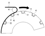
従来、熱硬化性CFRPのスキンとストリンガーを一体化させる方法として、図10に示すように、円筒状のマンドレル41の表面に形成された溝45の内部に複数のストリンガー31を設置しておき、その上からスキン32を積層しローラ42によって押圧することで一体化する方法がある。
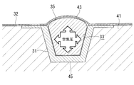
この方法において、一体化されたスキン32とストリンガー31によって筒状に形成される筒状部35の内部に中空の空間(中空部33)が形成される場合、ローラ42による押圧時に、中空部33に対応した部分に凹状の変形が生じないように、中空部33にブラダー43や中子を挿入しておく。例えば、下記の特許文献1~4には、中空部にブラダーが挿入される例が開示されている。
ブラダーは、ビニール製又はゴム製などの柔らかく伸縮性のある素材でできており、空気等の注入により膨らませることで、断面形状を変化させることができる。中子は、剛性が十分に高い素材でできている。
中空部にブラダーが挿入されると、ブラダーが柔軟に変形可能な素材であるため、ローラによる押圧時、場所ごとに筒状部の内周面の形状を調整することが難しい。
熱可塑性樹脂を用いたCFRPを成形する場合、合成樹脂と繊維を馴染ませるために、積層時、熱硬化性樹脂を用いた場合と比べて非常に高い圧力でローラによって材料を押圧する必要がある。熱可塑性樹脂の場合、積層時に必要な圧力が最大で20気圧程度となることがある。
熱硬化性CFRPと同様に、上述したマンドレルを用いた方法で、熱可塑性CFRPのスキンとストリンガーを一体化する場合、ローラによって高い圧力でスキンとストリンガーを押圧するため、熱硬化性の場合よりも筒状部の内周面に対応した部分がより変形しやすくなる。凹状の変形が生じないように、ブラダー内部を高圧にすると、図11に示すように、ブラダー43が膨らみすぎてしまい、製品の規定面からスキン32の位置が逸脱する可能性が高い。
中子を用いる場合、一体化されたスキンとストリンガーの間の中空部から中子を取り出す脱型作業が必要である。しかし、中空部からの中子の脱型は難しく、時間や手間が多くかかるという問題がある。また、ストリンガーの長手方向が直線状又は一定曲率の形状でない限り、中子の脱型が不可能である。
本開示は、このような事情に鑑みてなされたものであって、一方向に沿って長い材料の内部の形状を所定の形状に画定することができ、成形後に内部から容易に取り出すことが可能な治具を提供することを目的とする。
上記課題を解決するために、本開示の治具は以下の手段を採用する。
すなわち、本開示に係る治具は、被成形材料の筒状部の内周面に囲まれて一方向に形成された中空部に挿入される治具であって、前記内周面に対応した形状の接触面を有し、前記一方向に対して交差する方向に並列して配設された複数の型部と、前記型部に対して前記型部の前記接触面とは反対側に設置され、内部に流動体を収容でき、収容された前記流動体の圧力に応じて伸縮可能なブラダーと、前記複数の型部と前記ブラダーを接続する接続部と、前記複数の型部のうち一側の型部と、前記一側の型部に隣接する他側の型部を連結し、前記一方向に対して交差する方向における前記一側の型部と前記他側の型部の間隔を所定範囲内に規制する連結部とを備える。
すなわち、本開示に係る治具は、被成形材料の筒状部の内周面に囲まれて一方向に形成された中空部に挿入される治具であって、前記内周面に対応した形状の接触面を有し、前記一方向に対して交差する方向に並列して配設された複数の型部と、前記型部に対して前記型部の前記接触面とは反対側に設置され、内部に流動体を収容でき、収容された前記流動体の圧力に応じて伸縮可能なブラダーと、前記複数の型部と前記ブラダーを接続する接続部と、前記複数の型部のうち一側の型部と、前記一側の型部に隣接する他側の型部を連結し、前記一方向に対して交差する方向における前記一側の型部と前記他側の型部の間隔を所定範囲内に規制する連結部とを備える。
本開示によれば、一方向に沿って長い材料の内部の形状を所定の形状に画定することができ、成形後に内部から容易に取り出すことができる。
以下に、本開示に係る実施形態について、図面を参照して説明する。
本開示の一実施形態に係る治具1は、複合材、例えば炭素繊維強化プラスチック(CFRP)からなるスキンとストリンガーを一体化させる際に、スキンとストリンガーの間に形成される中空部に配置される。中空部は、スキンとストリンガーによって筒状に形成される筒状部の内周面に囲まれて一方向に形成される。スキンとストリンガーは、被成形材料の一例である。
本開示の一実施形態に係る治具1は、複合材、例えば炭素繊維強化プラスチック(CFRP)からなるスキンとストリンガーを一体化させる際に、スキンとストリンガーの間に形成される中空部に配置される。中空部は、スキンとストリンガーによって筒状に形成される筒状部の内周面に囲まれて一方向に形成される。スキンとストリンガーは、被成形材料の一例である。
複合材の成形装置は、図5に示すように、マンドレル41とローラ42を備える。円筒状のマンドレル41の表面に形成された溝45の内部に複数のストリンガー31を設置しておき、その上からスキン32を積層しローラ42によって押圧する方法において、中空部33に対応した部分に凹状の変形が生じないように、中空部33に本実施形態に係る治具1が配置される。熱硬化性CFRPのスキン32とストリンガー31を一体化させる際、一体化されたスキン32とストリンガー31によって筒状に形成される筒状部35(図4参照)の内部に中空の空間(中空部33)が形成されるため、ローラ42による押圧時に、中空部33に対応した部分に凹状の変形が生じないように、中空部33に治具1が挿入される。
スキン32は、例えば航空機の胴体を構成する円弧状の断面を有する板状部材である。ストリンガー31は、一方向沿って長い長尺状部材であり、断面形状がハット型、Z型などを有する。以下では、ストリンガー31の断面がハット型を有する場合について説明するが、本開示はこの例に限定されない。スキン32とストリンガー31が一体的に成形されることによって、航空機構造が構成される。
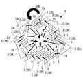
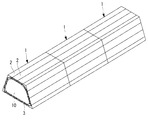
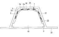
本実施形態に係る治具1は、図1~図4に示すように、複数の型部2と、ブラダー3、接続部4と、連結部5などを備える。
複数の型部2は、一方向に沿って長い長尺状の部品である。複数の型部2はそれぞれ、図4に示すように、スキン32とストリンガー31によって筒状に形成される筒状部35の内周面34に対応した形状の接触面2aを有する。これにより、スキン32とストリンガー31が一体的に成形されて航空機部品(例えば胴体)が形成される際、複数の型部2の接触面2aによって筒状部35の内周面34の形状を画定できる。
複数の型部2は、中空部33が延設された長手方向に対して交差する方向に並列して配設される。複数の型部2は、図1及び図2に示すように、断面が環状となるように連結部5を介して互いに連結されている。これにより、図4に示すように、ブラダー3が膨らんだとき、内周面34の全てにわたって複数の型部2の接触面2aが接触する。
型部2は、ブラダー3よりも剛性が高い素材であり、例えば、アルミニウム合金などの金属材料、合成樹脂材料などである。
図1に示すように、型部2は、内周面34の隅部に対応して配置されるコーナ部品2Aと、二つのコーナ部品2Aの間であって、内周面34の平面部に対応して配置される平面部品2Bとを有する。コーナ部品2Aは、例えば、断面が三角形の一つの頂点を欠いた四角形形状を有する。平面部品2Bは、例えば断面が平行四辺形形状を有する。
型部2の長手方向は、形成するストリンガー31の長さと同等の長さを有してもよいし、または、図3に示すように、治具1は、ストリンガー31の長手方向において複数に分割されて中空部33に配置されてもよい。これにより、ストリンガー31が長手方向において湾曲している場合でも、治具1を中空部33に配置できる。
ブラダー3は、例えば、ビニール製又はゴム製などの柔らかく伸縮性のある素材であり、内部に流動体10を収容できる袋状の部材である。ブラダー3の内部に収容される流動体10は、例えば、流体(例えば空気、液体など)又は粉体である。ブラダー3は、環状の複数の型部2の内部、すなわち、各型部2に対して、内周面34と接する型部2の接触面2a側とは反対側に設置される。ブラダー3は、収容された流動体10の圧力(例えば空気圧、液圧、粉体圧など)に応じて伸縮可能である。ブラダー3は、型部2の長手方向にわたって設けられる。
接続部4は、例えばブラダー3と同一の素材、ビニール製又はゴム製などの柔らかく伸縮性のある素材であり、複数の型部2とブラダー3を接続する。接続部4は、型部2ごとに一つずつ設けられ、一端が型部2と接続され、他端がブラダー3と接続される。
連結部5は、型部2の長手方向端部に設置される棒(バー)状部品である。連結部5は、互いに隣接して配置された二つの型部2同士を連結する。すなわち、連結部5は、複数の型部2のうち一側の型部2と、一側の型部2に隣接する他側の型部2を連結し、一側の型部2と他側の型部2の間隔を所定範囲内に規制する。
型部2の長手方向端部の端面には、連結部5が接続される固定部6とスライド溝7が形成されている。固定部6は、例えば円形状の孔であり、型部2の幅方向端部2b(一端部)に設けられる。ここで、型部2の幅方向とは、型部2の長手方向に対して交差する方向であり、中空部33に沿って型部2が配置されたとき、内周面34に沿った方向である。型部2の固定部6において、連結部5の一端が回動可能に接続される。
また、スライド溝7は、例えば、図1に示すように、一端7aから他端7bにわたって設けられた一方向に長い溝であり、型部2の長手方向端部の端面において、固定部6の近傍の一端7aから、固定部6が設けられた端部2bとは反対側の幅方向端部2c近傍の他端7bにわたって、型部2の接触面2aに沿う方向に形成される。型部2のスライド溝7において、連結部5の他端が型部2の端面において接触面2aに沿う方向に移動可能に接続される。
ブラダー3が膨張すると、連結部5の他端がスライド溝7の他端7b側に移動する。連結部5の長さは、ブラダー3が膨張したときの一側の型部2の固定部6と、他側の型部2のスライド溝7の他端7bとの間の距離と等しいか、又は、隣り合う型部2同士が摺動可能な程度にわずかに長い。これにより、ブラダー3が膨張したとき、一側の型部2と他側の型部2の間隔が所定範囲内に規制される。
型部2のうち平面部品2Bが有する平行四辺形の断面において、接触面2aとは反対側のブラダー3が設けられた側に設けられた頂点は、固定部6側、すなわち端部2b側が鈍角であり、固定部6とは反対側の幅方向端部2c側が鋭角である。
ブラダー3と接続された接続部4は、図2に示すように、連結部5の一端が接続された型部2の固定部6とは反対側の幅方向端部2c(他端部)において、型部2と接続される。接続部4が型部2の図心とは異なる位置で接続されているため、ブラダー3がしぼむとき、型部2は回転しながら内側に引き込まれる。
以上、本実施形態によれば、複数の型部2は、内周面34に対応した形状の接触面2aを有することから、航空機胴体などの成形品が形成される際、複数の型部2の接触面2aによって内周面34の形状を画定できる。ブラダー3の内部に流動体10が収容されると、流動体10の圧力に応じてブラダー3が伸張し膨らむ。膨らんだブラダー3は、型部2に対して型部2の接触面2aとは反対側、すなわち、環状の複数の型部2の内部側から複数の型部2を押圧する。連結部5は、複数の型部2のうち一側の型部2と他側の型部2の間隔を所定範囲内に規制することから、ブラダー3の押圧力によって複数の型部2間の間隔が広がりすぎることがない。その結果、ブラダー3の膨らみ量を所定範囲内に抑制できるため、ブラダー3の膨らみすぎを防止できる。
他方、ブラダー3の内部から流動体10が排出されると、流動体10の圧力に応じてブラダー3が収縮ししぼむ。しぼんだブラダー3は、複数の型部2とブラダー3を接続する接続部4を介して、複数の型部2を、型部2に対して型部2の接触面2aとは反対側のブラダー3側に引き寄せる。その結果、複数の型部2の接触面2aが内周面34から離れて、外形が中空部33よりも小さくなるため、治具1を中空部33から容易に取り外すことができる。
型部2同士を連結する連結部5の一端が一側の型部2の端部2bにおいて回動可能に接続されていることから、互いに隣接する一側の型部2と他側の型部2の位置が変化すると、連結部5の一端を中心にして連結部5が回動する。また、連結部5の他端が他側の型部2において、型部2の幅方向に沿って移動可能に接続されていることから、互いに隣接する一側の型部2と他側の型部2の位置が変化すると、連結部5の他端が他側の型部2の幅方向に沿って移動する。ブラダー3が膨らんだとき、連結部5の他端は他側の型部2の端部2c側に移動し、ブラダー3がしぼんだとき、連結部5の他端は他側の型部2の中間部側に向けて移動する。
型部2とブラダー3を接続する接続部4は、連結部5の一端が接続された一側の型部2の端部2bとは反対の端部2cに接続される。これにより、接続部4が型部2の図心とは異なる位置で接続されているため、ブラダー3がしぼむとき、型部2は回転しながら内側に引き込まれる。
次に、ストリンガーとスキンを成形する際の本実施形態に係る治具1の使用方法について説明する。
まず、断面が円弧状を有するマンドレル41の表面に形成された溝45の内部に、ストリンガー31が設置される。
そして、ストリンガー31の内部、すなわち、スキン32とストリンガー31の間で中空部33となる部分に、本実施形態に係る治具1が設置される。このとき、治具1が挿入可能な程度にブラダー3を膨らませ、複数の型部2の接触面2aをスキン32とストリンガー31の間に形成される内周面34に沿わせることが可能なようにしておくことが望ましい。
治具1が設置された後、スキン32をストリンガー31又は治具1の上に積層する。このとき、例えばローラ42を用いて、スキン32とストリンガー31を押圧しながらスキン32を積層していく。したがって、ローラ42による押圧前に、ローラ42による押圧力に耐えうるように、ブラダー3の内部圧力を上昇させておく。また、ローラ42を用いた積層工程において、剛性の高い型部2は変形しにくいため、内周面34の形状を画定できる。
次に、ストリンガー31に対するスキン32の積層作業が完了し、ストリンガー31とスキン32が一体化した後、ブラダー3の内部圧力を低下させて、ブラダー3をしぼませる。そして、治具1の接触面2aが内周面34から離れた後、治具1を中空部33から取り外すことができる。
上述した実施形態では、複数の型部2が連結部5によって連結されて断面が環状となる場合について説明したが、本発明はこの例に限定されない。
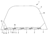
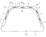
複数の型部2は、例えば図6及び図8に示すように、両側に配設された型部2が自由端となるように連結部5を介して互いに連結されてもよい。すなわち、両側に配設された型部2の片側は、他の型部2に連結されず、自由端となる。この場合、図7及び図9に示すように、ブラダー3が膨らんだとき、内周面34の一部において複数の型部2の接触面2aが接触する。
例えば、図7に示すように、図6に示した治具1が中空部33に配置されたとき、スキン32側のみに型部2が接するように、ブラダー3に対して一方のみに複数の型部2が設置されてもよい。この場合、内周面34において、スキン32側の形状を画定できる。また、図9に示すように、図7に示した治具1が中空部33に配置されたとき、ストリンガー31側のみに型部2が接するように、ブラダー3に対して一方のみに複数の型部2が設置されてもよい。この場合、内周面34において、ストリンガー31側の形状を画定できる。
本開示に係る治具1は、熱硬化性樹脂を用いた炭素繊維強化プラスチック(CFRP)の成形品を形成する場合と、熱可塑性樹脂を用いたCFRPの成形品を形成する場合のいずれにおいても適用可能である。特に、熱可塑性樹脂を用いたCFRPを成形するため、積層時、熱硬化性樹脂を用いた場合と比べて非常に高い圧力でローラ42によって材料を押圧する場合であっても、規定の形状以上に膨らむことを防止することで、スキン32とストリンガー31の間の内周面34の形状を画定できる。また、ブラダー3をしぼませることによって、中空部33から治具1を容易に取り外すことができる。
以上説明した実施形態に記載の治具は例えば以下のように把握される。
本開示に係る治具(1)は、被成形材料の筒状部(35)の内周面(34)に囲まれて一方向に形成された中空部(33)に挿入される治具であって、前記内周面に対応した形状の接触面(2a)を有し、前記一方向に対して交差する方向に並列して配設された複数の型部(2)と、前記型部に対して前記複数の型部の前記接触面とは反対側に設置され、内部に流動体(10)を収容でき、収容された前記流動体の圧力に応じて伸縮可能なブラダー(3)と、前記複数の型部と前記ブラダーを接続する接続部(4)と、前記複数の型部のうち一側の型部と、前記一側の型部に隣接する他側の型部を連結し、前記一方向に対して交差する方向における前記一側の型部と前記他側の型部の間隔を所定範囲内に規制する連結部(5)とを備える。
本開示に係る治具(1)は、被成形材料の筒状部(35)の内周面(34)に囲まれて一方向に形成された中空部(33)に挿入される治具であって、前記内周面に対応した形状の接触面(2a)を有し、前記一方向に対して交差する方向に並列して配設された複数の型部(2)と、前記型部に対して前記複数の型部の前記接触面とは反対側に設置され、内部に流動体(10)を収容でき、収容された前記流動体の圧力に応じて伸縮可能なブラダー(3)と、前記複数の型部と前記ブラダーを接続する接続部(4)と、前記複数の型部のうち一側の型部と、前記一側の型部に隣接する他側の型部を連結し、前記一方向に対して交差する方向における前記一側の型部と前記他側の型部の間隔を所定範囲内に規制する連結部(5)とを備える。
この構成によれば、複数の型部は、内周面に対応した形状の接触面を有することから、成形品が形成される際、複数の型部の接触面によって内周面の形状を画定できる。ブラダーの内部に流動体が収容されると、流動体の圧力に応じてブラダーが伸張し膨らむ。膨らんだブラダーは、型部に対して型部の接触面とは反対側から複数の型部を押圧する。連結部は、複数の部品のうち一側の型部と他側の型部の間隔を所定範囲内に規制することから、ブラダーの押圧力によって複数の型部間の間隔が広がりすぎることがない。その結果、ブラダーの膨らみ量を所定範囲内に抑制できるため、ブラダーの膨らみすぎを防止できる。
他方、ブラダーの内部から流動体が排出されると、流動体の圧力に応じてブラダーが収縮ししぼむ。しぼんだブラダーは、複数の型部とブラダーを接続する接続部を介して、複数の型部を、型部に対して型部の接触面とは反対側のブラダー側に引き寄せる。その結果、複数の型部の接触面が内周面から離れて、外形が中空部よりも小さくなるため、治具を中空部から容易に取り外すことができる。
本開示に係る治具において、前記複数の型部は、前記一方向に対して交差する方向に切断した断面が環状となるように前記連結部を介して互いに連結されてもよい。
この構成によれば、ブラダーが膨らんだとき、内周面の全てにわたって複数の型部の接触面が接触する。
本開示に係る治具において、前記複数の型部は、両側に配設された前記型部が自由端となるように前記連結部を介して互いに連結されてもよい。
この構成によれば、並列して配設された複数の型部のうち両側に配設された型部の片側は、他の前記型部に連結されず、自由端となるように連結部を介して互いに連結される。この場合、ブラダーが膨らんだとき、内周面の一部において複数の型部の接触面が接触する。
本開示に係る治具において、前記連結部は、棒状部材であり、一端が前記一側の型部の端面において設けられた固定部(6)にて回動可能に接続され、他端が前記他側の型部の端面において設けられたスライド溝(7)にて前記接触面に沿う方向に移動可能に接続されてもよい。
この構成によれば、連結部の一端が一側の型部の端面において設けられた固定部にて回動可能に接続されていることから、互いに隣接する一側の型部と他側の型部の位置が変化すると、連結部の一端を中心にして連結部が回動する。また、連結部の他端が他側の型部の端面において設けられたスライド溝にて、幅方向に沿って移動可能に接続されていることから、互いに隣接する一側の型部と他側の型部の位置が変化すると、連結部の他端が他側の型部の幅方向に沿って移動する。ブラダーが膨らんだとき、連結部の他端は他側の型部の端部側に移動し、ブラダーがしぼんだとき、連結部の他端は他側の型部の中間部側に向けて移動する。
本開示に係る治具において、前記連結部の長さは、前記ブラダーが膨張したときの前記一側の型部の前記固定部と、前記他側の型部の前記スライド溝のうち前記固定部が設けられた端部とは反対側の幅方向端部側の端部との間の距離と等しくてもよい。
この構成によれば、ブラダーが膨張したとき、一側の型部と他側の型部の間隔が所定範囲内に規制される。
本開示に係る治具において、前記接続部は、前記連結部の一端が接続された前記一側の型部の一端部とは反対の他端部に接続されてもよい。
この構成によれば、接続部が一側の型部の図心とは異なる位置で接続されているため、ブラダーがしぼむとき、一側の型部は回転しながら内側に引き込まれる。
本開示に係る治具は、前記被成形材料の前記中空部の長手方向において複数に分割されて配置されてもよい。
この構成によれば、被成形材料が長手方向において湾曲している場合でも、治具を中空部に配置できる。
1 :治具
2 :型部
2A :コーナ部品
2B :平面部品
2a :接触面
2b,2c:端部
3 :ブラダー
4 :接続部
5 :連結部
6 :固定部
7 :スライド溝
10 :流動体
31 :ストリンガー
32 :スキン
33 :中空部
34 :内周面
35 :筒状部
41 :マンドレル
42 :ローラ
43 :ブラダー
45 :溝
2 :型部
2A :コーナ部品
2B :平面部品
2a :接触面
2b,2c:端部
3 :ブラダー
4 :接続部
5 :連結部
6 :固定部
7 :スライド溝
10 :流動体
31 :ストリンガー
32 :スキン
33 :中空部
34 :内周面
35 :筒状部
41 :マンドレル
42 :ローラ
43 :ブラダー
45 :溝
Claims (7)
- 被成形材料の筒状部の内周面に囲まれて一方向に形成された中空部に挿入される治具であって、
前記内周面に対応した形状の接触面を有し、前記一方向に対して交差する方向に並列して配設された複数の型部と、
前記型部に対して前記型部の前記接触面とは反対側に設置され、内部に流動体を収容でき、収容された前記流動体の圧力に応じて伸縮可能なブラダーと、
前記複数の型部と前記ブラダーを接続する接続部と、
前記複数の型部のうち一側の型部と、前記一側の型部に隣接する他側の型部を連結し、前記一方向に対して交差する方向における前記一側の型部と前記他側の型部の間隔を所定範囲内に規制する連結部と、
を備える治具。 - 前記複数の型部は、前記一方向に対して交差する方向に切断した断面が環状となるように前記連結部を介して互いに連結されている請求項1に記載の治具。
- 前記複数の型部は、両側に配設された前記型部が自由端となるように前記連結部を介して互いに連結されている請求項1に記載の治具。
- 前記連結部は、棒状部材であり、一端が前記一側の型部の端面において設けられた固定部にて回動可能に接続され、他端が前記他側の型部の端面において設けられたスライド溝にて前記接触面に沿う方向に移動可能に接続されている請求項1から3のいずれか1項に記載の治具。
- 前記連結部の長さは、前記ブラダーが膨張したときの前記一側の型部の前記固定部と、前記他側の型部の前記スライド溝のうち前記固定部が設けられた端部とは反対側の幅方向端部側の端部との間の距離と等しい請求項4に記載の治具。
- 前記接続部は、前記連結部の一端が接続された前記一側の型部の一端部とは反対の他端部に接続される請求項1から5のいずれか1項に記載の治具。
- 前記被成形材料の前記中空部の長手方向において複数に分割されて配置される請求項1から6のいずれか1項に記載の治具。
Priority Applications (4)
| Application Number | Priority Date | Filing Date | Title |
|---|---|---|---|
| US17/635,821 US11931926B2 (en) | 2019-11-14 | 2019-11-14 | Jig |
| EP19952452.1A EP3998145B1 (en) | 2019-11-14 | 2019-11-14 | Jig |
| JP2021555724A JP7180011B2 (ja) | 2019-11-14 | 2019-11-14 | 治具 |
| PCT/JP2019/044740 WO2021095207A1 (ja) | 2019-11-14 | 2019-11-14 | 治具 |
Applications Claiming Priority (1)
| Application Number | Priority Date | Filing Date | Title |
|---|---|---|---|
| PCT/JP2019/044740 WO2021095207A1 (ja) | 2019-11-14 | 2019-11-14 | 治具 |
Publications (1)
| Publication Number | Publication Date |
|---|---|
| WO2021095207A1 true WO2021095207A1 (ja) | 2021-05-20 |
Family
ID=75912579
Family Applications (1)
| Application Number | Title | Priority Date | Filing Date |
|---|---|---|---|
| PCT/JP2019/044740 Ceased WO2021095207A1 (ja) | 2019-11-14 | 2019-11-14 | 治具 |
Country Status (4)
| Country | Link |
|---|---|
| US (1) | US11931926B2 (ja) |
| EP (1) | EP3998145B1 (ja) |
| JP (1) | JP7180011B2 (ja) |
| WO (1) | WO2021095207A1 (ja) |
Cited By (2)
| Publication number | Priority date | Publication date | Assignee | Title |
|---|---|---|---|---|
| CN114572575A (zh) * | 2022-01-24 | 2022-06-03 | 昆明中天达玻璃钢开发有限公司 | 一种双层储罐及储罐加工装置及双层储罐的加工方法 |
| JP2023170330A (ja) * | 2022-05-19 | 2023-12-01 | トヨタ自動車株式会社 | 複合材中空部品の成形方法、及び、中空部品成形システム |
Families Citing this family (1)
| Publication number | Priority date | Publication date | Assignee | Title |
|---|---|---|---|---|
| JPWO2023095424A1 (ja) * | 2021-11-29 | 2023-06-01 |
Citations (5)
| Publication number | Priority date | Publication date | Assignee | Title |
|---|---|---|---|---|
| JP2009542460A (ja) * | 2006-07-06 | 2009-12-03 | エアバス・オペレーションズ・ゲーエムベーハー | 折り畳み可能な成形コアを用いた複合ファイバ構成要素を作製する方法および上記成形コア |
| JP2011235635A (ja) * | 2010-05-11 | 2011-11-24 | Boeing Co:The | 強化フルオロエラストマーブラダを用いた折り畳み式マンドレル |
| US8293051B2 (en) | 2008-12-10 | 2012-10-23 | The Boeing Company | Method for producing composite laminates using a collapsible mandrel |
| US9296187B2 (en) | 2008-12-10 | 2016-03-29 | The Boeing Company | Bagging process and mandrel for fabrication of elongated composite structure |
| US10059041B2 (en) | 2015-08-10 | 2018-08-28 | The Boeing Company | Multi-state bladder for manufacture of composite material |
-
2019
- 2019-11-14 EP EP19952452.1A patent/EP3998145B1/en active Active
- 2019-11-14 JP JP2021555724A patent/JP7180011B2/ja active Active
- 2019-11-14 WO PCT/JP2019/044740 patent/WO2021095207A1/ja not_active Ceased
- 2019-11-14 US US17/635,821 patent/US11931926B2/en active Active
Patent Citations (6)
| Publication number | Priority date | Publication date | Assignee | Title |
|---|---|---|---|---|
| JP2009542460A (ja) * | 2006-07-06 | 2009-12-03 | エアバス・オペレーションズ・ゲーエムベーハー | 折り畳み可能な成形コアを用いた複合ファイバ構成要素を作製する方法および上記成形コア |
| US8500085B2 (en) | 2006-07-06 | 2013-08-06 | Airbus Operations Gmbh | Method for manufacturing a composite fiber component for aerospace |
| US8293051B2 (en) | 2008-12-10 | 2012-10-23 | The Boeing Company | Method for producing composite laminates using a collapsible mandrel |
| US9296187B2 (en) | 2008-12-10 | 2016-03-29 | The Boeing Company | Bagging process and mandrel for fabrication of elongated composite structure |
| JP2011235635A (ja) * | 2010-05-11 | 2011-11-24 | Boeing Co:The | 強化フルオロエラストマーブラダを用いた折り畳み式マンドレル |
| US10059041B2 (en) | 2015-08-10 | 2018-08-28 | The Boeing Company | Multi-state bladder for manufacture of composite material |
Non-Patent Citations (1)
| Title |
|---|
| See also references of EP3998145A4 |
Cited By (4)
| Publication number | Priority date | Publication date | Assignee | Title |
|---|---|---|---|---|
| CN114572575A (zh) * | 2022-01-24 | 2022-06-03 | 昆明中天达玻璃钢开发有限公司 | 一种双层储罐及储罐加工装置及双层储罐的加工方法 |
| CN114572575B (zh) * | 2022-01-24 | 2024-03-12 | 昆明中天达玻璃钢开发有限公司 | 一种储罐加工装置及双层储罐的加工方法 |
| JP2023170330A (ja) * | 2022-05-19 | 2023-12-01 | トヨタ自動車株式会社 | 複合材中空部品の成形方法、及び、中空部品成形システム |
| JP7643395B2 (ja) | 2022-05-19 | 2025-03-11 | トヨタ自動車株式会社 | 複合材中空部品の成形方法 |
Also Published As
| Publication number | Publication date |
|---|---|
| JP7180011B2 (ja) | 2022-11-29 |
| JPWO2021095207A1 (ja) | 2021-05-20 |
| EP3998145A4 (en) | 2022-09-07 |
| US20220305699A1 (en) | 2022-09-29 |
| EP3998145B1 (en) | 2024-01-24 |
| US11931926B2 (en) | 2024-03-19 |
| EP3998145A1 (en) | 2022-05-18 |
Similar Documents
| Publication | Publication Date | Title |
|---|---|---|
| ES2357780T3 (es) | Método y aparato para formar elementos estructurales. | |
| CN103180123B (zh) | 用于借助形状记忆聚合物设备来形成一体式复合部件的方法和系统 | |
| US10286577B2 (en) | Composite mandrel for autoclave curing applications | |
| US8430984B2 (en) | Collapsible mandrel employing reinforced fluoroelastomeric bladder | |
| US9724848B2 (en) | Collapsible, coiled mandrel | |
| EP1943087B1 (en) | Expandible compaction tool and method for manufacturing composite structures | |
| JP7180011B2 (ja) | 治具 | |
| CN103180116B (zh) | 用于用刚性/可延展形状记忆聚合物设备来使复合部件共粘结或共固化的方法和系统 | |
| CA2673975C (en) | Helicopter blade mandrel | |
| US9694898B2 (en) | Methods for manufacturing an I-stringer of an aircraft and devices for use in such methods | |
| US4698011A (en) | Manufacture of a hollow envelope by winding filamentary material | |
| US10744724B2 (en) | Composite aircraft manufacturing tooling and methods using articulating mandrels | |
| FR2981002A1 (fr) | Procede de realisation d'un panneau raidi extrude et dispositif de mise en oeuvre | |
| US20170100859A1 (en) | Mechanical Support Tooling and/or Mandrel for Composite Part Curing | |
| CN108340594B (zh) | 用于复合部件的心轴及用心轴修补和形成部件的方法 | |
| US9724870B2 (en) | Integrated shape memory polymer and caul tool | |
| JP2007301865A (ja) | ハニカムコア成形シートの製造方法、金型 | |
| WO2015033625A1 (ja) | 中子型および中空構造体の製造方法 | |
| CN114506095A (zh) | 一种用于制作帽型增强构件的芯模 | |
| JP5325703B2 (ja) | ビード部材の製造方法及び製造装置 | |
| CA2964403C (en) | Sports shaft with stiffening bumper | |
| JPH031229Y2 (ja) | ||
| JP2009000971A (ja) | 安全タイヤ用空気のうを製造する装置及び方法 | |
| CZ28039U1 (cs) | Nafukovací lisovací trn k výrobě vláknového kompozitového profil |
Legal Events
| Date | Code | Title | Description |
|---|---|---|---|
| 121 | Ep: the epo has been informed by wipo that ep was designated in this application |
Ref document number: 19952452 Country of ref document: EP Kind code of ref document: A1 |
|
| WWE | Wipo information: entry into national phase |
Ref document number: 2021555724 Country of ref document: JP |
|
| ENP | Entry into the national phase |
Ref document number: 2019952452 Country of ref document: EP Effective date: 20220210 |
|
| NENP | Non-entry into the national phase |
Ref country code: DE |