WO2021095559A1 - Terminal de communication sans fil et procédé - Google Patents
Terminal de communication sans fil et procédé Download PDFInfo
- Publication number
- WO2021095559A1 WO2021095559A1 PCT/JP2020/040769 JP2020040769W WO2021095559A1 WO 2021095559 A1 WO2021095559 A1 WO 2021095559A1 JP 2020040769 W JP2020040769 W JP 2020040769W WO 2021095559 A1 WO2021095559 A1 WO 2021095559A1
- Authority
- WO
- WIPO (PCT)
- Prior art keywords
- wireless communication
- cooperative transmission
- control unit
- transmission
- reception
- Prior art date
- Legal status (The legal status is an assumption and is not a legal conclusion. Google has not performed a legal analysis and makes no representation as to the accuracy of the status listed.)
- Ceased
Links
Images









Classifications
-
- H—ELECTRICITY
- H04—ELECTRIC COMMUNICATION TECHNIQUE
- H04W—WIRELESS COMMUNICATION NETWORKS
- H04W16/00—Network planning, e.g. coverage or traffic planning tools; Network deployment, e.g. resource partitioning or cells structures
- H04W16/14—Spectrum sharing arrangements between different networks
-
- H—ELECTRICITY
- H04—ELECTRIC COMMUNICATION TECHNIQUE
- H04W—WIRELESS COMMUNICATION NETWORKS
- H04W48/00—Access restriction; Network selection; Access point selection
- H04W48/18—Selecting a network or a communication service
-
- H—ELECTRICITY
- H04—ELECTRIC COMMUNICATION TECHNIQUE
- H04W—WIRELESS COMMUNICATION NETWORKS
- H04W28/00—Network traffic management; Network resource management
- H04W28/02—Traffic management, e.g. flow control or congestion control
- H04W28/0231—Traffic management, e.g. flow control or congestion control based on communication conditions
- H04W28/0236—Traffic management, e.g. flow control or congestion control based on communication conditions radio quality, e.g. interference, losses or delay
-
- H—ELECTRICITY
- H04—ELECTRIC COMMUNICATION TECHNIQUE
- H04W—WIRELESS COMMUNICATION NETWORKS
- H04W40/00—Communication routing or communication path finding
- H04W40/02—Communication route or path selection, e.g. power-based or shortest path routing
- H04W40/22—Communication route or path selection, e.g. power-based or shortest path routing using selective relaying for reaching a BTS [Base Transceiver Station] or an access point
-
- H—ELECTRICITY
- H04—ELECTRIC COMMUNICATION TECHNIQUE
- H04W—WIRELESS COMMUNICATION NETWORKS
- H04W48/00—Access restriction; Network selection; Access point selection
- H04W48/16—Discovering, processing access restriction or access information
-
- H—ELECTRICITY
- H04—ELECTRIC COMMUNICATION TECHNIQUE
- H04W—WIRELESS COMMUNICATION NETWORKS
- H04W76/00—Connection management
- H04W76/10—Connection setup
- H04W76/15—Setup of multiple wireless link connections
-
- H—ELECTRICITY
- H04—ELECTRIC COMMUNICATION TECHNIQUE
- H04B—TRANSMISSION
- H04B7/00—Radio transmission systems, i.e. using radiation field
- H04B7/02—Diversity systems; Multi-antenna system, i.e. transmission or reception using multiple antennas
- H04B7/022—Site diversity; Macro-diversity
- H04B7/024—Co-operative use of antennas of several sites, e.g. in co-ordinated multipoint or co-operative multiple-input multiple-output [MIMO] systems
-
- H—ELECTRICITY
- H04—ELECTRIC COMMUNICATION TECHNIQUE
- H04L—TRANSMISSION OF DIGITAL INFORMATION, e.g. TELEGRAPHIC COMMUNICATION
- H04L1/00—Arrangements for detecting or preventing errors in the information received
- H04L1/12—Arrangements for detecting or preventing errors in the information received by using return channel
- H04L1/16—Arrangements for detecting or preventing errors in the information received by using return channel in which the return channel carries supervisory signals, e.g. repetition request signals
- H04L1/18—Automatic repetition systems, e.g. Van Duuren systems
- H04L1/1867—Arrangements specially adapted for the transmitter end
- H04L1/1896—ARQ related signaling
-
- H—ELECTRICITY
- H04—ELECTRIC COMMUNICATION TECHNIQUE
- H04L—TRANSMISSION OF DIGITAL INFORMATION, e.g. TELEGRAPHIC COMMUNICATION
- H04L1/00—Arrangements for detecting or preventing errors in the information received
- H04L2001/0092—Error control systems characterised by the topology of the transmission link
- H04L2001/0093—Point-to-multipoint
-
- H—ELECTRICITY
- H04—ELECTRIC COMMUNICATION TECHNIQUE
- H04W—WIRELESS COMMUNICATION NETWORKS
- H04W48/00—Access restriction; Network selection; Access point selection
- H04W48/20—Selecting an access point
-
- H—ELECTRICITY
- H04—ELECTRIC COMMUNICATION TECHNIQUE
- H04W—WIRELESS COMMUNICATION NETWORKS
- H04W84/00—Network topologies
- H04W84/02—Hierarchically pre-organised networks, e.g. paging networks, cellular networks, WLAN [Wireless Local Area Network] or WLL [Wireless Local Loop]
- H04W84/10—Small scale networks; Flat hierarchical networks
- H04W84/12—WLAN [Wireless Local Area Networks]
Definitions
- the present technology relates to wireless communication terminals and methods, and more particularly to wireless communication terminals and methods that enable cooperative transmission to be executed via a desired access point.
- Patent Document 1 discloses a technique for connecting a mobile phone to a wireless LAN.
- the content data can only be acquired via the only AP with which the association was made, so it was difficult to view satisfactory content in an environment where the connection with this AP was unstable.
- the receiving communication terminal can more reliably transmit the content data. Can be received.
- This technology was made in view of such a situation, and enables cooperative transmission to be executed via a desired access point.
- the wireless communication terminal on one aspect of the present technology includes a communication control unit that starts the setup of the cooperative transmission in order to execute the cooperative transmission in a plurality of wireless communication devices.
- the setup of the cooperative transmission is started in order to execute the cooperative transmission in a plurality of wireless communication devices.
- FIG. 23 is a flowchart for explaining the communication setting process of the user terminal following FIG. 23. It is a flowchart explaining the cooperative reception process of a user terminal. It is a flowchart explaining the cooperative reception process of a user terminal following FIG. It is a block diagram which shows the configuration example of a computer.
- FIG. 1 is a diagram showing a configuration example of a wireless communication system according to the first embodiment of the present technology.
- the wireless communication system of FIG. 1 is composed of a user terminal 11, AP1 to AP3, Provider1 and Provider2, and a data server 12.
- the user terminal 11 is composed of terminals capable of wireless communication such as smartphones, mobile phones, mobile terminals, and personal computers.
- the user terminal 11 exists at a position where it can be connected to AP1 to AP3 by wireless communication.
- the data server 12 is a server that stores content data.
- the data server 12 is connected to Provider 1 and Provider 2 via the Internet 13.
- AP1 to AP3 are access points to which the user terminal 11 can be connected, and are composed of wireless communication devices 14-1 to 14-3.
- AP1 and AP2 are connected to Provider1 by wireless communication or wired communication.
- AP3 is connected to Provider2 by wireless communication or wired communication.
- the wireless communication devices 14-1 to 14-3 will be referred to as a wireless communication device 14 when it is not necessary to distinguish them.
- Provider1 and Provider2 are service providers for the user terminal 11 to connect to the Internet 13.
- Provider1 and Provider2 are composed of communication devices 15-1 and 15-2.
- the communication devices 15-1 and 15-2 will be referred to as a communication device 15 when it is not necessary to distinguish them.
- the user terminal 11 By connecting to at least two APs of AP1 or AP2 connected to Provider1 or AP3 connected to Provider2, the user terminal 11 transfers the content data stored in the data server 12 via the plurality of APs. It is possible to receive by the coordinated transmission.
- the user terminal 11 starts the setup of cooperative transmission in order to cause a plurality of APs to execute cooperative transmission.
- the cooperative transmission setup is a process of exchanging information for setting which AP is used to execute the cooperative transmission as a preparation before executing the cooperative transmission.
- the cooperative transmission setup is started by making a cooperative transmission setup request.
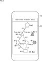
- FIG. 2 is a diagram showing an example of an AP / route setting screen in the user terminal 11.
- the display unit 31 of the user terminal 11 is shown.
- the display unit 31 displays the AP / route setting screen in the wireless communication system of FIG.
- the AP / route setting screen is configured so that the AP for cooperative transmission and the route from the data server 12 to the user terminal 11 can be selected in order to deliver the content data of the data server 12 to the user terminal 11. There is.
- icons M11, M12, M14-1 to M14-3, and M15-1 and M15-2 are displayed as information indicating the devices constituting the wireless communication system shown in FIG.
- the icon M11 is an icon indicating the user terminal 11.
- the icon M12 is an icon indicating the data server 12.
- the icons M14-1 to M14-3 are icons indicating AP1 to AP3, respectively.
- the icons M15-1 and M15-2 are icons indicating Provider1 and Provider2, respectively.
- the route L1 representing the data transmission route is indicated by a solid line.
- the route L2 is shown by a solid line between the icon M14-1 of AP1 and the icon M15-1 of Provider1.
- the route L5 is indicated by a solid line between the provider icon M15-1 and the data server 12 icon M12. The route shown by the solid line is the route currently connected.
- the route L3 is indicated by a broken line between the icon M11 of the user terminal 11 and the icon M14-2 of the AP2.
- the route L4 is indicated by a broken line between the icon M14-2 of AP2 and the icon M15-1 of Provider1.
- the AP / route setting screen in which AP2 and Provider1 are selected according to the user's instruction is shown, and AP2 is selected as the AP that can be co-transmitted with AP1 in the route shown by the broken line. Indicates that the route is selected in some cases.
- AP2 capable of cooperative transmission is displayed in a state of being selected by the user's instruction. Has been done.
- the numerical value (384 Mbps) at the bottom right of the AP / route setting screen shows the estimated maximum throughput when using the route selected by selecting the AP in addition to the route currently connected.
- the estimated speed at least one of the estimated speed of the route selected by selecting the AP and the estimated speed of the currently connected route may be displayed.
- information related to the communication status and the communication status may be displayed.
- multiple APs capable of cooperative transmission and the route and communication status selected by selecting the AP are displayed in sequence. Therefore, the user can select a plurality of APs that execute cooperative transmission and a route to the data server 12 according to the communication status.
- FIG. 3 is a diagram showing a communication sequence of the present technology.
- FIG. 3 shows the flow of signals exchanged between the user terminals 11, AP1 to AP3, Provider1, Provider2, and the data server 12 in the wireless communication system of FIG.
- the passage of time is shown from top to bottom. Therefore, hereinafter, the communication sequence of FIG. 3 will be described in order from the top with the passage of time.
- FIG. 3 shows an example in which cooperative transmission is performed by AP1 and AP2 connected to the same Provider1.
- Provider1 notifies AP1 of information such as predetermined communication parameters in advance at an arbitrary time t81.
- AP1 acquires the communication parameters transmitted from Provider1 at time t21, and transmits a predetermined Beacon at time t22.
- Provider1 notifies AP2 of information such as predetermined communication parameters in advance at an arbitrary time t82.
- AP2 acquires the communication parameter transmitted from Provider1 at time t41, and transmits a predetermined Beacon at time t42.
- Provider2 notifies AP3 of information such as predetermined communication parameters in advance at an arbitrary time t111.
- AP3 acquires the communication parameters transmitted from Provider2 at time t61, and transmits a predetermined Beacon at time t62.
- the user terminal 11 receives a predetermined Beacon transmitted from AP1 to AP3 at times t1 to t3, respectively.
- the user terminal 11 can grasp the status of APs existing in the surroundings by receiving predetermined Beacons from AP1, AP2, and AP3, respectively.
- Beacon may include an information element including the following communication parameter information.
- the information element includes information about a service provider to which each AP connects to the Internet 13, information indicating a route to a data server 12 that uses a predetermined application, and the like.
- the information element may include information indicating communication cost, information regarding service quality, information indicating stability, information indicating communication congestion, and the like.
- the user terminal 11 sets an AP to perform association at time t4 based on the information of these Beacon. That is, the user terminal 11 has an appropriate AP (for example, AP1) and a service provider corresponding to the AP based on information such as the SSID (Service Set Identifier) of the surrounding AP and the connection status of the service provider. Select by yourself.
- AP for example, AP1
- SSID Service Set Identifier
- the user terminal 11 transmits an association request (AssociationRequest (Req)) to AP1 in order to connect to a desired AP (for example, AP1) at time t5. Further, the association request may include an information element for storing information of the data server 12 used by a predetermined application in the user terminal 11.
- associationRequest Req
- the association request may include an information element for storing information of the data server 12 used by a predetermined application in the user terminal 11.
- AP1 receives the Association Req transmitted from the user terminal 11 at time t23. AP1 sends Association Req to Provider 1 at time t24.
- Provider1 receives the Association Req sent from AP1 at time t83. At time t84, Provider1 sends an association response (AssociationResponse (Resp)), which is a response to AssociationReq, to AP1.
- AssociationResponse (Resp)
- AP1 receives the Association Resp sent from Provider1 at time t25. AP1 transmits the Association Resp to the user terminal 11 at time t26.
- the user terminal 11 receives the Association Resp transmitted from AP1 at time t6.
- the user terminal 11 operates the user terminal 11 to start a distribution application that performs a content data distribution operation at an arbitrary time t7.
- a request for receiving desired content data is input to the user terminal 11 in response to a user's instruction.
- the content data reception request may include an information element for storing information of the data server 12 used by a predetermined application in the user terminal 11.
- the user terminal 11 requests an application (Application) via Provider1 in order to check the route to the data server 12 in which the user stores desired content data via the connected service provider.
- Req is transmitted to the data server 12.
- the Application Req is actually transmitted from the user terminal 11 to the Provider 1 via the AP1.
- the configuration of the Application Request frame will be described later in FIG.
- Provider1 receives Application Req transmitted from the user terminal 11 at time t85.
- Provider1 sends Application Req to the data server 12 at time t86.
- the data server 12 receives Application Req sent from Provider 1 at time t131. At time t132, the data server 12 transmits an application response (ApplicationResp), which is a response to ApplicationReq, to Provider1.
- ApplicationResp Application Response
- the configuration of the Application Response frame will be described later in FIG.
- Provider1 receives ApplicationResp sent from the data server 12 at time t87.
- Provider1 transmits ApplicationResp to the user terminal 11 at time t88.
- the Application Resp is actually transmitted from the Provider 1 to the user terminal 11 via the AP1.
- the setting of the AP that performs the association at t4 and the startup of the distribution application at t7 may be continued.
- the Association Req and the Application Req are continuously transmitted and received between the user terminal 11 and the Provider 1.
- the Application Req and the Application Resp are transmitted and received between the Provider 1 and the data server 12, and after the transmission and reception, the Application Resp and the Association Resp are transmitted and received between the user terminal 11 and the Provider 1. Is continued.
- the start method and timing of the distribution application are not limited to the above-mentioned start method and timing, and can be set arbitrarily.
- the distribution application may be automatically started when the power is turned on to access a predetermined data server, or when the user sees a screen on the distribution application, the data server address is input to the screen. You may try to do it.
- the user terminal 11 determines at time t10 whether or not Coordinate Decision, that is, coordinated transmission is necessary.
- the plurality of APs performing the cooperative transmission collect and analyze the Beacon information, the Association Resp information, and the Application Resp information, so that the user terminal 11 May be determined automatically by.
- a plurality of APs for cooperative transmission are selected by the user by displaying the AP / route setting screen of FIG. 2 generated based on the Beacon information, the Association Resp information, and the Application Resp information. It may be decided by.
- the user terminal 11 starts the setup of the cooperative transmission when, for example, the cooperative transmission between the AP1 and the AP2 is required. That is, at time t11, the user terminal 11 transmits a coordinate transmission request (Coordinate Req) to AP2 as a coordinate transmission setup request.
- a coordinate transmission request Coordinate Req
- the configuration of the Coordinate Request frame will be described later in FIG.
- AP2 receives the Coordinate Req transmitted from the user terminal 11 at time t43.
- AP2 transmits a coordinated transmission display (Coordinate Indication (Indi)) to Provider1 at time t44, and notifies the coordinated transmission setting request.
- Coordinate Indication The configuration of the Coordinate Indication frame will be described later in FIG.
- Provider1 receives the Coordinate Indi sent from AP2 at time t89.
- Provider1 notifies the setting request of cooperative transmission by transmitting Application Req to the data server 12 as needed at time t90. Note that the notification of the request for cooperative transmission to the database 12 is not necessarily necessary because it is the notification from the same Provider1 with which the AP1 has been associated.
- the data server 12 receives Application Req sent from Provider 1 at time t133.
- the data server 12 transmits Application Resp to Provider 1 at time t134.
- Provider1 receives ApplicationResp sent from the data server 12 at time t91. As a result, the connection with the data server 12 is confirmed, so the Provider 1 transmits a Coordinate Confirmation (Conf) to the AP2 at time t92.
- Conf Coordinate Confirmation
- AP2 receives the Coordinate Conf sent from Provider 1 at time t45. At time t46, AP2 transmits a coordinate transmission response (CoordinateResp), which is a response to CoordinateConf, to the user terminal 11.
- CoordinateResp Coordinate transmission response
- the user terminal 11 receives the Coordinate Resp transmitted from AP2 at time t12.
- the user terminal 11 transmits Coordinate Req to AP1 at time t13.
- AP1 receives the Coordinate Req transmitted from the user terminal 11 at time t27. AP1 transmits Coordinate Indi to Provider1 at time t28 and notifies the setting request of coordinated transmission.
- Provider1 receives the Coordinate Indi sent from AP1 at time t93. Since the connection with the data server 12 has already been confirmed at the time t87 described above, the Provider 1 notifies the start of cooperative transmission at the time t94. As a notification, Application Req may be sent as in the case of AP2.
- the data server 12 receives the notification sent from Provider1 at time t135, and sends a response to the notification to Provider1 at time t136.
- Provider1 receives the response sent from the data server 12 at time t95, and sends CoordinateConf to AP1 at time t96.
- AP1 receives the Coordinate Conf sent from Provider 1 at time t29. AP1 transmits Coordinate Resp for Coordinate Conf to the user terminal 11 at time t30.
- the user terminal 11 receives the Coordinate Resp transmitted from AP1 at time t14. After receiving the Coordinate Resp, the user terminal 11 sets the reception for the cooperative transmission from each AP.
- the data server 12 transmits the content data (Download Data) to Provider 1 at time t137.
- Provider1 receives the content data transmitted from the data server 12 at time t97, and generates distribution content data (Distribution Data) to be distributed to AP1 and AP2, respectively.
- Distribution Content Data Distribution Data
- Provider1 transmits Distribution Data to AP1 at time t98, and transmits Distribution Data to AP2 at time t99.
- AP1 receives Distribution Data sent from Provider1 at time t31.
- AP2 receives Distribution Data transmitted from Provider1 at time t47.
- AP1 transmits a coordinate trigger (Coordinate trigger) at time t32.
- AP2 receives the Coordinate trigger sent from AP1 at time t48.
- the user terminal 11 receives the Coordinate trigger transmitted from AP1 at time 15.
- AP1 and AP2 transmit Distribution Data as coordinated transmission data (Coordinate Data) to the user terminal 11 at time t33 and time t49 (same timing) based on the Coordinate trigger.
- the user terminal 11 receives the Coordinate Data transmitted from AP1 and the Coordinate Data transmitted from AP2 at time t16. If all the data is correctly received, the user terminal 11 returns a receipt confirmation (Block ACK) to AP1 at time t17.
- the AP that the user terminal 11 returns the Block ACK is an AP that performs retransmission control, and may be AP2 if AP2 controls retransmission.
- the AP1 receives the Block ACK transmitted from the user terminal 11 at time t34.
- the AP1 determines that all the data has arrived correctly at the user terminal 11 based on the Block ACK, the AP1 transmits the Distribution Resp, which is a response to the Distribution Data, to the Provider 1 at time t35, if necessary.
- Provider1 receives the Distribution Resp transmitted from AP1 at time t100, and then the cooperative transmission of the content data (Download Data) transmitted at time t137 is completed.
- the desired AP can be given to the user by displaying the Association AP setting screen. You can also choose. Further, although the example in which the user terminal 11 automatically selects the data server when the distribution application is started at the time t7 in FIG. 3 has been described, the data server is selected as the user by displaying the distribution application setting screen. You may let it.
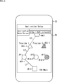
- FIG. 4 is a diagram showing an example of an Association AP setting screen on the user terminal 11.
- the display unit 31 of the user terminal 11 shown in FIG. 4 displays the setting screen of the Association AP in the wireless communication system of FIG.
- the Association AP setting screen includes information on connectable APs located around the user terminal 11 when connecting to the data server 12, and the user selects the optimum AP using the Association AP setting screen. It is configured to be able to.
- association AP setting screen In the top of the Association AP setting screen, in the wireless communication system shown in FIG. 1, information about AP1 to AP3 that can be connected to the user terminal 11 (SSID, service provider connection information, etc.) can be selected by the user using the cursor. It is shown.
- icons M11 indicating user terminals 11, icons M14-1 to M14-3 indicating AP1 to AP3, and icons M15-1 and M15-2 indicating Provider1 and Provider2 are displayed. .. Further, between the icon M11 of the user terminal 11 and the icon M14-1 of the AP1, the route L1 between the user terminal 11 and the AP1 selected by the cursor is shown by a solid line. Further, between the icon M14-1 of AP1 and the icon M15-1 of Provider1, the route L2 scheduled to be connected by the user terminal 11 connecting to AP1 is indicated by a broken line.
- the user can select the AP he / she wants to associate with by looking at the Association AP setting screen and clicking the icon of the desired AP, for example.
- FIG. 5 is a diagram showing an example of a data server setting screen in the user terminal 11.
- the display unit 31 of the user terminal 11 shown in FIG. 5 displays the setting screen of the data server in the wireless communication system of FIG.
- the setting screen of this data server is displayed, for example, after the distribution application is started.
- the upper part of the data server setting screen is configured so that the data server can be selected by entering the URL of the data server that can distribute the content data of the distribution application.
- the user can select the data server to acquire the content data by looking at the setting screen of the data server and inputting, for example, the URL of the desired data server.
- FIG. 6 is a diagram showing a configuration example of a coordinated request frame (Coordinate Request frame).
- the cooperative transmission request frame of FIG. 6 is transmitted from the user terminal 11 to the AP for the setup of cooperative transmission.
- the configuration of the coordinated transmission request frame includes the coordinated transmission control information element (Coordinate Control IE) and the application control information element (Application Control IE) following the MAC header, and FCS (Frame Check Sequence) is added to the end of the frame. Will be added.
- Coordinat Control IE Coordinate Control information element
- Application Control IE Application Control information element
- FCS Frame Check Sequence
- the MAC header of the cooperative transmission request frame includes parameters such as FrameControl, Duration, DestinationAddress, SourceAddress, ReceiveAddress, TransmitAddress, and SequenceControl.
- Frame Control indicates the frame format. Duration indicates the duration of the frame. Destination Address is an address that identifies the destination device. SourceAddress is an address that identifies the sending device. ReceiveAddress is an address that identifies the receiving device. TransmitAddress is an address that identifies the destination device. SequenceControl is information indicating sequence control. FCS is a frame error detection code.
- FIG. 7 is a diagram showing a configuration example of the cooperative transmission control information element.
- the cooperative transmission control information element of FIG. 7 is composed of IEType for identifying a predetermined information element, Length indicating the length of information, and parameters required for setting up cooperative transmission.
- the parameters required to set up coordinated transmission consist of TerminalAddress, CoordinateAPAddress, CoordinateAPAddress, OperatorInfo, ProviderInfo, DatabaseAddress, ApplicationType, and so on.
- Terminal Address is the address of the user terminal.
- Coordinate AP Address is the address of a plurality of APs to be coordinated.
- OperatorInfo is information that identifies a telecommunications carrier, if necessary.
- ProviderInfo is information that identifies a service provider.
- DatabaseAddress is the address of the data server.
- ApplicationType is information indicating the format of the distribution application.
- FIG. 8 is a diagram showing a configuration example of the application control information element.
- the application control information element of FIG. 8 is composed of IEType that identifies a predetermined information element, Length indicating the length of information, and parameters necessary for setting up the application.
- the parameters required to set up the application consist of TerminalAddress, DatabaseAddress, ApplicationType, ServiceType, ContentsDirectory, ContentsFilename, FileType, FileSize, etc.
- Terminal Address is the address of the user terminal.
- DatabaseAddress is the address of the data server.
- Terminal Address and Database Address identify end-to-end connections.
- Application Type is information indicating the format of the distribution application.
- ServiceType is information that identifies the service of the distribution application to be operated.
- the Contents Directory is information on the contents directory stored in the data server.
- ContentsFilename is information indicating the file name of the content.
- FileType is information indicating the file format of the content.
- FileSize is information indicating the file size of the content.
- FIG. 9 is a diagram showing a configuration example of a coordinated transmission display frame (Coordinate Indication frame).
- the cooperative transmission display frame of FIG. 9 is transmitted from the AP to the service provider for the cooperative transmission setup.
- the configuration of the cooperative transmission display frame includes the cooperative transmission control information element of FIG. 7 and the application control information element of FIG. 8 following the MAC header, and FCS is added to the end of the frame.
- the MAC header of the cooperative transmission display frame includes parameters such as FrameControl, Duration, DestinationAddress, SourceAddress, ReceiveAddress, TransmitAddress, and SequenceControl.
- FIG. 10 is a diagram showing a configuration example of a coordinate confirmation frame (Coordinate Confirmation frame).
- the cooperative transmission confirmation frame of FIG. 10 is transmitted from the service provider to the AP for the setup of cooperative transmission.
- the MAC header of the cooperative transmission confirmation frame is composed of the cooperative transmission control information element of FIG. 7, the application control information element of FIG. 8, and the network control information element (Network Control IE) of FIG. 11 to be described later. Included, with FCS added to the end of the frame.
- the MAC header of the cooperative transmission confirmation frame includes parameters such as FrameControl, Duration, DestinationAddress, SourceAddress, ReceiveAddress, and TransmitAddress.
- FIG. 11 is a diagram showing a configuration example of a network control information element.
- the network control information element of FIG. 11 is an IE Type that identifies a predetermined information element, a length that indicates the length of information, and parameters necessary for selecting an AP that executes (starts) cooperative transmission and setting up a communication route setting. Consists of.
- the parameters required to set up the selection communication route setting of the AP that executes (starts) cooperative transmission are composed of Support Protocol, Version, Attribute, Throughput, Cost, Speed, Latency, Delay, Congestion, etc.
- Application Type is information indicating the supported protocol. Version is the version information of the network. Attribute is information indicating the attribute of the network. Throughput is information indicating the throughput capacity of the network. Cost is information indicating the cost of the network. Speed is information indicating the communication speed of the network. Latency is information that indicates the latency of the network. Delay is information indicating the amount of delay in the network. Congestion is information indicating the congestion status of the network.
- FIG. 12 is a diagram showing a configuration example of a coordinated response frame.
- the cooperative transmission response frame of FIG. 12 is transmitted from the AP to the user terminal 11 for the setup of cooperative transmission.
- the configuration of the cooperative transmission response frame includes the cooperative transmission control information element of FIG. 7, the application control information element of FIG. 8, and the network control information element of FIG. 11 following the MAC header, and FCS is added to the end of the frame. Will be done.
- the MAC header of the cooperative transmission response frame includes parameters such as FrameControl, Duration, DestinationAddress, SourceAddress, ReceiveAddress, and TransmitAddress.
- FIG. 13 is a diagram showing a configuration example of an application request frame (Application Request frame).
- the application request frame of FIG. 13 is transmitted from the service provider to the data server 12 for setting up the application.
- the configuration of the application request frame includes the application control information element shown in FIG. 8 following the MAC header, and FCS is added to the end of the frame.
- the MAC header of the application request frame includes parameters such as FrameControl, Duration, DestinationAddress, SourceAddress, ReceiveAddress, TransmitAddress, SequenceControl, and QoSControl.
- QoS Control is service quality control information.
- FIG. 14 is a diagram showing a configuration example of an application response frame (Application Response frame).
- the application response frame of FIG. 14 is transmitted from the data server 12 to the service provider for setting up the application.
- the configuration of the application response frame includes the application control information element of FIG. 8 and the network control information element of FIG. 11 following the MAC header, and FCS is added to the end of the frame.
- the MAC header of the application response frame includes parameters such as FrameControl, Duration, DestinationAddress, SourceAddress, ReceiveAddress, TransmitAddress, and SequenceControl.
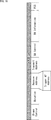
- FIG. 15 is a diagram showing a configuration example of a data frame to be cooperatively transmitted.
- the data frame of FIG. 15 is a general A-MPDU (Aggregation MAC protocol data unit) frame, and is configured by adding Padding (Pad) at the end to a plurality of A-MPDU subframes as needed. ..
- A-MPDU Aggregation MAC protocol data unit
- the A-MPDU subframe is composed of an MPDU containing a delimiter and actual data, with a padding added at the end as necessary.
- FIG. 16 is a diagram showing a configuration example of a Block ACK frame.
- the Block ACK frame in FIG. 16 is composed of Frame Control, Duration, Receive address (RA), Transmit Address (TA), BA Control, BA Information, FCS, and the like.
- Frame Control is information indicating frame control. Duration is information indicating the frame duration. Receiveaddress is a recipient address. Transmit Address is the source address.
- BAControl is information indicating BlockACK control. BA Information is information related to Block ACK.
- FIG. 17 is a diagram showing another example of the AP / route setting screen in the user terminal 11.
- the route L11 shown between the icon M11 and the icon M14-3, the route L12 shown between the icon M14-3 and the icon M15-2, and the icon M15-2 The path L13 shown between the icons M12 is shown by the dashed line.
- the AP / route setting screen in which AP3 and Provider2 are selected according to the user's instruction is shown, and AP3 is selected as the AP that can be co-transmitted with AP1 in the route shown by the broken line. Indicates that the route is connected in some cases.
- AP3 connected to Provider2 different from Provider1 is selected by the user's instruction. It is displayed in the state of.
- the estimated speed of the maximum throughput when the route selected by selecting the AP is used in addition to the currently connected route is displayed at the lower right of the AP / route setting screen.
- the estimated speed at least one of the estimated speed of the route selected by selecting the AP and the estimated speed of the currently connected route may be displayed.
- information related to such communication status and communication status may be displayed.
- the routes selected by the AP selection including the routes with different service providers, are sequentially displayed, so that the user can select the plurality of APs that execute cooperative transmission and the routes to the data server 12. , Can be selected according to the communication status.
- FIG. 18 is a diagram showing another example of the communication sequence of the present technology.
- FIG. 18 shows the flow of signals exchanged between the user terminals 11, AP1 to AP3, Provider1, Provider2, and the data server 12 in the wireless communication system of FIG.
- This communication sequence shows the passage of time from top to bottom. Therefore, the communication sequence will be described below in order from the top with the passage of time.
- FIG. 18 shows an example in which cooperative transmission is performed by AP1 connected to Provider1 and AP3 connected to Provider2 different from Provider1.
- time t201 to time t209, time t221 to time t226, step time t241, and time t242 in FIG. 18 are the same as those in time t1 to time t9, time t21 to time t26, time t41, and time t42 in FIG. Since processing is performed, the description thereof will be omitted.
- time t281 to the time t288, the time t311 and the time t331, and the time t332 in FIG. 18 perform the same processing as the time t81 to the time t88, the time t111, the time t131, and the time t132 in FIG. Is omitted.
- the user terminal 11 determines whether or not cooperative transmission is necessary at time t210.
- the plurality of APs performing cooperative transmission collect Beacon information, Association Resp information, and Application Resp information. By analyzing it, it may be automatically determined by the user terminal 11.
- a plurality of APs for cooperative transmission are selected by the user by displaying the AP / route setting screen of FIG. 17 generated based on the Beacon information, the Association Resp information, and the Application Resp information. It may be decided by.
- the user terminal 11 transmits Coordinate Req to AP1 at time t211, for example, when cooperative transmission between AP1 and AP3 is required.
- AP1 receives the Coordinate Req transmitted from the user terminal 11 at time t227. AP1 sends Coordinate Indi to Provider1 at time t228 to notify the setting request of coordinated transmission.
- Provider1 receives Application Req sent from AP2 at time t289. Provider1 notifies the setting request of cooperative transmission by transmitting Application Req to the data server 12 as needed at time t290.
- the data server 12 receives Application Req sent from Provider 1 at time t333.
- the data server 12 transmits Application Resp to Provider 1 at time t334.
- Provider1 receives ApplicationResp sent from the data server 12 at time t291. As a result, the connection with the data server 12 is confirmed, so the Provider 1 transmits the Coordinate Conf to the AP1 at the time t292.
- AP1 receives the Coordinate Conf sent from Provider 1 at time t229. AP1 transmits Coordinate Resp for Coordinate Conf to the user terminal 11 at time t230.
- the user terminal 11 receives the Coordinate Resp transmitted from AP1 at time t212. Further, the user terminal 11 transmits the Coordinate Req to the AP3 at the time t213.
- AP3 receives the Coordinate Req transmitted from the user terminal 11 at time t263. AP3 sends Coordinate Indi to Provider2 at time t264 and notifies the setting request of coordinated transmission.
- Route Request frame The configuration of the Route Request frame will be described later in FIG.
- the data server 12 receives the Route Req transmitted from the Provider 2 at the time t335, and transmits the route setting response (Route Resp) which is the response to the Route Req to the Provider 2 at the time t336.
- the configuration of the Route Response frame will be described later in FIG.
- Provider2 receives RouteResp transmitted from the data server 12 at time t314, and transmits CoordinateConf to AP3 at time t315.
- AP3 receives the Coordinate Conf sent from Provider 2 at time t265. AP3 transmits Coordinate Resp for Coordinate Conf to the user terminal 11 at time t266.
- the user terminal 11 receives the Coordinate Resp transmitted from the AP3 at time t214. After receiving the Coordinate Resp, the user terminal 11 sets the reception for the cooperative transmission from each AP.
- the data server 12 transmits the content data (Download Data) to Provider 1 at time t337.
- Provider1 receives Download Data transmitted from the data server 12 at time t293 and generates Distribution Data to be distributed to AP1.
- Provider1 sends Distribution Data to AP1 at time t294.
- AP1 receives Distribution Data at time t231.
- the data server 12 transmits Download Data to Provider 2 at time t338.
- Provider2 receives Download Data transmitted from the data server 12 at time t316 and generates Distribution Data to be distributed to AP3.
- Provider2 sends Distribution Data to AP3 at time t317.
- AP3 receives Distribution Data sent from Provider2 at time t267.
- AP1 transmits a coordinate trigger (Coordinate trigger) at time t232.
- AP3 receives the Coordinate trigger sent from AP1 at time t268.
- the user terminal 11 receives the Coordinate trigger transmitted from AP1 at time 215.
- AP1 and AP3 transmit Distribution Data as coordinated data (Coordinate Data) to the user terminal 11 at time t233 and time t269 (same timing).
- the user terminal 11 receives the Coordinate Data transmitted from AP1 and the Coordinate Data transmitted from AP2 at time t216. If all the data is correctly received, the user terminal 11 returns a Block ACK to AP1 at time t217.
- the AP that the user terminal 11 returns the Block ACK is an AP that performs retransmission control, and may be AP3 if AP3 controls retransmission.
- the AP1 receives the Block ACK transmitted from the user terminal 11 at time t234. When the AP1 determines that all the data has arrived correctly at the user terminal 11 based on the Block ACK, it transmits the Distribution Resp to the Provider 1 at time 235, if necessary.
- Provider1 receives the Distribution Resp transmitted from AP1 at time t295, and then the cooperative transmission of the content data (Download Data) transmitted at time t337 and time t338 is completed.
- FIG. 19 is a diagram showing a configuration example of a route setting request frame.
- the route setting request frame of FIG. 19 is used when being transmitted from the service provider to the data server 12 for setting up the transmission route of the content data, and is described as a Route Request frame.
- the configuration of the MAC header of the route setting request frame includes the cooperative transmission control information element of FIG. 7 and the application control information element of FIG. 8 following the MAC header, and FCS is added to the end of the frame.
- the MAC header of the route setting request frame includes parameters such as FrameControl, Duration, DestinationAddress, SourceAddress, ReceiveAddress, TransmitAddress, and SequenceControl.
- FIG. 20 is a diagram showing a configuration example of a route setting response frame (Route Response frame).
- the route setting response frame of FIG. 20 is transmitted from the data server 12 to the service provider for setting up the transmission route.
- the configuration of the route setting response frame includes the cooperative transmission control information element of FIG. 7, the application control information element of FIG. 8, and the network control information element of FIG. 11 following the MAC header, and FCS is added to the end of the frame. Will be done.
- the MAC header of the route setting response frame includes parameters such as FrameControl, Duration, DestinationAddress, SourceAddress, ReceiveAddress, and TransmitAddress.
- FIG. 21 is a block diagram showing a basic configuration example of each communication device such as a user terminal 11, a data server 12, a wireless communication device 14, or a communication device 15.
- the communication device of FIG. 21 is composed of a network connection module 51, an information input module 52, a device control module 53, an information output module 54, and a wireless communication module 55.
- the user terminal 11, the data server 12, the wireless communication device 14, and the communication device 15 are each composed of modules required for the communication device shown in FIG. 21, or the communication device shown in FIG. 21 is unnecessary.
- the parts may be simplified or not incorporated.
- the network connection module 51 When the network connection module 51 operates as a data server 12, a wireless communication device 14, or a communication device 15 under the control of the device control module 53, a function such as a communication modem for connecting to the Internet 13 is implemented. It is composed.
- the network connection module 51 connects to the Internet 13 via a public communication line and an Internet service provider.
- the information input module 52 outputs information for transmitting an instruction input by the user to the device control module 53.
- the information input module 52 includes push buttons, a keyboard, a touch panel, and the like.
- the device control module 53 is composed of a CPU (Central Processing Unit), a ROM (Read Only Memory), a RAM (Random Access Memory), and the like.
- the device control module 53 executes a program stored in a ROM or the like, causes an application to function in an upper layer, and controls each part of a communication device to operate as each communication device. Further, the device control module 53 has a memory 53A, and stores information necessary for processing in the memory 53A.
- the information output module 54 outputs information regarding the operating state of the communication device supplied from the device control module 53, or information obtained via the Internet 13.
- the information output module 54 includes a display device such as an LED, a liquid crystal panel, or an organic display (for example, the display unit 31 in FIG. 3), a speaker that outputs voice or music, or the like.
- the information output module 54 displays and notifies the user of necessary information.
- the wireless communication module 55 transmits the data supplied from the device control module 53 to another communication device by performing wireless communication.
- the wireless communication module 55 receives data transmitted from another communication device by performing wireless communication, and outputs the received data to the device control module 53.
- FIG. 22 is a block diagram showing a configuration example of the wireless communication module 55 in the case of the user terminal 11.
- the wireless communication module 55 includes an interface 101, a transmission buffer 102, a transmission sequence management unit 103, a transmission frame construction unit 104, a cooperative transmission / reception control unit 105, and a timing control unit 106. Further, the wireless communication module 55 includes transmission signal processing units 107-1 and 107-2, transmission / reception antenna units 108, reception signal processing units 109-1 and 109-2, reception frame analysis unit 110, reception sequence management unit 111, and the like. A receive buffer 112 is provided.
- the interface 101 functions as an interface for exchanging information input from the user from the device control module 53, data supplied from the Internet 13, or information provided to the user in a predetermined signal format.
- the interface 101 outputs the data supplied from the device control module 53 to the transmission buffer 102.
- the interface 101 outputs the content data stored in the reception buffer 112 to the device control module 53.
- the transmission buffer 102 temporarily stores the received data when the information input from the user or the data to be wirelessly transmitted is received via the interface 101.
- the transmission sequence management unit 103 manages the transmission sequence for the data to be transmitted. Further, the transmission sequence management unit 103 acquires data from the transmission buffer 102 and outputs the data to the transmission frame construction unit 104 based on the transmission sequence.
- the transmission frame construction unit 104 outputs the data supplied from the transmission sequence management unit 103 to the transmission signal processing unit 107-1 according to the transmission timing supplied from the timing control unit 106.
- the transmission frame construction unit 104 manages the transmission sequence according to the instruction from the cooperative transmission / reception control unit 105.
- the data supplied from the unit 103 is converted into a predetermined frame format as the first data and the second data to be cooperatively transmitted.
- the transmission frame construction unit 104 sends the first data frame and the second data frame to be coordinatedly transmitted according to the transmission timing supplied from the timing control unit 106, respectively, to the transmission signal processing unit 107-1 and Output to 107-2.
- the transmission frame construction unit 104 generates control frames such as an association request, an application request, a cooperative transmission request, a route setting request, and a block ACK according to an instruction from the cooperative transmission / reception control unit 105.
- the transmission frame construction unit 104 outputs the generated control frame to the transmission signal processing unit 107-1 according to the transmission timing controlled by the timing control unit 106.
- the cooperative transmission / reception control unit 105 controls the transmission / reception of frames based on the information input from the user supplied via the interface 101 and the header information supplied from the reception frame analysis unit 110.
- the cooperative transmission / reception control unit 105 controls the transmission / reception of the control frame, the execution of the cooperative transmission, and the simultaneous reception of the cooperatively transmitted data by controlling the transmission frame construction unit 104 and the timing control unit 106.
- the cooperative transmission / reception control unit 105 has a memory 105A.
- the cooperative transmission / reception control unit 105 stores information related to cooperative transmission and the like based on the information input from the user and the header information supplied from the reception frame analysis unit 110 supplied via the interface 101 in the memory 105A. Store in and generate the information required for display. Information related to cooperative transmission and information necessary for display are output to the device control module 53 via the interface 101.
- the timing control unit 106 transmits the transmission timing to the transmission frame construction unit 104, the transmission signal processing units 107-1 and 107-2, and the transmission / reception antenna unit 108 based on the instruction from the cooperative transmission / reception control unit 105. To control.
- the timing control unit 106 controls the reception timing for the reception signal processing units 109-1 and 109-2 and the transmission / reception antenna unit 108 based on the header information supplied from the reception frame analysis unit 110 and the like.
- the transmission signal processing unit 107-1 transmits the control frame supplied from the transmission frame construction unit 104 and the frame of the first data to be cooperatively transmitted according to the transmission timing controlled by the timing control unit 106, to the transmission / reception antenna unit 108. Output to.
- the transmission signal processing unit 107-2 outputs a frame of the second data for cooperative transmission supplied from the transmission frame construction unit 104 to the transmission / reception antenna unit 108 according to the transmission timing controlled by the timing control unit 106.
- the transmission signal processing unit 107-1 becomes active. Further, hereinafter, when it is not necessary to distinguish between the transmission signal processing unit 107-1 and 107-2, the transmission signal processing unit 107 is referred to.
- the transmission / reception antenna unit 108 coordinates the first data frame and the second data frame supplied from the transmission signal processing units 107-1 and 107-2 according to the transmission timing controlled by the timing control unit 106. Send.
- the transmission / reception antenna unit 108 receives the first data frame and the second data frame that are cooperatively transmitted according to the reception timing controlled by the timing control unit 106.
- the transmission / reception antenna unit 108 outputs the received first data frame and the second data frame to the reception signal processing units 109-1 and 109-2, respectively.
- the transmission / reception antenna unit 108 transmits the control frame supplied from the transmission signal processing unit 107-1 according to the transmission timing controlled by the timing control unit 106.
- the transmission / reception antenna unit 108 outputs the received control frame to the reception signal processing unit 109-1.
- the reception signal processing unit 109-1 processes the frame of the first data and the control frame of the coordinated transmission supplied from the transmission / reception antenna unit 108 according to the reception timing controlled by the timing control unit 106.
- the reception signal processing unit 109-1 outputs the processed first data frame or control frame to the reception frame analysis unit 110.
- the reception signal processing unit 109-2 processes the frame of the second data that is cooperatively transmitted and is supplied from the transmission / reception antenna unit 108 based on the reception timing supplied from the timing control unit 106.
- the reception signal processing unit 109-2 outputs the processed frame of the second data to the reception frame analysis unit 110.
- the received signal processing unit 109-1 becomes active. Further, hereinafter, when it is not necessary to distinguish between the received signal processing units 109-1 and 109-2, it is referred to as the received signal processing unit 109.
- the reception frame analysis unit 110 analyzes the frame supplied from the reception signal processing unit 109 and extracts necessary header information and data.
- the reception frame analysis unit 110 outputs the extracted header information and the like to the cooperative transmission / reception control unit 105.
- the reception frame analysis unit 110 outputs the extracted data to the reception sequence management unit 111.
- the reception sequence management unit 111 manages the reception sequence of the data supplied from the reception frame analysis unit 110.
- the reception sequence management unit 111 stores data in the reception buffer 112 based on the reception sequence.
- the reception buffer 112 temporarily stores data. When data is collected in the receive buffer 112, the collected data is configured as content data and output to the interface 101.
- AP1 to AP3 transmit Beacon, respectively.
- the reception signal processing unit 109-1 receives the Beacon and supplies it to the reception frame analysis unit 110 (t1 to t3 in FIG. 3).
- the reception frame analysis unit 110 analyzes the frame supplied from the reception signal processing unit 109 and extracts the communication parameter information included in the Beacon.
- the reception frame analysis unit 110 outputs the communication parameter information to the cooperative transmission / reception control unit 105.
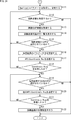
- step S101 the cooperative transmission / reception control unit 105 determines whether or not the Beacon has been received.
- the process proceeds to step S102.
- the communication parameter information includes Provider information related to the Provider that each AP connects to the Internet 13.
- step S102 the cooperative transmission / reception control unit 105 acquires the provider information to be connected from the communication parameter information and stores it in the memory 105A. Communication parameter information may also be stored.
- step S101 If it is not determined in step S101 that the Beacon has been received, the process of step S102 is skipped and the process proceeds to step S103.
- step S103 the cooperative transmission / reception control unit 105 determines whether or not an AP to perform association has been set based on the status of surrounding APs obtained by Beacon. If it is determined in step S103 that the AP to be associated is set (t4 in FIG. 3), the process proceeds to step S104.
- step S104 the cooperative transmission / reception control unit 105 controls the transmission frame construction unit 104 to transmit the Association Req to a desired AP (for example, AP1) (t5 in FIG. 3).
- a desired AP for example, AP1
- the transmission frame construction unit 104 generates an Association Req frame and causes the transmission signal processing unit 107-1 to transmit the Association Req frame.
- AP1 When AP1 receives Association Req, it sends Association Req to Provider 1 (t24 in Fig. 3). Further, the AP1 receives the AssociationResp for the Association request from the Provider1 and transmits it to the user terminal 11 (t26 in FIG. 3).
- the reception signal processing unit 109-1 receives the Association Resp and supplies it to the reception frame analysis unit 110 (t6 in FIG. 3).
- the reception frame analysis unit 110 analyzes the reception frame supplied from the reception signal processing unit 109 and extracts each parameter of the header information and the information element.
- the reception frame analysis unit 110 outputs header information and each parameter of the required information element to the cooperative transmission / reception control unit 105.
- step S105 the cooperative transmission / reception control unit 105 determines whether or not the Association Resp has been received.
- the process proceeds to step S106.
- step S106 the cooperative transmission / reception control unit 105 acquires the Association AP information, which is the information of the Association AP, from each parameter of the header information, and stores it in the memory 105A.
- step S105 if it is determined in step S105 that the Association Resp has not been received, the process returns to step S103, another AP to be associated is selected, and the subsequent processing is repeated.
- step S107 the cooperative transmission / reception control unit 105 determines whether or not a predetermined distribution application has been started by the user. If it is determined in step S107 that the distribution application has been started, the process proceeds to step S108. After starting the distribution application, for example, information on desired content data is input to the user terminal 11 in response to a user's instruction. That is, the information of the desired content data is supplied to the cooperative transmission / reception control unit 105 via the information input module 52, the device control module 53, and the interface 101.
- step S108 the cooperative transmission / reception control unit 105 reads the connected Provider information from the memory 105A and acquires it.
- step S109 the cooperative transmission / reception control unit 105 controls the transmission frame construction unit 104 and transmits Application Req to Provider 1 connected to the data server 12 in which the desired content data is stored based on the Provider information. (T8 in Fig. 3).
- the transmission frame construction unit 104 generates an Application Req frame and causes the transmission signal processing unit 107-1 to transmit the Application Req frame.
- Application Req is sent to Provider 1 via the associated AP1.
- Provider1 When Provider1 receives ApplicationReq, it sends ApplicationResp to ApplicationReq (t88 in Fig. 3). Application Resp is transmitted to the user terminal 11 via the associated AP1.
- the reception signal processing unit 109-1 receives the Application Resp and supplies it to the reception frame analysis unit 110 (t9 in FIG. 3).
- the reception frame analysis unit 110 analyzes the reception frame supplied from the reception signal processing unit 109 and extracts each parameter of the header information and the information element.
- the reception frame analysis unit 110 outputs header information and each parameter of the required information element to the cooperative transmission / reception control unit 105.
- step S110 the cooperative transmission / reception control unit 105 determines whether or not Application Resp has been received.
- the cooperative transmission / reception control unit 105 determines in step S110 that the Application Resp has been received based on each parameter of the header information supplied from the reception frame analysis unit 110, the process proceeds to step S111 in FIG. 24. ..
- step S110 if it is determined in step S110 that Application Resp has not been received, the process returns to step S101 and the subsequent processing is repeated.
- step S103 if it is determined in step S103 that the AP for associating is not set, or if it is determined in step S107 that the distribution application is not started, the process returns to step S101 and the subsequent processing. Is repeated.
- step S111 of FIG. 24 the cooperative transmission / reception control unit 105 acquires parameters related to the application, parameters related to the communication path, and the like from each parameter of the header information and the information element, and stores them in the memory 105A.
- step S112 the cooperative transmission / reception control unit 105 determines whether or not to set cooperative transmission. If the cooperative transmission is set and it is determined in step S112, the process proceeds to step S113.
- step S113 the cooperative transmission / reception control unit 105 reads and acquires information on surrounding APs from the memory 105A or the like.
- the acquired information on surrounding APs includes communication parameter information, application parameters, communication path parameters, and the like.
- Information about the surrounding APs is output to the device control module 53 via the interface 101.
- step S114 the device control module 53 displays a list of cooperative transmission possible APs (for example, the AP / route setting screen of FIG. 2) on the information output module 54 based on the information about the surrounding APs. That is, a list of cooperative transmission-capable APs connected to the data server 12 via the service provider according to the instruction of the corresponding distribution application is displayed.
- a list of cooperative transmission-capable APs connected to the data server 12 via the service provider according to the instruction of the corresponding distribution application is displayed.
- the user who sees the displayed list of co-transmissible APs selects a desired AP from the co-transmissible APs by using the information input module 52.
- the information input module 52 outputs AP selection information to the device control module 53 in response to a user instruction.
- the device control module 53 outputs the AP selection information to the wireless communication module 55.
- the AP selection information is supplied to the cooperative transmission / reception control unit 105 via the interface 101.
- step S115 the cooperative transmission / reception control unit 105 determines whether or not the AP for cooperative transmission is selected. If it is determined in step S115 that the AP to be coordinated is selected, the process proceeds to step S116.
- step S116 the cooperative transmission / reception control unit 105 temporarily sets the parameters of the cooperative transmission on the communication terminal on the data receiving side for the setup of the cooperative transmission based on the selection information of the AP.
- step S117 the coordinated transmission / reception control unit 105 controls the transmission frame construction unit 104, and in this embodiment, for example, the coordinate Req is transmitted to the AP2 for coordinated transmission (t11 in FIG. 3).
- the transmission frame construction unit 104 generates a Coordinate Req frame and causes the transmission signal processing unit 107-1 to transmit the Coordinate Req frame.
- AP2 Upon receiving the Coordinate Req, AP2 sends a Resp (Coordinate Resp) to the Coordinate Req (t46 in Fig. 3).
- the reception signal processing unit 109-1 receives the Coordinate Resp and supplies it to the reception frame analysis unit 110 (t12 in FIG. 3).
- the reception frame analysis unit 110 analyzes the frame supplied from the reception signal processing unit 109 and extracts each parameter of the header information.
- the reception frame analysis unit 110 outputs each parameter of the header information to the cooperative transmission / reception control unit 105.
- step S118 the coordinated transmission / reception control unit 105 determines whether or not the Coordinate Resp has been received. If it is determined in step S118 that CoordinateResp has not been received, the process returns to step S112, and the subsequent processing is repeated.
- step S115 determines whether the AP for cooperative transmission is not selected. If it is determined in step S115 that the AP for cooperative transmission is not selected, the process returns to step S112 and the subsequent processing is repeated.
- step S118 determines whether the Coordinate Resp has been received. If it is determined in step S118 that the Coordinate Resp has been received, the process proceeds to step S119.
- step S119 the cooperative transmission / reception control unit 105 determines whether or not another AP for cooperative transmission is selected. If it is determined in step S119 that another AP to be coordinated is selected, the process proceeds to step S120.
- step S120 the coordinated transmission / reception control unit 105 controls the transmission frame construction unit 104, and similarly to step S117, in this embodiment, for example, the coordinate Req is transmitted to another AP1 for coordinated transmission. (T13 in FIG. 3).
- AP1 Upon receiving the Coordinate Req, AP1 sends a Resp (Coordinate Resp) to the Coordinate Req (t30 in Fig. 3).
- step S121 the coordinated transmission / reception control unit 105 determines whether or not Coordinate Resp has been received, as in step S118. If it is determined in step S121 that the Coordinate Resp has not been received, the process returns to step S119, another AP is selected as the AP for co-transmission, and the subsequent processing is repeated.
- step S121 If it is determined in step S121 that the Coordinate Resp has been received, the process proceeds to step S122. From the above, it means that the cooperative transmission is permitted from multiple APs.
- step S122 the cooperative transmission / reception control unit 105 controls the timing control unit 106, and sets the reception signal processing units 109-1 and 109-2 to receive the data cooperatively transmitted from each AP. Make the reception settings. After that, the communication setting process ends.
- step S112 determines whether the coordinated transmission is not set, or if it is determined in step S119 that the Coordinate Resp is not received.
- ⁇ Cooperative reception processing of user terminals> 25 and 26 are flowcharts for explaining the cooperative reception process of the user terminal 11.
- FIGS. 25 and 26 a process of receiving data cooperatively transmitted from a plurality of APs preset by the communication setting process of FIGS. 23 and 24 is shown.
- Trigger frame is transmitted from one of the APs (for example, AP1) (t32 in Fig. 3).
- the reception signal processing unit 109-1 receives the Trigger frame and supplies it to the reception frame analysis unit 110 (t15 in FIG. 3).
- the reception frame analysis unit 110 analyzes the Trigger frame supplied from the reception signal processing unit 109 and extracts the parameters of the Trigger frame.
- the parameters of the Trigger frame include data reception timing, cooperative transmission specification information, transmission setting information of each AP, and the like.
- the reception frame analysis unit 110 outputs the Trigger frame parameters to the cooperative transmission / reception control unit 105.
- step S201 the cooperative transmission / reception control unit 105 waits until the Trigger frame is received. Then, when the cooperative transmission / reception control unit 105 determines in step S201 that the Trigger frame has been received based on the parameters of the Trigger frame supplied from the reception frame analysis unit 110, the process proceeds to step S202.
- step S202 the cooperative transmission / reception control unit 105 acquires the parameters required for cooperative transmission from the parameters of the Trigger frame.
- step S203 the cooperative transmission / reception control unit 105 determines whether or not cooperative transmission is set based on the acquired parameters and the like. If it is determined in step S203 that the cooperative transmission is not set, the process returns to step S201, and the subsequent processes are repeated.
- step S203 when cooperative transmission is set by the communication setting process of FIGS. 23 and 24, it is determined that cooperative transmission is set, and the process proceeds to step S204.
- step S204 the cooperative transmission / reception control unit 105 determines whether or not there is an AP for which cooperative transmission is set. If it is determined in step S204 that there is no AP for which cooperative transmission is set, the process returns to step S201, and the subsequent processing is repeated.
- step S204 If it is determined in step S204 that there is an AP for which cooperative transmission is set, the process proceeds to step S205.
- step S205 the cooperative transmission / reception control unit 105 controls the timing control unit 106, and causes the reception signal processing unit 109-1 to set the reception of the first cooperative transmission data.
- step S206 the cooperative transmission / reception control unit 105 determines whether or not there is another AP for which cooperative transmission is set. If it is determined in step S206 that there is another AP set for cooperative transmission, the process proceeds to step S207.
- step S207 the cooperative transmission / reception control unit 105 controls the timing control unit 106, and causes the reception signal processing unit 109-2 to set the reception of the second cooperative transmission data. After that, the process returns to step S206, and the subsequent processes are repeated. That is, when more, for example, three or more APs are set for cooperative transmission, the user terminal 11 may be configured so that the reception is set as appropriate.
- step S206 If it is determined in step S206 that there is no other AP set for cooperative transmission, the process proceeds to step S208 of FIG.
- AP1 and AP2 transmit cooperative transmission data at the timing specified in the Trigger frame (t33 and t49 in Fig. 3).
- step S208 of FIG. 26 the received signal processing units 109-1 and 109-2 receive the cooperative transmission data (t16 of FIG. 3).
- the reception signal processing units 109-1 and 109-2 receive the cooperative transmission data and supply it to the reception frame analysis unit 110.
- the reception frame analysis unit 110 analyzes each frame of the cooperative transmission data supplied from the reception signal processing unit 109, and extracts data in a predetermined data unit (A-MPDU subframe unit in FIG. 15) and header information parameters. To do.
- the reception frame analysis unit 110 outputs the data of a predetermined data unit to the reception sequence management unit 111, and outputs the parameters to the cooperative transmission / reception control unit 105.
- step S209 the reception sequence management unit 111 determines whether or not the data of a predetermined data unit among the received data can be normally collected. If it is determined that the data of the predetermined data unit can be collected normally, the process proceeds to step S210.
- step S210 the reception sequence management unit 111 acquires the data of a predetermined data unit that has been normally collected and stores it in the reception buffer 112.
- step S209 If it is determined in step S209 that the data of the predetermined data unit could not be collected normally, step S210 is skipped and the process proceeds to step S211.
- step S211 the reception sequence management unit 111 determines whether or not the end of the received data (A-MPDU frame in FIG. 15) has arrived. If it is determined that the end of the received data has not arrived, the process returns to step S208, and the subsequent processing is repeated.
- step S211 If it is determined in step S211 that the end of the received data has arrived, the process proceeds to step S212.
- the reception signal processing unit 109-1 receives the first cooperative transmission data, and at the same time, the reception signal processing unit 109-2 receives the second cooperative transmission data, and the processing is performed respectively. It is composed.
- step S212 the reception sequence management unit 111 determines whether or not there is data in a predetermined data unit that can be normally collected. If it is determined in step S212 that there is data in a predetermined data unit that can be normally collected, the process proceeds to step S213.
- step S213 the reception sequence management unit 111 collects data in a predetermined data unit from the reception results of the first cooperative transmission data and the second cooperative transmission data from the reception buffer 112 and the like, and receives the reception data (A). -MPDU frame) is constructed and stored in the receive buffer 112.
- step S212 If it is determined in step S212 that there is no data in a predetermined data unit that can be normally collected, step S213 is skipped and the process proceeds to step S214.
- step S214 the cooperative transmission / reception control unit 105 constructs the Block ACK information which is the receipt confirmation in the reception sequence management unit 111.
- step S215 the cooperative transmission / reception control unit 105 specifies the AP that performs retransmission control.
- step S216 the cooperative transmission / reception control unit 105 controls the transmission frame construction unit 104 and causes the AP that executes retransmission control to transmit a Block ACK frame (FIG. 16) (t17 in FIG. 3).
- step S217 the cooperative transmission / reception control unit 105 determines whether or not all the data has been received. If it is determined in step S217 that all the data has not been received, the process returns to step S201, and the subsequent processing is repeated. That is, the cooperative transmission / reception control unit 105 waits for the data to be coordinated transmission again.
- step S217 If it is determined in step S217 that all the data has been received, the process proceeds to step S218. Even if retransmission is not performed due to a timeout or the like before all the data is received, the process proceeds to step S218.
- step S218 the reception sequence management unit 111 causes the device control module 53 (application) to output the data stored in the reception buffer 112 via the interface 101.
- the existing AP when executing cooperative transmission, the existing AP can be reused without introducing a new AP.
- the AP is equipped with a cooperative transmission function, it is possible to execute cooperative transmission even if APs from different manufacturers are used.
- the AP can be specified at any time, it is possible to set the optimum AP as needed and execute the cooperative transmission setup, such as when executing the application required by the user.
- the user can select the most suitable AP.
- the user terminal is equipped with a display function such as a display, the user can easily display the existence of the surrounding AP corresponding to the cooperative transmission.
- the user terminal is equipped with an interface for inputting the user's instruction, the user can easily specify an arbitrary AP for executing cooperative transmission.
- the user can select the most suitable AP for the user.
- FIG. 27 is a block diagram showing a configuration example of computer hardware that executes the above-mentioned series of processes programmatically.
- the CPU Central Processing Unit
- ROM Read Only Memory
- RAM Random Access Memory
- An input / output interface 305 is further connected to the bus 304.
- An input unit 306 including a keyboard, a mouse, and the like, and an output unit 307 including a display, a speaker, and the like are connected to the input / output interface 305.
- the input / output interface 305 is connected to a storage unit 308 made of a hard disk, a non-volatile memory, or the like, a communication unit 309 made of a network interface, or a drive 310 for driving the removable media 311.
- the CPU 301 loads the program stored in the storage unit 308 into the RAM 303 via the input / output interface 305 and the bus 304 and executes the program, thereby executing the series of processes described above. Is done.
- the program executed by the CPU 301 is recorded on the removable media 311 or provided via a wired or wireless transmission medium such as a local area network, the Internet, or a digital broadcast, and is installed in the storage unit 308.
- the program executed by the computer may be a program that is processed in chronological order according to the order described in this specification, or may be a program that is processed in parallel or at a necessary timing such as when a call is made. It may be a program in which processing is performed.
- the system means a set of a plurality of components (devices, modules (parts), etc.), and it does not matter whether all the components are in the same housing. Therefore, a plurality of devices housed in separate housings and connected via a network, and a device in which a plurality of modules are housed in one housing are both systems. ..
- this technology can have a cloud computing configuration in which one function is shared by a plurality of devices via a network and processed jointly.
- each step described in the above flowchart can be executed by one device or shared by a plurality of devices.
- one step includes a plurality of processes
- the plurality of processes included in the one step can be executed by one device or shared by a plurality of devices.
- the present technology can also have the following configurations.
- a wireless communication terminal including a communication control unit that starts the setup of the cooperative transmission in order to execute the cooperative transmission in a plurality of wireless communication devices.
- the wireless communication terminal according to (1) wherein the communication control unit transmits a setup request for cooperative transmission to the desired wireless communication device, and receives a response to the setup request from the wireless communication device.
- the communication control unit sets the reception setting of the cooperative transmission executed by the plurality of wireless communication devices.
- the wireless communication terminal according to 2).
- the communication control unit transmits the setup request for cooperative transmission to the plurality of wireless communication devices and receives the response of the setup request from the plurality of wireless communication devices
- the wireless communication terminal according to (1) above which sets the reception of the coordinated transmission to be executed.
- the wireless communication terminal according to (1) above, wherein the setup request for executing the cooperative transmission in the plurality of the wireless communication devices includes the address information of the related communication devices.
- the response to the setup request includes a network control information element necessary for selecting the wireless communication device that causes the plurality of wireless communication devices to execute the cooperative transmission.
- the communication control unit transmits the cooperative transmission setup request to the desired wireless communication device connected to the data server via the service provider in response to an instruction from the corresponding application.
- the wireless communication terminal according to (1) above.
- the communication control unit transmits the setup request to each of the plurality of desired wireless communication devices when the plurality of desired wireless communication devices are via different service providers.
- the described wireless communication terminal 17.
- the wireless communication terminal A wireless communication method for starting the setup of the cooperative transmission in order to execute the cooperative transmission in a plurality of wireless communication devices.
- 11 user terminals 12 data servers, 13 Internet, 14, 14-1 to 14-3 communication devices, 15, 15-1, 15-2 communication devices, 51 network connection modules, 52 information input modules, 53 device control modules, 53A memory, 54 information output module, 55 wireless communication module, 101 interface, 102 transmission buffer, 103 transmission sequence management unit, 104 transmission frame construction unit, 105 coordination / transmission / reception control unit, 105A memory, 106 timing control unit, 107 , 107-1, 107-2 Transmission signal processing unit, 108 Transmission / reception interface unit, 109, 109-1, 109-2 Reception signal processing unit, 110 Reception frame analysis unit, 111 Reception sequence management unit, 112 Reception buffer
Landscapes
- Engineering & Computer Science (AREA)
- Computer Networks & Wireless Communication (AREA)
- Signal Processing (AREA)
- Computer Security & Cryptography (AREA)
- Mobile Radio Communication Systems (AREA)
Abstract
Priority Applications (6)
| Application Number | Priority Date | Filing Date | Title |
|---|---|---|---|
| EP20887888.4A EP4061077A4 (fr) | 2019-11-14 | 2020-10-30 | Terminal de communication sans fil et procédé |
| US17/755,701 US12323910B2 (en) | 2019-11-14 | 2020-10-30 | Wireless communication terminal and method |
| CN202080077155.9A CN114667799A (zh) | 2019-11-14 | 2020-10-30 | 无线通信终端和方法 |
| JP2021556014A JPWO2021095559A1 (fr) | 2019-11-14 | 2020-10-30 | |
| US19/196,316 US20250274853A1 (en) | 2019-11-14 | 2025-05-01 | Wireless communication terminal and method |
| JP2025272791A JP2026034737A (ja) | 2019-11-14 | 2025-12-22 | 処理装置、処理方法、およびプログラム |
Applications Claiming Priority (2)
| Application Number | Priority Date | Filing Date | Title |
|---|---|---|---|
| JP2019206204 | 2019-11-14 | ||
| JP2019-206204 | 2019-11-14 |
Related Child Applications (2)
| Application Number | Title | Priority Date | Filing Date |
|---|---|---|---|
| US17/755,701 A-371-Of-International US12323910B2 (en) | 2019-11-14 | 2020-10-30 | Wireless communication terminal and method |
| US19/196,316 Continuation US20250274853A1 (en) | 2019-11-14 | 2025-05-01 | Wireless communication terminal and method |
Publications (1)
| Publication Number | Publication Date |
|---|---|
| WO2021095559A1 true WO2021095559A1 (fr) | 2021-05-20 |
Family
ID=75912054
Family Applications (1)
| Application Number | Title | Priority Date | Filing Date |
|---|---|---|---|
| PCT/JP2020/040769 Ceased WO2021095559A1 (fr) | 2019-11-14 | 2020-10-30 | Terminal de communication sans fil et procédé |
Country Status (5)
| Country | Link |
|---|---|
| US (2) | US12323910B2 (fr) |
| EP (1) | EP4061077A4 (fr) |
| JP (2) | JPWO2021095559A1 (fr) |
| CN (1) | CN114667799A (fr) |
| WO (1) | WO2021095559A1 (fr) |
Families Citing this family (2)
| Publication number | Priority date | Publication date | Assignee | Title |
|---|---|---|---|---|
| US12439235B2 (en) * | 2022-11-11 | 2025-10-07 | Meta Platforms Technologies, Llc | Systems and methods for ultra-wideband in-band discovery |
| US20240365198A1 (en) * | 2023-04-27 | 2024-10-31 | Cisco Technology, Inc. | Enhanced multi-link operation (mlo) for client distress operation |
Citations (2)
| Publication number | Priority date | Publication date | Assignee | Title |
|---|---|---|---|---|
| JPH113317A (ja) * | 1997-06-13 | 1999-01-06 | Inter Wave Japan:Kk | インターネット接続装置 |
| JP2012217045A (ja) | 2011-03-31 | 2012-11-08 | Fujitsu Ltd | プログラム、情報通信機器および連携方法 |
Family Cites Families (6)
| Publication number | Priority date | Publication date | Assignee | Title |
|---|---|---|---|---|
| CN110380980A (zh) * | 2013-02-22 | 2019-10-25 | 英特尔Ip公司 | 用于接入网络选择和流量路由的系统和方法 |
| BR112015025271A2 (pt) * | 2013-04-10 | 2017-07-18 | Sony Corp | aparelhos de terminal, de processamento de informação e de controle de comunicação |
| JP5714072B2 (ja) * | 2013-09-11 | 2015-05-07 | 株式会社東芝 | 無線通信装置、接続制御方法及び接続制御プログラム |
| RU2645736C2 (ru) * | 2013-12-13 | 2018-02-28 | Телефонактиеболагет Л М Эрикссон (Пабл) | Координация трафика для сеансов связи с участием беспроводных терминалов и серверных устройств |
| KR20250142473A (ko) | 2018-11-08 | 2025-09-30 | 인터디지탈 패튼 홀딩스, 인크 | 무선 로컬 영역 네트워크(wlans)에서 다중 액세스 포인트(multi-ap) 조정을 위한 시스템, 방법 및 장치 |
| US12010748B2 (en) | 2019-01-24 | 2024-06-11 | Sony Group Corporation | Communication device, communication control device, communication method, and communication control method |
-
2020
- 2020-10-30 WO PCT/JP2020/040769 patent/WO2021095559A1/fr not_active Ceased
- 2020-10-30 JP JP2021556014A patent/JPWO2021095559A1/ja active Pending
- 2020-10-30 US US17/755,701 patent/US12323910B2/en active Active
- 2020-10-30 EP EP20887888.4A patent/EP4061077A4/fr active Pending
- 2020-10-30 CN CN202080077155.9A patent/CN114667799A/zh active Pending
-
2025
- 2025-05-01 US US19/196,316 patent/US20250274853A1/en active Pending
- 2025-12-22 JP JP2025272791A patent/JP2026034737A/ja active Pending
Patent Citations (2)
| Publication number | Priority date | Publication date | Assignee | Title |
|---|---|---|---|---|
| JPH113317A (ja) * | 1997-06-13 | 1999-01-06 | Inter Wave Japan:Kk | インターネット接続装置 |
| JP2012217045A (ja) | 2011-03-31 | 2012-11-08 | Fujitsu Ltd | プログラム、情報通信機器および連携方法 |
Non-Patent Citations (3)
| Title |
|---|
| KOSUKE AIO: "Consideration on Multi- AP Ack Protocol", IEEE 802.22-19/1533R0, 15 September 2019 (2019-09-15), XP068153679 * |
| NAN LI: "Consideration on Multi- AP Coordination", IEEE 802.22-19/1129R2, 6 September 2019 (2019-09-06), XP055753920 * |
| See also references of EP4061077A4 |
Also Published As
| Publication number | Publication date |
|---|---|
| US20250274853A1 (en) | 2025-08-28 |
| JP2026034737A (ja) | 2026-02-27 |
| US20220386227A1 (en) | 2022-12-01 |
| CN114667799A (zh) | 2022-06-24 |
| US12323910B2 (en) | 2025-06-03 |
| JPWO2021095559A1 (fr) | 2021-05-20 |
| EP4061077A4 (fr) | 2023-01-18 |
| EP4061077A1 (fr) | 2022-09-21 |
Similar Documents
| Publication | Publication Date | Title |
|---|---|---|
| JP2026034737A (ja) | 処理装置、処理方法、およびプログラム | |
| JP5963172B2 (ja) | 携帯端末装置、携帯端末装置の制御方法、通信システム、及び制御プログラム | |
| CN103068009B (zh) | 一种快速找网的方法、系统和移动终端 | |
| CN111867007A (zh) | 智能设备自动配网方法、系统及存储介质 | |
| JP5266163B2 (ja) | 情報提供方法、これを実行する情報提供サーバ、情報提供サーバを含むサービス提供システム、情報提供を受ける無線通信端末、及びその動作プログラム | |
| EP2757738B1 (fr) | Système de commande de communication, système de communication, procédé de communication et support de stockage pour programme de commande de communication | |
| US10194047B2 (en) | Information processing device and non-transitory recording medium | |
| EP2854027B1 (fr) | Procédé de téléchargement de programme d'application, équipement utilisateur et serveur d'application | |
| CA3143824A1 (fr) | Procede de synchronisation d'effets speciaux, dispositif, et support de stockage | |
| CN114616899A (zh) | 终端控制设备和方法 | |
| JP6728745B2 (ja) | サーバおよびシステム | |
| KR101272076B1 (ko) | 이동 통신 단말기와 근거리 통신 장치들 간의 통신 시스템연결 방법 및 시스템 | |
| US8456671B2 (en) | Communication system, information storage device, management device, and terminal device | |
| CN115484627B (zh) | 无线网络配置方法、系统、设备及介质 | |
| CN103067438A (zh) | 网络存储系统及其数据操作方法、存储装置 | |
| JP2008236150A (ja) | 無線情報処理装置 | |
| CN112911645A (zh) | 移动数据共享方法和移动终端 | |
| KR100668658B1 (ko) | 통신단말 및 그의 운용방법 | |
| CN112367390A (zh) | 终端间服务共享的方法、装置、设备及存储介质 | |
| CN115695372A (zh) | Dns服务器选择方法、装置、设备及计算机存储介质 | |
| CN110896405A (zh) | 一种远程控制交互的方法、装置、设备及存储介质 | |
| CN121334891A (zh) | 数据传输方法和数据传输系统 | |
| KR101616057B1 (ko) | 로컬 중계를 개입시켜 통신상태에 따라 복수의 무선 통신망을 선택적으로 사용하는 방법 및 장치 | |
| KR20140077695A (ko) | 휴대 단말의 자료 백업 장치 및 그 방법 | |
| JP2023069763A (ja) | 表示装置の画像表示方法 |
Legal Events
| Date | Code | Title | Description |
|---|---|---|---|
| 121 | Ep: the epo has been informed by wipo that ep was designated in this application |
Ref document number: 20887888 Country of ref document: EP Kind code of ref document: A1 |
|
| ENP | Entry into the national phase |
Ref document number: 2021556014 Country of ref document: JP Kind code of ref document: A |
|
| NENP | Non-entry into the national phase |
Ref country code: DE |
|
| ENP | Entry into the national phase |
Ref document number: 2020887888 Country of ref document: EP Effective date: 20220614 |
|
| WWG | Wipo information: grant in national office |
Ref document number: 17755701 Country of ref document: US |