WO2021100534A1 - 電縫鋼管用熱延鋼板およびその製造方法、電縫鋼管およびその製造方法、ラインパイプ、建築構造物 - Google Patents
電縫鋼管用熱延鋼板およびその製造方法、電縫鋼管およびその製造方法、ラインパイプ、建築構造物 Download PDFInfo
- Publication number
- WO2021100534A1 WO2021100534A1 PCT/JP2020/041808 JP2020041808W WO2021100534A1 WO 2021100534 A1 WO2021100534 A1 WO 2021100534A1 JP 2020041808 W JP2020041808 W JP 2020041808W WO 2021100534 A1 WO2021100534 A1 WO 2021100534A1
- Authority
- WO
- WIPO (PCT)
- Prior art keywords
- less
- steel
- pipe
- hot
- temperature
- Prior art date
- Legal status (The legal status is an assumption and is not a legal conclusion. Google has not performed a legal analysis and makes no representation as to the accuracy of the status listed.)
- Ceased
Links
Images

Classifications
-
- C—CHEMISTRY; METALLURGY
- C22—METALLURGY; FERROUS OR NON-FERROUS ALLOYS; TREATMENT OF ALLOYS OR NON-FERROUS METALS
- C22C—ALLOYS
- C22C38/00—Ferrous alloys, e.g. steel alloys
- C22C38/18—Ferrous alloys, e.g. steel alloys containing chromium
- C22C38/32—Ferrous alloys, e.g. steel alloys containing chromium with boron
-
- B—PERFORMING OPERATIONS; TRANSPORTING
- B23—MACHINE TOOLS; METAL-WORKING NOT OTHERWISE PROVIDED FOR
- B23K—SOLDERING OR UNSOLDERING; WELDING; CLADDING OR PLATING BY SOLDERING OR WELDING; CUTTING BY APPLYING HEAT LOCALLY, e.g. FLAME CUTTING; WORKING BY LASER BEAM
- B23K11/00—Resistance welding; Severing by resistance heating
- B23K11/002—Resistance welding; Severing by resistance heating specially adapted for particular articles or work
-
- B—PERFORMING OPERATIONS; TRANSPORTING
- B23—MACHINE TOOLS; METAL-WORKING NOT OTHERWISE PROVIDED FOR
- B23K—SOLDERING OR UNSOLDERING; WELDING; CLADDING OR PLATING BY SOLDERING OR WELDING; CUTTING BY APPLYING HEAT LOCALLY, e.g. FLAME CUTTING; WORKING BY LASER BEAM
- B23K11/00—Resistance welding; Severing by resistance heating
- B23K11/02—Pressure butt welding
-
- B—PERFORMING OPERATIONS; TRANSPORTING
- B23—MACHINE TOOLS; METAL-WORKING NOT OTHERWISE PROVIDED FOR
- B23K—SOLDERING OR UNSOLDERING; WELDING; CLADDING OR PLATING BY SOLDERING OR WELDING; CUTTING BY APPLYING HEAT LOCALLY, e.g. FLAME CUTTING; WORKING BY LASER BEAM
- B23K11/00—Resistance welding; Severing by resistance heating
- B23K11/16—Resistance welding; Severing by resistance heating taking account of the properties of the material to be welded
-
- B—PERFORMING OPERATIONS; TRANSPORTING
- B23—MACHINE TOOLS; METAL-WORKING NOT OTHERWISE PROVIDED FOR
- B23K—SOLDERING OR UNSOLDERING; WELDING; CLADDING OR PLATING BY SOLDERING OR WELDING; CUTTING BY APPLYING HEAT LOCALLY, e.g. FLAME CUTTING; WORKING BY LASER BEAM
- B23K11/00—Resistance welding; Severing by resistance heating
- B23K11/34—Preliminary treatment
-
- B—PERFORMING OPERATIONS; TRANSPORTING
- B23—MACHINE TOOLS; METAL-WORKING NOT OTHERWISE PROVIDED FOR
- B23K—SOLDERING OR UNSOLDERING; WELDING; CLADDING OR PLATING BY SOLDERING OR WELDING; CUTTING BY APPLYING HEAT LOCALLY, e.g. FLAME CUTTING; WORKING BY LASER BEAM
- B23K31/00—Processes relevant to this subclass, specially adapted for particular articles or purposes, but not covered by any single one of main groups B23K1/00 - B23K28/00
- B23K31/02—Processes relevant to this subclass, specially adapted for particular articles or purposes, but not covered by any single one of main groups B23K1/00 - B23K28/00 relating to soldering or welding
- B23K31/027—Making tubes by soldering or welding
-
- C—CHEMISTRY; METALLURGY
- C21—METALLURGY OF IRON
- C21D—MODIFYING THE PHYSICAL STRUCTURE OF FERROUS METALS; GENERAL DEVICES FOR HEAT TREATMENT OF FERROUS OR NON-FERROUS METALS OR ALLOYS; MAKING METAL MALLEABLE, e.g. BY DECARBURISATION OR TEMPERING
- C21D6/00—Heat treatment of ferrous alloys
- C21D6/005—Heat treatment of ferrous alloys containing Mn
-
- C—CHEMISTRY; METALLURGY
- C21—METALLURGY OF IRON
- C21D—MODIFYING THE PHYSICAL STRUCTURE OF FERROUS METALS; GENERAL DEVICES FOR HEAT TREATMENT OF FERROUS OR NON-FERROUS METALS OR ALLOYS; MAKING METAL MALLEABLE, e.g. BY DECARBURISATION OR TEMPERING
- C21D6/00—Heat treatment of ferrous alloys
- C21D6/008—Heat treatment of ferrous alloys containing Si
-
- C—CHEMISTRY; METALLURGY
- C21—METALLURGY OF IRON
- C21D—MODIFYING THE PHYSICAL STRUCTURE OF FERROUS METALS; GENERAL DEVICES FOR HEAT TREATMENT OF FERROUS OR NON-FERROUS METALS OR ALLOYS; MAKING METAL MALLEABLE, e.g. BY DECARBURISATION OR TEMPERING
- C21D8/00—Modifying the physical properties of ferrous metals or ferrous alloys by deformation combined with, or followed by, heat treatment
- C21D8/02—Modifying the physical properties of ferrous metals or ferrous alloys by deformation combined with, or followed by, heat treatment during manufacturing of plates or strips
- C21D8/0221—Modifying the physical properties of ferrous metals or ferrous alloys by deformation combined with, or followed by, heat treatment during manufacturing of plates or strips characterised by the working steps
- C21D8/0226—Hot rolling
-
- C—CHEMISTRY; METALLURGY
- C21—METALLURGY OF IRON
- C21D—MODIFYING THE PHYSICAL STRUCTURE OF FERROUS METALS; GENERAL DEVICES FOR HEAT TREATMENT OF FERROUS OR NON-FERROUS METALS OR ALLOYS; MAKING METAL MALLEABLE, e.g. BY DECARBURISATION OR TEMPERING
- C21D8/00—Modifying the physical properties of ferrous metals or ferrous alloys by deformation combined with, or followed by, heat treatment
- C21D8/02—Modifying the physical properties of ferrous metals or ferrous alloys by deformation combined with, or followed by, heat treatment during manufacturing of plates or strips
- C21D8/0247—Modifying the physical properties of ferrous metals or ferrous alloys by deformation combined with, or followed by, heat treatment during manufacturing of plates or strips characterised by the heat treatment
- C21D8/0263—Modifying the physical properties of ferrous metals or ferrous alloys by deformation combined with, or followed by, heat treatment during manufacturing of plates or strips characterised by the heat treatment following hot rolling
-
- C—CHEMISTRY; METALLURGY
- C21—METALLURGY OF IRON
- C21D—MODIFYING THE PHYSICAL STRUCTURE OF FERROUS METALS; GENERAL DEVICES FOR HEAT TREATMENT OF FERROUS OR NON-FERROUS METALS OR ALLOYS; MAKING METAL MALLEABLE, e.g. BY DECARBURISATION OR TEMPERING
- C21D8/00—Modifying the physical properties of ferrous metals or ferrous alloys by deformation combined with, or followed by, heat treatment
- C21D8/10—Modifying the physical properties of ferrous metals or ferrous alloys by deformation combined with, or followed by, heat treatment during manufacturing of tubular bodies
-
- C—CHEMISTRY; METALLURGY
- C21—METALLURGY OF IRON
- C21D—MODIFYING THE PHYSICAL STRUCTURE OF FERROUS METALS; GENERAL DEVICES FOR HEAT TREATMENT OF FERROUS OR NON-FERROUS METALS OR ALLOYS; MAKING METAL MALLEABLE, e.g. BY DECARBURISATION OR TEMPERING
- C21D9/00—Heat treatment, e.g. annealing, hardening, quenching or tempering, adapted for particular articles; Furnaces therefor
- C21D9/08—Heat treatment, e.g. annealing, hardening, quenching or tempering, adapted for particular articles; Furnaces therefor for tubular bodies or pipes
-
- C—CHEMISTRY; METALLURGY
- C21—METALLURGY OF IRON
- C21D—MODIFYING THE PHYSICAL STRUCTURE OF FERROUS METALS; GENERAL DEVICES FOR HEAT TREATMENT OF FERROUS OR NON-FERROUS METALS OR ALLOYS; MAKING METAL MALLEABLE, e.g. BY DECARBURISATION OR TEMPERING
- C21D9/00—Heat treatment, e.g. annealing, hardening, quenching or tempering, adapted for particular articles; Furnaces therefor
- C21D9/46—Heat treatment, e.g. annealing, hardening, quenching or tempering, adapted for particular articles; Furnaces therefor for sheet metals
-
- C—CHEMISTRY; METALLURGY
- C22—METALLURGY; FERROUS OR NON-FERROUS ALLOYS; TREATMENT OF ALLOYS OR NON-FERROUS METALS
- C22C—ALLOYS
- C22C38/00—Ferrous alloys, e.g. steel alloys
- C22C38/001—Ferrous alloys, e.g. steel alloys containing N
-
- C—CHEMISTRY; METALLURGY
- C22—METALLURGY; FERROUS OR NON-FERROUS ALLOYS; TREATMENT OF ALLOYS OR NON-FERROUS METALS
- C22C—ALLOYS
- C22C38/00—Ferrous alloys, e.g. steel alloys
- C22C38/002—Ferrous alloys, e.g. steel alloys containing In, Mg, or other elements not provided for in one single group C22C38/001 - C22C38/60
-
- C—CHEMISTRY; METALLURGY
- C22—METALLURGY; FERROUS OR NON-FERROUS ALLOYS; TREATMENT OF ALLOYS OR NON-FERROUS METALS
- C22C—ALLOYS
- C22C38/00—Ferrous alloys, e.g. steel alloys
- C22C38/02—Ferrous alloys, e.g. steel alloys containing silicon
-
- C—CHEMISTRY; METALLURGY
- C22—METALLURGY; FERROUS OR NON-FERROUS ALLOYS; TREATMENT OF ALLOYS OR NON-FERROUS METALS
- C22C—ALLOYS
- C22C38/00—Ferrous alloys, e.g. steel alloys
- C22C38/04—Ferrous alloys, e.g. steel alloys containing manganese
-
- C—CHEMISTRY; METALLURGY
- C22—METALLURGY; FERROUS OR NON-FERROUS ALLOYS; TREATMENT OF ALLOYS OR NON-FERROUS METALS
- C22C—ALLOYS
- C22C38/00—Ferrous alloys, e.g. steel alloys
- C22C38/06—Ferrous alloys, e.g. steel alloys containing aluminium
-
- C—CHEMISTRY; METALLURGY
- C22—METALLURGY; FERROUS OR NON-FERROUS ALLOYS; TREATMENT OF ALLOYS OR NON-FERROUS METALS
- C22C—ALLOYS
- C22C38/00—Ferrous alloys, e.g. steel alloys
- C22C38/08—Ferrous alloys, e.g. steel alloys containing nickel
-
- C—CHEMISTRY; METALLURGY
- C22—METALLURGY; FERROUS OR NON-FERROUS ALLOYS; TREATMENT OF ALLOYS OR NON-FERROUS METALS
- C22C—ALLOYS
- C22C38/00—Ferrous alloys, e.g. steel alloys
- C22C38/12—Ferrous alloys, e.g. steel alloys containing tungsten, tantalum, molybdenum, vanadium, or niobium
-
- C—CHEMISTRY; METALLURGY
- C22—METALLURGY; FERROUS OR NON-FERROUS ALLOYS; TREATMENT OF ALLOYS OR NON-FERROUS METALS
- C22C—ALLOYS
- C22C38/00—Ferrous alloys, e.g. steel alloys
- C22C38/14—Ferrous alloys, e.g. steel alloys containing titanium or zirconium
-
- C—CHEMISTRY; METALLURGY
- C22—METALLURGY; FERROUS OR NON-FERROUS ALLOYS; TREATMENT OF ALLOYS OR NON-FERROUS METALS
- C22C—ALLOYS
- C22C38/00—Ferrous alloys, e.g. steel alloys
- C22C38/16—Ferrous alloys, e.g. steel alloys containing copper
-
- C—CHEMISTRY; METALLURGY
- C22—METALLURGY; FERROUS OR NON-FERROUS ALLOYS; TREATMENT OF ALLOYS OR NON-FERROUS METALS
- C22C—ALLOYS
- C22C38/00—Ferrous alloys, e.g. steel alloys
- C22C38/18—Ferrous alloys, e.g. steel alloys containing chromium
-
- C—CHEMISTRY; METALLURGY
- C22—METALLURGY; FERROUS OR NON-FERROUS ALLOYS; TREATMENT OF ALLOYS OR NON-FERROUS METALS
- C22C—ALLOYS
- C22C38/00—Ferrous alloys, e.g. steel alloys
- C22C38/18—Ferrous alloys, e.g. steel alloys containing chromium
- C22C38/20—Ferrous alloys, e.g. steel alloys containing chromium with copper
-
- C—CHEMISTRY; METALLURGY
- C22—METALLURGY; FERROUS OR NON-FERROUS ALLOYS; TREATMENT OF ALLOYS OR NON-FERROUS METALS
- C22C—ALLOYS
- C22C38/00—Ferrous alloys, e.g. steel alloys
- C22C38/18—Ferrous alloys, e.g. steel alloys containing chromium
- C22C38/22—Ferrous alloys, e.g. steel alloys containing chromium with molybdenum or tungsten
-
- C—CHEMISTRY; METALLURGY
- C22—METALLURGY; FERROUS OR NON-FERROUS ALLOYS; TREATMENT OF ALLOYS OR NON-FERROUS METALS
- C22C—ALLOYS
- C22C38/00—Ferrous alloys, e.g. steel alloys
- C22C38/18—Ferrous alloys, e.g. steel alloys containing chromium
- C22C38/24—Ferrous alloys, e.g. steel alloys containing chromium with vanadium
-
- C—CHEMISTRY; METALLURGY
- C22—METALLURGY; FERROUS OR NON-FERROUS ALLOYS; TREATMENT OF ALLOYS OR NON-FERROUS METALS
- C22C—ALLOYS
- C22C38/00—Ferrous alloys, e.g. steel alloys
- C22C38/18—Ferrous alloys, e.g. steel alloys containing chromium
- C22C38/26—Ferrous alloys, e.g. steel alloys containing chromium with niobium or tantalum
-
- C—CHEMISTRY; METALLURGY
- C22—METALLURGY; FERROUS OR NON-FERROUS ALLOYS; TREATMENT OF ALLOYS OR NON-FERROUS METALS
- C22C—ALLOYS
- C22C38/00—Ferrous alloys, e.g. steel alloys
- C22C38/18—Ferrous alloys, e.g. steel alloys containing chromium
- C22C38/28—Ferrous alloys, e.g. steel alloys containing chromium with titanium or zirconium
-
- C—CHEMISTRY; METALLURGY
- C22—METALLURGY; FERROUS OR NON-FERROUS ALLOYS; TREATMENT OF ALLOYS OR NON-FERROUS METALS
- C22C—ALLOYS
- C22C38/00—Ferrous alloys, e.g. steel alloys
- C22C38/18—Ferrous alloys, e.g. steel alloys containing chromium
- C22C38/40—Ferrous alloys, e.g. steel alloys containing chromium with nickel
- C22C38/58—Ferrous alloys, e.g. steel alloys containing chromium with nickel with more than 1.5% by weight of manganese
-
- F—MECHANICAL ENGINEERING; LIGHTING; HEATING; WEAPONS; BLASTING
- F16—ENGINEERING ELEMENTS AND UNITS; GENERAL MEASURES FOR PRODUCING AND MAINTAINING EFFECTIVE FUNCTIONING OF MACHINES OR INSTALLATIONS; THERMAL INSULATION IN GENERAL
- F16L—PIPES; JOINTS OR FITTINGS FOR PIPES; SUPPORTS FOR PIPES, CABLES OR PROTECTIVE TUBING; MEANS FOR THERMAL INSULATION IN GENERAL
- F16L9/00—Rigid pipes
- F16L9/02—Rigid pipes of metal
-
- F—MECHANICAL ENGINEERING; LIGHTING; HEATING; WEAPONS; BLASTING
- F16—ENGINEERING ELEMENTS AND UNITS; GENERAL MEASURES FOR PRODUCING AND MAINTAINING EFFECTIVE FUNCTIONING OF MACHINES OR INSTALLATIONS; THERMAL INSULATION IN GENERAL
- F16L—PIPES; JOINTS OR FITTINGS FOR PIPES; SUPPORTS FOR PIPES, CABLES OR PROTECTIVE TUBING; MEANS FOR THERMAL INSULATION IN GENERAL
- F16L9/00—Rigid pipes
- F16L9/17—Rigid pipes obtained by bending a sheet longitudinally and connecting the edges
-
- B—PERFORMING OPERATIONS; TRANSPORTING
- B23—MACHINE TOOLS; METAL-WORKING NOT OTHERWISE PROVIDED FOR
- B23K—SOLDERING OR UNSOLDERING; WELDING; CLADDING OR PLATING BY SOLDERING OR WELDING; CUTTING BY APPLYING HEAT LOCALLY, e.g. FLAME CUTTING; WORKING BY LASER BEAM
- B23K2101/00—Articles made by soldering, welding or cutting
- B23K2101/18—Sheet panels
-
- B—PERFORMING OPERATIONS; TRANSPORTING
- B23—MACHINE TOOLS; METAL-WORKING NOT OTHERWISE PROVIDED FOR
- B23K—SOLDERING OR UNSOLDERING; WELDING; CLADDING OR PLATING BY SOLDERING OR WELDING; CUTTING BY APPLYING HEAT LOCALLY, e.g. FLAME CUTTING; WORKING BY LASER BEAM
- B23K2103/00—Materials to be soldered, welded or cut
- B23K2103/02—Iron or ferrous alloys
- B23K2103/04—Steel or steel alloys
-
- C—CHEMISTRY; METALLURGY
- C21—METALLURGY OF IRON
- C21D—MODIFYING THE PHYSICAL STRUCTURE OF FERROUS METALS; GENERAL DEVICES FOR HEAT TREATMENT OF FERROUS OR NON-FERROUS METALS OR ALLOYS; MAKING METAL MALLEABLE, e.g. BY DECARBURISATION OR TEMPERING
- C21D2211/00—Microstructure comprising significant phases
- C21D2211/002—Bainite
Definitions
- the present invention is a hot-rolled steel sheet for electric resistance pipes, which is suitably used as a material for large structures such as line pipes and pillars of buildings, has excellent toughness, high strength, and a low yield ratio, and a method for manufacturing the same. Regarding.
- the present invention also relates to a thick-walled electric resistance pipe having excellent toughness, high strength, and a low yield ratio, which is suitably used for large structures such as line pipes and pillars of buildings, and a method for manufacturing the same.
- the present invention also relates to a line pipe and a building structure composed of the above-mentioned electric resistance welded steel pipe.
- the electrosewn steel pipe is made by cold-rolling a hot-rolled steel plate (steel strip) wound into a coil shape while continuously paying it out to form a cylindrical open pipe, and butt portions at both ends of the open pipe in the circumferential direction. It is manufactured by melting by high-frequency electric resistance heating, performing electrosew welding by pressure welding with an upset using a squeeze roll, and reducing the diameter to a predetermined outer diameter with a sizing roll.
- the electrosewn steel pipe has advantages such as high productivity and high shape accuracy because the pipe is continuously manufactured in the cold.
- the yield ratio in the longitudinal direction of the pipe is higher than the yield ratio of the hot-rolled steel sheet used as the material of the electro-sewn steel pipe. It has the disadvantage of low deformability.
- the metal structure of the base steel sheet contains a polygonal ferrite having an area ratio of 50 to 92%, the average particle size of the polygonal ferrite is 15 ⁇ m or less, and the hardness of the electrosewn welded portion is hard.
- a thick-walled electric resistance pipe having a Hv of 160 to 240 and having a structure of the electric stitch welded portion of bainite, fine-grained ferrite and pearlite, or fine-grained ferrite and bainite is described.
- an electrosewn steel pipe When an electrosewn steel pipe is used for a line pipe, it is required to have strength to withstand the internal pressure of the transport fluid and toughness to stop the crack propagation when a crack occurs. Further, when an electrosewn steel pipe is used as a pillar material of a building, it is required to have strength and toughness that can withstand bending and impact force generated at the time of an earthquake. Therefore, the yield strength is as high as 450 MPa or more, and the hot-rolled steel plate has a toughness with a ductility-brittleness transition temperature of -60 ° C or less in the Charpy impact test, or the charpy of the base metal part in the electrosewn steel pipe. It is also required to have toughness with a ductility-brittle transition temperature of -40 ° C or less in the impact test.
- the present invention has been made in view of the above problems, and is preferably used as a material for large structures such as line pipes and pillars of buildings, and has excellent toughness, high strength, and low yield ratio. It is an object of the present invention to provide a hot-rolled steel sheet for an electric resistance-sewn steel pipe and a method for manufacturing the same, and a thick-walled electric-sewn steel pipe and a method for manufacturing the same. Another object of the present invention is to provide a line pipe and a building structure composed of the above-mentioned electric resistance welded steel pipe.
- excellent in toughness means that the ductility-brittle transition temperature in the Charpy impact test of a hot-rolled steel sheet performed by the method described in Examples described later is ⁇ 60 ° C. or lower, which will be described later. It means that the ductility-brittleness transition temperature in the Charpy impact test of the base material portion of the electrosewn steel pipe performed by the method described in the examples described above is ⁇ 40 ° C. or lower.
- the term "high strength" as used in the present invention means that the yield strength (YS) of the base metal portion of the hot-rolled steel sheet and the electric resistance-sewn steel pipe, which is carried out by the method described in Examples described later, is 450 MPa or more. ..
- low yield ratio (low yield ratio) the yield ratio of the equivalent after pipe of hot-rolled steel sheets represented by the formula (1) (YR P) (%) is 90.0%
- YR P (4.0FS / TS) ⁇ 100 ⁇ formula (1)
- “4.0FS” is the flow stress (MPa) at the nominal strain of 4.0%
- TS the tensile strength (MPa) of the hot-rolled steel sheet.
- the nominal strain is a value obtained by dividing the displacement amount of the distance between the gauge points of the test piece parallel portion measured by the extensometer in the tensile test by the distance between the gauge points before tensioning and multiplying by 100.
- thick wall refers to a hot-rolled steel plate having a thickness of more than 17 mm and a thickness of a base metal of an electrosewn steel pipe of 30 mm or less.
- the present inventors have conducted diligent studies to solve the above problems.
- electrosewn steel pipes contain an amount of C (carbon) that exceeds the solid solution limit at room temperature as an intrusive solid solution element, and the amount of C that exceeds the solid solution limit for steel is precipitated as carbide.
- N nitrogen
- N nitrogen
- N is also an intrusive solid solution element in steel
- N exceeding the solid solution limit for steel is precipitated as a nitride. Since the solid solution limit of N (nitrogen) in steel at room temperature is higher than that of C in steel at room temperature, N is more solid solution in steel than C in terms of atomic number. can do.
- the present inventors investigated the mechanical properties of a hot-rolled steel sheet as a material when the amount of solid solution N in steel was increased and an electrosewn steel pipe manufactured by forming the material. As a result, it was found that the work hardening ability of the material was improved by increasing the amount of solid solution N, and a low yield ratio was obtained after pipe formation. However, at the same time, it was also clarified that the toughness deteriorates due to the adhesion of N to the dislocations introduced during pipe making.
- the present inventors conducted further diligent studies. As a result, it is the 1 / 2t position (t: plate thickness, wall thickness) of the base metal portion of the hot-rolled steel plate and the electric resistance pipe (that is, "1/2 position of the plate thickness t" in the case of the hot-rolled steel plate.
- the average crystal grain size of the steel structure in "1/2 position of the wall thickness t of the base metal portion" and the same applies thereafter is set to 20.0 ⁇ m or less, and N. It has been found that by setting the content appropriately, the toughness is excellent, and the strength and the yield ratio are low.
- the present invention has been completed based on these findings, and the gist thereof is as follows.
- the composition of the components is mass%. C: 0.030% or more and 0.20% or less, Si: 0.02% or more and 1.0% or less, Mn: 0.40% or more and 3.0% or less, P: 0.050% or less, S: 0.020% or less, N: 0.0070% or more and 0.10% or less, Al: Contains 0.005% or more and 0.080% or less, and the balance consists of Fe and unavoidable impurities.
- N that is solid-solved in steel is 0.0010% or more and 0.090% or less.
- the steel structure at the 1 / 2t position is a hot-rolled steel sheet for electric resistance pipes having an average crystal grain size of 20.0 ⁇ m or less.
- Nb 0.15% or less
- V 0.15% or less
- Ti 0.050% or less
- Cu 1.0% or less
- Cr 0.20% or less
- Mo 0.20% or less
- Ca 0.010% or less
- B The hot-rolled steel sheet for electric pipes according to the above [1], which contains one or more selected from 0.0050% or less.
- the steel structure at the 1 / 2t position has bainite of 90% or more in volume ratio, and the balance has one or more selected from ferrite, pearlite, martensite, and austenite.
- [4] The hot-rolled steel sheet for electric resistance pipes according to any one of the above [1] to [3], wherein the plate thickness is more than 17 mm and 30 mm or less.
- Heating temperature After heating to 1100 ° C or higher and 1300 ° C or lower, Rough rolling end temperature: 900 ° C or higher and 1100 ° C or lower, finish rolling start temperature: 800 ° C or higher and 950 ° C or lower, finish rolling end temperature: 750 ° C or higher and 850 ° C or lower, and total rolling reduction in finish rolling: 60% or higher.
- a method for manufacturing a hot-rolled steel sheet for electric resistance pipe which is wound at a temperature of 400 ° C. or higher and 600 ° C. or lower.
- a power-sewn steel pipe having a base material part and a power-sewn welded part.
- the component composition of the base material portion is mass%.
- N that is solid-solved in steel is 0.0010% or more and 0.090% or less.
- the steel structure at the 1 / 2t position of the base metal portion has an average crystal grain size of 20.0 ⁇ m or less.
- Nb 0.15% or less
- V 0.15% or less
- Ti 0.050% or less
- Cu 1.0% or less
- Cr 0.20% or less
- Mo 0.20% or less
- Ca 0.010% or less
- B The electric resistance welded steel pipe according to the above [6], which contains one type or two or more types selected from 0.0050% or less.
- the steel structure at the 1 / 2t position of the base metal portion has a volume fraction of bainite of 90% or more.
- the hot-rolled steel sheet according to the above [1] or [2] is formed into a cylindrical shape by cold roll forming to form an open pipe, and both ends of the open pipe in the circumferential direction are abutted and welded by electric stitching.
- the hot-rolled steel sheet was wound at a temperature of 400 ° C or higher and 600 ° C or lower to obtain Next, a method for manufacturing an electric resistance steel pipe, in which the hot-rolled steel sheet is formed into a cylindrical shape by cold roll forming to form an open pipe, and both ends of the open pipe in the circumferential direction are abutted and welded by electric sewing.
- the present invention it is possible to provide a hot-rolled steel sheet for electric resistance steel pipes having excellent toughness, high strength, and a low yield ratio and a method for producing the same, and a thick-walled electric pipe and the method for producing the same. Further, according to the present invention, it is possible to provide a line pipe composed of the above-mentioned electric resistance welded steel pipe having these characteristics, and a building structure.
- FIG. 1 is a cross-sectional view perpendicular to the pipe axis direction showing the vicinity of the welded portion of the electrosewn steel pipe according to the embodiment of the present invention.
- the present invention will be described in detail below.
- the present invention is not limited to the following embodiments.
- the composition and steel structure of the base metal portion 90 ° away from the electric resistance welded portion are defined when the electric resistance welded portion is 0 ° in the pipe circumferential cross section.
- the position 90 ° away from the electric sewing welded portion is defined, but the same composition and steel structure can be obtained even at a position 180 ° away from the electric sewing welded portion, for example.
- the hot-rolled steel sheet for electrosewn steel pipes of the present invention has C: 0.030% or more and 0.20% or less, Si: 0.02% or more and 1.0% or less, Mn: 0.40% or more 3 in mass%. .0% or less, P: 0.050% or less, S: 0.020% or less, N: 0.0070% or more and 0.10% or less, Al: 0.005% or more and 0.080% or less.
- the balance is composed of Fe and unavoidable impurities, and the N content that dissolves in the steel is 0.0010% or more and 0.090% or less.
- the plate thickness is t
- the steel structure at the 1 / 2t position. Has an average crystal grain size of 20.0 ⁇ m or less.
- the base material portion of the electrosewn steel pipe of the present invention is C: 0.030% or more and 0.20% or less, Si: 0.02% or more and 1.0% or less, Mn: 0.40% in mass%. Contains 3.0% or less, P: 0.050% or less, S: 0.020% or less, N: 0.0070% or more and 0.10% or less, Al: 0.005% or more and 0.080% or less. However, the balance is composed of Fe and unavoidable impurities, and the component composition in which N dissolved in the steel is 0.0010% or more and 0.090% or less is obtained.
- the steel structure at the 1 / 2t position of the material portion has an average crystal grain size of 20.0 ⁇ m or less.
- C 0.030% or more and 0.20% or less C increases the strength of steel by work hardening and inhibits the recovery of dislocations during deformation by adhering to dislocations and suppressing their movement.
- the C content is set to 0.030% or more and 0.20% or less.
- the C content is preferably 0.035% or more, and preferably 0.19% or less. It is more preferably 0.040% or more, and more preferably 0.18% or less. It is more preferably 0.050% or more, still more preferably 0.15% or less.
- Si 0.02% or more and 1.0% or less Si is an element that increases the strength of steel by solid solution strengthening, and can be contained as needed. In order to obtain such an effect, it is desirable to contain 0.02% or more of Si. However, when the Si content exceeds 1.0%, the yield ratio becomes high and the toughness decreases. Therefore, the Si content is set to 1.0% or less.
- the Si content is preferably 0.03% or more, and preferably 0.80% or less. It is more preferably 0.05% or more, and more preferably 0.50% or less. It is more preferably 0.15% or more, still more preferably 0.30% or less.
- Mn 0.40% or more and 3.0% or less
- Mn is an element that increases the strength of steel by solid solution strengthening.
- Mn is an element that contributes to the miniaturization of the structure by lowering the start temperature of ferrite, bainite, and martensitic transformation.
- the Mn content is set to 0.40% or more and 3.0% or less.
- the Mn content is preferably 0.50% or more, and preferably 2.5% or less. It is more preferably 0.60% or more, and more preferably 2.0% or less. It is more preferably 0.70% or more, still more preferably 1.7% or less.
- P 0.050% or less P is segregated at the grain boundaries and causes inhomogeneity of the material. Therefore, it is preferable to reduce it as an unavoidable impurity as much as possible, but a content of 0.050% or less is acceptable. Therefore, the P content is set to 0.050% or less.
- the P content is preferably 0.040% or less, more preferably 0.030% or less.
- the lower limit of P is not specified, it is preferable that P is 0.002% or more because excessive reduction causes an increase in smelting cost.
- S 0.020% or less S usually exists as MnS in steel, but MnS is thinly stretched by hot rolling and adversely affects ductility. Therefore, in the present invention, it is preferable to reduce S as much as possible, but a content of 0.020% or less is acceptable. Therefore, the S content is set to 0.020% or less.
- the S content is preferably 0.015% or less, more preferably 0.010% or less.
- the lower limit of S is not specified, it is preferable that S is 0.0002% or more because excessive reduction causes an increase in smelting cost.
- N 0.0070% or more and 0.10% or less N increases the strength of steel by work hardening and inhibits the recovery of dislocations during deformation by adhering to dislocations and suppressing their movement.
- the proportion of the hard structure composed of the eutectoid structure of iron and iron nitride increases, and the toughness decreases.
- the N content is set to 0.0070% or more and 0.10% or less.
- the N content is preferably 0.0080% or more, and preferably 0.090% or less. It is more preferably 0.0090% or more, and more preferably 0.080% or less. It is more preferably 0.010% or more, and further preferably 0.070% or less.
- Al 0.005% or more and 0.080% or less
- Al is an element that acts as a strong deoxidizer. In order to obtain this effect, it contains 0.005% or more of Al. However, if the Al content exceeds 0.080%, the weldability deteriorates, and the amount of alumina-based inclusions increases, resulting in deterioration of the surface texture. In addition, the toughness of the welded portion is also reduced. Therefore, the Al content is set to 0.005% or more and 0.080% or less. It is preferably 0.007% or more, and preferably 0.070% or less. It is more preferably 0.009% or more, and more preferably 0.050% or less.
- the rest is Fe and unavoidable impurities.
- an unavoidable impurity it is permissible to contain 0.005% or less of O (oxygen) as long as the effect of the present invention is not impaired.
- the above components are the basic composition of the hot-rolled steel sheet for electric resistance pipes and the base material of the electric resistance pipes in the present invention.
- the above-mentioned essential elements can obtain the properties desired in the present invention, the following elements can be further contained if necessary.
- Nb 0.15% or less
- V 0.15% or less
- Ti 0.050% or less
- Cu 1.0% or less
- Cr 0.20% or less
- Mo One or more selected from 0.20% or less
- Ca 0.010% or less
- B 0.0050% or less
- Nb 0.15% or less
- Nb is a fine carbide in steel. It is an element that contributes to the improvement of the strength of steel by forming a nitride and also contributes to the miniaturization of the structure by suppressing the coarsening of austenite during hot rolling, and can be contained as needed. In order to obtain the above-mentioned effects, when Nb is contained, it is preferable to contain 0.005% or more of Nb.
- the Nb content is preferably 0.15% or less. It is preferably 0.005% or more. It is more preferably 0.008% or more, and more preferably 0.13% or less. It is more preferably 0.010% or more, and further preferably 0.10% or less.
- V 0.15% or less
- V is an element that contributes to improving the strength of steel by forming fine carbides and nitrides in the steel, and can be contained as needed.
- V when V is contained, it is preferable to contain 0.005% or more of V.
- the V content is preferably 0.15% or less. It is preferably 0.005% or more. It is more preferably 0.008% or more, and more preferably 0.13% or less. It is more preferably 0.010% or more, and further preferably 0.10% or less.
- Ti 0.050% or less
- Ti is an element that contributes to improving the strength of steel by forming fine carbides and nitrides in the steel, and can be contained as needed.
- the Ti content is preferably 0.050% or less. It is preferably 0.005% or more. It is more preferably 0.006% or more, and more preferably 0.030% or less. It is more preferably 0.007% or more, still more preferably 0.025% or less.
- Cu 1.0% or less, Ni: 1.0% or less, Cr: 0.20% or less, Mo: 0.20% or less
- Cu, Ni, Cr, Mo increase the strength of steel by solid solution strengthening. It is an element and can be contained as needed. On the other hand, excessive content may lead to an increase in yield ratio and a decrease in toughness. Therefore, when Cu, Ni, Cr, and Mo are contained, Cu: 1.0% or less, Ni: 1.0% or less, Cr: 0.20% or less, and Mo: 0.20% or less, respectively. Is preferable.
- Cu is preferably 0.01% or more, more preferably 0.02% or more, still more preferably 0.04% or more. Cu is more preferably 0.9% or less, still more preferably 0.8% or less.
- Ni is preferably 0.01% or more, more preferably 0.02% or more, still more preferably 0.04% or more. Ni is more preferably 0.9% or less, still more preferably 0.8% or less.
- Cr is preferably 0.01% or more, more preferably 0.02% or more, and further preferably 0.04% or more. Cr is more preferably 0.18% or less, still more preferably 0.15% or less.
- Mo is preferably 0.01% or more, more preferably 0.02% or more, still more preferably 0.04% or more. Mo is more preferably 0.18% or less, still more preferably 0.15% or less.
- Ca 0.010% or less
- Ca is an element that contributes to improving the toughness of steel by spheroidizing sulfides such as MnS that are thinly stretched by hot rolling, and can be contained as needed.
- the Ca content is preferably 0.010% or less. It is preferably 0.0005% or more. It is more preferably 0.0008% or more, and more preferably 0.0080% or less. It is more preferably 0.0010% or more, still more preferably 0.0060% or less.
- B 0.0050% or less
- B is an element that contributes to the miniaturization of the structure by lowering the ferrite transformation start temperature, and can be contained as necessary.
- the B content is preferably 0.0050% or less. It is preferably 0.0003% or more. It is more preferably 0.0005% or more, and more preferably 0.0030% or less. It is more preferably 0.0008% or more, and further preferably 0.0010% or less.
- the amount of N that is solid-solved in the steel is 0.0010% (mass%) or more and 0.090% (mass%) or less.
- N that is solid-solved in the steel is less than 0.0010%, the work hardening ability of the steel is lowered, and the yield ratio desired in the present invention cannot be obtained. Further, when N that is solid-solved in steel is more than 0.090%, the proportion of the hard structure composed of the eutectoid structure of iron and iron nitride (ferrite + ⁇ '-Fe 4 N) increases, and the toughness increases. Get worse. Furthermore, a large amount of N 2 gas in the molten steel is generated during welding, because the blow holes is easily formed in the weld, weldability, strength and toughness of the weld deteriorate.
- the steel may have the above-mentioned composition.
- the amount of N that dissolves in the steel is 0.0010% or more and 0.090% or less. It is preferably 0.0015% or more, and preferably 0.085% or less. It is more preferably 0.0020% or more, and more preferably 0.080% or less. It is more preferably 0.0040% or more, still more preferably 0.030% or less.
- the average crystal grain size in the present invention is the crystal orientation.
- a region surrounded by a boundary where the difference (direction difference between adjacent crystals) is 15 ° or more is defined as a crystal grain, it is the average circle equivalent diameter of the crystal grain.
- the equivalent circle diameter (crystal grain size) is the diameter of a circle having the same area as the target crystal grain. Boundaries with a crystal orientation difference of 15 ° or more are called large-angle grain boundaries and serve as resistance to brittle fracture.
- the average crystal grain size of the steel structure at the 1 / 2t position is more preferably 15.0 ⁇ m or less.
- the lower limit of the average crystal grain size of the steel structure at the 1 / 2t position is not particularly specified. Since the yield ratio increases as the average crystal grain size decreases, it is preferably 2.0 ⁇ m or more from the viewpoint of a low yield ratio. More preferably, it is 4.0 ⁇ m or more.
- the crystal orientation difference and the average crystal grain size can be measured by the SEM / EBSD method.
- the measurement can be performed by the method described in Examples described later.
- the above-mentioned steel structure has bainite of 90% or more by volume fraction, and the balance is one or more selected from ferrite, pearlite, martensite, and austenite. It is preferable to have.
- the pearlite contains both an eutectoid structure of iron and iron carbide (ferrite + cementite) and an eutectoid structure of iron and iron nitride (ferrite + ⁇ '-Fe 4 N).
- volume fraction of bainite 90% or more Bainite is a structure that is harder than ferrite, while softer than pearlite, martensite and austenite, and has excellent toughness.
- the interface tends to be the starting point of fracture due to stress concentration due to the difference in hardness, and the toughness is lowered. Therefore, the volume fraction of bainite is preferably 90% or more with respect to the entire steel structure at the 1 / 2t position described above. It is more preferably 93% or more, still more preferably 95% or more.
- the remaining structure other than bainite has one or more selected from ferrite, pearlite, martensite, austenite.
- the total volume fraction of each of these tissues exceeds 10%, stress concentration due to the difference in hardness with bainite is likely to occur, the interface becomes the starting point of fracture, and the toughness decreases. Therefore, it is preferable that the total volume fraction of each structure of the remaining structure is 10% or less with respect to the entire steel structure at the 1 / 2t position described above. More preferably, it is 5% or less.
- the austenite grain boundary or the deformation zone in the austenite grain is the nucleation site.
- the nucleation site As will be described later, in hot rolling, by increasing the amount of reduction at low temperature where recrystallization of austenite is unlikely to occur, a large amount of dislocations are introduced into the austenite to make the austenite finer, and a large amount of deformation zone is formed in the grains. Can be introduced. As a result, the area of the nucleation site increases and the frequency of nucleation increases, and the steel structure can be miniaturized as described above.
- a steel material having the above-mentioned composition is heated to a heating temperature of 1100 ° C. or higher and 1300 ° C. or lower, and then a rough rolling end temperature: 900 ° C. or higher and 1100 ° C. or lower.
- Finish rolling start temperature 800 ° C or higher and 950 ° C or lower
- finish rolling end temperature 750 ° C or higher and 850 ° C or lower
- total rolling reduction in finish rolling 60% or higher. It is obtained by cooling at an average cooling rate of 10 ° C./s or more and 30 ° C./s or less, and a cooling stop temperature: 400 ° C. or more and 600 ° C. or less, and then winding at a temperature of 400 ° C. or more and 600 ° C. or less.
- the "° C” indication regarding temperature shall be the surface temperature of the steel material or steel plate (hot-rolled steel plate) unless otherwise specified. These surface temperatures can be measured with a radiation thermometer or the like. Further, the temperature at the center of the thickness of the steel sheet can be obtained by calculating the temperature distribution in the cross section of the steel sheet by heat transfer analysis and correcting the result by the surface temperature of the steel sheet. Further, the "hot-rolled steel plate” shall include a hot-rolled steel plate and a hot-rolled steel strip.
- the melting method of the steel material is not particularly limited, and any known melting method such as a converter, an electric furnace, or a vacuum melting furnace is suitable.
- the casting method is also not particularly limited, but it is manufactured to a desired size by a known casting method such as a continuous casting method. There is no problem even if the ingot-lump rolling method is applied instead of the continuous casting method.
- the molten steel may be further subjected to secondary refining such as ladle refining.
- Heating temperature 1100 ° C. or higher and 1300 ° C. or lower
- the heating temperature is set to 1100 ° C. or higher and 1300 ° C. or lower. It is more preferably 1120 ° C. or higher, and more preferably 1280 ° C. or lower.
- the steel slab in addition to the conventional method in which a steel slab (slab) is manufactured, cooled to room temperature, and then heated again, the steel slab is not cooled to room temperature and is charged into a heating furnace as a hot piece.
- Rough rolling end temperature 900 ° C or higher and 1100 ° C or lower
- the rough rolling end temperature is set to 900 ° C. or higher and 1100 ° C. or lower. It is more preferably 910 ° C. or higher, and more preferably 1000 ° C. or lower.
- Finish rolling start temperature 800 ° C. or higher and 950 ° C. or lower
- the finish rolling start temperature is set to 800 ° C. or higher and 950 ° C. or lower. It is more preferably 820 ° C. or higher, and more preferably 930 ° C. or lower.
- Finish rolling end temperature 750 ° C or higher and 850 ° C or lower
- the finish rolling end temperature is set to 750 ° C. or higher and 850 ° C. or lower. It is more preferably 770 ° C. or higher, and more preferably 830 ° C. or lower.
- Total rolling reduction in finish rolling 60% or more
- the total rolling reduction in finish rolling is preferably 65% or more.
- the upper limit is not specified, if it exceeds 80%, the effect of improving the toughness on the increase in the rolling reduction is reduced and the equipment load is only increased. Therefore, the total rolling reduction in finish rolling is preferably 80% or less. More preferably, it is 75% or less.
- the above-mentioned total reduction rate refers to the total reduction rate of each rolling path in finish rolling.
- the finished plate thickness (plate thickness of the steel plate after finish rolling) is preferably more than 17 mm and 30 mm or less from the viewpoint of ensuring the necessary rolling reduction and controlling the temperature of the steel plate.
- Average cooling rate 10 ° C / s or more and 30 ° C / s or less
- the average cooling rate is 10 ° C./s or more and 30 ° C./s or less. It is preferably 15 ° C./s or higher, and preferably 25 ° C./s or lower.
- Cooling stop temperature 400 ° C. or higher and 600 ° C. or lower
- the cooling shutdown temperature is 400 ° C. or higher and 600 ° C. or lower. It is preferably 450 ° C. or higher, and preferably 580 ° C. or lower.
- the average cooling rate is a value obtained by ((center temperature of hot-rolled steel sheet before cooling-center temperature of thickness of hot-rolled steel sheet after cooling) / cooling time) unless otherwise specified.
- Examples of the cooling method include water cooling such as injection of water from a nozzle, cooling by injection of cooling gas, and the like.
- the hot-rolled steel sheet After cooling, the hot-rolled steel sheet is wound up and then allowed to cool.
- winding temperature 400 ° C or higher and 600 ° C or lower. If the take-up temperature is less than 400 ° C., a large amount of martensite is produced, resulting in an increase in yield ratio and a decrease in toughness. If the winding temperature exceeds 600 ° C., the nucleation frequency of ferrite and bainite becomes low, so that the average crystal grain size of the steel structure and the desired fractional bainite cannot be obtained, which is the object of the present invention.
- the winding temperature is 400 ° C. or higher and 600 ° C. or lower. It is more preferably 450 ° C. or higher, and more preferably 580 ° C. or lower.
- the electrosewn steel pipe of the present invention has a base material portion and an electrosewn welded portion.
- a steel material having the above-mentioned composition is heated to a heating temperature of 1100 ° C. or higher and 1300 ° C. or lower, and then a rough rolling end temperature: 900 ° C. or higher and 1100 ° C. or lower, and a finish rolling start temperature. : 800 ° C. or higher and 950 ° C. or lower, finish rolling end temperature: 750 ° C. or higher and 850 ° C. or lower, and total rolling reduction in finish rolling: 60% or higher.
- the hot-rolled steel sheet is formed into a cylindrical shape to form an open pipe, and both ends of the open pipe in the circumferential direction are abutted and electro-sewn to form a pipe.
- a hot-rolled steel sheet is made into a cylindrical open pipe (round steel pipe) by cold roll forming, and both ends (butting parts) in the circumferential direction of the open pipe are abutted and melted by high-frequency electric resistance heating.
- the outer diameter is adjusted to a desired value by applying a drawing of several% in the pipe axis direction while keeping the cylindrical shape by the rolls arranged vertically and horizontally with respect to the electrosewn steel pipe.
- the steel pipe is an electrosewn steel pipe is determined by cutting the electrosewn steel pipe perpendicular to the pipe axis direction, polishing the cut surface including the welded part (electrically sewn welded part), corroding it, and observing it with an optical microscope. It can be judged by that. Specifically, if the width of the melt-solidified portion of the welded portion (electrically sewn welded portion) in the pipe circumferential direction is 1.0 ⁇ m or more and 1000.0 ⁇ m or less over the entire thickness of the pipe, the pipe is an electrosewn steel pipe.
- FIG. 1 schematically shows a part of the cross section after corrosion (near the welded portion of the electric resistance welded steel pipe).
- the melt-solidified portion can be visually recognized as a region (melt-solidified portion 3) having a structure shape and contrast different from those of the base material portion 1 and the heat-affected zone 2.
- the melt-solidified portion of the electrosewn steel pipe of carbon steel and low alloy steel can be identified as a region observed white by an optical microscope in the above cross section corroded by nital.
- melt-solidified portion of the UOE steel pipe of carbon steel and low alloy steel can be identified as a region containing a cell-like or dendrite-like solidified structure by an optical microscope in the above-mentioned cross section corroded by nital.
- the hot-rolled steel sheet for electric resistance welded steel pipe and the electric resistance welded steel pipe of the present invention are manufactured by the manufacturing method described above.
- the hot-rolled steel sheet for electric-sewn steel pipe and the electric-sewn steel pipe of the present invention have a low yield ratio, and exhibit excellent deformation performance and high earthquake resistance, even if the plate thickness and the wall thickness exceed 17 mm. To do. It also has high strength and excellent toughness.
- the electrosewn steel pipe of the present invention can be suitably used as a material for building structures such as line pipes and pillars of buildings.
- building structures such as line pipes and pillars of buildings.
- it is suitable for large structures that are required to have a low yield ratio, bending, and impact force from the viewpoint of earthquake resistance and the like.
- line pipe that requires strength that can withstand the internal pressure of the transport fluid, toughness for stopping crack propagation when a crack occurs, and the like.
- Molten steel having the composition shown in Table 1 was melted to form a slab.
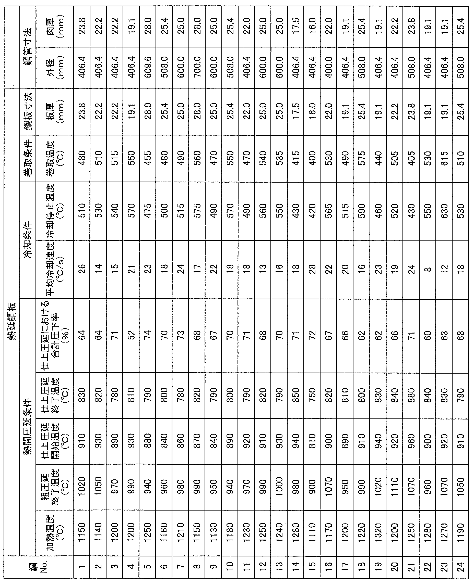
- the obtained slab was hot-rolled, cooled, and wound under the conditions shown in Table 2 to obtain a hot-rolled steel sheet for electric resistance pipes having a plate thickness (finished plate thickness) (mm) shown in Table 2.
- Test pieces were collected from the obtained hot-rolled steel sheet for electric resistance steel pipe and electric steel pipe, and the following solid solution N amount measurement, microstructure observation, tensile test, and Charpy impact test were carried out.
- the electric resistance steel pipe when the electric resistance welded portion was set to 0 ° in the cross section in the circumferential direction of the pipe, a test piece was collected from the base metal portion at a position 90 ° away from the electric resistance welded portion.
- the solid solution N amount was obtained by subtracting the N amount (precipitated N amount) existing as a precipitate from the total N amount in the steel.
- the amount of precipitated N was determined by an electrolytic extraction analysis method using a constant potential electrolysis method. In electrolytic extraction, an acetyl / acetone-based solution is used as the electrolytic solution and electrolyzed at a constant potential to dissolve only the base iron portion other than the precipitates such as carbides and nitrides, and the extracted residue is chemically analyzed. Then, the total amount of N in the residue was determined, and this was used as the amount of precipitated N.
- tissue observation The test piece for microstructure observation was taken from a hot-rolled steel sheet, polished so that the observation surface was at 1/2 of the sheet thickness t from the surface of the steel sheet and along the cross section in the rolling direction during hot rolling, and then nital corroded. Made.
- the tissue was observed and imaged at a plate thickness of 1 / 2t using an optical microscope (magnification: 1000x) or a scanning electron microscope (SEM, magnification: 1000x). From the obtained optical microscope image and SEM image, the area ratio of bainite and the balance (ferrite, pearlite, martensite, austenite) was determined. The area ratio of each tissue was calculated as the average value of the values obtained in each visual field by observing in 5 or more visual fields.
- the steel structure of the electrosewn steel pipe is the same as that of the hot-rolled steel sheet.
- the above-mentioned “plate thickness 1 / 2t position” and “plate thickness t 1/2 position” are “wall thickness 1 / 2t position” and “wall thickness t 1/2 position” in the case of electric resistance steel pipe. It shall point.
- ferrite is a product of diffusion transformation, and exhibits a structure with low dislocation density and almost recovery. This includes polygonal ferrite and pseudopolygonal ferrite.
- Bainite is a double-phase structure of lath-shaped ferrite and cementite with high dislocation density.
- the pearlite is an iron-carbide eutectoid structure (ferrite + cementite) or an iron-iron nitride eutectoid structure (ferrite + ⁇ '-Fe 4 N), in which ferrite and carbides or nitrides are arranged alternately. It presents with lamellar tissue.
- Martensite is a lath-like low-temperature transformation structure with a very high dislocation density.
- the SEM image shows a brighter contrast than ferrite and bainite.
- the area ratio of the tissue observed as martensite or austenite is measured from the obtained SEM image, and the measured value is measured by the method described later. The value obtained by subtracting the volume ratio of austenite was taken as the volume ratio of martensite.
- the volume fraction of austenite was measured by X-ray diffraction.
- the test piece for microstructure observation was prepared by grinding so that the diffraction surface was at a position of 1 / 2t of the plate thickness of the steel plate and the wall thickness of the steel pipe, and then performing chemical polishing of 50 ⁇ m or more to remove the surface processed layer. ..
- the K ⁇ ray of Mo was used for the measurement, and the volume fraction of austenite was obtained from the integrated intensities of the (200), (220) and (311) planes of fcc iron and the (200) and (211) planes of bcc iron.
- the average crystal grain size was measured using the SEM / EBSD method.
- the measurement area was 500 ⁇ m ⁇ 500 ⁇ m, and the measurement step size was 0.5 ⁇ m.
- the crystal grain size the orientation difference between adjacent crystal grains was determined, and the boundary where the orientation difference was 15 ° or more was measured as the crystal grain boundary.
- the arithmetic mean of the crystal grain size was obtained from the obtained grain boundaries and used as the average crystal grain size. In the crystal grain size analysis, those having a crystal grain size of less than 2.0 ⁇ m were excluded from the analysis target as measurement noise, and the obtained area fraction was assumed to be equal to the volume fraction.
- YR P (4.0FS / TS) ⁇ 100 ⁇ formula (1)
- "4.0FS” is the flow stress (MPa) at the nominal strain of 4.0%
- TS is the tensile strength (MPa) of the hot-rolled steel sheet.
- the longitudinal direction of the test piece is the rolling width direction or the pipe circumferential direction (rolling direction) from the obtained sheet thickness 1 / 2t position of the hot-rolled steel pipe for electric pipe and the wall thickness 1 / 2t position of the electric resistance pipe.
- a V-notch test piece was taken so as to be parallel to the longitudinal direction of the pipe). Then, it was carried out in accordance with the provisions of JIS Z 2242 (2018). The number of test pieces was 3 for each. The test was performed 3 times at each temperature and the average was calculated.
- the composition of the hot-rolled steel sheet for electric resistance steel pipe and the base material of the electric resistance pipe of the present invention is C: 0.030% or more and 0.20% or less, Si: 0.02% or more and 1.0%.
- Mn 0.40% or more and 3.0% or less
- P 0.050% or less
- S 0.020% or less
- N 0.0070% or more and 0.10% or less
- Al 0.005% It was 0.080% or less, N dissolved in the steel was 0.0010% or more and 0.090% or less, and the average crystal grain size of the steel structure at the 1 / 2t position was 20.0 ⁇ m or less. ..
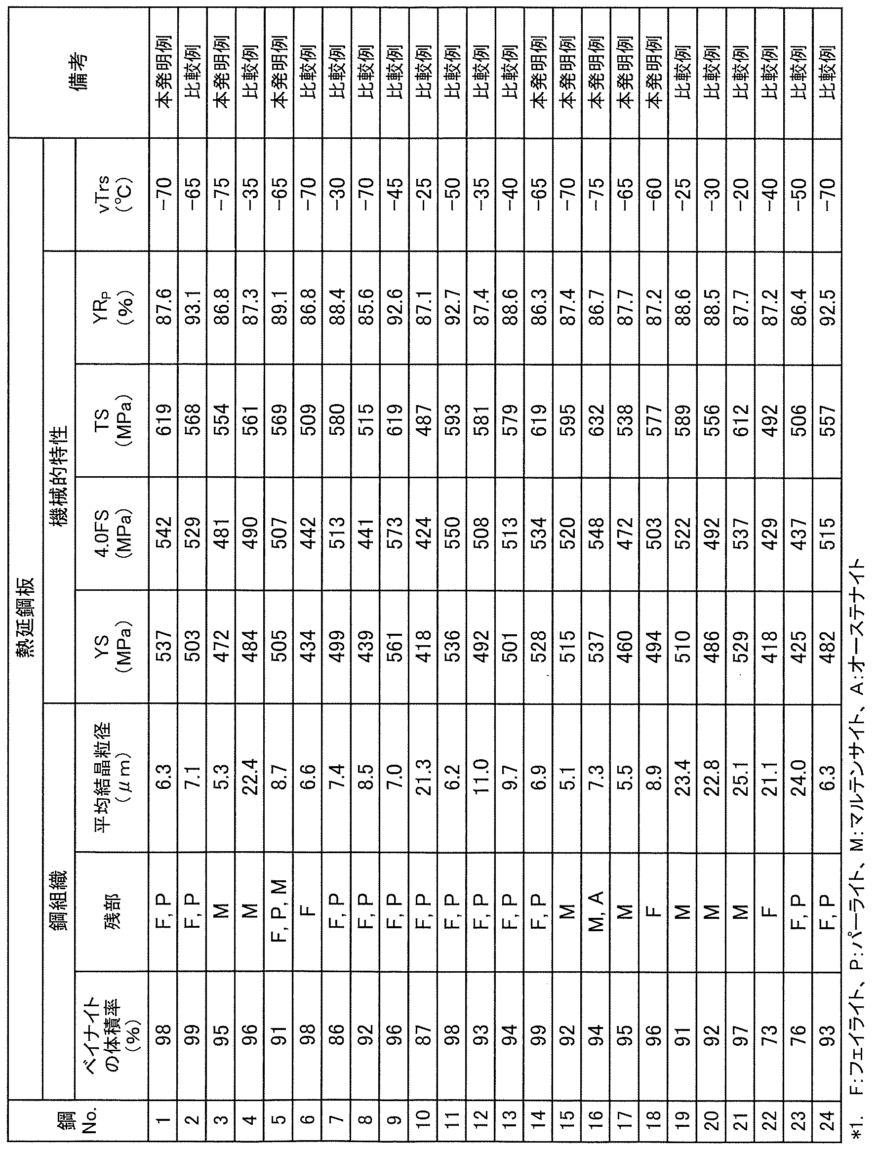
- all of the hot-rolled steel sheets for electric resistance welded steel pipes of the present invention have a yield stress of 450 MPa or more, a ductility-brittle transition temperature of -60 ° C or less in the Charpy impact test, and a yield ratio YR equivalent to that after pipe formation. P was 90.0% or less.
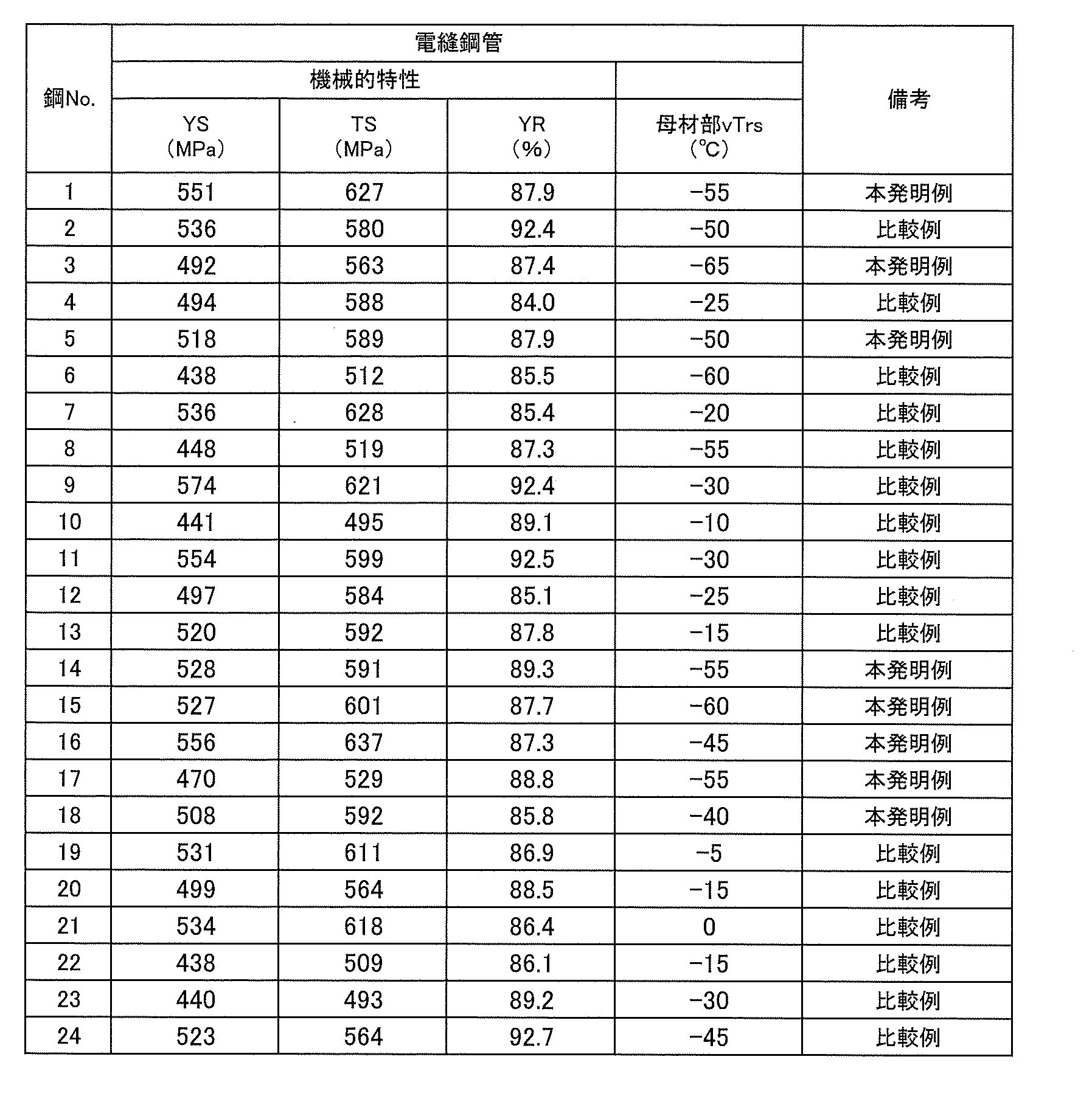
- all of the electrosewn steel pipes of the examples of the present invention had a yield stress of 450 MPa or more, a ductility-brittle transition temperature of ⁇ 40 ° C. or less in the Charpy impact test, and a yield ratio of 90.0% or less.
- the yield stress did not reach the desired value because the Mn content was below the range of the present invention. Further, since the crystal grains became coarse and the average crystal grain size exceeded the range of the present invention, the ductility-brittle transition temperature in the Charpy impact test did not reach the desired value.
- Base metal part 2 Welding heat affected zone 3 Melt solidification part
Landscapes
- Chemical & Material Sciences (AREA)
- Engineering & Computer Science (AREA)
- Mechanical Engineering (AREA)
- Materials Engineering (AREA)
- Metallurgy (AREA)
- Organic Chemistry (AREA)
- Physics & Mathematics (AREA)
- Thermal Sciences (AREA)
- Crystallography & Structural Chemistry (AREA)
- General Engineering & Computer Science (AREA)
- Manufacturing & Machinery (AREA)
- Heat Treatment Of Steel (AREA)
Abstract
Description
YRP=(4.0FS/TS)×100 ・・・式(1)
ただし、式(1)において、「4.0FS」は公称ひずみ4.0%における流動応力(MPa)であり、TSは熱延鋼板の引張強度(MPa)である。
なお、熱延鋼板および電縫鋼管の降伏強度および引張強度は、後述する実施例に記載の方法で求めた。また本発明において、公称ひずみは、引張試験において、伸び計により測定した試験片平行部の標点間距離の変位量を、引張前の標点間距離で除して100倍した値である。
[1] 成分組成は、質量%で、
C :0.030%以上0.20%以下、
Si:0.02%以上1.0%以下、
Mn:0.40%以上3.0%以下、
P :0.050%以下、
S :0.020%以下、
N :0.0070%以上0.10%以下、
Al:0.005%以上0.080%以下
を含有し、残部がFeおよび不可避的不純物からなり、
鋼中に固溶するNが0.0010%以上0.090%以下であり、
板厚をtとしたとき、1/2t位置における鋼組織は、平均結晶粒径が20.0μm以下である、電縫鋼管用熱延鋼板。
[2] 前記成分組成に加えてさらに、質量%で、
Nb:0.15%以下、
V :0.15%以下、
Ti:0.050%以下、
Cu:1.0%以下、
Ni:1.0%以下、
Cr:0.20%以下、
Mo:0.20%以下、
Ca:0.010%以下、
B :0.0050%以下
のうちから選ばれた1種または2種以上を含有する、上記[1]に記載の電縫鋼管用熱延鋼板。
[3] 前記1/2t位置における鋼組織は、体積率で、ベイナイトが90%以上であり、残部がフェライト、パーライト、マルテンサイト、オーステナイトから選択される1種または2種以上を有する、上記[1]または[2]に記載の電縫鋼管用熱延鋼板。
[4] 前記板厚が17mm超30mm以下である、上記[1]~[3]のいずれか1つに記載の電縫鋼管用熱延鋼板。
[5] 上記[1]~[4]のいずれか1つに記載の電縫鋼管用熱延鋼板の製造方法であって、
上記[1]または[2]に記載の成分組成を有する鋼素材を、
加熱温度:1100℃以上1300℃以下に加熱した後、
粗圧延終了温度:900℃以上1100℃以下、仕上圧延開始温度:800℃以上950℃以下、仕上圧延終了温度:750℃以上850℃以下、かつ、仕上圧延における合計圧下率:60%以上である熱間圧延を施し、
次いで、板厚中心温度における、平均冷却速度:10℃/s以上30℃/s以下、冷却停止温度:400℃以上600℃以下で冷却を施し、
次いで、400℃以上600℃以下の温度で巻取る、電縫鋼管用熱延鋼板の製造方法。
[6] 母材部と電縫溶接部を有する電縫鋼管であって、
前記母材部の成分組成は、質量%で、
C :0.030%以上0.20%以下、
Si:0.02%以上1.0%以下、
Mn:0.40%以上3.0%以下、
P :0.050%以下、
S :0.020%以下、
N :0.0070%以上0.10%以下、
Al:0.005%以上0.080%以下
を含有し、残部がFeおよび不可避的不純物からなり、
鋼中に固溶するNが0.0010%以上0.090%以下であり、
前記母材部の肉厚をtとしたとき、前記母材部の1/2t位置における鋼組織は、平均結晶粒径が20.0μm以下である、電縫鋼管。
[7] 前記母材部の前記成分組成に加えてさらに、質量%で、
Nb:0.15%以下、
V :0.15%以下、
Ti:0.050%以下
Cu:1.0%以下、
Ni:1.0%以下、
Cr:0.20%以下、
Mo:0.20%以下、
Ca:0.010%以下、
B :0.0050%以下
のうちから選ばれた1種または2種以上を含む、上記[6]に記載の電縫鋼管。
[8] 前記母材部の1/2t位置における前記鋼組織は、体積率で、ベイナイトが90%以上であり、
残部がフェライト、パーライト、マルテンサイト、オーステナイトから選択される1種または2種以上を有する、上記[6]または[7]に記載の電縫鋼管。
[9] 前記母材部の前記肉厚が、17mm超30mm以下である、上記[6]~[8]のいずれか1つに記載の電縫鋼管。
[10] 上記[1]または[2]に記載の熱延鋼板を冷間ロール成形により円筒状に成形してオープン管とし、該オープン管の周方向両端部を突合せて電縫溶接する、電縫鋼管の製造方法。
[11] 上記[1]または[2]に記載の成分組成を有する鋼素材を、
加熱温度:1100℃以上1300℃以下に加熱した後、
粗圧延終了温度:900℃以上1100℃以下、仕上圧延開始温度:800℃以上950℃以下、仕上圧延終了温度:750℃以上850℃以下、かつ、仕上圧延における合計圧下率:60%以上である熱間圧延を施し、
次いで、板厚中心温度における、平均冷却速度:10℃/s以上30℃/s以下、冷却停止温度:400℃以上600℃以下で冷却を施し、
次いで、400℃以上600℃以下の温度で巻取り熱延鋼板とし、
次いで、冷間ロール成形により前記熱延鋼板を円筒状に成形してオープン管とし、該オープン管の周方向両端部を突合せて電縫溶接する、電縫鋼管の製造方法。
[12] 上記[6]~[9]のいずれか1つに記載の電縫鋼管を用いた、ラインパイプ。
[13] 上記[6]~[9]のいずれか1つに記載の電縫鋼管を用いた、建築構造物。
Cは、固溶強化により鋼の強度を上昇させるとともに、転位に固着してその運動を抑制することで、変形中の転位の回復を阻害して、鋼の加工硬化能を向上させる元素である。本発明で目的とする強度および降伏比を得るためには、0.030%以上のCを含有することが必要である。しかし、C含有量が0.20%を超えると、硬質なパーライトおよびマルテンサイトの割合が高くなり靱性が低下する。このため、C含有量は0.030%以上0.20%以下とする。C含有量は、好ましくは0.035%以上であり、好ましくは0.19%以下である。より好ましくは0.040%以上であり、より好ましくは0.18%以下である。さらに好ましくは0.050%以上であり、さらに好ましくは0.15%以下である。
Siは、固溶強化により鋼の強度を上昇させる元素であり、必要に応じて含有することができる。このような効果を得るためには、0.02%以上のSiを含有することが望ましい。しかし、Si含有量が1.0%を超えると降伏比が高くなり、靱性が低下する。このため、Si含有量は1.0%以下とする。Si含有量は、好ましくは0.03%以上であり、好ましくは0.80%以下である。より好ましくは0.05%以上であり、より好ましくは0.50%以下である。さらに好ましくは0.15%以上であり、さらに好ましくは0.30%以下である。
Mnは、固溶強化により鋼の強度を上昇させる元素である。また、Mnはフェライト、ベイナイト、マルテンサイト変態開始温度を低下させることで組織の微細化に寄与する元素である。本発明で目的とする強度および靱性を得るためには、0.40%以上のMnを含有することが必要である。しかしながら、Mn含有量が3.0%を超えると降伏比が高くなり、靱性が低下する。このため、Mn含有量は0.40%以上3.0%以下とする。Mn含有量は、好ましくは0.50%以上であり、好ましくは2.5%以下である。より好ましくは0.60%以上であり、より好ましくは2.0%以下である。さらに好ましくは0.70%以上であり、さらに好ましくは1.7%以下である。
Pは、粒界に偏析し材料の不均質を招くため、不可避的不純物としてできるだけ低減することが好ましいが、0.050%以下の含有量までは許容できる。このため、P含有量は0.050%以下とする。P含有量は、好ましくは0.040%以下であり、より好ましくは0.030%以下である。なお、特にPの下限は規定しないが、過度の低減は製錬コストの高騰を招くため、Pは0.002%以上とすることが好ましい。
Sは、鋼中では通常、MnSとして存在するが、MnSは、熱間圧延で薄く延伸され、延性に悪影響を及ぼす。このため、本発明ではSをできるだけ低減することが好ましいが、0.020%以下の含有量までは許容できる。このため、S含有量は0.020%以下とする。S含有量は、好ましくは0.015%以下であり、より好ましくは0.010%以下である。なお、特にSの下限は規定しないが、過度の低減は製錬コストの高騰を招くため、Sは0.0002%以上とすることが好ましい。
Nは、固溶強化により鋼の強度を上昇させるとともに、転位に固着してその運動を抑制することで、変形中の転位の回復を阻害して、鋼の加工硬化能を向上させる元素である。本発明で目的とする強度および降伏比を得るためには、0.0070%以上のNを含有することが必要である。しかし、N含有量が0.10%を超えると、鉄と鉄窒化物の共析組織(フェライト+γ’-Fe4N)から成る硬質な組織の割合が高くなり、靱性が低下する。また、溶接時に溶融した鋼中で多量のN2ガスが発生し、溶接部にブローホールが形成されやすくなるため、溶接性、溶接部の強度および靱性が悪化する。このため、N含有量は0.0070%以上0.10%以下とする。N含有量は、好ましくは0.0080%以上であり、好ましくは0.090%以下である。より好ましくは0.0090%以上であり、より好ましくは0.080%以下である。さらに好ましくは0.010%以上であり、さらに好ましくは0.070%以下である。
Alは、強力な脱酸剤として作用する元素である。この効果を得るため、0.005%以上のAlを含有する。しかし、Al含有量が0.080%を超えると溶接性が悪化するとともに、アルミナ系介在物が多くなり、表面性状が悪化する。また溶接部の靱性も低下する。このため、Al含有量は0.005%以上0.080%以下とする。好ましくは0.007%以上であり、好ましくは0.070%以下である。より好ましくは0.009%以上であり、より好ましくは0.050%以下である。
Nb:0.15%以下
Nbは、鋼中で微細な炭化物、窒化物を形成することで鋼の強度向上に寄与し、また、熱間圧延中のオーステナイトの粗大化を抑制することで組織の微細化にも寄与する元素であり、必要に応じて含有できる。上記した効果を得るため、Nbを含有する場合は、0.005%以上のNbを含有することが好ましい。しかし、Nb含有量が0.15%を超えると降伏比が高くなり靱性が低下する恐れがある。このため、Nbを含有する場合は、Nb含有量は0.15%以下とすることが好ましい。好ましくは0.005%以上である。より好ましくは0.008%以上であり、より好ましくは0.13%以下である。更に好ましくは0.010%以上であり、更に好ましくは0.10%以下である。
Vは、鋼中で微細な炭化物、窒化物を形成することで鋼の強度向上に寄与する元素であり、必要に応じて含有できる。上記した効果を得るため、Vを含有する場合は、0.005%以上のVを含有することが好ましい。しかし、V含有量が0.15%を超えると降伏比が高くなり、靱性が低下する恐れがある。このため、Vを含有する場合は、V含有量は0.15%以下とすることが好ましい。好ましくは0.005%以上である。より好ましくは0.008%以上であり、より好ましくは0.13%以下である。更に好ましくは0.010%以上であり、更に好ましくは0.10%以下である。
Tiは、鋼中で微細な炭化物、窒化物を形成することで鋼の強度向上に寄与する元素であり、必要に応じて含有できる。上記した効果を得るため、Tiを含有する場合は、0.005%以上のTiを含有することが好ましい。しかし、TiはNとの親和性が高いため、Ti含有量が0.050%を超えると固溶N量が減少し、降伏比が高くなる恐れがある。このため、Tiを含有する場合は、Ti含有量は0.050%以下とすることが好ましい。好ましくは0.005%以上である。より好ましくは0.006%以上であり、より好ましくは0.030%以下である。更に好ましくは0.007%以上であり、更に好ましくは0.025%以下である。
Cu、Ni、Cr、Moは、固溶強化により鋼の強度を上昇させる元素であり、必要に応じて含有することができる。一方、過度の含有は、降伏比の上昇および靱性の低下を招く恐れがある。よって、Cu、Ni、Cr、Moを含有する場合は、それぞれCu:1.0%以下、Ni:1.0%以下、Cr:0.20%以下、Mo:0.20%以下とすることが好ましい。
Cuは、好ましくは0.01%以上であり、より好ましくは0.02%以上であり、更に好ましくは0.04%以上である。Cuは、より好ましくは0.9%以下であり、更に好ましくは0.8%以下である。
Niは、好ましくは0.01%以上であり、より好ましくは0.02%以上であり、更に好ましくは0.04%以上である。Niは、より好ましくは0.9%以下であり、更に好ましくは0.8%以下である。
Crは、好ましくは0.01%以上であり、より好ましくは0.02%以上であり、更に好ましくは0.04%以上である。Crは、より好ましくは0.18%以下であり、更に好ましくは0.15%以下である。
Moは、好ましくは0.01%以上であり、より好ましくは0.02%以上であり、更に好ましくは0.04%以上である。Moは、より好ましくは0.18%以下であり、更に好ましくは0.15%以下である。
Caは、熱間圧延で薄く延伸されるMnS等の硫化物を球状化することで鋼の靱性向上に寄与する元素であり、必要に応じて含有できる。上記した効果を得るため、Caを含有する場合は、0.0005%以上のCaを含有することが好ましい。しかし、Ca含有量が0.010%を超えると鋼中にCa酸化物クラスターが形成され、靱性が悪化する恐れがある。このため、Caを含有する場合は、Ca含有量は0.010%以下とすることが好ましい。好ましくは0.0005%以上である。より好ましくは0.0008%以上であり、より好ましくは0.0080%以下である。更に好ましくは0.0010%以上であり、更に好ましくは0.0060%以下である。
Bは、フェライト変態開始温度を低下させることで組織の微細化に寄与する元素であり、必要に応じて含有できる。上記した効果を得るため、Bを含有する場合は、0.0003%以上のBを含有することが好ましい。しかし、B含有量が0.0050%を超えると降伏比が上昇し、靱性が悪化する恐れがある。このため、Bを含有する場合は、B含有量は0.0050%以下とすることが好ましい。好ましくは0.0003%以上である。より好ましくは0.0005%以上であり、より好ましくは0.0030%以下である。更に好ましくは0.0008%以上であり、更に好ましくは0.0010%以下である。
本発明における平均結晶粒径とは、結晶方位差(隣り合う結晶の方位差)が15°以上の境界によって囲まれた領域を結晶粒としたとき、該結晶粒の平均円相当径である。ここで、円相当径(結晶粒径)とは、対象となる結晶粒と面積が等しい円の直径とする。結晶方位差が15°以上の境界は、大角粒界と呼ばれ、脆性破壊の抵抗となる。1/2t位置における鋼組織の平均結晶粒径を20.0μm以下とすることで、大角粒界の総面積を増加させ、これにより本発明で目的とする強度および靱性を得ることができる。1/2t位置における鋼組織の平均結晶粒径は、より好ましくは15.0μm以下である。
なお、1/2t位置における鋼組織の平均結晶粒径の下限は特に規定しない。平均結晶粒径が減少すると降伏比が上昇するため、低降伏比の観点から、2.0μm以上とすることが好ましい。より好ましくは4.0μm以上である。
ベイナイトは、フェライトよりも硬質であり、一方でパーライト、マルテンサイトおよびオーステナイトよりも軟質であり、靱性に優れた組織である。ベイナイトに硬度の異なる組織を混合させた場合、硬度差に起因する応力集中によって界面が破壊の起点となりやすく、靱性が低下する。このため、ベイナイトの体積率は、上記した1/2t位置における鋼組織全体に対して90%以上とすることが好ましい。より好ましくは93%以上であり、更に好ましくは95%以上である。
ベイナイト以外の残部組織は、フェライト、パーライト、マルテンサイト、オーステナイトから選択される1種または2種以上を有する。これらの各組織の体積率の合計が10%超えでは、ベイナイトとの硬度差に起因する応力集中が生じやすくなって界面が破壊の起点となり、靱性が低下する。そのため、残部組織は、各組織の合計の体積率が、上記した1/2t位置における鋼組織全体に対して10%以下とすることが好ましい。より好ましくは5%以下とする。
加熱温度が1100℃未満である場合、被圧延材の変形抵抗が大きくなり圧延が困難となる。一方、加熱温度が1300℃を超えると、オーステナイト粒が粗大化し、後の圧延(粗圧延、仕上圧延)において微細なオーステナイト粒が得られず、本発明で目的とする鋼組織の平均結晶粒径を確保することが困難となる。このため、加熱温度は、1100℃以上1300℃以下とする。より好ましくは1120℃以上であり、より好ましくは1280℃以下である。
粗圧延終了温度が900℃未満である場合、後の仕上圧延中に鋼板表面温度がフェライト変態開始温度以下になり、多量の加工フェライトが生成し、その結果、強度が低下し、降伏比が上昇する。一方、粗圧延終了温度が1100℃を超えると、オーステナイトが粗大化し、かつオーステナイト中に十分な変形帯が導入されないため、本発明で目的とする鋼組織の平均結晶粒径を得ることができなくなる。このため、粗圧延終了温度は、900℃以上1100℃以下とする。より好ましくは910℃以上であり、より好ましくは1000℃以下である。
仕上圧延開始温度が800℃未満である場合、仕上圧延中に鋼板表面温度がフェライト変態開始温度以下になり、多量の加工フェライトが生成する。その結果、強度が低下し、降伏比が上昇する。一方、仕上圧延開始温度が950℃を超えると、オーステナイトが粗大化し、かつオーステナイト中に十分な変形帯が導入されないため、本発明で目的とする鋼組織の平均結晶粒径を得ることができなくなる。このため、仕上圧延開始温度は、800℃以上950℃以下とする。より好ましくは820℃以上であり、より好ましくは930℃以下である。
仕上圧延終了温度が750℃未満である場合、仕上圧延中に鋼板表面温度がフェライト変態開始温度以下になり、多量の加工フェライトが生成し、その結果、強度が低下し、降伏比が上昇する。一方、仕上圧延終了温度が850℃を超えると、オーステナイトが粗大化し、かつオーステナイト中に十分な変形帯が導入されないため、本発明で目的とする鋼組織の平均結晶粒径を得ることができなくなる。このため、仕上圧延終了温度は、750℃以上850℃以下とする。より好ましくは770℃以上であり、より好ましくは830℃以下である。
仕上圧延における合計圧下率が60%未満である場合、オーステナイトが粗大化し、かつオーステナイト中に十分な変形帯が導入されないため、本発明で目的とする鋼組織の平均結晶粒径を得ることができなくなる。仕上圧延における合計圧下率は、好ましくは65%以上である。特に上限は規定しないが、80%を超えると圧下率の上昇に対する靱性向上の効果が小さくなり、設備負荷が増大するだけであるため、仕上圧延における合計圧下率は80%以下が好ましい。より好ましくは75%以下である。
熱延鋼板の板厚中心温度で、冷却開始から後述する冷却停止までの温度域における平均冷却速度が10℃/s未満では、ベイナイトの核生成頻度が低くなるため、本発明で目的とする鋼組織の平均結晶粒径を得ることができない。また、多量のフェライトが生成するため所望の降伏強度が得られない。一方で、平均冷却速度が30℃/sを超えると、多量のマルテンサイトが生成し、その結果、降伏比が上昇し、靱性が低下する。平均冷却速度は、10℃/s以上30℃/s以下とする。好ましくは15℃/s以上であり、好ましくは25℃/s以下である。
熱延鋼板の板厚中心温度における冷却停止温度が400℃未満では、多量のマルテンサイトが生成し、その結果、降伏比が上昇し、靱性が低下する。一方で、冷却停止温度が600℃を超えると、フェライトおよびベイナイトの核生成頻度が低くなるため、本発明で目的とする鋼組織の平均結晶粒径および所望の分率のベイナイトを得ることができなくなる。冷却停止温度は、400℃以上600℃以下とする。好ましくは450℃以上であり、好ましくは580℃以下である。
また、図1には、腐食後の上記断面の一部(電縫鋼管の溶接部近傍)を模式的に示す。図1に示すように、溶融凝固部は、母材部1および熱影響部2と異なる組織形態やコントラストを有する領域(溶融凝固部3)として視認できる。例えば、炭素鋼および低合金鋼の電縫鋼管の溶融凝固部は、ナイタールで腐食した上記断面において、光学顕微鏡で白く観察される領域として特定できる。また、炭素鋼および低合金鋼のUOE鋼管の溶融凝固部は、ナイタールで腐食した上記断面において、光学顕微鏡でセル状またはデンドライト状の凝固組織を含有する領域として特定できる。
固溶N量(質量%)は、鋼中の全N量から析出物として存在するN量(析出N量)を差し引いて求めた。なお、析出N量は定電位電解法を用いた電解抽出分析法により求めた。電解抽出においては、電解液としてアセチル・アセトン系溶液を用いて、定電位にて電解することで、炭化物、窒化物などの析出物以外の地鉄部分のみを溶解し、抽出した残渣を化学分析して、残渣中の総N量を求め、これを析出N量とした。
組織観察用の試験片は熱延鋼板から採取し、観察面が鋼板表面から板厚tの1/2位置において熱間圧延時の圧延方向断面に沿うように、研磨した後、ナイタール腐食して作製した。組織観察は、光学顕微鏡(倍率:1000倍)または走査型電子顕微鏡(SEM、倍率:1000倍)を用いて、板厚1/2t位置における組織を観察し、撮像した。得られた光学顕微鏡像およびSEM像から、ベイナイトおよび残部(フェライト、パーライト、マルテンサイト、オーステナイト)の面積率を求めた。各組織の面積率は、5視野以上で観察を行い、各視野で得られた値の平均値として算出した。ここでは、組織観察により得られた面積率を、各組織の体積率とした。なお、造管前後で鋼組織が変化しないとみなせるため、電縫鋼管の鋼組織は熱延鋼板の鋼組織と同様とした。上記した「板厚1/2t位置」および「板厚tの1/2位置」は、電縫鋼管の場合には「肉厚1/2t位置」および「肉厚tの1/2位置」を指すものとする。
なお、結晶粒径解析においては、結晶粒径が2.0μm未満のものは測定ノイズとして解析対象から除外し、得られた面積率が体積率と等しいとした。
引張試験は、電縫鋼管用熱延鋼板においては引張方向が圧延方向と平行になるように、電縫鋼管においては引張方向がL方向(管長手方向)となるように、JIS Z 2241(2011)の規定に準拠して、JIS5号の引張試験片をそれぞれ採取した。各引張試験片を用いて、引張試験を実施し、降伏強度YS、引張強度TSを測定した。ただし、降伏強度YSは、公称ひずみ0.5%における流動応力とした。
また、以下の式(1)で示される熱延鋼板の造管後相当の降伏比(YRP)(%)を算出した。
YRP=(4.0FS/TS)×100 ・・・式(1)
ただし、式(1)において、「4.0FS」は公称ひずみ4.0%における流動応力(MPa)であり、TSは熱延鋼板の引張強度(MPa)である。
また、電縫鋼管の母材部の降伏比(YR)(=(電縫鋼管の母材部の降伏強度/電縫鋼管の母材部の引張強度)×100)(%)を算出した。
シャルピー衝撃試験は、得られた電縫鋼管用熱延鋼板の板厚1/2t位置および電縫鋼管の肉厚1/2t位置から、試験片長手方向が圧延幅方向または管周方向(圧延方向または管長手方向と垂直)と平行になるように、Vノッチ試験片を採取した。そして、JIS Z 2242(2018)の規定に準拠して実施した。試験片の本数は各3本とした。試験は各温度で3回実施し、その平均を求めた。

2 溶接熱影響部
3 溶融凝固部
Claims (13)
- 成分組成は、質量%で、
C :0.030%以上0.20%以下、
Si:0.02%以上1.0%以下、
Mn:0.40%以上3.0%以下、
P :0.050%以下、
S :0.020%以下、
N :0.0070%以上0.10%以下、
Al:0.005%以上0.080%以下
を含有し、残部がFeおよび不可避的不純物からなり、
鋼中に固溶するNが0.0010%以上0.090%以下であり、
板厚をtとしたとき、1/2t位置における鋼組織は、平均結晶粒径が20.0μm以下である、電縫鋼管用熱延鋼板。 - 前記成分組成に加えてさらに、質量%で、
Nb:0.15%以下、
V :0.15%以下、
Ti:0.050%以下、
Cu:1.0%以下、
Ni:1.0%以下、
Cr:0.20%以下、
Mo:0.20%以下、
Ca:0.010%以下、
B :0.0050%以下
のうちから選ばれた1種または2種以上を含有する、請求項1に記載の電縫鋼管用熱延鋼板。 - 前記1/2t位置における鋼組織は、体積率で、ベイナイトが90%以上であり、
残部がフェライト、パーライト、マルテンサイト、オーステナイトから選択される1種または2種以上を有する、請求項1または2に記載の電縫鋼管用熱延鋼板。 - 前記板厚が17mm超30mm以下である、請求項1~3のいずれか1項に記載の電縫鋼管用熱延鋼板。
- 請求項1~4のいずれか1項に記載の電縫鋼管用熱延鋼板の製造方法であって、
請求項1または2に記載の成分組成を有する鋼素材を、
加熱温度:1100℃以上1300℃以下に加熱した後、
粗圧延終了温度:900℃以上1100℃以下、仕上圧延開始温度:800℃以上950℃以下、仕上圧延終了温度:750℃以上850℃以下、かつ、仕上圧延における合計圧下率:60%以上である熱間圧延を施し、
次いで、板厚中心温度における、平均冷却速度:10℃/s以上30℃/s以下、冷却停止温度:400℃以上600℃以下で冷却を施し、
次いで、400℃以上600℃以下の温度で巻取る、電縫鋼管用熱延鋼板の製造方法。 - 母材部と電縫溶接部を有する電縫鋼管であって、
前記母材部の成分組成は、質量%で、
C :0.030%以上0.20%以下、
Si:0.02%以上1.0%以下、
Mn:0.40%以上3.0%以下、
P :0.050%以下、
S :0.020%以下、
N :0.0070%以上0.10%以下、
Al:0.005%以上0.080%以下
を含有し、残部がFeおよび不可避的不純物からなり、
鋼中に固溶するNが0.0010%以上0.090%以下であり、
前記母材部の肉厚をtとしたとき、前記母材部の1/2t位置における鋼組織は、平均結晶粒径が20.0μm以下である、電縫鋼管。 - 前記母材部の前記成分組成に加えてさらに、質量%で、
Nb:0.15%以下、
V :0.15%以下、
Ti:0.050%以下
Cu:1.0%以下、
Ni:1.0%以下、
Cr:0.20%以下、
Mo:0.20%以下、
Ca:0.010%以下、
B :0.0050%以下
のうちから選ばれた1種または2種以上を含む、請求項6に記載の電縫鋼管。 - 前記母材部の1/2t位置における前記鋼組織は、体積率で、ベイナイトが90%以上であり、
残部がフェライト、パーライト、マルテンサイト、オーステナイトから選択される1種または2種以上を有する、請求項6または7に記載の電縫鋼管。 - 前記母材部の前記肉厚が、17mm超30mm以下である、請求項6~8のいずれか1項に記載の電縫鋼管。
- 請求項1または2に記載の熱延鋼板を冷間ロール成形により円筒状に成形してオープン管とし、該オープン管の周方向両端部を突合せて電縫溶接する、電縫鋼管の製造方法。
- 請求項1または2に記載の成分組成を有する鋼素材を、
加熱温度:1100℃以上1300℃以下に加熱した後、
粗圧延終了温度:900℃以上1100℃以下、仕上圧延開始温度:800℃以上950℃以下、仕上圧延終了温度:750℃以上850℃以下、かつ、仕上圧延における合計圧下率:60%以上である熱間圧延を施し、
次いで、板厚中心温度における、平均冷却速度:10℃/s以上30℃/s以下、冷却停止温度:400℃以上600℃以下で冷却を施し、
次いで、400℃以上600℃以下の温度で巻取り熱延鋼板とし、
次いで、冷間ロール成形により前記熱延鋼板を円筒状に成形してオープン管とし、該オープン管の周方向両端部を突合せて電縫溶接する、電縫鋼管の製造方法。 - 請求項6~9のいずれか1項に記載の電縫鋼管を用いた、ラインパイプ。
- 請求項6~9のいずれか1項に記載の電縫鋼管を用いた、建築構造物。
Priority Applications (6)
| Application Number | Priority Date | Filing Date | Title |
|---|---|---|---|
| US17/776,326 US12139780B2 (en) | 2019-11-20 | 2020-11-10 | Hot-rolled steel sheet for electric resistance welded steel pipe and method for manufacturing the same, electric resistance welded steel pipe and method for manufacturing the same, line pipe, and building structure |
| EP20891044.8A EP4029962A4 (en) | 2019-11-20 | 2020-11-10 | HOT ROLLED STEEL SHEET FOR ELECTRICAL STEEL PIPES AND METHOD FOR THEIR PRODUCTION, ELECTRICAL STEEL PIPES AND METHOD FOR THEIR PRODUCTION, LINE PIPES AND BUILDING STRUCTURE |
| JP2021512294A JP6973681B2 (ja) | 2019-11-20 | 2020-11-10 | 電縫鋼管用熱延鋼板およびその製造方法、電縫鋼管およびその製造方法、ラインパイプ、建築構造物 |
| CN202080078928.5A CN114729426B (zh) | 2019-11-20 | 2020-11-10 | 电阻焊钢管用热轧钢板及其制造方法、电阻焊钢管及其制造方法、管线管、建筑结构物 |
| CA3152893A CA3152893C (en) | 2019-11-20 | 2020-11-10 | HOT-ROLLED STEEL SHEET FOR ELECTRO-WELDED STEEL PIPE AND ITS PRODUCTION PROCESS, ELECTRO-WELDED STEEL PIPE AND ITS PRODUCTION PROCESS, PIPELINE AND BUILDING STRUCTURE |
| KR1020227016029A KR102727026B1 (ko) | 2019-11-20 | 2020-11-10 | 전봉 강관용 열연 강판 및 그의 제조 방법, 전봉 강관 및 그의 제조 방법, 라인 파이프, 건축 구조물 |
Applications Claiming Priority (2)
| Application Number | Priority Date | Filing Date | Title |
|---|---|---|---|
| JP2019-209233 | 2019-11-20 | ||
| JP2019209233 | 2019-11-20 |
Publications (1)
| Publication Number | Publication Date |
|---|---|
| WO2021100534A1 true WO2021100534A1 (ja) | 2021-05-27 |
Family
ID=75981235
Family Applications (1)
| Application Number | Title | Priority Date | Filing Date |
|---|---|---|---|
| PCT/JP2020/041808 Ceased WO2021100534A1 (ja) | 2019-11-20 | 2020-11-10 | 電縫鋼管用熱延鋼板およびその製造方法、電縫鋼管およびその製造方法、ラインパイプ、建築構造物 |
Country Status (8)
| Country | Link |
|---|---|
| US (1) | US12139780B2 (ja) |
| EP (1) | EP4029962A4 (ja) |
| JP (1) | JP6973681B2 (ja) |
| KR (1) | KR102727026B1 (ja) |
| CN (1) | CN114729426B (ja) |
| CA (1) | CA3152893C (ja) |
| TW (1) | TWI758956B (ja) |
| WO (1) | WO2021100534A1 (ja) |
Cited By (1)
| Publication number | Priority date | Publication date | Assignee | Title |
|---|---|---|---|---|
| JPWO2024100939A1 (ja) * | 2022-11-08 | 2024-05-16 |
Families Citing this family (2)
| Publication number | Priority date | Publication date | Assignee | Title |
|---|---|---|---|---|
| KR102928500B1 (ko) * | 2023-12-11 | 2026-02-20 | 현대제철 주식회사 | 고성능 봉강 및 그 제조 방법 |
| KR102928486B1 (ko) * | 2023-12-11 | 2026-02-20 | 현대제철 주식회사 | 고성능 봉강 및 그 제조 방법 |
Citations (5)
| Publication number | Priority date | Publication date | Assignee | Title |
|---|---|---|---|---|
| JP2001303196A (ja) * | 2000-04-27 | 2001-10-31 | Kawasaki Steel Corp | ハイドロフォーミング性に優れ、歪み時効性を有する構造用電縫鋼管およびその製造方法 |
| WO2013099192A1 (ja) * | 2011-12-27 | 2013-07-04 | Jfeスチール株式会社 | 高張力熱延鋼板及びその製造方法 |
| JP5293903B1 (ja) | 2011-08-23 | 2013-09-18 | 新日鐵住金株式会社 | 厚肉電縫鋼管及びその製造方法 |
| WO2016056216A1 (ja) * | 2014-10-07 | 2016-04-14 | Jfeスチール株式会社 | ラインパイプ用鋼板及びその製造方法とラインパイプ用鋼管 |
| WO2017130875A1 (ja) * | 2016-01-27 | 2017-08-03 | Jfeスチール株式会社 | 電縫鋼管用高強度熱延鋼板およびその製造方法 |
Family Cites Families (11)
| Publication number | Priority date | Publication date | Assignee | Title |
|---|---|---|---|---|
| JPS5293903U (ja) | 1976-01-09 | 1977-07-13 | ||
| CA2527117A1 (en) * | 2003-05-28 | 2004-12-09 | Sumitomo Metal Industries, Ltd. | A use of a steel pipe for embedding-expanding as an oil well and a method of embedding-expanding of oil well pipes |
| BR112012024757B1 (pt) * | 2010-06-02 | 2019-01-29 | Nippon Steel & Sumitomo Metal Corporation | tubo de aço sem costura para tubos de condução e método para fabricação do mesmo |
| JP6177551B2 (ja) * | 2013-03-15 | 2017-08-09 | 株式会社神戸製鋼所 | 絞り加工性と加工後の表面硬さに優れる熱延鋼板 |
| MX376915B (es) * | 2013-04-15 | 2025-03-07 | Jfe Steel Corp | Lamina de acero laminada en caliente de alta resistencia y metodo para la fabricacion de la misma. |
| EP3000905B1 (en) * | 2013-05-21 | 2019-10-30 | Nippon Steel Corporation | Hot-rolled steel sheet and manufacturing method thereof |
| JP5708723B2 (ja) * | 2013-07-09 | 2015-04-30 | Jfeスチール株式会社 | 低温破壊靭性に優れたラインパイプ用厚肉電縫鋼管およびその製造方法 |
| BR112016025118B1 (pt) | 2014-04-30 | 2021-02-17 | Jfe Steel Corporation | chapa de aço de alta resistência e método para fabricação da mesma |
| CA2966570A1 (en) * | 2014-11-27 | 2016-06-02 | Jfe Steel Corporation | Electric resistance welded steel pipe and manufacturing method therefor |
| EP3476960B1 (en) * | 2016-06-22 | 2020-10-21 | JFE Steel Corporation | Hot-rolled steel sheet for heavy-wall, high-strength line pipe, welded steel pipe for heavy-wall, high-strength line pipe, and method for producing the welded steel pipe |
| WO2018235244A1 (ja) * | 2017-06-22 | 2018-12-27 | 新日鐵住金株式会社 | ラインパイプ用アズロール電縫鋼管及び熱延鋼板 |
-
2020
- 2020-11-10 WO PCT/JP2020/041808 patent/WO2021100534A1/ja not_active Ceased
- 2020-11-10 JP JP2021512294A patent/JP6973681B2/ja active Active
- 2020-11-10 CA CA3152893A patent/CA3152893C/en active Active
- 2020-11-10 EP EP20891044.8A patent/EP4029962A4/en active Pending
- 2020-11-10 KR KR1020227016029A patent/KR102727026B1/ko active Active
- 2020-11-10 CN CN202080078928.5A patent/CN114729426B/zh active Active
- 2020-11-10 US US17/776,326 patent/US12139780B2/en active Active
- 2020-11-18 TW TW109140237A patent/TWI758956B/zh active
Patent Citations (5)
| Publication number | Priority date | Publication date | Assignee | Title |
|---|---|---|---|---|
| JP2001303196A (ja) * | 2000-04-27 | 2001-10-31 | Kawasaki Steel Corp | ハイドロフォーミング性に優れ、歪み時効性を有する構造用電縫鋼管およびその製造方法 |
| JP5293903B1 (ja) | 2011-08-23 | 2013-09-18 | 新日鐵住金株式会社 | 厚肉電縫鋼管及びその製造方法 |
| WO2013099192A1 (ja) * | 2011-12-27 | 2013-07-04 | Jfeスチール株式会社 | 高張力熱延鋼板及びその製造方法 |
| WO2016056216A1 (ja) * | 2014-10-07 | 2016-04-14 | Jfeスチール株式会社 | ラインパイプ用鋼板及びその製造方法とラインパイプ用鋼管 |
| WO2017130875A1 (ja) * | 2016-01-27 | 2017-08-03 | Jfeスチール株式会社 | 電縫鋼管用高強度熱延鋼板およびその製造方法 |
Non-Patent Citations (1)
| Title |
|---|
| See also references of EP4029962A4 |
Cited By (3)
| Publication number | Priority date | Publication date | Assignee | Title |
|---|---|---|---|---|
| JPWO2024100939A1 (ja) * | 2022-11-08 | 2024-05-16 | ||
| WO2024100939A1 (ja) * | 2022-11-08 | 2024-05-16 | Jfeスチール株式会社 | 熱延鋼板、電縫鋼管および角形鋼管ならびにラインパイプおよび建築構造物 |
| JP7700876B2 (ja) | 2022-11-08 | 2025-07-01 | Jfeスチール株式会社 | 熱延鋼板、電縫鋼管および角形鋼管ならびにラインパイプおよび建築構造物 |
Also Published As
| Publication number | Publication date |
|---|---|
| JP6973681B2 (ja) | 2021-12-01 |
| US20220396856A1 (en) | 2022-12-15 |
| TW202129024A (zh) | 2021-08-01 |
| EP4029962A4 (en) | 2022-09-21 |
| EP4029962A1 (en) | 2022-07-20 |
| JPWO2021100534A1 (ja) | 2021-12-02 |
| KR102727026B1 (ko) | 2024-11-05 |
| KR20220082041A (ko) | 2022-06-16 |
| CN114729426A (zh) | 2022-07-08 |
| CA3152893C (en) | 2024-11-05 |
| CA3152893A1 (en) | 2021-05-27 |
| TWI758956B (zh) | 2022-03-21 |
| CN114729426B (zh) | 2023-06-23 |
| US12139780B2 (en) | 2024-11-12 |
Similar Documents
| Publication | Publication Date | Title |
|---|---|---|
| EP3042976B1 (en) | Steel sheet for thick-walled high-strength line pipe having exceptional corrosion resistance, crush resistance properties, and low-temperature ductility, and line pipe | |
| JP7081727B1 (ja) | 電縫鋼管およびその製造方法 | |
| EP2520683B1 (en) | High strength steel sheet having excellent brittle crack resistance and method for manufacturing same | |
| KR20190084092A (ko) | 라인 파이프용 애즈롤 전봉 강관 | |
| JP6947333B2 (ja) | 電縫鋼管およびその製造方法ならびにラインパイプおよび建築構造物 | |
| JP7088417B2 (ja) | 電縫鋼管およびその製造方法 | |
| JP7211566B1 (ja) | 高強度熱延鋼板およびその製造方法、並びに高強度電縫鋼管およびその製造方法 | |
| JP7750338B2 (ja) | 熱延鋼板およびその製造方法 | |
| WO2021020220A1 (ja) | 耐サワーラインパイプ用高強度鋼板およびその製造方法並びに耐サワーラインパイプ用高強度鋼板を用いた高強度鋼管 | |
| JP6973681B2 (ja) | 電縫鋼管用熱延鋼板およびその製造方法、電縫鋼管およびその製造方法、ラインパイプ、建築構造物 | |
| JPWO2019180957A1 (ja) | 圧延h形鋼及びその製造方法 | |
| JP6390813B2 (ja) | 低温用h形鋼及びその製造方法 | |
| JP7207250B2 (ja) | 鋼材及びその製造方法 | |
| CN115362274A (zh) | 钢板及其制造方法 | |
| JP2022106590A (ja) | 電縫鋼管および電縫鋼管の製造方法 | |
| CA3159223C (en) | Electric resistance welded steel pipe, method for producing the same, line pipe, and building structure | |
| WO2021200572A1 (ja) | 母材靭性および継手靭性に優れた高張力鋼板とその製造方法 |
Legal Events
| Date | Code | Title | Description |
|---|---|---|---|
| ENP | Entry into the national phase |
Ref document number: 2021512294 Country of ref document: JP Kind code of ref document: A |
|
| 121 | Ep: the epo has been informed by wipo that ep was designated in this application |
Ref document number: 20891044 Country of ref document: EP Kind code of ref document: A1 |
|
| ENP | Entry into the national phase |
Ref document number: 3152893 Country of ref document: CA |
|
| ENP | Entry into the national phase |
Ref document number: 2020891044 Country of ref document: EP Effective date: 20220413 |
|
| ENP | Entry into the national phase |
Ref document number: 20227016029 Country of ref document: KR Kind code of ref document: A |
|
| NENP | Non-entry into the national phase |
Ref country code: DE |