WO2021100873A1 - エアフィルタ - Google Patents
エアフィルタ Download PDFInfo
- Publication number
- WO2021100873A1 WO2021100873A1 PCT/JP2020/043506 JP2020043506W WO2021100873A1 WO 2021100873 A1 WO2021100873 A1 WO 2021100873A1 JP 2020043506 W JP2020043506 W JP 2020043506W WO 2021100873 A1 WO2021100873 A1 WO 2021100873A1
- Authority
- WO
- WIPO (PCT)
- Prior art keywords
- frame
- filter
- sealing material
- air filter
- pleated
- Prior art date
- Legal status (The legal status is an assumption and is not a legal conclusion. Google has not performed a legal analysis and makes no representation as to the accuracy of the status listed.)
- Ceased
Links
Images




Classifications
-
- B—PERFORMING OPERATIONS; TRANSPORTING
- B01—PHYSICAL OR CHEMICAL PROCESSES OR APPARATUS IN GENERAL
- B01D—SEPARATION
- B01D46/00—Filters or filtering processes specially modified for separating dispersed particles from gases or vapours
- B01D46/52—Particle separators, e.g. dust precipitators, using filters embodying folded corrugated or wound sheet material
- B01D46/521—Particle separators, e.g. dust precipitators, using filters embodying folded corrugated or wound sheet material using folded, pleated material
-
- B—PERFORMING OPERATIONS; TRANSPORTING
- B01—PHYSICAL OR CHEMICAL PROCESSES OR APPARATUS IN GENERAL
- B01D—SEPARATION
- B01D46/00—Filters or filtering processes specially modified for separating dispersed particles from gases or vapours
- B01D46/52—Particle separators, e.g. dust precipitators, using filters embodying folded corrugated or wound sheet material
- B01D46/521—Particle separators, e.g. dust precipitators, using filters embodying folded corrugated or wound sheet material using folded, pleated material
- B01D46/523—Particle separators, e.g. dust precipitators, using filters embodying folded corrugated or wound sheet material using folded, pleated material with means for maintaining spacing between the pleats or folds
-
- B—PERFORMING OPERATIONS; TRANSPORTING
- B01—PHYSICAL OR CHEMICAL PROCESSES OR APPARATUS IN GENERAL
- B01D—SEPARATION
- B01D46/00—Filters or filtering processes specially modified for separating dispersed particles from gases or vapours
- B01D46/0002—Casings; Housings; Frame constructions
-
- B—PERFORMING OPERATIONS; TRANSPORTING
- B01—PHYSICAL OR CHEMICAL PROCESSES OR APPARATUS IN GENERAL
- B01D—SEPARATION
- B01D46/00—Filters or filtering processes specially modified for separating dispersed particles from gases or vapours
- B01D46/0084—Filters or filtering processes specially modified for separating dispersed particles from gases or vapours provided with safety means
- B01D46/0097—Special means for preventing bypass around the filter, i.e. in addition to usual seals
-
- F—MECHANICAL ENGINEERING; LIGHTING; HEATING; WEAPONS; BLASTING
- F16—ENGINEERING ELEMENTS AND UNITS; GENERAL MEASURES FOR PRODUCING AND MAINTAINING EFFECTIVE FUNCTIONING OF MACHINES OR INSTALLATIONS; THERMAL INSULATION IN GENERAL
- F16J—PISTONS; CYLINDERS; SEALINGS
- F16J15/00—Sealings
- F16J15/02—Sealings between relatively-stationary surfaces
- F16J15/14—Sealings between relatively-stationary surfaces by means of granular or plastic material, or fluid
-
- F—MECHANICAL ENGINEERING; LIGHTING; HEATING; WEAPONS; BLASTING
- F24—HEATING; RANGES; VENTILATING
- F24F—AIR-CONDITIONING; AIR-HUMIDIFICATION; VENTILATION; USE OF AIR CURRENTS FOR SCREENING
- F24F8/00—Treatment, e.g. purification, of air supplied to human living or working spaces otherwise than by heating, cooling, humidifying or drying
- F24F8/10—Treatment, e.g. purification, of air supplied to human living or working spaces otherwise than by heating, cooling, humidifying or drying by separation, e.g. by filtering
- F24F8/108—Treatment, e.g. purification, of air supplied to human living or working spaces otherwise than by heating, cooling, humidifying or drying by separation, e.g. by filtering using dry filter elements
-
- B—PERFORMING OPERATIONS; TRANSPORTING
- B01—PHYSICAL OR CHEMICAL PROCESSES OR APPARATUS IN GENERAL
- B01D—SEPARATION
- B01D2271/00—Sealings for filters specially adapted for separating dispersed particles from gases or vapours
- B01D2271/02—Gaskets, sealings
- B01D2271/022—Axial sealings
Definitions
- the present invention relates to an air filter.
- Patent Document 1 proposes a filter with ears. This eared filter prevents the occurrence of air leaks due to the gap between the filter and the filter frame.
- this filter with ears the ears joined to both ends of the filter are sandwiched and fixed between the filter frame and the pre-filter frame. As a result, no gap is generated between the filter and the filter frame, and the occurrence of air leakage is prevented.
- the filter with ears of Patent Document 1 is provided with ears along the direction along the crease of the filter. Therefore, although it is possible to prevent the occurrence of gaps on the left and right side surfaces on the upstream side of the filter frame, it is difficult to prevent air leaks generated from the corners that are the joints between the upper and lower frames of the filter frame and the left and right frames. there were.
- the present invention has been made in consideration of such circumstances, and an object of the present invention is to provide an air filter capable of preventing an air leak generated from a corner portion of a filter frame.
- the air filter according to the present invention is bent in a zigzag shape at a crease along the first direction and alternately appears along a second direction orthogonal to the first direction.
- a pleated filter medium having a portion and a valley portion, a pair of first frame members facing the second direction and extending along the first direction, and a pair of first frame members facing the first direction and facing the second direction.
- a rectangular filter frame having a pair of second frame members extending along the same direction, opening in the airflow direction orthogonal to the first direction and the second direction, and accommodating the pleated filter medium.
- a filter frame having an overlapping portion in which each end portion of each of the first frame materials in the first direction and each end portion of each of the second frame materials in the second direction overlap, and the filter frame. It is provided with at least the second frame material of the above and a cushioning material arranged between the pleated filter media and sandwiched between the overlapping portions.
- FIG. 2 is a cross-sectional view taken along the line III-III of FIG.
- FIG. 3 is a cross-sectional view showing an air filter as a modification corresponding to FIG.
- FIG. 3 is a cross-sectional view showing an air filter as another modification corresponding to FIG.
- FIG. 4 is a cross-sectional view of an air filter along the vertical direction for explaining another reinforcing plate corresponding to FIG.
- FIG. 8 is a cross-sectional view taken along the line IX-IX of FIG.
- FIG. 9 is a cross-sectional view of an air filter having another presser plate corresponding to FIG.
- FIG. 9 is a cross-sectional view of an air filter having another left and right sealing material corresponding to FIG.
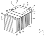
- FIG. 1 is a perspective view of the air filter 1 according to the present embodiment.
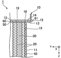
- FIG. 2 is a partial cross-sectional view of the air filter 1.
- FIG. 3 is a cross-sectional view taken along the line III-III of FIG.
- the X direction in FIGS. 1 to 11 is defined as the direction of the air flow.
- the Z direction is the downward direction, and the opposite direction of the Z direction is the upward direction.
- the Y direction is the left direction, and the opposite direction of the Y direction is the right direction.
- the air filter 1 has, for example, the performance of a HEPA (High Efficiency Particulate Air) filter.
- the HEPA filter is a filter having a collection efficiency of 99.97% or more with respect to particles having a particle size of 0.3 ⁇ m at a rated air volume, and an initial pressure loss of 245 Pa or less.
- the air filter 1 can be used for various purposes of purifying a gas at a high temperature.
- the air filter 1 is used, for example, for cleaning exhaust gas discharged from an incinerator, a drying furnace for drying parts handled in a semiconductor manufacturing process, and cleaning air in a sterilizing furnace for sterilizing medical instruments and the like.
- the air filter 1 is installed in, for example, an incinerator, a semiconductor manufacturing facility, a hospital, a research facility, or the like in the middle of an air flow path connected to each of the above furnaces.
- the air filter 1 includes a filter frame 10, a pleated filter medium 20, a reinforcing plate 30, a separator 40, a sealing material 50, and a cushioning material 60.
- the filter frame 10 is a rectangular frame member that opens in the airflow direction and accommodates the pleated filter medium 20.
- the filter frame 10 is formed by combining a pair of first frame members 11 and a pair of second frame members 12.
- the first frame member 11 faces the left-right direction (second direction) and has an end portion 13 in the up-down direction (first direction).
- the second frame member 12 faces in the vertical direction and has an end portion 14 in the horizontal direction.
- the filter frame 10 has four overlapping portions 15 on which each end portion 14 of each second frame material 12 overlaps with each end portion 13 of the first frame material 11, and the first frame material 11 And the second frame member 12 are combined. In the overlapping portion 15, the first frame member 11 and the second frame member 12 are in direct or indirect contact with each other.
- the first frame member 11 and the second frame member 12 are connected and fixed at the overlapping portion 15 by a connecting means such as a bolt to form the filter frame 10.
- the filter frame 10 is preferably formed of a heat-resistant material.
- the filter frame 10 is formed of, for example, a metal such as stainless steel, stainless steel (SUS304 or SUS430), aluminum, aluminum alloy, steel, or ceramic.
- the stainless steel may be plated with zinc or aluminum.
- the filter frame 10 may include a film formed by alumite treatment, chromate treatment or the like.
- the pleated filter medium 20 collects fine particles in the gas flowing in the airflow direction.
- the pleated filter medium 20 is formed by bending a sheet-shaped filter medium into a zigzag shape, and has peaks and valleys.
- the pleated filter medium 20 has a crease 21 along the vertical direction.
- the creases 21 form peaks and valleys that alternate along the left-right direction.
- the pleated filter medium 20 is arranged in the filter frame 10 so that the peaks and valleys appear on the upstream side and the downstream side of the air flow, respectively.
- the pleated filter medium 20 is, for example, a fiber body made of glass fiber, silica fiber, or a mixed fiber thereof.
- the pleated filter medium 20 has, for example, a non-woven fabric, paper, cotton, or matte form.
- the pleated filter medium 20 is made of glass non-woven fabric, glass filter paper, glass wool, or the like, which is made of glass fiber.
- the pleated filter medium 20 may include a binder that adheres the fibers to each other. Further, the pleated filter medium 20 may be sandwiched and supported between two heat-resistant breathable support members (for example, wire mesh).
- the reinforcing plate 30 is a substantially rectangular flat plate.
- the reinforcing plate 30 is inserted between the adjacent peaks of the pleated filter medium 20, that is, in the valley.
- the reinforcing plate 30 supports the vertical posture of other members such as the pleated filter medium 20. Specifically, the reinforcing plate 30 prevents deformation (bias, tilt, etc.) of the pleated filter medium 20 and the separator 40 due to heat, and deformation when a physical force is applied.
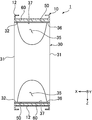
- FIG. 4 is a cross-sectional view of the air filter 1 along the vertical direction for explaining the reinforcing plate 30.
- the reinforcing plate 30 has a pair of edges 31 along the vertical direction and a pair of edges 32 along the airflow direction.
- the length of the pair of edges 31 along the vertical direction is substantially the same as the length of the pleated filter medium 20 in the vertical direction.
- the reinforcing plate 30 is inserted into at least a part of the valley portion of the pleated filter medium 20.
- the reinforcing plates 30 are arranged at required positions of the air filter 1, and a required number of reinforcing plates 30 are arranged.
- the reinforcing plate 30 has a thickness of, for example, 0.3 to 2.0 mm.
- the reinforcing plate 30 is made of, for example, metal. Since it is made of metal, the reinforcing plate 30 supports the weight of the sealing material 50 located in the upward direction and prevents the sealing material 50 from peeling off. It is preferable that the reinforcing plate 30 and the filter frame 10 have the same coefficient of thermal expansion (coefficient of linear thermal expansion, coefficient of linear expansion). Thereby, for example, damage to the sealing material 50 and the air filter 1 due to the influence of thermal expansion can be reduced.
- the air filter 1 when used in a high temperature region such as a sterilization furnace, the air filter 1 is exposed to a drastic temperature change during the shutdown and operation of the sterilization furnace. As this temperature change is repeated, the fibers of the sealing material 50 are scraped off, a gap is generated between the reinforcing plate 30 and the second frame material 12, and there is a possibility that a leak may occur.
- the air filter 1 has a notch 35 for the purpose of suppressing the occurrence of leakage even when used in a high temperature region.
- the notch 35 is formed on a pair of edges 32 along the airflow direction, and has a semicircular shape having the largest area from both ends of the pair of edges 32 along the airflow direction toward the center.
- the pair of edges 32 along the airflow direction have a contact portion 36 and a non-contact portion 37 with respect to the sealing material 50.
- the contact portions 36 are formed on both end sides of a pair of edges 32 along the air flow direction, and each has a width of 3 to 20 mm.
- the non-contact portion 37 is a portion other than the contact portion 36.
- the cutout portion 35 reduces the portion where the reinforcing plate 30 comes into contact with the sealing material 50.
- the reinforcing plate 30 When the notch 35 is not provided, the reinforcing plate 30 is considered to extend in the vertical direction and the airflow direction due to thermal expansion. If it is greatly extended in the vertical direction, the reinforcing plate 30 strongly pushes the sealing material 50, and the sealing material 50 is liable to crack. However, when the notch 35 is provided, the reinforcing plate 30 can diffuse in the extending direction due to thermal expansion and reduce the elongation in the vertical direction. As a result, it is possible to reduce the possibility that the reinforcing plate 30 thermally expands and pushes the sealing material 50, and it is possible to prevent the sealing material 50 from being damaged. Therefore, the reinforcing plate 30 suppresses the occurrence of cracks in the sealing material 50 even when a high temperature is repeatedly applied, and prevents the occurrence of leaks.
- the separator 40 is a spacing material between adjacent peaks (valleys) of the pleated filter media 20.
- the separator 40 is made of, for example, a metal such as aluminum or stainless steel.
- the separator 40 is preferably made of aluminum or an aluminum alloy.
- the separator 40 has a thickness of, for example, 25 to 65 ⁇ m.
- the separator 40 is formed by corrugating to bend it into a wavy shape.
- the separator 40 is inserted into the valley portion of the pleated filter medium 20 other than the valley portion into which the reinforcing plate 30 is inserted so that the crease is along the airflow direction.
- the separator 40 has a length in the vertical direction substantially the same as the length in the vertical direction of the pleated filter medium 20.
- the sealing material 50 (first and second sealing materials) is formed between at least a part of the inner surface 19 portion (the surface facing the inside of the air filter 1) of the filter frame 10 and the portion of the pleated filter medium 20 facing this portion. Seal.
- the sealing material 50 seals between each second frame material 12 and the pleated filter material 20.
- the pleated filter media 20 can come into surface contact with each of the first frame materials 11 by being pressed by the separator 40, whereas the pleated filter media 20 can make line contact with each of the second frame materials 12 and cannot make surface contact with each other.
- the sealing material 50 is preferably provided between each second frame member 12 and the pleated filter medium 20. Since the air filter 1 has the sealing material 50, a higher leak prevention effect can be obtained as compared with the case where only the cushioning material 60 is arranged between the filter frame 10 and the pleated filter material 20.
- the linear thermal expansion of the filter frame 10 is prevented in order to prevent the sealing material 50 from being damaged due to the difference in the amount of thermal expansion from the filter frame 10.
- the sealing material 50 is formed from a ceramic material adjusted to have the same coefficient of linear thermal expansion as the coefficient.
- the degree of freedom in selecting the material of the sealing material 50 is limited. Further, even if the materials have the same coefficient of linear expansion in a certain temperature range, the coefficient of linear thermal expansion may differ in another temperature range, and in the end, the occurrence of the difference in the amount of thermal expansion may not be suppressed.
- the sealing material 50 when a ceramic material having a linear expansion coefficient different from that of the filter frame 10 is used as the sealing material 50, cracks appear on the surface of the sealing material 50 when the air filter 1 is used at a high temperature, and cracks appear from the cracked portion.
- the fine particles of the sealing material 50 may come off and flow to the downstream side.
- a sealing material made of a ceramic material is generally obtained by applying a paste-like ceramic material to a filter medium and sintering it.
- the present inventor has determined that cracking of the sealing material occurs during sintering of the ceramic material, which causes dust generation from the ceramic material during use. Then, it was found that the sealing material 50 can suppress dust generation from the sealing material by being made of the following materials.
- It consists of a ceramic material that is 10-200%.
- the ceramic material include materials containing silica, alumina, zirconia and the like. Further, from the viewpoint of not containing a carcinogen, it is desirable that the ceramic material does not contain crystalline silica (for example, cristobalite).
- the sealing material 50 is formed by, for example, sintering a paste-like or liquid ceramic material.
- a sealing material 50 may have cracks inside when the ceramic material is sintered.
- the crack itself has the effect of relaxing the stress inside the sealing material 50 and suppressing the occurrence of new cracks during use. If the cracks do not reach the surface of the sealing material 50, dust generation during use does not occur. Therefore, even if such cracks are inherent in the sealing material 50, the air filter 1 can be used.
- the ceramic material of the sealing material 50 is made by sintering a paste-like ceramic material containing non-crystalline silica and alumina and having a viscosity at room temperature (23 ° C.) of 20,000 to 50,000 mPa ⁇ s. Is preferable.
- Crystalline silica (crystalline silica) is silica having a crystalline structure of SiO 2.
- Non-crystalline silica (amorphous silica) is silica that does not have a SiO 2 crystal structure. Since such a ceramic material does not contain crystalline silica but contains amorphous silica or alumina, the coefficient of thermal expansion of the sealing material 50 can be easily adjusted.
- the sintered sealing material 50 may have uneven thickness or holes. Can be suppressed from becoming empty.
- the entire component of the paste-like ceramic material excluding water preferably contains 50% by mass or more of amorphous silica and alumina.
- the viscosity at room temperature is preferably 25,000 to 45,000 mPa ⁇ s.
- the temperature range of 200 to 500 ° C. is the temperature range of the atmosphere in which the air filter 1 can be used.
- the temperature range is preferably 300 to 400 ° C.
- the ambient temperature during use of the air filter 1 may be such that the maximum temperature is within the above temperature range, and may be less than 200 ° C., for example, at the start of use.
- the ratio of the linear expansion coefficient of the sealing material 50 to the linear expansion coefficient of the filter frame 10 described above is calculated using the linear expansion coefficient of the filter frame 10 and the sealing material 50 at the same temperature within the above temperature range. In the present embodiment, when the ratio is 10 to 200%, the degree of freedom in selecting the combination of the filter frame 10 and the sealing material 50 is high.
- the above ratio exceeds 200%, thermal expansion along the filter frame 10 of the sealing material 50 (in the left-right direction which is the longitudinal direction of the sealing material 50) is regulated by each first frame material 11, and the compressive stress becomes large. There is a risk of damage. If the above ratio is less than 10%, the amount of thermal expansion of the filter frame 10 is too large, and even if the cushioning material 60 is provided, the sealing material 50 is pulled, and cracks inherent in the sealing material 50 develop. May appear on the surface of the sealing material 50. If cracks are present on the surface of the sealing material 50, the fine particles of the sealing material 50 are separated from the wall surface of the cracked sealing material 50 during use of the air filter 1, and the downstream side that has passed through the air filter 1 is separated. The gas is polluted.
- the above ratio is preferably 50 to 150%.
- the coefficient of linear expansion of the sealing material 50 may be larger than the coefficient of linear expansion of the filter frame 10, equal to the coefficient of linear expansion of the filter frame 10, or smaller than the coefficient of linear expansion of the filter frame 10. If it is larger than the coefficient of linear expansion of the filter frame 10, the thermal expansion of the sealing material 50 in the longitudinal direction (left-right direction) is regulated by each first frame material 11 with an appropriate force, so that the sealing material 50 cracks. It becomes difficult to progress. Therefore, the coefficient of linear expansion of the sealing material 50 is preferably larger than the coefficient of linear expansion of the filter frame 10.
- the degree of freedom in selecting the combination of the filter frame 10 and the sealing material 50 is high, the difference in the amount of thermal expansion between the two may become large depending on the combination of the selected filter frame 10 and the sealing material 50.
- the sealing material 50 can expand or contract relative to the filter frame 10, the growth of cracks inherent in the sealing material 50 is suppressed. As a result, dust generation is effectively suppressed.
- the coefficient of linear expansion of the sealing material 50 is 10% or more and less than 90% of the coefficient of linear expansion of the filter frame 10 in the temperature range of 200 to 500 ° C.
- the coefficient of linear expansion of the sealing material 50 is smaller than the coefficient of linear expansion of the filter frame 10
- the thermal expansion of the sealing material 50 in the longitudinal direction is appropriately regulated by the first frame material 11 to suppress the growth of cracks. It is disadvantageous in that it is difficult to obtain the desired effect.
- the cushioning material 60 is interposed between the sealing material 50 and the filter frame 10 as described above, the thermal expansion of the sealing material 50 is not regulated by the first frame material 11. However, the effect of suppressing the growth of cracks can be obtained.
- stainless steel has a higher coefficient of linear expansion in a high temperature region than in a low temperature region, and the amount of thermal expansion of the filter frame 10 when the air filter 1 is used is compared with that in sintering. large. Therefore, when the sealing material 50 is in contact with the filter frame 10, the sealing material 50 is greatly pulled by the filter frame 10, cracks of the sealing material 50 easily progress, and dust is easily generated.
- various ceramic materials having a coefficient of linear expansion smaller than that of stainless steel can be selected as the sealing material 50, and even in such a case, It is possible to suppress the progress of cracking of the sealing material 50 and suppress dust generation.
- the cushioning material 60 is arranged between the second frame material 12 of the filter frame 10 and the sealing material 50 (pleated filter material 20).
- the cushioning material 60 maintains a sealing property between the pleated filter medium 20 and the filter frame 10 by following the expansion or contraction of the cushioning material 60.
- the expansion or contraction of the filter frame 10 means expansion or contraction in a direction parallel to the surface direction of the filter frame 10 facing the sealing material 50.
- the cushioning material 60 is arranged between the sealing material 50 and the second frame material 12, the sealing material 50 is not restrained by the filter frame 10 during the use of the air filter 1. Alternatively, it can be expanded or contracted without being pulled by the filter frame 10.
- the cushioning material 60 has an end portion 61 in the left-right direction.
- the end portion 61 extends to the overlapping portion 15 and is sandwiched between the first frame member 11 and the second frame member 12.
- the cushioning material 60 preferably has cushioning properties and heat resistance, and is preferably made of, for example, a fibrous material. Since the cushioning material 60 made of a fibrous material easily expands and contracts, the effect of allowing expansion or contraction of the sealing material 50 along the filter frame 10 (also referred to as cushioning action) is great. Further, since the cushioning material 60 made of a fibrous material does not adhere to the filter frame 10, slipperiness with respect to the filter frame 10 is ensured. Further, by arranging the cushioning material 60 in a compressed state between the sealing material 50 and the filter frame 10, the sealing property between the sealing material 50 and the filter frame 10 can be obtained by the repulsive force of the fibrous material.
- the fibrous material consists of, for example, glass, ceramics and minerals.
- the cushioning material 60 made of a fibrous material can shrink together with the sealing material 50 when the sealing material 50 is sintered, the effect of suppressing the occurrence of cracks in the sealing material 50 during sintering can also be obtained.
- the sealing material 50 is sintered, the sealing material 50 shrinks while the filter frame 10 expands. Therefore, it is effective when the cushioning material 60 is interposed between the sealing material 50 and the filter frame 10 at the time of sintering.
- Ceramic is a material containing, for example, silica, alumina, zirconia and the like. If the cushioning material 60 contains a binder, it may melt or decompose during use and flow to the downstream side. Therefore, it is preferable that the cushioning material 60 does not contain a binder.
- the average fiber diameter of the fibers constituting the fibrous material is, for example, 0.01 to 10 ⁇ m.
- the form of the cushioning material 60 is, for example, cotton-like or sponge-like (porous). Examples of the preferable cushioning material 60 include glass wool and rock wool.
- Another member is not arranged between the cushioning material 60 and the sealing material 50.
- Another member is, for example, a sheet-like fiber body such as filter paper or non-woven fabric. If such a member is interposed between the cushioning material 60 and the sealing material 50, the effect of suppressing the occurrence of cracks during sintering of the sealing material 50 may be weakened.
- the air filter 1 particularly includes a step of forming the sealing material 50 and a step of arranging the cushioning material 60.
- the step of forming the sealing material 50 and the step of arranging the cushioning material 60 can be performed, for example, as described in (1) or (2) below.
- a cushioning material 60 is arranged on the upper surface (inner surface 19) of the second frame material 12 on the lower side of the filter frame 10, and a paste-like sealing material 50 is applied to the arranged cushioning material 60. Further, the pleated filter medium 20 and the separator 40 are attached to the coated sealing material 50. At this time, it is preferable that the first frame member 11 is joined to the lower second frame member 12. Next, another cushioning material 60 is arranged on the upper second frame member 12 with the inner surface 19 facing the lower second frame member 12 facing upward at the time of use. Then, the paste-like sealing material 50 is applied to the arranged cushioning material 60. The pleated filter medium 20 and the upper end portion of the separator 40 are attached to the coated sealing material 50. At this time, the first frame member 11 and the upper second frame member 12 are joined. Next, the obtained unfired air filter 1 is placed in a furnace, for example, and the sealing material 50 is sintered.
- a paste-like sealing material 50 is applied to a portion (lower end portion) of the pleated filter medium 20 and the separator 40 facing the second frame member 12 on the lower side of the filter frame 10.
- the cushioning material 60 is placed on the coated sealing material 50, and the lower second frame material 12 is placed on the cushioning material 60. This is turned upside down, and the paste-like sealing material 50 is applied to the portion (upper end portion) of the pleated filter medium 20 and the separator 40 facing the upper second frame member 12.
- Another cushioning material 60 is placed on the coated sealing material 50, and the upper second frame material 12 is placed on the cushioning material 60. It is preferable that the first frame member 11 is joined to the upper second frame member 12.
- the obtained unfired air filter 1 is placed in a furnace, for example, and the sealing material 50 is sintered.
- the cushioning material 60 is preferably arranged along the entire inner surface 19 of the second frame material 12, for example.
- the sealing material 50 preferably has a size that does not protrude from the cushioning material 60.
- the paste-like or liquid sealing material 50 may be naturally dried, but it is preferable to sinter at a high temperature. Sintering is performed, for example, in a dry atmosphere at 100-200 ° C. At this time, in order to suppress the occurrence of cracks in the sealing material 50, it is preferable to raise the temperature to the sintering temperature at a heating rate of 3 to 16 ° C./min.
- the paste-like sealing material 50 preferably does not contain crystalline silica, contains amorphous silica and alumina, and has a viscosity at room temperature (23 ° C.) of 20,000 to 50,000 mPa ⁇ s.
- the thickness of the sealing material 50 is preferably 3 to 20 mm.
- the thickness of the sealing material 50 is preferably 5 to 15 mm.
- the thickness of the sealing material 50 means the thickness in a dry state (state after sintering). It was found that the thinner the sealing material 50, the more likely it is that cracks will occur during sintering. A large internal stress is generated in the sealing material 50 due to the shrinkage of the sealing material 50 when water is released from the sealing material 50 during sintering, but it is considered that the thin sealing material 50 cannot withstand the size. Be done. On the other hand, if the thickness of the sealing material 50 is too thick, the weight of the air filter 1 cannot be reduced.
- the thickness of the cushioning material 60 is preferably 1 to 15 mm.
- the thickness of the cushioning material 60 is particularly preferably 3 to 10 mm.
- the cushioning material 60 expands and contracts in a direction (vertical direction) orthogonal to the direction along the filter frame 10. Therefore, when the cushioning material 60 receives a force from each of the pleated filter medium 20 and the separator 40, the cracks inherent in the sealing material 50 grow in the vertical direction and easily reach the surface of the sealing material 50. Therefore, the sealing material 50 is likely to generate dust. In particular, when the sealing material 50 is thick, the wall surface of the cracked sealing material 50 is large, so that the number of dust generation points increases.
- the sealing material 50 moves downward so as to further compress the cushioning material 60 with the filter frame 10 due to its own weight. Therefore, there may be a gap between the cushioning material 60 facing the upper second frame material 12 and the upper second frame material 12 on the opposite side, and a leak may occur. This problem becomes remarkable especially when the sealing material 50 is thick. From these viewpoints, the ratio of the thickness of the sealing material 50 to the thickness of the cushioning material 60 is preferably 1 or more, and more preferably 1.2 or more.
- the sealing material 50 may locally reach the filter frame 10 and come into contact with the filter frame 10 when the paste-like sealing material 50 is applied. Therefore, the cushioning action of the cushioning material 60 is limited, and there is a possibility that the progress of cracking of the sealing material 50 cannot be sufficiently suppressed. Further, if the thickness of the cushioning material 60 is too thin, the repulsive force when compressed between the sealing material 50 and the filter frame 10 is weak, and there is a gap between the sealing material 50 and the filter frame 10 to leak. May be done. From these viewpoints, the above ratio is preferably 5 or less, and more preferably 3 or less.
- the thickness of the cushioning material 60 is the thickness measured at a plurality of positions (three or more points) along the longitudinal direction (horizontal direction) with the cushioning material 60 arranged between the sealing material 50 and the filter frame 10. The average value.
- the thickness of the cushioning material 60 can be measured using, for example, a caliper.
- the filter frame 10 has a corner portion 16 formed by the overlapping portion 15.
- the corner portion 16 is formed on the inner surface 19 side of the filter frame 10, and is a portion where the first frame member 11 and the second frame member 12 intersect at right angles.
- the pleated filter medium 20 is airtightly arranged with respect to the filter frame 10 via the cushioning material 60 and the sealing material 50.
- a gap may be formed between the corner portion 16 and the cushioning material 60 or the sealing material 50, and an air leak may occur from the corner portion 16.
- air leakage may occur.
- the cushioning material 60 extends to the overlapping portion 15 and is sandwiched between the first frame material 11 and the second frame material 12.
- the cushioning material 60 can suitably prevent the formation of this gap, and air leakage can be suppressed.
- the air filter 1 can suppress a reduction in local collection efficiency at the corner portion 16.
- the dimensions of the cushioning material 60 provided for cushioning are only changed without using a separate configuration, air leakage at the corner portion 16 can be easily prevented without increasing the number of parts of the air filter 1. it can.
- the cushioning material 60 may be provided between the pleated filter medium 20 and the first frame member 11, or between the pleated filter medium 20 and the first frame member 11 and the second frame member 12. It may be provided in. Further, the cushioning material 60 may play the function of the sealing material 50.
- the sealing material 50 may be made of, for example, geopolymer, glass cotton, or urethane, in addition to the ceramic material.
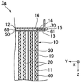
- FIG. 5 is a cross-sectional view showing an air filter 1a as a modification corresponding to FIG.
- the same reference numerals are given to the configurations and parts corresponding to the air filter 1, and duplicate description will be omitted.
- a filler 70 is further arranged in the overlapping portion 15. That is, the filler 70 is sandwiched between the first frame member 11 and the second frame member 12 in the overlapping portion 15, and fills the gap between the overlapping portions 15.
- the filler 70 is made of a material capable of filling the gaps in the overlapping portion 15, and is made of, for example, a filter paper similar to the pleated filter medium 20, a long fiber sintered body, or a foam.
- the filler 70 is arranged between the cushioning material 60 and the second frame material 12.
- the filler 70 may be arranged between the separator 40 and the first frame member 11. It is preferable that the filler 70 is arranged on the insertion side of the bolt that fastens the first frame member 11 and the first frame member 11 at the overlapping portion 15 with respect to the cushioning material 60.
- the fibers of the cushioning material 60 may be entangled with the bolt, which may hinder the fastening and removal of the bolt.
- the filler 70 presses the fibers of the cushioning material 60 so that the fibers of the cushioning material 60 entwined with the bolts do not come out together with the bolts when the bolts are removed.
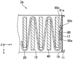
- FIG. 6 is a cross-sectional view showing an air filter 1b as another modification corresponding to FIG.
- the end portion 61b of the cushioning material 60b was bent along the shape of the inner surface 19 of the filter frame 10 in order to further reduce the air leak.
- the cushioning material 60b has a corner portion 62 formed by bending the end portion 61b downward or upward along the air flow direction. Since the cushioning material 60b has cushioning properties, when the first frame material 11 and the second frame material 12 are assembled so as to form an overlapping portion 15, they are crushed and a part of the corner portion 62 is crushed to form the overlapping portion 15. It is sandwiched between.
- the cushioning material 60b reliably covers the gap between the corner portion 16 and the pleated filter medium 20 and the sealing material 50, and air leakage generated from the corner portion 16 can be further suppressed.
- a filler 70 is arranged in the overlapping portion 15.
- the notch portion 35 is formed in a semicircular shape and the contact portion 36 is formed on a pair of edges 32 along the airflow direction has been described, but the shape of the notch portion 35 is not particularly limited.
- a plurality of notches 35 may be provided along a pair of edges 32 along the airflow direction, or may have a rectangular shape or a polygonal shape other than a semicircular shape.
- FIG. 7 is a cross-sectional view of the air filter 1c along the vertical direction for explaining another reinforcing plate 30c corresponding to FIG.
- the same reference numerals are given to the configurations and parts corresponding to the air filter 1, and duplicate description will be omitted.
- the reinforcing plate 30c has a substantially rectangular notch portion 35c, and a contact portion 36c and a non-contact portion 37c are formed on a pair of edges 32 along the airflow direction.
- a contact portion 36c and a non-contact portion 37c are formed on a pair of edges 32 along the airflow direction.
- the straight portion forming the peripheral edge of the notch portion is considered to be thermally expanded in the direction orthogonal to this linear direction, and the curved portion is considered to be thermally expanded in the centrifugal direction.
- the reinforcing plate thermally expands in the centrifugal direction (that is, the direction not along the vertical direction) from the cutout portion, so that the sealing material 50 is vertically expanded.
- the pushing force is thought to disperse and decrease. As a result, it is possible to prevent the sealing material 50 from being damaged when the reinforcing plate has a semicircular notch 35 having no portion orthogonal to the vertical direction.
- the pleated filter medium 20 is pressed by the separator 40 and comes into surface contact with each of the first frame members 11 at the ends in the left-right direction.
- a board may be provided.
- FIG. 8 is an explanatory view of the air filter 1d having the holding plate 90.
- FIG. 9 is a cross-sectional view taken along the line IX-IX of FIG. In FIG. 8, for the sake of explanation, a part of the first frame member 11 and the second frame member 12 is not shown. Further, the same reference numerals are given to the configurations and parts corresponding to the air filter 1, and duplicate description will be omitted.
- the air filter 1d further has a left and right sealing material 80 and a holding plate 90 as compared with the air filter 1.
- the left and right sealing material 80 (third sealing material) is between the portion on the inner surface 19 of each first frame member 11 and the end portion 17 in the left-right direction, which is the portion of the pleated filter medium 20 facing the portion on the inner surface 19.
- the left and right sealing material 80 is made of, for example, the same material as the sealing material 50 or glass fiber.
- the presser plate 90 compresses and holds the end portion 17 of the pleated filter medium 20 and the left and right sealing materials 80, and brings these into close contact with the first frame member 11.
- the presser plate 90 is made of a thin metal plate such as stainless steel that is bent so as to have an L shape when viewed in the vertical direction.
- the pressing plate 90 has a rising portion 91 and a pressing portion 95.
- the rising portion 91 is arranged perpendicular to the inner surface 19 of the first frame member 11.
- the rising portion 91 is arranged so as to be orthogonal to the air flow direction so as to cover the boundary between the left and right sealing material 80 and the end portion 17 when viewed from the upstream side.
- the rising portion 91 has a vertical length substantially the same as the vertical length of the pleated filter medium 20.
- the rising portion 91 has a left-right direction length smaller than the thickness (left-right direction length) of the left-right sealing material 80 and the pleated filter material 20 when no load is applied.
- the pressing portion 95 is formed by being bent toward the downstream side substantially orthogonally to the rising portion 91 from the end portion 92 located away from the first frame member 11 among the left and right end portions of the rising portion 91. It is the part to be done.
- the pressing portion 95 is inserted between the end portion 17 and the separator 40 arranged in the valley portion formed by the pleated filter medium 20 including the end portion 17.
- the end portion 93 located on the first frame member 11 side of the left and right end portions of the rising portion 91 is fixed to the inner surface 19 of the first frame member 11.
- the presser plate 90 is fixed by various fixing means such as welding and screws.
- the presser plate 90 is preferably fixed by welding in order to reduce the gap between the inner surface 19 and the presser plate 90.
- the presser plate 90 forms an accommodation space with the inner surface 19 of the first frame member 11, the rising portion 91, and the pressing portion 95.
- the length of the rising portion 91 in the left-right direction is set to be smaller than the thickness of the left-right sealing material 80 and the pleated filter material 20.
- the pressing plate 90 compresses the pleated filter medium 20 and the left and right sealing materials 80 in the inner surface 19 direction by the pressing portion 95 and accommodates them in the accommodating space.
- the left and right sealing material 80 and the pleated filter material 20 are pressed against the inner surface 19 of the first frame material 11.
- the inner surface 19 of the first frame material 11, the left and right sealing materials 80, and the pleated filter media 20 can also have a sealing property, and the gaps between the first frame material 11 and the left and right sealing materials 80 can be provided.
- the intrusion of dust can be reduced.
- the gap between the fibers of the left and right sealing material 80 made of the fiber material can be reduced, and the sealing property can be improved.
- the holding plate 90 When the end 17 of the pleated filter medium 20 extends from the upstream to the downstream toward the tip, the holding plate 90 has the left and right sealing material 80 and the end when the rising portion 91 is viewed from the downstream side. It may be arranged so as to cover the boundary with 17.
- the length of the presser plate 90 in the vertical direction may be shorter than the length of the pleated filter medium 20 in the vertical direction, and the presser plate 90 may be divided and arranged along the vertical direction.
- the shape of the presser plate 90 is not limited to this, and any other shape can be used as long as sealing properties are provided in the inner surface 19 of the first frame member 11, the left and right sealing materials 80, and the gaps between the pleated filter media 20. You may.
- FIG. 10 is a cross-sectional view of an air filter 1e having another pressing plate 90e, which corresponds to FIG.
- the same reference numerals are given to the configurations and parts corresponding to the air filter 1, and duplicate description will be omitted.
- the presser plate 90e has a rising portion 91e and a pressing portion 95e.
- the rising portion 91e is arranged perpendicular to the inner surface 19 of the first frame member 11.
- the rising portion 91e is arranged so as to be orthogonal to the air flow direction so as to cover the boundary between the left and right sealing material 80 and the end portion 17 together with the pressing portion 95e when viewed from the upstream side.
- the rising portion 91e has a vertical length substantially the same as the vertical length of the pleated filter medium 20.
- the pressing portion 95e is a portion formed by being bent in the downstream direction from the end portion 93e located on the first frame member 11 side of the left and right end portions of the rising portion 91e.
- the pressing portion 95e is bent so as to gradually open in a direction away from the inner surface 19 of the first frame member 11.
- the pressing portion 95e acts as a leaf spring that presses the end portion 17 and the left and right sealing material 80 against the inner surface 19.
- the presser plate 90e forms an accommodation space with the inner surface 19 of the first frame member 11 and the pressing portion 95e.
- the length of the accommodation space in the left-right direction increases along the airflow direction. Since the pressing plate 90e has a spring property, the force for pressing the left and right sealing material 80 and the pleated filter medium 20 against the inner surface 19 can be made stronger than that of the pressing plate 90, and the sealing property can be further improved.
- FIG. 11 is a cross-sectional view of an air filter 1f having another left and right sealing material 80f, which corresponds to FIG.
- the left and right sealing material 80f is arranged between the first frame material 11 and the pleated filter medium 20, is folded back at the tip of the end portion 17, and is further arranged between the pleated filter material 20 and the pressing portion 95f. ..
- the thickness of the left and right sealing materials 80 accommodated in the accommodation space is increased, and the compression ratio of the left and right sealing materials 80 is increased. Therefore, the pressing plate 90f can make the force of pressing the left and right sealing material 80 and the pleated filter material 20 against the inner surface 19 stronger, and can further improve the sealing property.
- Air filter 10 Filter frame 11 First frame material 12 Second frame material 13, 14, 17 End part 15 Overlapping part 16 Corner part 19 Inner surface 20 Pleated filter material 21 Fold 30, 30c Reinforcing plate 31 A pair of edges along the vertical direction 32 A pair of edges along the air flow direction 35, 35c Notches 36, 36c Contact parts 37, 37c Non-contact parts 40 Separator 50 Sealing material 60, 60b Cushioning material 61, 61b End 62 Square 70 Filler 80, 80f Left and right sealing material 90, 90e, 90f Pressing plate 91, 91e Rising part 92 End 93, 93e End 95, 95e, 95f Pressing part
Landscapes
- Chemical & Material Sciences (AREA)
- Chemical Kinetics & Catalysis (AREA)
- Engineering & Computer Science (AREA)
- General Engineering & Computer Science (AREA)
- Mechanical Engineering (AREA)
- Combustion & Propulsion (AREA)
- Filtering Of Dispersed Particles In Gases (AREA)
Abstract
Description
図1は、本実施形態に係るエアフィルタ1の斜視図である。
図2は、エアフィルタ1の部分断面図である。
図3は、図2のIII-III線に沿う断面図である。
10 フィルタ枠
11 第一の枠材
12 第二の枠材
13、14、17 端部
15 重なり部
16 コーナー部
19 内面
20 プリーツ濾材
21 折り目
30、30c 補強板
31 上下方向に沿う一対の縁
32 気流方向に沿う一対の縁
35、35c 切欠部
36、36c 接触部
37、37c 非接触部
40 セパレータ
50 シール材
60、60b 緩衝材
61、61b 端部
62 角部
70 充填材
80、80f 左右シール材
90、90e、90f 押え板
91、91e 立ち上がり部
92 端部
93、93e 端部
95、95e、95f 押圧部
Claims (6)
- 第一の方向に沿う折り目でジグザグ形状に折り曲げられて前記第一の方向に直交する第二の方向に沿って交互に現れる山部と谷部を有し、前記第一の方向および前記第二の方向に直交する気流方向に流れる気体中の微粒子を捕集するプリーツ濾材と、
前記第二の方向に対向し前記第一の方向の端部を有する一対の第一の枠材と、前記第一の方向に対向し前記第二の方向の端部を有する一対の第二の枠材と、を有し、前記気流方向に開口して前記プリーツ濾材を収容する矩形のフィルタ枠であって、各前記第一の枠材の各前記端部に各前記第二の枠材の各前記端部が重なり合う重なり部を有するよう前記各第一の枠材および前記各第二の枠材が組み合わされるフィルタ枠と、
前記フィルタ枠の少なくとも前記各第二の枠材と、前記プリーツ濾材との間に配置され、前記重なり部に挟まれる緩衝材と、を備える、エアフィルタ。 - 前記重なり部において前記各第一の枠材の前記第一の方向の各端部と、前記各第二の枠材の前記第二の方向の各端部とに、前記緩衝材とともに挟まれる充填材をさらに備える、請求項1に記載のエアフィルタ。
- 前記緩衝材は、前記フィルタ枠の内面の形状に沿って折り曲げられることにより形成される角部を有し、
前記角部は、前記重なり部において少なくとも一部が前記各第一の枠材の前記第一の方向の各端部と、前記各第二の枠材の前記第二の方向の各端部とに挟まれる、請求項1または2に記載のエアフィルタ。 - 前記第一の方向に沿う一対の縁および前記気流方向に沿う一対の縁を有する略矩形状を有し隣り合う前記山部の間の前記谷部に挿入され、前記第一の方向において前記プリーツ濾材の前記第一の方向の姿勢を支持する補強板と、
前記プリーツ濾材の前記第一の方向の各端部と前記フィルタ枠との隙間をシールする第一シール材と、をさらに備え、
前記補強板の各前記気流方向に沿う一対の縁は、前記第一シール材と接触する接触部と、接触しない非接触部と、を有する、請求項1記載のエアフィルタ。 - 前記フィルタ枠の少なくとも一部の内面上の部分と、前記内面上の部分と向き合う前記プリーツ濾材の部分との間をシールする第二シール材であって、200~500℃の温度範囲での前記フィルタ枠の線膨張係数に対する前記温度範囲での前記第二シール材の線膨張係数の割合が10~200%であるセラミック材料から構成される第二シール材をさらに備え、
前記緩衝材は、前記第二シール材と前記フィルタ枠との間に介在して配置され、前記第二シール材が前記フィルタ枠に沿って膨張または収縮することを許容する、請求項1記載のエアフィルタ。 - 前記各第一の枠材の内面上の部分と、前記内面上の部分と向き合う前記プリーツ濾材の部分との間をシールする第三シール材と、
前記内面上の部分と向き合う前記プリーツ濾材の部分と、前記第三シール材と、を圧縮して前記内面に押え付ける押え板と、をさらに備える、請求項1記載のエアフィルタ。
Priority Applications (4)
| Application Number | Priority Date | Filing Date | Title |
|---|---|---|---|
| CN202080080310.2A CN114746162B (zh) | 2019-11-21 | 2020-11-20 | 空气过滤器 |
| EP20889064.0A EP4062996B1 (en) | 2019-11-21 | 2020-11-20 | Air filter |
| ES20889064T ES3035687T3 (en) | 2019-11-21 | 2020-11-20 | Air filter |
| US17/777,912 US12544703B2 (en) | 2019-11-21 | 2020-11-20 | Air filter |
Applications Claiming Priority (10)
| Application Number | Priority Date | Filing Date | Title |
|---|---|---|---|
| JP2019210815 | 2019-11-21 | ||
| JP2019-210815 | 2019-11-21 | ||
| JP2019232222A JP7418911B2 (ja) | 2019-12-24 | 2019-12-24 | エアフィルタ |
| JP2019-232222 | 2019-12-24 | ||
| JP2020002170A JP7287907B2 (ja) | 2020-01-09 | 2020-01-09 | エアフィルタ |
| JP2020-002170 | 2020-01-09 | ||
| JP2020-048208 | 2020-03-18 | ||
| JP2020048208A JP7530190B2 (ja) | 2020-03-18 | 2020-03-18 | エアフィルタ |
| JP2020056458A JP7537896B2 (ja) | 2019-11-21 | 2020-03-26 | エアフィルタ |
| JP2020-056458 | 2020-03-26 |
Publications (1)
| Publication Number | Publication Date |
|---|---|
| WO2021100873A1 true WO2021100873A1 (ja) | 2021-05-27 |
Family
ID=75980151
Family Applications (1)
| Application Number | Title | Priority Date | Filing Date |
|---|---|---|---|
| PCT/JP2020/043506 Ceased WO2021100873A1 (ja) | 2019-11-21 | 2020-11-20 | エアフィルタ |
Country Status (5)
| Country | Link |
|---|---|
| US (1) | US12544703B2 (ja) |
| EP (1) | EP4062996B1 (ja) |
| CN (1) | CN114746162B (ja) |
| ES (1) | ES3035687T3 (ja) |
| WO (1) | WO2021100873A1 (ja) |
Cited By (1)
| Publication number | Priority date | Publication date | Assignee | Title |
|---|---|---|---|---|
| JP2025160892A (ja) * | 2024-04-10 | 2025-10-23 | ▲ユウ▼祥企業股▲分▼有限公司 | クランプ構造を有するフィルタフレーム |
Families Citing this family (1)
| Publication number | Priority date | Publication date | Assignee | Title |
|---|---|---|---|---|
| CN116440615B (zh) * | 2023-05-27 | 2025-09-16 | 杭州科百特过滤器材有限公司 | 一种高温空气过滤器 |
Citations (4)
| Publication number | Priority date | Publication date | Assignee | Title |
|---|---|---|---|---|
| JPH08187411A (ja) * | 1995-01-09 | 1996-07-23 | Nitta Ind Corp | エアーフィルタ |
| JPH09262424A (ja) * | 1996-03-29 | 1997-10-07 | Kanai Hiroaki | フィルタ |
| JP2009247963A (ja) * | 2008-04-03 | 2009-10-29 | Nippon Muki Co Ltd | 耐熱フィルタ |
| JP2014217814A (ja) * | 2013-05-09 | 2014-11-20 | 日本無機株式会社 | ろ過装置、ろ過体の取付枠及びろ過体 |
Family Cites Families (31)
| Publication number | Priority date | Publication date | Assignee | Title |
|---|---|---|---|---|
| GB513976A (en) * | 1938-08-09 | 1939-10-26 | Glenn L Martin Co | Methods of forming a sealed connection between two structural members |
| US3659719A (en) * | 1970-12-07 | 1972-05-02 | American Air Filter Co | Filter frame construction |
| US4199387A (en) * | 1977-12-02 | 1980-04-22 | Cambridge Filter Corporation | Air filter fabrication method |
| US4584005A (en) * | 1984-06-27 | 1986-04-22 | Flanders Filters, Inc. | High efficiency particulate air filter and method of fabricating same |
| US4885015A (en) | 1988-10-03 | 1989-12-05 | Cambridge Filter Corporation | HEPA air filter for high temperature environments and method of fabrication |
| US5639287A (en) * | 1994-05-16 | 1997-06-17 | Minnesota Mining And Manufacturing Company | Filter system for filtering fluids |
| JP2000317237A (ja) * | 1999-05-07 | 2000-11-21 | Tokyo Roki Co Ltd | フィルタエレメント |
| US6406509B1 (en) * | 1999-07-01 | 2002-06-18 | 3M Innovative Properties Company | Extruded profile filter framing |
| US6521011B1 (en) * | 1999-07-15 | 2003-02-18 | 3M Innovative Properties Company | Self-supporting pleated filter and method of making same |
| US6319300B1 (en) * | 2000-07-12 | 2001-11-20 | Liou-Win Chen | Filter assembly of an air filter |
| JP2002166113A (ja) * | 2000-11-29 | 2002-06-11 | Akamatsu Denki Seisakusho:Kk | 集塵用フィルター |
| US7001449B2 (en) * | 2001-02-05 | 2006-02-21 | N.V. Bekaert S.A. | Diesel exhaust filter system with electrical regeneration |
| DE10131422C2 (de) * | 2001-06-29 | 2003-05-08 | Sandler Helmut Helsa Werke | Filterelement mit einem plissierten Filterpack |
| US6740136B2 (en) * | 2001-10-12 | 2004-05-25 | 3M Innovative Properties Company | Interconnected filter frame and filter framing method |
| JP2003120815A (ja) * | 2001-10-18 | 2003-04-23 | Japan Gore Tex Inc | 矩形シール材 |
| US7294162B2 (en) * | 2003-11-04 | 2007-11-13 | Donaldson Company, Inc. | Exhaust filter |
| DE102004054246A1 (de) * | 2004-09-27 | 2006-04-06 | Carl Freudenberg Kg | Anordnung für ein plattenförmiges Filterelement in einem Gasfiltergehäuse |
| JP4696564B2 (ja) * | 2005-01-18 | 2011-06-08 | パナソニック株式会社 | フィルタ収納装置 |
| US7497888B2 (en) * | 2005-09-02 | 2009-03-03 | Ashwood Matthew P | Flexible size adjustable filter element |
| US7537632B2 (en) * | 2006-06-22 | 2009-05-26 | Clarcor Air Filtration Products, Inc. | Panel filter with frame |
| US7959699B2 (en) * | 2007-09-20 | 2011-06-14 | Lennox Industries Inc. | Collapsible filter with folding arms |
| JP4972020B2 (ja) | 2008-03-18 | 2012-07-11 | 日本バイリーン株式会社 | フィルタエレメント製造用櫛状部材、及びフィルタエレメント製造用櫛状部材を用いたフィルタエレメントの製造方法 |
| US20090301044A1 (en) * | 2008-06-09 | 2009-12-10 | Superior Fibers Llc | air filter frame |
| DE202008015078U1 (de) * | 2008-11-13 | 2010-04-08 | Mann+Hummel Gmbh | Luftfiltereinsatz |
| US8163054B1 (en) * | 2009-01-23 | 2012-04-24 | Glasfloss Industries, LP | Air filter with internal frame support |
| JP5651425B2 (ja) * | 2010-10-22 | 2015-01-14 | 日本無機株式会社 | 耐熱フィルタおよび耐熱フィルタの製造方法 |
| JP2012240042A (ja) * | 2011-05-18 | 2012-12-10 | Nippon Air Filter Kk | 高温用エアフィルタ |
| US8685129B2 (en) * | 2011-06-14 | 2014-04-01 | 3M Innovative Properties Company | Framed air filter and method of making |
| JP5961450B2 (ja) * | 2012-05-29 | 2016-08-02 | 日本無機株式会社 | フィルタ及びフィルタの製造方法 |
| US20150267927A1 (en) * | 2014-03-21 | 2015-09-24 | 3M Innovative Properties Company | Collapsible air filter assembly |
| JP6148275B2 (ja) * | 2015-03-27 | 2017-06-14 | 進和テック株式会社 | 高温用エアフィルタとその製造方法 |
-
2020
- 2020-11-20 ES ES20889064T patent/ES3035687T3/es active Active
- 2020-11-20 EP EP20889064.0A patent/EP4062996B1/en active Active
- 2020-11-20 CN CN202080080310.2A patent/CN114746162B/zh active Active
- 2020-11-20 WO PCT/JP2020/043506 patent/WO2021100873A1/ja not_active Ceased
- 2020-11-20 US US17/777,912 patent/US12544703B2/en active Active
Patent Citations (4)
| Publication number | Priority date | Publication date | Assignee | Title |
|---|---|---|---|---|
| JPH08187411A (ja) * | 1995-01-09 | 1996-07-23 | Nitta Ind Corp | エアーフィルタ |
| JPH09262424A (ja) * | 1996-03-29 | 1997-10-07 | Kanai Hiroaki | フィルタ |
| JP2009247963A (ja) * | 2008-04-03 | 2009-10-29 | Nippon Muki Co Ltd | 耐熱フィルタ |
| JP2014217814A (ja) * | 2013-05-09 | 2014-11-20 | 日本無機株式会社 | ろ過装置、ろ過体の取付枠及びろ過体 |
Non-Patent Citations (1)
| Title |
|---|
| See also references of EP4062996A4 * |
Cited By (1)
| Publication number | Priority date | Publication date | Assignee | Title |
|---|---|---|---|---|
| JP2025160892A (ja) * | 2024-04-10 | 2025-10-23 | ▲ユウ▼祥企業股▲分▼有限公司 | クランプ構造を有するフィルタフレーム |
Also Published As
| Publication number | Publication date |
|---|---|
| ES3035687T3 (en) | 2025-09-08 |
| US20220401871A1 (en) | 2022-12-22 |
| EP4062996B1 (en) | 2025-07-02 |
| CN114746162B (zh) | 2023-09-08 |
| US12544703B2 (en) | 2026-02-10 |
| EP4062996A4 (en) | 2023-09-13 |
| EP4062996A1 (en) | 2022-09-28 |
| CN114746162A (zh) | 2022-07-12 |
Similar Documents
| Publication | Publication Date | Title |
|---|---|---|
| TWI765858B (zh) | 用於高溫應用之高效空氣過濾器組件、製造其之方法及其用途 | |
| JP7537896B2 (ja) | エアフィルタ | |
| US9393513B2 (en) | Air filter unit | |
| CN114746162B (zh) | 空气过滤器 | |
| KR101939867B1 (ko) | 에어필터 | |
| JPWO2016185511A1 (ja) | 高温用フィルタ | |
| JP4283705B2 (ja) | 高温用エアフィルタ | |
| JP4315419B2 (ja) | 高温用エアフィルタ | |
| JP4472398B2 (ja) | エアフィルタ | |
| EP4659836A1 (en) | Air filter | |
| JP3677598B2 (ja) | バイパスリークを防止するセラミックファイバーフィルタ | |
| JP7418911B2 (ja) | エアフィルタ | |
| JP7287907B2 (ja) | エアフィルタ | |
| JP6148275B2 (ja) | 高温用エアフィルタとその製造方法 | |
| JP4722965B2 (ja) | 高温用エアフィルタの製造方法 | |
| JP4315433B2 (ja) | 高温用エアフィルタ | |
| JP4105599B2 (ja) | 発塵抑制高温用エアフィルタ | |
| CN116440615B (zh) | 一种高温空气过滤器 | |
| JP3471711B2 (ja) | フィルタエレメントの保持構造 | |
| JP2003010619A (ja) | ガスフィルタ装置 | |
| WO2025205690A1 (ja) | フィルタパックおよびそれを備えるエアフィルタ | |
| JP2025151717A (ja) | フィルタパックおよびそれを備えるエアフィルタ | |
| JPH08108022A (ja) | 低発塵高温用エアフィルタ | |
| JP2005021760A (ja) | 高温用エアフィルタ | |
| JPS63111914A (ja) | 除塵フイルタ |
Legal Events
| Date | Code | Title | Description |
|---|---|---|---|
| 121 | Ep: the epo has been informed by wipo that ep was designated in this application |
Ref document number: 20889064 Country of ref document: EP Kind code of ref document: A1 |
|
| NENP | Non-entry into the national phase |
Ref country code: DE |
|
| ENP | Entry into the national phase |
Ref document number: 2020889064 Country of ref document: EP Effective date: 20220621 |
|
| WWG | Wipo information: grant in national office |
Ref document number: 2020889064 Country of ref document: EP |
|
| WWG | Wipo information: grant in national office |
Ref document number: 17777912 Country of ref document: US |