WO2021106422A1 - チップデバイス、チップ容器セット、チップ電極装置及びチップ電極セット - Google Patents
チップデバイス、チップ容器セット、チップ電極装置及びチップ電極セット Download PDFInfo
- Publication number
- WO2021106422A1 WO2021106422A1 PCT/JP2020/039180 JP2020039180W WO2021106422A1 WO 2021106422 A1 WO2021106422 A1 WO 2021106422A1 JP 2020039180 W JP2020039180 W JP 2020039180W WO 2021106422 A1 WO2021106422 A1 WO 2021106422A1
- Authority
- WO
- WIPO (PCT)
- Prior art keywords
- chip
- electrode
- rear end
- tip
- container
- Prior art date
- Legal status (The legal status is an assumption and is not a legal conclusion. Google has not performed a legal analysis and makes no representation as to the accuracy of the status listed.)
- Ceased
Links
Images



Classifications
-
- C—CHEMISTRY; METALLURGY
- C12—BIOCHEMISTRY; BEER; SPIRITS; WINE; VINEGAR; MICROBIOLOGY; ENZYMOLOGY; MUTATION OR GENETIC ENGINEERING
- C12M—APPARATUS FOR ENZYMOLOGY OR MICROBIOLOGY; APPARATUS FOR CULTURING MICROORGANISMS FOR PRODUCING BIOMASS, FOR GROWING CELLS OR FOR OBTAINING FERMENTATION OR METABOLIC PRODUCTS, i.e. BIOREACTORS OR FERMENTERS
- C12M33/00—Means for introduction, transport, positioning, extraction, harvesting, peeling or sampling of biological material in or from the apparatus
- C12M33/04—Means for introduction, transport, positioning, extraction, harvesting, peeling or sampling of biological material in or from the apparatus by injection or suction, e.g. using pipettes, syringes, needles
-
- B—PERFORMING OPERATIONS; TRANSPORTING
- B01—PHYSICAL OR CHEMICAL PROCESSES OR APPARATUS IN GENERAL
- B01L—CHEMICAL OR PHYSICAL LABORATORY APPARATUS FOR GENERAL USE
- B01L3/00—Containers or dishes for laboratory use, e.g. laboratory glassware; Droppers
- B01L3/02—Burettes; Pipettes
- B01L3/0241—Drop counters; Drop formers
- B01L3/0244—Drop counters; Drop formers using pins
- B01L3/0255—Drop counters; Drop formers using pins characterised by the form or material of the pin tip
-
- B—PERFORMING OPERATIONS; TRANSPORTING
- B01—PHYSICAL OR CHEMICAL PROCESSES OR APPARATUS IN GENERAL
- B01L—CHEMICAL OR PHYSICAL LABORATORY APPARATUS FOR GENERAL USE
- B01L3/00—Containers or dishes for laboratory use, e.g. laboratory glassware; Droppers
- B01L3/50—Containers for the purpose of retaining a material to be analysed, e.g. test tubes
- B01L3/508—Rigid containers without fluid transport within
- B01L3/5082—Test tubes per se
- B01L3/50825—Closing or opening means, corks, bungs
-
- B—PERFORMING OPERATIONS; TRANSPORTING
- B01—PHYSICAL OR CHEMICAL PROCESSES OR APPARATUS IN GENERAL
- B01L—CHEMICAL OR PHYSICAL LABORATORY APPARATUS FOR GENERAL USE
- B01L3/00—Containers or dishes for laboratory use, e.g. laboratory glassware; Droppers
- B01L3/56—Labware specially adapted for transferring fluids
- B01L3/563—Joints or fittings; Separable fluid transfer means to transfer fluids between at least two containers, e.g. connectors
- B01L3/5635—Joints or fittings; Separable fluid transfer means to transfer fluids between at least two containers, e.g. connectors connecting two containers face to face, e.g. comprising a filter
-
- B—PERFORMING OPERATIONS; TRANSPORTING
- B01—PHYSICAL OR CHEMICAL PROCESSES OR APPARATUS IN GENERAL
- B01L—CHEMICAL OR PHYSICAL LABORATORY APPARATUS FOR GENERAL USE
- B01L9/00—Supporting devices; Holding devices
- B01L9/06—Test-tube stands; Test-tube holders
- B01L9/065—Test-tube stands; Test-tube holders specially adapted for capillary tubes
-
- B—PERFORMING OPERATIONS; TRANSPORTING
- B01—PHYSICAL OR CHEMICAL PROCESSES OR APPARATUS IN GENERAL
- B01L—CHEMICAL OR PHYSICAL LABORATORY APPARATUS FOR GENERAL USE
- B01L2300/00—Additional constructional details
- B01L2300/04—Closures and closing means
- B01L2300/046—Function or devices integrated in the closure
-
- B—PERFORMING OPERATIONS; TRANSPORTING
- B01—PHYSICAL OR CHEMICAL PROCESSES OR APPARATUS IN GENERAL
- B01L—CHEMICAL OR PHYSICAL LABORATORY APPARATUS FOR GENERAL USE
- B01L2300/00—Additional constructional details
- B01L2300/06—Auxiliary integrated devices, integrated components
- B01L2300/0609—Holders integrated in container to position an object
-
- B—PERFORMING OPERATIONS; TRANSPORTING
- B01—PHYSICAL OR CHEMICAL PROCESSES OR APPARATUS IN GENERAL
- B01L—CHEMICAL OR PHYSICAL LABORATORY APPARATUS FOR GENERAL USE
- B01L3/00—Containers or dishes for laboratory use, e.g. laboratory glassware; Droppers
- B01L3/02—Burettes; Pipettes
- B01L3/0275—Interchangeable or disposable dispensing tips
-
- B—PERFORMING OPERATIONS; TRANSPORTING
- B01—PHYSICAL OR CHEMICAL PROCESSES OR APPARATUS IN GENERAL
- B01L—CHEMICAL OR PHYSICAL LABORATORY APPARATUS FOR GENERAL USE
- B01L3/00—Containers or dishes for laboratory use, e.g. laboratory glassware; Droppers
- B01L3/50—Containers for the purpose of retaining a material to be analysed, e.g. test tubes
- B01L3/502—Containers for the purpose of retaining a material to be analysed, e.g. test tubes with fluid transport, e.g. in multi-compartment structures
- B01L3/5021—Test tubes specially adapted for centrifugation purposes
Definitions
- the present disclosure relates to a chip device, a chip container set, a chip electrode device, and a chip electrode set.
- tubular tips as described in Patent Documents 1 to 4 are known.
- Japanese Patent No. 5317983 Japanese Patent No. 6090387 Japanese Unexamined Patent Publication No. 2019-33680 Japanese Unexamined Patent Publication No. 11-295282
- Such chips may be used as follows for the purpose of measurement, injection, collection, etc. for samples such as cells.
- the liquid is introduced from the rear end of the chip.
- the chip is then held in a container that houses the chip.
- the container is centrifuged, and the tip of the chip is filled with liquid without gaps, that is, so as not to contain air bubbles.
- the chip is taken out from the container, and it is confirmed with a microscope whether or not the tip of the chip is filled with the liquid without any gap. If the liquid is not tightly filled, centrifuge the tip again.
- a linear electrode is introduced from the rear end of the chip, and the rear end of the chip is held by the electrode holder.
- the tip of the electrode is immersed in the liquid in the tip of the tip.
- the tip of the chip by immersing the tip of the chip in the sample and applying an electric field between the sample and the electrode, the above-mentioned various purposes can be achieved.
- the conventional chip could not be easily attached to or detached from the container or the electrode holder.
- an object of the present disclosure is a chip device that allows the chip to be easily attached to and detached from the container, a chip device that allows the chip to be easily attached to and detached from the electrode holder, and a chip container set that allows the chip to be easily attached to and detached from the container. It is an object of the present invention to provide a chip electrode device capable of easily attaching and detaching a chip to and from an electrode holder, and a chip electrode set capable of easily attaching and detaching a chip to and from an electrode holder.
- the chip device has a tubular chip and a base that is connected to the rear end of the chip and has a first connection, the first connection being in a container that houses the chip. It is detachably connected to the provided second connection portion. According to such a configuration, the chip can be easily attached to and detached from the container via the base.
- the chip device has a tubular chip and a base that is connected to the rear end of the chip and has a first connection, the first connection being provided on the electrode holder. Removably connected to the second connection, the electrode holder projects a linear electrode that is introduced into the rear end of the chip. According to such a configuration, the tip can be easily attached to and detached from the electrode holder via the base.
- the chip device may have a grip portion in which the base is located between the first connection portion and the tip portion of the chip and widens in the radial direction of the chip. According to such a configuration, the tip can be easily attached to and detached from the container or the electrode holder by using the grip portion.
- the chip device may have an access hole in which the base communicates with the rear end of the chip. According to such a configuration, the liquid or the electrode can be easily introduced into the rear end portion of the chip through the access hole.
- the chip device may have an access hole having a guide surface whose diameter gradually decreases toward the rear end of the chip.
- the guide surface allows the liquid or electrode to be more easily introduced into the rear end of the chip.
- the chip device may have a grounding portion in which the base maintains a state in which the tip portion of the chip is separated from the flat surface on which the chip is placed. According to such a configuration, when the chip is placed, contamination of the tip portion of the chip can be easily suppressed.
- the grounding portion may be located on the outer peripheral surface of the base. According to such a configuration, when observing the tip of the chip with a microscope, contamination of the tip of the chip can be easily suppressed.
- connection portions may be connected to each other by engaging the irregularities with each other. According to such a configuration, the tip can be reliably held by the container or the electrode holder.
- connection portions may be connected to each other by screwing. With such a configuration, the tip can be more reliably held by the container or the electrode holder.
- the chip device according to the embodiment may be formed as a nanochip whose tip has a nano-order inner diameter. According to such a configuration, the chip device can easily perform measurement, injection, collection, and the like on a minute portion of a sample such as an organelle.
- the chip container set has a tubular chip, a base that is connected to the rear end of the chip and has a first connection, and a second connection that is detachably connected to the first connection. It has a part and a container for accommodating chips. According to such a configuration, the chip can be easily attached to and detached from the container via the base.
- the chip container set according to the embodiment may have a communication hole for communicating the outside of the container with the rear end of the chip.
- the liquid can be introduced from the rear end of the chip while the chip is housed in the container through the communication hole, and the liquid can be centrifuged as it is, so that the tip of the chip can be subjected to the centrifuge as it is.
- the work of filling the part with liquid can be made more efficient.
- the chip container set may have a container having a cap having a second connecting portion and a container main body having a mouth portion removably connected to the cap. According to such a configuration, the container can be constructed by a simple structure.
- the chip container set according to the embodiment may have a grip portion whose base is located between the first connecting portion and the tip portion of the chip and widens in the radial direction of the chip. According to such a configuration, the tip can be easily attached to and detached from the container by using the grip portion.
- the chip container set according to the embodiment may have an access hole in which the base communicates with the rear end of the chip. According to such a configuration, the liquid or the electrode can be easily introduced into the rear end portion of the chip through the access hole.
- the chip container set according to the embodiment may have an access hole having a guide surface whose diameter gradually decreases toward the rear end of the chip. With such a configuration, the guide surface allows the liquid or electrode to be more easily introduced into the rear end of the chip.
- the chip container set according to the embodiment may have a grounding portion where the base keeps the tip of the chip away from the flat surface on which the chip is placed. According to such a configuration, when the chip is placed, contamination of the tip portion of the chip can be easily suppressed.
- the ground contact portion may be located on the outer peripheral surface of the base. According to such a configuration, when observing the tip of the chip with a microscope, contamination of the tip of the chip can be easily suppressed.
- the connecting portions may be connected by engaging the irregularities with each other. According to such a configuration, the chip can be reliably held by the container.
- the connecting portions may be connected by screwing. With such a configuration, the chips can be more reliably held by the container.
- the chip device may be formed as a nanochip having a tip having a nano-order inner diameter. According to such a configuration, the chip device can easily perform measurement, injection, collection, and the like on a minute portion of a sample such as an organelle.
- the chip electrode device is a tubular chip, a base that is connected to the rear end of the chip and has a first connection, and a second connection that is detachably connected to the first connection. It has an electrode holder having a portion and a linear electrode protruding from the electrode holder and introduced into the rear end portion of the chip. According to such a configuration, the tip can be easily attached to and detached from the electrode holder via the base.
- the chip electrode device may have a grip portion in which the base is located between the first connecting portion and the tip portion of the chip and widens in the radial direction of the chip. According to such a configuration, the tip can be easily attached to and detached from the electrode holder by using the grip portion.
- the chip electrode device may have an access hole in which the base communicates with the rear end portion of the chip. According to such a configuration, the liquid or the electrode can be easily introduced into the rear end portion of the chip through the access hole.
- the chip electrode device may have a guide surface in which the access hole gradually reduces in diameter toward the rear end portion of the chip.
- the guide surface allows the liquid or electrode to be more easily introduced into the rear end of the chip.
- the chip electrode device may have a grounding portion in which the base maintains a state in which the tip end portion of the chip is separated from the flat surface on which the chip is placed. According to such a configuration, when the chip is placed, contamination of the tip portion of the chip can be easily suppressed.
- the grounding portion may be located on the outer peripheral surface of the base. According to such a configuration, when observing the tip of the chip with a microscope, contamination of the tip of the chip can be easily suppressed.
- connection portions may be connected to each other by engaging the irregularities with each other. According to such a configuration, the chip can be reliably held by the electrode holder.
- the connecting portions may be connected to each other by screwing. According to such a configuration, the tip can be more reliably held by the electrode holder.
- the chip device may be formed as a nanochip having a tip having a nano-order inner diameter. According to such a configuration, the chip device can easily perform measurement, injection, collection, and the like on a minute portion of a sample such as an organelle.
- the chip electrode device may have an electrode holder having a first terminal connected to the rear end portion of the electrode and a second terminal in contact with the first terminal so as to be detachable. According to such a configuration, when the chip device held by the electrode holder is replaced, the electrode device provided with the electrode and the first terminal can also be replaced. Therefore, it is possible to prevent the liquid adhering to the electrodes before the replacement of the chip device from being mixed with the liquid in the chip device after the replacement.
- the chip electrode sets include a tubular chip, a base connected to the rear end of the chip and having a first connection, and linear electrodes and electrodes introduced into the rear end of the chip. It has an electrode device having a first terminal connected to the rear end portion, the first connection portion is detachably connected to a second connection portion provided on the electrode holder, and the first terminal is detachably connected. , The second terminal provided on the electrode holder is removably contacted. According to such a configuration, the tip can be easily attached to and detached from the electrode holder via the base. Further, according to such a configuration, when the chip device held by the electrode holder is replaced, the electrode device can also be replaced. Therefore, it is possible to prevent the liquid adhering to the electrodes before the replacement of the chip device from being mixed with the liquid in the chip device after the replacement.
- a chip device that allows the chip to be easily attached to and detached from the container, a chip device that allows the chip to be easily attached to and detached from the electrode holder, and a chip container set that allows the chip to be easily attached to and detached from the container. It is possible to provide a chip electrode device that allows the tip to be easily attached to and detached from the electrode holder, and a chip electrode set that allows the chip to be easily attached to and detached from the electrode holder.
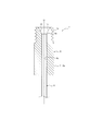
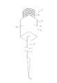
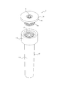
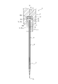
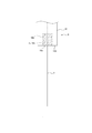
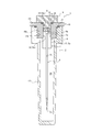
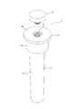
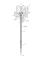
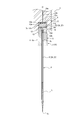
- FIG. 1 It is a side view which shows the chip device which concerns on one Embodiment. It is sectional drawing of the chip device shown in FIG. It is a perspective view of the chip device shown in FIG. It is a side view which shows the state when the chip device shown in FIG. 1 is placed. It is sectional drawing which shows the chip container set which concerns on one Embodiment. It is a perspective view which shows the state when the cap is closed in the container shown in FIG. It is a perspective view which shows the state when the cap is opened in the container shown in FIG. It is sectional drawing which shows the chip electrode apparatus which concerns on one Embodiment. It is a side view of the electrode device shown in FIG. It is sectional drawing which shows the chip container set which concerns on other embodiment.
- FIG. 5 is a perspective view showing a state when the closing cap is opened with the cap closed in the container shown in FIG. It is sectional drawing which shows the chip electrode apparatus which concerns on another Embodiment in the state which the electrode terminal and the holder terminal are in contact with each other. It is sectional drawing which shows the chip electrode device shown in FIG. 12 in a state where an electrode terminal and a holder terminal are separated from each other.
- the chip device 1 shown in FIGS. 1 to 4 constitutes a chip container set 3 by combining with the container 2 shown in FIGS. 5 to 7 containing the chip device 1, and the chip container set 3 is formed in FIGS. 8 to 9.
- the chip electrode device 5 is configured by combining with the electrode device 4 shown in the above.
- the application of the chip device 1 is not limited to that used in combination with the container 2 and the electrode device 4.
- the chip device 1 has a tubular chip 6 and a base 8 connected to the rear end portion 6a of the chip 6 and having a base connecting portion 7a as a first connecting portion. ing.
- the base connecting portion 7a is detachably connected to the container connecting portion 7b as a second connecting portion provided in the container 2 accommodating the chip 6. Further, the base connecting portion 7a is detachably connected to the holder connecting portion 7c as the second connecting portion provided on the electrode holder 10.
- the electrode holder 10 projects the linear electrode 9 introduced into the rear end portion 6a of the chip 6.
- the chip 6 is formed as a nanochip in which the tip portion 6b has an inner diameter on the nano-order, but the chip 6 is not limited to this.
- the tip portion 6b of the chip 6 has an inner diameter of, for example, 100 nm.
- the tip 6 has a cylindrical shape centered on an axis O in which the tip portion 6b gradually reduces in diameter toward the tip, but the tip 6 is not limited to this.
- the chip 6 is made of glass, for example.
- the base 8 is formed of, for example, a synthetic resin, and is fixed to the rear end portion 6a of the chip 6 by, for example, an appropriate means.
- Means for fixing are, for example, adhesion, frictional engagement, unevenness engagement, welding, insert molding and the like.
- the base 8 has a square tubular shape centered on the axis O, but is not limited to this.
- the base 8 is provided so as to project toward the rear end side of the rear end portion 6a of the chip 6, but is not limited to this.
- the base 8 has a grip portion 11 that is located between the base connecting portion 7a and the tip portion 6b of the chip 6 and widens in the radial direction of the chip 6, but is not limited to this.
- the base 8 has an access hole 12 communicating with the rear end portion 6a of the chip 6, but is not limited to this.
- the access hole 12 has a guide surface 13 whose diameter gradually decreases toward the rear end portion 6a of the chip 6, but is not limited to this.
- the guide surface 13 has a conical surface shape, but is not limited to this.
- the tip of the guide surface 13 coincides with the rear end of the inner peripheral surface 6c of the chip 6, but is not limited to this.
- the base 8 has a grounding portion 14 that keeps the tip portion 6b of the chip 6 away from the flat surface S on which the chip 6 is placed, but is not limited to this.
- the ground contact portion 14 is located on the outer peripheral surface 8a of the base 8, but is not limited to this.
- the base 8 is a square columnar having an outer peripheral surface 8a having four planes, and each of these planes can function as a grounding portion 14, but is not limited to this. Further, the ground contact portion 14 is not limited to a flat surface, and may be, for example, a curved surface.
- the position of the center of gravity of the base 8 is appropriately set so that the tip portion 6b of the chip 6 is maintained in a state of being separated from the surface S by grounding the ground contact portion 14 to the surface S.
- the base connecting portion 7a and the container connecting portion 7b or the holder connecting portion 7c are configured to be connected by engaging with each other, but are not limited to this, and are configured to be connected by, for example, engaging by friction. You may.
- the base connection portion 7a and the container connection portion 7b or the holder connection portion 7c are configured to be connected by screwing, but are not limited to this, and are configured to be connected by engagement between irregularities other than screwing. May be done.
- the container 2 has a communication hole 15 for communicating the outside of the container 2 with the rear end portion 6a of the chip 6, but the present invention is not limited to this.
- the communication hole 15 is provided concentrically with the axial center O of the chip 6, but is not limited to this.
- the container 2 has a cap 16 having a container connecting portion 7b and a container main body 17 having a mouth portion 17a removably connected to the cap 16, but is not limited to this.
- the container 2 is made of, for example, a synthetic resin.
- the cap 16 has a tubular tubular wall 16a centered on the axis O and an annular flange 16b extending radially outward from the upper end of the tubular wall 16a, but is not limited thereto.
- the lower end of the inner peripheral surface 16c of the cylinder wall 16a constitutes the container connecting portion 7b.
- the remaining portion of the inner peripheral surface 16c of the cylinder wall 16a constitutes a communication hole 15.
- the tubular wall 16a has a cylindrical shape, but the present invention is not limited to this, and a tubular shape other than the cylindrical shape may be used.
- the flange 16b is annular, but is not limited to this, and may be an annular shape other than the annular shape.
- the vertical direction means the direction along the axis O
- the upward direction means the direction from the tip portion 6b of the chip 6 toward the rear end portion 6a of the chip 6 (that is, the upper direction in FIGS. 5 and 10).
- Means, and downward means the opposite direction.
- the outer peripheral surface of the tubular wall 16a is detachably connected to the inner peripheral surface 17b of the mouth portion 17a, but is not limited to this.
- the outer peripheral surface of the tubular wall 16a is configured to be connected to the inner peripheral surface 17b of the mouth portion 17a by engaging the irregularities with each other, but is not limited to this, and is configured to be connected by, for example, engaging by friction. You may.
- the outer peripheral surface of the cylinder wall 16a is configured to be connected to the inner peripheral surface 17b of the mouth portion 17a by screwing, but the present invention is not limited to this, and is configured to be connected by engagement of irregularities other than screwing. May be done.
- the mouth portion 17a of the container body 17 is cylindrical, but the present invention is not limited to this, and a tubular shape other than the cylindrical shape may be used.
- a body portion 17c surrounding the chip device 1 is connected to the mouth portion 17a.
- the body portion 17c has a bottomed tubular shape extending downward from the lower end of the mouth portion 17a, but is not limited to this.
- the shape of the body portion 17c is not limited to the bottomed tubular shape.
- the body portion 17c has a bottomed cylindrical shape, but is not limited to this, and may have a bottomed tubular shape other than the bottomed cylindrical shape.
- the chip electrode device 5 includes a chip device 1 and an electrode device 4.
- the electrode device 4 has an electrode holder 10 having a holder connecting portion 7c, and a linear electrode 9 protruding from the electrode holder 10 and introduced into the rear end portion 6a of the chip 6.
- the electrode 9 is made of a metal such as silver.
- the electrode holder 10 is made of, for example, a synthetic resin.
- the electrode holder 10 has a recess 10a that opens downward concentrically with the axial center O of the chip 6, but is not limited to this.
- the electrode 9 projects downward from the upper end surface 10b of the recess 10a concentrically with the axis O, but is not limited to this.
- the holder connecting portion 7c is composed of the inner peripheral surface 10c of the recess 10a, but is not limited to this.
- the electrode 9 extends to the tip end side portion of the chip 6 in a state where the base connecting portion 7a and the holder connecting portion 7c are connected, but the electrode 9 is not limited to this.
- the tip 6 is filled with the liquid L, and the tip portion 9a of the electrode 9 is immersed in the liquid L.
- the liquid L is filled in the tip portion 6b of the chip 6 without gaps, that is, so as not to contain air bubbles.
- the amount of liquid L and the length of the electrode 9 can be changed as appropriate.
- the recess 10a is formed in the tip portion 10d of the electrode holder 10, but is not limited to this.
- the tip portion 10d of the electrode holder 10 has a cylindrical shape, but the present invention is not limited to this, and for example, a tubular shape other than the cylindrical shape may be used.
- the chip device 1 is used for the purpose of measurement, injection, collection, etc. for a sample such as cells, but is not limited to this.
- the chip device 1 is distributed, sold, and stored in a state of being housed in the container 2 as shown in FIG. Then, at the time of use, the liquid L is introduced from the rear end portion 6a of the tip 6 in this state by using, for example, a pipette. That is, the liquid L is introduced into the tip 6 by inserting the pipette into the rear end portion 6a of the tip 6 through the communication hole 15 and the access hole 12. At this time, the pipette can be guided into the rear end portion 6a of the tip 6 by the guide surface 13 of the access hole 12.
- the chip container set 3 is centrifuged.
- the cap 16 of the container 2 is opened, and the chip device 1 is removed from the cap 16.
- the removed chip device 1 is placed on the surface S via the grounding portion 14, and the tip portion 6b of the chip 6 is observed with a microscope.
- the tip portion 6b of the chip 6 is maintained in a state of being separated from the surface S, contamination of the tip portion 6b of the chip 6 can be easily suppressed. If the tip 6b is not tightly filled with the liquid L, the chip device 1 is reattached to the cap 16, the cap 16 is closed, and the chip container set 3 is centrifuge again.
- the chip device 1 can be easily attached to and detached from the container 2 via the base connecting portion 7a and the container connecting portion 7b. Further, the chip device 1 can be easily attached to and detached from the container 2 by gripping the grip portion 11 with, for example, a finger.
- the chip device 1 is attached to the electrode device 4 as shown in FIG. That is, the electrode 9 is inserted into the rear end portion 6a of the chip 6 through the access hole 12, and the chip device 1 is attached to the electrode holder 10 via the base connecting portion 7a and the holder connecting portion 7c. At this time, the electrode 9 can be guided into the rear end portion 6a of the chip 6 by the guide surface 13 of the access hole 12. Then, by immersing the tip portion 6b of the chip 6 in the sample and applying an electric field between the sample and the electrode 9, the above-mentioned various purposes can be achieved.
- the chip device 1 can be easily attached to and detached from the electrode device 4 via the base connecting portion 7a and the holder connecting portion 7c. Further, the chip device 1 can be easily attached to and detached from the electrode device 4 by gripping the grip portion 11 with, for example, a finger.
- the chip device 1 not only the operation of attaching / detaching the chip 6 to / from the container 2 and the electrode holder 10 can be completed quickly, but also the chip is damaged due to an erroneous operation at the time of attachment / detachment and the necessary rework is required. Can be suppressed. Therefore, the efficiency of a series of operations for achieving the above-mentioned various purposes can be dramatically improved.
- the chip device 1 according to the above-described embodiment can be combined with the container 2 according to another embodiment shown in FIGS. 10 to 11 to form a chip container set 3 according to another embodiment.
- FIGS. 10 to 11 the elements corresponding to the elements in the above-described embodiment are designated by the same reference numerals.
- the container 2 is configured to form a sealed space 18 for accommodating the chip device 1.
- the container 2 further has a closing cap 19 that closes the communication hole 15 of the cap 16 so as to be openable.
- the blocking cap 19 is configured to be connected to the communication hole 15 by engaging the irregularities with each other, but the present invention is not limited to this, and the blocking cap 19 may be configured to be connected by engaging with friction.
- the blocking cap 19 is configured to be connected to the communication hole 15 by screwing, but the present invention is not limited to this, and the blocking cap 19 may be configured to be connected by engaging the irregularities other than the screwing.
- annular first seal member 20 is further provided between the communication hole 15 and the closing cap 19, but the present invention is not limited to this.
- the first seal member 20 is held by the closing cap 19, but the present invention is not limited to this, and the first seal member 20 may be held by the cap 16.
- annular second seal member 21 is further provided between the cap 16 and the mouth portion 17a, but the present invention is not limited to this. The second seal member 21 may be held by either the cap 16 or the mouth portion 17a.
- the chip container set 3 is, for example, distributed, sold, and stored in a state where the inside of the container 2 is filled with a desired fluid such as a liquid L and the chip device 1 is housed. Further, the chip container set 3 can be used, for example, for the same purpose and method as in the case of the above-described embodiment by removing the blocking cap 19 from the cap 16.
- the chip device 1 according to the above-described embodiment can be combined with the electrode device 4 according to another embodiment shown in FIGS. 12 to 13 to form a chip electrode device 5 according to another embodiment.
- the same reference numerals are given to the elements corresponding to the elements in the above-described embodiment.
- the electrode holder 10 has an electrode terminal 22 as a first terminal connected to the rear end portion of the electrode 9, and a holder terminal 23 as a second terminal that is detachably contacted with the first terminal.
- the electrode 9 constitutes the electrode device 24 by combining with the electrode terminal 22.
- the chip device 1 constitutes the chip electrode set 25 by combining with the electrode device 24.
- FIG. 12 shows a state in which the connection between the base connection portion 7a and the holder connection portion 7c is completed, and the electrode terminal 22 and the holder terminal 23 are in contact with each other.
- FIG. 12 shows a state in which the connection between the base connection portion 7a and the holder connection portion 7c is completed, and the electrode terminal 22 and the holder terminal 23 are in contact with each other.
- the electrode terminal 22 and the holder terminal 23 are each made of a metal such as silver.
- the electrode device 24 may be distributed, sold, and stored together with the chip device 1 or the chip container set 3 (for example, shown in FIG. 5 or FIG. 10), or may be distributed, sold, and stored separately from these.
- the electrode terminal 22 has a contact portion 22a arranged on the rear end surface of the base 8 and a shaft portion 22b connecting the contact portion 22a to the electrode 9, but is not limited to this.
- the contact portion 22a of the electrode terminal 22 has a disk shape centered on the axis O, but is not limited to this.
- the shaft portion 22b of the electrode terminal 22 has a columnar shape centered on the axis O, but is not limited to this.
- the rear end of the electrode 9 is connected to the tip of the shaft portion 22b, but the present invention is not limited to this.
- the holder terminal 23 has a contact portion 23a arranged on the upper end surface 10b of the recess 10a of the electrode holder 10 and a shaft portion 23b arranged in the recess communication hole 10e communicating with the recess 10a and communicating with the contact portion 23a.
- the contact portion 23a of the holder terminal 23 has a disk shape centered on the axis O, but is not limited to this.
- the shaft portion 23b of the holder terminal 23 has a columnar shape centered on the axis O, but is not limited to this.
- the recessed communication hole 10e is formed by a cylindrical inner peripheral surface centered on the axis O, but is not limited to this.
- the electrode device 24 is arranged in the chip device 1 after the liquid L is introduced into the chip 6 of the chip device 1, for example.
- the contact portion 22a of the electrode terminal 22 and the contact portion 23a of the holder terminal 23 are connected to the base 8. It is sandwiched between the rear end surface (upper end surface) and the upper end surface 10b of the recess 10a and comes into contact with each other. By contacting the electrode terminal 22 and the holder terminal 23 in this way, it is possible to apply an electric field between the sample and the electrode 9.
- the contact portion 22a of the electrode terminal 22 and the contact portion 23a of the holder terminal 23 can be separated from each other. Therefore, when the chip device 1 held by the electrode holder 10 is replaced, the electrode device 24 can also be replaced. Therefore, it is possible to prevent the liquid L adhering to the electrode 9 before the replacement of the chip device 1 from being mixed with the liquid L in the chip device 1 after the replacement. This effect is particularly remarkable when the chip devices 1 before and after replacement hold liquids L of different types from each other.
- Electrode device 1 Chip device 2 Container 3 Chip container set 4 Electrode device 5 Chip electrode device 6 Chip 6a Rear end of chip 6b Tip tip 6c Inner peripheral surface of chip 7a Base connection (first connection) 7b Container connection (second connection) 7c holder connection (second connection) 8 Base 8a Outer surface of the base 9 Electrode 10 Electrode holder 10a Recess 10b Upper end surface of the recess 10c Inner peripheral surface of the recess 10d Tip of the electrode holder 10e Recessed communication hole 11 Gripping part 12 Access hole 13 Guide surface 14 Grounding part 15 Communication hole 16 Cap 16a Cylinder wall 16b Flange 16c Cylinder wall inner peripheral surface 17 Container body 17a Mouth 17b Mouth inner peripheral surface 17c Body 18 Sealed space 19 Closing cap 20 1st sealing member 21 2nd sealing member 22 Electrode terminal ( 1st terminal) 22a Contact part 22b Shaft part 23 Holder terminal (second terminal) 23a Contact part 23b Shaft part 24 Electrode device 25 Chip electrode set O Axis center S plane L Liquid
Landscapes
- Health & Medical Sciences (AREA)
- Chemical & Material Sciences (AREA)
- Chemical Kinetics & Catalysis (AREA)
- Clinical Laboratory Science (AREA)
- Life Sciences & Earth Sciences (AREA)
- Engineering & Computer Science (AREA)
- Bioinformatics & Cheminformatics (AREA)
- Organic Chemistry (AREA)
- General Health & Medical Sciences (AREA)
- Wood Science & Technology (AREA)
- Zoology (AREA)
- Biotechnology (AREA)
- Biochemistry (AREA)
- General Engineering & Computer Science (AREA)
- Sustainable Development (AREA)
- Genetics & Genomics (AREA)
- Microbiology (AREA)
- Biomedical Technology (AREA)
- Molecular Biology (AREA)
- Analytical Chemistry (AREA)
- Hematology (AREA)
- Apparatus Associated With Microorganisms And Enzymes (AREA)
- Sampling And Sample Adjustment (AREA)
- Packaging Of Annular Or Rod-Shaped Articles, Wearing Apparel, Cassettes, Or The Like (AREA)
Abstract
チップデバイス(1)は、管状のチップ(6)と、チップ(6)の後端部(6a)に連なるとともに第1の接続部を備えるベース(8)とを有し、第1の接続部は、チップ(6)を収容する容器(2)に設けられた第2の接続部に離脱可能に接続される。
Description
本出願は、日本国特許出願2019-213560号(2019年11月26日出願)と日本国特許出願2020-70048号(2020年4月8日出願)の優先権を主張するものであり、当該出願の開示全体を、ここに参照のために取り込む。
本開示は、チップデバイス、チップ容器セット、チップ電極装置及びチップ電極セットに関する。
例えば特許文献1~4に記載されるような管状のチップが知られている。
このようなチップは、細胞などの試料に対する測定、注入、採取などの目的で以下のように用いられる場合がある。まず、チップの後端部から液体を導入する。次いで、チップを収容する容器にチップを保持させる。そして、容器を遠心分離機にかけ、チップの先端部に液体を隙間なく、つまり気泡が含まれないように充填する。そして、容器からチップを取出し、チップの先端部に液体が隙間なく充填されたか否かを顕微鏡で確認する。液体が隙間なく充填されていない場合はチップを再び遠心分離機にかける。液体が隙間なく充填されたことが確認されたら、線状の電極をチップの後端部から導入し、チップの後端部を電極ホルダに保持させる。これにより、電極の先端部がチップの先端部内の液体に浸される。そして、チップの先端部を試料に浸し、試料と電極との間に電界を付与することで、上述した種々の目的を達成することができる。
しかし、従来のチップは、容器にも電極ホルダにも容易に着脱することができなかった。
そこで本開示の目的は、チップを容器に容易に着脱することができるチップデバイス、チップを電極ホルダに容易に着脱することができるチップデバイス、チップを容器に容易に着脱することができるチップ容器セット、チップを電極ホルダに容易に着脱することができるチップ電極装置、及びチップを電極ホルダに容易に着脱することができるチップ電極セットを提供することにある。
幾つかの実施形態に係るチップデバイスは、管状のチップと、チップの後端部に連なるとともに第1の接続部を備えるベースとを有し、第1の接続部は、チップを収容する容器に設けられた第2の接続部に離脱可能に接続される。このような構成によれば、ベースを介することにより、チップを容器に容易に着脱することができる。
幾つかの実施形態に係るチップデバイスは、管状のチップと、チップの後端部に連なるとともに第1の接続部を備えるベースとを有し、第1の接続部は、電極ホルダに設けられた第2の接続部に離脱可能に接続され、電極ホルダは、チップの後端部に導入される線状の電極を突出させる。このような構成によれば、ベースを介することにより、チップを電極ホルダに容易に着脱することができる。
一実施形態に係るチップデバイスは、ベースが、第1の接続部とチップの先端部との間に位置するとともにチップの径方向に拡幅する把持部を有してもよい。このような構成によれば、把持部を用いることにより、チップを容器又は電極ホルダにより容易に着脱することができる。
一実施形態に係るチップデバイスは、ベースが、チップの後端部に連通するアクセス穴を有してもよい。このような構成によれば、アクセス穴を介することにより、チップの後端部に液体又は電極を容易に導入することができる。
一実施形態に係るチップデバイスは、アクセス穴が、チップの後端部に向けて徐々に縮径する案内面を有してもよい。このような構成によれば、案内面により、チップの後端部に液体又は電極をより容易に導入することができる。
一実施形態に係るチップデバイスは、ベースが、チップの先端部がチップを載置した平面状の面から離れた状態を維持する接地部を有してもよい。このような構成によれば、チップを載置する際に、チップの先端部の汚染を容易に抑制することができる。
一実施形態に係るチップデバイスは、接地部がベースの外周面に位置してもよい。このような構成によれば、チップの先端部を顕微鏡で観察する際に、チップの先端部の汚染を容易に抑制することができる。
一実施形態に係るチップデバイスは、接続部同士が凹凸同士の係合によって接続してもよい。このような構成によれば、チップを容器又は電極ホルダにより確実に保持させることができる。
一実施形態に係るチップデバイスは、接続部同士が螺合によって接続してもよい。このような構成によれば、チップを容器又は電極ホルダにより一層確実に保持させることができる。
一実施形態に係るチップデバイスは、先端部がナノオーダーの内径を有するナノチップとして形成されてもよい。このような構成によれば、チップデバイスによって細胞内器官などの試料の微小部分に対する測定、注入、採取などを容易に行うことができる。
幾つかの実施形態に係るチップ容器セットは、管状のチップと、チップの後端部に連なるとともに第1の接続部を備えるベースと、第1の接続部に離脱可能に接続する第2の接続部を備えるとともにチップを収容する容器とを有する。このような構成によれば、ベースを介することにより、チップを容器に容易に着脱することができる。
一実施形態に係るチップ容器セットは、容器が、容器の外部をチップの後端部に連通させる連通穴を有してもよい。このような構成によれば、連通穴を介することにより、チップを容器に収容した状態のままでチップの後端部から液体を導入し、そのまま遠心分離機にかけることができるので、チップの先端部への液体の充填作業を効率化することができる。
一実施形態に係るチップ容器セットは、容器が、第2の接続部を有するキャップと、キャップに離脱可能に接続する口部を備える容器本体とを有してもよい。このような構成によれば、簡単な構造によって容器を構成することができる。
一実施形態に係るチップ容器セットは、ベースが、第1の接続部とチップの先端部との間に位置するとともにチップの径方向に拡幅する把持部を有してもよい。このような構成によれば、把持部を用いることにより、チップを容器により容易に着脱することができる。
一実施形態に係るチップ容器セットは、ベースが、チップの後端部に連通するアクセス穴を有してもよい。このような構成によれば、アクセス穴を介することにより、チップの後端部に液体又は電極を容易に導入することができる。
一実施形態に係るチップ容器セットは、アクセス穴が、チップの後端部に向けて徐々に縮径する案内面を有してもよい。このような構成によれば、案内面により、チップの後端部に液体又は電極をより容易に導入することができる。
一実施形態に係るチップ容器セットは、ベースが、チップの先端部がチップを載置した平面状の面から離れた状態を維持する接地部を有してもよい。このような構成によれば、チップを載置する際に、チップの先端部の汚染を容易に抑制することができる。
一実施形態に係るチップ容器セットは、接地部がベースの外周面に位置してもよい。このような構成によれば、チップの先端部を顕微鏡で観察する際に、チップの先端部の汚染を容易に抑制することができる。
一実施形態に係るチップ容器セットは、接続部同士が凹凸同士の係合によって接続してもよい。このような構成によれば、チップを容器により確実に保持させることができる。
一実施形態に係るチップ容器セットは、接続部同士が螺合によって接続してもよい。このような構成によれば、チップを容器により一層確実に保持させることができる。
一実施形態に係るチップ容器セットは、チップデバイスが、先端部がナノオーダーの内径を有するナノチップとして形成されてもよい。このような構成によれば、チップデバイスによって細胞内器官などの試料の微小部分に対する測定、注入、採取などを容易に行うことができる。
幾つかの実施形態に係るチップ電極装置は、管状のチップと、チップの後端部に連なるとともに第1の接続部を備えるベースと、第1の接続部に離脱可能に接続する第2の接続部を備える電極ホルダと、電極ホルダから突出するとともにチップの後端部に導入される線状の電極とを有する。このような構成によれば、ベースを介することにより、チップを電極ホルダに容易に着脱することができる。
一実施形態に係るチップ電極装置は、ベースが、第1の接続部とチップの先端部との間に位置するとともにチップの径方向に拡幅する把持部を有してもよい。このような構成によれば、把持部を用いることにより、チップを電極ホルダにより容易に着脱することができる。
一実施形態に係るチップ電極装置は、ベースが、チップの後端部に連通するアクセス穴を有してもよい。このような構成によれば、アクセス穴を介することにより、チップの後端部に液体又は電極を容易に導入することができる。
一実施形態に係るチップ電極装置は、アクセス穴が、チップの後端部に向けて徐々に縮径する案内面を有してもよい。このような構成によれば、案内面により、チップの後端部に液体又は電極をより容易に導入することができる。
一実施形態に係るチップ電極装置は、ベースが、チップの先端部がチップを載置した平面状の面から離れた状態を維持する接地部を有してもよい。このような構成によれば、チップを載置する際に、チップの先端部の汚染を容易に抑制することができる。
一実施形態に係るチップ電極装置は、接地部がベースの外周面に位置してもよい。このような構成によれば、チップの先端部を顕微鏡で観察する際に、チップの先端部の汚染を容易に抑制することができる。
一実施形態に係るチップ電極装置は、接続部同士が凹凸同士の係合によって接続してもよい。このような構成によれば、チップを電極ホルダにより確実に保持させることができる。
一実施形態に係るチップ電極装置は、接続部同士が螺合によって接続してもよい。このような構成によれば、チップを電極ホルダにより一層確実に保持させることができる。
一実施形態に係るチップ電極装置は、チップデバイスが、先端部がナノオーダーの内径を有するナノチップとして形成されてもよい。このような構成によれば、チップデバイスによって細胞内器官などの試料の微小部分に対する測定、注入、採取などを容易に行うことができる。
一実施形態に係るチップ電極装置は、電極ホルダが、電極の後端部に連なる第1の端子と、第1の端子に離脱可能に接触する第2の端子とを有してもよい。このような構成によれば、電極ホルダに保持させるチップデバイスを交換する際に、電極と第1の端子とを備える電極デバイスも併せて交換することができる。したがって、チップデバイスの交換前に電極に付着していた液体が交換後のチップデバイス内の液体に混入することを抑制することができる。
幾つかの実施形態に係るチップ電極セットは、管状のチップと、チップの後端部に連なるとともに第1の接続部を備えるベースと、チップの後端部に導入される線状の電極と電極の後端部に連なる第1の端子とを備える電極デバイスとを有し、第1の接続部は、電極ホルダに設けられた第2の接続部に離脱可能に接続され、第1の端子は、電極ホルダに設けられた第2の端子に離脱可能に接触する。このような構成によれば、ベースを介することにより、チップを電極ホルダに容易に着脱することができる。また、このような構成によれば、電極ホルダに保持させるチップデバイスを交換する際に、電極デバイスも併せて交換することができる。したがって、チップデバイスの交換前に電極に付着していた液体が交換後のチップデバイス内の液体に混入することを抑制することができる。
本開示によれば、チップを容器に容易に着脱することができるチップデバイス、チップを電極ホルダに容易に着脱することができるチップデバイス、チップを容器に容易に着脱することができるチップ容器セット、チップを電極ホルダに容易に着脱することができるチップ電極装置、及びチップを電極ホルダに容易に着脱することができるチップ電極セットを提供することができる。
以下、図面を参照して、本開示に係る実施形態について詳細に例示説明する。
一実施形態において、図1~図4に示すチップデバイス1は、チップデバイス1を収容する図5~図7に示す容器2と組合せることでチップ容器セット3を構成し、図8~図9に示す電極装置4と組合せることでチップ電極装置5を構成する。しかし、チップデバイス1の用途は、容器2や電極装置4と組合せて使用するものに限らない。
図1~図4に示すように、チップデバイス1は、管状のチップ6と、チップ6の後端部6aに連なるとともに第1の接続部としてのベース接続部7aを備えるベース8とを有している。ベース接続部7aは、チップ6を収容する容器2に設けられた第2の接続部としての容器接続部7bに離脱可能に接続される。またベース接続部7aは、電極ホルダ10に設けられた第2の接続部としてのホルダ接続部7cに離脱可能に接続される。電極ホルダ10は、チップ6の後端部6aに導入される線状の電極9を突出させる。
チップ6は、先端部6bがナノオーダーの内径を有するナノチップとして形成されているが、これに限らない。チップ6の先端部6bは、例えば100nmの内径を有する。チップ6は、先端部6bが先端に向けて徐々に縮径する軸心Oを中心とする円筒状であるが、これに限らない。チップ6は例えばガラスで形成される。
ベース8は例えば合成樹脂で形成され、チップ6の後端部6aに例えば適宜の手段によって固着される。固着のための手段は例えば接着、摩擦による係合、凹凸同士の係合、溶着、インサート成形などである。
ベース8は軸心Oを中心とする角筒状であるが、これに限らない。ベース8はチップ6の後端部6aよりも後端側に突出するように設けられているが、これに限らない。
ベース8は、ベース接続部7aとチップ6の先端部6bとの間に位置するとともにチップ6の径方向に拡幅する把持部11を有しているが、これに限らない。
ベース8は、チップ6の後端部6aに連通するアクセス穴12を有しているが、これに限らない。アクセス穴12は、チップ6の後端部6aに向けて徐々に縮径する案内面13を有しているが、これに限らない。案内面13は円錐面状であるが、これに限らない。案内面13の先端はチップ6の内周面6cの後端と一致しているが、これに限らない。
ベース8は、チップ6の先端部6bがチップ6を載置した平面状の面Sから離れた状態を維持する接地部14を有しているが、これに限らない。接地部14はベース8の外周面8aに位置するが、これに限らない。ベース8は4つの平面を備える外周面8aを有する四角柱状であり、これら平面それぞれが接地部14として機能することができるが、これに限らない。また、接地部14は平面状に限らず、例えば曲面状であってもよい。ベース8の重心位置は、接地部14を面Sに接地させることで、チップ6の先端部6bが面Sから離れた状態を維持するように適切に設定されている。
ベース接続部7aと容器接続部7b又はホルダ接続部7cとは、凹凸同士の係合によって接続するように構成されているが、これに限らず例えば、摩擦による係合によって接続するように構成されてもよい。ベース接続部7aと容器接続部7b又はホルダ接続部7cとは、螺合によって接続するように構成されているが、これに限らず、螺合以外の凹凸同士の係合によって接続するように構成されてもよい。
図5~図7に示すように、容器2は、容器2の外部をチップ6の後端部6aに連通させる連通穴15を有しているが、これに限らない。連通穴15はチップ6の軸心Oと同心状に設けられているが、これに限らない。
容器2は、容器接続部7bを有するキャップ16と、キャップ16に離脱可能に接続する口部17aを備える容器本体17とを有しているが、これに限らない。容器2は例えば合成樹脂で形成される。
キャップ16は、軸心Oを中心とする筒状の筒壁16aと、筒壁16a上端部から径方向外側に延在する環状のフランジ16bとを有しているが、これに限らない。筒壁16aの内周面16cの下端部は、容器接続部7bを構成している。筒壁16aの内周面16cの残りの部分は、連通穴15を構成している。筒壁16aは円筒状であるがこれに限らず、円筒状以外の筒状であってもよい。フランジ16bは円環状であるがこれに限らず、円環状以外の環状であってもよい。
本明細書において、上下方向とは軸心Oに沿う方向を意味し、上方とはチップ6の先端部6bからチップ6の後端部6aに向かう方向(つまり、図5及び図10における上方)を意味し、下方とはその反対方向を意味している。
筒壁16aの外周面は、口部17aの内周面17bに離脱可能に接続するが、これに限らない。筒壁16aの外周面は、口部17aの内周面17bに凹凸同士の係合によって接続するように構成されているが、これに限らず例えば、摩擦による係合によって接続するように構成されてもよい。筒壁16aの外周面は、口部17aの内周面17bに螺合によって接続するように構成されているが、これに限らず、螺合以外の凹凸同士の係合によって接続するように構成されてもよい。
容器本体17の口部17aは円筒状であるがこれに限らず、円筒状以外の筒状であってもよい。口部17aにはチップデバイス1を囲繞する胴部17cが連なっている。胴部17cは、口部17aの下端から下方に延びる有底筒状であるが、これに限らない。例えば、胴部17cの形状は有底筒状に限らない。胴部17cは有底円筒状であるがこれに限らず、有底円筒状以外の有底筒状であってもよい。
図8~図9に示すように、チップ電極装置5はチップデバイス1と電極装置4とを有している。電極装置4は、ホルダ接続部7cを備える電極ホルダ10と、電極ホルダ10から突出するとともにチップ6の後端部6aに導入される線状の電極9とを有している。電極9は例えば銀などの金属で形成される。電極ホルダ10は例えば合成樹脂で形成される。
電極ホルダ10はチップ6の軸心Oと同心状の下方に向けて開放する凹部10aを有しているが、これに限らない。電極9は凹部10aの上端面10bから下方に軸心Oと同心状に突出しているが、これに限らない。ホルダ接続部7cは凹部10aの内周面10cによって構成されているが、これに限らない。電極9は、ベース接続部7aとホルダ接続部7cとを接続した状態でチップ6の先端側部分まで延びているが、これに限らない。チップ6内には液体Lが充填されており、電極9の先端部9aは液体Lに浸されている。液体Lはチップ6の先端部6b内に隙間なく、つまり気泡が含まれないように充填されている。液体Lの量と電極9の長さは適宜変更可能である。
凹部10aは電極ホルダ10の先端部10dに形成されているが、これに限らない。電極ホルダ10の先端部10dは円筒状であるが、これに限らず例えば、円筒状以外の筒状であってもよい。
本実施形態では、チップデバイス1は、細胞などの試料に対する測定、注入、採取などの目的で以下のように用いられるが、これに限らない。
まず、チップデバイス1は、図5に示すように容器2に収容された状態で流通、販売、保管される。そして、使用に際しては、この状態のままで例えばピペットを用いてチップ6の後端部6aから液体Lが導入される。すなわち、ピペットを連通穴15とアクセス穴12を通じてチップ6の後端部6aに挿入することで、チップ6内に液体Lが導入される。このとき、ピペットをアクセス穴12の案内面13によってチップ6の後端部6a内に案内することができる。液体Lが導入されると、チップ容器セット3が遠心分離機にかけられる。
遠心分離機での処理が終わると、容器2のキャップ16が開かれ、キャップ16からチップデバイス1が取外される。取外されたチップデバイス1は、図4に示すように、接地部14を介して面Sに載置され、チップ6の先端部6bが顕微鏡で観察される。このとき、チップ6の先端部6bが面Sから離れた状態を維持されるので、チップ6の先端部6bの汚染を容易に抑制することができる。液体Lが先端部6bに隙間なく充填されていない場合は、チップデバイス1は再びキャップ16に取付けられ、キャップ16が閉じられ、チップ容器セット3が遠心分離機に再びかけられる。
このように、チップデバイス1は、ベース接続部7aと容器接続部7bを介することにより、容器2に容易に着脱することができる。また、チップデバイス1は、把持部11を例えば指で把持することにより、容器2への着脱操作を容易に行うことができる。
この観察により液体Lがチップ6の先端部6bに隙間なく充填されたことが確認されたら、チップデバイス1は、図8に示すように、電極装置4に取付けられる。すなわち、電極9がアクセス穴12を通じてチップ6の後端部6aに挿入され、ベース接続部7aとホルダ接続部7cを介してチップデバイス1が電極ホルダ10に取付けられる。このとき、電極9をアクセス穴12の案内面13によってチップ6の後端部6a内に案内することができる。そして、チップ6の先端部6bを試料に浸し、試料と電極9との間に電界を付与することで、上述した種々の目的を達成することができる。
このように、チップデバイス1は、ベース接続部7aとホルダ接続部7cを介することにより、電極装置4に容易に着脱することができる。また、チップデバイス1は、把持部11を例えば指で把持することにより、電極装置4への着脱操作を容易に行うことができる。
本実施形態に係るチップデバイス1によれば、容器2及び電極ホルダ10に対するチップ6の着脱操作を速やかに済ませることができるだけでなく、着脱時の誤操作によるチップの破損とそれによって必要となる再作業の発生を抑制することができる。したがって、上述した種々の目的を達成するための一連の作業の効率を飛躍的に高めることができる。
前述した一実施形態に係るチップデバイス1は、図10~図11に示す他の実施形態に係る容器2と組合せることで他の実施形態に係るチップ容器セット3を構成することもできる。なお、図10~図11においては、前述した一実施形態における要素に対応する要素に同一の符号を付している。
本実施形態では、容器2は、チップデバイス1を収容する密封空間18を形成するように構成されている。このために容器2は、キャップ16の連通穴15を開放可能に閉塞する閉塞キャップ19を更に有している。閉塞キャップ19は、連通穴15に凹凸同士の係合によって接続するように構成されているが、これに限らず例えば、摩擦による係合によって接続するように構成されてもよい。閉塞キャップ19は、連通穴15に螺合によって接続するように構成されているが、これに限らず、螺合以外の凹凸同士の係合によって接続するように構成されてもよい。
また、連通穴15と閉塞キャップ19との間には環状の第1シール部材20が更に設けられているが、これに限らない。第1シール部材20は閉塞キャップ19に保持されているが、これに限らず、キャップ16に保持されてもよい。また、キャップ16と口部17aとの間には環状の第2シール部材21が更に設けられているが、これに限らない。第2シール部材21はキャップ16と口部17aとの何れに保持されてもよい。
チップ容器セット3は、例えば容器2内を例えば液体Lなどの所望の流体で満たし、且つチップデバイス1を収容した状態で例えば流通、販売、保管される。また、チップ容器セット3は、閉塞キャップ19をキャップ16から取外すことにより例えば、前述した一実施形態の場合と同様の目的及び方法で使用することができる。
前述した一実施形態に係るチップデバイス1は、図12~図13に示す他の実施形態に係る電極装置4と組合せることで他の実施形態に係るチップ電極装置5を構成することもできる。なお、図12~図13においては、前述した一実施形態における要素に対応する要素に同一の符号を付している。
本実施形態では、電極ホルダ10が、電極9の後端部に連なる第1の端子として電極端子22と、第1の端子に離脱可能に接触する第2の端子としてのホルダ端子23とを有している。本実施形態では、電極9は、電極端子22と組合せることで電極デバイス24を構成する。また、本実施形態では、チップデバイス1は、電極デバイス24と組合せることでチップ電極セット25を構成する。なお、図12は、ベース接続部7aとホルダ接続部7cの接続が完了し、電極端子22とホルダ端子23が互いに接触した状態を示している。図13は、ベース接続部7aとホルダ接続部7cが接続状態から離脱状態に至る途中であり、電極端子22とホルダ端子23が互いに離脱した状態を示している。電極端子22及びホルダ端子23はそれぞれ例えば、銀などの金属で形成される。
電極デバイス24は、チップデバイス1又は(例えば図5又は図10に示す)チップ容器セット3と共に流通、販売、保管されてもよいし、これらと別々に流通、販売、保管されてもよい。
電極端子22は、ベース8の後端面上に配置される接触部22aと、接触部22aを電極9に連ねる軸部22bとを有しているが、これに限らない。電極端子22の接触部22aは軸心Oを中心とする円板状であるが、これに限らない。電極端子22の軸部22bは軸心Oを中心とする円柱状であるが、これに限らない。軸部22bの先端に電極9の後端が連なっているが、これに限らない。
ホルダ端子23は、電極ホルダ10の凹部10aの上端面10b上に配置される接触部23aと、凹部10aに連通する凹部連通穴10e内に配置されるとともに接触部23aに連なる軸部23bとを有しているが、これに限らない。ホルダ端子23の接触部23aは軸心Oを中心とする円板状であるが、これに限らない。ホルダ端子23の軸部23bは軸心Oを中心とする円柱状であるが、これに限らない。凹部連通穴10eは軸心Oを中心とする円柱面状の内周面によって形成されているが、これに限らない。
電極デバイス24は例えば、チップデバイス1のチップ6内に液体Lが導入された後に、チップデバイス1に配置される。
電極デバイス24がチップデバイス1に配置された状態で、ベース接続部7aをホルダ接続部7cに接続することで、電極端子22の接触部22aとホルダ端子23の接触部23aとが、ベース8の後端面(上端面)と凹部10aの上端面10bとに挟まれ、互いに接触する。このように電極端子22とホルダ端子23とが接触することで、試料と電極9との間に電界を付与することが可能となる。
また、ベース接続部7aをホルダ接続部7cから離脱させることで、電極端子22の接触部22aとホルダ端子23の接触部23aとを互いに離脱させることができる。したがって、電極ホルダ10に保持させるチップデバイス1を交換する際に、電極デバイス24も併せて交換することができる。よって、チップデバイス1の交換前に電極9に付着していた液体Lが交換後のチップデバイス1内の液体Lに混入することを抑制することができる。この効果は、交換前後のチップデバイス1が互いに異なる種類の液体Lを保持している場合に特に顕著である。
なお、本実施形態のチップ電極装置5を用いて細胞などの試料に対する測定、注入、採取などを行う場合におけるその他の要領は、前述した一実施形態の場合と同様である。
前述した実施形態は本開示の一例であり、種々変更可能であることはいうまでもない。
1 チップデバイス
2 容器
3 チップ容器セット
4 電極装置
5 チップ電極装置
6 チップ
6a チップの後端部
6b チップの先端部
6c チップの内周面
7a ベース接続部(第1の接続部)
7b 容器接続部(第2の接続部)
7c ホルダ接続部(第2の接続部)
8 ベース
8a ベースの外周面
9 電極
10 電極ホルダ
10a 凹部
10b 凹部の上端面
10c 凹部の内周面
10d 電極ホルダの先端部
10e 凹部連通穴
11 把持部
12 アクセス穴
13 案内面
14 接地部
15 連通穴
16 キャップ
16a 筒壁
16b フランジ
16c 筒壁の内周面
17 容器本体
17a 口部
17b 口部の内周面
17c 胴部
18 密封空間
19 閉塞キャップ
20 第1シール部材
21 第2シール部材
22 電極端子(第1の端子)
22a 接触部
22b 軸部
23 ホルダ端子(第2の端子)
23a 接触部
23b 軸部
24 電極デバイス
25 チップ電極セット
O 軸心
S 面
L 液体
2 容器
3 チップ容器セット
4 電極装置
5 チップ電極装置
6 チップ
6a チップの後端部
6b チップの先端部
6c チップの内周面
7a ベース接続部(第1の接続部)
7b 容器接続部(第2の接続部)
7c ホルダ接続部(第2の接続部)
8 ベース
8a ベースの外周面
9 電極
10 電極ホルダ
10a 凹部
10b 凹部の上端面
10c 凹部の内周面
10d 電極ホルダの先端部
10e 凹部連通穴
11 把持部
12 アクセス穴
13 案内面
14 接地部
15 連通穴
16 キャップ
16a 筒壁
16b フランジ
16c 筒壁の内周面
17 容器本体
17a 口部
17b 口部の内周面
17c 胴部
18 密封空間
19 閉塞キャップ
20 第1シール部材
21 第2シール部材
22 電極端子(第1の端子)
22a 接触部
22b 軸部
23 ホルダ端子(第2の端子)
23a 接触部
23b 軸部
24 電極デバイス
25 チップ電極セット
O 軸心
S 面
L 液体
Claims (21)
- 管状のチップと、
前記チップの後端部に連なるとともに第1の接続部を備えるベースとを有し、
前記第1の接続部は、前記チップを収容する容器に設けられた第2の接続部に離脱可能に接続される
チップデバイス。 - 管状のチップと、
前記チップの後端部に連なるとともに第1の接続部を備えるベースとを有し、
前記第1の接続部は、電極ホルダに設けられた第2の接続部に離脱可能に接続され、
前記電極ホルダは、前記チップの前記後端部に導入される線状の電極を突出させる
チップデバイス。 - 前記ベースが、前記第1の接続部と前記チップの先端部との間に位置するとともに前記チップの径方向に拡幅する把持部を有する、請求項1又は2に記載のチップデバイス。
- 前記ベースが、前記チップの前記後端部に連通するアクセス穴を有する、請求項1~3の何れか1項に記載のチップデバイス。
- 前記アクセス穴が、前記チップの前記後端部に向けて徐々に縮径する案内面を有する、請求項4に記載のチップデバイス。
- 前記ベースが、前記チップの先端部が前記チップを載置した平面状の面から離れた状態を維持する接地部を有する、請求項1~5の何れか1項に記載のチップデバイス。
- 前記接地部が前記ベースの外周面に位置する、請求項6に記載のチップデバイス。
- 前記接続部同士が凹凸同士の係合によって接続する、請求項1~7の何れか1項に記載のチップデバイス。
- 前記接続部同士が螺合によって接続する、請求項1~8の何れか1項に記載のチップデバイス。
- 管状のチップと、
前記チップの後端部に連なるとともに第1の接続部を備えるベースと、
前記第1の接続部に離脱可能に接続する第2の接続部を備えるとともに前記チップを収容する容器とを有する
チップ容器セット。 - 前記容器が、前記容器の外部を前記チップの前記後端部に連通させる連通穴を有する、請求項10に記載のチップ容器セット。
- 前記容器が、前記第2の接続部を有するキャップと、前記キャップに離脱可能に接続する口部を備える容器本体とを有する、請求項10又は11に記載のチップ容器セット。
- 前記ベースが、前記第1の接続部と前記チップの先端部との間に位置するとともに前記チップの径方向に拡幅する把持部を有する、請求項10~12の何れか1項に記載のチップ容器セット。
- 前記ベースが、前記チップの前記後端部に連通するアクセス穴を有する、請求項10~13の何れか1項に記載のチップ容器セット。
- 前記アクセス穴が、前記チップの前記後端部に向けて徐々に縮径する案内面を有する、請求項14に記載のチップ容器セット。
- 管状のチップと、
前記チップの後端部に連なるとともに第1の接続部を備えるベースと、
前記第1の接続部に離脱可能に接続する第2の接続部を備える電極ホルダと、
前記電極ホルダから突出するとともに前記チップの前記後端部に導入される線状の電極とを有する
チップ電極装置。 - 前記ベースが、前記第1の接続部と前記チップの先端部との間に位置するとともに前記チップの径方向に拡幅する把持部を有する、請求項16に記載のチップ電極装置。
- 前記ベースが、前記チップの前記後端部に連通するアクセス穴を有する、請求項16又は17に記載のチップ電極装置。
- 前記アクセス穴が、前記チップの前記後端部に向けて徐々に縮径する案内面を有する、請求項18に記載のチップ電極装置。
- 前記電極ホルダが、前記電極の後端部に連なる第1の端子と、前記第1の端子に離脱可能に接触する第2の端子とを有する、請求項16~19の何れか1項に記載のチップ電極装置。
- 管状のチップと、
前記チップの後端部に連なるとともに第1の接続部を備えるベースと、
前記チップの前記後端部に導入される線状の電極と前記電極の後端部に連なる第1の端子とを備える電極デバイスとを有し、
前記第1の接続部は、電極ホルダに設けられた第2の接続部に離脱可能に接続され、
前記第1の端子は、前記電極ホルダに設けられた第2の端子に離脱可能に接触する
チップ電極セット。
Priority Applications (4)
| Application Number | Priority Date | Filing Date | Title |
|---|---|---|---|
| EP20893903.3A EP4067471A4 (en) | 2019-11-26 | 2020-10-16 | Tip device, tip container set, tip electrode device, and tip electrode set |
| CN202080082328.6A CN114746537A (zh) | 2019-11-26 | 2020-10-16 | 针头器件、针头容器组件、针头电极装置及针头电极组件 |
| US17/755,759 US12059675B2 (en) | 2019-11-26 | 2020-10-16 | Tip device, tip container set, tip electrode apparatus, and tip electrode set |
| EP24197295.9A EP4450607A3 (en) | 2019-11-26 | 2020-10-16 | Tip device, tip container set, tip electrode apparatus, and tip electrode set |
Applications Claiming Priority (4)
| Application Number | Priority Date | Filing Date | Title |
|---|---|---|---|
| JP2019-213560 | 2019-11-26 | ||
| JP2019213560 | 2019-11-26 | ||
| JP2020070048A JP7367596B2 (ja) | 2019-11-26 | 2020-04-08 | チップデバイス、チップ容器セット、チップ電極装置及びチップ電極セット |
| JP2020-070048 | 2020-04-08 |
Publications (1)
| Publication Number | Publication Date |
|---|---|
| WO2021106422A1 true WO2021106422A1 (ja) | 2021-06-03 |
Family
ID=76129529
Family Applications (1)
| Application Number | Title | Priority Date | Filing Date |
|---|---|---|---|
| PCT/JP2020/039180 Ceased WO2021106422A1 (ja) | 2019-11-26 | 2020-10-16 | チップデバイス、チップ容器セット、チップ電極装置及びチップ電極セット |
Country Status (4)
| Country | Link |
|---|---|
| US (1) | US12059675B2 (ja) |
| EP (2) | EP4067471A4 (ja) |
| CN (1) | CN114746537A (ja) |
| WO (1) | WO2021106422A1 (ja) |
Citations (7)
| Publication number | Priority date | Publication date | Assignee | Title |
|---|---|---|---|---|
| JPS62179084U (ja) * | 1986-05-07 | 1987-11-13 | ||
| JP2002542017A (ja) * | 1999-04-16 | 2002-12-10 | ハミルトン・ボナドゥーツ・アーゲー | ピペットチップ、及びピペット装置、及びピペットチップとピペット装置の連結体 |
| WO2003057819A1 (en) * | 2002-01-07 | 2003-07-17 | Uab Research Foundation | Electroporation cuvette-pipette tips, multi-well cuvette arrays, and electrode template apparatus adapted for automation and uses thereof |
| JP2008509709A (ja) * | 2003-12-02 | 2008-04-03 | セレクトリコン アーベー | 空間的に限定されたエレクトロポレーション方法およびその装置 |
| JP2018143999A (ja) * | 2017-03-08 | 2018-09-20 | 株式会社アイカムス・ラボ | ピペットチップ、ピペットチップの成型金型及びピペットチップの成型方法 |
| JP2019213560A (ja) | 2004-12-08 | 2019-12-19 | ジェン−プローブ・インコーポレーテッド | 複数型のヒトパピローマウイルスに由来する核酸の検出 |
| JP2020070048A (ja) | 2018-10-30 | 2020-05-07 | 花王株式会社 | ポンプディスペンサー |
Family Cites Families (18)
| Publication number | Priority date | Publication date | Assignee | Title |
|---|---|---|---|---|
| US5431280A (en) * | 1994-03-17 | 1995-07-11 | Humagen Fertility Diagnostics Inc. | Closure cap for holding pipets during shipping |
| US5977503A (en) * | 1997-11-03 | 1999-11-02 | Leach Thomas S. | Attachment device for electrical discharge machine |
| JPH11295282A (ja) | 1998-04-10 | 1999-10-29 | Rieko Naito | ピペット用チップ |
| JP3406860B2 (ja) * | 1999-04-21 | 2003-05-19 | 株式会社ソディック | 放電加工用パイプ電極ホルダ |
| JP2000342686A (ja) * | 1999-06-01 | 2000-12-12 | Terumo Corp | 医療用針および医療用具 |
| JP4767655B2 (ja) * | 2005-10-28 | 2011-09-07 | テルモ株式会社 | プロテクタ及び針セット |
| EP2863226A1 (en) | 2007-11-02 | 2015-04-22 | Humanix Co., Ltd. | Method of capturing fluid and analyzing components thereof and system for capturing and analyzing fluid |
| US8274008B2 (en) * | 2008-10-15 | 2012-09-25 | Lam Research Corporation | EDM spindle assembly with fluid seal |
| US20110300621A1 (en) | 2009-12-10 | 2011-12-08 | Roche Molecular Systems, Inc. | Process head positioning |
| WO2012042904A1 (ja) * | 2010-09-30 | 2012-04-05 | パナソニック株式会社 | バイオセンサ収納体と、当該バイオセンサを用いる測定装置 |
| JP2014530358A (ja) | 2011-09-25 | 2014-11-17 | セラノス, インコーポレイテッド | 多重分析のためのシステム及び方法 |
| JP2015175837A (ja) * | 2014-03-18 | 2015-10-05 | ソニー株式会社 | ピペットチップ用板状部材、ピペットチップ、液体撹拌用キット及び液体撹拌装置 |
| WO2015193957A1 (ja) * | 2014-06-17 | 2015-12-23 | ヤマハ発動機株式会社 | シリンダチップ装着用ヘッド、これを用いたヘッド装置及び移動装置 |
| JP6090387B2 (ja) | 2014-12-15 | 2017-03-08 | 横河電機株式会社 | 細胞吸引システム及びこれを用いた細胞内物質の吸引作業を行う方法 |
| WO2017210334A1 (en) * | 2016-05-31 | 2017-12-07 | Massachusetts Institute Of Technology | Hydrodynamically controlled electric fields for high throughput transformation & high throughput parallel transformation platform |
| JP6953888B2 (ja) | 2017-08-10 | 2021-10-27 | 横河電機株式会社 | 吸引システム、吸引方法及びプログラム |
| JP6444560B1 (ja) | 2018-08-30 | 2018-12-26 | 株式会社マイクロブラッドサイエンス | 血液採取器具 |
| CN221106122U (zh) * | 2023-07-19 | 2024-06-11 | 胡兴姬 | 一种生猪养殖用注射装置 |
-
2020
- 2020-10-16 EP EP20893903.3A patent/EP4067471A4/en not_active Withdrawn
- 2020-10-16 WO PCT/JP2020/039180 patent/WO2021106422A1/ja not_active Ceased
- 2020-10-16 US US17/755,759 patent/US12059675B2/en active Active
- 2020-10-16 CN CN202080082328.6A patent/CN114746537A/zh active Pending
- 2020-10-16 EP EP24197295.9A patent/EP4450607A3/en active Pending
Patent Citations (7)
| Publication number | Priority date | Publication date | Assignee | Title |
|---|---|---|---|---|
| JPS62179084U (ja) * | 1986-05-07 | 1987-11-13 | ||
| JP2002542017A (ja) * | 1999-04-16 | 2002-12-10 | ハミルトン・ボナドゥーツ・アーゲー | ピペットチップ、及びピペット装置、及びピペットチップとピペット装置の連結体 |
| WO2003057819A1 (en) * | 2002-01-07 | 2003-07-17 | Uab Research Foundation | Electroporation cuvette-pipette tips, multi-well cuvette arrays, and electrode template apparatus adapted for automation and uses thereof |
| JP2008509709A (ja) * | 2003-12-02 | 2008-04-03 | セレクトリコン アーベー | 空間的に限定されたエレクトロポレーション方法およびその装置 |
| JP2019213560A (ja) | 2004-12-08 | 2019-12-19 | ジェン−プローブ・インコーポレーテッド | 複数型のヒトパピローマウイルスに由来する核酸の検出 |
| JP2018143999A (ja) * | 2017-03-08 | 2018-09-20 | 株式会社アイカムス・ラボ | ピペットチップ、ピペットチップの成型金型及びピペットチップの成型方法 |
| JP2020070048A (ja) | 2018-10-30 | 2020-05-07 | 花王株式会社 | ポンプディスペンサー |
Non-Patent Citations (1)
| Title |
|---|
| See also references of EP4067471A4 |
Also Published As
| Publication number | Publication date |
|---|---|
| US12059675B2 (en) | 2024-08-13 |
| EP4067471A1 (en) | 2022-10-05 |
| EP4450607A3 (en) | 2025-03-05 |
| CN114746537A (zh) | 2022-07-12 |
| EP4450607A2 (en) | 2024-10-23 |
| EP4067471A4 (en) | 2024-06-26 |
| US20220387989A1 (en) | 2022-12-08 |
Similar Documents
| Publication | Publication Date | Title |
|---|---|---|
| KR100985426B1 (ko) | 시약 용기를 자동 개방하기 위한 시스템 | |
| US12085559B2 (en) | Replaceable ground electrode for electrophysiology, electrode rejuvenating apparatus, and related methods and systems | |
| US11125709B2 (en) | Cartridge, kit comprising cartridge, electric measuring apparatus, and electric measuring method | |
| CN103260759A (zh) | 过滤装置和方法 | |
| US20200171480A1 (en) | Adapter for receiving a capillary | |
| JP2000314719A (ja) | 電気泳動チップ | |
| EP3060925B1 (en) | Kit, method and assembly for preparing a sample | |
| JP2021087416A (ja) | チップデバイス、チップ容器セット、チップ電極装置及びチップ電極セット | |
| CN110461474B (zh) | 用于电化学容器的封闭机构、电化学容器和实验室设备 | |
| US9829416B2 (en) | Closure with septum strip | |
| JP6458478B2 (ja) | 採集容器用アダプタ | |
| JP2005238158A (ja) | 遠心管 | |
| US12059675B2 (en) | Tip device, tip container set, tip electrode apparatus, and tip electrode set | |
| US20200170626A1 (en) | Device for preparing a sample to be analyzed and method for preparing a sample to be analyzed | |
| KR101569175B1 (ko) | 주사기 어댑터 | |
| US12222488B2 (en) | Observation carrier for microscope | |
| US5891327A (en) | Centrifuge tube with rotational position index | |
| US20090202394A1 (en) | Vial with coaxial small sample tube insert | |
| JP4324584B2 (ja) | 試薬ボトル収容装置 | |
| US11224882B2 (en) | Rotor that improves operability of sample containers and centrifuge in which same is used | |
| JP2010023868A (ja) | 採血管用使い捨て開栓ブロックとそれを使用した開栓装置 | |
| EP4541463A1 (en) | Pipette tip with outside sealing collar | |
| JP2011242409A (ja) | キャピラリ電気泳動装置 | |
| WO2018174040A1 (ja) | 体液収容器 | |
| JPH07256122A (ja) | ピペッター用チップ |
Legal Events
| Date | Code | Title | Description |
|---|---|---|---|
| 121 | Ep: the epo has been informed by wipo that ep was designated in this application |
Ref document number: 20893903 Country of ref document: EP Kind code of ref document: A1 |
|
| NENP | Non-entry into the national phase |
Ref country code: DE |
|
| ENP | Entry into the national phase |
Ref document number: 2020893903 Country of ref document: EP Effective date: 20220627 |
|
| WWW | Wipo information: withdrawn in national office |
Ref document number: 2020893903 Country of ref document: EP |