WO2021111593A1 - Dispositif d'introduction d'échantillon - Google Patents
Dispositif d'introduction d'échantillon Download PDFInfo
- Publication number
- WO2021111593A1 WO2021111593A1 PCT/JP2019/047647 JP2019047647W WO2021111593A1 WO 2021111593 A1 WO2021111593 A1 WO 2021111593A1 JP 2019047647 W JP2019047647 W JP 2019047647W WO 2021111593 A1 WO2021111593 A1 WO 2021111593A1
- Authority
- WO
- WIPO (PCT)
- Prior art keywords
- pipe
- gas
- flow path
- sample
- state
- Prior art date
- Legal status (The legal status is an assumption and is not a legal conclusion. Google has not performed a legal analysis and makes no representation as to the accuracy of the status listed.)
- Ceased
Links
Images



Classifications
-
- G—PHYSICS
- G01—MEASURING; TESTING
- G01N—INVESTIGATING OR ANALYSING MATERIALS BY DETERMINING THEIR CHEMICAL OR PHYSICAL PROPERTIES
- G01N30/00—Investigating or analysing materials by separation into components using adsorption, absorption or similar phenomena or using ion-exchange, e.g. chromatography or field flow fractionation
- G01N30/02—Column chromatography
- G01N30/04—Preparation or injection of sample to be analysed
- G01N30/06—Preparation
- G01N30/12—Preparation by evaporation
-
- G—PHYSICS
- G01—MEASURING; TESTING
- G01N—INVESTIGATING OR ANALYSING MATERIALS BY DETERMINING THEIR CHEMICAL OR PHYSICAL PROPERTIES
- G01N30/00—Investigating or analysing materials by separation into components using adsorption, absorption or similar phenomena or using ion-exchange, e.g. chromatography or field flow fractionation
- G01N30/02—Column chromatography
- G01N30/04—Preparation or injection of sample to be analysed
- G01N30/16—Injection
-
- G—PHYSICS
- G01—MEASURING; TESTING
- G01N—INVESTIGATING OR ANALYSING MATERIALS BY DETERMINING THEIR CHEMICAL OR PHYSICAL PROPERTIES
- G01N30/00—Investigating or analysing materials by separation into components using adsorption, absorption or similar phenomena or using ion-exchange, e.g. chromatography or field flow fractionation
- G01N30/02—Column chromatography
- G01N30/26—Conditioning of the fluid carrier; Flow patterns
-
- G—PHYSICS
- G01—MEASURING; TESTING
- G01N—INVESTIGATING OR ANALYSING MATERIALS BY DETERMINING THEIR CHEMICAL OR PHYSICAL PROPERTIES
- G01N30/00—Investigating or analysing materials by separation into components using adsorption, absorption or similar phenomena or using ion-exchange, e.g. chromatography or field flow fractionation
- G01N30/02—Column chromatography
- G01N30/88—Integrated analysis systems specially adapted therefor, not covered by a single one of the groups G01N30/04 - G01N30/86
-
- G—PHYSICS
- G01—MEASURING; TESTING
- G01N—INVESTIGATING OR ANALYSING MATERIALS BY DETERMINING THEIR CHEMICAL OR PHYSICAL PROPERTIES
- G01N30/00—Investigating or analysing materials by separation into components using adsorption, absorption or similar phenomena or using ion-exchange, e.g. chromatography or field flow fractionation
- G01N30/02—Column chromatography
- G01N30/04—Preparation or injection of sample to be analysed
- G01N30/16—Injection
- G01N30/20—Injection using a sampling valve
- G01N2030/201—Injection using a sampling valve multiport valves, i.e. having more than two ports
-
- G—PHYSICS
- G01—MEASURING; TESTING
- G01N—INVESTIGATING OR ANALYSING MATERIALS BY DETERMINING THEIR CHEMICAL OR PHYSICAL PROPERTIES
- G01N30/00—Investigating or analysing materials by separation into components using adsorption, absorption or similar phenomena or using ion-exchange, e.g. chromatography or field flow fractionation
- G01N30/02—Column chromatography
- G01N30/04—Preparation or injection of sample to be analysed
- G01N30/16—Injection
- G01N30/20—Injection using a sampling valve
Definitions
- the present invention relates to a sample introduction device.
- the headspace type sample introduction device as exemplified in Patent Document 1 below, when the sample container containing the sample is heated, the components in the sample are vaporized, and the vaporized components are the upper part in the sample container. It is stored in the space (head space) of. Then, the insertion tube is inserted into the head space, and gas is supplied into the sample container through the insertion tube to pressurize the head space.
- the headspace is pressurized in this way, when the supply of gas into the sample container is stopped, the vaporized component is led out from the headspace to the outside of the sample container due to the pressure in the headspace.
- the components in the gas derived from the headspace are collected at the collecting part. After that, the components collected in the collection unit are sent to the gas chromatograph for detection.
- the gas derived from the headspace is discharged to the discharge pipe via the collection part.
- the components in the gas that are not collected in the collection section are discharged through the discharge pipe.
- a part of the flow path leading to the discharge pipe is not heated, so a part of the components in the gas that has passed through the collecting portion is adsorbed on the wall surface of the flow path or the discharge valve provided in the flow path. It is easy to remain.
- the components remaining in the middle of the flow path at the time of the previous analysis may be carried over by diffusing to the collection part side, which may lead to a decrease in analysis accuracy.
- the components of the high-concentration sample are likely to remain in the flow path and the remaining components. The adverse effects of carryover are likely to occur.
- the present invention has been made in view of the above circumstances, and an object of the present invention is to provide a sample introduction device capable of preventing components remaining in the middle of a flow path from diffusing toward a collecting portion.
- the first aspect of the present invention is a sample introduction device including an insertion pipe, a gas supply pipe, a collection part, a discharge pipe, a switching mechanism, and an additional flow path.
- the insertion tube is inserted into the headspace of the sample container.
- the gas supply pipe can communicate with the insertion pipe, and the head space is pressurized to a predetermined pressure by supplying gas into the sample container through the insertion pipe.
- the collecting portion can communicate with the insertion pipe and collects components in the gas derived from the headspace.
- the discharge pipe can communicate with the insertion pipe via the collection portion.
- the switching mechanism is in a pressurized state in which gas is supplied from the gas supply pipe to the insertion pipe, or the pressurized gas in the headspace is discharged from the insertion pipe via the collection portion.
- the switching mechanism includes a discharge valve in which the insertion pipe and the discharge pipe are in a non-communication state in the pressurized state, and the insertion pipe and the discharge pipe are in a communication state in the lead-out state.
- the additional flow path supplies gas to the flow path between the collection unit and the discharge valve in the lead-out state.
- the gas in the pressurized headspace is led out from the insertion pipe to the discharge pipe via the collection part by the gas supplied from the additional flow path. It is possible to prevent the components remaining in the middle of the flow path from diffusing toward the collecting portion side.
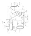
- FIG. 1 is a flow path diagram showing an embodiment of the sample introduction device 100.
- the sample introduction device 100 includes an insertion tube 101, an introduction valve 102, a discharge valve 103, a collection unit 104, a flow path switching valve 105, and the like.
- a sample container 2 in which a sample is enclosed is set in the sample introduction device 100, and the sample (sample gas) vaporized in the sample container 2 is introduced into the gas chromatograph 1.
- the gas chromatograph 1 is a concept including a gas chromatograph mass spectrometer.
- the sample container 2 includes a vial bottle 21 having an opening formed at the upper end portion and a resin septum 22 that closes the opening of the vial bottle 21.
- the sample is sealed in the vial 21.
- the sample is, for example, a solid sample or a liquid sample.
- the insertion tube 101 is composed of, for example, a needle having a sharp tip, and the tip thereof penetrates the septum 22 and is inserted into the vial bottle 21.
- the insertion pipe 101 communicates with the flow path switching valve 105 via the pipe 201.
- the sample container 2 is heated from the outside by a heating unit (not shown), and the sample in the sample container 2 is vaporized.
- the vaporized sample is stored in the upper space (head space 23) in the sample container 2.
- the insertion tube 101 is inserted into the sample container 2 so that its tip is located in the head space 23.
- the sample gas generated by the vaporization of the sample in the sample container 2 is led out from the insertion tube 101 inserted in the head space 23 and sent to the flow path switching valve 105.
- the collecting unit 104 can communicate with the insertion pipe 101 by the operation of the flow path switching valve 105.
- the collection unit 104 is composed of, for example, a sample loop, and collects and concentrates the components in the sample gas derived from the head space 23 of the sample container 2.
- the sample component in the collection unit 104 is volatilized and desorbed, and the sample component is supplied to the gas chromatograph 1 by the carrier gas.
- the flow path switching valve 105 is composed of, for example, a hexagonal valve having six ports a to f.
- the insertion pipe 101 communicates with the port a of the flow path switching valve 105 via the pipe 201. Both ends of the collecting portion 104 communicate with the port b and the port e of the flow path switching valve 105.
- the port c of the flow path switching valve 105 communicates with the gas chromatograph 1 via the pipe 202.
- Carrier gas is supplied to port d of the flow path switching valve 105.
- This carrier gas is an inert gas such as nitrogen gas or helium gas.
- Carrier gas can be supplied to the port f of the flow path switching valve 105 via a pipe (gas supply pipe) 203.
- This carrier gas is an inert gas such as nitrogen gas or helium gas, and is supplied at a pressure different from that of the carrier gas supplied to the port d.
- the pressure of the carrier gas supplied to the ports d and f is pressurized by a pressure regulator (not shown).
- the pipe 203 is branched into the pipe 204 at the branch portion 205.
- the pipe 203 and the pipe 204 can communicate with the insertion pipe 101 by the operation of the flow path switching valve 105.
- the introduction valve 102 is provided on the upstream side of the branch portion 205 in the pipe 203.
- the introduction valve 102 is composed of, for example, an electromagnetic valve.
- the carrier gas is supplied to the port f of the flow path switching valve 105 via the pipe 203.
- the upstream side and the downstream side of the introduction valve 102 in the pipe 203 communicate with each other via a resistance pipe (additional flow path) 206.
- the resistance pipe 206 branches from the pipe 203 on the upstream side of the introduction valve 102 and rejoins the pipe 203 on the downstream side of the introduction valve 102.
- the merging portion of the resistance pipe 206 with respect to the pipe 203 is on the downstream side of the branch portion 205.
- the resistance pipe 206 is a pipe having an inner diameter smaller than that of the pipe 203 constituting the gas supply pipe.
- the pipe 204 can communicate with the pipe (discharge pipe) 207 via the discharge valve 103.
- the discharge valve 103 is composed of, for example, an electromagnetic valve.
- gas can be discharged from the port f of the flow path switching valve 105 to the exhaust port via the pipes 203, 204, and 207.
- the discharge valve 103 is in the closed state, the gas flow between the pipe 204 and the pipe 207 is cut off.
- the gas chromatograph 1 includes a sample introduction unit 11, a column 12, and the like.
- the sample component collected in the collecting unit 104 is supplied to the gas chromatograph 1 via the pipe 202.
- Each sample component supplied to the gas chromatograph 1 together with the carrier gas is introduced into the column 12 from the sample introduction unit 11, and is separated for each sample component in the process of passing through the column 12.
- Each sample component thus separated is detected by a detector (not shown), and a chromatogram is obtained as an analysis result.
- a part of the sample supplied from the collecting unit 104 to the sample introducing unit 11 is discharged to the outside together with the carrier gas, so that the sample is introduced into the column 12 by using the so-called split introduction method. It is supposed to be done.
- the configuration is not limited to this, and the configuration may be such that all the samples supplied from the collection unit 104 to the sample introduction unit 11 are introduced into the column 12.
- Each part such as the insertion tube 101, the collecting part 104, the flow path switching valve 105, and the sample introducing part 11 is arranged in the heating region 3 which is heated to a predetermined temperature.
- the heating region 3 is provided with a heating mechanism (not shown) for heating each part.
- the heating mechanism may be configured to include a heat transfer body such as an aluminum block and a heater. In this case, each of the above parts may be sandwiched between heat transfer bodies, and the heat from the heater may be transferred to each part via the heat transfer body.
- the heating mechanism is not limited to the above configuration, and any other configuration can be adopted.
- the pipes 201 and 202 are arranged in the heating region 3. A part of the pipe 203 on the downstream side of the introduction valve 102 and a part of the pipe 204 on the branch portion 205 side are also arranged in the heating region 3. On the other hand, the introduction valve 102 and the discharge valve 103 are arranged outside the heating region 3 and are used in a state where they are not heated.
- the resistance pipe 206 branched from the pipe 203 on the upstream side of the introduction valve 102 communicates with the pipe 203 in the heating region 3.
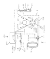
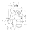
- FIGS. 2A to 2D are flow path diagrams for explaining the operation of the sample introduction device 100.
- the flow path through which the gas flows is indicated by a broken line.
- the sample introduction device 100 introduces the sample vaporized in the sample container 2 into the gas chromatograph 1 by switching the introduction valve 102, the discharge valve 103, and the flow path switching valve 105.
- the introduction valve 102, the discharge valve 103, and the flow path switching valve 105 form a switching mechanism 110 for switching the flow path.
- the port a and the port b of the flow path switching valve 105 communicate with each other, and the port e and the port f communicate with each other. Further, the introduction valve 102 is in the open state, and the discharge valve 103 is in the closed state. Therefore, the carrier gas supplied to the pipe 203 flows into the collecting unit 104 via the ports f and e of the flow path switching valve 105. Then, the carrier gas that has passed through the collecting unit 104 is sent to the insertion pipe 101 via the ports b and a of the flow path switching valve 105 and the pipe 201.
- the port c and the port d of the flow path switching valve 105 communicate with each other.
- the carrier gas is supplied to the column 12 of the gas chromatograph 1 via the ports d and c of the flow path switching valve 105 and the pipe 202.
- the carrier gas supplied from the pipe 203 is supplied into the sample container 2 via the insertion tube 101. ..
- the head space 23 is pressurized to a predetermined pressure. That is, the state of FIG. 2A is a pressurized state in which the carrier gas is supplied from the pipe 203 to the insertion pipe 101. In this pressurized state, the discharge valve 103 puts the insertion pipe 101 and the pipe 207 into a non-communication state.
- the state of FIG. 2B is obtained.
- the pipe 207 constituting the discharge pipe is in a state of communicating with the insertion pipe 101 via the collecting portion 104.
- the sample vaporized in the sample container 2 is led out as a sample gas from the head space 23 to the insertion tube 101 by the pressure in the sample container 2.
- the sample gas led out to the insertion pipe 101 flows into the collection unit 104 via the ports a and b of the pipe 201 and the flow path switching valve 105. Then, the sample gas that has passed through the collecting unit 104 is discharged to the exhaust port via the ports e and f of the flow path switching valve 105 and the pipes 203, 204 and 207.
- the state of FIG. 2B is a derivation state in which the sample gas in the pressurized headspace 23 is led out from the insertion pipe 101 to the pipe 207 via the collecting portion 104. In this lead-out state, the discharge valve 103 communicates the insertion pipe 101 and the pipe 207. In the derivation state, a part of the components in the sample gas passing through the collecting unit 104 is collected by the collecting unit 104.
- the pressure in the head space 23 is high, and the flow rate of the sample gas derived from the head space 23 is also large.
- the pressure in the headspace 23 decreases with the passage of time, and the flow rate of the sample gas passing through the pipes 201, 203, 204, 207 also gradually decreases.
- the introduction valve 102 is opened and the flow path switching valve 105 is switched.
- the port b and the port c of the flow path switching valve 105 communicate with each other, and the port d and the port e communicate with each other.
- the discharge valve 103 is maintained in the open state.
- the carrier gas flows into the collecting unit 104 via the port d and the port e of the flow path switching valve 105. Then, the carrier gas that has passed through the collecting unit 104 is supplied to the gas chromatograph 1 via the ports b and c of the flow path switching valve 105 and the pipe 202. At this time, the components collected in the collecting unit 104 are supplied to the gas chromatograph 1 together with the carrier gas, and each component is separated in the process of passing through the column 12.
- the port a and the port f of the flow path switching valve 105 communicate with each other.
- the carrier gas supplied to the pipe 203 is supplied to the insertion pipe 101 via the ports f and a of the flow path switching valve 105 and the pipe 201.
- FIGS. 2A to 2D as described above may be performed in a state where the sample is contained in the sample container 2 and a state in which the sample is not contained in the sample container 2.
- the sample analysis is performed when the sample is contained in the sample container 2
- the blank analysis is performed when the sample is not contained in the sample container 2.
- the concentration of each component in the sample can be calculated based on the analysis result obtained by the gas chromatograph 1 in the sample analysis and the analysis result obtained by the gas chromatograph 1 in the blank analysis.
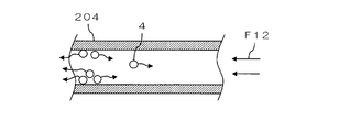
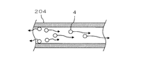
- FIGS. 3A-3C are schematic cross-sectional views for explaining the residual sample components in the pipe 204. As shown in FIG. 3A, a part of the component (molecule) 4 in the sample gas that has passed through the collecting portion 104 may be adsorbed and remain on the inner wall surface of the pipe 204.
- the sample gas passes through the pipe 204 at a high flow velocity as shown by the arrow F11 in FIG. 3A. Therefore, even when the component 4 is adsorbed on the inner wall surface of the pipe 204, the component 4 is unlikely to diffuse upstream with respect to the sample gas.
- the flow velocity of the sample gas becomes very low, so that many components 4 diffuse upstream with respect to the sample gas as shown in FIG. 3C. May be done. In this case, the components remaining in the pipe 204 may diffuse to the collecting portion 104.
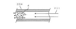
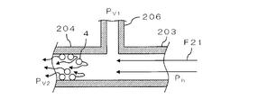
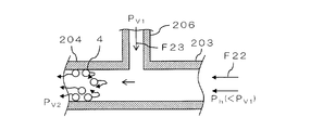
- FIG. 4A to 4C are schematic cross-sectional views for explaining the gas flow around the pipe 204 in the present embodiment.
- a part of the component (molecule) 4 in the sample gas that has passed through the collecting portion 104 may be adsorbed and remain on the inner wall surface of the pipe 204.
- the component 4 in the sample gas is easily adsorbed in the portion of the pipe 204 arranged outside the heating region 3.
- the resistance pipe 206 communicates with the pipe 203 on the collecting portion 104 side of the pipe 204 in the middle of the pipe 203.
- the pressure of the carrier gas in the resistance tube 206 is PV1 .
- the pressure in the pipe 204 is pressurized to a pressure P V2 slightly lower than P V 1 by a pressure regulator (not shown).
- the pressure PV2 may be atmospheric pressure.
- These pressures P V1 and P V2 are lower than the pressure (predetermined pressure) in the head space 23 when pressurized. That is, the resistance pipe 206 supplies gas to the flow path (pipe 203) between the collecting portion 104 and the discharge valve 103 at a pressure lower than the predetermined pressure and higher than the pressure inside the pipe 204.
- the pressure P h in the pipe 203, immediately after deriving the sample gas from the head space 23 is initiated is above a predetermined pressure.
- a predetermined pressure As described above, when the pressure in the head space 23 is high and the flow rate of the sample gas derived from the head space 23 is large, the sample gas passes through the pipe 204 at a high flow velocity as shown by the arrow F21 in FIG. 4A. .. Therefore, even when the component 4 is adsorbed on the inner wall surface of the pipe 204, the component 4 is unlikely to diffuse upstream with respect to the sample gas.
- the pressure P h in the pipe 203 is higher than the pressure P V1 in resistance tube 206, the carrier gas from the resistance tube 206 into the pipe 203 is not flowed.
- the pressure in the head space 23 decreases with time, the pressure P h in the pipe 203 becomes lower than the pressure P V1 in resistance tube 206, the flow rate of the sample gas flowing into the pipe 204 is reduced , As shown by the arrow F22 in FIG. 4B, the flow velocity of the sample gas flowing into the pipe 204 decreases. At this time, as shown by the arrow F23 in FIG. 4B, the carrier gas flows into the pipe 203 from the resistance pipe 206. As a result, it is possible to prevent the component 4 adsorbed on the inner wall surface of the pipe 204 from diffusing upstream with respect to the sample gas.
- the component 4 in the sample gas is adsorbed on the inner wall surface of the pipe 204
- the component 4 in the sample gas may be adsorbed on the inner wall surface of the pipe other than the pipe 204.
- the component 4 in the sample gas may be adsorbed on the inner wall surface of the discharge valve 103 or the like. Since the discharge valve 103 is also arranged outside the heating region 3, the component 4 in the sample gas is easily adsorbed.
- the configuration may be such that gas is supplied into the pipe 203 from an additional flow path other than the resistance pipe 206. That is, the additional flow path is not limited to a bypass flow path that branches from the pipe 203 on the upstream side of the introduction valve 102 and rejoins the pipe 203 on the downstream side of the introduction valve 102.
- a gas source different from the gas source for supplying the carrier gas may be provided, and the gas may be supplied from the gas source into the pipe 203.
- the additional flow path is not limited to the configuration in which the gas is supplied into the pipe 203, and the gas is supplied from an arbitrary position to the flow path between the collection unit 104 and the discharge valve 103. There may be.
- the additional flow path may be configured to supply gas into the pipe 204.
- the switching mechanism 110 for switching the flow path is not limited to the one composed of the introduction valve 102, the discharge valve 103, and the flow path switching valve 105. That is, the configuration and number of valves used in the sample introduction device 100, the configuration of the piping, and the like are not limited to the configuration as in the above embodiment, and may be any other configuration.
- the collecting unit 104 is not limited to a loop-shaped structure such as a sample loop as long as it can collect components in the gas.
- the sample introduction device is An insertion tube that is inserted into the headspace of the sample container, A gas supply tube that can communicate with the insertion tube and pressurizes the head space to a predetermined pressure by supplying gas into the sample container via the insertion tube. A collection unit that can communicate with the insertion tube and collects components in the gas derived from the headspace. An discharge pipe that can communicate with the insertion pipe via the collection part, A pressurized state in which gas is supplied from the gas supply pipe to the insertion pipe, or a derivation in which the pressurized gas in the headspace is led out from the insertion pipe to the discharge pipe via the collection portion.
- the switching mechanism includes a discharge valve in which the insertion pipe and the discharge pipe are in a non-communication state in the pressurized state, and the insertion pipe and the discharge pipe are in a communication state in the lead-out state.
- a discharge valve in which the insertion pipe and the discharge pipe are in a non-communication state in the pressurized state, and the insertion pipe and the discharge pipe are in a communication state in the lead-out state.
- an additional flow path for supplying gas to the flow path between the collection unit and the discharge valve may be provided.
- the additional flow path may supply gas to the flow path between the collection unit and the discharge valve at a pressure lower than the predetermined pressure and higher than the pressure inside the discharge pipe.
- the gas is supplied from the additional flow path at the optimum pressure, so that the components remaining in the middle of the flow path are effectively prevented from diffusing to the collection part side. can do.
- the additional flow path may include a resistance pipe branched from the gas supply pipe.
- the additional flow path can be configured by using the resistance tube branched from the gas supply tube, it is not necessary to separately provide a gas source. Therefore, at low cost, it is possible to prevent the components remaining in the middle of the flow path from diffusing toward the collecting portion.
- the collecting portion is arranged in a heating region and is arranged in a heating region.
- the discharge valve may be located outside the heating region.
- the components in the gas are likely to be adsorbed and remain in the discharge valve arranged outside the heating region and the flow path immediately before the discharge valve. Even in such a case, by supplying gas from the additional flow path to the flow path between the collection part and the discharge valve, the components remaining in the middle of the flow path diffuse to the collection part side. Can be prevented.
- the additional flow path may communicate with the flow path between the collection portion and the discharge valve in the heating region.
- gas can be supplied from the additional flow path to the flow path on the downstream side of the heating region, so that the components remaining in the middle of the flow path are on the collection part side. It can be prevented from spreading.
Landscapes
- Physics & Mathematics (AREA)
- Health & Medical Sciences (AREA)
- Life Sciences & Earth Sciences (AREA)
- Chemical & Material Sciences (AREA)
- Analytical Chemistry (AREA)
- Biochemistry (AREA)
- General Health & Medical Sciences (AREA)
- General Physics & Mathematics (AREA)
- Immunology (AREA)
- Pathology (AREA)
- Sampling And Sample Adjustment (AREA)
Abstract
La présente invention concerne un mécanisme de commutation 110 apte à commuter vers un état sous pression, dans lequel un gaz est fourni à partir d'un tuyau 203 à un tuyau d'insertion 101, ou vers un état principal, dans lequel un gaz sous pression à l'intérieur d'un espace de tête 23 est acheminé depuis le tuyau d'insertion 101 jusqu'à un tuyau 207 par l'intermédiaire d'une partie de capture 104. Une soupape de décharge 103 est incluse dans le mécanisme de commutation 110, la soupape de décharge 103 désactivant la communication entre le tuyau d'insertion 101 et le tuyau 207 dans l'état sous pression et activant une communication entre le tuyau d'insertion 101 et le tuyau 207 dans l'état principal. Un tuyau de résistance 206 fournit le gaz à un trajet d'écoulement entre la partie de capture 104 et la soupape de décharge 103 à l'état principal.
Priority Applications (6)
| Application Number | Priority Date | Filing Date | Title |
|---|---|---|---|
| PCT/JP2019/047647 WO2021111593A1 (fr) | 2019-12-05 | 2019-12-05 | Dispositif d'introduction d'échantillon |
| EP20895813.2A EP4071468A4 (fr) | 2019-12-05 | 2020-11-18 | Dispositif d'introduction d'échantillon |
| PCT/JP2020/043036 WO2021111881A1 (fr) | 2019-12-05 | 2020-11-18 | Dispositif d'introduction d'échantillon |
| US17/641,679 US12222336B2 (en) | 2019-12-05 | 2020-11-18 | Sample introduction device |
| JP2021562559A JP7120471B2 (ja) | 2019-12-05 | 2020-11-18 | 試料導入装置 |
| CN202080054496.4A CN114174821B (zh) | 2019-12-05 | 2020-11-18 | 试样导入装置 |
Applications Claiming Priority (1)
| Application Number | Priority Date | Filing Date | Title |
|---|---|---|---|
| PCT/JP2019/047647 WO2021111593A1 (fr) | 2019-12-05 | 2019-12-05 | Dispositif d'introduction d'échantillon |
Publications (1)
| Publication Number | Publication Date |
|---|---|
| WO2021111593A1 true WO2021111593A1 (fr) | 2021-06-10 |
Family
ID=76221591
Family Applications (2)
| Application Number | Title | Priority Date | Filing Date |
|---|---|---|---|
| PCT/JP2019/047647 Ceased WO2021111593A1 (fr) | 2019-12-05 | 2019-12-05 | Dispositif d'introduction d'échantillon |
| PCT/JP2020/043036 Ceased WO2021111881A1 (fr) | 2019-12-05 | 2020-11-18 | Dispositif d'introduction d'échantillon |
Family Applications After (1)
| Application Number | Title | Priority Date | Filing Date |
|---|---|---|---|
| PCT/JP2020/043036 Ceased WO2021111881A1 (fr) | 2019-12-05 | 2020-11-18 | Dispositif d'introduction d'échantillon |
Country Status (5)
| Country | Link |
|---|---|
| US (1) | US12222336B2 (fr) |
| EP (1) | EP4071468A4 (fr) |
| JP (1) | JP7120471B2 (fr) |
| CN (1) | CN114174821B (fr) |
| WO (2) | WO2021111593A1 (fr) |
Citations (5)
| Publication number | Priority date | Publication date | Assignee | Title |
|---|---|---|---|---|
| US4180389A (en) * | 1978-11-13 | 1979-12-25 | Envirochem Inc. | Isolation and concentration of sample prior to analysis thereof |
| JP2010112761A (ja) * | 2008-11-04 | 2010-05-20 | Shimadzu Corp | 気体試料導入装置及びそれを備えたガスクロマトグラフ装置 |
| JP2011503549A (ja) * | 2007-11-02 | 2011-01-27 | バイオシアス ライフ サイエンシーズ, インコーポレイテッド | 試料注入システム |
| JP2016114456A (ja) * | 2014-12-15 | 2016-06-23 | 株式会社島津製作所 | ヘッドスペースオートサンプラおよびそれを用いたガス分析システム |
| WO2018069959A1 (fr) * | 2016-10-11 | 2018-04-19 | 株式会社島津製作所 | Chromatographe en phase gazeuse |
Family Cites Families (7)
| Publication number | Priority date | Publication date | Assignee | Title |
|---|---|---|---|---|
| WO1991013350A2 (fr) * | 1990-03-02 | 1991-09-05 | Tekmar Company | Dispositif de transport d'analyseur |
| JP3159793U (ja) * | 2010-03-15 | 2010-06-03 | 株式会社島津製作所 | ヘッドスペース試料導入装置 |
| WO2013080333A1 (fr) * | 2011-11-30 | 2013-06-06 | 株式会社島津製作所 | Dispositif d'introduction d'échantillon d'espace libre |
| JP5930049B2 (ja) * | 2012-09-05 | 2016-06-08 | 株式会社島津製作所 | ヘッドスペース試料導入装置とそれを備えたガスクロマトグラフ |
| JP2014059204A (ja) * | 2012-09-18 | 2014-04-03 | Taiyo Nippon Sanso Corp | ガスサンプリング装置 |
| US9588088B2 (en) * | 2013-08-14 | 2017-03-07 | Shimadzu Corporation | Gas sample introduction device |
| JP6225088B2 (ja) * | 2014-09-12 | 2017-11-01 | 株式会社荏原製作所 | 研磨方法および研磨装置 |
-
2019
- 2019-12-05 WO PCT/JP2019/047647 patent/WO2021111593A1/fr not_active Ceased
-
2020
- 2020-11-18 EP EP20895813.2A patent/EP4071468A4/fr active Pending
- 2020-11-18 JP JP2021562559A patent/JP7120471B2/ja active Active
- 2020-11-18 CN CN202080054496.4A patent/CN114174821B/zh active Active
- 2020-11-18 WO PCT/JP2020/043036 patent/WO2021111881A1/fr not_active Ceased
- 2020-11-18 US US17/641,679 patent/US12222336B2/en active Active
Patent Citations (5)
| Publication number | Priority date | Publication date | Assignee | Title |
|---|---|---|---|---|
| US4180389A (en) * | 1978-11-13 | 1979-12-25 | Envirochem Inc. | Isolation and concentration of sample prior to analysis thereof |
| JP2011503549A (ja) * | 2007-11-02 | 2011-01-27 | バイオシアス ライフ サイエンシーズ, インコーポレイテッド | 試料注入システム |
| JP2010112761A (ja) * | 2008-11-04 | 2010-05-20 | Shimadzu Corp | 気体試料導入装置及びそれを備えたガスクロマトグラフ装置 |
| JP2016114456A (ja) * | 2014-12-15 | 2016-06-23 | 株式会社島津製作所 | ヘッドスペースオートサンプラおよびそれを用いたガス分析システム |
| WO2018069959A1 (fr) * | 2016-10-11 | 2018-04-19 | 株式会社島津製作所 | Chromatographe en phase gazeuse |
Also Published As
| Publication number | Publication date |
|---|---|
| JPWO2021111881A1 (fr) | 2021-06-10 |
| US12222336B2 (en) | 2025-02-11 |
| WO2021111881A1 (fr) | 2021-06-10 |
| JP7120471B2 (ja) | 2022-08-17 |
| EP4071468A4 (fr) | 2023-12-27 |
| CN114174821A (zh) | 2022-03-11 |
| EP4071468A1 (fr) | 2022-10-12 |
| US20220326195A1 (en) | 2022-10-13 |
| CN114174821B (zh) | 2023-08-22 |
Similar Documents
| Publication | Publication Date | Title |
|---|---|---|
| US7552618B2 (en) | Chromatographic interface for thermal desorption systems | |
| JP7100766B2 (ja) | ガス濃縮サンプリングのための除水方法、試料導入方法及びそれらの装置 | |
| EP2876438B1 (fr) | Dispositif d'introduction d'échantillon à espace de tête, et chromatographe gazeux équipé de celui-ci | |
| Deans | An improved technique for back-flushing gas chromatographic columns | |
| US9632064B2 (en) | Gas chromatograph system employing hydrogen carrier gas | |
| CN104181245A (zh) | 一种流体包裹体水中氢同位素分析方法 | |
| US9274030B2 (en) | Sample introduction device including channel switching mechanism | |
| CN106662554A (zh) | 分析装置 | |
| CN106093251B (zh) | 用于预浓缩气态样品的方法和设备 | |
| JPH1123550A (ja) | ガスクロマトグラフィの試料供給方法及び装置 | |
| WO2021111593A1 (fr) | Dispositif d'introduction d'échantillon | |
| US20130000485A1 (en) | Flow Control System, Device and Method for Thermal Desorption | |
| CN103760283B (zh) | 一种吸附热解吸进样装置及方法 | |
| US10955389B2 (en) | Sample introduction device for gas chromatograph | |
| CN209841796U (zh) | 一种用于气体浓缩采样的除水装置及进样装置 | |
| US11879878B2 (en) | Gas separation system | |
| JPH04359149A (ja) | 熱分解生成物の分析方法及び装置 | |
| JP3185308B2 (ja) | ガスクロマトグラフ及びこれを用いた分析方法 | |
| CN121844206A (zh) | 用于无排气气相色谱质谱接口的系统和方法 | |
| GB2055608A (en) | Sample injection | |
| JPS62269062A (ja) | ガスクロマトグラフ質量分析装置 |
Legal Events
| Date | Code | Title | Description |
|---|---|---|---|
| 121 | Ep: the epo has been informed by wipo that ep was designated in this application |
Ref document number: 19955205 Country of ref document: EP Kind code of ref document: A1 |
|
| NENP | Non-entry into the national phase |
Ref country code: DE |
|
| 122 | Ep: pct application non-entry in european phase |
Ref document number: 19955205 Country of ref document: EP Kind code of ref document: A1 |
|
| NENP | Non-entry into the national phase |
Ref country code: JP |