WO2021111924A1 - Dispositif de commande hmi, procédé de commande hmi et programme de commande hmi - Google Patents
Dispositif de commande hmi, procédé de commande hmi et programme de commande hmi Download PDFInfo
- Publication number
- WO2021111924A1 WO2021111924A1 PCT/JP2020/043640 JP2020043640W WO2021111924A1 WO 2021111924 A1 WO2021111924 A1 WO 2021111924A1 JP 2020043640 W JP2020043640 W JP 2020043640W WO 2021111924 A1 WO2021111924 A1 WO 2021111924A1
- Authority
- WO
- WIPO (PCT)
- Prior art keywords
- lane
- display
- vehicle
- information
- driving
- Prior art date
- Legal status (The legal status is an assumption and is not a legal conclusion. Google has not performed a legal analysis and makes no representation as to the accuracy of the status listed.)
- Ceased
Links
Images










Classifications
-
- B—PERFORMING OPERATIONS; TRANSPORTING
- B60—VEHICLES IN GENERAL
- B60W—CONJOINT CONTROL OF VEHICLE SUB-UNITS OF DIFFERENT TYPE OR DIFFERENT FUNCTION; CONTROL SYSTEMS SPECIALLY ADAPTED FOR HYBRID VEHICLES; ROAD VEHICLE DRIVE CONTROL SYSTEMS FOR PURPOSES NOT RELATED TO THE CONTROL OF A PARTICULAR SUB-UNIT
- B60W60/00—Drive control systems specially adapted for autonomous road vehicles
- B60W60/001—Planning or execution of driving tasks
- B60W60/0011—Planning or execution of driving tasks involving control alternatives for a single driving scenario, e.g. planning several paths to avoid obstacles
-
- B—PERFORMING OPERATIONS; TRANSPORTING
- B60—VEHICLES IN GENERAL
- B60K—ARRANGEMENT OR MOUNTING OF PROPULSION UNITS OR OF TRANSMISSIONS IN VEHICLES; ARRANGEMENT OR MOUNTING OF PLURAL DIVERSE PRIME-MOVERS IN VEHICLES; AUXILIARY DRIVES FOR VEHICLES; INSTRUMENTATION OR DASHBOARDS FOR VEHICLES; ARRANGEMENTS IN CONNECTION WITH COOLING, AIR INTAKE, GAS EXHAUST OR FUEL SUPPLY OF PROPULSION UNITS IN VEHICLES
- B60K35/00—Instruments specially adapted for vehicles; Arrangement of instruments in or on vehicles
- B60K35/20—Output arrangements, i.e. from vehicle to user, associated with vehicle functions or specially adapted therefor
- B60K35/21—Output arrangements, i.e. from vehicle to user, associated with vehicle functions or specially adapted therefor using visual output, e.g. blinking lights or matrix displays
- B60K35/22—Display screens
-
- B—PERFORMING OPERATIONS; TRANSPORTING
- B60—VEHICLES IN GENERAL
- B60K—ARRANGEMENT OR MOUNTING OF PROPULSION UNITS OR OF TRANSMISSIONS IN VEHICLES; ARRANGEMENT OR MOUNTING OF PLURAL DIVERSE PRIME-MOVERS IN VEHICLES; AUXILIARY DRIVES FOR VEHICLES; INSTRUMENTATION OR DASHBOARDS FOR VEHICLES; ARRANGEMENTS IN CONNECTION WITH COOLING, AIR INTAKE, GAS EXHAUST OR FUEL SUPPLY OF PROPULSION UNITS IN VEHICLES
- B60K35/00—Instruments specially adapted for vehicles; Arrangement of instruments in or on vehicles
- B60K35/20—Output arrangements, i.e. from vehicle to user, associated with vehicle functions or specially adapted therefor
- B60K35/28—Output arrangements, i.e. from vehicle to user, associated with vehicle functions or specially adapted therefor characterised by the type of the output information, e.g. video entertainment or vehicle dynamics information; characterised by the purpose of the output information, e.g. for attracting the attention of the driver
-
- B—PERFORMING OPERATIONS; TRANSPORTING
- B60—VEHICLES IN GENERAL
- B60K—ARRANGEMENT OR MOUNTING OF PROPULSION UNITS OR OF TRANSMISSIONS IN VEHICLES; ARRANGEMENT OR MOUNTING OF PLURAL DIVERSE PRIME-MOVERS IN VEHICLES; AUXILIARY DRIVES FOR VEHICLES; INSTRUMENTATION OR DASHBOARDS FOR VEHICLES; ARRANGEMENTS IN CONNECTION WITH COOLING, AIR INTAKE, GAS EXHAUST OR FUEL SUPPLY OF PROPULSION UNITS IN VEHICLES
- B60K35/00—Instruments specially adapted for vehicles; Arrangement of instruments in or on vehicles
- B60K35/20—Output arrangements, i.e. from vehicle to user, associated with vehicle functions or specially adapted therefor
- B60K35/29—Instruments characterised by the way in which information is handled, e.g. showing information on plural displays or prioritising information according to driving conditions
-
- B—PERFORMING OPERATIONS; TRANSPORTING
- B60—VEHICLES IN GENERAL
- B60K—ARRANGEMENT OR MOUNTING OF PROPULSION UNITS OR OF TRANSMISSIONS IN VEHICLES; ARRANGEMENT OR MOUNTING OF PLURAL DIVERSE PRIME-MOVERS IN VEHICLES; AUXILIARY DRIVES FOR VEHICLES; INSTRUMENTATION OR DASHBOARDS FOR VEHICLES; ARRANGEMENTS IN CONNECTION WITH COOLING, AIR INTAKE, GAS EXHAUST OR FUEL SUPPLY OF PROPULSION UNITS IN VEHICLES
- B60K35/00—Instruments specially adapted for vehicles; Arrangement of instruments in or on vehicles
- B60K35/60—Instruments characterised by their location or relative disposition in or on vehicles
-
- B—PERFORMING OPERATIONS; TRANSPORTING
- B60—VEHICLES IN GENERAL
- B60K—ARRANGEMENT OR MOUNTING OF PROPULSION UNITS OR OF TRANSMISSIONS IN VEHICLES; ARRANGEMENT OR MOUNTING OF PLURAL DIVERSE PRIME-MOVERS IN VEHICLES; AUXILIARY DRIVES FOR VEHICLES; INSTRUMENTATION OR DASHBOARDS FOR VEHICLES; ARRANGEMENTS IN CONNECTION WITH COOLING, AIR INTAKE, GAS EXHAUST OR FUEL SUPPLY OF PROPULSION UNITS IN VEHICLES
- B60K35/00—Instruments specially adapted for vehicles; Arrangement of instruments in or on vehicles
- B60K35/80—Arrangements for controlling instruments
-
- B—PERFORMING OPERATIONS; TRANSPORTING
- B60—VEHICLES IN GENERAL
- B60W—CONJOINT CONTROL OF VEHICLE SUB-UNITS OF DIFFERENT TYPE OR DIFFERENT FUNCTION; CONTROL SYSTEMS SPECIALLY ADAPTED FOR HYBRID VEHICLES; ROAD VEHICLE DRIVE CONTROL SYSTEMS FOR PURPOSES NOT RELATED TO THE CONTROL OF A PARTICULAR SUB-UNIT
- B60W30/00—Purposes of road vehicle drive control systems not related to the control of a particular sub-unit, e.g. of systems using conjoint control of vehicle sub-units
- B60W30/18—Propelling the vehicle
- B60W30/18009—Propelling the vehicle related to particular drive situations
- B60W30/18163—Lane change; Overtaking manoeuvres
-
- B—PERFORMING OPERATIONS; TRANSPORTING
- B60—VEHICLES IN GENERAL
- B60W—CONJOINT CONTROL OF VEHICLE SUB-UNITS OF DIFFERENT TYPE OR DIFFERENT FUNCTION; CONTROL SYSTEMS SPECIALLY ADAPTED FOR HYBRID VEHICLES; ROAD VEHICLE DRIVE CONTROL SYSTEMS FOR PURPOSES NOT RELATED TO THE CONTROL OF A PARTICULAR SUB-UNIT
- B60W50/00—Details of control systems for road vehicle drive control not related to the control of a particular sub-unit, e.g. process diagnostic or vehicle driver interfaces
- B60W50/08—Interaction between the driver and the control system
- B60W50/14—Means for informing the driver, warning the driver or prompting a driver intervention
-
- G—PHYSICS
- G08—SIGNALLING
- G08G—TRAFFIC CONTROL SYSTEMS
- G08G1/00—Traffic control systems for road vehicles
- G08G1/16—Anti-collision systems
-
- B—PERFORMING OPERATIONS; TRANSPORTING
- B60—VEHICLES IN GENERAL
- B60K—ARRANGEMENT OR MOUNTING OF PROPULSION UNITS OR OF TRANSMISSIONS IN VEHICLES; ARRANGEMENT OR MOUNTING OF PLURAL DIVERSE PRIME-MOVERS IN VEHICLES; AUXILIARY DRIVES FOR VEHICLES; INSTRUMENTATION OR DASHBOARDS FOR VEHICLES; ARRANGEMENTS IN CONNECTION WITH COOLING, AIR INTAKE, GAS EXHAUST OR FUEL SUPPLY OF PROPULSION UNITS IN VEHICLES
- B60K2360/00—Indexing scheme associated with groups B60K35/00 or B60K37/00 relating to details of instruments or dashboards
- B60K2360/16—Type of output information
- B60K2360/166—Navigation
-
- B—PERFORMING OPERATIONS; TRANSPORTING
- B60—VEHICLES IN GENERAL
- B60K—ARRANGEMENT OR MOUNTING OF PROPULSION UNITS OR OF TRANSMISSIONS IN VEHICLES; ARRANGEMENT OR MOUNTING OF PLURAL DIVERSE PRIME-MOVERS IN VEHICLES; AUXILIARY DRIVES FOR VEHICLES; INSTRUMENTATION OR DASHBOARDS FOR VEHICLES; ARRANGEMENTS IN CONNECTION WITH COOLING, AIR INTAKE, GAS EXHAUST OR FUEL SUPPLY OF PROPULSION UNITS IN VEHICLES
- B60K2360/00—Indexing scheme associated with groups B60K35/00 or B60K37/00 relating to details of instruments or dashboards
- B60K2360/16—Type of output information
- B60K2360/175—Autonomous driving
-
- B—PERFORMING OPERATIONS; TRANSPORTING
- B60—VEHICLES IN GENERAL
- B60K—ARRANGEMENT OR MOUNTING OF PROPULSION UNITS OR OF TRANSMISSIONS IN VEHICLES; ARRANGEMENT OR MOUNTING OF PLURAL DIVERSE PRIME-MOVERS IN VEHICLES; AUXILIARY DRIVES FOR VEHICLES; INSTRUMENTATION OR DASHBOARDS FOR VEHICLES; ARRANGEMENTS IN CONNECTION WITH COOLING, AIR INTAKE, GAS EXHAUST OR FUEL SUPPLY OF PROPULSION UNITS IN VEHICLES
- B60K2360/00—Indexing scheme associated with groups B60K35/00 or B60K37/00 relating to details of instruments or dashboards
- B60K2360/18—Information management
- B60K2360/186—Displaying information according to relevancy
- B60K2360/1868—Displaying information according to relevancy according to driving situations
-
- B—PERFORMING OPERATIONS; TRANSPORTING
- B60—VEHICLES IN GENERAL
- B60W—CONJOINT CONTROL OF VEHICLE SUB-UNITS OF DIFFERENT TYPE OR DIFFERENT FUNCTION; CONTROL SYSTEMS SPECIALLY ADAPTED FOR HYBRID VEHICLES; ROAD VEHICLE DRIVE CONTROL SYSTEMS FOR PURPOSES NOT RELATED TO THE CONTROL OF A PARTICULAR SUB-UNIT
- B60W50/00—Details of control systems for road vehicle drive control not related to the control of a particular sub-unit, e.g. process diagnostic or vehicle driver interfaces
- B60W50/08—Interaction between the driver and the control system
- B60W50/14—Means for informing the driver, warning the driver or prompting a driver intervention
- B60W2050/146—Display means
-
- B—PERFORMING OPERATIONS; TRANSPORTING
- B60—VEHICLES IN GENERAL
- B60W—CONJOINT CONTROL OF VEHICLE SUB-UNITS OF DIFFERENT TYPE OR DIFFERENT FUNCTION; CONTROL SYSTEMS SPECIALLY ADAPTED FOR HYBRID VEHICLES; ROAD VEHICLE DRIVE CONTROL SYSTEMS FOR PURPOSES NOT RELATED TO THE CONTROL OF A PARTICULAR SUB-UNIT
- B60W2540/00—Input parameters relating to occupants
- B60W2540/215—Selection or confirmation of options
-
- B—PERFORMING OPERATIONS; TRANSPORTING
- B60—VEHICLES IN GENERAL
- B60W—CONJOINT CONTROL OF VEHICLE SUB-UNITS OF DIFFERENT TYPE OR DIFFERENT FUNCTION; CONTROL SYSTEMS SPECIALLY ADAPTED FOR HYBRID VEHICLES; ROAD VEHICLE DRIVE CONTROL SYSTEMS FOR PURPOSES NOT RELATED TO THE CONTROL OF A PARTICULAR SUB-UNIT
- B60W2554/00—Input parameters relating to objects
- B60W2554/40—Dynamic objects, e.g. animals, windblown objects
- B60W2554/406—Traffic density
-
- B—PERFORMING OPERATIONS; TRANSPORTING
- B60—VEHICLES IN GENERAL
- B60W—CONJOINT CONTROL OF VEHICLE SUB-UNITS OF DIFFERENT TYPE OR DIFFERENT FUNCTION; CONTROL SYSTEMS SPECIALLY ADAPTED FOR HYBRID VEHICLES; ROAD VEHICLE DRIVE CONTROL SYSTEMS FOR PURPOSES NOT RELATED TO THE CONTROL OF A PARTICULAR SUB-UNIT
- B60W2710/00—Output or target parameters relating to a particular sub-units
- B60W2710/20—Steering systems
Definitions
- the present disclosure relates to an HMI control device, an HMI control method, and an HMI control program that control an HMI device mounted on a vehicle capable of automatic steering control.
- HMI is an abbreviation for human machine interface.
- the automatic driving device described in Patent Document 1 controls the own vehicle to change lanes to another lane when it detects that the lane in which the own vehicle is traveling is congested.
- the present disclosure provides, for example, a technique that makes it possible to improve the confidence of the occupants of the own vehicle for the result of automatic lane selection or change by the own vehicle.
- the HMI control device is configured to control an HMI device mounted on a vehicle capable of automatic steering control.
- This HMI controller A control status acquisition unit that acquires the execution status of the automatic steering control,
- the driving environment acquisition unit that acquires the driving environment of the vehicle including traffic congestion information,
- An approach status acquisition unit that acquires the approach status of the vehicle into the congestion section included in the congestion information, and
- the execution status is the execution of the automatic steering control in the vehicle and the approach status is the approach of the vehicle into the traffic jam section, the traffic jam information corresponding to the traffic jam section and the vehicle in the vehicle.
- a presentation control unit that presents lane information related to the possibility of lane change by the HMI device, and It has.
- the HMI control device is configured to control an HMI device mounted on a vehicle capable of automatic steering control.
- This HMI controller A control status acquisition unit that acquires the execution status of the automatic steering control,
- the driving environment acquisition unit that acquires the driving environment of the vehicle including traffic information,
- the presentation control unit presents the traffic information and the lane information related to the possibility of lane change in the vehicle by the HMI device. , It has.
- the HMI control method is a method of controlling an HMI device mounted on a vehicle capable of automatic steering control, and includes the following processing or procedure: Acquire the execution status of the automatic steering control and Acquire the driving environment of the vehicle including traffic jam information, Acquire the entry status of the vehicle into the traffic jam section included in the traffic jam information, When the execution status is the execution of the automatic steering control in the vehicle and the approach status is the approach of the vehicle into the traffic jam section, the traffic jam information corresponding to the traffic jam section and the vehicle in the vehicle.
- the lane information related to the possibility of changing lanes is presented by the HMI device.
- the HMI control program is a program executed by an HMI control device configured to control an HMI device mounted on a vehicle capable of automatic steering control.
- the process executed by the HMI control device is The process of acquiring the execution status of the automatic steering control and Processing to acquire the driving environment of the vehicle including traffic jam information, The process of acquiring the entry status of the vehicle into the traffic jam section included in the traffic jam information, and When the execution status is the execution of the automatic steering control in the vehicle and the approach status is the approach of the vehicle into the traffic jam section, the traffic jam information corresponding to the traffic jam section and the vehicle in the vehicle.
- each element may have a reference code in parentheses.
- the reference numeral merely indicates an example of the correspondence between the same element and the specific configuration described in the embodiment described later. Therefore, the present disclosure is not limited to the description of the reference code.
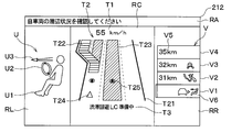
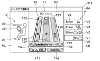
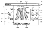
- FIG. 1st operation example of the HMI apparatus shown in FIG. It is the schematic which shows the display example in the 1st operation example of the HMI apparatus shown in FIG.
- the schematic which shows the display example in the 1st operation example of the HMI apparatus shown in FIG. It is the schematic which shows the display example in the 1st operation example of the HMI apparatus shown in FIG.
- FIG. 1st operation example of the HMI apparatus shown in FIG. It is a flowchart which shows the outline of the 1st operation example of the HMI apparatus shown in FIG.
- the in-vehicle system 10 is configured to function as a driving automation system in the vehicle by being mounted on the vehicle as a vehicle.
- a vehicle equipped with the in-vehicle system 10 may be hereinafter referred to as a "own vehicle”.
- the in-vehicle system 10 is configured so that at least automatic steering operation can be realized.
- Auto steering operation means that the driving automation system is in charge of at least steering, that is, the lateral vehicle motion control subtask, among the dynamic driving tasks defined in the standard "SAE J3016" published by SAE International. To execute. SAE is an abbreviation for Society of Automotive Engineers.
- a “dynamic driving task” is all operational and tactical functions that need to be performed in real time when operating a vehicle in road traffic, excluding strategic functions.
- Strategic functions include itinerary planning, waypoint selection, etc.
- automated steering operation is typically an operation automation level corresponding to level 1 or level 2 in “SAE J3016".
- automated steering operation is a concept including so-called “automatic operation” corresponding to any of levels 3 to 5 in “SAE J3016”.
- Automatic driving refers to a driving automation level in which the driving automation system is in charge of, that is, executes all dynamic driving tasks, which corresponds to levels 3 to 5 in “SAE J3016”.
- the level X in “SAE J3016” is hereinafter referred to as "SAE level X”. X is any of 0 to 5.
- the present embodiment is capable of both "high-speed automatic driving” and “traffic jam automatic driving” defined below, and it is also possible to change lanes during these automatic driving. It is assumed that the road transportation system is assumed. That is, in the present embodiment, the in-vehicle system 10 provides the own vehicle with “hands-off driving” corresponding to SAE level 2 and “high-speed automatic driving” and / or “congestion automatic driving” corresponding to SAE level 3. Is configured to be feasible.
- “Hands-off operation” means that the operation automation system automatically executes start, steering, acceleration / deceleration, and stop control on the condition that the driver appropriately responds to the intervention request from the operation automation system.
- a “driver” is an occupant in charge of or performing a dynamic driving task, typically an occupant in the driver's seat of the vehicle, and may also be referred to as a “driver's seat occupant.”
- “High-speed automatic driving” is automatic driving that enables driving in a predetermined high-speed range in a specific section as a limited area specified in “SAE J3016”.
- “High-speed automatic driving” can also be referred to as “high-speed range automatic driving”.
- the "specific section” is a traveling section set in advance to enable automatic driving at SAE level 3, and is typically a predetermined section set on a motorway such as an expressway.
- the predetermined high speed range is, for example, 60 km / h or more and legal speed or less.
- "Traffic jam automatic driving” is an automatic driving that enables driving in a predetermined low speed range in a traffic jam section as the above-mentioned limited area.
- the “congestion section” is a section from the beginning to the end of the congestion line.
- the predetermined low speed range is, for example, less than 60 km / h.
- the in-vehicle system 10 is an in-vehicle network including an in-vehicle communication line 10A and a plurality of nodes connected to each other via the in-vehicle communication line 10A, and various vehicle controls during driving of the own vehicle and various display operations associated therewith. Etc. are configured to be executable.
- the in-vehicle system 10 is configured to comply with a predetermined communication standard such as CAN (international registered trademark: international registration number 1048262A).
- CAN Internationally Registered Trademark
- Controller Area Network is an abbreviation for Controller Area Network.
- the in-vehicle system 10 includes a vehicle state sensor 11, an external state sensor 12, a peripheral monitoring sensor 13, a locator 14, a DCM 15, a navigation device 16, an operation control ECU 17, a DSM 18, an operation unit 19, and an HMI device. It has 20 and.
- DCM is an abbreviation for Data Communication Module.
- ECU is an abbreviation for Electronic Control Unit.
- DSM is an abbreviation for Driver Status Monitor.
- the vehicle condition sensors 11 to the HMI device 20 are connected to each other via the vehicle-mounted communication line 10A.
- the HMI device 20 includes a meter panel 21, a CID device 22, a HUD device 23, and an HMI control device 24.
- CID is an abbreviation for Center Information Display.
- HUD is an abbreviation for head-up display.
- the meter panel 21, the CID device 22, and the HUD device 23 are connected to the HMI control device 24 so as to be capable of information communication via a sub-communication line different from the vehicle-mounted communication line 10A.
- the HMI control device 24 is provided as a node connected to the vehicle-mounted communication line 10A.
- the vehicle state sensor 11 is provided so as to generate outputs corresponding to various quantities related to the driving state of the own vehicle.
- the "driving state-related quantities” include, for example, various quantities related to the driving operation state by the driver or the driving automation system, such as the accelerator operation amount, the brake operation amount, the shift position, the steering angle, and the like.
- the "various quantities related to the driving state” include physical quantities related to the behavior of the own vehicle, such as vehicle speed, angular velocity, front-rear direction acceleration, left-right direction acceleration, and the like.
- the vehicle state sensor 11 provides well-known sensors necessary for vehicle driving control, such as an accelerator opening sensor, a steering angle sensor, a wheel speed sensor, an angular speed sensor, and an acceleration sensor, for simplification of illustration and description. It is a general term for.
- the vehicle condition sensor 11 is provided so as to be able to provide detection output to each part of the operation control ECU 17 and the like via the vehicle-mounted communication line 10A.
- the external state sensor 12 is provided so as to generate an output corresponding to various quantities mainly related to the natural environment in the traffic environment around the own vehicle.
- Various quantities related to the natural environment include, for example, physical quantities such as outside air temperature, rainfall, and illuminance. That is, the external state sensor 12 is a general term for well-known sensors such as an outside air temperature sensor, a raindrop sensor, and an illuminance sensor for the sake of simplification of illustration and description.
- the external world state sensor 12 is provided so as to be able to provide a detection output to each part of the operation control ECU 17 and the like via the vehicle-mounted communication line 10A.
- the peripheral monitoring sensor 13 is provided so as to mainly detect a traffic environment around the own vehicle other than that that can be detected by the external state sensor 12. Specifically, the peripheral monitoring sensor 13 is configured to be capable of detecting moving objects and stationary objects within a predetermined detection range around the own vehicle. “Moving objects” include pedestrians, cyclists, animals, and other vehicles in motion. "Still objects” include roadside structures (eg, walls, buildings, etc.) in addition to road fall objects, guardrails, curbs, parked vehicles, road signs, and road markings. The peripheral monitoring sensor 13 may also be referred to as an "ADAS sensor". ADAS is an abbreviation for Advanced Driver-Assistance Systems.
- the peripheral monitoring sensor 13 has a front camera 131 and a radar sensor 132 as a configuration for detecting moving objects and stationary objects.
- the front camera 131 is provided so as to capture images of the front side and the front side of the own vehicle.
- the front camera 131 is a digital camera device and includes an image sensor such as a CCD or CMOS.
- CCD is an abbreviation for Charge Coupled Device.
- CMOS is an abbreviation for Complementary MOS.
- the radar sensor 132 is a millimeter-wave radar sensor, a submillimeter-wave radar sensor, or a laser radar sensor configured to transmit and receive radar waves, and is mounted on the front surface of a vehicle body of the own vehicle.
- the radar sensor 132 is configured to output a signal corresponding to the position and relative velocity of the reflection point.
- the "reflection point” is a point on the surface of an object existing around the own vehicle, which is presumed to have reflected radar waves.
- the "relative velocity” is the relative velocity of the reflection point, that is, the object reflecting the radar wave, with respect to the own vehicle.
- the locator 14 is configured to determine highly accurate position information and the like of the own vehicle by so-called compound positioning. Specifically, the locator 14 has a GNSS receiver 141, an inertia acquisition unit 142, a high-precision map DB 143, and a locator ECU 144.
- GNSS is an abbreviation for Global Navigation Satellite System.
- DB is an abbreviation for database.
- "High-precision position information" means, for example, a position having SAE level 2 or higher that can be used for advanced driving support or automatic driving, specifically, a position having a position accuracy such that an error is less than 10 cm. Information.
- the GNSS receiver 141 is provided so as to receive positioning signals transmitted from a plurality of positioning satellites, that is, artificial satellites.
- the GNSS receiver 141 is configured to be capable of receiving positioning signals from positioning satellites in at least one of satellite positioning systems such as GPS, QZSS, GLONASS, Galileo, IRNSS, Beidou satellite navigation system, and the like.
- GPS is an abbreviation for Global Positioning System.
- QZSS is an abbreviation for Quasi-Zenith Satellite System.
- GLONASS is an abbreviation for Global Navigation Satellite System.
- IRNSS is an abbreviation for Indian Regional Navigation Satellite System.
- the inertia acquisition unit 142 is configured to acquire the acceleration and the angular velocity acting on the own vehicle.
- the inertia acquisition unit 142 is provided as a 3-axis gyro sensor and a 3-axis acceleration sensor built in the box-shaped housing of the locator 14.
- the high-precision map DB 143 is mainly composed of a non-volatile rewritable memory so as to store the high-precision map information in a rewritable manner and to retain the stored contents even when the power is cut off.
- the non-volatile rewritable memory is, for example, a hard disk, EEPROM, flash ROM, or the like.
- EEPROM is an abbreviation for Electronically Erasable and Programmable ROM.
- ROM is an abbreviation for Read Only Memory.
- the high-precision map information can also be referred to as high-precision map data.
- the high-precision map information includes map information with higher accuracy than the map information used in the conventional car navigation system corresponding to a position error of about several meters.
- the high-precision map DB143 can be used for advanced driving support or automatic driving such as three-dimensional road shape information, lane number information, regulation information, etc., in accordance with a predetermined standard such as the ADASIS standard. Information is stored.
- ADASIS is an abbreviation for Advanced Driver Assistance Systems Interface Specification.
- the locator ECU 144 is configured as a so-called in-vehicle microcomputer provided with a CPU, ROM, RAM, input / output interface, etc. (not shown).
- CPU is an abbreviation for Central Processing Unit.
- RAM is an abbreviation for Random Access Memory.
- the locator ECU 144 sequentially determines the position and direction of the own vehicle based on the positioning signal received by the GNSS receiver 141, the acceleration and angular velocity acquired by the inertia acquisition unit 142, the vehicle speed acquired from the vehicle state sensor 11, and the like. It is configured to determine. Then, the locator 14 is provided so that the determination result of the position, direction, etc. by the locator ECU 144 can be provided to each part of the navigation device 16, the operation control ECU 17, the HMI control device 24, etc. via the vehicle-mounted communication line 10A. ..
- the DCM15 is an in-vehicle communication module, and is provided so that information can be communicated with a base station around the own vehicle by wireless communication conforming to a communication standard such as LTE or 5G.
- LTE is an abbreviation for Long Term Evolution.
- 5G is an abbreviation for 5th Generation.
- DCM15 is configured to acquire the latest high-precision map information from a probe server on the cloud. Further, the DCM15 stores the acquired latest high-precision map information in the high-precision map DB 143 by linking with the locator ECU 144. Further, the DCM15 is configured to acquire traffic information such as traffic congestion information from the probe server and / or a predetermined database.
- the "traffic jam information" includes the position and length of the traffic jam section. Specifically, the traffic jam information includes a traffic jam head position, a traffic jam tail position, an estimated traffic jam distance, an estimated traffic jam time, and the like. Traffic information is also called "road traffic information".
- the navigation device 16 is provided so as to calculate a planned travel route from the current position of the own vehicle to a predetermined destination.
- the navigation device 16 includes a destination set by the driver of the own vehicle, high-precision map information acquired from the locator 14, and position information and direction information of the own vehicle acquired from the locator 14. It is configured to calculate the planned travel route based on.
- the navigation device 16 is provided so that various information including the route information which is the calculation result can be provided to each part of the operation control ECU 17, the HMI control device 24, etc. via the vehicle-mounted communication line 10A. That is, the navigation device 16 displays the navigation screen display on the HMI device 20 for map display, route display, and the like.
- the driving control ECU 17 is provided to control the driving of the own vehicle based on signals and information acquired from the vehicle state sensor 11, the external world state sensor 12, the peripheral monitoring sensor 13, the locator 14, and the like. That is, the operation control ECU 17 is configured to execute a predetermined operation control operation.
- the "predetermined driving control operation” includes a vehicle control operation, that is, a dynamic driving task execution operation corresponding to SAE levels 1 to 3.
- the operation control ECU 17 is configured so that the operation automation level in the own vehicle can be set to any of SAE levels 0 to 3.
- the operation control ECU 17 has a configuration as a so-called in-vehicle microcomputer provided with a CPU, ROM, non-volatile rewritable memory, RAM, input / output interface, etc. (not shown). Specifically, the operation control ECU 17 has an information acquisition unit 171, an operation level determination unit 172, and a vehicle control unit 173 as a functional configuration or a functional unit realized on an in-vehicle microcomputer.
- the information acquisition unit 171 is provided so as to acquire at least the running state of the own vehicle.
- the "driving state” includes a driving state, a traffic environment, and the like detected or acquired by a vehicle state sensor 11, an outside world state sensor 12, a peripheral monitoring sensor 13, and the like. Further, the information acquisition unit 171 is provided so as to acquire the current position of the own vehicle and the traffic information on the road on which the own vehicle is currently traveling. That is, the information acquisition unit 171 acquires information necessary for vehicle control corresponding to SAE levels 1 to 3 from the vehicle state sensor 11, the external world state sensor 12, the peripheral monitoring sensor 13, the locator 14, the DCM 15, and the like. It has become.
- the driving level determination unit 172 is provided so as to set the driving automation level in the own vehicle to any of SAE levels 0 to 3 based on the driving state and the like acquired by the information acquisition unit 171. Specifically, the operation level determination unit 172 determines the success or failure of the start condition of the predetermined operation automation level, and starts the operation automation level when the approval operation by the driver is received while the condition is satisfied. It has become. Further, the operation level determination unit 172 executes the control necessary for terminating the operation automation level when the continuation condition is not satisfied while the operation automation level is being executed.
- the operation control ECU 17 is provided so that the operation automation level setting result by the operation level determination unit 172 can be provided to each unit of the HMI control device 24 and the like via the vehicle-mounted communication line 10A.
- the vehicle control unit 173 is provided to execute a vehicle motion control subtask according to the driving automation level determined by the driving level determination unit 172. That is, when the driving automation level is set to any of SAE levels 1 to 3, the vehicle control unit 173 executes vehicle speed control, steering control, braking control, etc. according to the set driving automation level. It has become like.
- the DSM 18 is provided so as to detect the state of the driver by image recognition based on an image taken by an in-vehicle camera equipped with an image sensor such as a CCD or CMOS. Further, the DSM 18 is configured to give a warning regarding inattentive driving or the like by using a speaker or the like (not shown) provided on the dashboard or the like based on the detection result of the driver's state. Further, the DSM 18 is provided so that the detection result of the driver's state can be provided to each part such as the operation control ECU 17 and the HMI control device 24 via the vehicle-mounted communication line 10A.
- the operation unit 19 is provided so as to accept the manual input operation of the driver.
- the operation unit 19 has a steering wheel 191 and a winker switch 192.
- the steering wheel 191 is fixed to a steering shaft (not shown) that is rotatably supported by a steering column (not shown).
- the blinker switch 192 is configured to output a signal according to the operating state of a blinker lever (not shown), which is an operating lever provided on the steering column.
- the operation unit 19 has a steering switch and the like (not shown).
- the steering switch is provided on a spoke portion (not shown) or the like on the steering wheel 191.
- the operation unit 19 is provided so that the reception result of the input operation by the driver can be provided to each unit such as the operation control ECU 17 and the HMI control device 24 via the vehicle-mounted communication line 10A.
- the HMI device 20 is provided so as to present various information about the own vehicle to the driver at least visually and to accept an input operation of the driver corresponding to the presented contents.
- the HMI device 20 mounted on the own vehicle capable of automatic steering control is configured to be capable of presenting various information related to the automatic steering operation and accepting an input operation by the driver.
- the "information presentation" is, for example, various guidances, input operation instructions, input operation content notifications, warnings, and the like.
- the HMI device 20 includes a meter panel 21, a CID device 22, and a HUD device 23 provided on a dashboard (not shown). That is, in the present embodiment, the HMI device 20 has a configuration as a so-called “dashboard HMI” that is attached to a dashboard (not shown). Further, the HMI device 20 includes a speaker (not shown) for executing information presentation by voice.
- the meter panel 21 has a meter 211, a meter display 212, and a meter switch 213.
- the meter 211 is provided so as to execute meter display such as the vehicle speed of the own vehicle, the cooling water temperature, the remaining fuel amount, and the like.
- the meter display 212 is an information display unit or information display area provided in the central portion of the meter panel 21 in the vehicle width direction, and executes various information displays such as date and time, outside air temperature, mileage, radio receiving station, and the like. It is provided as follows.
- the meter display 212 has a configuration as a display device which is a liquid crystal display or an organic EL display, which has a substantially rectangular displayable area. EL is an abbreviation for electroluminescence.
- the meter switch 213 is provided so as to be able to accept various operations related to the display state or display content on the meter 211 and / or the meter display 212, for example, a trip meter reset operation.
- the CID device 22 is provided on the dashboard.
- the CID device 22 is provided so that the navigation display screen can be displayed for map display, route display, and the like by the navigation device 16. Further, the CID device 22 is provided so as to be able to display information and contents different from the navigation display screen. Specifically, the CID device 22 is configured to be able to execute a display related to a driving mode such as "comfort”, “normal”, “sports", “circuit”, and the like.
- the CID device 22 is configured to be able to execute a display related to the second task that can be used by the driver during the automatic operation of SAE level 3.
- the second task is a task other than the driving operation performed by the driver.
- the second task includes, for example, operation of a mobile communication terminal, viewing of video content, and the like.
- the second task is also referred to as an "out-of-driving task" or "secondary activity".
- the CID device 22 has a CID display 221, an input device 222, and a CID switch 223.
- the CID display 221 is provided so as to be visible to the driver at least at a substantially central position of the dashboard in the vehicle width direction, that is, a position between the driver's seat and the passenger seat.
- the CID display 221 has a configuration as a display device that is a liquid crystal display or an organic EL display.
- the CID display 221 is configured to display an image of the video content on the display device when the second task is viewing the video content.
- the "video content” is, for example, a movie, a concert video, a music video, a television broadcast, or the like.
- the input device 222 is a transparent touch panel, and is provided so as to cover the CID display 221 by being superposed on the CID display 221. That is, the input device 222 is configured to be able to accept an input operation by the driver or the like corresponding to the display while allowing the driver or the like to visually recognize the display on the CID display 221.
- the CID switch 223 has a plurality of manually operated switches arranged around the CID display 221 and the input device 222.
- the HUD device 23 is provided so as to display a display image including characters and / or symbols in front of the driver. That is, the HUD device 23 is configured to superimpose and display the display image on the foreground including the road surface where the own vehicle is traveling by forming a virtual image display image in front of the driver's seat using AR technology.
- the "superimposition display" in the HUD device 23 means that related information (for example, a building name) of a superimposing object (for example, a building) included in the foreground is displayed so as to overlap the superimposing object or displayed in the vicinity of the superimposing object. By doing so, it means displaying the superimposed object and related information while associating them with each other. Route display, traveling direction display, traffic information display, etc.
- the HUD device 23 projects the display image light constituting the display image onto a predetermined projection range of the front windshield (not shown), and visually recognizes the reflected light of the display image light by the front windshield to the driver. By making it, the display image is AR-displayed.
- HMI control device Referring to FIG. 1 again, the HMI control device 24 is provided to control the operation of the HMI device 20. That is, the HMI control device 24 has a configuration as an HCU that controls the operation of the meter panel 21, the CID device 22, the HUD device 23, and the like included in the HMI device 20. HCU is an abbreviation for HMI Control Unit.
- the HMI control device 24 has a configuration as a so-called in-vehicle microcomputer provided with a CPU, ROM, non-volatile rewritable memory, RAM, input / output interface, etc. (not shown).
- the HMI control device 24 has the following functional configuration or functional unit realized on a microcomputer. That is, the HMI control device 24 includes a vehicle information acquisition unit 241, a control status acquisition unit 242, a driving environment acquisition unit 243, an approach status acquisition unit 244, a presentation control unit 245, an operation reception unit 246, and a second task. It has a control unit 247.
- the vehicle information acquisition unit 241 is provided to acquire information related to the driving state of the own vehicle. Specifically, the vehicle information acquisition unit 241 acquires various quantities related to the driving state of the own vehicle, which are detected or acquired by the vehicle state sensor 11. Further, the vehicle information acquisition unit 241 acquires the detection result of the driver's behavior by the DSM 18.
- the control status acquisition unit 242 is provided to acquire the execution status of the automatic steering control in the own vehicle. Specifically, the control status acquisition unit 242 acquires the result of determination or setting of the operation automation level by the operation level determination unit 172 from the operation control ECU 17.
- the driving environment acquisition unit 243 is provided to acquire the driving environment of the own vehicle including the traffic jam information. Specifically, the traveling environment acquisition unit 243 acquires the traffic environment around the own vehicle, which is detected or acquired by the external world state sensor 12 and the peripheral monitoring sensor 13. Further, the traveling environment acquisition unit 243 acquires the current position of the own vehicle, the planned traveling route, and the traffic information on the planned traveling route from the locator 14 and the navigation device 16.
- the approach status acquisition unit 244 is provided to acquire the approach status of the own vehicle into the traffic jam section included in the traffic jam information. Specifically, the approach status acquisition unit 244 determines whether or not the vehicle has entered the congested section based on the traffic environment around the vehicle, congestion information, and the current position acquired by the driving environment acquisition unit 243. judge.
- the term "approach” as used herein includes both the case where the own vehicle is lined up at the end of the traffic jam line and starts the traffic jam, and the case where the own vehicle is actually in the traffic jam line. ..
- the presentation control unit 245 is provided to control the information presentation operation by the HMI device 20. That is, the presentation control unit 245 presents various information to the occupants of the own vehicle including the driver by controlling the image output and the audio output in the meter panel 21, the CID device 22, and the HUD device 23. ing. "Various information" includes route information, traffic jam information, various messages, and the like.
- the operation reception unit 246 is provided so as to receive an input operation in the HMI device 20 by the occupants of the own vehicle including the driver. Specifically, the operation reception unit 246 acquires or monitors the reception status or reception result of the input operation by the meter switch 213, the input device 222, or the CID switch 223 corresponding to various information presented by the presentation control unit 245. It is designed to do.
- the second task control unit 247 is provided to control the use or execution of the second task by the HMI device 20. Specifically, the second task control unit 247 has a second task in the CID device 22 based on the operation automation level acquired by the control status acquisition unit 242 and the input operation acceptance result acquired by the operation reception unit 246. It is designed to control the output state of the content.
- the information acquisition unit 171 in the operation control ECU 17 acquires various information including the running state of the own vehicle. Specifically, the information acquisition unit 171 acquires the driving state and traffic environment of the own vehicle from the vehicle state sensor 11, the outside world state sensor 12, and the peripheral monitoring sensor 13. In addition, the information acquisition unit 171 acquires the current position of the own vehicle, the planned travel route, and the traffic information on the planned travel route from the locator 14 and the navigation device 16. Further, the information acquisition unit 171 acquires the driver's state from the DSM 18. In addition, the information acquisition unit 171 acquires the operation state of the operation unit 19 and the HMI device 20 by the driver or the like.
- the operation level determination unit 172 determines the start condition of the operation automation level corresponding to SAE levels 1 to 3 based on various information such as the running state acquired by the information acquisition unit 171. When the start condition of the predetermined operation automation level is satisfied, the operation level determination unit 172 determines the execution of the operation automation level. Then, the vehicle control unit 173 executes vehicle speed control, steering control, braking control, and the like according to the driving automation level determined by the driving level determination unit 172.
- the "traffic condition" includes the road condition corresponding to the traffic information such as the traffic jam information in addition to the traffic environment around the own vehicle. Therefore, during the hands-off operation, the driver is not required to hold the steering wheel 191 at all times, but needs to maintain a posture capable of immediately changing the driving.
- the operation control ECU 17 does not try to change lanes for avoiding traffic jams even if the own vehicle approaches the end of the traffic jam, or conversely, the own vehicle dares to go to the end of the traffic jam. You may try to change lanes in line with. Specifically, for example, while driving on a left-hand traffic road with three lanes on each side, there is a long traffic jam that makes it difficult to see to the intersection where the right turn is planned, only in the right-turnable lane closest to the center of the road. Is assumed.
- the own vehicle does not try to change lanes from the congested right turnable lane to another driving lane, or changes lanes from another driving lane to a congested right turnable lane. You may try.
- a motorway that is a left-hand traffic road with three lanes on each side, it is assumed that there is congestion from the branch guidance lane to an interchange or the like to the leftmost driving lane on the main lane, that is, the first driving lane.
- a "branch guidance lane” is a branch road that branches off from the main lane at an interchange, that is, runs parallel to the main lane between the driving lane and the shoulder of the main lane in order to connect the rampway and the main lane.
- Interchange, etc. includes junctions, parking areas, and service areas.
- the own vehicle may try to change lanes to the first lane in which congestion is occurring during high-speed automatic driving in the second lane.
- the occupants of the own vehicle including the driver may wonder why the own vehicle is bothered to line up at the end of the traffic jam.
- the driver may not pay sufficient attention to the immediate driving conditions of the vehicle and / or the traffic conditions around the vehicle while using the second task.
- the vehicle-mounted system 10 is more familiar with the artificial selection according to the tastes or circumstances of the occupants including the driver than the automatic selection.
- the control status acquisition unit 242 acquires the execution status of the automatic steering control.
- the traveling environment acquisition unit 243 acquires the traveling environment of the own vehicle including the traffic jam information.
- the approach status acquisition unit 244 acquires the approach status of the own vehicle to the traffic jam section included in the acquired traffic jam information.
- the presentation control unit 245 controls the information presentation operation by the HMI device 20 according to the acquisition results by the control status acquisition unit 242, the traveling environment acquisition unit 243, and the approach status acquisition unit 244.
- the presentation control unit 245 presents the traffic jam information corresponding to the traffic jam section and the lane information related to the possibility of lane change in the own vehicle by the HMI device 20 in a predetermined case.
- the execution status of the automatic steering control acquired by the control status acquisition unit 242 is executing the automatic steering control in the own vehicle, and the approach status acquired by the approach status acquisition unit 244 is congested. This is the case when the vehicle is entering the section.
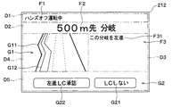
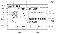
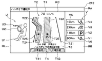
- the presentation control unit 245 has a first display area D1, a second display area D2, a third display area D3, and a fourth display in the meter display 212. Various information is displayed in each of the area D4 and the fifth display area D5.
- the first display area D1 is an elongated strip-shaped area extending in the horizontal direction at the uppermost portion of the display screen of the meter display 212 (hereinafter, simply referred to as “display screen”).
- the first display area D1 is provided over the entire width of the display screen.
- the status display F1 is displayed in the first display area D1.
- the status display F1 is a display showing information corresponding to the execution status of the automatic steering control. Specifically, during high-speed automatic operation, as shown in FIGS. 2 to 5, the status display F1 by the text display “during high-speed automatic operation" is displayed. On the other hand, during the automatic traffic jam driving, the status display F1 by the text display "During automatic traffic jam driving" is displayed. Further, during the hands-off operation, the status display F1 by the text display "Hands-off operation in progress" is displayed.
- the second display area D2 is an elongated strip-shaped area at the upper part of the display screen, which is arranged adjacent to the first display area D1 below the first display area D1.
- the second display area D2 is provided over the entire width of the display screen.
- the short-distance information display F2 is displayed in the second display area D2.
- the short-distance information display F2 is a display showing traffic information to be noted such as traffic congestion information within a predetermined short-distance range (for example, within 3 km) from the own vehicle.
- the short-distance information display F2 by the text display "500 m ahead with branch” is displayed. If there is a branch 500 m ahead of the vehicle in the direction of travel and there is congestion from the front side of this branch to the branch guidance lane, as shown in FIG. 3, "500 m ahead congestion before the branch”.
- the short-distance information display F2 by the text display "" is displayed.
- the text display "500 m ahead ** IC exit” is displayed as shown in FIGS. 4 and 5.
- the short-distance information display F2 is displayed. "**" is an abbreviation for the name of the exit interchange.
- the third display area D3 is a rectangular area provided on the right side of the display screen and at the center in the vertical direction.
- the third display area D3 is provided over a width substantially half of the total width of the display screen.
- the main information display F3 is displayed in the third display area D3.
- the main information display F3 includes a traveling direction display F31, an exit information display F32, and a caution information display F33.
- the traveling direction display F31 is a display indicating the traveling direction of the own vehicle at the branch or exit interchange when the short-distance information display F2 regarding the branch or exit interchange is displayed in the second display area D2. Specifically, for example, it is assumed that the own vehicle is approaching a junction having a branch and goes straight on the main lane without proceeding to the branch guidance lane at the junction. In this case, as shown in FIGS. 2 and 3, the traveling direction display F31 by the text display "This branch goes straight" is displayed. On the other hand, when the own vehicle is approaching the exit interchange, as shown in FIGS. 4 and 5, the traveling direction display F31 by the text display "I will exit at this exit" is displayed.
- Exit information display F32 is a display showing information related to the exit interchange. Specifically, the exit information display F32 indicates the mileage to the exit interchange and the name of the exit interchange.
- the caution information display F33 is a text display indicating a traffic jam and the possibility of a lane change related to the traffic jam, and corresponds to the traffic jam information and the lane information. Specifically, for example, it is assumed that the own vehicle is approaching a junction having a branch, does not proceed to the branch road at the junction, and goes straight on the main lane with three lanes on each side. Further, it is assumed that the own lane, which is the lane in which the own vehicle is currently traveling, is the first driving lane on the shouldermost side, that is, the leftmost side of the main lane.
- the fourth display area D4 is a rectangular area provided on the left side of the display screen and at the center in the vertical direction.
- the fourth display area D4 is provided over a width substantially half of the total width of the display screen.
- the graphic road display G1 is displayed in the fourth display area D4.
- the graphic road display G1 is a graphic display showing a traffic jam and a possibility of a lane change related to the traffic jam, and corresponds to the traffic jam information and the lane information.
- the graphic road display G1 includes a graphic lane display G11, a graphic route display G12, and a graphic traffic information display G13.
- the graphic lane display G11 is a graphic display showing the lane arrangement and the branch structure in the road width direction within a predetermined short distance range from the own vehicle, which is the destination of the own vehicle on the road on which the own vehicle is currently traveling. ..
- the graphic lane display G11 is displayed with a sense of perspective so that the traveling direction of the own vehicle is from the lower side to the upper side of the display screen and the lane width becomes narrower as the distance from the own vehicle increases.
- the graphic route display G12 is a route guidance graphic display that shows the planned travel route of the own vehicle in lane units on the graphic lane display G11.
- the route guidance graphic display is a strip-shaped or thick line-shaped graphic display drawn along the extending direction of the lane displayed on the graphic lane display G11.
- the graphic route display G12 indicates the own lane by the front side portion, that is, the lowermost portion closest to the own vehicle. Further, as shown in FIGS. 3 to 5, the graphic route display G12 changes lanes when a lane change is planned on the planned travel route or when a lane change is recommended from the current traffic conditions. It is displayed in a refracted or branched manner depending on the possibility of.
- the portion corresponding to the normal traveling section where no congestion has occurred is displayed in a normal display composed of a normal color and / or a normal pattern.
- the "normal color” is a color different from the warning color, for example, white or black.
- the "warning color” is a type of color that attracts the attention of the observer, that is, the occupant of the vehicle, such as red, yellow, and the like.
- the "warning color” can also be referred to as the "caution color”.
- the "normal pattern” is a pattern of a type different from the warning pattern, and is, for example, a continuous pattern such as a solid line or a non-blinking pattern.
- the "warning pattern” is a type of pattern that attracts the attention of the observer, and is, for example, an intermittent pattern such as a dotted line or blinking.
- the "warning pattern” may also be referred to as a "caution pattern”.
- the graphic route display G12 the portion corresponding to the congested section is displayed in a warning display consisting of a warning color and / or a warning pattern.
- the graphic route display G12 displayed as a warning also corresponds to the graphic traffic information display G13 described later.
- the graphic traffic information display G13 is a graphic display showing traffic information on the graphic lane display G11.
- the graphic traffic information display G13 corresponding to the lane regulation due to construction work or the like is displayed as a figure similar to a traffic sign for closing vehicles as shown in FIG.
- the graphic traffic information display G13 corresponding to the lane in the traffic jam is displayed as a warning display in the graphic route display G12 or a similar route guidance graphic display.
- the fifth display area D5 is an elongated strip-shaped area extending in the horizontal direction at the bottom of the display screen.
- the fifth display area D5 is provided over the entire width of the display screen.
- the guidance information display F5 and the operation button display G2 are displayed.
- Guidance information display F5 is a text display showing various guidance information related to automatic steering operation. Specifically, for example, when the hands-off operation can be started, the guidance information display F5 indicates that the hands-off operation can be started. The same applies when high-speed automatic driving or traffic jam automatic driving can be started.
- the guidance information display F5 is displayed in the fifth display area D5 together with the operation button display G2, the guidance information display F5 corresponds to the presentation of the input request related to the displayed operation button display G2.
- the operation button display G2 is an operation button-like graphic display displayed below the position where the guidance information display F5 is displayed.
- the operation button display G2 is displayed in the fifth display area D5 together with the guidance information display F5, the operation button display G2 is arranged adjacent to the guidance information display F5 below the guidance information display F5.
- At least one operation button display G2 may be displayed or hidden depending on the situation. Specifically, for example, as shown in FIGS. 2 and 3, a plurality of operation button displays G2 including the first operation button display G21 and the second operation button display G22 can be displayed. Alternatively, as shown in FIGS. 4 and 5, only the first operation button display G21 may be displayed.
- FIGS. 2 to 5 specific examples of information presentation corresponding to various situations or cases encountered by the own vehicle will be shown with reference to FIGS. 2 to 5.
- the presentation control unit 245 displays the status display F1 by the text display "during high-speed automatic operation" in the first display area D1.
- audio output corresponding to the information display shall be appropriately executed as necessary.
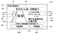
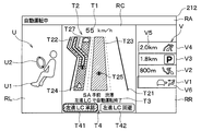
- FIG. 2 shows an example of information presentation when the own vehicle is approaching the end of the traffic jam that is occurring under the following conditions.
- -The own vehicle is approaching a junction with a branch during high-speed autonomous driving.
- -On the planned travel route the own vehicle does not proceed to the branch road side at the junction, but goes straight on the main road.
- -The own vehicle is traveling in the first lane on the leftmost side of the main lane, that is, on the branch guidance lane side.
- -Two lanes near the center of the road, that is, near the median strip are restricted by construction work on the main lane, causing congestion at the destination in the own lane.
- the presentation control unit 245 displays the short-distance information display F2 by the text display "500 m ahead with branching" in the second display area D2. Further, the presentation control unit 245 displays the traveling direction display F31 by the text display "This branch goes straight", the exit information display F32, and the text display "Progress destination straight ahead construction congestion” in the third display area D3. Attention information display F33 is displayed.
- the presentation control unit 245 presents the lane keeping information as lane information.
- "Lane maintenance information” is information indicating that although it is possible to change lanes safely and easily, it is recommended to maintain driving in the own lane without changing lanes.
- the presentation control unit 245 keeps its own lane and goes straight ahead without changing lanes to the branch guidance lane in the third display area D3. Display that there is a traffic jam in the direction.
- the presentation control unit 245 performs the following display on the graphic lane display G11 in the fourth display area D4. That is, the presentation control unit 245 sets the portion of the linear graphic route display G12 extending on the own lane on the side separated from the own vehicle as a warning display, and serves as the graphic traffic information display G13 indicating the congested section. Display it.
- the presentation control unit 245 does not display the graphic route display G12 in the branch guidance lane. This allows the driver to understand the reason why the lane change control is not performed even if the own vehicle reaches the end of the traffic jam occurring at the destination of the own lane.
- the presentation control unit 245 displays the guidance information display F5 by the text display "Automatic driving can be used even during traffic jams" in the fifth display area D5. Further, the presentation control unit 245 displays the first operation button display G21 having the text display "manual operation” and the second operation button display G22 having the text display "automatic operation” in the fifth display area D5. Display it.
- the guidance information display F5 corresponds to an input request presentation, that is, an input request display, which prompts the user to select and perform an input operation by selecting either the first operation button display G21 or the second operation button display G22.
- the presentation control unit 245 executes the input request presentation that prompts the input operation corresponding to the presented lane information.
- the driver uses, for example, a meter switch 213 or a steering switch (not shown) provided on the steering wheel 191 to select either the first operation button display G21 or the second operation button display G22. You can perform the operation.
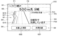
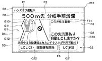
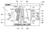
- FIG. 3 shows an example of information presentation when approaching the end of the traffic jam that is occurring under the following conditions.
- -The own vehicle is approaching a junction with a branch during high-speed autonomous driving.
- -On the planned travel route the own vehicle does not proceed to the branch road side at the junction, but goes straight on the main road.
- -The own vehicle is traveling in the first driving lane on the main road.
- ⁇ There is congestion in the branch guidance lane and the branch road beyond it, and the end of the congestion reaches the own lane.
- Congestion in the own lane has been resolved in the middle of the parallel running section with the branch guidance lane.
- -No traffic congestion has occurred in the two lanes on the right side of the own lane, that is, on the median strip side.
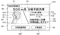
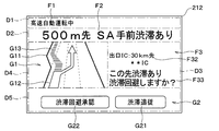
- the presentation control unit 245 displays the short-distance information display F2 by the text display "500 m ahead, traffic jam before branching" in the second display area D2. Further, the presentation control unit 245 displays the traveling direction display F31 and the exit information display F32 by the text display "This branch goes straight" in the third display area D3.
- the presentation control unit 245 presents the lane change information as lane information.
- “Lane change information” is information indicating that it is possible to change lanes safely and easily and that it is recommended to change lanes.
- the presentation control unit 245 causes the branch guidance lane to display the graphic traffic information display G13 indicating the congested section. Further, the presentation control unit 245 displays the front end of the graphic traffic information display G13 indicating the congested section extending from the branch guidance lane at an intermediate position on the linear graphic route display G12 extending on the own lane. Of the graphic route display G12 on the own lane, the intermediate portion corresponding to the end of the traffic jam is displayed as a warning as the graphic traffic information display G13 indicating the traffic jam section, while the remaining portion is normally displayed. As a result, the driver can recognize that the congestion in the own lane is temporary and that the congestion in the own lane is eliminated in the middle of the parallel running section with the branch guidance lane.
- the presentation control unit 245 performs the following display on the graphic lane display G11 in the fourth display area D4. That is, the presentation control unit 245 indicates the possibility of changing lanes by displaying the arrow-shaped route guidance graphic display extending from the end of the normal display portion on the front side of the graphic route display G12 toward the front right. Displayed as an additional graphic path display G12. Further, the presentation control unit 245 displays the caution information display F33 by the text display "Do you want to avoid the traffic jam before the branch?" In the third display area D3. As a result, the driver can recognize that the end of the traffic jam, which has reached the destination of the own vehicle in the own lane, can be avoided by changing lanes.
- the presentation control unit 245 has a first operation button display G21 having a text display of "traffic jam tracking" and a second operation button display G22 having a text display of "traffic jam avoidance approval" in the fifth display area D5. Is displayed.
- the caution information display F33 corresponds to the presentation of an input request prompting the user to select and perform an input operation by selecting either the first operation button display G21 or the second operation button display G22. In this way, the presentation control unit 245 executes the input request presentation that prompts the input operation corresponding to the presented lane information.
- the second task control unit 247 limits the use of the second task from the start of the display of the operation button display G2 until the input operation is accepted by the operation reception unit 246. Specifically, for example, the second task control unit 247 reduces the display area of the second task content on the CID display 221 while prominently displaying a message prompting forward gaze and an input operation. Alternatively, for example, the second task control unit 247 suspends the use of the second task.
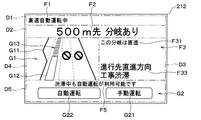
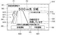
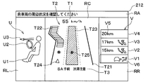
- FIG. 4 shows an example of information presentation when approaching the end of the traffic jam that is occurring under the following conditions.
- Your vehicle is approaching the exit interchange.
- the own vehicle is traveling in the first driving lane on the main road.
- ⁇ There is a traffic jam in the branch guidance lane for exiting the motorway at the exit interchange, and the end of the traffic jam reaches the own lane.
- Congestion in the own lane has been resolved in the middle of the parallel running section with the branch guidance lane.
- -No traffic congestion has occurred in the two lanes to the right of the own lane, that is, the second driving lane and the overtaking lane.
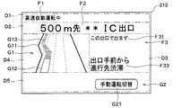
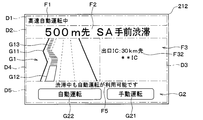
- the presentation control unit 245 displays the short-distance information display F2 by the text display "500 m ahead ** IC exit" in the second display area D2.
- the presentation control unit 245 has a traveling direction display F31 with a text display of "exit at this exit” and a caution information display F33 with a text display of "traffic jam ahead of the exit” in the third display area D3. Is displayed.
- the presentation control unit 245 presents the lane keeping information as lane information.
- the presentation control unit 245 performs the following display on the graphic lane display G11 in the fourth display area D4. That is, the presentation control unit 245 displays the graphic route display G12 extending from the own lane to the branch guidance lane.
- the presentation control unit 245 sets the portion of the graphic route display G12 on the front side that displays the own lane as a normal display.
- the presentation control unit 245 sets the portion of the graphic route display G12 on the destination side of the normal display portion as a warning display and displays it as the graphic traffic information display G13 indicating the congested section. This allows the driver to understand the reason why the lane change control is not performed even if the own vehicle reaches the end of the traffic jam occurring at the destination of the own lane.
- the lane change from the own lane to the branch guidance lane in a traffic jam is preset in the planned travel route. That is, such a lane change is not an unplanned lane change. Therefore, in the example of FIG. 4, the message for lane change approval and the operation button display G2 are not displayed.
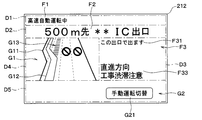
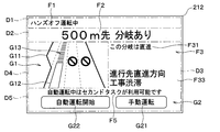
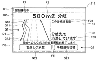
- FIG. 5 shows an example of information presentation when approaching the end of the traffic jam that is occurring under the following conditions.
- Your vehicle is approaching the exit interchange.
- the own vehicle is traveling in the first driving lane on the main road.
- ⁇ On the main lane lane restrictions have been imposed due to construction work after the section running parallel to the branch guidance lane, causing traffic congestion.
- the end of the traffic jam reaches the section in the own lane in front of the own vehicle and parallel to the branch guidance lane.
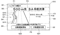
- the presentation control unit 245 displays the short-distance information display F2 by the text display "500 m ahead ** IC exit” in the second display area D2.
- the presentation control unit 245 displays the traveling direction display F31 by the text display “exit at this exit” and the caution information display F33 by the text display "straight direction construction congestion caution” in the third display area D3. Display it.
- the presentation control unit 245 presents the lane change information as lane information. That is, the presentation control unit 245 displays the graphic route display G12 indicating that the vehicle changes from its own lane to the branch guidance lane and proceeds in the branch guidance lane in the fourth display area D4 in the normal display.
- the presentation control unit 245 performs the following display on the graphic lane display G11 in the fourth display area D4. That is, the presentation control unit 245 displays the graphic traffic information display G13 indicating the congested section in the parallel running section with the branch guidance lane in the own lane. As a result, the graphic traffic information display G13 indicating the congested section is displayed at a position on the own lane on the side away from the own vehicle. Further, the presentation control unit 245 displays the graphic traffic information display G13 having a graphic shape similar to the traffic sign of the vehicle closed at a position corresponding to the restricted lane.
- the presentation control unit 245 displays the first operation button display G21 having the text display "manual operation switching" in the fifth display area D5.
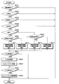
- FIG. 6 shows the flow of information presentation operation regarding lane change during automatic driving by the CPU in the HMI control device 24.
- the CPU in the HMI control device 24 is simply abbreviated as "CPU”.
- step 601 the CPU determines whether or not it is currently in automatic operation.
- step 601 NO
- the CPU skips all the processes after step 602 and ends this operation.
- step 601 YES
- the CPU advances the process to step 602.
- step 603 the CPU determines the entry status of the own vehicle into the traffic jam section included in the acquired traffic jam information. That is, the CPU determines whether or not the own vehicle has entered the congested section.
- the approach status is, for example, all or one of the current position of the own vehicle, traffic congestion information, the distance between the own vehicle and the preceding vehicle, the decrease in the vehicle speed of the own vehicle and / or the preceding vehicle, the hazard lamp lighting of the preceding vehicle, and the like. It is possible to make a judgment based on the part.
- the CPU skips all the processes after step 604 and ends this operation.
- the CPU advances the process to step 604.
- step 604 the CPU determines whether or not there is a branch in the congested section.
- the term "branch” as used herein includes both a branch with a branch road at an interchange and a branch at a junction. In the determination of step 604, unlike step 605 described later, it does not matter whether the own vehicle plans to proceed in the branch guidance lane or the main lane at such a branch.
- step 604 NO
- step 604 YES
- step 605 the CPU determines whether the own vehicle is scheduled to proceed to the branch road side or the main road at the branch determined to exist in step 604.
- step 605 YES
- step 606 the CPU advances the process to step 606.
- step 605 NO
- step 606 the CPU determines whether or not the branch destination is congested.
- the CPU advances the process to step 611.
- the CPU advances the process to step 612.
- the CPU depends on whether or not the own vehicle advances to the branch road side, whether or not the branch destination is congested, and whether or not it is possible to avoid congestion by changing lanes. And present information about traffic jams, branches, and lane changes.
- step 611 the CPU presents the lane keeping information and the course congestion information by the HMI device 20 as shown in FIG.
- the graphic route display G12 which is the route guidance graphic display of the normal display and the portion on the own lane in the graphic traffic information display G13 which is the route guidance graphic display of the warning display in FIG. 4 are on the own lane. Corresponds to continuous display with.
- Congese congestion information is congestion information corresponding to a congestion section where the own vehicle is traveling on the planned travel route and the own vehicle needs to travel.
- the course congestion information corresponds to the graphic traffic information display G13 in FIG. 4 and the caution information display F33 "from the front of the exit to the destination congestion".
- step 612 the CPU presents the lane change information and the traffic jam caution information by the HMI device 20 as shown in FIG.
- the lane change information corresponds to the graphic route display G12 of the normal display, which indicates in FIG. 5, that the lane is changed from the own lane to the branch guidance lane and the vehicle travels in the branch guidance lane.
- the "traffic jam caution information” is traffic jam information different from the above-mentioned course traffic jam information, and is information for calling attention to the fact that a traffic jam is occurring in front of the own vehicle.
- the traffic jam caution information corresponds to the caution information display F33 in FIG. 5 indicating "straight ahead construction congestion caution" and the graphic traffic information display G13 indicating the traffic jam section displayed in the parallel running section with the branch guidance lane in the own lane. ..
- the CPU executes the process of step 613.
- the CPU presents the lane change information and the traffic jam caution information by the HMI device 20 as shown in FIG.
- the lane change information corresponds to an additional graphic route display G12 in the shape of an arrow extending toward the front right in FIG.
- the traffic jam caution information corresponds to the caution information display F33 of "traffic jam before branching" and the graphic traffic information display G13 showing the traffic jam section from the branch guidance lane to the own lane in FIG.
- the CPU executes the process of step 614. To do.
- the CPU presents the lane keeping information and the course congestion information by the HMI device 20 as shown in FIG.
- the lane keeping information is a route guidance graphic display indicating that the own vehicle is lined up at the end of the traffic jam occurring in the own lane by the continuation of the graphic route display G12 and the graphic traffic information display G13 in FIG. Correspond.
- the course congestion information corresponds to the caution information display F33 in FIG. 2, which is "the direction of travel straight ahead, construction congestion", and the graphic traffic information display G13 by the graphic route display G12 of the warning display indicating the congestion section.
- step 621 the CPU determines whether or not an input operation using the operation button display G2 is required.
- step 621 NO
- the CPU presents the input request presentation by the HMI device 20.
- the input request presentation corresponds to the guidance information display F5 in FIG. 2 that "automatic driving can be used even during traffic jams" and the caution information display F33 in FIG. 3 that "do you want to avoid traffic jams?".
- step 623 the CPU starts restricting the use of the second task. Subsequently, the CPU executes the process of step 624.
- step 624 the CPU determines whether or not the input operation corresponding to the operation button display G2 has been accepted. The CPU waits for the progress of the process to step 625 until the input operation is accepted, and repeats the process of step 624.
- step 625 the CPU releases the usage restriction of the second task, that is, ends. In this way, the use of the second task is restricted from the start of the display of the operation button display G2 until the input operation is accepted by the operation reception unit 246.
- the main lane of the motorway with three lanes on each side is being automatically driven at high speed, and congestion is occurring in the branch guidance lane to the service area where it is set to stop at the planned travel route.
- congestion is occurring in the branch guidance lane to the service area where it is set to stop at the planned travel route.
- an example is shown in which the end of the traffic jam reaches the own lane. At the moment, there is a distance of about 500m to the end of the traffic jam, so you can choose to stop at the service area as planned or cancel the stop at the service area to avoid the traffic jam. is there.
- Such a selection is more familiar to an artificial selection according to the tastes or circumstances of the occupants including the driver than the automatic selection by the in-vehicle system 10. Specifically, for example, if the occupant intends to arrive at the destination as soon as possible, the stoppage to the service area will be cancelled. On the other hand, if there is a request to get out of the car to take a break or have a meal, it may be possible to choose to stop by the nearest service area even if the traffic is a little congested. Therefore, the presentation control unit 245 executes the following information presentation control.
- the presentation control unit 245 displays a short-distance information display F2 stating "500 m ahead, there is a traffic jam in front of SA".
- the presentation control unit 245 displays a caution information display F33 stating "There is a traffic jam in the future. Do you want to avoid the traffic jam?".
- the presentation control unit 245 displays the graphic route display G12 extending from the own lane to the branch guidance lane.
- the presentation control unit 245 sets the front side portion of the graphic path display G12 as a normal display.
- the presentation control unit 245 sets the portion of the graphic route display G12 on the destination side of the normal display portion as a warning display and displays it as the graphic traffic information display G13 indicating the congested section.
- the presentation control unit 245 additionally displays an arrow-shaped figure extending from the front end of the normal display portion on the front side of the graphic route display G12 toward the front right in the traveling direction to indicate the possibility of changing lanes. As the graphic route display G12, it is displayed in the normal display.
- the presentation control unit 245 displays a first operation button display G21 having a text display of "traffic jam tracking” and a second operation button display G22 having a text display of "traffic jam avoidance approval”. Let me. When the occupant of the own vehicle such as the driver selects "traffic jam tracking", the presentation control unit 245 changes the display of the meter display 212 from FIG. 7 to FIG.
- the caution information display F33 and the additional arrow-shaped graphic route display G12 indicating the possibility of changing lanes are deleted.
- the presentation control unit 245 displays the short-distance information display F2 of "500 m ahead SA front traffic jam". Further, in the fifth display area D5, the presentation control unit 245 displays a first operation button display G21 having a text display of "manual operation” and a second operation button display G22 having a text display of "automatic operation”. Display it. Further, the presentation control unit 245 displays the guidance information display F5 that "automatic driving can be used even during a traffic jam" in the fifth display area D5.
- FIG. 9 shows an example similar to that in FIG. 7 during the hands-off operation.
- the only difference between FIGS. 9 and 7 is the display content of the status display F1 in the first display area D1.
- traffic restrictions may be imposed due to construction work or accidents in a part of the driving section where high-speed automatic driving is possible on a motorway.
- the start condition or the continuation condition of the high-speed automatic operation is not satisfied, and the high-speed automatic operation cannot be used, while the hands-off operation can be used.
- traffic jam automatic driving may be available.
- the presentation control unit 245 changes the display of the meter display 212 from FIG. 9 to FIG. Also in FIG. 10, the caution information display F33 and the additional arrow-shaped graphic route display G12 indicating the possibility of changing lanes are deleted. Further, in the second display area D2, the presentation control unit 245 displays a short-distance information display F2 of "500 m ahead SA front traffic jam". On the other hand, in the fifth display area D5, the presentation control unit 245 has a first operation button display G21 having a text display of "manual operation switching" and a second operation button display G22 having a text display of "automatic operation start”. Is displayed. Further, the presentation control unit 245 displays the guidance information display F5 that "automatic driving is available during traffic jams" in the fifth display area D5.
- FIGS. 11 to 22 show various cases that can be encountered while approaching a junction having a branch.
- the own lane is assumed to be the leftmost first lane on the main lane with three lanes on each side, that is, the lane on the side farthest from the median strip. ..
- the presentation control unit 245 displays the short-distance information display F2 of "500 m ahead branch” in the second display area D2. Further, the presentation control unit 245 displays the traveling direction display F31 "go left on this branch” in the third display area D3. Further, the presentation control unit 245 displays the graphic route display G12 extending from the own lane to the branch guidance lane in the normal display in the fourth display area D4.
- the presentation control unit 245 displays the first operation button display G21 having the text display "manual operation switching" in the fifth display area D5.
- the input operation corresponding to the first operation button display G21 is arbitrary. Therefore, in this example, the usage restriction of the second task while waiting for the input operation corresponding to the first operation button display G21 is not executed.
- the presentation control unit 245 has a first operation button display G21 having a text display of "not LC” and "leftward LC approval" in the fifth display area D5.
- the second operation button display G22 having the text display is displayed.
- LC is an abbreviation for lane change.
- FIGS. 13 and 14 the own lane is not congested and it is necessary to change lanes to the branch guidance lane side according to the planned travel route.
- An example is shown in which the branch guidance lane, which is the lane change destination, is congested.
- FIG. 13 shows a case during high-speed automatic operation
- FIG. 14 shows a case during hands-off operation.
- the display contents of the short-distance information display F2 and the traveling direction display F31 are the same as those in FIGS. 11 and 12.
- the own vehicle tries to take the behavior of changing lanes from the own lane that is not congested to the branch guidance lane that is congested and lining up at the end of the congestion.
- the traffic jam corresponding to the traffic jam section included in the acquired traffic jam information occurs in another lane different from the own lane, and the traffic jam is changed from the own lane to another lane. This corresponds to the case where it is recommended to drive in a traffic jam in the section. Therefore, the presentation control unit 245 presents the lane change information and the course congestion information.
- the presentation control unit 245 displays the caution information display F33 that "there is a traffic jam at the branch destination" in the third display area D3.
- the presentation control unit 245 performs the following display on the graphic lane display G11 in the fourth display area D4. That is, the presentation control unit 245 displays the graphic traffic information display G13 indicating the congested section in the branch guidance lane. Further, the presentation control unit 245 displays the graphic route display G12 that changes lanes from the own lane to the end of the traffic jam in the branch guidance lane in a normal display.
- the presentation control unit 245 displays the guidance information display F5 that "automatic driving can be used even during a traffic jam" in the fifth display area D5. Further, the presentation control unit 245 has a first operation button display G21 having a text display of "manual operation switching" and a second operation button display having a text display of "traffic jam automatic operation start” in the fifth display area D5. G22 is displayed.
- the presentation control unit 245 has a first operation button display G21 having a text display of "traffic jam avoidance” and a "leftward LC approval" in the fifth display area D5.
- the second operation button display G22 having a text display is displayed.
- FIG. 15 and Fig. 16 are examples in which the destination in the own lane is congested and the lane change to the branch guidance lane side is not planned according to the planned travel route. Shown. FIG. 15 shows a case during high-speed automatic operation, and FIG. 16 shows a case during hands-off operation.
- the presentation control unit 245 presents the lane keeping information and the traffic jam caution information.
- the presentation control unit 245 displays the short-distance information display F2 "500 m ahead with branching" in the second display area D2. Further, the presentation control unit 245 displays, in the third display area D3, a traveling direction display F31 that "this branch goes straight” and a caution information display F33 that "going straight ahead direction construction congestion".
- the presentation control unit 245 displays the following on the graphic lane display G11. That is, the presentation control unit 245 sets the portion of the linear graphic route display G12 extending on the own lane on the side separated from the own vehicle as a warning display, and serves as the graphic traffic information display G13 indicating the congested section. Display it. Further, the presentation control unit 245 displays the graphic traffic information display G13 having a graphic shape similar to the traffic sign of the vehicle closed at a position corresponding to the restricted lane. On the other hand, the presentation control unit 245 does not display the graphic route display G12 in the branch guidance lane.
- the presentation control unit 245 displays the guidance information display F5 that "automatic driving can be used even during traffic jams" in the fifth display area D5. Further, the presentation control unit 245 displays the first operation button display G21 having the text display "manual operation” and the second operation button display G22 having the text display "automatic operation” in the fifth display area D5. Display it.
- automatic driving can be started by starting traffic jam driving.
- the start of automatic operation enables the use of the second task.
- the presentation control unit 245 displays the guidance information display F5 that "the second task can be used during automatic driving" in the fifth display area D5. Further, the presentation control unit 245 has a first operation button display G21 having a text display of "manual operation” and a second operation button display G22 having a text display of "automatic operation start” in the fifth display area D5. Is displayed.
- FIGS. 17 and 18 the destination in the own lane is congested, and according to the planned travel route, the lane is changed to the branch guidance lane side. Is required, and an example is shown in which the branch guidance lane to which the lane is changed is not congested.
- FIG. 17 shows a case during high-speed automatic operation
- FIG. 18 shows a case during hands-off operation.
- the display contents of the short-distance information display F2 and the traveling direction display F31 are the same as those in FIGS. 11 and 12.
- the own vehicle plans to change lanes to the branch guidance lane side before reaching the end of the traffic jam in the own lane. Also, when changing lanes, it is preferable that the driver pays some attention to the situation at the end of the traffic jam that is currently approaching. Therefore, the presentation control unit 245 presents the lane change information and the traffic jam caution information.
- the presentation control unit 245 displays a caution information display F33 in the third display area D3, which states "traffic jam caution in the straight direction near the branch". Further, the presentation control unit 245 displays the following on the graphic lane display G11 in the fourth display area D4. That is, the presentation control unit 245 displays the graphic route display G12 indicating that the vehicle changes from its own lane to the branch guidance lane and proceeds in the branch guidance lane in the normal display. Further, the presentation control unit 245 is in a state where the graphic traffic information display G13 indicating the congested section is parallel to the portion on the branch guidance lane in the graphic route display G12, and the position on the traveling destination side away from the own vehicle in the own lane. To display.
- the presentation control unit 245 displays the first operation button display G21 having the text display "manual operation switching" in the fifth display area D5.
- the display intention of the first operation button display G21 in this case is the same as in the case of FIG. Therefore, the usage restriction of the second task while waiting for the input operation corresponding to the first operation button display G21 is not executed.
- the presentation control unit 245 has a first operation button display G21 having a text display of "not LC” and "leftward LC approval" in the fifth display area D5.
- the second operation button display G22 having the text display is displayed.
- LC is an abbreviation for lane change.
- congestion occurs in the branch guidance lane and the own lane to which the own vehicle is traveling, and the rightmost of the three lanes on each side, that is, the median strip side, is overtaken.
- Lanes are regulated by construction. Due to the occurrence of traffic congestion in the branch guidance lane and lane restrictions due to construction work, traffic congestion is occurring only in the own lane on the main lane. On the other hand, in the second driving lane adjacent to the own lane, although traffic congestion has not occurred within a predetermined distance range (for example, within 3 km) from the own vehicle at present, there is a possibility that traffic congestion will occur in the future. ..
- the presentation control unit 245 presents the lane change information and the course congestion information.
- the presentation control unit 245 displays a caution information display F33 in the third display area D3, stating "Are there traffic jams in the future? Do you want to perform automatic LC?" Let me. Further, the presentation control unit 245 displays the following on the graphic lane display G11 in the fourth display area D4.
- the presentation control unit 245 sets the front side portion of the graphic route display G12 on the own lane as a normal display. On the other hand, the presentation control unit 245 sets a portion of the graphic route display G12 on the own lane on the destination side of the normal display portion as a warning display and displays it as a graphic traffic information display G13 indicating a congested section. Further, the presentation control unit 245 displays the graphic traffic information display G13 indicating the congested section so as to branch from the graphic traffic information display G13 indicating the congested section in the own lane toward the branch guidance lane.
- the presentation control unit 245 may change the lane of the arrow-shaped figure extending from the end of the normal display portion on the front side of the graphic route display G12 on the own lane toward the front right in the traveling direction. Is displayed in the normal display as an additional graphic path display G12 indicating.
- the presentation control unit 245 displays the graphic traffic information display G13 having a graphic shape similar to the traffic sign of the vehicle closed at a position corresponding to the overtaking lane where the traffic is restricted.
- the presentation control unit 245 has a first operation button display G21 having a text display of "not LC” and a second text display of "LC approval" in the fifth display area D5.
- the operation button display G22 is displayed.
- the caution information display F33 corresponds to the presentation of the input request. Further, the use of the second task is restricted while waiting for the input operation corresponding to the operation button display G2.
- the own vehicle performs automatic driving control in which the driver can use the second task with the HMI device 20 on the condition that the vehicle is in a traffic jam. It is feasible as. That is, if the lane is changed to avoid the traffic jam, the start condition of the traffic jam automatic driving is not satisfied. On the other hand, if you do not dare to avoid traffic jams by changing lanes and maintain your own lane where traffic jams are occurring ahead, the conditions for starting automatic traffic jam driving will be satisfied, and you will be able to use the second task.
- the presentation control unit 245 selects whether to change lanes and approve the non-execution of automatic driving due to unsatisfied conditions, or to maintain the own lane and approve the execution of automatic driving and the use of the second task. Execute the input request presentation prompting the input operation to perform the input operation. Specifically, the presentation control unit 245 displays the guidance information display F5 that "automatic driving & second task can be used during traffic jam" in the fifth display area D5. Further, the presentation control unit 245 has a first operation button display G21 having a text display of "LC approval” and a second operation button having a text display of "not LC: automatic operation start" in the fifth display area D5. Display G22 is displayed.
- FIGS. 21 and 22 the destination in the own lane is congested, and according to the planned travel route, the lane change to the branch guidance lane side is possible.
- An example is shown in which the branch guidance lane, which is necessary and the lane change destination, is also congested.
- FIG. 21 shows a case during high-speed automatic operation
- FIG. 22 shows a case during hands-off operation.
- the display contents of the short-distance information display F2 and the traveling direction display F31 are the same as those in FIGS. 11 and 12.
- the presentation control unit 245 presents the lane change information and the course congestion information.
- the presentation control unit 245 displays a caution information display F33 stating that "there is a traffic jam near the branch" in the third display area D3. Further, the presentation control unit 245 displays the following on the graphic lane display G11 in the fourth display area D4. That is, the presentation control unit 245 displays the graphic traffic information display G13 indicating the congested section in the branch guidance lane. Further, the presentation control unit 245 displays the graphic route display G12 that changes lanes from the own lane to the end of the traffic jam in the branch guidance lane in a normal display. Further, the presentation control unit 245 displays the graphic traffic information display G13 indicating the congested section at a position on the own lane on the traveling destination side away from the own vehicle.
- Guidance information display F5 is displayed. Further, the presentation control unit 245 displays the first operation button display G21 having the text display "manual operation” and the second operation button display G22 having the text display "automatic operation” in the fifth display area D5. Display it.
- the presentation control unit 245 has a first operation button display G21 having a text display of "not LC” and "leftward LC approval" in the fifth display area D5.
- the second operation button display G22 having the text display is displayed.
- the HMI control device 24 includes a control status acquisition unit 242, a driving environment acquisition unit 243, an approach status acquisition unit 244, and a presentation control unit 245.
- the control status acquisition unit 242 acquires the execution status of the automatic steering control.
- the driving environment acquisition unit 243 acquires the driving environment of the own vehicle including the traffic jam information.
- the approach status acquisition unit 244 acquires the approach status of the own vehicle into the traffic jam section included in the acquired traffic jam information.
- the presentation control unit 245 corresponds to the congested section when the acquired automatic steering control execution status is the execution of the automatic steering control and the acquired approach status is the approach of the own vehicle into the congested section.
- the HMI device 20 presents the traffic congestion information and the lane information related to the possibility of changing lanes in the own vehicle.
- the HMI control method is a method of controlling the HMI device 20, and includes the following processing or procedure: Acquires the execution status of automatic steering control and Acquire the driving environment of your vehicle including traffic jam information, Acquire the entry status of your vehicle into the traffic jam section included in the acquired traffic jam information, When the acquired automatic steering control execution status is executing the automatic steering control in the own vehicle, and the acquired approach status is the entry of the own vehicle into the traffic jam section included in the acquired traffic jam information. , The traffic jam information corresponding to the traffic jam section and the lane information related to the possibility of changing the lane in the own vehicle are presented by the HMI device 20.
- the HMI control program is a program executed by the HMI control device 24 configured to control the HMI device 20.
- the process executed by the HMI controller 24 is The process of acquiring the execution status of automatic steering control and Processing to acquire the driving environment of the own vehicle including traffic jam information, The process of acquiring the entry status of the own vehicle into the traffic jam section included in the acquired traffic jam information, and When the acquired automatic steering control execution status is executing the automatic steering control in the own vehicle, and the acquired approach status is the entry of the own vehicle into the traffic jam section included in the acquired traffic jam information.
- the congested information and the lane information are presented to the occupants of the own vehicle such as the driver by the HMI device 20.
- the vehicle equipped with the in-vehicle system 10 is not limited to the four-wheeled vehicle.
- the vehicle may be a three-wheeled vehicle or a six-wheeled or eight-wheeled vehicle such as a freight truck.
- the type of vehicle may be a conventional vehicle having only an internal combustion engine, an electric vehicle or a fuel cell vehicle not having an internal combustion engine, or a so-called hybrid vehicle.
- the shape and structure of the vehicle body in the vehicle are also not limited to a box shape, that is, a substantially rectangular shape in a plan view. There are no particular restrictions on the use of the vehicle, the position of the steering wheel 191 and the number of occupants.
- the communication standard constituting the in-vehicle system 10 a communication standard other than CAN (international registered trademark), for example, FlexRay (internationally registered trademark) or the like can be adopted. Further, the communication standard constituting the in-vehicle system 10 is not limited to one type. For example, the in-vehicle system 10 may have a sub-network line conforming to a communication standard such as LIN. LIN is an abbreviation for Local Interconnect Network.
- the vehicle state sensor 11, the external state sensor 12, and the peripheral monitoring sensor 13 are not limited to the above examples.
- the peripheral monitoring sensor 13 may be configured to include a sonar, that is, an ultrasonic sensor.
- the peripheral monitoring sensor 13 may include two or more of a millimeter wave radar sensor, a submillimeter wave radar sensor, a laser radar sensor, and an ultrasonic sensor. There is no particular limitation on the number of various sensors installed.
- the locator 14 is not limited to the above example.
- the locator 14 does not have to have a configuration incorporating a gyro sensor and an acceleration sensor.
- the inertia acquisition unit 142 may receive output signals from the angular velocity sensor and the acceleration sensor provided outside the locator 14 as the vehicle state sensor 11.
- the DCM15 can be omitted. That is, the traffic information can be acquired by the navigation device 16.
- the navigation device 16 may have a configuration that includes a locator 14 and a DCM 15.
- the navigation device 16 may be connected to the HMI control device 24 so that information can be communicated via a sub-communication line different from the in-vehicle communication line 10A.
- the navigation device 16 may have a display screen dedicated to the navigation screen display, which is different from the HMI device 20.
- the navigation device 16 may be provided as forming a part of the HMI device 20.
- the navigation device 16 may be integrated with the CID device 22.
- the operation control ECU 17 can execute both high-speed automatic driving capable of traveling in a high-speed range in a specific section and traffic jam automatic operation capable of traveling in a medium-low speed range during traffic congestion. It was composed of.
- the present disclosure is not limited to such embodiments. That is, for example, the operation control ECU 17 may be capable of executing only high-speed automatic operation. Alternatively, the operation control ECU 17 may be capable of executing only the automatic traffic jam operation. Alternatively, the operation control ECU 17 may be capable of executing a type of automatic operation different from the above-mentioned high-speed automatic operation and traffic jam automatic operation.
- the operation control ECU 17 is configured to be capable of executing automatic operation corresponding to SAE level 3 on the condition that the vehicle travels in a predetermined low speed range (for example, 60 km / h or less) in a specific section. You may be.
- Such automatic driving may be referred to as "low speed automatic driving”.
- low-speed automatic driving can be executed even during a traffic jam.
- "traffic jam” means a state in which a convoy that repeatedly runs at a low speed or stops and starts at a speed below a threshold speed continues to a predetermined degree based on the definitions of East Nippon Expressway Company Limited and the Metropolitan police Department.
- the threshold speed is, for example, 20 km / h on general roads and trunk roads, and 40 km / h on expressways.
- the "predetermined degree” is, for example, 1 km or more and 15 minutes or more.
- Congestion automatic driving may be possible only on motorways, regardless of whether or not a specific section is set.
- the traffic jam automatic driving may be executed only in a specific section.
- the operation control ECU 17 is configured to be capable of executing vehicle control operations corresponding to SAE levels 1 to 3. Specifically, the operation control ECU 17 has one of SAE level 2 hands-off operation, SAE level 3 high-speed automatic operation, and SAE level 3 congestion automatic operation as the operation automation level of SAE level 2 or higher.
- SAE level 2 hands-off operation a vehicle control operation corresponding to SAE levels 1 to 3.
- SAE level 3 congestion automatic operation a congestion automatic operation as the operation automation level of SAE level 2 or higher.
- SAE level 2 hands-off operation SAE level 3 high-speed automatic operation
- SAE level 3 congestion automatic operation as the operation automation level of SAE level 2 or higher.
- SAE level 2 One was selectively feasible.
- the present disclosure is not limited to such embodiments. That is, for example, the present disclosure can be suitably applied even when the vehicle control operation corresponding to SAE levels 1 to 5 can be performed.
- the level or category of operation automation in the present disclosure is not limited to that specified in "SAE J3016
- “automatic driving” in the above embodiment is a driving automation level in which the driving automation system is in charge of, that is, executes all dynamic driving tasks, which corresponds to levels 3 to 5 in "SAE J3016". Therefore, the definition of “autonomous driving” in the above embodiment naturally includes that the driver is not obliged to monitor. "Obligation to monitor” means the obligation of the driver to monitor the traffic conditions, including the current traffic environment around the vehicle. However, the present disclosure is not limited to such embodiments. That is, for example, depending on the definition of "automatic driving”, it is possible to conceive not only “automatic driving without monitoring obligation” but also “automatic driving with monitoring obligation”.
- the hands-off operation in the above embodiment can be interpreted as "automatic operation with monitoring obligation".
- automated driving is a concept that includes so-called “partially automatic driving” in which the driver is in charge of, that is, executes some dynamic driving tasks such as monitoring obligations. It can be evaluated that “partially automatic driving” is substantially synonymous with "advanced driving support”.
- autonomous driving for example, feasible roads, driving speed range, lane changeability, etc.
- this disclosure can be implemented with specifications suitable for the road transportation system of each country.
- the DSM 18 may be connected to the HMI control device 24 so that information can be communicated via a sub communication line different from the vehicle-mounted communication line 10A.
- the DSM18 is not limited to a configuration in which the driver's line of sight or face orientation is detected by image recognition. That is, for example, the DSM 18 may have a configuration in which the driver's sitting posture and the steering wheel gripping state are detected by a sensor of a type different from the image sensor.
- the operation unit 19 may have a voice input device for detecting the driver's utterance.
- the operation unit 19 may be provided as a part of the HMI device 20. That is, for example, an operating device for steering control (for example, a joystick or the like) may be provided in the HMI device 20 in place of or in combination with the steering wheel 191.
- an operating device for steering control for example, a joystick or the like
- the HMI device 20 is not limited to the configuration including the meter panel 21, the CID device 22, and the HUD device 23. That is, for example, the HMI device 20 does not have to include the CID device 22. In this case, the "CID device 22" and “CID display 221" in the above embodiment can be read as "HUD device 23".
- the display mode including the display positions of the first display area D1 to the fifth display area D5 can be appropriately adjusted.
- the graphic road display G1 may be superimposed and displayed on the road surface to which the own vehicle travels.
- other displays may be displayed at positions that do not interfere with the graphic road display G1.
- the HMI device 20 may not include the HUD device 23. That is, the HMI device 20 may be configured to include the meter panel 21 and the CID device 22.
- the meter 211 and the meter display 212 can be realized by one display device.
- the meter 211 may be provided as a display area at both left and right ends of one display device, which is a liquid crystal or organic EL display. That is, the meter 211 can be realized by displaying an image of a bezel, a pointer, a scale, etc. corresponding to a tachometer, a speedometer, a water temperature gauge, and the like.
- the meter display 212 may be provided as a display area other than the meter 211 in such a display device.
- the input device 222 may have a pointing device or the like operated by the driver in place of or together with the touch panel superimposed on the CID display 221.
- the input device 222 may have a voice input device that detects the driver's utterance.
- the operation control ECU 17 and the HMI control device 24 have a configuration as a so-called in-vehicle microcomputer equipped with a CPU and the like.
- the present disclosure is not limited to such configurations.
- all or part of the operation control ECU 17 may be configured to include a digital circuit configured to enable the above-mentioned operation, for example, an ASIC or an FPGA.
- ASIC is an abbreviation for Application Specific Integrated Circuit.
- FPGA is an abbreviation for Field Programmable Gate Array. That is, in the operation control ECU 17, the in-vehicle microprocessor portion and the digital circuit portion can coexist. The same applies to the HMI control device 24.
- V2X is an abbreviation for Vehicle to X.
- a program may be downloaded or upgraded via a terminal device provided in a vehicle manufacturing plant, garage, dealership, etc.
- the storage destination of such a program may be a memory card, an optical disk, a magnetic disk, or the like.
- each of the above functional configurations and methods is achieved by a dedicated computer provided by configuring a processor and memory programmed to perform one or more functions embodied by a computer program. May be done.
- each of the above functional configurations and methods may be implemented by a dedicated computer provided by configuring the processor with one or more dedicated hardware logic circuits.
- each of the above functional configurations and methods comprises a combination of a processor and memory programmed to perform one or more functions and a processor composed of one or more hardware logic circuits. It may be realized by one or more dedicated computers.
- the computer program may be stored in a computer-readable non-transitional substantive storage medium as an instruction executed by the computer. That is, each of the above functional configurations and methods can be expressed as a computer program including a procedure for realizing the above, or as a non-transitional substantive storage medium that stores the program.
- the present disclosure is not limited to the specific functional configuration and operation example shown in the above embodiment.
- all or part of the various information displays shown in FIG. 2 and the like may be executed on another HMI device in place of or in combination with the meter display 212.
- the "other HMI device" is, for example, the CID device 22 and / or the HUD device 23.
- the input operation waiting for acceptance may be an override operation by the driver.
- the override operation is an intervention operation by the driver during automatic driving control in order to shift the driving of the own vehicle to manual driving.
- the override operation includes, for example, a manual operation of the steering wheel 191 or the like by the driver such that the steering speed, steering angle, or steering torque is set to a predetermined threshold value or more.
- the override operation includes, for example, an artificial operation by the driver such that the depression amount or depression speed of the accelerator pedal is set to a predetermined threshold value or more.
- the override operation includes, for example, an artificial operation by the driver such that the depression amount or depression speed of the brake pedal is set to a predetermined threshold value or more.
- the message "Do you want to avoid traffic congestion?" May be displayed in the fifth display area D5 as the guidance information display F5.
- the operation button display G2 for approving the lane change from the own lane to the right side may be displayed on the right side of the operation button display G2 for approving the maintenance of the own lane. That is, in FIG. 3, the positional relationship between the first operation button display G21 and the second operation button display G22 can be reversed left and right.
- the first operation button display G21 having the text display "congestion avoidance approval” and the second operation button display G22 having the text display "traffic jam follow-up” may be displayed.
- the positional relationship between the first operation button display G21 and the second operation button display G22 matches the planned behavior of the own vehicle accompanying these operation results. Therefore, the visibility and operability of the operation button display G2 are improved.
- the display of the fifth display area D5 may be the same as that of FIG.
- the operation button display G2 for approving the lane change from the own lane to the right side is the operation button display for approving the maintenance of the own lane. It may be displayed on the right side of G2. This improves the visibility and operability of the operation button display G2.
- the first operation button display G21 may be the same “traffic jam avoidance” as in FIG.
- the display of "LC" in the first operation button display G21 and the second operation button display G22 may be a display of "traffic jam avoidance".
- the specific examples corresponding to FIGS. 2 to 5 and 7 to 22 can be appropriately transformed.
- “high-speed automatic driving” and “congestion automatic driving” in the above-described embodiment can be read as “low-speed automatic driving” or simply “automatic driving”.
- autonomous driving can be started, for example, when the own vehicle “arbitrarily” travels below the upper limit of autonomous driving in the traveling lane on the autonomous driving road.
- “Arbitrary” is not due to the entry of the own vehicle into a congested section or a low-speed driving section, but is intentionally made despite the traffic conditions that allow the driver to drive in a high-speed range at his / her choice. It means running in the low speed range.
- the traveling environment acquisition unit 243 shown in FIG. 1 acquires the traveling environment of the own vehicle including traffic information (that is, information on the occurrence of a traffic jam section or a low-speed traveling section).
- the approach status acquisition unit 244 acquires the approach status of the own vehicle into the congested section or the low-speed traveling section.
- the presentation control unit 245 presents the acquired traffic information and the lane information related to the possibility of lane change in the own vehicle by the HMI device 20 when the automatic steering control (for example, automatic driving) is being executed. To do.
- the mode of transformation differs between the example during automatic operation (for example, FIG. 2) and the example during hands-off operation (for example, FIG. 9). That is, for example, even in the JP2020 legislation, it is possible to execute automatic lane change control by the system during hands-off driving. Therefore, in the example during hands-off driving, even if the vehicle changes lanes (for example, FIG. 9), the vehicle complies with the JP2020 legislation almost as it is. On the other hand, under the JP2020 legislation, it is not possible to change lanes during autonomous driving. For this reason, in the case of automatic driving, whether or not it involves a lane change is taken into consideration when changing.
- an example that does not involve a lane change is an example that conforms to the JP2020 legislation by simply replacing "high-speed automatic driving" with "automatic driving.”
- the guidance information display F5 and the operation button display G2 shown in FIGS. 2 and 15 can be omitted.
- the vehicle speed of the own vehicle decreases due to approaching and approaching the congested section, it is preferable to display the guidance information display F5 and the operation button display G2 as shown in FIGS. 2 and 15.
- the second operation button display G22 for selecting the continuation of the automatic operation can be omitted.
- the automatic driving is interrupted or terminated before changing lanes. It is necessary to notify the driver and carry out a change of operation.
- SAE level 2 advanced driving support after changing lanes, notification to that effect can also be executed.
- a process for suspending or terminating the use of the second task is also required. Specifically, for example, the display content of the CID display 221 is changed from the second task screen to a screen for displaying information display related to driving (for example, map display, navigation display, etc.).
- the presentation control unit 245 displays the guidance information display F5 to the effect that the automatic driving is terminated by changing the lane to the branch guidance lane side in the fifth display area D5. Further, the presentation control unit 245 has a first operation button display G21 having a text display of "manual operation switching" and a second operation button display having a text display of "leftward LC approval" in the fifth display area D5. G22 is displayed.
- the operation control ECU 17 and the HMI control device 24 perform the operations necessary for the operation change to shift from the automatic operation to the manual operation. Execute. Specifically, for example, the presentation control unit 245 executes an information presentation process for alerting the driver to take a driving posture that allows the accelerator pedal and the brake pedal to be operated at any time.
- the operation control ECU 17 and the HMI control device 24 change the operation to shift from the automatic operation to the hands-off operation.
- the presentation control unit 245 executes information presentation processing for calling attention to the traffic situation, including the current traffic environment around the own vehicle.
- the display of the second operation button display G22 for approving the lane change can be evaluated as a display for presenting to the driver that the transition from automatic driving to hands-off driving is possible. ..
- the first operation button display G21 for approving the transition to manual operation and the second operation button display G22 for presenting to the driver that hands-off operation is feasible are selected in the fifth display area D5.
- the one-way display can be evaluated as the end notification of the automatic operation. Therefore, in this example, the guidance information display F5 indicating that the automatic driving is terminated by changing the lane to the branch guidance lane side can be omitted.
- the in-vehicle system 10 that is, the driving control ECU 17, is configured to be capable of executing low-speed automatic driving in a traveling lane (that is, a lane other than the overtaking lane) on an automatically driving road.
- low-speed automatic driving is simply abbreviated as “automatic driving” unless otherwise noted or added.
- the in-vehicle system 10 is configured to be capable of executing "hands-off operation” and "hands-on operation".
- "Hands-on driving” is an advanced driving support equivalent to SAE level 2 that requires a hands-on state but executes vehicle control similar to “hands-off driving", that is, a vehicle motion control subtask in both vertical and horizontal directions.
- the "hands-on state” is a state in which the driver can interfere with the steering of the own vehicle, that is, the vehicle motion control subtask in the lateral direction, and is typically a state in which the driver is holding the steering wheel 191.
- the meter display 212 has a screen display configuration different from that of the above embodiment. Specifically, referring to FIGS. 24 to 33, the presentation control unit 245 is set in each of the upper display area RA, the center display area RC, the left display area RL, and the right display area RR in the meter display 212. It is designed to display various information.
- the upper display area RA is an elongated strip-shaped area extending in the horizontal direction at the uppermost part of the display screen of the meter display 212 (hereinafter, simply referred to as “display screen”).
- the upper display area RA is provided over the entire width of the display screen. That is, the upper display area RA has the same information presentation function as the first display area D1 (see, for example, FIG. 2 and the like) in the above embodiment.
- the center display area RC, the left display area RL, and the right display area RR are arranged adjacent to the upper display area RA below the upper display area RA.
- the central display area RC is provided at the center in the horizontal direction of the display screen, that is, between the left display area RL and the right display area RR.
- the left display area RL is arranged on the left side of the center display area RC.
- the right display area RR is arranged on the right side of the center display area RC.
- the central display area RC is an area for displaying the vehicle speed display T1, the graphic information display T2, the character information display T3, and the input button display T4.
- the vehicle speed display T1, the graphic information display T2, the character information display T3, and the input button display T4 are arranged from top to bottom in this order.
- Vehicle speed display T1 is a display of the current vehicle speed of the own vehicle.
- the graphic information display T2 includes a graphic display showing traffic information and lane information related to the possibility of changing lanes in the own vehicle. That is, the graphic information display T2 has the same information presentation function as the graphic road display G1 (see, for example, FIG. 2 and the like) in the above embodiment.
- the graphic information display T2 includes a lane marking display T21, a traffic jam display T22, an automation level display T23, an own vehicle icon T24, a monitoring obligation icon T25, a hands-on icon T26, and an automatic driving icon.
- T27 can be displayed.
- the lane marking line display T21 is a graphic display showing the lane arrangement and the branch structure in the road width direction within a predetermined short distance range from the own vehicle, which is the destination of the own vehicle on the road on which the own vehicle is currently traveling. is there. That is, the lane marking display T21 has the same information presenting function as the graphic lane display G11 (see, for example, FIG. 2 and the like) in the above embodiment.
- the lane marking line display T21 is drawn in a diagonal line so as to approach the center position in the width direction of the center display area RC from the lower side to the upper side in the drawing.
- the distance between the lane marking display T21s adjacent to each other becomes narrower from the front side, which is the lower side of the screen, to the back side, that is, the vehicle traveling destination side, which is the upper side of the screen.
- the traveling direction of the own vehicle is from the lower side to the upper side of the display screen, and the lane width increases as the distance from the own vehicle increases. It is displayed with a sense of perspective so that it becomes narrower.
- Congestion display T22 to automatic driving icon T27 are displayed at positions corresponding to each lane partitioned by the pair of lane marking display T21, if necessary.
- the traffic jam display T22 is displayed at a position corresponding to the traffic jam section. That is, the traffic jam display T22 is the same as the graphic route display G12 of the warning display or the graphic traffic information display G13 corresponding to the lane in the traffic jam (see, for example, FIGS. 2, 3, etc.) in the above embodiment. It has an information presentation function.
- the automation level display T23 is a graphic display showing the driving automation level corresponding to each lane. That is, the automation level display T23 is displayed in different display modes for the hands-on operation, the hands-off operation, and the automatic operation. Specifically, in this example, the automation level display T23 is a strip-shaped or thick line-shaped graphic display extending in the lane along the extending direction of the lane.
- the distinction between display modes between hands-on operation, hands-off operation and automatic operation is made, for example, by at least one of, for example, hue, saturation, lightness, transparency, and pattern, typically at least hue. obtain.
- the monitoring obligation icon T25 is a graphic display indicating that the driver is obliged to monitor.
- the monitoring obligation icon T25 is composed of a figure representing an "eye".
- the hands-on icon T26 is a graphic display indicating that the driver is required to be in the hands-on state.
- the hands-on icon T26 is composed of a deformed figure in which the driver is holding the steering wheel 191.
- the automatic driving icon T27 is a graphic display indicating automatic driving.
- the automatic driving icon T27 is composed of a deformed figure of the front view of the automobile.
- Character information display T3 is a text display showing various guidance information related to automatic steering operation. That is, the character information display T3 has the same information presentation function as the guidance information display F5 (see, for example, FIG. 2 and the like) in the above embodiment.
- the input button display T4 is an operation button-like graphic display for accepting an input operation by a driver or the like. That is, the input button display T4 has the same user interface function as the operation button display G2 (see, for example, FIG. 2 and the like) in the above embodiment.
- the input button display T4 is displayed at the bottom of the center display area RC.
- the input button display T4 typically has a first input button display T41 and a second input button display T42, as shown in FIG. 24 and the like.
- the first input button display T41 is arranged on the left side of the second input button display T42. Further, as shown in FIG. 30, the third input button display T43 is displayed above the first input button display T41 and the second input button display T42, if necessary.
- the left display area RL is an area for displaying the operating condition display U.
- the driving condition display U is a display for visually presenting information to the driver about the driving operation state (that is, the state in charge of the dynamic driving task) required of the driver.
- the driving condition display U has a driver icon U1, a steering icon U2, and a line-of-sight icon U3.
- the driver icon U1 is an icon image that imitates a driver seated in the driver's seat.
- the steering icon U2 is an icon image that imitates the steering wheel 191.
- the line-of-sight icon U3 is an arrow-shaped icon image extending from the head of the driver icon U1 indicating that the driver is obliged to monitor.
- the right display area RR is an area for displaying the time chart V.
- the time chart V displays various events from the current position of the own vehicle to the arrival at the destination in chronological order.
- An “event” includes, for example, entry into an autonomous driving road, exit from an autonomous driving road, branching, arrival at a destination, and the like.
- the time chart V has a first segment V1, a second segment V2, a third segment V3, and a fourth segment V4.
- the first segment V1, the second segment V2, the third segment V3, and the fourth segment V4 are arranged from the bottom to the top in this order.
- the first segment V1 displays the most recently scheduled event.
- the first segment V1 is displayed more prominently than the other segments, for example, the vertical ruled line on the left side is displayed with high brightness as shown in FIG. 24.
- the second segment V2 displays the event scheduled next to the event displayed in the first segment V1.
- the third segment V3 displays the event scheduled next to the event displayed in the second segment V2.
- the fourth segment V4 displays the event scheduled next to the event displayed in the third segment V3.
- a distance display V5 and an event icon V6 are displayed in each of the first segment V1 to the fourth segment V4.
- the distance display V5 is a text display indicating the planned travel distance from the current position of the own vehicle.
- the event icon V6 is an icon indicating the type of event. The segment in which the distance display V5 is displayed but the event icon V6 is not displayed indicates the arrival at the destination. On the other hand, if the event icon V6 is displayed in the first segment V1 but the distance display V5 is not displayed, it is assumed that the event corresponding to the event icon V6 is the current one.
- FIG. 24 As in the example of FIG. 9, there is a traffic jam in the branch guidance lane to the service area where the driver is in the hands-off operation and is set to stop at the planned travel route, and the traffic jam is such a traffic jam.
- this example shows an example of the following planned travel route with reference to FIG. 24.
- At about 800m ahead change lanes from the first driving lane in the three lanes on each side to the branch guidance lane on the left side, and stop at the service area. After leaving the service area, join the main road at a distance of about 2 km from the current location, and proceed to the branch road side at a junction about 15 km away.
- audio output corresponding to the information display is appropriately executed as needed.
- FIG. 24 shows an example in which the own vehicle is traveling at 70 km / h as displayed by the vehicle speed display T1 in the central display area RC.
- the own vehicle can accept the traffic jam and maintain the first lane, or overtake the congested section of the destination in the first lane to avoid the traffic jam. It is also possible to change lanes to the second driving lane on the right side.
- the presentation control unit 245 presents information according to the change destination lane in which the lane can be changed from the own lane.
- the automation level display T23 corresponding to hands-off driving is displayed from the first driving lane, which is the own lane in which the own vehicle icon T24 exists, to the branch guidance lane.
- the automation level display T23 is displayed in a state of being superimposed on the traffic jam display T22. Therefore, in this example, the automation level display T23 from the first traveling lane, which is a non-congested section in which the own vehicle is currently traveling, to the branch guidance lane during congestion, is the graphic route display G12 in the above embodiment (for example, FIG. It has the same information presentation function as (see 9 etc.).
- the monitoring obligation icon T25 is displayed at the "front position" in the first traveling lane, that is, at a position closer to the own vehicle icon T24 on the traveling destination side than the own vehicle icon T24. These displays indicate that the lane can be automatically changed to the branch guidance lane while driving in a traffic jam under hands-off driving.
- the automation level display T23 corresponding to hands-on driving is displayed from the front side to the back side.
- the monitoring obligation icon T25 and the hands-on icon T26 are displayed at the front position in the second traveling lane.
- the automation level display T23, the monitoring obligation icon T25, and the hands-on icon T26 are not displayed in the overtaking lane.
- the automation level display T23 to the automatic driving icon T27 those other than the own vehicle icon T24 are generically referred to as "automation level display T23 and the like".
- the character information display T3 displays information that a traffic jam has occurred in front of the service area and that the traffic jam can be avoided by once shifting to the hands-on operation. Further, as the input button display T4, the first input button display T41 indicating "traffic jam tracking" for selecting to follow the traffic jam and proceed to the branch guidance lane toward the service area, and the first input button display T41 for selecting the traffic jam avoidance. The second input button display T42 is displayed.
- the display of the input button display T4 is associated with the display of the automation level display T23.
- the first input button display T41 indicating "traffic jam tracking" is the automation level display T23 from the first traveling lane to the branch guidance lane, in which the own vehicle will travel when this is selected. Similar to, it is placed on the left side.
- the first input button display T41 is displayed in a display mode corresponding to hands-off driving, similar to the automation level display T23 from the first traveling lane to the branch guidance lane. Specifically, for example, when the automation level display T23 corresponding to the hands-off operation is displayed in the shape of a green band, the outer shell and / or the entire display T41 is displayed in green.
- the second input button display T42 indicating "traffic jam avoidance" is the automation displayed in the second driving lane on the right side of the current own lane, which the own vehicle will drive when this is selected. Similar to the level display T23, it is arranged on the right side. Further, the second input button display T42 is displayed in a display mode corresponding to hands-on operation, similar to the automation level display T23 provided in the second traveling lane. Specifically, for example, when the automation level display T23 corresponding to the hands-on operation is displayed in a yellow band shape, the outer shell and / or the entire display T42 is displayed in yellow.
- the driver is not required to hold the steering wheel 191 but is obliged to monitor. Therefore, as shown in FIG. 24, in the left display area RL, the driver icon U1 is displayed in a “hands-off state” in which the steering icon U2 is not touched. On the other hand, the line-of-sight icon U3 is in the display state, that is, in the lighting state.
- the input button display T4 is deleted when the input operation is accepted.
- various information presentations are executed to call attention to peripheral monitoring as the transition to the hands-on state occurs. Specifically, for example, the line-of-sight icon U3 is displayed in a blinking manner. Further, the driver icon U1 is displayed in the "hands-on state" in which the steering icon U2 is touched, and the hand portion is displayed in a blinking manner. Further, on the character information display T3, warning displays such as "Be careful about the front and the surroundings" and "Please hold the steering wheel" are displayed.
- FIG. 25 As in the example of FIG. 7, there is a traffic jam in the branch guidance lane to the service area where the vehicle is in automatic driving and is set to stop at the planned travel route, and the traffic jam is such a traffic jam.
- the example of FIG. 25 is a modification of the example of FIG. 24 from the hands-off operation to the automatic operation.
- FIG. 25 shows an example in which the own vehicle is traveling at 60 km / h or less, as displayed by the vehicle speed display T1 in the central display area RC.
- the operating condition display U is set to a display state corresponding to automatic operation. Specifically, the driver icon U1 is displayed in a "hands-off state" in which the steering icon U2 is not touched. Further, the line-of-sight icon U3 is erased, that is, hidden.
- the event icon V6 indicating the change of driving from automatic driving to hands-off driving is displayed in the first segment V1 of the time chart V when the driver stops at the service area according to the planned travel route. Since such a change of operation or notification thereof is necessary at the present time, the distance display V5 is hidden in the first segment V1.
- the automation level display T23 corresponding to the currently executed automatic driving is located in the portion in front of the traffic jam display T22. Is displayed.
- the automation level display T23 corresponding to the hands-off driving is displayed in a state of being superimposed on the traffic jam display T22 from the end point of the automation level display T23 corresponding to the automatic driving in the first traveling lane to the branch guidance lane.
- These automation level display T23s have the same information presentation function as the graphic path display G12 (see, for example, FIG. 7 and the like) in the above embodiment.
- the automation level display T23 corresponding to the automatic driving is displayed on the back side of the traffic jam display T22, that is, on the traveling direction side.
- the automation level display T23 indicates that the automatic driving can be continued by accepting the temporary congested driving and maintaining the first driving lane currently being driven.
- the automation level display T23 corresponding to hands-off driving is displayed from the front side to the back side.
- each of the two automated level displays T23 corresponding to the hands-off operation is displayed in different display modes that are similar to each other but identifiable. Specifically, for example, when the automation level display T23 corresponding to hands-off driving is displayed in a green band shape, it is displayed superimposed on the traffic jam display T22 on the left side of the one displayed in the second driving lane. On the other side, the outer shell is displayed with high brightness. Further, the automation level display T23 and the like are not displayed in the overtaking lane that is not the adjacent lane of the own lane.
- the text information display T3 it is necessary to end the automatic driving because there is a traffic jam in front of the service area and the lane is changed to the branch guidance lane when stopping at the service area according to the planned travel route. Information is displayed indicating that there is. Further, as the input button display T4, the first input button display T41 for approving the lane change for advancing to the branch guidance lane heading for the service area following the traffic jam, and the second input button display T42 for avoiding such a lane change. Is displayed. The display of the first input button display T41 that approves the lane change to the left and the traffic jam tracking is associated with the display of the automation level display T23 that is superposed on the traffic jam display T22.
- the monitoring obligation icon T25 is displayed near the start point of the traffic jam display T22, which is ahead of the own vehicle icon T24. In addition, the monitoring obligation icon T25 is also displayed at the front position in the second traveling lane. Further, in the first traveling lane, the automatic driving icon T27 is displayed at the front end, that is, the rear end of the display of the automation level display T23 corresponding to the automatic driving.
- the display screen shown in FIG. 25 when the second input button display T42 that disapproves the lane change to the left to proceed to the branch guidance lane is input, the display screen is shown in FIG. Switches to the display state.
- the upper display area RA and the operating condition display U are set to the display states corresponding to the automatic operation. That is, the display state shown in FIG. 25 is maintained for the upper display area RA and the operating condition display U.
- the event icon V6 corresponding to the drop-in to the service area is deleted, and the subsequent events are displayed in advance.
- the display of the event icon V6 indicating the change of operation from the automatic operation to the hands-off operation at this time in the first segment V1 is maintained from the display state shown in FIG. 25.
- the automation level display T23 corresponding to the automatic driving that can be continued by maintaining the lane is displayed in the first driving lane which is the own lane in which the own vehicle icon T24 exists.
- the automation level display T23 corresponding to the hands-off operation and the monitoring obligation icon T25 near the start point, which are displayed in a state of being superimposed on the traffic jam display T22, are shown in FIG. It is hidden.
- the display state shown in FIG. 25 is maintained.
- the character information display T3 displays information that alerts the user that a traffic jam has occurred in front of the service area. Further, as the input button display T4, the first input button display T41 that approves the maintenance of the own lane following the traffic jam and the second input button display T42 that approves the lane change to the right to overtake the traffic jam section. Is displayed.
- the display of the input button display T4 is associated with the display of the automation level display T23. That is, the first input button display T41 that approves the maintenance of the first traveling lane, that is, the left lane is arranged on the left side when facing the first input button display T41. Further, the first input button display T41 is displayed in the same display mode as the automation level display T23 corresponding to the automatic operation. On the other hand, the second input button display T42 for approving the lane change from the own lane to the second traveling lane on the right side thereof is arranged on the right side. Further, the second input button display T42 is displayed in the same display mode as the automation level display T23 corresponding to the hands-off driving that shifts from the automatic driving due to the lane change.
- the display of the input button display T4 is erased and the display screen is shown in FIG. 27. Switches to the displayed state. At this point, it is necessary to change the operation with the transition from automatic operation to hands-off operation. Therefore, in the upper display area RA, information calling attention to the monitoring obligation is displayed. In addition, the line-of-sight icon U3 is lit or blinks. Further, the monitoring obligation icon T25 is displayed at a position on the front side in the first traveling lane where the own vehicle icon T24 exists. Further, the display of the event icon V6 indicating the change of operation from the automatic operation to the hands-off operation at this time in the first segment V1 is maintained in the display state shown in FIG. 26.
- the automation level display T23 corresponding to the automatic driving and the automatic driving icon T27 near the end point, which are displayed in the first driving lane on the display screen shown in FIG. 26, are shown in FIG. It is hidden.
- the display state shown in FIG. 26 is maintained. It is also possible to erase the display of the monitoring obligation icon T25 displayed at a position on the front side in the first traveling lane in which the own vehicle icon T24 exists.
- the text information display T3 maintains the display of information that alerts the user that a traffic jam has occurred in front of the service area. Further, the input button display T4 is erased.
- FIG. 28 shows an example of information presentation when approaching the end of the traffic jam that is occurring under the following conditions. That is, the example of FIG. 28 is almost the same as the example of FIG. -The own vehicle is approaching a junction with a branch during autonomous driving. -On the planned travel route, the own vehicle does not proceed to the branch road side at the junction, but goes straight on the main road. -The own vehicle is traveling in the first lane on the leftmost side of the three lanes on each side of the main lane. ⁇ There is congestion in the branch guidance lane and the branch road beyond it, and the end of the congestion reaches the own lane. Congestion in the own lane has been eliminated near the starting point of the parallel running section with the branch guidance lane. -No traffic congestion has occurred in the two lanes on the right side of the own lane, that is, on the median strip side.
- the driver By accepting temporary traffic jams and maintaining the first lane in which the driver is currently driving, the driver should avoid interruption or termination of the currently running automatic driving and continue to use the second task. Is possible. On the other hand, it is also possible to change lanes to the second driving lane on the right side to avoid traffic congestion. However, in order to change lanes, it is necessary to interrupt the currently running automatic driving and second task.
- the automation level display T23 corresponding to the automatic driving that can be continued by maintaining the lane is displayed in the first driving lane, which is the own lane in which the own vehicle icon T24 exists.
- the automation level display T23 has an information presentation function similar to that of the graphic path display G12 (see, for example, FIG. 3 and the like) in the above embodiment. Similar to the case of FIG. 3, the automation level display T23 overlaps with the vicinity of the tail end of the traffic jam in the traffic jam display T22 whose substantially central portion in the extension direction extends from the branch guidance lane. In addition, the automatic operation icon T27 is displayed at the end on the back side.
- the automation level display T23 corresponding to hands-off driving is displayed from the front side to the back side, and the monitoring obligation icon T25 is displayed on the front side. Will be done.
- the automation level display T23 and the like are not displayed in the overtaking lane that is not an adjacent lane to the own lane.
- the text information display T3 displays information indicating that a traffic jam has occurred at the destination of the own vehicle. Further, as the input button display T4, a first input button display T41 indicating "traffic jam tracking" for selecting to follow the traffic jam and maintain the own lane, and a second input button display T41 for approving the avoidance of the traffic jam. T42 is displayed.
- the display screen is switched to the display state shown in FIG. 29. At this point, it is necessary to shift from automatic operation to hands-off operation and change the operation for that purpose. Therefore, in the upper display area RA, information calling attention to the monitoring obligation is displayed. In addition, the line-of-sight icon U3 is lit or blinks. Further, the monitoring obligation icon T25 is displayed at a position on the front side in the first traveling lane where the own vehicle icon T24 exists.
- an event icon V6 indicating a driving change from automatic driving to hands-off driving at this point is displayed. That is, the display of the event icon V6 indicating the change of operation from the automatic operation to the hands-off operation in the first segment V1 is maintained from the display state shown in FIG. 28. However, the distance display V5 in the first segment V1 that was displayed adjacent to the event icon V6 is deleted.
- the automation level display T23 and the automatic driving icon T27 corresponding to the automatic driving which are displayed in the first traveling lane on the display screen shown in FIG. 28, are hidden in FIG. 29.
- the automation level display T23 corresponding to the hands-off operation is displayed for such a section.
- the display state shown in FIG. 28 is maintained.
- the text information display T3 maintains the display of information that alerts the user that he / she is preparing to change lanes to avoid traffic congestion. Further, the input button display T4 is erased.
- FIG. 30 shows an example of the display screen after the display screen shown in FIG. 29, that is, after a predetermined time has elapsed after the lane change to the second driving lane is completed.
- the upper display area RA and the operating condition display U are set to the display states corresponding to the hands-off operation.
- the automation level display T23 corresponding to hands-off driving and the automation level display T23 corresponding to automatic driving are displayed in the second driving lane, which is the own lane in which the own vehicle icon T24 exists. Will be done.
- the automation level display T23 corresponding to the automatic operation is displayed on the back side, that is, on the traveling direction side of the automation level display T23 corresponding to the hands-off operation.
- the monitoring obligation icon T25 is displayed so as to overlap with the automation level display T23 corresponding to the hands-off driving.
- the automatic driving icon T27 is displayed so as to overlap with the automation level display T23 corresponding to the automatic driving.
- the automation level display T23 corresponding to hands-off driving is displayed from the front side to the back side. Similar to the case of FIG. 25, the automation level display T23 is displayed in a different display mode that is similar to the automation level display T23 corresponding to hands-off driving in the second traveling lane, which is the own lane. Further, a monitoring obligation icon T25 is displayed at a position on the front side in the first traveling lane.
- the automation level display T23 corresponding to hands-on driving is displayed from the front side to the back side.
- the monitoring obligation icon T25 and the hands-on icon T26 are displayed at the front position in the overtaking lane.
- the first input button display T41 for approving the lane change to the left side, the second input button display T42 for approving the lane change to the overtaking lane, and the automatic driving start are approved.
- the third input button display T43 for the purpose is displayed. Information indicating that the automatic operation can be started is displayed on the third input button display T43.
- the automatic driving icon T27 and the automation level display T23 corresponding to the automatic driving may be displayed at the position on the back side in the first driving lane as in the second driving lane. ..
- FIG. 31 shows an example of a display screen when the own vehicle is traveling in the second traveling lane by automatic driving and there is no branching or congestion within the short distance range of the destination. Specifically, FIG. 31 shows a state after the automatic operation is started due to the input operation of the third input button display T43 for approving the automatic operation start on the display screen shown in FIG. Correspond.
- the upper display area RA and the left display area RL are in a display state corresponding to automatic operation.
- the following events (1) to (4) scheduled when the own vehicle leaves the motorway currently running are the first, respectively. It is displayed in the segments V1 to the fourth segment V4.
- (2) Change lane to the first driving lane under hands-off driving.
- Under hands-off driving change lanes from the first driving lane to the branch guidance lane. (4) When exiting from the motorway at the exit interchange, shift to hands-on driving.
- the automation level display T23 corresponding to the automatic driving is displayed from the front side to the back side in the second driving lane, which is the own lane in which the own vehicle icon T24 exists.
- the automation level display T23 has an information presentation function similar to that of the graphic path display G12 (see, for example, FIG. 2 and the like) in the above embodiment.
- the automation level display T23 corresponding to hands-on driving is displayed from the front side to the back side.
- an automation level display T23 corresponding to hands-off driving and an automation level display T23 corresponding to automatic driving are displayed.
- the automation level display T23 corresponding to the automatic driving is displayed on the back side, that is, on the traveling direction side of the automation level display T23 corresponding to the hands-off driving.
- the automatic driving icon T27 is displayed at the back position in the second driving lane, which is the own lane.
- the monitoring obligation icon T25 is displayed so as to overlap with the automation level display T23 corresponding to the hands-off driving.
- the automatic driving icon T27 is displayed so as to overlap with the automation level display T23 corresponding to the automatic driving.
- the monitoring obligation icon T25 and the hands-on icon T26 are displayed at the front position in the overtaking lane adjacent to the right side of the own lane.
- the display of the input button display T4 is associated with the display of the automation level display T23.
- the display screen switches to the display state shown in FIG. 32.
- the operating condition display U in the left display area RL is set to a display state corresponding to the hands-on operation. That is, the driver icon U1 is displayed in a "hands-on state" in which the steering icon U2 is touched.
- the line-of-sight icon U3 is lit or blinking.
- an event icon V6 indicating a driving change from the automatic driving to the hands-on driving at this time is displayed.
- the monitoring obligation icon T25 and the hands-on icon T26 are displayed at the front position in the second driving lane where the own vehicle icon T24 exists.
- the automation level display T23 in the second driving lane is erased. Further, the automation level display T23 and various icons are deleted for the first traveling lane that is not selected as the lane change destination. For the overtaking lane selected as the lane change destination, the display state of the automation level display T23 and the like in FIG. 31 is maintained.
- the display screen switches to the display state shown in FIG. 32.
- the upper display area RA and the operating condition display U are displayed in a display state corresponding to the hands-on operation. That is, in the upper display area RA, information indicating that the hands-on operation is currently in progress is displayed. Further, in the left display area RL, the operating condition display U is set to a display state corresponding to the hands-on operation. Specifically, the driver icon U1 is displayed in the "hands-on state", and the line-of-sight icon U3 is lit, that is, in the display state.
- an event icon V6 indicating a lane change to the second traveling lane is displayed. After the own vehicle returns to the second driving lane, hands-off driving is possible.
- the automation level display T23 corresponding to hands-on driving is displayed from the front side to the back side in the overtaking lane, which is the own lane in which the own vehicle icon T24 exists. Further, in the second traveling lane, which is the lane change destination, the automation level display T23 corresponding to the hands-off driving is displayed from the front side to the back side.
- the automation level display T23 and the like are not displayed in the first traveling lane that is not an adjacent lane to the own lane.
- the monitoring obligation icon T25 and the hands-on icon T26 are displayed at the front position in the overtaking lane, which is the own lane. Further, a monitoring obligation icon T25 is displayed at a position on the front side in the second traveling lane, which is the lane change destination. It is possible that the own vehicle returns to the second traveling lane, and after the hands-off operation for a predetermined time, the automatic operation is executed. Therefore, on the display screen shown in FIG. 30, the automatic driving icon T27 and the automation level display T23 corresponding to the automatic driving are displayed at the position on the back side in the second traveling lane as in FIG. May be good.
- the presentation control unit 245 presents information according to the change destination lane in which the lane can be changed from the own lane which is the lane in which the own vehicle is traveling. .. That is, for example, the presentation control unit 245 presents information according to the lane type of the change destination lane. Specifically, for example, the presentation control unit 245 presents information according to whether the change destination lane is a traveling lane or an overtaking lane. Further, when the change destination lane is the overtaking lane, the presentation control unit 245 presents information related to another lane change for returning to the own lane which is the lane before the change.
- the occupants of the own vehicle such as the driver can make an appropriate decision regarding the lane change quickly and accurately. Therefore, it is possible to improve the confidence of the occupants of the own vehicle with respect to the in-vehicle system 10.
- the necessary protective measures are implemented. Specifically, for example, warnings may be made regarding the performance of monitoring obligations and / or hands-on operations. Alternatively, for example, the lane change may be cancelled.
- the decrease or temporary decrease in driving automation level when changing lanes may be external. That is, even if the monitoring obligation and / or the request and fulfillment of the hands-on operation are made for the lane change, the driving automation level actually executed by the driving control ECU 17 may not change before and after the lane change. Specifically, for example, when changing lanes from the second driving lane to the overtaking lane, vehicle control by hands-off driving can actually be executed even if a display corresponding to hands-on driving is displayed on the screen. ..
- the automation level display T23 or the like may be displayed in all lanes other than the adjacent lane.
- the automation level display T23 or the like in the own lane is displayed or hidden in each of the above examples depending on the passage of time or the progress of the lane change. It is not limited to such an embodiment. That is, for example, the automation level display T23 or the like in the own lane may always be hidden.
- the character information display T3 and / or the input button display T4 may be displayed in a lower display area provided below the center display area RC or the like. Such a lower display area corresponds to the fifth display area D5 in FIG. 2 and the like.
- the modified example is not limited to the above example.
- multiple embodiments can be combined with each other as long as they are not technically inconsistent.
- multiple variants can be combined with each other as long as they are not technically inconsistent.
- all or part of the above embodiments and all or part of the modifications may be combined with each other as long as there is no technical conflict.
- the HMI control method is a method of controlling an HMI device (20) mounted on a vehicle capable of automatic steering control, and is executed by an HMI control device (24) configured to control the HMI device.
- the following processing is included.
- the HMI control program is a program executed by the HMI control device (24) configured to control the HMI device (20) mounted on the vehicle capable of autonomous driving.
- the processing executed by the HMI control device is The process of acquiring the execution status of the automatic steering control and Processing to acquire the driving environment of the vehicle including traffic jam information, The process of acquiring the entry status of the vehicle into the traffic jam section included in the traffic jam information, and When the execution status is the execution of the automatic steering control in the vehicle and the approach status is the approach of the vehicle into the traffic jam section, the traffic jam information corresponding to the traffic jam section and the vehicle in the vehicle.
- congestion corresponding to the congestion section occurs in the own lane which is the lane in which the vehicle is traveling.
- the process of presenting the lane keeping information as the lane information is included.
- the process of presenting the lane information by the HMI device in the first aspect corresponds to the congested section in another lane different from the own lane which is the lane in which the vehicle is traveling.
- the process of presenting the lane change information as the lane information is included. ..
- the processing executed by the HMI control device in the first to third aspects is Processing that accepts input operations by occupants including the driver of the vehicle, A process of executing an input request presentation prompting the input operation corresponding to the presented lane information, and Including further.
- the process executed by the HMI control device in the fourth aspect is It further includes processing that limits the driver's use of the second task available in the HMI device during automatic driving until the input operation is accepted.
- congestion corresponding to the congestion section occurs in the own lane which is the lane in which the vehicle is traveling. If the lane can be changed to another lane different from the own lane, the process of presenting the lane change information as the lane information is included.
- the process executed by the HMI control device in the sixth aspect is Processing that accepts input operations by occupants including the driver of the vehicle, A process of executing an input request presentation prompting the input operation corresponding to the presented lane information, and Including further.
- the process executed by the HMI control device in the seventh aspect is It further includes processing that limits the driver's use of the second task available in the HMI device during automatic driving until the input operation is accepted.
- the vehicle can execute automatic driving control in which the driver can use the second task with the HMI device as the automatic steering control, provided that the vehicle is traveling in a traffic jam.
- the process executed by the HMI control device determines whether to change lanes and approve the non-execution of automatic driving due to the failure of the conditions, or to maintain the own lane and approve the execution of automatic driving and the use of the second task. It further includes a process of executing an input request presentation prompting the input operation for selection.
- the process executed by the HMI control device is The process of acquiring the execution status of the automatic steering control and Processing to acquire the driving environment of the vehicle including traffic information,
- the execution status is the execution of the automatic steering control in the vehicle
- the process executed by the HMI control device in the first to tenth viewpoints depends on the change destination lane in which the lane can be changed from the own lane which is the lane in which the vehicle is traveling. Includes processing to present information.
- the process of presenting information according to the changed lane is a process of presenting information related to another lane change for returning to the own lane which is the lane before the change when the changed lane is an overtaking lane. including.
Landscapes
- Engineering & Computer Science (AREA)
- Transportation (AREA)
- Mechanical Engineering (AREA)
- Automation & Control Theory (AREA)
- Chemical & Material Sciences (AREA)
- Combustion & Propulsion (AREA)
- Human Computer Interaction (AREA)
- Physics & Mathematics (AREA)
- General Physics & Mathematics (AREA)
- Traffic Control Systems (AREA)
- Control Of Driving Devices And Active Controlling Of Vehicle (AREA)
Abstract
Ce dispositif de commande HMI (24) est configuré pour commander un dispositif HMI (20) monté sur un véhicule apte à fonctionner sous une commande de direction autonome, et comporte : une unité d'acquisition d'état de commande (242) qui acquiert un état d'exécution de la commande de direction autonome ; une unité d'acquisition d'environnement de déplacement (243) qui acquiert un environnement de déplacement du véhicule, comprenant des informations de congestion de trafic ; une unité d'acquisition d'état d'entrée (244) qui acquiert un état d'entrée du véhicule par rapport à une section de congestion de trafic incluse dans les informations de congestion de trafic ; et une unité de commande de présentation (245) qui, dans le cas où l'état d'exécution indique que la commande de direction autonome est exécutée dans le véhicule alors que l'état d'entrée indique que le véhicule a pénétré dans la section de congestion de trafic, présente, au moyen du dispositif HMI, tant les informations de congestion de trafic correspondant à la section de congestion de trafic que des informations de voie relatives à la possibilité de changement de voies par le véhicule.
Priority Applications (1)
| Application Number | Priority Date | Filing Date | Title |
|---|---|---|---|
| US17/828,936 US20220289228A1 (en) | 2019-12-06 | 2022-05-31 | Hmi control device, hmi control method, and hmi control program product |
Applications Claiming Priority (4)
| Application Number | Priority Date | Filing Date | Title |
|---|---|---|---|
| JP2019221507 | 2019-12-06 | ||
| JP2019-221507 | 2019-12-06 | ||
| JP2020193416A JP2021091394A (ja) | 2019-12-06 | 2020-11-20 | Hmi制御装置、hmi制御方法、およびhmi制御プログラム |
| JP2020-193416 | 2020-11-20 |
Related Child Applications (1)
| Application Number | Title | Priority Date | Filing Date |
|---|---|---|---|
| US17/828,936 Continuation US20220289228A1 (en) | 2019-12-06 | 2022-05-31 | Hmi control device, hmi control method, and hmi control program product |
Publications (1)
| Publication Number | Publication Date |
|---|---|
| WO2021111924A1 true WO2021111924A1 (fr) | 2021-06-10 |
Family
ID=76222168
Family Applications (1)
| Application Number | Title | Priority Date | Filing Date |
|---|---|---|---|
| PCT/JP2020/043640 Ceased WO2021111924A1 (fr) | 2019-12-06 | 2020-11-24 | Dispositif de commande hmi, procédé de commande hmi et programme de commande hmi |
Country Status (2)
| Country | Link |
|---|---|
| US (1) | US20220289228A1 (fr) |
| WO (1) | WO2021111924A1 (fr) |
Cited By (3)
| Publication number | Priority date | Publication date | Assignee | Title |
|---|---|---|---|---|
| DE202022100798U1 (de) | 2021-05-07 | 2022-08-09 | Konstanze Riede | Schablone zur Erstellung von Schnittteilen mit Orientierungs-Aussparungen und/oder Orientierungs-Prägungen und/oder Orientierungs-Markierungen |
| WO2023276508A1 (fr) * | 2021-07-01 | 2023-01-05 | 株式会社デンソー | Dispositif de commande de présentation, programme de commande de présentation, dispositif de commande de conduite automatique et programme de commande de conduite automatique |
| JP2024536852A (ja) * | 2021-09-24 | 2024-10-08 | 華為技術有限公司 | ナビゲーション方法および関連装置 |
Families Citing this family (21)
| Publication number | Priority date | Publication date | Assignee | Title |
|---|---|---|---|---|
| DE102020118630A1 (de) * | 2020-07-15 | 2022-01-20 | Bayerische Motoren Werke Aktiengesellschaft | Verfahren zum Betreiben eines Fahrerassistenzsystems eines Fahrzeugs und Verarbeitungseinrichtung zum Steuern eines Fahrerassistenzsystems |
| JP7494663B2 (ja) | 2020-08-31 | 2024-06-04 | トヨタ自動車株式会社 | 車載表示制御装置、車載表示装置、表示制御方法及び表示制御プログラム |
| KR102551283B1 (ko) * | 2020-09-08 | 2023-07-06 | 한국전자통신연구원 | 메타인지 기반 자율주행 보정 장치 및 방법 |
| JP7613978B2 (ja) * | 2021-03-26 | 2025-01-15 | トヨタ自動車株式会社 | 走行制御装置 |
| JP7510904B2 (ja) * | 2021-04-02 | 2024-07-04 | 株式会社デンソー | 地図情報出力装置および地図情報出力方法 |
| JP7613575B2 (ja) * | 2021-05-28 | 2025-01-15 | 日産自動車株式会社 | 運転支援方法及び運転支援装置 |
| JP7767738B2 (ja) * | 2021-06-01 | 2025-11-12 | マツダ株式会社 | ヘッドアップディスプレイ装置 |
| CN118266018B (zh) * | 2021-11-22 | 2025-10-17 | 日产自动车株式会社 | 车辆的行驶辅助方法及行驶辅助装置 |
| WO2023100698A1 (fr) | 2021-12-02 | 2023-06-08 | 株式会社デンソー | Dispositif de commande pour véhicule et procédé de commande pour véhicule |
| US20230174113A1 (en) * | 2021-12-06 | 2023-06-08 | Tusimple, Inc. | Techniques to control an engine for autonomous driving operations |
| CN116257597A (zh) * | 2021-12-10 | 2023-06-13 | 腾讯科技(深圳)有限公司 | 车道指示方法、装置、设备、存储介质及计算机程序产品 |
| US11978265B2 (en) * | 2022-03-11 | 2024-05-07 | GM Global Technology Operations LLC | System and method for providing lane identification on an augmented reality display |
| US20230359419A1 (en) * | 2022-05-09 | 2023-11-09 | Toyota Motor Engineering & Manufacturing North America, Inc. | Intelligent heads up display |
| CN117537828A (zh) * | 2022-08-01 | 2024-02-09 | 腾讯科技(深圳)有限公司 | 基于自动驾驶的车辆导航方法、装置、设备及存储介质 |
| US12221109B2 (en) * | 2022-10-10 | 2025-02-11 | GM Global Technology Operations LLC | Road congestion-aware automatic lane change activation before lane termination |
| CN117974942A (zh) * | 2022-10-25 | 2024-05-03 | 腾讯科技(深圳)有限公司 | 车辆驾驶状态的展示方法、装置、电子设备和存储介质 |
| JP7800397B2 (ja) * | 2022-11-25 | 2026-01-16 | トヨタ自動車株式会社 | 車両用表示制御装置、車両用表示制御システム、車両、車両用表示制御方法及びプログラム |
| JP7782430B2 (ja) * | 2022-12-05 | 2025-12-09 | トヨタ自動車株式会社 | 車両制御装置、車両制御方法及びプログラム |
| JP7831329B2 (ja) * | 2023-01-13 | 2026-03-17 | トヨタ自動車株式会社 | 情報処理装置 |
| JP7838515B2 (ja) * | 2023-05-09 | 2026-04-01 | トヨタ自動車株式会社 | 情報処理装置 |
| JP7817296B2 (ja) * | 2024-02-01 | 2026-02-18 | 株式会社関電工 | 危険通知システムに係る制御装置、及び危険通知システム |
Citations (6)
| Publication number | Priority date | Publication date | Assignee | Title |
|---|---|---|---|---|
| JP2015011458A (ja) * | 2013-06-27 | 2015-01-19 | 株式会社デンソー | 車両用情報提供装置 |
| JP2017074918A (ja) * | 2015-10-16 | 2017-04-20 | 株式会社デンソー | 報知管理装置及び報知管理方法 |
| JP2019006280A (ja) * | 2017-06-26 | 2019-01-17 | 本田技研工業株式会社 | 車両制御システム、車両制御方法、および車両制御プログラム |
| JP2019132782A (ja) * | 2018-02-02 | 2019-08-08 | 三菱自動車工業株式会社 | 車両の走行支援システム |
| JP2019156356A (ja) * | 2018-03-16 | 2019-09-19 | 本田技研工業株式会社 | 車両用制御装置及び車両 |
| JP2019156265A (ja) * | 2018-03-15 | 2019-09-19 | 本田技研工業株式会社 | 表示システム、表示方法、およびプログラム |
Family Cites Families (1)
| Publication number | Priority date | Publication date | Assignee | Title |
|---|---|---|---|---|
| US20180113450A1 (en) * | 2016-10-20 | 2018-04-26 | Toyota Motor Engineering & Manufacturing North America, Inc. | Autonomous-mode traffic lane selection based on traffic lane congestion levels |
-
2020
- 2020-11-24 WO PCT/JP2020/043640 patent/WO2021111924A1/fr not_active Ceased
-
2022
- 2022-05-31 US US17/828,936 patent/US20220289228A1/en not_active Abandoned
Patent Citations (6)
| Publication number | Priority date | Publication date | Assignee | Title |
|---|---|---|---|---|
| JP2015011458A (ja) * | 2013-06-27 | 2015-01-19 | 株式会社デンソー | 車両用情報提供装置 |
| JP2017074918A (ja) * | 2015-10-16 | 2017-04-20 | 株式会社デンソー | 報知管理装置及び報知管理方法 |
| JP2019006280A (ja) * | 2017-06-26 | 2019-01-17 | 本田技研工業株式会社 | 車両制御システム、車両制御方法、および車両制御プログラム |
| JP2019132782A (ja) * | 2018-02-02 | 2019-08-08 | 三菱自動車工業株式会社 | 車両の走行支援システム |
| JP2019156265A (ja) * | 2018-03-15 | 2019-09-19 | 本田技研工業株式会社 | 表示システム、表示方法、およびプログラム |
| JP2019156356A (ja) * | 2018-03-16 | 2019-09-19 | 本田技研工業株式会社 | 車両用制御装置及び車両 |
Cited By (6)
| Publication number | Priority date | Publication date | Assignee | Title |
|---|---|---|---|---|
| DE202022100798U1 (de) | 2021-05-07 | 2022-08-09 | Konstanze Riede | Schablone zur Erstellung von Schnittteilen mit Orientierungs-Aussparungen und/oder Orientierungs-Prägungen und/oder Orientierungs-Markierungen |
| WO2023276508A1 (fr) * | 2021-07-01 | 2023-01-05 | 株式会社デンソー | Dispositif de commande de présentation, programme de commande de présentation, dispositif de commande de conduite automatique et programme de commande de conduite automatique |
| JP2023007242A (ja) * | 2021-07-01 | 2023-01-18 | 株式会社デンソー | 提示制御装置、提示制御プログラム、自動運転制御装置、及び自動運転制御プログラム |
| JP7605049B2 (ja) | 2021-07-01 | 2024-12-24 | 株式会社デンソー | 提示制御装置、提示制御プログラム、自動運転制御装置、及び自動運転制御プログラム |
| JP2024536852A (ja) * | 2021-09-24 | 2024-10-08 | 華為技術有限公司 | ナビゲーション方法および関連装置 |
| JP7764590B2 (ja) | 2021-09-24 | 2025-11-05 | 深▲ジェン▼引望智能技術有限公司 | ナビゲーション方法および関連装置 |
Also Published As
| Publication number | Publication date |
|---|---|
| US20220289228A1 (en) | 2022-09-15 |
Similar Documents
| Publication | Publication Date | Title |
|---|---|---|
| WO2021111924A1 (fr) | Dispositif de commande hmi, procédé de commande hmi et programme de commande hmi | |
| US20230286509A1 (en) | Hmi control apparatus and driving control apparatus | |
| JP7180661B2 (ja) | Hmi制御装置、hmi制御方法、hmi制御プログラム、および運転制御装置 | |
| JP2021091394A (ja) | Hmi制御装置、hmi制御方法、およびhmi制御プログラム | |
| US12409846B2 (en) | Driving control device and HMI control device | |
| US11897499B2 (en) | Autonomous driving vehicle information presentation device | |
| US12370893B2 (en) | HMI control device and non-transitory computer readable storage medium | |
| US20250262931A1 (en) | Vehicle display apparatus | |
| WO2020208989A1 (fr) | Dispositif et programme de commande d'affichage | |
| JP2021130451A (ja) | 運転制御装置およびhmi制御装置 | |
| JP7283464B2 (ja) | Hmi制御装置およびhmi制御プログラム | |
| JP2021039007A (ja) | 表示制御装置、表示制御方法、および表示制御プログラム | |
| US12583485B2 (en) | Driving assistance device, driving assistance method, and non-transitory computer readable medium storing driving assistance program | |
| JP7347476B2 (ja) | 車両用表示装置 | |
| JP7540398B2 (ja) | Hmi制御装置および運転制御装置 | |
| US20240140417A1 (en) | Controller | |
| JP2021066190A (ja) | 表示制御装置 |
Legal Events
| Date | Code | Title | Description |
|---|---|---|---|
| 121 | Ep: the epo has been informed by wipo that ep was designated in this application |
Ref document number: 20897172 Country of ref document: EP Kind code of ref document: A1 |
|
| NENP | Non-entry into the national phase |
Ref country code: DE |
|
| 122 | Ep: pct application non-entry in european phase |
Ref document number: 20897172 Country of ref document: EP Kind code of ref document: A1 |