WO2021111963A1 - Engin de chantier et procédé de commande d'engin de chantier - Google Patents
Engin de chantier et procédé de commande d'engin de chantier Download PDFInfo
- Publication number
- WO2021111963A1 WO2021111963A1 PCT/JP2020/043945 JP2020043945W WO2021111963A1 WO 2021111963 A1 WO2021111963 A1 WO 2021111963A1 JP 2020043945 W JP2020043945 W JP 2020043945W WO 2021111963 A1 WO2021111963 A1 WO 2021111963A1
- Authority
- WO
- WIPO (PCT)
- Prior art keywords
- period
- bucket
- turning
- boom
- work machine
- Prior art date
- Legal status (The legal status is an assumption and is not a legal conclusion. Google has not performed a legal analysis and makes no representation as to the accuracy of the status listed.)
- Ceased
Links
Images


Classifications
-
- E—FIXED CONSTRUCTIONS
- E02—HYDRAULIC ENGINEERING; FOUNDATIONS; SOIL SHIFTING
- E02F—DREDGING; SOIL-SHIFTING
- E02F9/00—Component parts of dredgers or soil-shifting machines, not restricted to one of the kinds covered by groups E02F3/00 - E02F7/00
- E02F9/26—Indicating devices
-
- E—FIXED CONSTRUCTIONS
- E02—HYDRAULIC ENGINEERING; FOUNDATIONS; SOIL SHIFTING
- E02F—DREDGING; SOIL-SHIFTING
- E02F3/00—Dredgers; Soil-shifting machines
- E02F3/04—Dredgers; Soil-shifting machines mechanically-driven
- E02F3/28—Dredgers; Soil-shifting machines mechanically-driven with digging tools mounted on a dipper- or bucket-arm, i.e. there is either one arm or a pair of arms, e.g. dippers, buckets
- E02F3/36—Component parts
- E02F3/42—Drives for dippers, buckets, dipper-arms or bucket-arms
- E02F3/43—Control of dipper or bucket position; Control of sequence of drive operations
- E02F3/435—Control of dipper or bucket position; Control of sequence of drive operations for dipper-arms, backhoes or the like
- E02F3/437—Control of dipper or bucket position; Control of sequence of drive operations for dipper-arms, backhoes or the like providing automatic sequences of movements, e.g. linear excavation, keeping dipper angle constant
-
- E—FIXED CONSTRUCTIONS
- E02—HYDRAULIC ENGINEERING; FOUNDATIONS; SOIL SHIFTING
- E02F—DREDGING; SOIL-SHIFTING
- E02F3/00—Dredgers; Soil-shifting machines
- E02F3/04—Dredgers; Soil-shifting machines mechanically-driven
- E02F3/28—Dredgers; Soil-shifting machines mechanically-driven with digging tools mounted on a dipper- or bucket-arm, i.e. there is either one arm or a pair of arms, e.g. dippers, buckets
- E02F3/36—Component parts
- E02F3/42—Drives for dippers, buckets, dipper-arms or bucket-arms
- E02F3/43—Control of dipper or bucket position; Control of sequence of drive operations
-
- E—FIXED CONSTRUCTIONS
- E02—HYDRAULIC ENGINEERING; FOUNDATIONS; SOIL SHIFTING
- E02F—DREDGING; SOIL-SHIFTING
- E02F9/00—Component parts of dredgers or soil-shifting machines, not restricted to one of the kinds covered by groups E02F3/00 - E02F7/00
- E02F9/20—Drives; Control devices
- E02F9/22—Hydraulic or pneumatic drives
- E02F9/2221—Control of flow rate; Load sensing arrangements
- E02F9/2232—Control of flow rate; Load sensing arrangements using one or more variable displacement pumps
- E02F9/2235—Control of flow rate; Load sensing arrangements using one or more variable displacement pumps including an electronic controller
-
- E—FIXED CONSTRUCTIONS
- E02—HYDRAULIC ENGINEERING; FOUNDATIONS; SOIL SHIFTING
- E02F—DREDGING; SOIL-SHIFTING
- E02F9/00—Component parts of dredgers or soil-shifting machines, not restricted to one of the kinds covered by groups E02F3/00 - E02F7/00
- E02F9/20—Drives; Control devices
- E02F9/22—Hydraulic or pneumatic drives
- E02F9/2246—Control of prime movers, e.g. depending on the hydraulic load of work tools
-
- E—FIXED CONSTRUCTIONS
- E02—HYDRAULIC ENGINEERING; FOUNDATIONS; SOIL SHIFTING
- E02F—DREDGING; SOIL-SHIFTING
- E02F9/00—Component parts of dredgers or soil-shifting machines, not restricted to one of the kinds covered by groups E02F3/00 - E02F7/00
- E02F9/26—Indicating devices
- E02F9/264—Sensors and their calibration for indicating the position of the work tool
-
- G—PHYSICS
- G01—MEASURING; TESTING
- G01G—WEIGHING
- G01G19/00—Weighing apparatus or methods adapted for special purposes not provided for in the preceding groups
- G01G19/08—Weighing apparatus or methods adapted for special purposes not provided for in the preceding groups for incorporation in vehicles
- G01G19/10—Weighing apparatus or methods adapted for special purposes not provided for in the preceding groups for incorporation in vehicles having fluid weight-sensitive devices
-
- B—PERFORMING OPERATIONS; TRANSPORTING
- B60—VEHICLES IN GENERAL
- B60Y—INDEXING SCHEME RELATING TO ASPECTS CROSS-CUTTING VEHICLE TECHNOLOGY
- B60Y2200/00—Type of vehicle
- B60Y2200/40—Special vehicles
- B60Y2200/41—Construction vehicles, e.g. graders, excavators
- B60Y2200/412—Excavators
Definitions
- This disclosure relates to a work machine and a control method for the work machine.
- measuring the load inside the bucket is important for knowing the workload of the work machine.
- Patent Document 1 Japanese Unexamined Patent Publication No. 2018-485478 proposes a method of estimating the load in the bucket using the information of the pressure sensor of the hydraulic cylinder of the work machine, and the bucket is in a stationary state. A method of estimating the load inside has been proposed (Patent Document 1).
- the work cycle period may become longer because it is necessary to secure the relevant period.
- Patent Document 2 Japanese Patent Laid-Open No. 2011-516755 proposes a method of estimating the load in the bucket during the turning operation of the work machine.
- JP-A-2018-48548 Japanese Patent Publication No. 2011-516755
- the pressure of the hydraulic cylinder may become unstable during the turning operation of the work machine, and if the load in the bucket is estimated at that time, the load in the bucket cannot be measured accurately.
- An object of the present disclosure is to provide a work machine and a control method of the work machine capable of measuring the load in the bucket with high accuracy in the period after excavation and before soil removal.
- the work machine includes a work machine including a bucket and a boom, a swivel body on which the work machine is mounted and performs a swivel operation, and a large vertical movement of the boom in the period after excavation and before soil removal.
- a first operation setting unit that sets a first operation and a second operation in which the boom moves in a small vertical direction, and a first operation that controls at least one of a work machine and a swivel body to execute the first operation and the second operation. It includes one operation control unit and a load measurement processing unit that measures the load inside the bucket during the second operation period.
- the control method of the work machine includes the first operation in which the boom of the work machine including the bucket and the boom moves in the vertical direction in the period after excavation and before the soil is discharged, and the movement in the vertical direction of the boom.
- the work machine and the control method of the work machine of the present disclosure can measure the load in the bucket with high accuracy.
- Embodiment 1 It is an external view of the work machine 100 based on Embodiment 1. It is a figure which schematically explains the work machine 100 based on Embodiment 1. It is a schematic diagram of the working machine 2 for demonstrating the balance of moments according to Embodiment 1. It is a block diagram explaining the functional structure of the arithmetic unit 31 of the work machine 100 based on Embodiment 1. It is a conceptual diagram explaining the setting of the post-excavation operation of the work machine 100 according to the first embodiment. It is a figure explaining the bottom pressure of the boom cylinder 10 according to Embodiment 1. FIG. It is a block diagram explaining the functional structure of the arithmetic unit 31 # of the work machine 100 based on the modification 1 of Embodiment 1.
- FIG. It is a conceptual diagram explaining the setting of the operation after excretion of the work machine 100 according to the modification 3 of the first embodiment. It is a figure explaining the bottom pressure of the boom cylinder 10 according to the modification 3 of Embodiment 1.
- FIG. It is a figure explaining the structure of the hydraulic system of the work machine 100 according to Embodiment 2. It is a block diagram explaining the functional structure of the arithmetic unit 131 of the work machine 100 based on Embodiment 2. It is a figure explaining the guidance screen during the measurement period according to Embodiment 2.
- FIG. 1 is an external view of the work machine 100 based on the first embodiment.
- a hydraulic excavator including a work machine 2 operated by a flood control as a work machine to which the idea of the present disclosure can be applied will be described as an example.
- the work machine 100 includes a vehicle body 1 and a work machine 2.
- the vehicle body 1 has a swivel body 3, a driver's cab 4, and a traveling device 5.
- the swivel body 3 is arranged on the traveling device 5.
- the traveling device 5 supports the swivel body 3.
- the swivel body 3 can swivel around the swivel shaft AX.
- the driver's cab 4 is provided with a driver's seat 4S on which the operator sits.
- the operator operates the work machine 100 in the driver's cab 4.
- the traveling device 5 has a pair of tracks 5Cr.
- the work machine 100 runs by the rotation of the track 5Cr.
- the traveling device 5 may be composed of wheels (tires).
- the front-rear direction means the front-rear direction of the operator seated in the driver's seat 4S.
- the left-right direction refers to the left-right direction with respect to the operator seated in the driver's seat 4S.
- the left-right direction coincides with the width direction of the vehicle (vehicle width direction).
- the direction facing the front of the operator seated in the driver's seat 4S is the front direction, and the direction opposite to the front direction is the rear direction.
- the right side and the left side are the right direction and the left direction, respectively.
- the swivel body 3 has an engine room 9 in which the engine is housed and a counter weight provided at the rear of the swivel body 3.
- a handrail 19 is provided in front of the engine room 9.
- An engine, a hydraulic pump, and the like are arranged in the engine room 9.
- the work machine 2 is mounted on and supported by the swivel body 3.
- the working machine 2 has a boom 6, an arm 7, a bucket 8, a boom cylinder 10, an arm cylinder 11, and a bucket cylinder 12.
- the boom 6 is connected to the swivel body 3 via the boom pin 13.
- the arm 7 is connected to the boom 6 via the arm pin 14.
- the bucket 8 is connected to the arm 7 via the bucket pin 15.
- the boom cylinder 10 drives the boom 6.
- the arm cylinder 11 drives the arm 7.
- the bucket cylinder 12 drives the bucket 8.
- the base end portion (boom foot) of the boom 6 and the swivel body 3 are connected.
- the tip end portion (boom top) of the boom 6 and the base end portion (arm foot) of the arm 7 are connected.
- the tip end portion (arm top) of the arm 7 and the base end portion of the bucket 8 are connected.
- the boom cylinder 10, arm cylinder 11, and bucket cylinder 12 are all hydraulic cylinders driven by hydraulic oil.
- the boom 6 is rotatable with respect to the swivel body 3 about the boom pin 13 which is the central axis.
- the arm 7 is rotatable with respect to the boom 6 about the arm pin 14, which is a central axis parallel to the boom pin 13.
- the bucket 8 is rotatable with respect to the arm 7 about a bucket pin 15 which is a central axis parallel to the boom pin 13 and the arm pin 14.
- the boom 6, bucket 8, working machine 2, and swivel body 3 are examples of the "boom”, “bucket”, “working machine”, and “swivel body” of the present disclosure.
- FIG. 2 is a diagram schematically illustrating a work machine 100 based on the first embodiment.
- FIG. 2 shows a side view of the work machine 100.
- a pressure sensor 6a is attached to the head side of the boom cylinder 10.
- the pressure sensor 6a can detect the pressure (head pressure) of the hydraulic oil in the cylinder head side oil chamber 40A (FIG. 3) of the boom cylinder 10.
- a pressure sensor 6b is attached to the bottom side of the boom cylinder 10. The pressure sensor 6b can detect the pressure (bottom pressure) of the hydraulic oil in the cylinder bottom side oil chamber 40B (FIG. 3) of the boom cylinder 10.
- Stroke sensors (detection units) 7a, 7b, and 7c are attached to the boom cylinder 10, arm cylinder 11, and bucket cylinder 12, respectively.
- Each of the stroke sensors 7a, 7b, 7c and the pressure sensors 6a, 6b is electrically connected to the arithmetic unit 31 of the controller 30.
- the arithmetic unit 31 calculates the boom angle A1 based on the sensor output of the stroke sensor 7a in the boom cylinder 10.
- the arithmetic unit 31 calculates the arm angle A2 based on the sensor output of the stroke sensor 7b in the arm cylinder 11.
- the arithmetic unit 31 calculates the bucket angle A3 based on the sensor output of the stroke sensor 7c in the bucket cylinder 12.
- the present invention is not particularly limited to this, and for example, the boom 6, arm. 7. It is also possible to calculate the boom angle A1, the arm angle A2, and the bucket angle A3 using an inertial measurement unit (IMU) attached to the bucket 8.
- IMU inertial measurement unit
- the arithmetic unit 31 acquires the head pressure and bottom pressure of the boom cylinder 10, the boom angle A1, the arm angle A2, and the bucket angle A3.
- the controller 30 may have a storage unit 32 as well as the arithmetic unit 31.
- the storage unit 32 may store the weight, shape, and the like of the boom 6, the arm 7, and the bucket 8.
- the information may be stored in the storage unit 32 from the beginning, or may be taken into the storage unit 32 from the outside of the work machine 100 by the operation of the operator.
- the controller 30 has a function of calculating the current load value (calculated load value) W in the bucket 8 based on the load of the boom cylinder 10. Specifically, the controller 30 (arithmetic unit 31) calculates the current load value (calculated load value) W in the bucket 8 from the balance of the moments of the boom 6, the arm 7, and the bucket 8.
- the load of the boom cylinder 10 is a so-called axial force obtained from the head pressure and the bottom pressure of the boom cylinder 10.
- FIG. 3 is a schematic view of a working machine 2 for explaining the balance of moments according to the first embodiment.
- the current load value W in the bucket 8 is detected from the balance of each moment around the boom pin 13.
- the balance of each moment around the boom pin 13 is expressed by the following equation (1).
- Mboomcyl Mboom + Marm + Mbucket + W ⁇ L ⁇ ⁇ ⁇ Equation (1)
- Mboomcyl is a moment around the boom pin 13 of the boom cylinder 10.
- Mboom is a moment around the boom pin 13 of the boom 6.
- Marm is a moment around the boom pin 13 of the arm 7.
- Mbucket is a moment around the boom pin 13 of the bucket 8.
- W is the current load value in the bucket 8.
- L is the horizontal distance from the boom pin 13 to the bucket pin 15 (the portion where the bucket 8 is supported by the arm 7).
- Mboomcyl is calculated from the load (head pressure and bottom pressure) of the boom cylinder 10.
- Mboom is calculated by the product (r1 ⁇ M1) of the position of the center of gravity C1 of the boom 6 and the distance r1 between the boom pins 13 and the weight M1 of the boom 6.
- the position of the center of gravity C1 of the boom 6 is calculated from the boom angle A1 and the like.
- the weight M1 of the boom 6 and the like are stored in the storage unit 32.
- Marm is calculated by the product (r2 ⁇ M2) of the position of the center of gravity C2 of the arm 7 and the distance r2 between the boom pins 13 and the weight M2 of the arm 7.
- the position of the center of gravity C2 of the arm 7 is calculated from the arm angle A2 and the like.
- the weight M2 of the arm 7 and the like are stored in the storage unit 32.
- Mbucket is calculated by the product (r3 ⁇ M3) of the position of the center of gravity C3 of the bucket 8 and the distance r3 between the boom pins 13 and the weight M3 of the bucket 8.
- the position of the center of gravity C3 of the bucket is calculated from the bucket angle A3 and the like.
- the weight M3 of the bucket 8 and the like are stored in the storage unit 32.
- the pressure sensor 6a detects the head pressure of the boom cylinder 10.
- the bottom pressure of the boom cylinder 10 is detected by the pressure sensor 6b.
- the moment M boommcyl around the boom pin 13 of the boom cylinder 10 is calculated by the controller 30 or the like.
- the horizontal distance L from the boom pin 13 to the bucket pin 15 is calculated by the controller 30 or the like.
- the current load value W in the bucket 8 is calculated by the controller 30 or the like.
- the load value W is calculated using the displacement amount, head pressure, bottom pressure, etc. of each cylinder 10, 11, 12.
- FIG. 4 is a block diagram illustrating a functional configuration of the arithmetic unit 31 of the work machine 100 based on the first embodiment.
- the arithmetic unit 31 of the work machine 100 based on the first embodiment has a boom angle A1, an arm angle A2, and a bucket angle A3 based on the displacement amounts of the cylinders 10, 11, and 12 as described above. Is calculated, and the positions of the boom 6, arm 7, and bucket 8 can be specified based on the calculated boom angle A1, arm angle A2, and bucket angle A3, and automatic control becomes possible.
- the arithmetic unit 31 executes an automatic control process that repeatedly executes a series of processes of excavation operation, post-excavation swivel operation, soil discharge operation, and post-soil discharge swivel operation.
- the computing device 31 controls the excavation operation, the post-excavation operation control unit 50 that controls the operation during the period after excavation including the turning operation and before the soil removal, the load measurement processing unit 52 that measures the load inside the bucket 8.
- the post-excavation motion setting unit 60 for setting the motion is included.
- the excavation operation control unit 54 controls the work machine 2 to execute an excavation operation for excavating earth and sand or the like, which is an object to be excavated, using the bucket 8.
- the excavation operation control unit 54 sets the opening surface of the bucket 8 in the horizontal direction or a direction close to the horizontal direction in order to stably hold the earth and sand due to the excavation operation in the bucket 8.
- the post-excavation motion setting unit 60 was held in the bucket 8 by the excavation operation during the period after excavation and before soil removal under the control of the swivel motion (post-excavation swivel motion) by the swivel body 3 and at least one of the work equipment 2. Set the operation to move the earth and sand to the excavation position.
- the post-excavation operation setting unit 60 sets a first operation in which the boom 6 has a large vertical movement in the period after excavation and before soil removal, and a second operation in which the boom 6 has a small vertical movement.
- the post-excavation motion control unit 50 executes the first operation and the second operation set by the post-excavation motion setting unit 60 in the period after excavation and before soil removal.
- the post-excavation motion control unit 50 moves the earth and sand held in the bucket 8 by the excavation operation to the soil discharge position by controlling at least one of the swivel motion (post-excavation swivel motion) by the swivel body 3 and the work machine 2.
- the post-excavation motion control unit 50 executes a first operation in which the boom 6 has a large vertical movement and a second operation in which the boom 6 has a small vertical movement.
- the soil discharge operation control unit 56 controls the work machine 2 to execute the soil discharge operation of discharging the earth and sand held in the bucket 8 to the loading platform of the dump truck after the turning operation after excavation.
- the operation control unit 58 after excavation moves the empty bucket 8 after excavation to the excavation position by the swivel operation by the swivel body 3 (swivel operation after excavation). Let me.
- the excavation operation control unit 54 again controls the work machine 2 to execute an excavation operation for excavating earth and sand or the like, which is an object to be excavated, using the bucket 8. Subsequent operations are the same as above and are repeatedly executed.
- the load measurement processing unit 52 measures the load inside the bucket 8 during a predetermined period in the period after excavation and before soil removal.
- the load measurement processing unit 52 measures the load inside the bucket 8 during the second operation period in the period after excavation and before soil removal.
- the post-excavation motion control unit 50, the load measurement processing unit 52, and the post-excavation motion setting unit 60 are examples of the "first operation control unit", “load measurement processing unit”, and “first operation setting unit” of the present disclosure. Is.
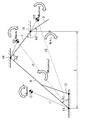
- FIG. 5 is a conceptual diagram illustrating a setting of post-excavation operation of the work machine 100 according to the first embodiment.
- the work machine 100 shows a case where the bucket 8 is moved to the soil removal position by the operation after excavation.
- the dump truck 200 is provided, and the work machine 100 discharges the earth and sand held by the bucket 8 on the loading platform of the dump truck 200.
- Point P10 is the excavation end point after the excavation operation, and is the turning start point (Start) at which the turning operation is started.
- the point P13 is a turning end point (Goal) at which the turning operation ends.
- the points P10 and P13 are three-dimensional coordinates and are stored in advance in the storage unit 32.
- the post-excavation operation setting unit 60 sets a first operation in which the boom 6 has a large vertical movement in the period after excavation and before soil removal, and a second operation in which the boom 6 has a small vertical movement.
- the post-excavation operation setting unit 60 raises the bucket 8 from the turning start point while turning the dump truck 200 so as not to interfere with the loading platform of the dump truck 200, and sets the height at the start of soil removal.
- the second operation of turning to the turning end point after setting the height at the start of excavation is set.
- Point P12 is a point where the first operation is switched to the second operation as a turning operation.
- the load measurement processing unit 52 executes a process of measuring the load inside the bucket 8 during the second operation period.
- the post-excavation motion setting unit 60 calculates the point P12 based on the point P10 and the point P13, and sets the section from the point P10 to the point P12 as the first operation and the point P12 to the point P13 as the second operation.
- the post-excavation motion setting unit 60 calculates the target bucket height HA for raising the bucket 8 based on the information at the points P10 and P13.
- the post-excavation operation setting unit 60 calculates a set period TB that raises the bucket 8 by the target bucket height HA based on the set speed in the vertical direction, which is the default value of the work machine 2.
- the storage unit 32 stores in advance a speed at which the boom 6 and the arm 7 are operated to raise or lower the bucket 8 as a set speed in the vertical direction, which is a default value of the work machine 2. Further, the turning speed is stored in advance in the storage unit 32.
- the post-excavation operation setting unit 60 calculates the point P12 based on the set period TB and the turning speed.
- the point P12 is calculated as a position where the target bucket height HA rises from the position of the point P10 and the turning angle ⁇ is swiveled based on the set period TB and the turning speed with reference to the central axis of the swivel body 3.
- the post-excavation operation setting unit 60 sets the height of the bucket 8 while controlling the swivel body 3 and the working machine 2 to perform the swivel operation for the set period TB until the bucket 8 reaches the point P10 to the point P12. Set to 1 operation.
- the post-excavation motion setting unit 60 sets the set period TA until the bucket 8 reaches the points P11 to P12 as the second motion in which only the swivel body 3 is controlled to execute the swivel motion.
- the load measurement processing unit 52 measures the load inside the bucket 8 during the period in which the second operation is executed.
- the period TA is a measurable period during which the load measurement processing unit 52 can measure the load inside the bucket 8.
- FIG. 6 is a diagram illustrating a bottom pressure of the boom cylinder 10 according to the first embodiment. As shown in FIG. 6, a case is shown in which an automatic control process for repeatedly executing a series of processes of excavation operation, post-excavation swivel operation, soil removal operation, and post-soil removal swivel operation is executed. A state in which the bottom pressure fluctuates based on the movement of the boom 6 during operation is shown.
- the first operation in which the boom 6 moves in the vertical direction is large and the second operation in which the boom 6 moves in the vertical direction is small are included.
- the bottom pressure is stable during the measurement period because the vertical movement of the boom 6 is small. Therefore, since the process of measuring the load inside the bucket 8 is executed during the second operation period when the bottom pressure is stable, highly accurate measurement process is possible.
- the state of the bottom pressure of the boom cylinder 10 is described, but the same applies to the state of the head pressure of the boom cylinder 10.
- the load measurement processing unit 52 can execute a process of measuring the load inside the bucket 8 when the bucket 8 reaches the point P12.
- the load measurement processing unit 52 executes a process of measuring the load inside the bucket 8 when the amount of change in the bottom pressure of the boom cylinder 10 detected by the pressure sensor 6b becomes equal to or less than a predetermined threshold value. May be good.
- the pressure sensor 6a may be used to execute a process of measuring the load inside the bucket 8 when the amount of change in the head pressure of the boom cylinder 10 is equal to or less than a predetermined threshold value. Good.
- the load measurement processing unit 52 has described the case of executing the process of measuring the load inside the bucket 8 when the point P12 is reached, the load measurement processing unit 52 is not limited to the predetermined position, and for example, the height of the bucket 8 is equal to or higher than the predetermined value. May be executed to measure the load inside the bucket 8 when the value is reached. Specifically, the load measurement processing unit 52 may execute a process of measuring the load inside the bucket 8 when the height of the bucket 8 rises by the target bucket height HA from the position of the point P10. ..
- the post-excavation operation setting unit 60 controls the work machine 2 and the swivel body 3 to raise the bucket 8 from the swivel start point in the period after excavation and before soil removal to start soil removal.
- the case where the first operation set to the height of the above is executed and only the swivel body 3 is controlled to execute the second operation has been described, but the present invention is not particularly limited to this.
- the post-excavation operation setting unit 60 controls only the swivel body 3 to execute the second operation in the period after excavation and before soil removal, and controls the work machine 2 and the swivel body 3 to discharge the bucket 8. It may be set to execute the first operation set near the height at the start of soil.
- the load measurement processing unit 52 executes a process of measuring the load inside the bucket 8 during the second operation in which the vertical movement of the boom 6 is small in the period after excavation and before soil removal. The case of doing so was explained.
- the measurable period TA is a predetermined period or longer in order to perform highly accurate measurement.
- FIG. 7 is a block diagram illustrating a functional configuration of the arithmetic unit 31 # of the work machine 100 based on the first modification of the first embodiment.
- the arithmetic unit 31 # is different from the arithmetic unit 31 described with reference to FIG. 4 in that the post-excavation operation setting unit 60 is replaced with the post-excavation operation setting unit 60 #. Since the other configurations are the same as those described in FIG. 4, the detailed description thereof will not be repeated.
- the post-excavation operation setting unit 60 # includes a turning target period calculation unit 64 and a setting unit 66.
- the turning target period calculation unit 64 calculates the first turning target period of the turning body 3 based on the turning start point and the turning end point of the turning body 3 and the turning speed of the turning body 3.
- the setting unit 66 determines whether or not the first turning target period is equal to or longer than a predetermined period. When the first turning target period is equal to or longer than the predetermined period, the setting unit 66 performs the first and second operations to measure the load inside the bucket 8 during at least the predetermined period. Set the operation. When the first turning target period is not equal to or longer than the predetermined period, the setting unit 66 performs the first and second operations so as to execute the second operation for the predetermined period or longer in order to measure the load inside the bucket 8. Set.
- the post-excavation operation setting unit 60 # calculates the first turning target period of the turning body 3 based on the turning start point and the turning end point of the turning body 3 and the turning speed of the turning body 3.
- the post-excavation motion setting unit 60 # determines whether or not the first turning target period is equal to or longer than a predetermined period. When the first turning target period is equal to or longer than the predetermined period, the post-excavation motion setting unit 60 # is so as to execute the second motion to measure the load inside the bucket 8 during at least the predetermined period. Set the 1st and 2nd operations.
- FIG. 8 is a conceptual diagram illustrating a setting of post-excavation operation of the work machine 100 according to the first modification of the first embodiment.
- the work machine 100 shows a case where the bucket 8 is moved to the soil removal position by the operation after excavation.
- the dump truck 200 is provided, and the work machine 100 discharges the earth and sand held by the bucket 8 on the loading platform of the dump truck 200.
- the post-excavation operation setting unit 60 # has a first operation of raising the bucket 8 from the turning start point and setting it to the height at the start of soil removal so as not to interfere with the loading platform of the dump truck 200, and soil discharge. After setting the height at the start, the second operation of turning to the turning end point is set.
- the turning target period calculation unit 64 calculates the turning angle ⁇ based on the central axes of the point P10, the point P13, and the turning body 3.
- the turning target period calculation unit 64 calculates the first turning target period T for turning the turning body 3 from the turning start point to the turning end point based on the turning angle ⁇ and the turning speed.
- the setting unit 66 determines whether or not the first turning target period T is equal to or longer than the predetermined period Tp. When the first turning target period T is equal to or longer than the predetermined period Tp, the setting unit 66 first executes the second operation to measure the load inside the bucket 8 during at least the predetermined period Tp or more. And set the second operation. When the first turning target period T is not equal to or longer than the predetermined period Tp, the setting unit 66 performs the first and first operations so as to execute the second operation for the predetermined period Tp or more in order to measure the load inside the bucket 8. 2 Set the operation.
- the setting unit 66 uses the remaining period Tq obtained by subtracting the predetermined period Tp from the first turning target period T to rotate the bucket 8 from the turning start point so as not to interfere with the loading platform of the dump truck 200. Set the first operation to raise and efficiently set the height at the start of soil removal.
- the setting unit 66 calculates the target bucket height HA for raising the bucket 8 based on the information of the points P10 and P13.
- the setting unit 66 calculates a set period TB for raising the bucket 8 by the target bucket height HA based on the set speed in the vertical direction, which is the default value of the work machine 2.
- the storage unit 32 stores in advance a speed at which the boom 6 and the arm 7 are operated to raise or lower the bucket 8 as a set speed in the vertical direction, which is a default value of the work machine 2.
- the setting unit 66 compares the period Tq and the set period TB, and describes the case where the period Tq is equal to or longer than the set period TB.
- the setting unit 66 sets the setting period TB of the period Tq to a period during which the first operation of setting the height of the bucket 8 is executed while controlling the swivel body 3 and the working machine 2 to perform the swivel operation.
- the setting unit 66 sets the period TA in which the set period TB is subtracted from the first turning target period T to the period in which only the turning body 3 is controlled to execute the second operation.
- the load measurement processing unit 52 measures the load inside the bucket 8 during the period in which the second operation is executed.
- the period TA is a measurable period during which the load measurement processing unit 52 can measure the load inside the bucket 8.
- the setting unit 66 sets the first and second operations so that the second operation of Tp for a predetermined period is always secured in the period after excavation and before soil removal.
- the predetermined period Tp is provided in the load measurement processing unit 52 to acquire a plurality of sampling points such as displacement amounts, head pressures, bottom pressures, etc. of the cylinders 10, 11 and 12 in order to measure a load with high accuracy. ing.
- the load measurement processing unit 52 can sufficiently acquire sampling points for measuring a load with high accuracy.
- the load measurement processing unit 52 executes a process of measuring the load inside the bucket 8 during the second operation in which the pressure of the hydraulic cylinder whose vertical movement of the boom 6 is small is stable, highly accurate measurement processing is possible. Is.
- the setting of the first and second operations of the setting unit 66 in the above is an example.
- the setting unit 66 controls only the swivel body 3 in the period after excavation and before soil removal so that the second operation of Tp for a predetermined period is secured from the turning start point, and turns using the period Tq. It is also possible to raise the bucket 8 while operating it and set it to execute the first operation of setting the height at the start of soil removal.
- the setting unit 66 may adjust the turning speed so that the second operation of the predetermined period Tp is secured as an example.
- the first turning target period T may be lengthened by slowing the turning speed to set the first and second movements in which the second movement of the predetermined period Tp or more is secured.
- FIG. 9 is a diagram illustrating a setting flow of the post-excavation operation by the post-excavation operation setting unit 60 # according to the first modification of the first embodiment.
- the post-excavation motion setting unit 60 # executes a process of calculating the turning target period (step S2).
- the turning target period calculation unit 64 calculates the turning angle ⁇ based on the turning start point P10, the turning end point P13, and the central axis of the turning body 3.
- the turning target period calculation unit 64 calculates the first turning target period T for turning the turning body 3 based on the turning angle ⁇ and the turning speed.
- the post-excavation operation setting unit 60 # determines whether or not the first turning target period is equal to or longer than a predetermined period (step S4).
- the setting unit 66 determines whether or not the first turning target period T is equal to or longer than the predetermined period Tp.
- the post-excavation operation setting unit 60 # determines that the first turning target period is equal to or longer than the predetermined period (YES in step S4)
- the first operation is executed so as to execute the second operation for the predetermined period or longer.
- the second operation is set (step S6).
- the process ends (end).
- the setting unit 66 sets the first and second operations so that the second operation of Tp for a predetermined period is surely secured in the period after excavation and before soil removal.
- step S4 when the post-excavation operation setting unit 60 # determines that the first turning target period is not equal to or longer than the predetermined period (NO in step S4), the turning speed is adjusted (step S8). Then, the process proceeds to step S6, and the post-excavation motion setting unit 60 sets the first and second motion turning motions so as to execute the second motion for a predetermined period or longer.
- the setting unit 66 adjusts and slows down the set turning speed of the turning body 3. Therefore, it is possible to lengthen the first turning target period T based on the adjusted turning speed. As described above, the setting unit 66 sets the first and second operations so that the second operation of Tp for a predetermined period is always secured in the period after excavation and before soil removal.
- the load measurement processing unit 52 can secure a measurable period of Tp or more for a predetermined period, and can sufficiently acquire sampling points for measuring the load. As a result, the load measurement processing unit 52 can perform highly accurate measurement processing.
- the load measurement processing unit 52 uses the start timing of soil removal as a trigger to acquire data for a predetermined period before soil removal, and executes a process of measuring the load inside the bucket 8. Is also good.
- Modification 2 In the first modification of the first embodiment, the case where the period Tq is equal to or longer than the set period TB has been described by comparing the period Tq and the set period TB in FIG. On the other hand, comparing the period Tq and the set period TB, it is possible that the period TB is longer than the period Tq. In this case, the measurable period TA may not be secured for a predetermined period Tp or more.
- the setting unit 66 compares the period Tq and the set period TB, and when the period TB is longer than the set period Tq, adjusts the set speed in the vertical direction, which is the default value of the work machine 2.
- the set period TB can be shortened by increasing the ascending speed of the boom 6 and the arm 7.
- the hydraulic oil distributed to the arm cylinder 11 may be accommodated in the boom cylinder 10 to accelerate the boom 6. By accelerating the boom 6, it is possible to increase the ascending speed and shorten the set period TB.
- the setting unit 66 adjusts the set speed in the vertical direction, which is the default value of the work machine 2, and shortens the set period TB for executing the first operation, thereby shortening the set period TB. It is possible to set the first and second operations so that the second operation of the above is always secured.
- the setting unit 66 may set the execution of the pre-turning preparatory process so that the second operation of Tp for a predetermined period is surely secured in the period after excavation and before soil removal.
- FIG. 10 is a block diagram illustrating a functional configuration of the arithmetic unit 31P of the work machine 100 based on the second modification of the first embodiment.
- the arithmetic unit 31P is different from the configuration of the arithmetic unit 31 # of FIG. 7 in that the post-excavation operation setting unit 60 # is replaced with the post-excavation operation setting unit 60P. Since the other configurations are the same, the detailed description thereof will not be repeated.
- the post-excavation operation setting unit 60P is different from the post-excavation operation setting unit 60 in that a pre-turning preparatory processing setting unit 69 is further provided.
- the post-excavation operation setting unit 60P determines that the measurable period TA cannot be secured for a predetermined period Tp or more, it sets the execution of the pre-turning preparatory process so that the measurable period TA becomes the predetermined period Tp or more.
- the pre-turning preparation processing setting unit 69 controls the work machine 2 before the start of the turning operation of the turning body 3 as a part of the first operation according to the instruction of the setting unit 66 to adjust the height of the bucket 8. Set the execution of the pre-turn preparatory process to be adjusted.
- FIG. 11 is a conceptual diagram illustrating a setting of post-excavation operation of the work machine 100 according to the second modification of the first embodiment.
- the work machine 100 shows a case where the bucket 8 is moved to the soil removal position by the operation after excavation as described in FIG. Then, the turning start point at which the turning operation is started is different.
- the point P10 is the excavation end point after the excavation operation.
- Point P11 is a turning start point at which the turning operation is started.
- Point P13 is a turning end point at which the turning operation ends.
- the pre-turning preparatory processing setting unit 69 sets the execution of the pre-turning preparatory processing that controls the work machine 2 from the point P10 to the point P11 to raise the height of the bucket 8.
- the post-excavation motion control unit 50 controls the work machine 2 before the start of the swivel operation of the swivel body 3 according to the setting of the pre-swivel preparatory process setting unit 69 to adjust the height of the bucket 8.
- the turning start point at which the turning operation is started by the pre-turning preparatory process is changed from P10 to P11.
- the target bucket height from the turning start point P11 is adjusted to HA #.
- the set period TB # that raises the bucket 8 to the height at the start of soil removal is shortened so that the second operation of the predetermined period Tp or more is always secured in the period after excavation and before soil removal. It is possible to set the execution of the pre-turn preparatory process to.
- the turning start point at which the turning operation is started is adjusted by setting the execution of the pre-turning preparation process so that the second operation of Tp or more for a predetermined period is always secured. Since the process of measuring the load inside the bucket 8 is executed during the second operation, highly accurate measurement process is possible. (Modification example 3) In the above, the case where the process of measuring the load inside the bucket 8 is executed in the period after excavation and before excavation has been described, but the load inside the bucket 8 is measured in the period after excavation and before excavation. The same can be applied when executing a process.
- FIG. 12 is a block diagram illustrating a functional configuration of the arithmetic unit 31Q of the work machine 100 based on the third modification of the first embodiment.
- the arithmetic unit 31Q is different from the configuration of the arithmetic unit 31 # described with reference to FIG. 7 in that it is further provided with a post-earth removal operation setting unit 70 for setting the operation after earth removal. .. Since the other configurations are the same as those described with reference to FIG. 7, the detailed description thereof will not be repeated.
- the operation setting unit 70 after excavation of soil controls the swivel operation by the swivel body 3 (swivel operation after excavation) and at least one of the working machines 2 to control the bucket 8 after excavation. Set the operation to move to the excavation position.
- the post-earthquake operation setting unit 70 sets a third operation in which the boom 6 has a large vertical movement in the period after excavation and before excavation, and a fourth operation in which the boom 6 has a small vertical movement.
- the post-earthquake operation control unit 58 executes the third operation and the fourth operation set by the post-excavation operation setting unit 70 in the period after excavation and before excavation.
- the soil removal operation control unit 58 moves the soil removal operation bucket 8 to the excavation position by controlling at least one of the rotation operation (soil removal operation) by the swivel body 3 and the work machine 2.
- the post-soil removal operation control unit 58 executes a third operation in which the boom 6 has a large vertical movement and a fourth operation in which the boom 6 has a small vertical movement.
- the excavation operation control unit 54 again controls the work machine 2 to execute an excavation operation for excavating earth and sand or the like, which is an object to be excavated, using the bucket 8. Subsequent operations are the same as above and are repeatedly executed.
- the post-soil removal operation control unit 58 and the post-soil removal operation setting unit 70 are examples of the “second operation control unit” and the “second operation setting unit” of the present disclosure.
- FIG. 13 is a conceptual diagram illustrating the setting of the operation after soil removal of the work machine 100 according to the third modification of the first embodiment.
- the work machine 100 shows a case where the bucket 8 is moved to the excavation position by the operation after excavation.
- a dump truck 200 is provided, and the work machine 100 moves the bucket 8 that has been excavated on the loading platform of the dump truck 200 to the excavation position.
- Point P13 # is the soil discharge end point after the soil discharge operation, and is the turning start point (Start) at which the turning operation is started.
- the point P10 # is a turning end point (Goal) at which the turning operation ends.
- the points P10 # and P13 # are three-dimensional coordinates and are stored in advance in the storage unit 32.
- the post-earthquake operation setting unit 70 sets a third operation in which the boom 6 has a large vertical movement in the period after excavation and before excavation, and a fourth operation in which the boom 6 has a small vertical movement.
- the post-soil removal operation setting unit 70 performs a fourth operation of turning the bucket 8 from the turning start point while maintaining the height at the end of soil removal so as not to interfere with the loading platform of the dump truck 200, and discharging.
- a third operation is set in which the height is lowered from the height at the end of soil and set to the height at the start of excavation.
- Point P12 # is a point where the fourth operation is switched to the third operation as a turning operation.
- the load measurement processing unit 52 executes a process of measuring the load inside the bucket 8 during the fourth operation period.
- the post-excretion operation setting unit 70 calculates the point P12 based on the points P10 # and the point P13 #, the section from the point P13 # to the point P12 # is the fourth operation, and the point P12 # to the point P10 # is the third. Set to operation.
- the post-earthquake operation setting unit 70 calculates the target bucket height HAP for lowering the bucket 8 based on the information of the points P10 # and the points P13 #.
- the operation setting unit 70 after excavation calculates the set period TTB for lowering the bucket 8 by the target bucket height HAP based on the set speed in the vertical direction, which is the default value of the work machine 2.
- the storage unit 32 stores in advance a speed at which the boom 6 and the arm 7 are operated to raise or lower the bucket 8 as a set speed in the vertical direction, which is a default value of the work machine 2. Further, the turning speed is stored in advance in the storage unit 32.
- the operation setting unit 70 after excavation calculates the point P12 # based on the set period TTB and the turning speed.
- the point P12 # swivels by a turning angle ⁇ minutes based on the set period TTB and the turning speed with reference to the central axis of the swivel body 3, and the target bucket is moved from the height of the point P13 #. It is calculated as the position when descending by the height HAP.
- the operation setting unit 70 after excavation sets the set period TTA until the bucket 8 reaches the points P13 # to the point P12 # as the fourth operation in which only the swivel body 3 is controlled to execute the swivel operation.
- the operation setting unit 70 after excavating the soil adjusts the height of the bucket 8 while controlling the swivel body 3 and the working machine 2 to perform the swivel operation for the set period TTB until the bucket 8 reaches the points P12 # to the point P10 #. Set to the third operation to be set.
- the load measurement processing unit 52 measures the load inside the bucket 8 during the period in which the fourth operation is executed.
- the period TTA is a measurable period during which the load measurement processing unit 52 can measure the load inside the bucket 8.
- FIG. 14 is a diagram illustrating the bottom pressure of the boom cylinder 10 according to the third modification of the first embodiment.
- FIG. 14 a case is shown in which an automatic control process for repeatedly executing a series of processes of excavation operation, post-excavation swivel operation, soil discharge operation, and post-soil excavation swivel operation is executed. A state in which the bottom pressure fluctuates based on the movement of the boom 6 during operation is shown.
- the first operation in which the boom 6 moves in the vertical direction is large and the second operation in which the boom 6 moves in the vertical direction is small are included.
- the bottom pressure is stable during the measurement period because the vertical movement of the boom 6 is small. Therefore, since the process of measuring the load inside the bucket 8 is executed during the period when the bottom pressure is stable, the measurement process with high accuracy is possible.
- the third operation in which the vertical movement of the boom 6 is large and the fourth operation in which the vertical movement of the boom 6 is small are included.
- the bottom pressure is stable during the measurement period because the vertical movement of the boom 6 is small. Therefore, since the process of measuring the load inside the bucket 8 is executed during the period when the bottom pressure is stable, the measurement process with high accuracy is possible.
- the state of the bottom pressure of the boom cylinder 10 is described, but the same applies to the state of the head pressure of the boom cylinder 10.
- FIG. 15 is a diagram illustrating a configuration of a hydraulic system of the work machine 100 according to the second embodiment.
- the work machine 100 includes a boom cylinder 10 for driving the boom 6, an arm cylinder 11 for driving the arm 7, a bucket cylinder 12 for driving the bucket 8, and a swivel motor for swiveling the swivel body 3. It includes 124, a controller 130 for controlling the work machine 100, an engine 138, a hydraulic pump 140, a main valve 125, a self-pressure reducing valve 146, and an EPC valve 150.
- the engine 138 is, for example, a diesel engine.
- the hydraulic pump 140 is driven by the engine 138 to discharge hydraulic oil.
- the hydraulic pump 140 is a variable displacement hydraulic pump. It may be a fixed-capacity hydraulic pump that changes the discharge amount of hydraulic oil according to the rotation speed of the engine 138.
- the main valve 125 receives the hydraulic oil supplied from the hydraulic pump 140, and distributes and supplies the hydraulic oil to the boom cylinder 10, the arm cylinder 11, the bucket cylinder 12, and the swivel motor 124, respectively.
- the controller 130 outputs a command current to the EPC valve 150.
- the EPC valve 150 controls the main valve 125 according to the command current from the controller 130.
- the hydraulic oil output from the hydraulic pump 140 is reduced to a constant pressure by the self-pressure pressure reducing valve 146 and supplied for the pilot.
- the controller 130 is composed of an arithmetic unit 131 (for example, a CPU (Central Processing Unit)), a storage unit 132, and the like, and controls the work machine 100 by executing a program or the like stored in the storage unit 132. ..
- an arithmetic unit 131 for example, a CPU (Central Processing Unit)
- a storage unit 132 for example, a hard disk drive, a solid state drive, or the like.
- the work machine 100 further includes an operation device 180 for operating the boom 6, a load measurement button 160, and a display 170.
- FIG. 16 is a block diagram illustrating a functional configuration of the arithmetic unit 131 of the work machine 100 based on the second embodiment.
- the arithmetic unit 131 of the work machine 100 based on the second embodiment has a load measurement processing unit 52 # that measures the load inside the bucket 8 and a boom restriction control unit 59 that limits the movement of the boom 6. And a display control unit 55 that controls the display content of the display 170.
- the load measurement processing unit 52 # measures the load inside the bucket 8 according to the operation instruction of the load measurement button 160. Since the measurement method is the same as that described in the first embodiment, the details thereof will not be repeated.
- the boom limiting control unit 59 limits the movement of the boom 6 according to the operation instruction of the load measurement button 160.
- the boom limit control unit 59 invalidates the input from the operation device 180 that operates the boom 6 according to the operation instruction of the load measurement button 160 for a predetermined period.
- the load measurement processing unit 52 # measures the load inside the bucket 8 during a predetermined period in which the movement of the boom 6 is restricted according to the operation instruction of the load measurement button 160.
- the case where the input from the operation device 180 that operates the boom 6 according to the operation instruction of the load measurement button 160 is invalidated for a predetermined period has been described, but the EPC valve is not invalid and is based on the operation command of the boom 6.
- the command current to 150 may be adjusted. Specifically, the movement of the boom 6 may be restricted by setting the upper limit value of the command current. Alternatively, the output of the command current to the EPC valve 150 based on the boom operation command may be delayed. Since the process of measuring the load inside the bucket 8 is executed during the period when the pressure of the boom cylinder 10 whose vertical movement of the boom 6 is restricted by the process is relatively stable, highly accurate measurement process is possible. is there.
- the method of limiting the movement of the boom 6 according to the operation instruction of the load measurement button 160 has been described, but the operator is urged to limit the movement of the boom 6 instead of forcibly limiting the movement of the boom 6.
- the guidance screen may be displayed.
- the display control unit 55 displays a guidance screen on the display 170 according to the operation instruction of the load measurement button 160.
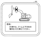
- FIG. 17 is a diagram illustrating a guidance screen during the measurement period according to the second embodiment.
- the guidance screen 300 displayed on the display 170 is shown with reference to FIG.
- the message "Please keep the movement in the vertical direction of the boom small during (warning) measurement" is displayed.
- the operator can prompt the operation of the boom 6 by the operating device 180.
- This process promotes the suppression of the vertical movement of the boom 6, and by executing the process of measuring the load inside the bucket 8 during the period when the pressure of the boom cylinder 10 is relatively stable, a highly accurate measurement process can be performed. It is possible.
- the above guidance screen may be displayed while forcibly restricting the movement of the boom 6.
- the display control unit 55 has described the case where the guidance screen is displayed on the display 170 according to the operation instruction of the load measurement button 160, but the guidance to the display 170 is based on the operation instruction of the boom 6 by the operation device 180.
- the screen may be displayed. For example, when the amount of operation of the boom 6 by the operating device 180 is equal to or greater than a predetermined amount, the guidance screen may be displayed assuming that the boom 6 has a large vertical movement.
- a speaker may be used to notify the warning sound.
- the message on the guidance screen 300 may be notified by using a speaker.
- a hydraulic excavator (backhoe) is mentioned as an example of a work machine, but it is not limited to the hydraulic excavator (backhoe), and other than a loading excavator, a mechanical rope excavator, an electric excavator, a wheel loader, a bucket crane and the like. It is also applicable to various types of work machines.
Landscapes
- Engineering & Computer Science (AREA)
- Mining & Mineral Resources (AREA)
- Civil Engineering (AREA)
- General Engineering & Computer Science (AREA)
- Structural Engineering (AREA)
- Mechanical Engineering (AREA)
- Physics & Mathematics (AREA)
- Fluid Mechanics (AREA)
- General Life Sciences & Earth Sciences (AREA)
- Paleontology (AREA)
- Life Sciences & Earth Sciences (AREA)
- General Physics & Mathematics (AREA)
- Operation Control Of Excavators (AREA)
- Component Parts Of Construction Machinery (AREA)
Abstract
La présente invention concerne un engin de chantier qui comprend : un appareil de travail comprenant un godet et une flèche ; un corps rotatif sur lequel l'appareil de travail est monté et qui effectue une opération de rotation ; une première unité de réglage de fonctionnement qui définit, pendant une durée après l'excavation mais avant l'élimination du sol, une première opération dans laquelle le mouvement de la flèche dans la direction verticale est grand, et une seconde opération dans laquelle le mouvement de la flèche dans la direction verticale est petit ; une première unité de commande de fonctionnement qui commande l'appareil de travail et/ou le corps rotatif pour exécuter la première opération et la seconde opération ; et une unité de traitement de mesure de charge qui mesure une charge à l'intérieur du godet durant la période de la seconde opération.
Priority Applications (4)
| Application Number | Priority Date | Filing Date | Title |
|---|---|---|---|
| CN202080082006.1A CN114787452A (zh) | 2019-12-02 | 2020-11-26 | 作业机械以及作业机械的控制方法 |
| DE112020004926.4T DE112020004926T5 (de) | 2019-12-02 | 2020-11-26 | Arbeitsmaschine und Steuerungsverfahren für die Arbeitsmaschine |
| KR1020227013572A KR102717651B1 (ko) | 2019-12-02 | 2020-11-26 | 작업 기계 및 작업 기계의 제어 방법 |
| US17/778,074 US20220412041A1 (en) | 2019-12-02 | 2020-11-26 | Work machine and control method for work machine |
Applications Claiming Priority (2)
| Application Number | Priority Date | Filing Date | Title |
|---|---|---|---|
| JP2019218013A JP7355624B2 (ja) | 2019-12-02 | 2019-12-02 | 作業機械および作業機械の制御方法 |
| JP2019-218013 | 2019-12-02 |
Publications (1)
| Publication Number | Publication Date |
|---|---|
| WO2021111963A1 true WO2021111963A1 (fr) | 2021-06-10 |
Family
ID=76219505
Family Applications (1)
| Application Number | Title | Priority Date | Filing Date |
|---|---|---|---|
| PCT/JP2020/043945 Ceased WO2021111963A1 (fr) | 2019-12-02 | 2020-11-26 | Engin de chantier et procédé de commande d'engin de chantier |
Country Status (6)
| Country | Link |
|---|---|
| US (1) | US20220412041A1 (fr) |
| JP (1) | JP7355624B2 (fr) |
| KR (1) | KR102717651B1 (fr) |
| CN (1) | CN114787452A (fr) |
| DE (1) | DE112020004926T5 (fr) |
| WO (1) | WO2021111963A1 (fr) |
Cited By (1)
| Publication number | Priority date | Publication date | Assignee | Title |
|---|---|---|---|---|
| DE102021210155A1 (de) | 2021-09-14 | 2023-03-16 | Robert Bosch Gesellschaft mit beschränkter Haftung | Verfahren zum Aufrufen einer Wiegefunktion einer Arbeitsmaschine und Arbeitsmaschine |
Families Citing this family (7)
| Publication number | Priority date | Publication date | Assignee | Title |
|---|---|---|---|---|
| GB2592237B (en) * | 2020-02-20 | 2022-07-20 | Terex Gb Ltd | Material processing apparatus with hybrid power system |
| JP7469127B2 (ja) * | 2020-04-17 | 2024-04-16 | 株式会社小松製作所 | 制御システムおよび制御方法 |
| JP7559691B2 (ja) * | 2021-07-09 | 2024-10-02 | コベルコ建機株式会社 | 作業機械 |
| US12123162B2 (en) * | 2021-09-29 | 2024-10-22 | Caterpillar Sarl | System, method, and apparatus for accurately determining payload transfer |
| JP7726762B2 (ja) * | 2021-12-06 | 2025-08-20 | 日立建機株式会社 | 作業機械 |
| JP7377391B1 (ja) | 2023-04-28 | 2023-11-09 | 株式会社Earthbrain | 推定装置、推定方法及びプログラム |
| JP2025016237A (ja) * | 2023-07-21 | 2025-01-31 | 株式会社小松製作所 | 積込機械の制御装置、積込機械の制御方法および遠隔操作システム |
Citations (5)
| Publication number | Priority date | Publication date | Assignee | Title |
|---|---|---|---|---|
| JPH04344427A (ja) * | 1991-03-05 | 1992-12-01 | Caterpillar Inc | ペイロード監視装置 |
| JP5406223B2 (ja) * | 2008-03-07 | 2014-02-05 | キャタピラー インコーポレイテッド | 適応型ペイロード監視システム |
| JP2016003462A (ja) * | 2014-06-16 | 2016-01-12 | 住友重機械工業株式会社 | ショベル支援装置 |
| JP2018145754A (ja) * | 2017-03-09 | 2018-09-20 | 日立建機株式会社 | 作業機械の荷重計測装置 |
| JP2018188831A (ja) * | 2017-04-28 | 2018-11-29 | 株式会社小松製作所 | 作業機械および作業機械の制御方法 |
Family Cites Families (9)
| Publication number | Priority date | Publication date | Assignee | Title |
|---|---|---|---|---|
| US5261026A (en) * | 1990-05-22 | 1993-11-09 | Kabushiki Kaisha Komatsu Seisakusho | Controlling apparatus for balanced cargo or work handling system |
| JP2002332663A (ja) * | 2001-05-09 | 2002-11-22 | Hitachi Constr Mach Co Ltd | 油圧ショベルの荷重計測装置 |
| US6931772B2 (en) * | 2001-10-18 | 2005-08-23 | Hitachi Construction Machinery Co., Ltd. | Hydraulic shovel work amount detection apparatus, work amount detection method, work amount detection result display apparatus |
| JP6415839B2 (ja) * | 2014-03-31 | 2018-10-31 | 住友重機械工業株式会社 | ショベル |
| CN113107045A (zh) * | 2015-12-28 | 2021-07-13 | 住友建机株式会社 | 挖土机以及挖土机用的控制装置和挖土机的控制方法 |
| CN118929540A (zh) * | 2016-07-29 | 2024-11-12 | I.M.A.工业机械自动装置股份公司 | 容器填充和秤重的方法及相关填充和秤重的单元 |
| DE102016011530A1 (de) | 2016-09-23 | 2018-03-29 | Liebherr-Mining Equipment Colmar Sas | Verfahren zum Assistieren eines Baggerführers beim Beladen eines Transportgerätes sowie Assistenzsystem |
| US11125605B2 (en) * | 2017-03-03 | 2021-09-21 | Cnh Industrial America Llc | System and method for estimating implement load weights for a work vehicle |
| WO2019151335A1 (fr) * | 2018-01-30 | 2019-08-08 | 住友建機株式会社 | Pelle et système de gestion de pelle |
-
2019
- 2019-12-02 JP JP2019218013A patent/JP7355624B2/ja active Active
-
2020
- 2020-11-26 KR KR1020227013572A patent/KR102717651B1/ko active Active
- 2020-11-26 US US17/778,074 patent/US20220412041A1/en not_active Abandoned
- 2020-11-26 DE DE112020004926.4T patent/DE112020004926T5/de active Pending
- 2020-11-26 CN CN202080082006.1A patent/CN114787452A/zh active Pending
- 2020-11-26 WO PCT/JP2020/043945 patent/WO2021111963A1/fr not_active Ceased
Patent Citations (5)
| Publication number | Priority date | Publication date | Assignee | Title |
|---|---|---|---|---|
| JPH04344427A (ja) * | 1991-03-05 | 1992-12-01 | Caterpillar Inc | ペイロード監視装置 |
| JP5406223B2 (ja) * | 2008-03-07 | 2014-02-05 | キャタピラー インコーポレイテッド | 適応型ペイロード監視システム |
| JP2016003462A (ja) * | 2014-06-16 | 2016-01-12 | 住友重機械工業株式会社 | ショベル支援装置 |
| JP2018145754A (ja) * | 2017-03-09 | 2018-09-20 | 日立建機株式会社 | 作業機械の荷重計測装置 |
| JP2018188831A (ja) * | 2017-04-28 | 2018-11-29 | 株式会社小松製作所 | 作業機械および作業機械の制御方法 |
Cited By (1)
| Publication number | Priority date | Publication date | Assignee | Title |
|---|---|---|---|---|
| DE102021210155A1 (de) | 2021-09-14 | 2023-03-16 | Robert Bosch Gesellschaft mit beschränkter Haftung | Verfahren zum Aufrufen einer Wiegefunktion einer Arbeitsmaschine und Arbeitsmaschine |
Also Published As
| Publication number | Publication date |
|---|---|
| KR20220066157A (ko) | 2022-05-23 |
| CN114787452A (zh) | 2022-07-22 |
| JP7355624B2 (ja) | 2023-10-03 |
| DE112020004926T5 (de) | 2022-06-23 |
| JP2021088815A (ja) | 2021-06-10 |
| KR102717651B1 (ko) | 2024-10-15 |
| US20220412041A1 (en) | 2022-12-29 |
Similar Documents
| Publication | Publication Date | Title |
|---|---|---|
| WO2021111963A1 (fr) | Engin de chantier et procédé de commande d'engin de chantier | |
| US11085168B2 (en) | Work machine | |
| US20200208373A1 (en) | Work Machine | |
| KR102430343B1 (ko) | 건설 기계 | |
| JP6986853B2 (ja) | 作業機械および作業機械の制御方法 | |
| EP3907336A1 (fr) | Dispositif de surveillance et engin de chantier | |
| CN115176057B (zh) | 工程机械 | |
| JP7253949B2 (ja) | 作業機械、システムおよび作業機械の制御方法 | |
| JP2021050492A (ja) | 油圧ショベル | |
| JP2021011694A (ja) | 作業機械および作業機械の制御方法 | |
| JP7353958B2 (ja) | 作業機械、計測方法およびシステム | |
| US12523002B2 (en) | Work machine | |
| JP2013124461A (ja) | 油圧ショベルの荷重計測装置 | |
| US12163825B2 (en) | Work machine | |
| JP2022157266A (ja) | 演算装置および演算方法 | |
| WO2020255622A1 (fr) | Engin de chantier et procédé de commande pour engins de chantier | |
| JP2025074594A (ja) | 作業機械および作業機械の制御方法 | |
| JP2024057328A (ja) | 作業機械の異常判定装置及びこれを備えた作業機械 | |
| JP7562429B2 (ja) | 建設機械 | |
| JP7268577B2 (ja) | 作業機械 | |
| CN121729541A (zh) | 作业机械 | |
| JP2024154697A (ja) | 作業機械および積荷質量算出方法 | |
| JP2025166671A (ja) | 作業機械のペイロード算出システムおよび作業機械のペイロード算出方法 |
Legal Events
| Date | Code | Title | Description |
|---|---|---|---|
| 121 | Ep: the epo has been informed by wipo that ep was designated in this application |
Ref document number: 20895817 Country of ref document: EP Kind code of ref document: A1 |
|
| ENP | Entry into the national phase |
Ref document number: 20227013572 Country of ref document: KR Kind code of ref document: A |
|
| 122 | Ep: pct application non-entry in european phase |
Ref document number: 20895817 Country of ref document: EP Kind code of ref document: A1 |