WO2021131184A1 - 電池制御装置及び電池システム - Google Patents
電池制御装置及び電池システム Download PDFInfo
- Publication number
- WO2021131184A1 WO2021131184A1 PCT/JP2020/035632 JP2020035632W WO2021131184A1 WO 2021131184 A1 WO2021131184 A1 WO 2021131184A1 JP 2020035632 W JP2020035632 W JP 2020035632W WO 2021131184 A1 WO2021131184 A1 WO 2021131184A1
- Authority
- WO
- WIPO (PCT)
- Prior art keywords
- battery
- internal resistance
- value
- control device
- unit
- Prior art date
- Legal status (The legal status is an assumption and is not a legal conclusion. Google has not performed a legal analysis and makes no representation as to the accuracy of the status listed.)
- Ceased
Links
Images


Classifications
-
- H—ELECTRICITY
- H02—GENERATION; CONVERSION OR DISTRIBUTION OF ELECTRIC POWER
- H02J—ELECTRIC POWER NETWORKS; CIRCUIT ARRANGEMENTS OR SYSTEMS FOR SUPPLYING OR DISTRIBUTING ELECTRIC POWER; SYSTEMS FOR STORING ELECTRIC ENERGY
- H02J7/00—Circuit arrangements for charging or discharging batteries or for supplying loads from batteries
- H02J7/80—Circuit arrangements for charging or discharging batteries or for supplying loads from batteries including monitoring or indicating arrangements
- H02J7/84—Control of state of health [SOH]
-
- H—ELECTRICITY
- H01—ELECTRIC ELEMENTS
- H01M—PROCESSES OR MEANS, e.g. BATTERIES, FOR THE DIRECT CONVERSION OF CHEMICAL ENERGY INTO ELECTRICAL ENERGY
- H01M10/00—Secondary cells; Manufacture thereof
- H01M10/42—Methods or arrangements for servicing or maintenance of secondary cells or secondary half-cells
- H01M10/425—Structural combination with electronic components, e.g. electronic circuits integrated to the outside of the casing
- H01M10/4257—Smart batteries, e.g. electronic circuits inside the housing of the cells or batteries
-
- G—PHYSICS
- G01—MEASURING; TESTING
- G01R—MEASURING ELECTRIC VARIABLES; MEASURING MAGNETIC VARIABLES
- G01R31/00—Arrangements for testing electric properties; Arrangements for locating electric faults; Arrangements for electrical testing characterised by what is being tested not provided for elsewhere
- G01R31/36—Arrangements for testing, measuring or monitoring the electrical condition of accumulators or electric batteries, e.g. capacity or state of charge [SoC]
- G01R31/367—Software therefor, e.g. for battery testing using modelling or look-up tables
-
- G—PHYSICS
- G01—MEASURING; TESTING
- G01R—MEASURING ELECTRIC VARIABLES; MEASURING MAGNETIC VARIABLES
- G01R31/00—Arrangements for testing electric properties; Arrangements for locating electric faults; Arrangements for electrical testing characterised by what is being tested not provided for elsewhere
- G01R31/36—Arrangements for testing, measuring or monitoring the electrical condition of accumulators or electric batteries, e.g. capacity or state of charge [SoC]
- G01R31/374—Arrangements for testing, measuring or monitoring the electrical condition of accumulators or electric batteries, e.g. capacity or state of charge [SoC] with means for correcting the measurement for temperature or ageing
-
- G—PHYSICS
- G01—MEASURING; TESTING
- G01R—MEASURING ELECTRIC VARIABLES; MEASURING MAGNETIC VARIABLES
- G01R31/00—Arrangements for testing electric properties; Arrangements for locating electric faults; Arrangements for electrical testing characterised by what is being tested not provided for elsewhere
- G01R31/36—Arrangements for testing, measuring or monitoring the electrical condition of accumulators or electric batteries, e.g. capacity or state of charge [SoC]
- G01R31/382—Arrangements for monitoring battery or accumulator variables, e.g. SoC
- G01R31/3842—Arrangements for monitoring battery or accumulator variables, e.g. SoC combining voltage and current measurements
-
- G—PHYSICS
- G01—MEASURING; TESTING
- G01R—MEASURING ELECTRIC VARIABLES; MEASURING MAGNETIC VARIABLES
- G01R31/00—Arrangements for testing electric properties; Arrangements for locating electric faults; Arrangements for electrical testing characterised by what is being tested not provided for elsewhere
- G01R31/36—Arrangements for testing, measuring or monitoring the electrical condition of accumulators or electric batteries, e.g. capacity or state of charge [SoC]
- G01R31/389—Measuring internal impedance, internal conductance or related variables
-
- G—PHYSICS
- G01—MEASURING; TESTING
- G01R—MEASURING ELECTRIC VARIABLES; MEASURING MAGNETIC VARIABLES
- G01R31/00—Arrangements for testing electric properties; Arrangements for locating electric faults; Arrangements for electrical testing characterised by what is being tested not provided for elsewhere
- G01R31/36—Arrangements for testing, measuring or monitoring the electrical condition of accumulators or electric batteries, e.g. capacity or state of charge [SoC]
- G01R31/392—Determining battery ageing or deterioration, e.g. state of health
-
- H—ELECTRICITY
- H01—ELECTRIC ELEMENTS
- H01M—PROCESSES OR MEANS, e.g. BATTERIES, FOR THE DIRECT CONVERSION OF CHEMICAL ENERGY INTO ELECTRICAL ENERGY
- H01M10/00—Secondary cells; Manufacture thereof
- H01M10/42—Methods or arrangements for servicing or maintenance of secondary cells or secondary half-cells
- H01M10/425—Structural combination with electronic components, e.g. electronic circuits integrated to the outside of the casing
-
- H—ELECTRICITY
- H01—ELECTRIC ELEMENTS
- H01M—PROCESSES OR MEANS, e.g. BATTERIES, FOR THE DIRECT CONVERSION OF CHEMICAL ENERGY INTO ELECTRICAL ENERGY
- H01M10/00—Secondary cells; Manufacture thereof
- H01M10/42—Methods or arrangements for servicing or maintenance of secondary cells or secondary half-cells
- H01M10/48—Accumulators combined with arrangements for measuring, testing or indicating the condition of cells, e.g. the level or density of the electrolyte
- H01M10/482—Accumulators combined with arrangements for measuring, testing or indicating the condition of cells, e.g. the level or density of the electrolyte for several batteries or cells simultaneously or sequentially
-
- H—ELECTRICITY
- H01—ELECTRIC ELEMENTS
- H01M—PROCESSES OR MEANS, e.g. BATTERIES, FOR THE DIRECT CONVERSION OF CHEMICAL ENERGY INTO ELECTRICAL ENERGY
- H01M10/00—Secondary cells; Manufacture thereof
- H01M10/42—Methods or arrangements for servicing or maintenance of secondary cells or secondary half-cells
- H01M10/48—Accumulators combined with arrangements for measuring, testing or indicating the condition of cells, e.g. the level or density of the electrolyte
- H01M10/486—Accumulators combined with arrangements for measuring, testing or indicating the condition of cells, e.g. the level or density of the electrolyte for measuring temperature
-
- H—ELECTRICITY
- H01—ELECTRIC ELEMENTS
- H01M—PROCESSES OR MEANS, e.g. BATTERIES, FOR THE DIRECT CONVERSION OF CHEMICAL ENERGY INTO ELECTRICAL ENERGY
- H01M50/00—Constructional details or processes of manufacture of the non-active parts of electrochemical cells other than fuel cells, e.g. hybrid cells
- H01M50/20—Mountings; Secondary casings or frames; Racks, modules or packs; Suspension devices; Shock absorbers; Transport or carrying devices; Holders
- H01M50/204—Racks, modules or packs for multiple batteries or multiple cells
-
- H—ELECTRICITY
- H01—ELECTRIC ELEMENTS
- H01M—PROCESSES OR MEANS, e.g. BATTERIES, FOR THE DIRECT CONVERSION OF CHEMICAL ENERGY INTO ELECTRICAL ENERGY
- H01M50/00—Constructional details or processes of manufacture of the non-active parts of electrochemical cells other than fuel cells, e.g. hybrid cells
- H01M50/20—Mountings; Secondary casings or frames; Racks, modules or packs; Suspension devices; Shock absorbers; Transport or carrying devices; Holders
- H01M50/249—Mountings; Secondary casings or frames; Racks, modules or packs; Suspension devices; Shock absorbers; Transport or carrying devices; Holders specially adapted for aircraft or vehicles, e.g. cars or trains
-
- H—ELECTRICITY
- H02—GENERATION; CONVERSION OR DISTRIBUTION OF ELECTRIC POWER
- H02J—ELECTRIC POWER NETWORKS; CIRCUIT ARRANGEMENTS OR SYSTEMS FOR SUPPLYING OR DISTRIBUTING ELECTRIC POWER; SYSTEMS FOR STORING ELECTRIC ENERGY
- H02J7/00—Circuit arrangements for charging or discharging batteries or for supplying loads from batteries
- H02J7/90—Regulation of charging or discharging current or voltage
- H02J7/927—Regulation of charging or discharging current or voltage with introduction of pulses during the charging process
-
- B—PERFORMING OPERATIONS; TRANSPORTING
- B60—VEHICLES IN GENERAL
- B60L—PROPULSION OF ELECTRICALLY-PROPELLED VEHICLES; SUPPLYING ELECTRIC POWER FOR AUXILIARY EQUIPMENT OF ELECTRICALLY-PROPELLED VEHICLES; ELECTRODYNAMIC BRAKE SYSTEMS FOR VEHICLES IN GENERAL; MAGNETIC SUSPENSION OR LEVITATION FOR VEHICLES; MONITORING OPERATING VARIABLES OF ELECTRICALLY-PROPELLED VEHICLES; ELECTRIC SAFETY DEVICES FOR ELECTRICALLY-PROPELLED VEHICLES
- B60L50/00—Electric propulsion with power supplied within the vehicle
- B60L50/50—Electric propulsion with power supplied within the vehicle using propulsion power supplied by batteries or fuel cells
- B60L50/60—Electric propulsion with power supplied within the vehicle using propulsion power supplied by batteries or fuel cells using power supplied by batteries
-
- B—PERFORMING OPERATIONS; TRANSPORTING
- B60—VEHICLES IN GENERAL
- B60L—PROPULSION OF ELECTRICALLY-PROPELLED VEHICLES; SUPPLYING ELECTRIC POWER FOR AUXILIARY EQUIPMENT OF ELECTRICALLY-PROPELLED VEHICLES; ELECTRODYNAMIC BRAKE SYSTEMS FOR VEHICLES IN GENERAL; MAGNETIC SUSPENSION OR LEVITATION FOR VEHICLES; MONITORING OPERATING VARIABLES OF ELECTRICALLY-PROPELLED VEHICLES; ELECTRIC SAFETY DEVICES FOR ELECTRICALLY-PROPELLED VEHICLES
- B60L58/00—Methods or circuit arrangements for monitoring or controlling batteries or fuel cells, specially adapted for electric vehicles
- B60L58/10—Methods or circuit arrangements for monitoring or controlling batteries or fuel cells, specially adapted for electric vehicles for monitoring or controlling batteries
- B60L58/12—Methods or circuit arrangements for monitoring or controlling batteries or fuel cells, specially adapted for electric vehicles for monitoring or controlling batteries responding to state of charge [SoC]
-
- B—PERFORMING OPERATIONS; TRANSPORTING
- B60—VEHICLES IN GENERAL
- B60L—PROPULSION OF ELECTRICALLY-PROPELLED VEHICLES; SUPPLYING ELECTRIC POWER FOR AUXILIARY EQUIPMENT OF ELECTRICALLY-PROPELLED VEHICLES; ELECTRODYNAMIC BRAKE SYSTEMS FOR VEHICLES IN GENERAL; MAGNETIC SUSPENSION OR LEVITATION FOR VEHICLES; MONITORING OPERATING VARIABLES OF ELECTRICALLY-PROPELLED VEHICLES; ELECTRIC SAFETY DEVICES FOR ELECTRICALLY-PROPELLED VEHICLES
- B60L58/00—Methods or circuit arrangements for monitoring or controlling batteries or fuel cells, specially adapted for electric vehicles
- B60L58/10—Methods or circuit arrangements for monitoring or controlling batteries or fuel cells, specially adapted for electric vehicles for monitoring or controlling batteries
- B60L58/18—Methods or circuit arrangements for monitoring or controlling batteries or fuel cells, specially adapted for electric vehicles for monitoring or controlling batteries of two or more battery modules
-
- G—PHYSICS
- G01—MEASURING; TESTING
- G01R—MEASURING ELECTRIC VARIABLES; MEASURING MAGNETIC VARIABLES
- G01R31/00—Arrangements for testing electric properties; Arrangements for locating electric faults; Arrangements for electrical testing characterised by what is being tested not provided for elsewhere
- G01R31/36—Arrangements for testing, measuring or monitoring the electrical condition of accumulators or electric batteries, e.g. capacity or state of charge [SoC]
- G01R31/382—Arrangements for monitoring battery or accumulator variables, e.g. SoC
- G01R31/3828—Arrangements for monitoring battery or accumulator variables, e.g. SoC using current integration
-
- G—PHYSICS
- G01—MEASURING; TESTING
- G01R—MEASURING ELECTRIC VARIABLES; MEASURING MAGNETIC VARIABLES
- G01R31/00—Arrangements for testing electric properties; Arrangements for locating electric faults; Arrangements for electrical testing characterised by what is being tested not provided for elsewhere
- G01R31/36—Arrangements for testing, measuring or monitoring the electrical condition of accumulators or electric batteries, e.g. capacity or state of charge [SoC]
- G01R31/396—Acquisition or processing of data for testing or for monitoring individual cells or groups of cells within a battery
-
- H—ELECTRICITY
- H01—ELECTRIC ELEMENTS
- H01M—PROCESSES OR MEANS, e.g. BATTERIES, FOR THE DIRECT CONVERSION OF CHEMICAL ENERGY INTO ELECTRICAL ENERGY
- H01M10/00—Secondary cells; Manufacture thereof
- H01M10/42—Methods or arrangements for servicing or maintenance of secondary cells or secondary half-cells
- H01M10/425—Structural combination with electronic components, e.g. electronic circuits integrated to the outside of the casing
- H01M2010/4271—Battery management systems including electronic circuits, e.g. control of current or voltage to keep battery in healthy state, cell balancing
-
- H—ELECTRICITY
- H01—ELECTRIC ELEMENTS
- H01M—PROCESSES OR MEANS, e.g. BATTERIES, FOR THE DIRECT CONVERSION OF CHEMICAL ENERGY INTO ELECTRICAL ENERGY
- H01M2220/00—Batteries for particular applications
- H01M2220/20—Batteries in motive systems, e.g. vehicle, ship, plane
-
- H—ELECTRICITY
- H02—GENERATION; CONVERSION OR DISTRIBUTION OF ELECTRIC POWER
- H02J—ELECTRIC POWER NETWORKS; CIRCUIT ARRANGEMENTS OR SYSTEMS FOR SUPPLYING OR DISTRIBUTING ELECTRIC POWER; SYSTEMS FOR STORING ELECTRIC ENERGY
- H02J7/00—Circuit arrangements for charging or discharging batteries or for supplying loads from batteries
- H02J7/90—Regulation of charging or discharging current or voltage
- H02J7/971—Regulation of charging or discharging current or voltage the charge cycle being controlled or terminated in response to non-electric parameters
- H02J7/975—Regulation of charging or discharging current or voltage the charge cycle being controlled or terminated in response to non-electric parameters in response to temperature
- H02J7/977—Regulation of charging or discharging current or voltage the charge cycle being controlled or terminated in response to non-electric parameters in response to temperature of the battery
-
- Y—GENERAL TAGGING OF NEW TECHNOLOGICAL DEVELOPMENTS; GENERAL TAGGING OF CROSS-SECTIONAL TECHNOLOGIES SPANNING OVER SEVERAL SECTIONS OF THE IPC; TECHNICAL SUBJECTS COVERED BY FORMER USPC CROSS-REFERENCE ART COLLECTIONS [XRACs] AND DIGESTS
- Y02—TECHNOLOGIES OR APPLICATIONS FOR MITIGATION OR ADAPTATION AGAINST CLIMATE CHANGE
- Y02E—REDUCTION OF GREENHOUSE GAS [GHG] EMISSIONS, RELATED TO ENERGY GENERATION, TRANSMISSION OR DISTRIBUTION
- Y02E60/00—Enabling technologies; Technologies with a potential or indirect contribution to GHG emissions mitigation
- Y02E60/10—Energy storage using batteries
-
- Y—GENERAL TAGGING OF NEW TECHNOLOGICAL DEVELOPMENTS; GENERAL TAGGING OF CROSS-SECTIONAL TECHNOLOGIES SPANNING OVER SEVERAL SECTIONS OF THE IPC; TECHNICAL SUBJECTS COVERED BY FORMER USPC CROSS-REFERENCE ART COLLECTIONS [XRACs] AND DIGESTS
- Y02—TECHNOLOGIES OR APPLICATIONS FOR MITIGATION OR ADAPTATION AGAINST CLIMATE CHANGE
- Y02T—CLIMATE CHANGE MITIGATION TECHNOLOGIES RELATED TO TRANSPORTATION
- Y02T10/00—Road transport of goods or passengers
- Y02T10/60—Other road transportation technologies with climate change mitigation effect
- Y02T10/70—Energy storage systems for electromobility, e.g. batteries
Definitions
- the present invention relates to a battery control device and a battery system.
- Electric vehicle systems installed in electric vehicles such as electric vehicles (EV: Electric Vehicle), plug-in hybrid vehicles (PHEV: Plug-in Hybrid Electric Vehicle), and hybrid vehicles (HEV: Hybrid Electric Vehicle) are used as power supply sources. It has a battery and a battery control device.
- the battery control device detects the voltage, temperature, and current of the battery in order to maximize the performance of the battery, and based on these, the charged state (SOC: State of Charge) and the deteriorated state (SOH: State) of the battery. ofHealth), calculates the power that can be input and output from the battery.
- the internal resistance of the battery increases as it deteriorates. Therefore, the internal resistance value of the battery is calculated in real time and used to properly calculate the input / output power of the battery, and the ratio between the initial internal resistance value and the deteriorated internal resistance value is calculated as SOH. It is used as a guide for battery replacement.
- the method of calculating the internal resistance of the battery is based on the method of calculating based on the internal resistance of the battery calculated from the ratio of the amount of change in battery voltage and the amount of change in current, and the method of calculating based on the internal resistance calculated by the equivalent circuit model of the battery. There is a method of calculation.
- Patent Document 1 describes the SOC difference between SOC (hereinafter, SOCv) calculated based on the internal resistance calculated by the internal resistance calculation method based on the latter equivalent circuit model and SOC (hereinafter, SOCi) based on current integration. Is detected as a change in internal resistance due to battery deterioration, and a technique for correcting the internal resistance used in SOH calculation is disclosed.
- the correction value of the internal resistance determined to be necessary to be corrected due to the occurrence of SOC difference is set as a relatively small fixed value, and the stability of calculation is emphasized. Therefore, even if the calculated value of SOH recognized by the battery control device and the actual SOH (also called the true value of SOH) of the battery to be controlled are significantly different, the internal resistance is corrected with a small fixed value. Therefore, there is a problem that the convergence speed at which the SOH calculated value converges to the true SOH value is slow.
- An object of the present invention is to provide a battery control device and a battery system capable of increasing the convergence speed of the SOH calculated value and estimating the internal resistance value with high accuracy in order to solve the above-mentioned problems. To do.
- the battery control device calculates the first charge state of the battery by the first method based on the current value, the voltage value, and the internal resistance value of the battery.
- the calculation unit includes a calculation unit, a second calculation unit that calculates the second charge state of the battery by a second method different from the first method, and a correction unit that corrects the internal resistance value of the battery.
- the correction unit uses a resistance correction amount corresponding to the difference and the current value inside the battery. The resistance value is corrected.
- the reliability of the battery system can be ensured and the battery can be used efficiently.
- FIG. 3 is a block diagram showing a configuration of an assembled battery control unit constituting the battery system of FIG. 1.
- FIG. The block diagram which shows the structure of the SOH calculation part in Example 1.
- FIG. The figure which shows the internal resistance correction amount map in Example 1.
- FIG. The flowchart which shows the SOH calculation process in Example 1.
- FIG. The block diagram which shows the structure of the SOH calculation part in Example 2.
- FIG. The figure which shows the internal resistance correction amount map in Example 2.
- FIG. The figure which shows the profile of the SOH calculation at the time of the charge / discharge pulse input in the high temperature region in Example 1.
- FIG. The figure which shows the resistance correction amount map in the modification of Example 2.
- a case where the application is applied to a power storage device constituting a power source of a hybrid electric vehicle (HEV) will be described as an example.
- the present invention is not limited to this, and the configuration of the embodiment described below is a power storage device for a power storage device that constitutes a power source for a passenger vehicle such as a plug-in hybrid vehicle (PHEV) or an electric vehicle (EV) or an industrial vehicle such as a hybrid railroad vehicle. It can also be applied to control circuits.
- PHEV plug-in hybrid vehicle
- EV electric vehicle
- industrial vehicle such as a hybrid railroad vehicle.
- a lithium ion battery is applied to the capacitor constituting the power storage unit.
- a nickel hydrogen battery, a lead battery, an electric double layer capacitor, a hybrid capacitor and the like can also be used as the power storage device.
- Example 1 of the present invention will be described with reference to FIGS. 1 to 14.
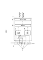
- FIG. 1 is a block diagram showing a configuration of an electric system S of a hybrid vehicle according to a first embodiment of the present invention.
- the battery system 100 is connected to the inverter 400 and the motor 410 via the relays 300 and 310.
- the vehicle control unit 200 determines the distribution of the driving force and the like based on the information including the SOC of the battery system 100, the information from the inverter 400 and the motor 410, and the information of the engine (not shown).
- the configuration of the battery system 100 will be described.
- the battery system 100 includes an assembled battery 110 composed of a plurality of cells 111, a cell management unit 120 for monitoring the state of the cell 111, and a current detecting unit 130 for detecting the current flowing through the battery system 100.
- a memory that stores information on the battery characteristics of the voltage detection unit 140 that detects the total voltage of the battery 110, the battery control unit 150 that controls the battery 110, the cell 111, the cell group 112, and the battery 110. It is configured to include a part 180 and the like.
- the assembled battery control unit 150 is a set that transmits the battery voltage and temperature of the cell 111 transmitted from the cell management unit 120, the current value flowing through the battery system 100 transmitted from the current detection unit 130, and the voltage detection unit 140.
- the total voltage value of the battery 110, the diagnosis result of whether the cell 111 is overcharged or overdischarged, and the abnormal signal output when a communication error occurs in the cell management unit 120 are input and input.
- the state of the assembled battery 110 is detected based on the information. Further, the result of the process performed by the assembled battery control unit 150 is transmitted to the unit battery management unit 120 and the vehicle control unit 200.
- the assembled battery 110 is configured by electrically connecting a plurality of single batteries 111 (lithium ion batteries) capable of storing and discharging electric energy (charging / discharging DC power) in series.
- a plurality of single batteries 111 lithium ion batteries
- One cell 111 has an output voltage of 3.0 to 4.2 V (average output voltage: 3.6 V), and the OCV and SOC of the cell 111 have a correlation as shown in FIG. The case will be described as an example, but other voltage specifications may be used.
- the unit batteries 111 constituting the assembled battery 110 are grouped into a predetermined number of units in order to manage and control the state.
- the grouped cell cells 111 are electrically connected in series to form a cell group 112.
- the predetermined number of units may be divided into equal categories, for example, 1, 4, 6, ..., Or may be combined into a compound category, such as combining 4 and 6. is there.
- the cell management unit 120 that monitors the state of the cell 111 that constitutes the assembled battery 110 is composed of a plurality of cell control units 121, and is 1 for the cell group 112 grouped as described above. Two cell control units 121 are assigned. The cell control unit 121 operates by receiving electric power from the assigned cell group 112, and monitors the battery voltage and temperature of the cell 111 constituting the cell group 112. In FIG. 1, the cell cell control units 121a and 121b are provided corresponding to the cell cell groups 112a and 112b. In this embodiment, for the sake of simplicity, it is assumed that the cell group 112 has a configuration in which four cell cells 111 are electrically connected in series, and four cell cells 111 are connected to one. It is configured to be monitored by one cell control unit 121.
- FIG. 2 is a block diagram showing a configuration of a cell control unit 121 constituting the battery system 100 of FIG. 1.
- the cell control unit 121 includes a voltage detection circuit 122, a control circuit 123, a signal input / output circuit 124, and a temperature detection unit 125.
- the voltage detection circuit 122 measures the voltage between terminals of each cell 111.
- the temperature detection unit 125 measures the temperature of the cell group 112.
- the control circuit 123 receives the measurement results from the voltage detection circuit 122 and the temperature detection unit 125 and transmits them to the assembled battery control unit 150 via the signal input / output circuit 124.
- the circuit configuration generally mounted on the cell control unit 121 for equalizing the voltage and SOC variation between the cell 111s generated due to self-discharge, variation in current consumption, etc. is well known. Was omitted.
- the temperature detection unit 125 included in the cell control unit 121 in FIG. 2 has a function of measuring the temperature of the cell group 112.
- the temperature detection unit 125 measures one temperature of the cell group 112 as a whole, and handles the temperature as a representative temperature value of the cell 111 constituting the cell group 112.
- the temperature measured by the temperature detection unit 125 is used for various calculations for detecting the state of the cell 111, the cell group 112, or the assembled battery 110. Since FIG. 2 assumes a representative temperature value, one temperature detection unit 125 is provided in the cell control unit 121. It is also possible to provide a temperature detection unit 125 for each cell 111 to measure the temperature for each cell 111 and execute various calculations based on the temperature for each cell 111. In this case, the number of temperature detection units 125 As the number of cells increases, the configuration of the cell control unit 121 becomes complicated.
- FIG. 2 simply shows the temperature detection unit 125.
- a temperature sensor is installed in the temperature measurement target, the installed temperature sensor outputs temperature information as a voltage, and the measurement result is transmitted to the signal input / output circuit 124 via the control circuit 123, and the signal input / output circuit 124 Outputs the measurement result to the outside of the cell control unit 121.
- a function for realizing this series of flows is mounted on the cell control unit 121 as the temperature detection unit 125, but the voltage detection circuit 122 can also be used for measuring the temperature information (voltage).
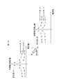
- the assembled battery control unit 150 and the cell management unit 120 transmit and receive signals by the signal communication unit 160 via an insulating element 170 such as a photocoupler.
- the reason why the insulating element 170 is provided is that the operating power supply differs between the assembled battery control unit 150 and the cell management unit 120. That is, while the cell management unit 120 operates by receiving electric power from the assembled battery 110, the assembled battery control unit 150 uses a battery for an in-vehicle auxiliary machine (for example, a 12V system battery) as a power source.
- the insulating element 170 may be mounted on the circuit board that constitutes the cell management unit 120, or may be mounted on the circuit board that constitutes the assembled battery control unit 150. Depending on the system configuration, the insulating element 170 may be omitted.
- the signal communication unit 160 between the assembled battery control unit 150 and the cell control units 121a and 121b in this embodiment will be described.
- the cell control units 121a and 121b are connected in series in descending order of potential of the cell groups 112a and 112b monitored by each.
- the signal transmitted by the assembled battery control unit 150 is input to the cell control unit 121a by the signal communication unit 160 via the insulating element 170.
- the output of the cell control unit 121a and the input of the cell control unit 121b are also connected by the signal communication unit 160 to transmit a signal.
- the cell control units 121a and 121b do not pass through the insulating element 170, but may pass through the insulating element 170. Then, the output of the cell control unit 121b is input to the assembled battery control unit 150 by the signal communication unit 160 via the insulating element 170. In this way, the assembled battery control unit 150 and the unit battery control units 121a and 121b are connected in a loop by the signal communication unit 160. This loop connection is sometimes called a daisy chain connection or the like.
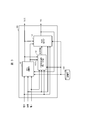
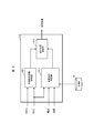
- FIG. 3 is a block diagram showing a configuration of an assembled battery control unit 150 constituting the battery system 100 of FIG. 1.
- the description of the processing content based on the diagnosis result regarding the cell 111 and the abnormal signal output when a communication error occurs in the cell management unit 120 is omitted for the sake of simplicity, and the SOC and SOH calculations are performed.
- the configuration for is described.
- the assembled battery control unit 150 includes an SOC calculation unit 151, an internal resistance calculation execution determination unit 152, and a SOH calculation unit 153.
- the SOC calculation unit 151 inputs SOC and SOCv by inputting the average voltage of each unit battery 111 constituting the assembled battery 110, the current flowing through the assembled battery 110, the temperature of the assembled battery 110, and the SOH output by the SOH calculation unit 153. Output.
- SOC and SOCv will be described later.
- the internal resistance calculation execution determination unit 152 inputs the average voltage of each unit battery 111 constituting the assembled battery 110, the current flowing through the assembled battery 110, the temperature of the assembled battery 110, and the SOC and SOCv output by the SOC calculation unit 151. , Judges whether the SOH operation can be executed and outputs the judgment result.
- the SOH calculation unit 153 calculates and outputs SOH by inputting the SOC and SOCv output by the SOC calculation unit 151 and the determination result output by the temperature, current, and internal resistance calculation execution determination unit 152. The calculated SOC and SOH are transmitted to the vehicle control unit 200.
- the storage unit 180 stores information such as the internal resistance characteristics of the assembled battery 110, the cell 111, and the cell group 112, the capacity when fully charged, the polarization resistance characteristic, the deterioration characteristic, the individual difference information, and the correspondence between SOC and OCV. To do.
- the storage unit 180 is configured to be installed outside the assembled battery control unit 150 or the cell management unit 120, but the storage unit is provided in the assembled battery control unit 150 or the cell management unit 120. May be done.
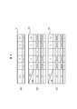
- FIG. 4 is a diagram showing a SOC table 181, an internal resistance table 182, and a polarization resistance table 183.
- the SOC table 181 and the internal resistance table 182, and the polarization resistance table 183 are stored in the storage unit 180.
- the SOC table 181 is a data table that describes the correspondence between the SOC of the cell 111 and the OCV (Open Circuit Voltage) according to the temperature.
- the internal resistance table 182 is a data table that describes the correspondence between the temperature of the cell 111 and the SOC and the initial resistance value of Ro, RoInit.
- the initial resistance value of Ro, RoInit is the resistance value of Ro when the battery is new when the cell 111 is represented by an equivalent circuit as shown in FIG.
- the polarization resistance table 183 is a data table that describes the correspondence between the temperature of the cell 111 and the SOC and the initial resistance value RpInit of Rp.
- the initial resistance value of Rp, RpInit is the resistance value of Rp when the battery is new when the cell 111 is represented by an equivalent circuit as shown in FIG.
- each correspondence may be expressed by a mathematical formula or the like, and the data table is not limited to the illustrated data table.
- FIG. 5 is a block diagram showing the configuration of the SOC calculation unit 151 constituting the assembled battery control unit 150 in the first embodiment.
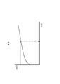
- FIG. 6 is a characteristic example showing the relationship between the SOC and OCV of the cell 111.
- the SOC calculation unit 151 includes a SOCi calculation unit 151-1, a SOCv calculation unit 151-2, and a combination calculation unit 151-3.
- the SOCi calculation unit 151-1 inputs the current and the previous value (calculation result of one cycle before) of the SOC calculation result output by the combination calculation unit 151-3, and inputs the SOC (hereinafter, SOCi) based on the integrated value of the current. Calculate and output.
- the SOCv calculation unit 151-2 calculates OCV based on the battery voltage, current, and temperature, and calculates SOC (hereinafter, SOCv) based on the correspondence between OCV and SOC shown in FIGS. 4A and 6. To do.
- the combination calculation unit 151-3 takes SOCi and SOCv as inputs, weights and averages SOCi and SOCv, and outputs them.
- SOCi is calculated by adding the amount of change in SOC due to the flow of current to the previous value (calculation result one cycle before) of the result output by the combination calculation unit 151-3, as shown in the following equation (1). Is calculated to.
- SOC_old is the previous value of SOC obtained by the formula (4) described later (calculation result one cycle before), I is the current, Qmax is the full charge capacity of the cell 111, and ts is the control cycle (current, voltage, etc.). Sampling period).
- FIG. 7 shows an equivalent circuit diagram of the cell 111
- FIG. 8 shows the behavior of the voltage when a charging current flows through the cell 111.
- the cell 111 is a model of a DC power supply simulating an OCV that represents the open circuit voltage of the battery, Ro that represents the electrical resistance of electrodes and electrolytes, and a resistance component (polarization component) that accompanies the electrochemical reaction of the battery. It has a circuit configuration in which a parallel circuit of Rp and C is connected in series.
- Ro and Rp contained in the above formula (2) are SOH_old, which is the rate of increase (%) of the internal resistance with respect to the initial resistance values RoInit and RpInit of the cell 111. Is the result of multiplying each.
- SOH_old in the following formula (3) is the previous value (calculation result one cycle before) obtained by the formula (6) described later.
- RoInit and RpInit in the above formula (3) are the results calculated based on the current SOC and temperature with reference to the internal resistance table 182 and the polarization resistance table 183 stored in the storage unit 180 in advance.
- the SOCv calculation unit 151-2 calculates the OCV from the first to third equations of the above equation (2), and corresponds to the OCV as shown in the fourth equation (a) and 6 (a). Calculate SOC as SOCv.
- the combination calculation unit 151-3 uses the SOCi calculated by the SOCi calculation unit 151-1, the SOCv calculated by the SOCv calculation unit 151-2, the current, and the temperature as inputs based on the following equation (4). Calculate the SOC.
- w indicates a weighting coefficient, for example, calculated from the following equation (5).
- the weighting coefficient as in the equation (5) is provided, but the weighting coefficient is not limited to this.
- FIG. 9 is a block diagram showing the configuration of the internal resistance calculation execution determination unit 152 in the first embodiment.
- the internal resistance calculation execution determination unit 152 uses the SOC and SOCv input from the SOC calculation unit 151 as inputs to determine whether or not the resistance value used in the SOCv calculation has an error of a predetermined value or more.
- Detection unit 152-1 and calculation execution judgment unit 152-2 that determines whether SOC, current, and voltage are within a predetermined range, internal resistance error detection unit 152-1 and calculation execution judgment unit 152-2, respectively.
- the correction possibility determination unit 152-3 for determining whether or not the internal resistance correction process can be executed is included.
- the internal resistance error detection unit 152-1 determines the internal resistance value used for the SOCv calculation. It is determined that there is a discrepancy with the internal resistance value of the battery to be controlled, and the determination result is output.
- the calculation execution determination unit 152-2 receives SOC, current, and temperature as inputs, and determines whether or not to execute the correction calculation of the internal resistance value. Specifically, it is checked whether the SOC, current, and temperature calculated by the SOC calculation unit 151 are within the predetermined range, and when the condition that all are within the predetermined range is satisfied, the calculation is possible, and the determination result is obtained. Is output.
- the predetermined ranges of SOC, current, and temperature are determined in consideration of the characteristics of the battery, the effects of SOC error, current, and temperature sensor error, and are stored in the storage unit 180.
- the correction possibility determination unit 152-3 determines whether or not to execute the correction calculation of the internal resistance based on the determination results of the internal resistance error detection unit 152-1 and the calculation execution determination unit 152-2. In this embodiment, when the resistance error is detected and the SOC, temperature, and current are within the predetermined range, the internal resistance correction calculation is executed, and in other cases, the internal resistance correction calculation is executed. do not.
- FIG. 10 is a block diagram showing a configuration of the SOH calculation unit according to the first embodiment.
- the SOH calculation unit 153 includes an internal resistance correction amount calculation unit 153-1, an internal resistance correction unit 153-2, and an SOH calculation unit 153-3.
- the internal resistance correction amount calculation unit 153-1 calculates the internal resistance correction amount based on the resistance correction amount map shown in FIG. 11 by inputting the SOC, SOCv, and current, and outputs the internal resistance correction amount to the internal resistance correction amount 153-2. ..
- the internal resistance correction unit 153-2 is stored in the storage unit 180 when it is determined that the calculation of the internal resistance correction amount can be executed by inputting the determination result of the internal resistance calculation execution determination unit 152, the SOC, and the temperature.
- the initial resistance value RoInit of the internal resistance Ro corresponding to the SOC and temperature in the internal resistance table 182 is corrected, and the corrected internal resistance value Ro is output to the SOH calculation unit 153-3.
- the SOH calculation unit 153-3 calculates SOH using the following formula (6) based on the corrected internal resistance value Ro and the initial resistance value RoInit corresponding to SOC and temperature.
- the corrected internal resistance value Ro may be used for various control of the battery in addition to the SOH calculation based on the following equation (6).
- SOH is the ratio of Ro and RoInit, but the ratio of Rp and RpInit corrected in the same manner as Ro may be used.
- the internal resistance correction unit 153-2 is internal when it is determined that the internal resistance calculation cannot be executed based on the determination result of either the internal resistance error detection unit 152-1 or the calculation execution determination unit 152-2.
- the resistance value is not corrected, that is, the internal resistance value calculated in the calculation cycle determined that the internal resistance calculation can be executed most recently is output. For example, when the calculation process is performed in a predetermined calculation cycle, when it is determined that the internal resistance calculation can be executed one cycle before the calculation cycle determined to be unexecutable, in the calculation cycle one cycle before.
- the calculated internal resistance value is output.
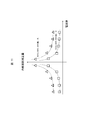
- FIG. 11 shows an example of a map of the resistance correction amount according to the current value and the SOC difference (SOCv-SOC).
- SOCv-SOC SOCv-SOC
- the resistance correction amount map may be constructed so that the correction amount is set to a large value.
- the internal resistance correction amount according to the SOC difference and the current shown in FIG. 11 may be stored in the storage unit 180 after the correction value is determined in advance as a map or a table, or the relationship is described by a mathematical formula. It may be implemented as a mathematical formula.
- FIG. 12 is a flowchart showing the SOH calculation process in the first embodiment.
- the SOH calculation process is repeatedly executed by the assembled battery control unit 150 until the electric system S including the battery system 100 is started and shut down.
- step S11 the assembled battery control unit 150 calculates the SOCi according to the above equation (1) in the SOCi calculation unit 151-1 of the SOC calculation unit 151.
- step S12 the assembled battery control unit 150 calculates SOCi according to the above equations (2) and (3) in the SOCv calculation unit 151-2 of the SOC calculation unit 151.
- step S13 the assembled battery control unit 150 calculates the SOC in the combination calculation unit 151-3 of the SOC calculation unit 151 according to the above equations (4) and (5).
- the assembled battery control unit 150 stores the SOC calculated in step S13 in the variable SOC_old.
- step S14 in the assembled battery control unit 150, whether the SOCv error (absolute value of the difference between SOC and SOCv) in the internal resistance error detection unit 152-1 of the internal resistance calculation execution determination unit 152 is equal to or higher than a predetermined value. It is determined whether or not, and whether or not all of the input SOC, current, and temperature are within a predetermined range is determined by the calculation execution determination unit 152-2.
- the assembled battery control unit 150 determines that the correction possibility determination unit 152-3 of the internal resistance calculation execution determination unit 152 executes the internal resistance correction calculation when the determination result in step S14 is Yes, and proceeds to step S15. If the determination result in step S14 is No, it is determined that the internal resistance correction calculation is not executed, and the process is returned to step S11.
- step S15 the assembled battery control unit 150 inputs SOC, SOCv, and current in the internal resistance correction amount calculation unit 153-1 of the SOH calculation unit 153 to correct the internal resistance from the internal resistance correction amount map shown in FIG. Calculate the quantity.
- step S16 the assembled battery control unit 150 inputs the determination result, SOC and temperature of the internal resistance calculation execution determination unit 152 in the internal resistance correction unit 153-2 of the SOH calculation unit 153, and sets the internal resistance table 182.
- the corrected internal resistance value Ro obtained by correcting the initial resistance value RoInit corresponding to the SOC and temperature based on the first equation of the above equation (3) is output to the SOH calculation unit 153-3.
- step S17 the assembled battery control unit 150 determines the above equation (6) based on the corrected internal resistance value Ro and the initial resistance value RoInit corresponding to the SOC and temperature in the SOH calculation unit 153-3. Calculate SOH from.
- the assembled battery control unit 150 stores the SOH calculated in step S18 in the variable SOH_old.
- step S18 the assembled battery control unit 150 determines whether or not the electric system S including the battery system 100 is shut down, and if it is shut down (step S18: Yes), the present SOH calculation process is terminated. If the system is not shut down (step S18: No), the process returns to step S11.
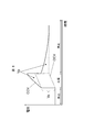
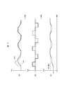
- FIG. 13 is a diagram showing a profile of SOH calculation at the time of charge / discharge pulse input in the prior art.
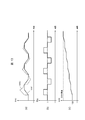
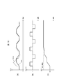
- FIG. 14 is a diagram showing a profile of SOH calculation at the time of charge / discharge pulse input in the first embodiment.
- FIGS. 13 and 14 show the calculation of (a) SOC calculation value, (b) current, and (c) SOH (internal resistance increase rate) when the charge / discharge current of a square wave that repeats charging or discharging is input, respectively.
- the waveform of the value is shown.
- FIG. 13 shows the result of the conventional method (fixed value of resistance correction amount) before applying the present invention
- FIG. 14 shows the result when the present invention is applied.
- the initial value of SOH is set to 100%, and it is assumed that there is a large deviation from the true value.
- the SOC (SOCv) waveform based on the internal resistance is subjected to the SOC calculation due to the influence of the SOH calculation error (internal resistance error).
- SOH calculation error internal resistance error
- the difference between SOCv and SOC is extracted, the internal resistance is corrected by a fixed value, and the SOH calculated value is gradually updated (FIG. 13 (c)).
- the SOCv approaches the SOC calculated value, that is, the SOC difference becomes smaller, and at the end of charging / discharging, the SOH calculated value converges to the SOH true value, and the SOC The difference is also small.
- FIG. 14 shows the SOC, current, and SOH waveforms when the present invention is applied.
- the SOC waveform shown in FIG. 14 (a) in the region immediately after the start of charging / discharging, the SOCv waveform deviates from the SOC due to the influence of the SOH error, as in the conventional technique shown in FIG. It turns out that is large.
- the difference between SOCv and SOC is extracted and the internal resistance is corrected.
- the resistance correction amount map as shown in FIG. 11 the larger the SOC difference, the larger the internal resistance correction amount. It can be seen that the update speed at which SOH approaches the true value is faster than with the conventional method.
- the internal resistance is used by using the difference between the SOC (SOCv) based on the internal resistance and the SOC calculated by a method different from the SOCv and the internal resistance correction amount determined based on the current value.
- the resistance correction amount can be adjusted in a state where the difference between the SOH recognized by the battery control device and the true SOH value of the controlled battery is large. Since it can be set large, the convergence of the SOH calculated value is improved. Further, when the SOH calculated value is updated and approaches the true value, the correction amount of the internal resistance value becomes smaller, so that the SOH can be calculated accurately without impairing the stability. As a result, it is possible to achieve both calculation accuracy and convergence, so that the power that can be input and output of the battery can be accurately grasped, and the index of battery replacement can be accurately calculated.
- Example 2 of the present invention will be described with reference to FIGS. 15 and 16.
- the correction amount of the internal resistance value is controlled based on the difference between the SOC (SOCv) calculated based on the resistance, the SOC (SOCi) based on the current, and the SOC obtained by the combination of the SOCv, and the current value. Described how to do it.
- the temperature of the battery is further added to control the amount of internal resistance correction.
- the differences from the first embodiment will be mainly described, and the description of the parts having the same configuration as that of the first embodiment will be omitted.
- the difference from the first embodiment in this embodiment is that the assembled battery control unit 150 has the SOH calculation unit 153B instead of the SOH calculation unit 153.
- the SOH calculation unit 153B will be described.
- FIG. 15 is a block diagram showing the configuration of the SOH calculation unit 153B in the second embodiment.
- the SOH calculation unit 153B includes an internal resistance correction amount calculation unit 153-1B instead of the internal resistance correction amount calculation unit 153-1.
- the internal resistance correction amount calculation unit 153-1B calculates the internal resistance correction amount by inputting the SOC difference, the current, and the temperature, and outputs the internal resistance correction amount to the internal resistance correction unit 153-2.
- FIG. 16 is a diagram showing an internal resistance correction amount map in the second embodiment, and shows an internal resistance correction amount corresponding to the SOC difference for each temperature T.
- the internal resistance of a battery tends to decrease as the temperature rises. Therefore, if a uniform internal resistance correction amount is set according to the temperature T, the internal resistance correction amount may be too large with respect to the internal resistance value itself.
- the SOH value fluctuates greatly and may vibrate. ..
- the internal resistance correction amount is too small with respect to the internal resistance value, the change in the SOH value becomes small, so that the speed of convergence of the SOH calculated value to the true value may decrease.
- the internal resistance correction amount is set to a small value as a whole in the high temperature region where the internal resistance value is smaller than that of the resistance correction amount map shown in FIG.
- the internal resistance correction amount is set to a large value as a whole. That is, in this embodiment, the larger the difference between the SOC calculated value (SOCv) based on the internal resistance and the SOC calculated by a method different from SOCv, and the smaller the absolute value of the current value, the smaller.
- the higher the temperature of the battery the larger the internal resistance correction amount is set so that the resistance correction amount map is constructed.
- the internal resistance correction amount according to the SOC difference, the current, and the temperature shown in FIG. 16 may be stored in the storage unit 180 by determining the correction value in advance as a map or a table, or the relationship may be expressed by a mathematical formula. It may be described and implemented as a mathematical formula.
- FIG. 17 and 18 show the calculation of (a) SOC calculation value, (b) current, and (c) SOH (internal resistance increase rate) when the charge / discharge current of a square wave that repeats charging or discharging is input, respectively.
- the waveform of the value is shown.
- FIG. 17 shows an example of the calculation result when the SOH calculation is executed in the high temperature region (for example, 50 ° C.) using the internal resistance correction amount set in the normal temperature region (for example, 25 ° C.).
- the internal resistance is determined by using the difference between the SOC based on the internal resistance (SOCv) and the SOC calculated by a method different from the SOCv, the current value, and the internal resistance correction amount determined according to the temperature.
- the internal resistance correction amount may be determined according to the degree of deterioration. That is, as in the resistance correction amount map in the modified example of the second embodiment shown in FIG. 19, the deterioration degree SOH is small and the internal resistance is small when the product is new, as compared with the resistance correction amount map shown in FIG. The internal resistance correction amount is reduced as a whole, and if the deterioration degree SOH increases and the internal resistance increases as the deterioration progresses, the internal resistance correction amount is increased as a whole.
- the internal resistance correction amount according to the SOC difference, the current, and the degree of deterioration shown in FIG. 19 may be determined in advance as a map or a table and stored in the storage unit 180, or the relationship may be mathematically expressed. It may be described in and implemented as a mathematical formula.
- the internal resistance can be corrected with an internal resistance correction amount suitable for ensuring stability and convergence according to the degree of deterioration of the battery, and as a result, the stability and convergence of the SOH calculated value are compatible. It becomes possible.
- S ... electric system 100 ... battery system, 110 ... assembled battery, 111 ... single battery, 112 ... single battery group, 120 ... single battery management unit, 121 ... single battery control unit, 122 ... voltage detection circuit, 123 ... Control circuit, 124 ... Signal input / output circuit, 125 ... Temperature detection unit, 130 ... Current detection unit, 140 ... Voltage detection unit, 150 ... Battery control unit, 151 ... SOC calculation unit, 151-1 ... SOCi calculation unit, 151 -2 ... SOCv calculation unit, 151-3 ... Combination calculation unit, 152 ... Internal resistance calculation execution judgment unit, 152-1 ... Internal resistance error detection unit, 152-2 ... Calculation execution judgment unit, 152-3 ...
- Correction availability judgment Unit 152-4 ... Energization time measurement unit, 153 ... SOH calculation unit, 153-1 ... Internal resistance correction amount calculation unit, 153-2 ... Internal resistance correction unit, 153-3 ... SOH calculation unit, 160 ... Signal communication unit , 170 ... Insulation element, 180 ... Storage unit, 200 ... Vehicle control unit, 300, 310 ... Relay, 400 ... Inverter, 410 ... Motor, 420 ... Motor / Inverter control unit
Landscapes
- Engineering & Computer Science (AREA)
- General Physics & Mathematics (AREA)
- Physics & Mathematics (AREA)
- Chemical Kinetics & Catalysis (AREA)
- Chemical & Material Sciences (AREA)
- Electrochemistry (AREA)
- General Chemical & Material Sciences (AREA)
- Manufacturing & Machinery (AREA)
- Microelectronics & Electronic Packaging (AREA)
- Power Engineering (AREA)
- Aviation & Aerospace Engineering (AREA)
- Secondary Cells (AREA)
- Charge And Discharge Circuits For Batteries Or The Like (AREA)
Abstract
Description


Claims (10)
- 電池の電流値、電圧値、及び内部抵抗値に基づいて、第1の手法で前記電池の第1充電状態を演算する第1演算部と、
前記第1の手法とは異なる第2の手法で前記電池の第2充電状態を演算する第2演算部と、
前記内部抵抗値を補正する補正部と、を含み、
前記補正部は、前記第1充電状態と前記第2充電状態との間に所定値以上の差分が検出された場合に、前記差分と前記電流値とに応じた抵抗補正量で、前記内部抵抗値を補正する、
ことを特徴とする電池制御装置。 - 請求項1に記載の電池制御装置において、
前記補正部によって補正された前記内部抵抗値に基づいて、前記電池の劣化度を演算する劣化度演算部
をさらに含んだことを特徴とする電池制御装置。 - 請求項1に記載の電池制御装置において、
前記補正部は、さらに前記第2充電状態、前記電流値、及び前記電池の温度が所定条件を充足する場合に、前記抵抗補正量で前記内部抵抗値を補正する、
ことを特徴とする電池制御装置。 - 請求項3に記載の電池制御装置において、
前記補正部は、前記差分が検出されない、または、前記第2充電状態が前記所定条件を充足しない場合には、前記内部抵抗値を補正せず、前記差分が検出され、かつ、前記第2充電状態、前記電流値、及び前記電池の温度が前記所定条件を充足すると判定された直近の演算周期において補正した前記内部抵抗値を出力する、
ことを特徴とする電池制御装置。 - 請求項1に記載の電池制御装置において、
前記抵抗補正量は、前記差分が大きいほど、かつ、前記電流値の絶対値が小さいほど、大きな値である、
ことを特徴とする電池制御装置。 - 請求項5に記載の電池制御装置において、
前記抵抗補正量は、さらに前記電池の温度に応じた値である、
ことを特徴とする電池制御装置。 - 請求項6に記載の電池制御装置において、
前記抵抗補正量は、前記電池の温度が高いほど、小さな値である
ことを特徴とする電池制御装置。 - 請求項5に記載の電池制御装置において、
前記抵抗補正量は、さらに前記電池の劣化度に応じた値である、
ことを特徴とする電池制御装置。 - 請求項8に記載の電池制御装置において、
前記抵抗補正量は、前記電池の劣化度が大きいほど、大きな値である、
ことを特徴とする電池制御装置。 - 請求項1~9の何れか1項に記載の電池制御装置と、
前記電池が複数接続された組電池と、
前記抵抗補正量を記憶する記憶部と、を有し、
前記電池制御装置は、前記記憶部に記憶されている前記抵抗補正量をもとに前記内部抵抗値を補正し、前記電池及び前記組電池を制御する、
ことを特徴とする電池システム。
Priority Applications (4)
| Application Number | Priority Date | Filing Date | Title |
|---|---|---|---|
| US17/789,494 US12424673B2 (en) | 2019-12-26 | 2020-09-18 | Battery control apparatus and battery system |
| CN202080090727.7A CN115336084B (zh) | 2019-12-26 | 2020-09-18 | 电池控制装置及电池系统 |
| JP2021566820A JP7605766B2 (ja) | 2019-12-26 | 2020-09-18 | 電池制御装置及び電池システム |
| EP20906768.5A EP4084187A4 (en) | 2019-12-26 | 2020-09-18 | Battery control device and battery system |
Applications Claiming Priority (2)
| Application Number | Priority Date | Filing Date | Title |
|---|---|---|---|
| JP2019-237407 | 2019-12-26 | ||
| JP2019237407 | 2019-12-26 |
Publications (1)
| Publication Number | Publication Date |
|---|---|
| WO2021131184A1 true WO2021131184A1 (ja) | 2021-07-01 |
Family
ID=76575287
Family Applications (1)
| Application Number | Title | Priority Date | Filing Date |
|---|---|---|---|
| PCT/JP2020/035632 Ceased WO2021131184A1 (ja) | 2019-12-26 | 2020-09-18 | 電池制御装置及び電池システム |
Country Status (5)
| Country | Link |
|---|---|
| US (1) | US12424673B2 (ja) |
| EP (1) | EP4084187A4 (ja) |
| JP (1) | JP7605766B2 (ja) |
| CN (1) | CN115336084B (ja) |
| WO (1) | WO2021131184A1 (ja) |
Cited By (2)
| Publication number | Priority date | Publication date | Assignee | Title |
|---|---|---|---|---|
| WO2023042718A1 (ja) * | 2021-09-14 | 2023-03-23 | 株式会社Gsユアサ | 管理装置、蓄電装置、管理方法及びプログラム |
| JP2023107661A (ja) * | 2022-01-24 | 2023-08-03 | 本田技研工業株式会社 | 蓄電システム |
Families Citing this family (5)
| Publication number | Priority date | Publication date | Assignee | Title |
|---|---|---|---|---|
| EP3960532B1 (en) * | 2020-08-27 | 2024-11-13 | Ningbo Geely Automobile Research & Development Co. Ltd. | A power supply system for an electric vehicle drivetrain |
| JP7540403B2 (ja) | 2021-06-29 | 2024-08-27 | 株式会社デンソー | 電池測定装置及び電池測定方法 |
| DE102021214161A1 (de) * | 2021-12-10 | 2023-06-15 | Robert Bosch Gesellschaft mit beschränkter Haftung | Verfahren und Vorrichtung zum Bereitstellen eines Alterungszustands für eine Gerätebatterie mit Korrektur von Zustandsbeobachtungen auf Basis systematischer Zustands- und Umgebungseinflüsse |
| JP7775720B2 (ja) * | 2022-01-20 | 2025-11-26 | 株式会社デンソー | 二次電池システム |
| CN115951240B (zh) * | 2022-08-25 | 2026-03-13 | 上海美克生能源科技有限公司 | 动力电池的性能确定方法及装置、电子设备及存储介质 |
Citations (2)
| Publication number | Priority date | Publication date | Assignee | Title |
|---|---|---|---|---|
| JP2010256323A (ja) * | 2009-03-31 | 2010-11-11 | Hitachi Ltd | 電源装置用状態検知装置 |
| WO2017199629A1 (ja) * | 2016-05-18 | 2017-11-23 | 日立オートモティブシステムズ株式会社 | 電池制御装置 |
Family Cites Families (3)
| Publication number | Priority date | Publication date | Assignee | Title |
|---|---|---|---|---|
| JP5601761B2 (ja) * | 2008-06-09 | 2014-10-08 | 住友重機械工業株式会社 | ハイブリッド型作業機械 |
| KR20120138733A (ko) * | 2010-03-05 | 2012-12-26 | 파나소닉 주식회사 | 만충전 용량값 보정 회로, 전지 팩, 및 충전 시스템 |
| JP6615011B2 (ja) * | 2016-03-09 | 2019-12-04 | 日立オートモティブシステムズ株式会社 | 電池管理システム、電池システムおよびハイブリッド車両制御システム |
-
2020
- 2020-09-18 CN CN202080090727.7A patent/CN115336084B/zh active Active
- 2020-09-18 EP EP20906768.5A patent/EP4084187A4/en active Pending
- 2020-09-18 US US17/789,494 patent/US12424673B2/en active Active
- 2020-09-18 WO PCT/JP2020/035632 patent/WO2021131184A1/ja not_active Ceased
- 2020-09-18 JP JP2021566820A patent/JP7605766B2/ja active Active
Patent Citations (3)
| Publication number | Priority date | Publication date | Assignee | Title |
|---|---|---|---|---|
| JP2010256323A (ja) * | 2009-03-31 | 2010-11-11 | Hitachi Ltd | 電源装置用状態検知装置 |
| JP5439126B2 (ja) | 2009-03-31 | 2014-03-12 | 株式会社日立製作所 | 電源装置用状態検知装置 |
| WO2017199629A1 (ja) * | 2016-05-18 | 2017-11-23 | 日立オートモティブシステムズ株式会社 | 電池制御装置 |
Non-Patent Citations (1)
| Title |
|---|
| See also references of EP4084187A4 |
Cited By (6)
| Publication number | Priority date | Publication date | Assignee | Title |
|---|---|---|---|---|
| WO2023042718A1 (ja) * | 2021-09-14 | 2023-03-23 | 株式会社Gsユアサ | 管理装置、蓄電装置、管理方法及びプログラム |
| JP2023042406A (ja) * | 2021-09-14 | 2023-03-27 | 株式会社Gsユアサ | 管理装置、蓄電装置、管理方法及びプログラム |
| JP7605070B2 (ja) | 2021-09-14 | 2024-12-24 | 株式会社Gsユアサ | 管理装置、蓄電装置、管理方法及びプログラム |
| JP2025031738A (ja) * | 2021-09-14 | 2025-03-07 | 株式会社Gsユアサ | 管理装置、蓄電装置、管理方法及びプログラム |
| JP2023107661A (ja) * | 2022-01-24 | 2023-08-03 | 本田技研工業株式会社 | 蓄電システム |
| JP7547400B2 (ja) | 2022-01-24 | 2024-09-09 | 本田技研工業株式会社 | 蓄電システム |
Also Published As
| Publication number | Publication date |
|---|---|
| JPWO2021131184A1 (ja) | 2021-07-01 |
| JP7605766B2 (ja) | 2024-12-24 |
| CN115336084B (zh) | 2025-09-19 |
| EP4084187A1 (en) | 2022-11-02 |
| EP4084187A4 (en) | 2024-05-15 |
| CN115336084A (zh) | 2022-11-11 |
| US12424673B2 (en) | 2025-09-23 |
| US20230039183A1 (en) | 2023-02-09 |
Similar Documents
| Publication | Publication Date | Title |
|---|---|---|
| JP7605766B2 (ja) | 電池制御装置及び電池システム | |
| JP6588632B2 (ja) | 電池制御装置 | |
| JP6496810B2 (ja) | 電池制御装置、および電動車両システム | |
| US12252021B2 (en) | Method for estimating an operating parameter of a battery unit | |
| KR102335296B1 (ko) | 무선 네트워크 기반 배터리 관리 시스템 | |
| EP3002597B1 (en) | Battery control device | |
| CN106030326B (zh) | 二次电池系统 | |
| CN106662620B (zh) | 电池状态探测装置、二次电池系统、存储介质、电池状态探测方法 | |
| WO2016009757A1 (ja) | 電池状態検知装置、二次電池システム、プログラム製品、電池状態検知方法 | |
| JP7594440B2 (ja) | 電池制御装置 | |
| CN109669131B (zh) | 一种工况环境下动力电池soc估算方法 | |
| WO2017056732A1 (ja) | 電池制御装置及び電池システム | |
| US20240210478A1 (en) | Apparatus and method for managing battery | |
| JP7741971B2 (ja) | 電池制御装置及び電池制御方法 | |
| WO2013057784A1 (ja) | 電池制御装置、二次電池システム | |
| EP4283318B1 (en) | Method and device for estimating state of charge of a battery | |
| US11680989B2 (en) | Diagnosis method of battery, diagnosis device of battery, diagnosis system of battery, battery-mounted device, and non-transitory storage medium | |
| WO2024028955A1 (ja) | 電池制御方法、電池制御装置、及び車両制御方法 | |
| CN114252778A (zh) | 用于根据电池的老化状态单独确定电池驱动的机器的电池的荷电状态的方法和装置 | |
| JP7592357B2 (ja) | 内部抵抗評価装置およびバッテリシステム | |
| Bhat et al. | Electrolyte based Equivalent Circuit Model of Lithium ion Batteries for Intermittent Load Applications | |
| KR20240171900A (ko) | 배터리 상태 예측 장치 및 그것의 동작 방법 | |
| JP2025158270A (ja) | バッテリーマネージメントシステム、および、バッテリーマネージメント方法 |
Legal Events
| Date | Code | Title | Description |
|---|---|---|---|
| 121 | Ep: the epo has been informed by wipo that ep was designated in this application |
Ref document number: 20906768 Country of ref document: EP Kind code of ref document: A1 |
|
| DPE1 | Request for preliminary examination filed after expiration of 19th month from priority date (pct application filed from 20040101) | ||
| ENP | Entry into the national phase |
Ref document number: 2021566820 Country of ref document: JP Kind code of ref document: A |
|
| NENP | Non-entry into the national phase |
Ref country code: DE |
|
| ENP | Entry into the national phase |
Ref document number: 2020906768 Country of ref document: EP Effective date: 20220726 |
|
| WWG | Wipo information: grant in national office |
Ref document number: 202080090727.7 Country of ref document: CN |
|
| WWG | Wipo information: grant in national office |
Ref document number: 17789494 Country of ref document: US |