WO2021131274A1 - Élément conducteur - Google Patents
Élément conducteur Download PDFInfo
- Publication number
- WO2021131274A1 WO2021131274A1 PCT/JP2020/039357 JP2020039357W WO2021131274A1 WO 2021131274 A1 WO2021131274 A1 WO 2021131274A1 JP 2020039357 W JP2020039357 W JP 2020039357W WO 2021131274 A1 WO2021131274 A1 WO 2021131274A1
- Authority
- WO
- WIPO (PCT)
- Prior art keywords
- braided wire
- bus bar
- welded
- conductive member
- wire
- Prior art date
- Legal status (The legal status is an assumption and is not a legal conclusion. Google has not performed a legal analysis and makes no representation as to the accuracy of the status listed.)
- Ceased
Links
Images





Classifications
-
- H—ELECTRICITY
- H01—ELECTRIC ELEMENTS
- H01B—CABLES; CONDUCTORS; INSULATORS; SELECTION OF MATERIALS FOR THEIR CONDUCTIVE, INSULATING OR DIELECTRIC PROPERTIES
- H01B5/00—Non-insulated conductors or conductive bodies characterised by their form
- H01B5/02—Single bars, rods, wires, or strips
-
- H—ELECTRICITY
- H01—ELECTRIC ELEMENTS
- H01B—CABLES; CONDUCTORS; INSULATORS; SELECTION OF MATERIALS FOR THEIR CONDUCTIVE, INSULATING OR DIELECTRIC PROPERTIES
- H01B5/00—Non-insulated conductors or conductive bodies characterised by their form
- H01B5/12—Braided wires or the like
-
- H—ELECTRICITY
- H01—ELECTRIC ELEMENTS
- H01R—ELECTRICALLY-CONDUCTIVE CONNECTIONS; STRUCTURAL ASSOCIATIONS OF A PLURALITY OF MUTUALLY-INSULATED ELECTRICAL CONNECTING ELEMENTS; COUPLING DEVICES; CURRENT COLLECTORS
- H01R4/00—Electrically-conductive connections between two or more conductive members in direct contact, i.e. touching one another; Means for effecting or maintaining such contact; Electrically-conductive connections having two or more spaced connecting locations for conductors and using contact members penetrating insulation
- H01R4/02—Soldered or welded connections
Definitions
- the present invention relates to a conductive member that electrically connects and conducts a plurality of devices.
- Patent Document 1 discloses a conductive member composed of a bus bar formed of a metal plate and a braided wire formed by knitting a metal wire.
- the bus bar and the braided wire are connected by welding.
- the bus bar and the braided wire when the bus bar and the braided wire are welded with the braided wire simply overlapped on the bus bar, a part of the braided wire melts down at the welded portion and a part of the metal wire constituting the braided wire is broken. May be done.
- the use of the conductive member may cause the braided wire to be unwound from the broken portion or torn at the broken end, and the durability performance of the conductive member may be deteriorated.
- An object of the present invention is to provide a conductive member having improved durability performance.
- a conductive member having a bus bar composed of a metal plate and a braided wire in which a metal wire is woven is provided.
- the braided wire is placed on the surface of the busbar and welded to the busbar.
- the welded portion for welding the bus bar and the braided wire is arranged in an intermediate portion excluding both end portions in the width direction of the braided wire.
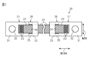
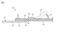
- Side view of the conductive member The perspective view which shows the formation process of the conductive member.
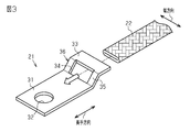
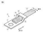
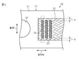
- the perspective view which shows the formation process of the conductive member. The plan view which shows the welded part and its surroundings enlarged.
- the plan view which shows the weld part of the modification. The plan view which shows the weld part of the modification.
- the conductive member 20 has a pair of bus bars 21 made of a metal plate and a braided wire 22 in which a metal wire is woven. Each of the pair of bus bars 21 is fixed to each end of the braided wire 22.
- the bus bar 21 has a flat plate portion 31 extending from the center of the bus bar 21 in the longitudinal direction to one end.
- the flat plate portion 31 is provided with a through hole having a circular cross section as a terminal hole 32.
- the terminal hole 32 is used when connecting the conductive member 20 to the terminal of the electric device.
- the bus bar 21 has a bent portion 33 bent in a stepped shape in a portion other than the flat plate portion 31.
- the bent portion 33 is a portion in which the bus bar 21 is bent in a crank shape in a cross-sectional view.
- the bus bar 21 has a through hole 34 penetrating the bent portion 33.
- the through hole 34 has a substantially rectangular cross section.
- the bent portion 33 has a wall portion extending in the vertical direction, specifically, a stepped wall portion 35 extending in the thickness direction of the flat plate portion 31.
- the through hole 34 penetrates the stepped wall portion 35.
- the braided wire 22 is inserted through the through hole 34 of the bus bar 21.
- a portion of the bus bar 21 including the inner edge of the through hole 34 is formed as an annular portion 36.
- the annular portion 36 extends in an annular shape over the entire circumference of the braided wire 22.
- the annular portion 36 is composed of the entire bent portion 33.
- the flat plate portion 31 of the bus bar 21 and the end portion of the braided wire 22 are overlapped in the vertical direction.
- the laser is irradiated from above the braided wire 22, that is, from above in FIG. 2, and welded.
- the end portion of the braided wire 22 is fixed to the flat plate portion 31 of the bus bar 21.
- Both ends of the braided wire 22 are cut surfaces cut by laser processing. On this cut surface, the metal wires constituting the braided wire 22 are melted and integrated. This makes it difficult to unravel both ends of the braided wire 22.
- the welded portion 23 to which the bus bar 21 and the braided wire 22 are welded is defined as follows.
- the welded portion 23 is arranged apart from the tip end in the longitudinal direction of the braided wire 22, and is arranged in an intermediate portion excluding both end portions in the width direction (vertical direction of FIG. 1) of the braided wire 22. Further, the plurality of welded portions 23 extend linearly in the width direction of the braided wire 22 in a plan view, and are arranged at intervals in the longitudinal direction of the braided wire 22 (horizontal direction in FIG. 1).
- the conductive member 20 is provided with three welded portions 23 extending in parallel.
- the end portion of the braided wire 22 is inserted into the through hole 34 of the bus bar 21. Then, as shown in FIG. 4, the end portion of the braided wire 22 is superposed on the flat plate portion 31 of the bus bar 21. After that, the end of the braided wire 22 is fixed to the flat plate portion 31 of the bus bar 21 by irradiating the laser from above the braided wire 22, that is, from above in FIG. 4 and welding. By fixing the bus bars 21 at both ends of the braided wire 22 in this way, the conductive member 20 is formed.
- the welded portion 23 between the bus bar 21 and the braided wire 22 is an intermediate portion excluding both end portions (the portion indicated by “A” in FIG. 5) in the width direction of the braided wire 22. Have been placed.
- the metal material melted by welding (specifically, the melt of the metal wire constituting the braided wire 22) is not welded at both ends of the braided wire 22. It is dammed by part A. This makes it difficult for the metal material to flow out beyond the outer edge of the braided wire 22 in the width direction. Therefore, the metal material can be fastened inside the braided wire 22.
- the welded portion 23 in the braided wire 22 is compared with the case where the metal material flows out beyond the outer edge in the width direction of the braided wire 22 as shown by the alternate long and short dash line in FIG.
- the included part does not become thinner than necessary. Therefore, the braided wire 22 can be welded and fixed to the bus bar 21 so that all the metal wires constituting the braided wire 22 are joined to each other.
- inconveniences such as the metal wire constituting the braided wire 22 being unraveled or the cut end of the metal wire being torn off and becoming a foreign substance do not occur with the use of the conductive member 20.
- the durability performance of the conductive member 20 is improved.
- the metal wire of the braided wire 22 passing through the portion is not welded to the bus bar 21, and the conduction performance of the conductive member 20 may be deteriorated. ..
- the welded portion 23 for welding the bus bar 21 and the braided wire 22 is linear and continuous in the width direction in the plan view at the intermediate portion of the braided wire 22 except for both end portions A in the width direction. And is extending. Therefore, all the metal wires passing through the intermediate portion in the width direction of the braided wire 22, in other words, the portion other than the both end portions A in the width direction of the braided wire 22, can be welded to the bus bar 21.
- each metal wire constituting the braided wire 22 passes through both end portions A of the braided wire 22 in a certain portion and passes through an intermediate portion of the braided wire 22 in another portion.
- the three welded portions 23 are lined up at intervals in the longitudinal direction of the braided wire 22 and extend in parallel with each other.
- the metal wire that is not welded to the bus bar 21 because it passes through both end portions A of the braided wire 22 is passed through the intermediate portion of the braided wire 22 to the other welded portion. It can be welded to 23 and fixed to the bus bar 21.
- the shape and spacing of the welded portions 23 are determined so that all the metal wires constituting the braided wire 22 are welded to at least one of the three welded portions 23 and fixed to the bus bar 21. There is. Therefore, all the metal wires constituting the braided wire 22, that is, the woven metal wires can be welded and fixed to the bus bar 21. Therefore, the conduction performance of the conduction member 20 can be improved.
- the flat plate portion 31 of the bus bar 21 and the end portion of the braided wire 22 are welded and fixed in a vertically overlapped state. Therefore, as shown by an arrow B in FIG. 6, when the braided wire 22 is deformed so as to be peeled off from the bus bar 21, the welded portion 23 of the bus bar 21 and the braided wire 22 is stressed in the direction of peeling both. It works. This is not preferable for improving the durability performance of the welded portion 23.
- the portion of the bus bar 21 including the inner edge of the through hole 34 is the annular portion 36.
- the annular portion 36 extends in an annular shape over the entire circumference of the braided wire 22. Therefore, when the braided wire 22 is deformed so as to be peeled off from the bus bar 21, the outer surface of the braided wire 22 (the upper surface of the braided wire 22 shown in FIG. 6) is pressed against the inner edge of the annular portion 36 of the bus bar 21. Specifically, the outer surface of the braided wire 22 is pressed against the outer surface of the bent portion 33, that is, the lower surface of the bent portion 33 shown in FIG.
- the portion where the outer surface of the braided wire 22 is pressed when the braided wire 22 is deformed is subjected to surface pressing processing or the like. It is preferable to have a rounded shape. As a result, the braided wire 22 is not rubbed against the corner portion of the bus bar 21 and is not damaged.
- the welded portion 23 between the bus bar 21 and the braided wire 22 is arranged at an intermediate portion excluding both end portions A in the width direction of the braided wire 22. Therefore, the durability performance of the conductive member 20 is improved.
- the welded portion 23 extends linearly in the width direction of the braided wire 22. Therefore, most of the metal wires passing through the intermediate portion in the width direction of the braided wire 22 can be welded to the bus bar 21. Thereby, the conduction performance of the conduction member 20 can be improved.
- Three welded portions 23 are lined up at intervals in the longitudinal direction of the braided wire 22 and extend in parallel with each other. Therefore, all the metal wires constituting the braided wire 22, that is, the woven metal wires can be welded and fixed to the bus bar 21. Thereby, the conduction performance of the conduction member 20 can be improved.
- the portion of the bus bar 21 including the inner edge of the through hole 34 is the annular portion 36.
- the annular portion 36 extends in an annular shape over the entire circumference of the braided wire 22. Therefore, the durability of the welded portion 23 for welding the bus bar 21 and the braided wire 22, and thus the conductive member 20, is improved.
- the annular portion 36 can be realized with a simple structure such as a bent portion 33 bent in a stepped shape and a through hole 34. Thereby, the bus bar 21 having the annular portion 36 can be easily formed by press working.
- the shape of the welded portion 23 can be arbitrarily changed as long as it is arranged in an intermediate portion excluding both end portions A in the width direction. Specifically, the arrangement mode of the welded portion illustrated in FIGS. 7 to 9 below can be adopted.
- the three welded portions 43 extend linearly in a direction inclined with respect to the width direction of the braided wire 22 (vertical direction in FIG. 7).
- the welded portions 43 are arranged at intervals in the longitudinal direction of the braided wire 22 and extend in parallel with each other.
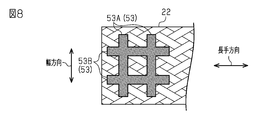
- the welded portions 53 are arranged in a grid pattern in a plan view.
- a pair of welded portions 53A extending parallel to the width direction and a pair of welded portions 53B extending parallel to the longitudinal direction intersect with each other.
- nine welded portions 63 are arranged in a dot shape in a plan view.
- the circular welded portions 63 are arranged in three rows in each of the width direction and the longitudinal direction.
- the bus bar may be formed in an L-shaped cross section.
- the bus bar has a flat plate portion 31 and a flat plate-shaped standing wall portion extending in a direction intersecting the flat plate portion 31.
- the bus bar has a through hole in the vertical wall portion.
- the end portion of the braided wire 22 may be welded to the outer surface of the flat plate portion 31 and fixed in a state where the braided wire 22 is inserted into the through hole of the vertical wall portion.
- the inner edge of the through hole in the bus bar can be an annular portion extending in an annular shape over the entire circumference of the braided wire 22.
- the annular portion can be realized by a simple structure such as an L-shaped bent portion and a through hole. Therefore, a bus bar having an annular portion can be easily formed by press working.
- the annular portion is not limited to being formed only by the bus bar 21, but may be formed by the bus bar main body and a member different from the bus bar main body.
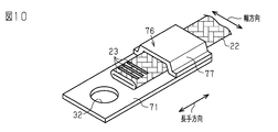
- the bridging portion 77 may be fixed to the bus bar main body 71 in such a manner that the outer surface of the bus bar main body 71 is covered with the bridging portion 77 having a hat-shaped cross section.
- the tubular portion formed by the bus bar main body 71 and the bridging portion 77 can be formed into an annular portion 76 extending in an annular shape over the entire circumference of the braided wire 22.
- the conductive member according to the above embodiment is welded to the bus bar 81 from the outer surface of the braided wire 82 with the end of the bus bar 81 inserted inside the tubular braided wire 82. It may be a conductive member 80 to which the braided wire 82 is fixed.
- the welded portion 83 for welding the bus bar 81 and the braided wire 82 may be arranged at an intermediate portion excluding both end portions in the width direction of the braided wire 82.
- the corner portion on the outer surface of the end portion of the bus bar 81 specifically, the corner portion pressed against the inner surface of the braided wire 82 when the bus bar 81 is inserted into the inside of the braided wire 82 is rounded by surface pressing. It is preferably shaped. As a result, the braided wire 82 is not rubbed against the corner portion of the bus bar 81 and is not damaged.
Landscapes
- Connections Effected By Soldering, Adhesion, Or Permanent Deformation (AREA)
- Non-Insulated Conductors (AREA)
Abstract
Cet élément conducteur a une barre omnibus constituée d'une plaque métallique et d'un fil tressé formé par tressage d'un fil métallique. Le fil tressé est soudé à la barre omnibus dans un état dans lequel le fil tressé est disposé sur la surface de la barre omnibus. Une partie de soudure dans laquelle la barre omnibus et le fil tressé doivent être soudés l'un à l'autre est disposée dans une partie intermédiaire à l'exception des deux parties d'extrémité dans le sens de la largeur d'extension du fil tressé.
Applications Claiming Priority (2)
| Application Number | Priority Date | Filing Date | Title |
|---|---|---|---|
| JP2019232759A JP2021101413A (ja) | 2019-12-24 | 2019-12-24 | 導通部材 |
| JP2019-232759 | 2019-12-24 |
Publications (1)
| Publication Number | Publication Date |
|---|---|
| WO2021131274A1 true WO2021131274A1 (fr) | 2021-07-01 |
Family
ID=76574292
Family Applications (1)
| Application Number | Title | Priority Date | Filing Date |
|---|---|---|---|
| PCT/JP2020/039357 Ceased WO2021131274A1 (fr) | 2019-12-24 | 2020-10-20 | Élément conducteur |
Country Status (2)
| Country | Link |
|---|---|
| JP (1) | JP2021101413A (fr) |
| WO (1) | WO2021131274A1 (fr) |
Cited By (1)
| Publication number | Priority date | Publication date | Assignee | Title |
|---|---|---|---|---|
| WO2025164578A1 (fr) * | 2024-01-30 | 2025-08-07 | 古河電気工業株式会社 | Stratifié de barre omnibus |
Citations (2)
| Publication number | Priority date | Publication date | Assignee | Title |
|---|---|---|---|---|
| JPH01166991U (fr) * | 1988-05-14 | 1989-11-22 | ||
| JP2002222671A (ja) * | 2001-01-25 | 2002-08-09 | Furukawa Techno Research Kk | 可撓端子または可撓端子の製造方法 |
-
2019
- 2019-12-24 JP JP2019232759A patent/JP2021101413A/ja active Pending
-
2020
- 2020-10-20 WO PCT/JP2020/039357 patent/WO2021131274A1/fr not_active Ceased
Patent Citations (2)
| Publication number | Priority date | Publication date | Assignee | Title |
|---|---|---|---|---|
| JPH01166991U (fr) * | 1988-05-14 | 1989-11-22 | ||
| JP2002222671A (ja) * | 2001-01-25 | 2002-08-09 | Furukawa Techno Research Kk | 可撓端子または可撓端子の製造方法 |
Cited By (1)
| Publication number | Priority date | Publication date | Assignee | Title |
|---|---|---|---|---|
| WO2025164578A1 (fr) * | 2024-01-30 | 2025-08-07 | 古河電気工業株式会社 | Stratifié de barre omnibus |
Also Published As
| Publication number | Publication date |
|---|---|
| JP2021101413A (ja) | 2021-07-08 |
Similar Documents
| Publication | Publication Date | Title |
|---|---|---|
| JP6032558B2 (ja) | 端子金具付き導体 | |
| JP2018514679A5 (fr) | ||
| JP5654242B2 (ja) | 電線の端末処理方法 | |
| JP2015135742A (ja) | 端子および該端子の電線接続方法 | |
| JP6114632B2 (ja) | 端子化電線 | |
| CN108352215B (zh) | 导电部件以及导电部件的制造方法 | |
| JP2019096568A (ja) | 端子付き電線および端子付き電線の製造方法 | |
| JP6092553B2 (ja) | 端子化電線及びこの端子化電線の製造方法 | |
| JP2018081757A (ja) | 素線接合部を有する導電部材の製造方法及び素線接合部を有する導電部材 | |
| WO2021131274A1 (fr) | Élément conducteur | |
| WO2015111509A1 (fr) | Fil électrique équipé d'un raccord à borne et son procédé de fabrication | |
| JP4445802B2 (ja) | 端子金具 | |
| WO2021131155A1 (fr) | Barre omnibus et son procédé de production | |
| JP2016119188A (ja) | 柔軟連結端子及び蓄電モジュール | |
| JP2015149261A (ja) | 配電部材 | |
| JP5940102B2 (ja) | 端子金具および端子付き電線 | |
| JP2015032542A (ja) | アルミニウム電線の接続構造 | |
| JP2015185283A (ja) | 端子および該端子の電線接続構造 | |
| US9847586B2 (en) | Metal terminal fitting crimped to a folded end portion of a braided wire | |
| JP2014241680A (ja) | 電線の端子接合構造及び抵抗溶接用電極 | |
| JP7508493B2 (ja) | 電気伝導体と接触要素の電気接続 | |
| JP2013163210A (ja) | 抵抗溶接用の電極 | |
| JP4245346B2 (ja) | ワイヤメッシュの切断方法及びワイヤメッシュ | |
| JP6429536B2 (ja) | 端子金具 | |
| JP6900931B2 (ja) | 金具付導電シート |
Legal Events
| Date | Code | Title | Description |
|---|---|---|---|
| 121 | Ep: the epo has been informed by wipo that ep was designated in this application |
Ref document number: 20906938 Country of ref document: EP Kind code of ref document: A1 |
|
| NENP | Non-entry into the national phase |
Ref country code: DE |
|
| 122 | Ep: pct application non-entry in european phase |
Ref document number: 20906938 Country of ref document: EP Kind code of ref document: A1 |