WO2021132562A1 - 蓄電デバイス用外装材、その製造方法、及び蓄電デバイス - Google Patents
蓄電デバイス用外装材、その製造方法、及び蓄電デバイス Download PDFInfo
- Publication number
- WO2021132562A1 WO2021132562A1 PCT/JP2020/048733 JP2020048733W WO2021132562A1 WO 2021132562 A1 WO2021132562 A1 WO 2021132562A1 JP 2020048733 W JP2020048733 W JP 2020048733W WO 2021132562 A1 WO2021132562 A1 WO 2021132562A1
- Authority
- WO
- WIPO (PCT)
- Prior art keywords
- layer
- mass
- storage device
- power storage
- aluminum alloy
- Prior art date
- Legal status (The legal status is an assumption and is not a legal conclusion. Google has not performed a legal analysis and makes no representation as to the accuracy of the status listed.)
- Ceased
Links
Images


Classifications
-
- H—ELECTRICITY
- H01—ELECTRIC ELEMENTS
- H01G—CAPACITORS; CAPACITORS, RECTIFIERS, DETECTORS, SWITCHING DEVICES, LIGHT-SENSITIVE OR TEMPERATURE-SENSITIVE DEVICES OF THE ELECTROLYTIC TYPE
- H01G11/00—Hybrid capacitors, i.e. capacitors having different positive and negative electrodes; Electric double-layer [EDL] capacitors; Processes for the manufacture thereof or of parts thereof
- H01G11/78—Cases; Housings; Encapsulations; Mountings
-
- H—ELECTRICITY
- H01—ELECTRIC ELEMENTS
- H01M—PROCESSES OR MEANS, e.g. BATTERIES, FOR THE DIRECT CONVERSION OF CHEMICAL ENERGY INTO ELECTRICAL ENERGY
- H01M50/00—Constructional details or processes of manufacture of the non-active parts of electrochemical cells other than fuel cells, e.g. hybrid cells
- H01M50/10—Primary casings; Jackets or wrappings
- H01M50/116—Primary casings; Jackets or wrappings characterised by the material
- H01M50/117—Inorganic material
- H01M50/119—Metals
-
- B—PERFORMING OPERATIONS; TRANSPORTING
- B32—LAYERED PRODUCTS
- B32B—LAYERED PRODUCTS, i.e. PRODUCTS BUILT-UP OF STRATA OF FLAT OR NON-FLAT, e.g. CELLULAR OR HONEYCOMB, FORM
- B32B15/00—Layered products comprising a layer of metal
- B32B15/04—Layered products comprising a layer of metal comprising metal as the main or only constituent of a layer, which is next to another layer of the same or of a different material
- B32B15/08—Layered products comprising a layer of metal comprising metal as the main or only constituent of a layer, which is next to another layer of the same or of a different material of synthetic resin
-
- B—PERFORMING OPERATIONS; TRANSPORTING
- B32—LAYERED PRODUCTS
- B32B—LAYERED PRODUCTS, i.e. PRODUCTS BUILT-UP OF STRATA OF FLAT OR NON-FLAT, e.g. CELLULAR OR HONEYCOMB, FORM
- B32B15/00—Layered products comprising a layer of metal
- B32B15/04—Layered products comprising a layer of metal comprising metal as the main or only constituent of a layer, which is next to another layer of the same or of a different material
- B32B15/08—Layered products comprising a layer of metal comprising metal as the main or only constituent of a layer, which is next to another layer of the same or of a different material of synthetic resin
- B32B15/085—Layered products comprising a layer of metal comprising metal as the main or only constituent of a layer, which is next to another layer of the same or of a different material of synthetic resin comprising polyolefins
-
- B—PERFORMING OPERATIONS; TRANSPORTING
- B32—LAYERED PRODUCTS
- B32B—LAYERED PRODUCTS, i.e. PRODUCTS BUILT-UP OF STRATA OF FLAT OR NON-FLAT, e.g. CELLULAR OR HONEYCOMB, FORM
- B32B15/00—Layered products comprising a layer of metal
- B32B15/04—Layered products comprising a layer of metal comprising metal as the main or only constituent of a layer, which is next to another layer of the same or of a different material
- B32B15/08—Layered products comprising a layer of metal comprising metal as the main or only constituent of a layer, which is next to another layer of the same or of a different material of synthetic resin
- B32B15/088—Layered products comprising a layer of metal comprising metal as the main or only constituent of a layer, which is next to another layer of the same or of a different material of synthetic resin comprising polyamides
-
- B—PERFORMING OPERATIONS; TRANSPORTING
- B32—LAYERED PRODUCTS
- B32B—LAYERED PRODUCTS, i.e. PRODUCTS BUILT-UP OF STRATA OF FLAT OR NON-FLAT, e.g. CELLULAR OR HONEYCOMB, FORM
- B32B15/00—Layered products comprising a layer of metal
- B32B15/20—Layered products comprising a layer of metal comprising aluminium or copper
-
- B—PERFORMING OPERATIONS; TRANSPORTING
- B32—LAYERED PRODUCTS
- B32B—LAYERED PRODUCTS, i.e. PRODUCTS BUILT-UP OF STRATA OF FLAT OR NON-FLAT, e.g. CELLULAR OR HONEYCOMB, FORM
- B32B27/00—Layered products comprising a layer of synthetic resin
- B32B27/06—Layered products comprising a layer of synthetic resin as the main or only constituent of a layer, which is next to another layer of the same or of a different material
- B32B27/08—Layered products comprising a layer of synthetic resin as the main or only constituent of a layer, which is next to another layer of the same or of a different material of synthetic resin
-
- B—PERFORMING OPERATIONS; TRANSPORTING
- B32—LAYERED PRODUCTS
- B32B—LAYERED PRODUCTS, i.e. PRODUCTS BUILT-UP OF STRATA OF FLAT OR NON-FLAT, e.g. CELLULAR OR HONEYCOMB, FORM
- B32B27/00—Layered products comprising a layer of synthetic resin
- B32B27/32—Layered products comprising a layer of synthetic resin comprising polyolefins
-
- B—PERFORMING OPERATIONS; TRANSPORTING
- B32—LAYERED PRODUCTS
- B32B—LAYERED PRODUCTS, i.e. PRODUCTS BUILT-UP OF STRATA OF FLAT OR NON-FLAT, e.g. CELLULAR OR HONEYCOMB, FORM
- B32B27/00—Layered products comprising a layer of synthetic resin
- B32B27/34—Layered products comprising a layer of synthetic resin comprising polyamides
-
- B—PERFORMING OPERATIONS; TRANSPORTING
- B32—LAYERED PRODUCTS
- B32B—LAYERED PRODUCTS, i.e. PRODUCTS BUILT-UP OF STRATA OF FLAT OR NON-FLAT, e.g. CELLULAR OR HONEYCOMB, FORM
- B32B27/00—Layered products comprising a layer of synthetic resin
- B32B27/36—Layered products comprising a layer of synthetic resin comprising polyesters
-
- B—PERFORMING OPERATIONS; TRANSPORTING
- B32—LAYERED PRODUCTS
- B32B—LAYERED PRODUCTS, i.e. PRODUCTS BUILT-UP OF STRATA OF FLAT OR NON-FLAT, e.g. CELLULAR OR HONEYCOMB, FORM
- B32B37/00—Methods or apparatus for laminating, e.g. by curing or by ultrasonic bonding
- B32B37/12—Methods or apparatus for laminating, e.g. by curing or by ultrasonic bonding characterised by using adhesives
- B32B37/1207—Heat-activated adhesive
-
- B—PERFORMING OPERATIONS; TRANSPORTING
- B32—LAYERED PRODUCTS
- B32B—LAYERED PRODUCTS, i.e. PRODUCTS BUILT-UP OF STRATA OF FLAT OR NON-FLAT, e.g. CELLULAR OR HONEYCOMB, FORM
- B32B7/00—Layered products characterised by the relation between layers; Layered products characterised by the relative orientation of features between layers, or by the relative values of a measurable parameter between layers, i.e. products comprising layers having different physical, chemical or physicochemical properties; Layered products characterised by the interconnection of layers
- B32B7/04—Interconnection of layers
- B32B7/12—Interconnection of layers using interposed adhesives or interposed materials with bonding properties
-
- C—CHEMISTRY; METALLURGY
- C22—METALLURGY; FERROUS OR NON-FERROUS ALLOYS; TREATMENT OF ALLOYS OR NON-FERROUS METALS
- C22C—ALLOYS
- C22C21/00—Alloys based on aluminium
-
- C—CHEMISTRY; METALLURGY
- C22—METALLURGY; FERROUS OR NON-FERROUS ALLOYS; TREATMENT OF ALLOYS OR NON-FERROUS METALS
- C22C—ALLOYS
- C22C21/00—Alloys based on aluminium
- C22C21/02—Alloys based on aluminium with silicon as the next major constituent
-
- C—CHEMISTRY; METALLURGY
- C23—COATING METALLIC MATERIAL; COATING MATERIAL WITH METALLIC MATERIAL; CHEMICAL SURFACE TREATMENT; DIFFUSION TREATMENT OF METALLIC MATERIAL; COATING BY VACUUM EVAPORATION, BY SPUTTERING, BY ION IMPLANTATION OR BY CHEMICAL VAPOUR DEPOSITION, IN GENERAL; INHIBITING CORROSION OF METALLIC MATERIAL OR INCRUSTATION IN GENERAL
- C23C—COATING METALLIC MATERIAL; COATING MATERIAL WITH METALLIC MATERIAL; SURFACE TREATMENT OF METALLIC MATERIAL BY DIFFUSION INTO THE SURFACE, BY CHEMICAL CONVERSION OR SUBSTITUTION; COATING BY VACUUM EVAPORATION, BY SPUTTERING, BY ION IMPLANTATION OR BY CHEMICAL VAPOUR DEPOSITION, IN GENERAL
- C23C28/00—Coating for obtaining at least two superposed coatings either by methods not provided for in a single one of groups C23C2/00 - C23C26/00 or by combinations of methods provided for in subclasses C23C and C25C or C25D
-
- H—ELECTRICITY
- H01—ELECTRIC ELEMENTS
- H01G—CAPACITORS; CAPACITORS, RECTIFIERS, DETECTORS, SWITCHING DEVICES, LIGHT-SENSITIVE OR TEMPERATURE-SENSITIVE DEVICES OF THE ELECTROLYTIC TYPE
- H01G11/00—Hybrid capacitors, i.e. capacitors having different positive and negative electrodes; Electric double-layer [EDL] capacitors; Processes for the manufacture thereof or of parts thereof
- H01G11/84—Processes for the manufacture of hybrid or EDL capacitors, or components thereof
-
- H—ELECTRICITY
- H01—ELECTRIC ELEMENTS
- H01M—PROCESSES OR MEANS, e.g. BATTERIES, FOR THE DIRECT CONVERSION OF CHEMICAL ENERGY INTO ELECTRICAL ENERGY
- H01M50/00—Constructional details or processes of manufacture of the non-active parts of electrochemical cells other than fuel cells, e.g. hybrid cells
- H01M50/10—Primary casings; Jackets or wrappings
-
- H—ELECTRICITY
- H01—ELECTRIC ELEMENTS
- H01M—PROCESSES OR MEANS, e.g. BATTERIES, FOR THE DIRECT CONVERSION OF CHEMICAL ENERGY INTO ELECTRICAL ENERGY
- H01M50/00—Constructional details or processes of manufacture of the non-active parts of electrochemical cells other than fuel cells, e.g. hybrid cells
- H01M50/10—Primary casings; Jackets or wrappings
- H01M50/102—Primary casings; Jackets or wrappings characterised by their shape or physical structure
- H01M50/105—Pouches or flexible bags
-
- H—ELECTRICITY
- H01—ELECTRIC ELEMENTS
- H01M—PROCESSES OR MEANS, e.g. BATTERIES, FOR THE DIRECT CONVERSION OF CHEMICAL ENERGY INTO ELECTRICAL ENERGY
- H01M50/00—Constructional details or processes of manufacture of the non-active parts of electrochemical cells other than fuel cells, e.g. hybrid cells
- H01M50/10—Primary casings; Jackets or wrappings
- H01M50/116—Primary casings; Jackets or wrappings characterised by the material
- H01M50/121—Organic material
-
- H—ELECTRICITY
- H01—ELECTRIC ELEMENTS
- H01M—PROCESSES OR MEANS, e.g. BATTERIES, FOR THE DIRECT CONVERSION OF CHEMICAL ENERGY INTO ELECTRICAL ENERGY
- H01M50/00—Constructional details or processes of manufacture of the non-active parts of electrochemical cells other than fuel cells, e.g. hybrid cells
- H01M50/10—Primary casings; Jackets or wrappings
- H01M50/116—Primary casings; Jackets or wrappings characterised by the material
- H01M50/124—Primary casings; Jackets or wrappings characterised by the material having a layered structure
- H01M50/126—Primary casings; Jackets or wrappings characterised by the material having a layered structure comprising three or more layers
-
- H—ELECTRICITY
- H01—ELECTRIC ELEMENTS
- H01M—PROCESSES OR MEANS, e.g. BATTERIES, FOR THE DIRECT CONVERSION OF CHEMICAL ENERGY INTO ELECTRICAL ENERGY
- H01M50/00—Constructional details or processes of manufacture of the non-active parts of electrochemical cells other than fuel cells, e.g. hybrid cells
- H01M50/10—Primary casings; Jackets or wrappings
- H01M50/116—Primary casings; Jackets or wrappings characterised by the material
- H01M50/124—Primary casings; Jackets or wrappings characterised by the material having a layered structure
- H01M50/126—Primary casings; Jackets or wrappings characterised by the material having a layered structure comprising three or more layers
- H01M50/129—Primary casings; Jackets or wrappings characterised by the material having a layered structure comprising three or more layers with two or more layers of only organic material
-
- B—PERFORMING OPERATIONS; TRANSPORTING
- B32—LAYERED PRODUCTS
- B32B—LAYERED PRODUCTS, i.e. PRODUCTS BUILT-UP OF STRATA OF FLAT OR NON-FLAT, e.g. CELLULAR OR HONEYCOMB, FORM
- B32B37/00—Methods or apparatus for laminating, e.g. by curing or by ultrasonic bonding
- B32B37/12—Methods or apparatus for laminating, e.g. by curing or by ultrasonic bonding characterised by using adhesives
- B32B37/1207—Heat-activated adhesive
- B32B2037/1215—Hot-melt adhesive
-
- B—PERFORMING OPERATIONS; TRANSPORTING
- B32—LAYERED PRODUCTS
- B32B—LAYERED PRODUCTS, i.e. PRODUCTS BUILT-UP OF STRATA OF FLAT OR NON-FLAT, e.g. CELLULAR OR HONEYCOMB, FORM
- B32B2255/00—Coating on the layer surface
- B32B2255/06—Coating on the layer surface on metal layer
-
- B—PERFORMING OPERATIONS; TRANSPORTING
- B32—LAYERED PRODUCTS
- B32B—LAYERED PRODUCTS, i.e. PRODUCTS BUILT-UP OF STRATA OF FLAT OR NON-FLAT, e.g. CELLULAR OR HONEYCOMB, FORM
- B32B2255/00—Coating on the layer surface
- B32B2255/10—Coating on the layer surface on synthetic resin layer or on natural or synthetic rubber layer
-
- B—PERFORMING OPERATIONS; TRANSPORTING
- B32—LAYERED PRODUCTS
- B32B—LAYERED PRODUCTS, i.e. PRODUCTS BUILT-UP OF STRATA OF FLAT OR NON-FLAT, e.g. CELLULAR OR HONEYCOMB, FORM
- B32B2255/00—Coating on the layer surface
- B32B2255/26—Polymeric coating
-
- B—PERFORMING OPERATIONS; TRANSPORTING
- B32—LAYERED PRODUCTS
- B32B—LAYERED PRODUCTS, i.e. PRODUCTS BUILT-UP OF STRATA OF FLAT OR NON-FLAT, e.g. CELLULAR OR HONEYCOMB, FORM
- B32B2307/00—Properties of the layers or laminate
- B32B2307/30—Properties of the layers or laminate having particular thermal properties
- B32B2307/31—Heat sealable
-
- B—PERFORMING OPERATIONS; TRANSPORTING
- B32—LAYERED PRODUCTS
- B32B—LAYERED PRODUCTS, i.e. PRODUCTS BUILT-UP OF STRATA OF FLAT OR NON-FLAT, e.g. CELLULAR OR HONEYCOMB, FORM
- B32B2307/00—Properties of the layers or laminate
- B32B2307/50—Properties of the layers or laminate having particular mechanical properties
- B32B2307/54—Yield strength; Tensile strength
-
- B—PERFORMING OPERATIONS; TRANSPORTING
- B32—LAYERED PRODUCTS
- B32B—LAYERED PRODUCTS, i.e. PRODUCTS BUILT-UP OF STRATA OF FLAT OR NON-FLAT, e.g. CELLULAR OR HONEYCOMB, FORM
- B32B2307/00—Properties of the layers or laminate
- B32B2307/70—Other properties
- B32B2307/714—Inert, i.e. inert to chemical degradation, corrosion
-
- B—PERFORMING OPERATIONS; TRANSPORTING
- B32—LAYERED PRODUCTS
- B32B—LAYERED PRODUCTS, i.e. PRODUCTS BUILT-UP OF STRATA OF FLAT OR NON-FLAT, e.g. CELLULAR OR HONEYCOMB, FORM
- B32B2307/00—Properties of the layers or laminate
- B32B2307/70—Other properties
- B32B2307/724—Permeability to gases, adsorption
- B32B2307/7242—Non-permeable
-
- B—PERFORMING OPERATIONS; TRANSPORTING
- B32—LAYERED PRODUCTS
- B32B—LAYERED PRODUCTS, i.e. PRODUCTS BUILT-UP OF STRATA OF FLAT OR NON-FLAT, e.g. CELLULAR OR HONEYCOMB, FORM
- B32B2307/00—Properties of the layers or laminate
- B32B2307/70—Other properties
- B32B2307/724—Permeability to gases, adsorption
- B32B2307/7242—Non-permeable
- B32B2307/7246—Water vapor barrier
-
- B—PERFORMING OPERATIONS; TRANSPORTING
- B32—LAYERED PRODUCTS
- B32B—LAYERED PRODUCTS, i.e. PRODUCTS BUILT-UP OF STRATA OF FLAT OR NON-FLAT, e.g. CELLULAR OR HONEYCOMB, FORM
- B32B2311/00—Metals, their alloys or their compounds
- B32B2311/24—Aluminium
-
- B—PERFORMING OPERATIONS; TRANSPORTING
- B32—LAYERED PRODUCTS
- B32B—LAYERED PRODUCTS, i.e. PRODUCTS BUILT-UP OF STRATA OF FLAT OR NON-FLAT, e.g. CELLULAR OR HONEYCOMB, FORM
- B32B2439/00—Containers; Receptacles
- B32B2439/40—Closed containers
-
- B—PERFORMING OPERATIONS; TRANSPORTING
- B32—LAYERED PRODUCTS
- B32B—LAYERED PRODUCTS, i.e. PRODUCTS BUILT-UP OF STRATA OF FLAT OR NON-FLAT, e.g. CELLULAR OR HONEYCOMB, FORM
- B32B2457/00—Electrical equipment
- B32B2457/10—Batteries
-
- Y—GENERAL TAGGING OF NEW TECHNOLOGICAL DEVELOPMENTS; GENERAL TAGGING OF CROSS-SECTIONAL TECHNOLOGIES SPANNING OVER SEVERAL SECTIONS OF THE IPC; TECHNICAL SUBJECTS COVERED BY FORMER USPC CROSS-REFERENCE ART COLLECTIONS [XRACs] AND DIGESTS
- Y02—TECHNOLOGIES OR APPLICATIONS FOR MITIGATION OR ADAPTATION AGAINST CLIMATE CHANGE
- Y02E—REDUCTION OF GREENHOUSE GAS [GHG] EMISSIONS, RELATED TO ENERGY GENERATION, TRANSMISSION OR DISTRIBUTION
- Y02E60/00—Enabling technologies; Technologies with a potential or indirect contribution to GHG emissions mitigation
- Y02E60/10—Energy storage using batteries
Definitions
- This disclosure relates to an exterior material for a power storage device, a manufacturing method thereof, and a power storage device.
- a packaging material (exterior material) is an indispensable member for sealing the power storage device elements such as electrodes and electrolytes.
- a metal exterior material has been widely used as an exterior material for a power storage device.
- a recess is generally formed by cold molding, and a storage device element such as an electrode or an electrolytic solution is arranged in the space formed by the recess to form a thermosetting resin.
- the film-shaped exterior material is required to have deep recesses formed by molding. Therefore, the aluminum alloy foil used as the exterior material for the power storage device is required to have high moldability.
- an Al—Fe alloy-based soft aluminum alloy foil As an aluminum alloy foil having excellent formability, an Al—Fe alloy-based soft aluminum alloy foil is known. Specific examples of such a soft aluminum alloy foil include, for example, a composition defined by JIS H4160: 1994 A8021HO, a composition defined by JIS H4160: 1994 A8079HO, and JIS H4000: 2014 A8021PO. Aluminum alloy foils having the composition specified in JIS H4000: 2014 A8079P-O are known.
- the process of molding the exterior material for the power storage device the process of accommodating the power storage device element in the exterior material of the power storage device and heat-sealing, and the process of bending the heat-sealed portion, the external terminal and the exterior of the power storage device
- the aluminum alloy foil of the material is short-circuited through foreign matter, or the external terminal and the aluminum alloy foil of the exterior material for the power storage device are short-circuited in close proximity or in contact with each other due to pressure unevenness during heat sealing, and the heat located in the innermost layer
- electricity is applied between the aluminum alloy foil of the exterior material for the power storage device and the external terminal via the electrolytic solution that has permeated the heat-cohesive resin layer, and aluminum is used.
- the alloy foil may corrode by alloying with lithium ions in the electrolytic solution (particularly, when the aluminum alloy foil and the negative terminal are short-circuited via the electrolytic solution, the aluminum alloy foil is easily corroded).
- the aluminum alloy foil is corroded, problems such as expansion of the aluminum alloy foil occur, which leads to deterioration of the performance of the power storage device.
- the present disclosure is an exterior material for a power storage device in which at least a base material layer, a barrier layer including an aluminum alloy foil layer, and a thermosetting resin layer are laminated in this order, and the formability is improved. It is an object of the present invention to provide an exterior material for a power storage device, which is excellent and effectively suppresses corrosion of an aluminum alloy foil when energization occurs with an electrolytic solution attached.
- the inventors of the present disclosure have conducted diligent studies in order to solve the above-mentioned problems. Specifically, by repeatedly studying the composition of the aluminum alloy foil used for the barrier layer of the exterior material for the power storage device and setting the contents of Si, Mg and Fe within a predetermined range, the exterior material for the power storage device can be used. It has been found that corrosion is effectively suppressed when energization occurs with the electrolytic solution attached while ensuring high moldability.
- the present disclosure provides the inventions of the following aspects. It is composed of a laminate having at least a base material layer, a barrier layer, and a thermosetting resin layer in this order.
- the barrier layer is an aluminum alloy foil satisfying a composition of Si: 0.5% by mass or less, Fe: 0.2% by mass or more and 2.0% by mass or less, and Mg: 0.1% by mass or more and 5.0% by mass or less. Exterior materials for power storage devices, including.
- it is an exterior material for a power storage device in which at least a base material layer, a barrier layer including an aluminum alloy foil layer, and a thermosetting resin layer are laminated in this order, and has excellent moldability and moldability. It is possible to provide an exterior material for a power storage device in which corrosion of an aluminum alloy foil is effectively suppressed when energization occurs with an electrolytic solution attached. Further, according to the present disclosure, it is also possible to provide a method for manufacturing an exterior material for a power storage device and a power storage device.
- the exterior material for a power storage device of the present disclosure is composed of a laminate having at least a base material layer, a barrier layer, and a heat-sealing resin layer in this order, and the barrier layer is Si: 0.5% by mass.
- the barrier layer is Si: 0.5% by mass.
- it is characterized by containing an aluminum alloy foil satisfying a composition of Fe: 0.2% by mass or more and 2.0% by mass or less and Mg: 0.1% by mass or more and 5.0% by mass or less.
- the exterior material for a power storage device of the present disclosure by having this configuration, the moldability is excellent, and the corrosion of the aluminum alloy foil is effectively performed when energization occurs with the electrolytic solution attached. It is suppressed.
- the exterior material for the power storage device of the present disclosure the manufacturing method thereof, and the power storage device will be described in detail.
- the numerical range indicated by “-” means “greater than or equal to” and “less than or equal to”.
- the notation of 2 to 15 mm means 2 mm or more and 15 mm or less.
- the exterior material 10 for power storage device of the present disclosure includes at least a base material layer 1, a barrier layer 3, and a thermosetting resin layer 4 in this order, for example, as shown in FIGS. 1 to 4. It is composed of a laminated body.
- the base material layer 1 is on the outermost layer side
- the thermosetting resin layer 4 is on the innermost layer.
- the peripheral portion is heat-sealed with the thermosetting resin layers 4 of the power storage device exterior material 10 facing each other.
- the power storage device element is housed in the space formed by.
- the barrier layer 3 of the exterior material for the power storage device of the present disclosure contains an aluminum alloy foil. That is, the barrier layer 3 of the exterior material for the power storage device of the present disclosure can be made of an aluminum alloy foil.
- the exterior material for a power storage device of the present disclosure using an aluminum alloy foil satisfying a predetermined composition described later is excellent in moldability, and corrosion of the aluminum alloy foil is effectively suppressed.
- the exterior material 10 for a power storage device is used, if necessary, for the purpose of enhancing the adhesiveness between the base material layer 1 and the barrier layer 3 and the like. It may have an adhesive layer 2. Further, for example, as shown in FIGS. 3 and 4, the adhesive layer 5 is required between the barrier layer 3 and the thermosetting resin layer 4 for the purpose of enhancing the adhesiveness between the layers. May have. Further, as shown in FIG. 4, a surface coating layer 6 or the like may be provided on the outside of the base material layer 1 (the side opposite to the thermosetting resin layer 4 side), if necessary.
- the thickness of the laminate constituting the exterior material 10 for the power storage device is not particularly limited, but the upper limit is, for example, 300 ⁇ m or less, preferably about 180 ⁇ m or less, about 155 ⁇ m or less from the viewpoint of cost reduction, energy density improvement, and the like.
- the lower limit is preferably about 35 ⁇ m or more, about 45 ⁇ m or more, and about 60 ⁇ m or more, and the preferable range is about 60 ⁇ m or more.
- the upper limit is, for example, 300 ⁇ m or less, preferably about 180 ⁇ m or less, about 155 ⁇ m or less from the viewpoint of cost reduction, energy density improvement, and the like.
- the lower limit is preferably about 35 ⁇ m or more, about 45 ⁇ m or more, and about 60 ⁇ m or more, and the preferable range is about 60 ⁇ m or more.
- the barrier layer 3 described later in the exterior material for a power storage device it is usually possible to discriminate between MD (Machine Direction) and TD (Transverse Direction) in the manufacturing process thereof.
- MD Machine Direction
- TD Transverse Direction
- the barrier layer 3 is made of an aluminum alloy foil
- linear streaks so-called rolling marks, are formed on the surface of the aluminum alloy foil in the rolling direction (RD: Rolling Direction) of the aluminum alloy foil. ing. Since the rolling marks extend along the rolling direction, the rolling direction of the aluminum alloy foil can be grasped by observing the surface of the aluminum alloy foil.
- the MD of the laminated body and the RD of the aluminum alloy foil usually match, the surface of the aluminum alloy foil of the laminated body is observed and the rolling direction (RD) of the aluminum alloy foil is observed.
- the MD of the laminated body can be specified.
- the TD of the laminated body is in the direction perpendicular to the MD of the laminated body, the TD of the laminated body can also be specified.
- the base material layer 1 is a layer provided for the purpose of exerting a function as a base material of an exterior material for a power storage device.
- the base material layer 1 is located on the outer layer side of the exterior material for the power storage device.
- the material forming the base material layer 1 is not particularly limited as long as it has a function as a base material, that is, at least an insulating property.
- the base material layer 1 can be formed by using, for example, a resin, and the resin may contain an additive described later.
- the base material layer 1 may be, for example, a resin film formed of resin or may be formed by applying a resin.
- the resin film may be an unstretched film or a stretched film.
- the stretched film include a uniaxially stretched film and a biaxially stretched film, and a biaxially stretched film is preferable.
- the stretching method for forming the biaxially stretched film include a sequential biaxial stretching method, an inflation method, and a simultaneous biaxial stretching method.
- the method of applying the resin include a roll coating method, a gravure coating method, and an extrusion coating method.
- the resin forming the base material layer 1 examples include resins such as polyester, polyamide, polyolefin, epoxy resin, acrylic resin, fluororesin, polyurethane, silicon resin, and phenol resin, and modified products of these resins. Further, the resin forming the base material layer 1 may be a copolymer of these resins or a modified product of the copolymer. Further, it may be a mixture of these resins.
- the resin forming the base material layer 1 include polyester and polyamide.
- polyester examples include polyethylene terephthalate, polybutylene terephthalate, polyethylene naphthalate, polybutylene naphthalate, polyethylene isophthalate, and copolymerized polyester.
- copolymerized polyester examples include a copolymerized polyester containing ethylene terephthalate as a repeating unit as a main component.
- copolymer polyester hereinafter abbreviated after polyethylene (terephthalate / isophthalate)
- polyethylene (terephthalate / adipate) polyethylene (terephthalate / terephthalate /)
- polyesters (Sodium sulfoisophthalate), polyethylene (terephthalate / sodium isophthalate), polyethylene (terephthalate / phenyl-dicarboxylate), polyethylene (terephthalate / decandicarboxylate) and the like. These polyesters may be used alone or in combination of two or more.
- polyamide examples include an aliphatic polyamide such as nylon 6, nylon 66, nylon 610, nylon 12, nylon 46, and a copolymer of nylon 6 and nylon 66; terephthalic acid and / or isophthalic acid.
- Hexamethylenediamine-isophthalic acid-terephthalic acid copolymerized polyamide such as nylon 6I, nylon 6T, nylon 6IT, nylon 6I6T (I stands for isophthalic acid, T stands for terephthalic acid), polyamide MXD6 (polymethaki) containing the derived structural units.
- Polyamide containing aromatics such as silylene adipamide); Alicyclic polyamide such as polyamide PACM6 (polybis (4-aminocyclohexyl) methaneadipamide); Further, lactam component and isocyanate component such as 4,4'-diphenylmethane-diisocyanate Examples thereof include copolymerized polyamides, polyesteramide copolymers and polyether esteramide copolymers which are copolymers of copolymerized polyamides and polyesters and polyalkylene ether glycols; and polyamides such as these copolymers. These polyamides may be used alone or in combination of two or more.
- the base material layer 1 preferably contains at least one of a polyester film, a polyamide film, and a polyolefin film, and preferably contains at least one of a stretched polyester film, a stretched polypropylene film, and a stretched polyolefin film. It is more preferable to contain at least one of a stretched polyethylene terephthalate film, a stretched polybutylene terephthalate film, a stretched nylon film, and a stretched polypropylene film, preferably a biaxially stretched polyethylene terephthalate film, a biaxially stretched polybutylene terephthalate film, and a biaxially stretched nylon film. , It is more preferable to contain at least one of the biaxially stretched polypropylene films.
- the base material layer 1 may be a single layer or may be composed of two or more layers.
- the base material layer 1 may be a laminated body in which a resin film is laminated with an adhesive or the like, or the resin is co-extruded to form two or more layers. It may be a laminated body of the resin film. Further, the laminated body of the resin film obtained by co-extruding the resin into two or more layers may be used as the base material layer 1 without being stretched, or may be uniaxially stretched or biaxially stretched as the base material layer 1.
- the laminate of two or more layers of resin film in the base material layer 1 include a laminate of a polyester film and a nylon film, a laminate of two or more layers of nylon film, and a laminate of two or more layers of polyester film. And the like, preferably, a laminate of a stretched nylon film and a stretched polyester film, a laminate of two or more layers of stretched nylon film, and a laminate of two or more layers of stretched polyester film are preferable.
- the base material layer 1 is a laminate of two layers of resin film, a laminate of polyester resin film and polyester resin film, a laminate of polyamide resin film and polyamide resin film, or a laminate of polyester resin film and polyamide resin film.
- a laminate is preferable, and a laminate of a polyethylene terephthalate film and a polyethylene terephthalate film, a laminate of a nylon film and a nylon film, or a laminate of a polyethylene terephthalate film and a nylon film is more preferable.
- the polyester resin is difficult to discolor when the electrolytic solution adheres to the surface, for example, when the base material layer 1 is a laminate of two or more resin films, the polyester resin film is the base material layer 1. It is preferably located in the outermost layer.
- the two or more layers of resin films may be laminated via an adhesive.
- Preferred adhesives include those similar to the adhesives exemplified in the adhesive layer 2 described later.
- the method of laminating two or more layers of resin films is not particularly limited, and known methods can be adopted. Examples thereof include a dry laminating method, a sandwich laminating method, an extrusion laminating method, and a thermal laminating method, and a dry laminating method is preferable.
- the laminating method can be mentioned.
- the thickness of the adhesive is, for example, about 2 to 5 ⁇ m.
- an anchor coat layer may be formed on the resin film and laminated. Examples of the anchor coat layer include the same adhesives as those exemplified in the adhesive layer 2 described later. At this time, the thickness of the anchor coat layer is, for example, about 0.01 to 1.0 ⁇ m.
- additives such as a lubricant, a flame retardant, an antiblocking agent, an antioxidant, a light stabilizer, a tackifier, and an antistatic agent are present on at least one of the surface and the inside of the base material layer 1. Good. Only one type of additive may be used, or two or more types may be mixed and used.
- the lubricant is present on the surface of the base material layer 1.
- the lubricant is not particularly limited, but an amide-based lubricant is preferable.
- Specific examples of the amide-based lubricant include saturated fatty acid amides, unsaturated fatty acid amides, substituted amides, methylol amides, saturated fatty acid bisamides, unsaturated fatty acid bisamides, fatty acid ester amides, and aromatic bisamides.
- saturated fatty acid amide examples include lauric acid amide, palmitic acid amide, stearic acid amide, bechenic acid amide, hydroxystearic acid amide and the like.
- unsaturated fatty acid amide examples include oleic acid amide and erucic acid amide.
- substituted amide examples include N-oleyl palmitate amide, N-stearyl stearic acid amide, N-stearyl oleic acid amide, N-oleyl stearic acid amide, N-stearyl erucate amide and the like.
- methylolamide examples include methylolstearic amide.
- saturated fatty acid bisamide examples include methylene bisstearic acid amide, ethylene biscapric acid amide, ethylene bislauric acid amide, ethylene bisstearic acid amide, ethylene bishydroxystearic acid amide, ethylene bisbechenic acid amide, and hexamethylene bisstearic.
- saturated fatty acid bisamide examples include acid amides, hexamethylene bisbechenic acid amides, hexamethylene hydroxystearic acid amides, N, N'-distearyl adipate amides, and N, N'-distearyl sebacic acid amides.
- unsaturated fatty acid bisamides include ethylene bisoleic acid amide, ethylene biserucate amide, hexamethylene bisoleic acid amide, N, N'-diorail adipic acid amide, and N, N'-diorail sebacic acid amide. And so on.
- Specific examples of the fatty acid ester amide include stearoamide ethyl stearate and the like.
- Specific examples of the aromatic bisamide include m-xylylene bisstearic acid amide, m-xylylene bishydroxystearic acid amide, and N, N'-distearyl isophthalic acid amide.
- One type of lubricant may be used alone, or two or more types may be used in combination.
- the abundance thereof is not particularly limited, but is preferably about 3 mg / m 2 or more, more preferably about 4 to 15 mg / m 2 , and further preferably 5 to 14 mg. / M 2 is mentioned.
- the lubricant existing on the surface of the base material layer 1 may be one in which the lubricant contained in the resin constituting the base material layer 1 is exuded, or one in which the lubricant is applied to the surface of the base material layer 1. You may.
- the thickness of the base material layer 1 is not particularly limited as long as it functions as a base material, and examples thereof include about 3 to 50 ⁇ m, preferably about 10 to 35 ⁇ m.
- the thickness of the resin films constituting each layer is preferably about 2 to 25 ⁇ m, respectively.
- the adhesive layer 2 is a layer provided between the base material layer 1 and the barrier layer 3 as necessary for the purpose of enhancing the adhesiveness between the base material layer 1 and the barrier layer 3.
- the adhesive layer 2 is formed by an adhesive capable of adhering the base material layer 1 and the barrier layer 3.
- the adhesive used for forming the adhesive layer 2 is not limited, but may be any of a chemical reaction type, a solvent volatile type, a heat melting type, a hot pressure type and the like. Further, it may be a two-component curable adhesive (two-component adhesive), a one-component curable adhesive (one-component adhesive), or a resin that does not involve a curing reaction. Further, the adhesive layer 2 may be a single layer or a multilayer.
- the adhesive component contained in the adhesive include polyesters such as polyethylene terephthalate, polybutylene terephthalate, polyethylene naphthalate, polybutylene naphthalate, polyethylene isophthalate, and copolymerized polyester; polyether; polyurethane; epoxy resin; Phenolic resin; Polyethylene such as nylon 6, nylon 66, nylon 12, copolymerized polyamide; Polyethylene resin such as polyolefin, cyclic polyolefin, acid-modified polyolefin, acid-modified cyclic polyolefin; Polyvinyl acetate; Cellulose; (Meta) acrylic resin; Polyethylene; polycarbonate; amino resin such as urea resin and melamine resin; rubber such as chloroprene rubber, nitrile rubber and styrene-butadiene rubber; silicone resin and the like.
- polyesters such as polyethylene terephthalate, polybutylene terephthalate, polyethylene naphthalate, polybutylene
- adhesive components may be used alone or in combination of two or more.
- a polyurethane adhesive is preferable.
- the resins used as these adhesive components can be used in combination with an appropriate curing agent to increase the adhesive strength.
- An appropriate curing agent is selected from polyisocyanate, polyfunctional epoxy resin, oxazoline group-containing polymer, polyamine resin, acid anhydride and the like, depending on the functional group of the adhesive component.
- polyurethane adhesive examples include a polyurethane adhesive containing a main agent containing a polyol compound and a curing agent containing an isocyanate compound.
- a polyurethane adhesive containing a main agent containing a polyol compound examples include two-component curable polyurethane adhesives containing a polyol such as a polyester polyol, a polyether polyol, and an acrylic polyol as a main component and an aromatic or aliphatic polyisocyanate as a curing agent.
- a polyol compound it is preferable to use a polyester polyol having a hydroxyl group in the side chain in addition to the hydroxyl group at the end of the repeating unit.
- the adhesive layer 2 is formed of the polyurethane adhesive, excellent electrolytic solution resistance is imparted to the exterior material for the power storage device, and even if the electrolytic solution adheres to the side surface, the base material layer 1 is suppressed from peeling off. ..
- the adhesive layer 2 may contain a colorant, a thermoplastic elastomer, a tackifier, a filler, etc., as long as the addition of other components is permitted as long as the adhesiveness is not impaired. Since the adhesive layer 2 contains a colorant, the exterior material for the power storage device can be colored. As the colorant, known ones such as pigments and dyes can be used. Further, only one type of colorant may be used, or two or more types may be mixed and used.
- the type of pigment is not particularly limited as long as it does not impair the adhesiveness of the adhesive layer 2.
- organic pigments include azo-based, phthalocyanine-based, quinacridone-based, anthracinone-based, dioxazine-based, indigothioindigo-based, perinone-perylene-based, isowearnine-based, and benzimidazolone-based pigments, which are inorganic.
- the pigment include carbon black-based, titanium oxide-based, cadmium-based, lead-based, chromium oxide-based, and iron-based pigments, and other examples include fine powder of mica (mica) and fish scale foil.
- colorants for example, carbon black is preferable in order to make the appearance of the exterior material for a power storage device black.
- the average particle size of the pigment is not particularly limited, and examples thereof include about 0.05 to 5 ⁇ m, preferably about 0.08 to 2 ⁇ m.
- the average particle size of the pigment is the median size measured by a laser diffraction / scattering type particle size distribution measuring device.
- the content of the pigment in the adhesive layer 2 is not particularly limited as long as the exterior material for the power storage device is colored, and examples thereof include about 5 to 60% by mass, preferably 10 to 40% by mass.
- the thickness of the adhesive layer 2 is not particularly limited as long as the base material layer 1 and the barrier layer 3 can be adhered to each other, but the lower limit is, for example, about 1 ⁇ m or more and about 2 ⁇ m or more, and the upper limit is about 10 ⁇ m or less. , About 5 ⁇ m or less, and preferred ranges include about 1 to 10 ⁇ m, about 1 to 5 ⁇ m, about 2 to 10 ⁇ m, and about 2 to 5 ⁇ m.
- the colored layer is a layer provided between the base material layer 1 and the barrier layer 3 as needed (not shown).
- a colored layer may be provided between the base material layer 1 and the adhesive layer 2 and between the adhesive layer 2 and the barrier layer 3. Further, a colored layer may be provided on the outside of the base material layer 1. By providing the coloring layer, the exterior material for the power storage device can be colored.
- the colored layer can be formed, for example, by applying an ink containing a colorant to the surface of the base material layer 1, the surface of the adhesive layer 2, or the surface of the barrier layer 3.
- a colorant known ones such as pigments and dyes can be used. Further, only one type of colorant may be used, or two or more types may be mixed and used.
- colorant contained in the colored layer include the same as those exemplified in the column of [Adhesive layer 2].
- the barrier layer 3 is at least a layer that suppresses the infiltration of water.
- the barrier layer 3 of the exterior material for the power storage device of the present disclosure contains an aluminum alloy foil.
- the aluminum alloy foil has Si (silicon): 0.50% by mass or less, Fe (iron): 0.2% by mass or more and 2.0% by mass or less, Mg (magnesium): 0.1% by mass or more and 5.0% by mass. Includes aluminum alloy foil that satisfies the composition of% or less.
- the main component of the aluminum alloy foil is Al (aluminum), and for example, 92.10% by mass or more is composed of aluminum.
- the aluminum alloy foil may contain components other than Si, Fe, Mg, and Al.
- other components include unavoidable impurities such as Mn (manganese), Cu (copper), Cr (chromium), and Zn (zinc).
- the unavoidable impurities in the aluminum alloy foil are, for example, 0.10% by mass or less individually and 0.40% by mass or less in total.
- the other components may be one kind or two or more kinds.
- Fe crystallizes as an Al—Fe intermetallic compound during casting, and when the size of the compound is large, it becomes a recrystallized site during annealing, which has the effect of refining the recrystallized grains.
- the Fe content is less than the lower limit (0.2% by mass)
- the distribution density of the coarse intermetallic compound becomes low
- the effect of grain refinement is low
- the final crystal grain size distribution becomes non-uniform. ..
- the Fe content exceeds the upper limit (2.0% by mass)
- the effect of grain refinement is saturated or rather reduced, and the size of the Al—Fe intermetallic compound produced during casting becomes extremely large. , The elongation and rollability of the aluminum alloy foil are reduced.
- the Fe content is set within the above range of 0.2% by mass or more and 2.0% by mass or less.
- the Fe content is preferably set to a lower limit of 0.5% by mass, and for the same reason, the Fe content is more preferably set to a lower limit of 1.0% by mass and an upper limit of 1.8% by mass. ..
- Mg dissolves in aluminum and the strength of the aluminum alloy foil can be increased by strengthening the solid solution. Further, since Mg is easily dissolved in aluminum, there is a low risk that the intermetallic compound will be coarsened and the moldability and rollability will be deteriorated even if it is contained together with Fe. If the Mg content is below the lower limit (0.1% by mass), the improvement in strength will be insufficient, and if it exceeds the upper limit (5.0% by mass), the aluminum alloy foil will become hard and the rollability and formability will decrease. Invite. A particularly preferable lower limit is 0.5% by mass.
- the Mg content exceeds 5.0% by mass, the aluminum alloy foil becomes hard and the formability and rollability deteriorate, but an aluminum alloy foil having extremely high strength can be obtained. It is desirable that the Mg content is in the range of more than 0.5% by mass and 4.5% by mass or less. Further, by adding Mg, the corrosion resistance of the exterior material for the power storage device to the electrolytic solution is improved. Although the details of the mechanism are not clear, the larger the amount of Mg added, the more difficult it is for the aluminum alloy foil to react with lithium in the electrolytic solution, and it is possible to suppress the pulverization of the aluminum alloy foil and the generation of through holes.
- Si may be added for the purpose of increasing the strength of the aluminum alloy foil if it is a trace amount, but in the present disclosure, if it exceeds 0.5% by mass, Al—Fe produced at the time of casting -The size of the Si-based metal-to-metal compound increases, and the elongation and moldability of the aluminum alloy foil decrease. Therefore, when the thickness of the aluminum alloy foil is thin, breakage occurs starting from the intermetallic compound and the rollability also deteriorates.
- the Si content is 0.2% by mass or less.
- the lower limit of the Si content is preferably 0.001% by mass, more preferably 0.005% by mass. The lower the Si content, the better the moldability, rollability, degree of grain refinement, and ductility.
- the aluminum alloy foil can contain unavoidable impurities such as Cu and Mn. It is desirable that each of these impurities has a content of 0.1% by mass or less, for example.
- the upper limit of the content of the unavoidable impurities is not limited to the above numerical values.
- Mn is difficult to dissolve in aluminum, unlike Mg, it cannot be expected that the strength of the aluminum alloy foil will be significantly increased by solid solution strengthening.
- Mn content is 0.1% by mass or less.
- the Mn content is more preferably 0.08% by mass or less.
- the lower limit of the Mn content is preferably 0.001% by mass, more preferably 0.005% by mass.
- Mn (manganese) is used in an aluminum alloy foil.
- compositions of the aluminum alloy foil include, for example, those satisfying the compositions of Specific Examples 1 and 2 below.
- the aluminum alloy foil has Si: 0.5% by mass or less, Fe: 0.2% by mass or more and 2.0% by mass or less, Mg: 0.1% by mass or more and 5.0% by mass or less, Mn: 0.1 Mass%, Cu: 0.0% by mass, Cr: 0.0% by mass, Zr: 0.0% by mass, and other unavoidable impurities are 0.05% by mass or less individually and 0.15% by mass in total. % Or less, and the balance is more preferably Al. Further, the aluminum alloy foil has Si: 0.5% by mass or less, Fe: 0.2% by mass or more and 2.0% by mass or less, Mg: 0.1% by mass or more and 5.0% by mass or less, Mn: 0.
- the tensile strength of the aluminum alloy foil is 100 MPa or more, and 200 MPa or more. It is more desirable to have.
- the upper limit of the tensile strength is preferably 350 MPa. Further, the tensile strength is preferably 200 MPa or more and 350 MPa or less, and more preferably 200 MPa or more and 310 MPa or less.
- the higher the tensile strength the lower the moldability. Therefore, when the moldability is important, it is better to suppress the tensile strength.
- the aluminum alloy foil has a tensile strength of 100 MPa or more and 180 MPa or less as measured for the JIS No. 5 test piece in accordance with the provisions of JIS Z2241: 2011. Is preferable. Specifically, the tensile strength is measured by the method described in Examples. The tensile strength of the aluminum alloy foil can be achieved by selecting the composition and optimizing the grain size.
- the effect of elongation on the moldability of aluminum alloy foil varies greatly depending on the molding method, and the elongation alone does not determine the moldability. In the overhanging process for an exterior material using an aluminum alloy foil, the higher the elongation of the aluminum alloy foil, the more advantageous it is for molding.
- the elongation of the aluminum alloy foil measured for the JIS No. 5 test piece is preferably 10% or more, more preferably 15% or more, in accordance with the provisions of JIS Z2241: 2011.
- the upper limit of elongation is preferably 40%, more preferably 30%. Further, the elongation is preferably 0% or more and 40%, more preferably 15% or more and 40%, and further preferably 15% or more and 30%.
- the tensile elongation is measured by the method described in Examples.
- the elongation characteristics of the aluminum alloy foil can be achieved by selecting the composition and refining the grain size.
- the composition of the aluminum alloy foil satisfying the above composition and characteristics is adjusted based on, for example, an aluminum alloy having a composition in the alloy number A5000 series of JIS H4000: 2014, and the composition is adjusted in the same manner as in the known method for producing an aluminum alloy foil, for example. , Melting, homogenizing treatment, hot rolling, cold rolling, intermediate annealing, cold rolling, and final annealing.
- the description in JP-A-2005-163077 can be referred to.
- the analysis of each chemical component contained in the aluminum alloy foil is performed by the analytical test specified in JIS H4160-1994.
- an ingot of an aluminum alloy satisfying a composition of Si: 0.5% by mass or less, Fe: 0.2% by mass or more and 2.0% by mass or less, and Mg: 0.1% by mass or more and 5.0% by mass or less.
- Casting by a conventional method such as a semi-continuous casting method.
- the obtained ingot is homogenized at 480 to 540 ° C. for 6 to 12 hours.
- the homogenization treatment of an aluminum material is carried out at 400 to 600 ° C. for a long time (for example, about 12 hours), but considering the grain refinement by adding Fe as described in the present disclosure, heat treatment at 480 to 540 ° C. for 6 hours or more. It is desirable to do. If the temperature is lower than 480 ° C, the grain refinement is insufficient, and if the temperature exceeds 540 ° C, the crystal grains are coarsened. If the treatment time is less than 6 hours, the homogenization treatment will be insufficient.
- Hot rolling is performed to obtain an aluminum alloy plate having a desired thickness.
- Hot rolling can be performed by a conventional method, but it is desirable that the winding temperature of hot rolling is equal to or higher than the recrystallization temperature, specifically 300 ° C. or higher. Below 300 ° C, fine Al—Fe intermetallic compounds of 0.3 ⁇ m or less are precipitated, and recrystallized grains and fiber grains are mixed after hot rolling, and the crystal grain size after intermediate annealing and final annealing is non-uniform. It is not desirable because there is a concern that the elongation characteristics will deteriorate.
- the final cold rolling ratio is preferably 90% or more.
- intermediate annealing it is not necessary to perform intermediate annealing during cold rolling, but it may be performed in some cases.
- intermediate annealing There are two types of intermediate annealing: batch annealing, in which the coil is placed in a furnace and held for a certain period of time, and continuous annealing line (hereinafter referred to as CAL annealing), in which the material is rapidly heated and rapidly cooled.
- batch annealing in which the coil is placed in a furnace and held for a certain period of time
- CAL annealing continuous annealing line
- any method may be used, but CAL annealing is preferable when the crystal grains are made finer and the strength is increased, and batch annealing is preferable when formability is prioritized.
- heating rate 10 to 250 ° C./sec
- heating temperature 400 ° C. to 550 ° C.
- no holding time or holding time 5 seconds or less
- Cooling rate A condition of 20 to 200 ° C./sec
- the presence or absence of intermediate annealing, the conditions for performing intermediate annealing, and the like are not limited to specific ones.
- final annealing is performed to make a soft foil.
- the final annealing after foil rolling may generally be carried out at 250 ° C. to 400 ° C. However, in order to further enhance the effect of corrosion resistance by Mg, it is desirable to keep it at a high temperature of 350 ° C. or higher for 5 hours or longer.
- the softening is insufficient, and the concentration of Mg on the foil surface is also insufficient, which may reduce the corrosion resistance. If the temperature exceeds 400 ° C., Mg is excessively concentrated on the foil surface, and there is a concern that the corrosion resistance may be lowered due to discoloration of the foil and changes in the properties of the oxide film to cause minute cracks. If the final annealing time is less than 5 hours, the effect of the final annealing is insufficient.
- each individual When the linear distance connecting the leftmost end in the direction perpendicular to the thickness direction of the second phase particles 3b and the rightmost end in the direction perpendicular to the thickness direction is the diameter y, the top 20 th-orders in descending order of the diameter y.
- the average diameter y of the two-phase particles 3b is preferably 10.0 ⁇ m or less.
- the thickness is, for example, about 85 ⁇ m or less, further about 50 ⁇ m or less, and further about 40 ⁇ m or less
- the aluminum alloy foil is laminated on the exterior material for the power storage device and molded.
- the average diameter y of the second phase particles 3b in the aluminum alloy foil (barrier layer 3) is 10.0 ⁇ m or less, so that the thickness of the aluminum alloy foil is, for example, about 85 ⁇ m or less, and further about.
- the total thickness of the exterior material for the power storage device is as thin as 50 ⁇ m or less, moreover about 40 ⁇ m or less, and the thickness is as thin as the above-mentioned thickness, pinholes and cracks are unlikely to occur during molding, and excellent moldability is achieved. I have.
- the average diameter y is more preferably about 1.0 to 8.0 ⁇ m, and further preferably about 1.0 to 6.0 ⁇ m. Since FIG. 6 is a schematic diagram, drawing is omitted and 100 second-phase particles 3b are not drawn.
- the second phase particles contained in the aluminum alloy foil refer to the intermetallic compound particles existing in the aluminum alloy, the crystallization phase divided by rolling, and the precipitation precipitated during homogenization treatment or annealing. It is a phase particle.
- the crystal grains When observing the cross section of the aluminum alloy foil in the thickness direction with a scanning electron microscope (SEM), the crystal grains usually draw a boundary line in contact with a plurality of crystals. In contrast, second-phase particles usually have a single boundary. Further, since the crystal grains and the second phase particles have different phases, they have a feature that the colors are different on the SEM image. Furthermore, when the cross section of the aluminum alloy foil layer in the thickness direction is observed with an optical microscope, only the second phase particles appear black due to the phase difference between the crystal grains and the second phase particles, so that the observation can be made. It will be easier.
- SEM scanning electron microscope
- the average crystal grain size of the aluminum alloy foil is preferably 25.0 ⁇ m or less, more preferably 20.0 ⁇ m or less, still more preferably 10.0 ⁇ m or less, and preferably 3 from the viewpoint of further improving moldability. It is 0.0 ⁇ m or more, more preferably 9.0 ⁇ m or more.
- the preferable range of the average crystal grain size is about 1.0 to 25.0 ⁇ m, about 1.0 to 20.0 ⁇ m, about 1.0 to 10.0 ⁇ m, about 3.0 to 25.0 ⁇ m, and 3.0. Examples thereof include about 20.0 ⁇ m, about 3.0 to 10.0 ⁇ m, about 9.0 to 25.0 ⁇ m, about 9.0 to 20.0 ⁇ m, and about 9.0 to 10.0 ⁇ m.
- the average crystal grain size of the aluminum alloy foil is determined by observing the cross section of the aluminum alloy foil in the thickness direction with a scanning electron microscope (SEM), and regarding the crystal grains 3a of 100 aluminum alloys located in the field of view.
- SEM scanning electron microscope
- the maximum diameter x 100. It means the average value of the maximum diameter x of the crystal grains. Since FIG. 6 is a schematic diagram, drawing is omitted and 100 crystal grains 3a are not drawn.
- the thickness of the aluminum alloy foil may be at least functioning as a barrier layer for suppressing the infiltration of moisture in the exterior material for a power storage device, and the lower limit is about 9 ⁇ m or more and the upper limit is about 200 ⁇ m or less. From the viewpoint of reducing the thickness of the exterior material for the power storage device, the thickness of the aluminum alloy foil is preferably about 85 ⁇ m or less, more preferably about 50 ⁇ m or less, still more preferably about 45 ⁇ m or less, and particularly preferably about about the upper limit.
- the lower limit is preferably about 10 ⁇ m or more, more preferably about 20 ⁇ m or more, more preferably about 25 ⁇ m or more, and the preferable range of the thickness is about 10 to 85 ⁇ m or about 10 to 50 ⁇ m.
- the preferable range of the thickness is about 10 to 85 ⁇ m or about 10 to 50 ⁇ m.
- about 10 to 45 ⁇ m, about 10 to 40 ⁇ m, about 20 to 85 ⁇ m, about 20 to 50 ⁇ m, about 20 to 45 ⁇ m, about 20 to 40 ⁇ m, about 25 to 85 ⁇ m, about 25 to 50 ⁇ m, about 25 to 45 ⁇ m, about 25 to 40 ⁇ m Can be mentioned.
- the aluminum alloy foil is provided with a corrosion resistant film on at least one side.
- the aluminum alloy foil may have a corrosion resistant film on both sides.
- the corrosion-resistant film is, for example, a hot water transformation treatment such as boehmite treatment, a chemical conversion treatment, anodizing treatment, a plating treatment such as nickel or chromium, and a corrosion prevention treatment for applying a coating agent to an aluminum alloy foil.
- a thin film that is applied to the surface to make an aluminum alloy foil corrosive.
- the treatment for forming the corrosion-resistant film one type may be performed, or two or more types may be combined. Moreover, not only one layer but also multiple layers can be used.
- the hydrothermal modification treatment and the anodizing treatment are treatments in which the surface of the metal foil is dissolved by the treatment agent to form a metal compound having excellent corrosion resistance.
- these processes may be included in the definition of chemical conversion process.
- the aluminum alloy foil has a corrosion-resistant film
- the aluminum alloy foil including the corrosion-resistant film is used.
- the corrosion-resistant film is formed on the surface of the aluminum alloy foil by preventing delamination between the aluminum alloy foil and the base material layer during molding of the exterior material for the power storage device, and by hydrogen fluoride generated by the reaction between the electrolyte and moisture. Melting, corrosion, preventing the aluminum oxide existing on the surface of the aluminum alloy foil from melting and corroding, and improving the adhesiveness (wetability) of the surface of the aluminum alloy foil, and the base material layer and aluminum alloy during heat sealing. It shows the effects of preventing corrosion with the foil and preventing corrosion between the base material layer and the aluminum alloy foil during molding.
- Various corrosion-resistant films formed by chemical conversion treatment are known, and mainly, at least one of phosphate, chromate, fluoride, triazinethiol compound, and rare earth oxide. Examples thereof include a corrosion-resistant film containing.
- Examples of the chemical conversion treatment using a phosphate or a chromium salt include a chromium acid chromate treatment, a phosphoric acid chromate treatment, a phosphoric acid-chromate treatment, a chromium salt treatment, and the like, and chromium used in these treatments.
- Examples of the compound include chromium nitrate, chromium fluoride, chromium sulfate, chromium acetate, chromium oxalate, chromium bicarbonate, acetylacetate chromate, chromium chloride, chromium sulfate and the like.
- a phosphorus compound used for these treatments sodium phosphate, potassium phosphate, ammonium phosphate, polyphosphoric acid and the like can be mentioned.
- examples of the chromate treatment include etching chromate treatment, electrolytic chromate treatment, and coating type chromate treatment, and coating type chromate treatment is preferable.
- At least the inner layer side surface of the barrier layer (for example, aluminum alloy foil) is first known as an alkali dipping method, an electrolytic cleaning method, an acid cleaning method, an electrolytic acid cleaning method, an acid activation method and the like. Degreasing is performed by the treatment method, and then metal phosphates such as Cr phosphate (chromium) salt, Ti (titanium) phosphate, Zr (zyroxide) salt, and Zn (zinc) phosphate are applied to the degreased surface.
- metal phosphates such as Cr phosphate (chromium) salt, Ti (titanium) phosphate, Zr (zyroxide) salt, and Zn (zinc) phosphate are applied to the degreased surface.
- This is a treatment in which a treatment liquid composed of a mixture is coated by a well-known coating method such as a roll coating method, a gravure printing method, or a dipping method, and dried.
- a treatment liquid for example, various solvents such as water, alcohol-based solvent, hydrocarbon-based solvent, ketone-based solvent, ester-based solvent, and ether-based solvent can be used, and water is preferable.
- Examples of the resin component used at this time include polymers such as phenolic resin and acrylic resin, and aminoated phenol polymers having repeating units represented by the following general formulas (1) to (4) can be used. Examples thereof include the chromate treatment used. In the amination phenol polymer, the repeating units represented by the following general formulas (1) to (4) may be contained alone or in any combination of two or more. May be good.
- the acrylic resin shall be a polyacrylic acid, an acrylic acid methacrylate copolymer, an acrylic acid maleic acid copolymer, an acrylic acid styrene copolymer, or a derivative of these sodium salts, ammonium salts, amine salts, etc. Is preferable.
- polyacrylic acid means a polymer of acrylic acid.
- the acrylic resin is preferably a copolymer of acrylic acid and a dicarboxylic acid or a dicarboxylic acid anhydride, and an ammonium salt, a sodium salt, or a copolymer of an acrylic acid and a dicarboxylic acid or a dicarboxylic acid anhydride.
- it is preferably an amine salt. Only one type of acrylic resin may be used, or two or more types may be mixed and used.
- X represents a hydrogen atom, a hydroxy group, an alkyl group, a hydroxyalkyl group, an allyl group or a benzyl group.
- R 1 and R 2 represent a hydroxy group, an alkyl group, or a hydroxyalkyl group, respectively, which are the same or different.
- examples of the alkyl group represented by X, R 1 and R 2 include a methyl group, an ethyl group, an n-propyl group, an isopropyl group, an n-butyl group and an isobutyl group.
- Examples thereof include linear or branched alkyl groups having 1 to 4 carbon atoms such as tert-butyl groups.
- Examples of the hydroxyalkyl groups represented by X, R 1 and R 2 include a hydroxymethyl group, a 1-hydroxyethyl group, a 2-hydroxyethyl group, a 1-hydroxypropyl group, a 2-hydroxypropyl group and 3-.
- Alkyl groups can be mentioned.
- the alkyl group and the hydroxyalkyl group represented by X, R 1 and R 2 may be the same or different, respectively.
- X is preferably a hydrogen atom, a hydroxy group or a hydroxyalkyl group.
- the number average molecular weight of the amination phenol polymer having the repeating unit represented by the general formulas (1) to (4) is, for example, preferably about 5 to 1,000,000, and preferably about 1,000 to 20,000. More preferred.
- the amination phenol polymer for example, polycondenses a phenol compound or a naphthol compound with formaldehyde to produce a polymer composed of repeating units represented by the above general formula (1) or general formula (3), and then formsaldehyde. It is produced by introducing a functional group (-CH 2 NR 1 R 2 ) into the polymer obtained above using amine (R 1 R 2 NH).
- the amination phenol polymer is used alone or in admixture of two or more.
- the corrosion resistant film it is formed by a coating type corrosion prevention treatment in which a coating agent containing at least one selected from the group consisting of rare earth element oxide sol, anionic polymer, and cationic polymer is applied.
- the thin film to be corroded is mentioned.
- the coating agent may further contain phosphoric acid or phosphate, a cross-linking agent that cross-links the polymer.
- fine particles of the rare earth element oxide for example, particles having an average particle size of 100 nm or less
- the rare earth element oxide examples include cerium oxide, yttrium oxide, neodium oxide, and lanthanum oxide, and cerium oxide is preferable from the viewpoint of further improving adhesion.
- the rare earth element oxide contained in the corrosion-resistant film may be used alone or in combination of two or more.
- various solvents such as water, alcohol-based solvent, hydrocarbon-based solvent, ketone-based solvent, ester-based solvent, and ether-based solvent can be used, and water is preferable.
- the cationic polymer examples include polyethyleneimine, an ionic polymer complex composed of polyethyleneimine and a polymer having a carboxylic acid, a primary amine graft acrylic resin obtained by graft-polymerizing a primary amine on an acrylic main skeleton, polyallylamine or a derivative thereof. , Amination phenol and the like are preferable.
- the anionic polymer is preferably a poly (meth) acrylic acid or a salt thereof, or a copolymer containing (meth) acrylic acid or a salt thereof as a main component.
- the cross-linking agent is at least one selected from the group consisting of a compound having a functional group of any of an isocyanate group, a glycidyl group, a carboxyl group and an oxazoline group and a silane coupling agent.
- the phosphoric acid or the phosphate is a condensed phosphoric acid or a condensed phosphate.
- a film in which fine particles of metal oxides such as aluminum oxide, titanium oxide, cerium oxide, and tin oxide and barium sulfate are dispersed in phosphoric acid is applied to the surface of the barrier layer, and 150 Examples thereof include those formed by performing a baking treatment at a temperature of ° C. or higher.
- the corrosion-resistant film may have a laminated structure in which at least one of a cationic polymer and an anionic polymer is further laminated, if necessary.
- a cationic polymer and an anionic polymer include those described above.
- composition of the corrosion-resistant film can be analyzed by using, for example, a time-of-flight secondary ion mass spectrometry method.
- the amount of the corrosion-resistant film formed on the surface of the aluminum alloy foil in the chemical conversion treatment is not particularly limited, but for example, in the case of performing the coating type chromate treatment, the chromium acid compound per 1 m 2 of the surface of the aluminum alloy foil.
- the chromium acid compound per 1 m 2 of the surface of the aluminum alloy foil.
- the phosphorus compound is, for example, about 0.5 to 50 mg, preferably about 1.0 to 40 mg in terms of phosphorus
- an amination phenol alloy Is preferably contained in a proportion of, for example, about 1.0 to 200 mg, preferably about 5.0 to 150 mg.
- the thickness of the corrosion-resistant film is not particularly limited, but is preferably about 1 nm to 20 ⁇ m, more preferably 1 nm to 100 nm, from the viewpoint of the cohesive force of the film and the adhesion to the barrier layer and the thermosetting resin layer. The degree, more preferably about 1 nm to 50 nm.
- the thickness of the corrosion-resistant film can be measured by observation with a transmission electron microscope or a combination of observation with a transmission electron microscope and energy dispersive X-ray spectroscopy or electron beam energy loss spectroscopy.
- the time-of-flight secondary ion mass spectrometry analysis of the composition of the corrosion resistant coating using, for example, secondary ion consisting Ce and P and O (e.g., Ce 2 PO 4 +, CePO 4 - at least 1, such as species) or, for example, secondary ion of Cr and P and O (e.g., CrPO 2 +, CrPO 4 - peak derived from at least one), such as is detected.
- secondary ion consisting Ce and P and O e.g., Ce 2 PO 4 +, CePO 4 - at least 1, such as species
- secondary ion of Cr and P and O e.g., CrPO 2 +, CrPO 4 - peak derived from at least one
- a solution containing a compound used for forming a corrosion-resistant film is applied to the surface of an aluminum alloy foil by a bar coating method, a roll coating method, a gravure coating method, a dipping method, or the like, and then the aluminum alloy foil is coated. It is carried out by heating so that the temperature of the above is about 70 to 200 ° C. Further, before the aluminum alloy foil is subjected to the chemical conversion treatment, the aluminum alloy foil may be subjected to a degreasing treatment by an alkali dipping method, an electrolytic cleaning method, an acid cleaning method, an electrolytic acid cleaning method or the like in advance.
- thermosetting resin layer 4 In the exterior material for a power storage device of the present disclosure, the thermosetting resin layer 4 corresponds to the innermost layer, and has a function of heat-sealing the heat-sealing resin layers with each other when assembling the power storage device to seal the power storage device element. It is a layer (sealant layer) that exerts.
- the resin constituting the heat-fusing resin layer 4 is not particularly limited as long as it can be heat-fused, but a resin containing a polyolefin skeleton such as polyolefin or acid-modified polyolefin is preferable.
- a resin containing a polyolefin skeleton such as polyolefin or acid-modified polyolefin is preferable.
- the fact that the resin constituting the heat-sealing resin layer 4 contains a polyolefin skeleton can be analyzed by, for example, infrared spectroscopy, gas chromatography-mass spectrometry, or the like. Further, when the resin constituting the thermosetting resin layer 4 is analyzed by infrared spectroscopy, it is preferable that a peak derived from maleic anhydride is detected.
- thermosetting resin layer 4 is a layer composed of maleic anhydride-modified polyolefin
- a peak derived from maleic anhydride is detected when measured by infrared spectroscopy.
- the degree of acid denaturation is low, the peak may become small and may not be detected. In that case, it can be analyzed by nuclear magnetic resonance spectroscopy.
- polystyrene resin examples include polyethylenes such as low-density polyethylene, medium-density polyethylene, high-density polyethylene, and linear low-density polyethylene; ethylene- ⁇ -olefin copolymers; homopolypropylene and block copolymers of polypropylene (for example, with propylene).
- Ethylene block copolymers polypropylenes such as polypropylene random copolymers (eg, propylene and ethylene random copolymers); propylene- ⁇ -olefin copolymers; ethylene-butene-propylene tarpolymers and the like.
- polypropylene is preferable.
- the polyolefin resin may be a block copolymer or a random copolymer. One type of these polyolefin resins may be used alone, or two or more types may be used in combination.
- the polyolefin may be a cyclic polyolefin.
- the cyclic polyolefin is a copolymer of an olefin and a cyclic monomer, and examples of the olefin that is a constituent monomer of the cyclic polyolefin include ethylene, propylene, 4-methyl-1-pentene, styrene, butadiene, and isoprene. Be done.
- cyclic monomer which is a constituent monomer of the cyclic polyolefin examples include cyclic alkenes such as norbornene; cyclic diene such as cyclopentadiene, dicyclopentadiene, cyclohexadiene, and norbornadiene. Among these, cyclic alkene is preferable, and norbornene is more preferable.
- the acid-modified polyolefin is a polymer modified by block-polymerizing or graft-polymerizing a polyolefin with an acid component.
- the acid-modified polyolefin the above-mentioned polyolefin, a copolymer obtained by copolymerizing the above-mentioned polyolefin with a polar molecule such as acrylic acid or methacrylic acid, or a polymer such as a crosslinked polyolefin can also be used.
- the acid component used for acid modification include carboxylic acids such as maleic acid, acrylic acid, itaconic acid, crotonic acid, maleic anhydride, and itaconic anhydride, or anhydrides thereof.
- the acid-modified polyolefin may be an acid-modified cyclic polyolefin.
- the acid-modified cyclic polyolefin is a polymer obtained by copolymerizing a part of the monomers constituting the cyclic polyolefin in place of the acid component, or by block-polymerizing or graft-polymerizing the acid component with the cyclic polyolefin. is there.
- the acid component used for acid denaturation is the same as the acid component used for denaturation of the polyolefin.
- Preferred acid-modified polyolefins include polyolefins modified with carboxylic acid or its anhydride, polypropylene modified with carboxylic acid or its anhydride, maleic anhydride-modified polyolefin, and maleic anhydride-modified polypropylene.
- thermosetting resin layer 4 may be formed of one type of resin alone, or may be formed of a blended polymer in which two or more types of resins are combined. Further, the thermosetting resin layer 4 may be formed of only one layer, but may be formed of two or more layers with the same or different resins.
- thermosetting resin layer 4 may contain a lubricant or the like, if necessary.
- a lubricant is not particularly limited, and a known lubricant can be used.
- the lubricant may be used alone or in combination of two or more.
- the lubricant is not particularly limited, but an amide-based lubricant is preferable. Specific examples of the lubricant include those exemplified in the base material layer 1. One type of lubricant may be used alone, or two or more types may be used in combination.
- the abundance thereof is not particularly limited, but is preferably about 10 to 50 mg / m 2 from the viewpoint of improving the moldability of the exterior material for the power storage device. , More preferably about 15 to 40 mg / m 2.
- the lubricant existing on the surface of the thermosetting resin layer 4 may be one in which the lubricant contained in the resin constituting the thermosetting resin layer 4 is exuded, or the lubricant of the thermosetting resin layer 4 may be exuded.
- the surface may be coated with a lubricant.
- the thickness of the thermosetting resin layer 4 is not particularly limited as long as the thermosetting resin layers have a function of heat-sealing to seal the power storage device element, but is preferably about 100 ⁇ m or less, preferably about 100 ⁇ m or less. It is about 85 ⁇ m or less, more preferably about 15 to 85 ⁇ m.
- the thickness of the thermosetting resin layer 4 is preferably about 85 ⁇ m or less, more preferably about 15 to 45 ⁇ m, for example.
- the thickness of the thermosetting resin layer 4 is preferably about 20 ⁇ m or more, more preferably 35 to 85 ⁇ m. The degree can be mentioned.
- the adhesive layer 5 is provided between the barrier layer 3 (or the acid-resistant film) and the thermosetting resin layer 4 as necessary in order to firmly bond them. It is a layer.
- the adhesive layer 5 is formed of a resin capable of adhering the barrier layer 3 and the thermosetting resin layer 4 to each other.
- the resin used for forming the adhesive layer 5 for example, the same resin as the adhesive exemplified in the adhesive layer 2 can be used.
- the resin used for forming the adhesive layer 5 preferably contains a polyolefin skeleton, and examples thereof include the polyolefins exemplified in the above-mentioned heat-sealing resin layer 4 and acid-modified polyolefins.
- the resin constituting the adhesive layer 5 contains a polyolefin skeleton can be analyzed by, for example, infrared spectroscopy, gas chromatography-mass spectrometry, or the like, and the analysis method is not particularly limited. Further, when the resin constituting the adhesive layer 5 is analyzed by infrared spectroscopy, it is preferable that a peak derived from maleic anhydride is detected. For example, when measuring the infrared spectroscopy at a maleic anhydride-modified polyolefin, a peak derived from maleic acid is detected in the vicinity of the wave number of 1760 cm -1 and near the wave number 1780 cm -1. However, if the degree of acid denaturation is low, the peak may become small and may not be detected. In that case, it can be analyzed by nuclear magnetic resonance spectroscopy.
- the adhesive layer 5 preferably contains an acid-modified polyolefin.
- an acid-modified polyolefin a polyolefin modified with a carboxylic acid or an anhydride thereof, a polypropylene modified with a carboxylic acid or an anhydride thereof, a maleic anhydride-modified polyolefin, and a maleic anhydride-modified polypropylene are particularly preferable.
- the adhesive layer 5 is a resin composition containing an acid-modified polyolefin and a curing agent. It is more preferable that it is a cured product of.
- the acid-modified polyolefin the above-mentioned ones are preferably exemplified.
- the adhesive layer 5 is a cured product of a resin composition containing an acid-modified polyolefin and at least one selected from the group consisting of a compound having an isocyanate group, a compound having an oxazoline group, and a compound having an epoxy group. It is particularly preferable that the resin composition is a cured product containing an acid-modified polyolefin and at least one selected from the group consisting of a compound having an isocyanate group and a compound having an epoxy group. Further, the adhesive layer 5 preferably contains at least one selected from the group consisting of polyurethane, polyester, and epoxy resin, and more preferably contains polyurethane and epoxy resin. As the polyester, for example, an amide ester resin is preferable.
- the amide ester resin is generally produced by the reaction of a carboxyl group and an oxazoline group.
- the adhesive layer 5 is more preferably a cured product of a resin composition containing at least one of these resins and the acid-modified polyolefin.
- a curing agent such as a compound having an isocyanate group, a compound having an oxazoline group, or an epoxy resin remains in the adhesive layer 5, the presence of the unreacted substance is determined by, for example, infrared spectroscopy. It can be confirmed by a method selected from Raman spectroscopy, time-of-flight secondary ion mass spectrometry (TOF-SIMS), and the like.
- the curing agent having a heterocycle include a curing agent having an oxazoline group and a curing agent having an epoxy group.
- the curing agent having a C—C bond examples include a curing agent having an oxazoline group, a curing agent having an epoxy group, and polyurethane.
- the fact that the adhesive layer 5 is a cured product of a resin composition containing these curing agents is, for example, gas chromatograph mass spectrometry (GCMS), infrared spectroscopy (IR), time-of-flight secondary ion mass spectrometry (TOF). -SIMS), X-ray photoelectron spectroscopy (XPS) and other methods can be used for confirmation.
- GCMS gas chromatograph mass spectrometry
- IR infrared spectroscopy
- TOF time-of-flight secondary ion mass spectrometry
- -SIMS X-ray photoelectron spectroscopy
- XPS X-ray photoelectron spectroscopy
- the compound having an isocyanate group is not particularly limited, but from the viewpoint of effectively enhancing the adhesion between the barrier layer 3 and the adhesive layer 5, a polyfunctional isocyanate compound is preferable.
- the polyfunctional isocyanate compound is not particularly limited as long as it is a compound having two or more isocyanate groups.
- Specific examples of the polyfunctional isocyanate-based curing agent include pentandiisocyanate (PDI), isophorone diisocyanate (IPDI), hexamethylene diisocyanate (HDI), tolylene diisocyanate (TDI), and diphenylmethane diisocyanate (MDI), which are polymerized or nurate. Examples thereof include chemical compounds, mixtures thereof, and copolymers with other polymers.
- an adduct body, a burette body, an isocyanurate body and the like can be mentioned.
- the content of the compound having an isocyanate group in the adhesive layer 5 is preferably in the range of 0.1 to 50% by mass, and 0.5 to 40% by mass in the resin composition constituting the adhesive layer 5. More preferably in the range. As a result, the adhesion between the barrier layer 3 and the adhesive layer 5 can be effectively enhanced.
- the compound having an oxazoline group is not particularly limited as long as it is a compound having an oxazoline skeleton.
- Specific examples of the compound having an oxazoline group include those having a polystyrene main chain and those having an acrylic main chain. Examples of commercially available products include the Epocross series manufactured by Nippon Shokubai Co., Ltd.
- the proportion of the compound having an oxazoline group in the adhesive layer 5 is preferably in the range of 0.1 to 50% by mass, preferably in the range of 0.5 to 40% by mass in the resin composition constituting the adhesive layer 5. It is more preferable to be in. As a result, the adhesion between the barrier layer 3 and the adhesive layer 5 can be effectively enhanced.
- Examples of the compound having an epoxy group include an epoxy resin.
- the epoxy resin is not particularly limited as long as it is a resin capable of forming a crosslinked structure by an epoxy group existing in the molecule, and a known epoxy resin can be used.
- the weight average molecular weight of the epoxy resin is preferably about 50 to 2000, more preferably about 100 to 1000, and even more preferably about 200 to 800.
- the weight average molecular weight of the epoxy resin is a value measured by gel permeation chromatography (GPC) measured under the condition that polystyrene is used as a standard sample.
- epoxy resin examples include glycidyl ether derivative of trimethylolpropane, bisphenol A diglycidyl ether, modified bisphenol A diglycidyl ether, novolak glycidyl ether, glycerin polyglycidyl ether, polyglycerin polyglycidyl ether and the like.
- One type of epoxy resin may be used alone, or two or more types may be used in combination.
- the proportion of the epoxy resin in the adhesive layer 5 is preferably in the range of 0.1 to 50% by mass, preferably in the range of 0.5 to 40% by mass in the resin composition constituting the adhesive layer 5. Is more preferable. As a result, the adhesion between the barrier layer 3 and the adhesive layer 5 can be effectively enhanced.
- the polyurethane is not particularly limited, and known polyurethane can be used.
- the adhesive layer 5 may be, for example, a cured product of a two-component curable polyurethane.
- the proportion of polyurethane in the adhesive layer 5 is preferably in the range of 0.1 to 50% by mass, and preferably in the range of 0.5 to 40% by mass in the resin composition constituting the adhesive layer 5. More preferred. As a result, the adhesion between the barrier layer 3 and the adhesive layer 5 can be effectively enhanced in an atmosphere in which a component that induces corrosion of the barrier layer such as an electrolytic solution is present.
- the adhesive layer 5 is a cured product of a resin composition containing at least one selected from the group consisting of a compound having an isocyanate group, a compound having an oxazoline group, and an epoxy resin, and the acid-modified polyolefin.
- the acid-modified polyolefin functions as a main agent, and the compound having an isocyanate group, the compound having an oxazoline group, and the compound having an epoxy group each function as a curing agent.
- the upper limit of the thickness of the adhesive layer 5 is preferably about 50 ⁇ m or less, about 40 ⁇ m or less, about 30 ⁇ m or less, about 20 ⁇ m or less, about 5 ⁇ m or less, and the lower limit is preferably about 0.1 ⁇ m or more.
- the thickness range is preferably about 0.1 to 50 ⁇ m, about 0.1 to 40 ⁇ m, about 0.1 to 30 ⁇ m, about 0.1 to 20 ⁇ m, 0. 1.
- the thickness is preferably about 1 to 10 ⁇ m, more preferably about 1 to 5 ⁇ m.
- the resin exemplified in the thermosetting resin layer 4 it is preferably about 2 to 50 ⁇ m, more preferably about 10 to 40 ⁇ m.
- the adhesive layer 5 is a cured product of the adhesive exemplified in the adhesive layer 2 or a resin composition containing an acid-modified polyolefin and a curing agent, for example, the resin composition is applied and cured by heating or the like. Thereby, the adhesive layer 5 can be formed.
- the resin exemplified in the thermosetting resin layer 4 it can be formed by, for example, extrusion molding of the thermosetting resin layer 4 and the adhesive layer 5.
- the exterior material for a power storage device of the present disclosure is above the base material layer 1 (base material layer 1), if necessary, for the purpose of improving at least one of designability, electrolytic solution resistance, scratch resistance, moldability, and the like.
- the surface coating layer 6 may be provided on the side opposite to the barrier layer 3 of the above.
- the surface coating layer 6 is a layer located on the outermost layer side of the exterior material for the power storage device when the power storage device is assembled using the exterior material for the power storage device.
- the surface coating layer 6 can be formed of, for example, a resin such as polyvinylidene chloride, polyester, polyurethane, acrylic resin, or epoxy resin.
- the resin forming the surface coating layer 6 is a curable resin
- the resin may be either a one-component curable type or a two-component curable type, but is preferably a two-component curable type.
- the two-component curable resin include two-component curable polyurethane, two-component curable polyester, and two-component curable epoxy resin. Of these, two-component curable polyurethane is preferable.
- Examples of the two-component curable polyurethane include a polyurethane containing a main agent containing a polyol compound and a curing agent containing an isocyanate compound.
- the polyol compound it is preferable to use a polyester polyol having a hydroxyl group in the side chain in addition to the hydroxyl group at the end of the repeating unit. Since the surface coating layer 6 is made of polyurethane, excellent electrolytic solution resistance is imparted to the exterior material for the power storage device.
- the surface coating layer 6 has the above-mentioned lubricant or antistatic agent on at least one of the surface and the inside of the surface coating layer 6, depending on the functionality and the like to be provided on the surface coating layer 6 and the surface thereof. It may contain additives such as a blocking agent, a matting agent, a flame retardant, an antioxidant, a tackifier, and an antistatic agent. Examples of the additive include fine particles having an average particle size of about 0.5 nm to 5 ⁇ m. The average particle size of the additive shall be the median size measured by a laser diffraction / scattering type particle size distribution measuring device.
- the shape of the additive is also not particularly limited, and examples thereof include a spherical shape, a fibrous shape, a plate shape, an amorphous shape, and a scale shape.
- additives include talc, silica, graphite, kaolin, montmorillonite, mica, hydrotalcite, silica gel, zeolite, aluminum hydroxide, magnesium hydroxide, zinc oxide, magnesium oxide, aluminum oxide, neodium oxide, and antimony oxide.
- Titanium oxide, cerium oxide, calcium sulfate, barium sulfate, calcium carbonate, calcium silicate, lithium carbonate, calcium benzoate, calcium oxalate, magnesium stearate, alumina, carbon black, carbon nanotubes, refractory nylon, acrylate resin examples thereof include crosslinked acrylic, crosslinked styrene, crosslinked polyethylene, benzoguanamine, gold, aluminum, copper and nickel.
- the additive may be used alone or in combination of two or more.
- silica, barium sulfate, and titanium oxide are preferable from the viewpoint of dispersion stability and cost.
- the additive may be subjected to various surface treatments such as an insulation treatment and a highly dispersible treatment on the surface.
- the method for forming the surface coating layer 6 is not particularly limited, and examples thereof include a method of applying a resin for forming the surface coating layer 6.
- a resin mixed with the additive may be applied.
- the thickness of the surface coating layer 6 is not particularly limited as long as it exhibits the above-mentioned functions as the surface coating layer 6, and examples thereof include about 0.5 to 10 ⁇ m, preferably about 1 to 5 ⁇ m.
- the method for manufacturing the exterior material for power storage device is not particularly limited as long as a laminated body in which each layer of the exterior material for power storage device of the present disclosure is laminated can be obtained, and at least a base material is used. Examples thereof include a method including a step of laminating the layer 1, the barrier layer 3, and the thermosetting resin 4 in this order. As described above, as the barrier layer 3, an aluminum alloy foil satisfying the above-mentioned predetermined composition can be used.
- laminate A a laminate in which the base material layer 1, the adhesive layer 2, and the barrier layer 3 are laminated in this order
- the laminated body A is formed by applying an adhesive used for forming the adhesive layer 2 on the base material layer 1 or, if necessary, on the barrier layer 3 whose surface has been chemically converted, by a gravure coating method. It can be carried out by a dry laminating method in which the barrier layer 3 or the base material layer 1 is laminated and the adhesive layer 2 is cured after being applied and dried by a coating method such as a roll coating method.
- thermosetting resin layer 4 is laminated on the barrier layer 3 of the laminated body A.
- the thermosetting resin layer 4 is laminated on the barrier layer 3 of the laminated body A by a method such as a thermal laminating method or an extrusion laminating method. do it.
- the adhesive layer 5 is provided between the barrier layer 3 and the heat-sealing resin layer 4, for example, (1) the adhesive layer 5 and the heat-sealing resin layer are placed on the barrier layer 3 of the laminated body A.
- a method of laminating 4 by extruding (co-extrusion laminating method, tandem laminating method), (2) Separately, a laminated body in which the adhesive layer 5 and the heat-sealing resin layer 4 are laminated is formed, and the laminated body A is formed.
- Method of Laminating (3) While pouring the melted adhesive layer 5 between the barrier layer 3 of the laminated body A and the heat-sealing resin layer 4 formed into a sheet in advance, the adhesive layer 5 is passed through.
- a method of laminating the laminated body A and the heat-sealing resin layer 4 (sandwich laminating method), (4) a solution coating of an adhesive for forming the adhesive layer 5 on the barrier layer 3 of the laminated body A is performed. Examples thereof include a method of laminating by a method of drying, a method of baking, and the like, and a method of laminating a heat-sealing resin layer 4 having a sheet-like film formed in advance on the adhesive layer 5.
- the surface coating layer 6 is laminated on the surface of the base material layer 1 opposite to the barrier layer 3.
- the surface coating layer 6 can be formed, for example, by applying the above resin that forms the surface coating layer 6 to the surface of the base material layer 1.
- the order of the step of laminating the barrier layer 3 on the surface of the base material layer 1 and the step of laminating the surface coating layer 6 on the surface of the base material layer 1 is not particularly limited.
- the barrier layer 3 may be formed on the surface of the base material layer 1 opposite to the surface coating layer 6.
- the surface coating layer 6 provided as needed / the base material layer 1 / the adhesive layer 2 provided as needed / the barrier layer 3 / the adhesive layer 5 provided as needed / heat fusion A laminate having the sex resin layers 4 in this order is formed, and may be further subjected to heat treatment in order to strengthen the adhesiveness of the adhesive layer 2 and the adhesive layer 5 provided as needed.
- each layer constituting the laminate may be subjected to surface activation treatment such as corona treatment, blast treatment, oxidation treatment, ozone treatment, etc., if necessary, to improve processing suitability. ..
- surface activation treatment such as corona treatment, blast treatment, oxidation treatment, ozone treatment, etc.
- a corona treatment to the surface of the base material layer 1 opposite to the barrier layer 3, the printability of the ink on the surface of the base material layer 1 can be improved.
- the exterior materials for power storage devices of the present disclosure are used for packaging for sealing and accommodating power storage device elements such as positive electrodes, negative electrodes, and electrolytes. That is, a power storage device element including at least a positive electrode, a negative electrode, and an electrolyte can be housed in a package formed of the exterior material for a power storage device of the present disclosure to form a power storage device.
- a power storage device element having at least a positive electrode, a negative electrode, and an electrolyte is provided with the exterior material for the power storage device of the present disclosure in a state in which metal terminals connected to each of the positive electrode and the negative electrode are projected outward.
- the peripheral edge of the power storage device element is covered so that a flange portion (a region where the heat-sealing resin layers come into contact with each other) can be formed, and the heat-sealing resin layers of the flange portion are heat-sealed and sealed.
- thermosetting resin portion of the exterior material for the power storage device of the present disclosure is inside (the surface in contact with the power storage device element). ) To form a package.
- the exterior material for a power storage device of the present disclosure can be suitably used for a power storage device such as a battery (including a capacitor, a capacitor, etc.). Further, the exterior material for the power storage device of the present disclosure may be used for either a primary battery or a secondary battery, but is preferably a secondary battery.
- the type of the secondary battery to which the exterior material for the power storage device of the present disclosure is applied is not particularly limited, and for example, a lithium ion battery, a lithium ion polymer battery, an all-solid-state battery, a lead storage battery, a nickel / hydrogen storage battery, and a nickel / hydrogen storage battery.
- lithium ion batteries and lithium ion polymer batteries can be mentioned as suitable application targets of the exterior materials for power storage devices of the present disclosure.
- Examples 1-20 and Comparative Examples 1-8 ⁇ Manufacturing of aluminum alloy foil> An ingot of an aluminum alloy having each composition shown in Table 1 (the balance is Al and other unavoidable impurities) is prepared, homogenized under the conditions shown in the same table, and then hot-rolled at a finished temperature of 330 ° C. A plate material having a thickness of 3 mm was prepared. Then, through cold rolling, intermediate annealing, and final cold rolling, a sample of an aluminum alloy foil having a thickness of 40 ⁇ m and a width of 1200 mm was prepared. The method of intermediate annealing is shown in Table 1.
- the CAL annealing of Example 8 was carried out under the conditions of a heating rate of 40 ° C./sec, a heating temperature of 460 ° C., a holding time of 1 second, and a cooling rate of 40 ° C./sec.
- a heating rate of 40 ° C./sec a heating temperature of 460 ° C.
- a holding time of 1 second a cooling rate of 40 ° C./sec.
- Table 1 the plate thickness immediately before intermediate annealing and the cold rolling ratio up to the plate thickness are shown.
- -Tensile strength, elongation, and elongation of the aluminum alloy foil were all measured by a tensile test.
- the tensile test conforms to JIS Z2241: 2011 (based on ISO 6892-1), and a JIS No. 5 test piece is taken from a sample so that elongation in the 0 ° direction with respect to the rolling direction can be measured, and universal tensile test is performed.
- the test was conducted with a testing machine (AGS-X 10 kN manufactured by Shimadzu Corporation) at a tensile speed of 2 mm / min.
- the calculation of the growth rate is as follows.
- the fracture surface of the aluminum alloy foil is matched to measure the distance between marks, and the elongation amount (mm) obtained by subtracting the gauge point distance (50 mm) from that is divided by the gauge point distance (50 mm) to achieve the elongation rate. (%) was calculated.
- the elongation of the aluminum alloy foil is the total elongation at break (the sum of the elastic elongation and the plastic elongation of the extensometer), and is expressed as a percentage with respect to the extensometer reference point distance.
- a two-component curable urethane adhesive (polyol compound) is formed on one side of an aluminum alloy foil having an acid-resistant film (a film formed by chromate treatment and a chromium content of 30 mg / m 2) on both sides. And an aromatic isocyanate compound) were applied to form an adhesive layer (thickness after curing: 3 ⁇ m) on the aluminum alloy foil.
- an aging treatment was carried out to prepare a laminated body of the base material layer / adhesive layer / barrier layer.
- a lubricant layer was formed on both sides of the exterior material for the power storage device by allowing erucic acid amide to be present as a lubricant.
- the exterior material for each power storage device obtained above was cut into a rectangle having a length (MD) of 90 mm and a width (TD) of 150 mm to prepare a test sample.
- the MD of the exterior material for the power storage device corresponds to the rolling direction (RD) of the aluminum alloy foil
- the TD of the exterior material for the power storage device corresponds to the TD of the aluminum alloy foil.
- Molded mold female mold, surface is JIS B 0659-1: 2002 Annex having a rectangular diameter of 31.6 mm (MD) x 54.5 mm (TD) in an environment of 25 ° C.
- the maximum height roughness (nominal value of Rz) specified in Table 2 of the surface roughness standard piece for comparison is 3.2 ⁇ m. Corner R2.0 mm, ridge line R1.0 mm) and this. Corresponding molding die (male mold, surface is JIS B 0659-1: 2002 Annex 1 (reference) Maximum height roughness (nominal value of Rz) specified in Table 2 of surface roughness standard piece for comparison) Is 1.6 ⁇ m. Using a corner R2.0 mm and a ridgeline R1.0 mm), the molding depth is changed in 0.5 mm increments from a molding depth of 0.5 mm at a pressing pressure (surface pressure) of 0.25 MPa.
- the test sample AL was set as the working electrode and the metallic lithium Li (disk-shaped with a diameter of 15 mm ⁇ thickness of 0.35 mm) was set as the counter electrode, and the electrolytic solution (1 mol / l LiPF 6) was set.
- the electrolytic solution (1 mol / l LiPF 6) was set.
- the surface of the aluminum alloy foil was observed after applying the voltage at a voltage of 0.1 V for 1 hour in an environment of 20 ° C.
- the corroded surface as shown in FIG. 8 (Comparative Example 1) was evaluated as Evaluation C, and the one which did not change as shown in FIG. 7 (Example 1) was evaluated as Evaluation A, and the results are shown in Table 2.
- a compound with lithium is formed on the surface of the corroded aluminum alloy foil, and it is observed that the surface is raised due to volume expansion.
- the exterior materials for power storage devices of Examples 1 to 20 are composed of a laminate having at least a base material layer, a barrier layer, and a heat-sealing resin layer in this order.
- the barrier layer satisfies the composition of Si: 0.5% by mass or less, Fe: 0.2% by mass or more and 2.0% by mass or less, and Mg: 0.1% by mass or more and 5.0% by mass or less. Includes aluminum alloy foil.
- the exterior materials for power storage devices of Examples 1 to 20 were excellent in moldability and corrosion resistance.
- Item 1 It is composed of a laminate having at least a base material layer, a barrier layer, and a thermosetting resin layer in this order.
- the barrier layer is an aluminum alloy foil satisfying a composition of Si: 0.5% by mass or less, Fe: 0.2% by mass or more and 2.0% by mass or less, and Mg: 0.1% by mass or more and 5.0% by mass or less.
- Exterior materials for power storage devices including.
- Item 2. Item 2. The exterior material for a power storage device according to Item 1, wherein the composition of the aluminum alloy foil satisfies Mn: 0.1% by mass or less.
- Item 3. Item 2.
- the item 1 or 2 wherein the aluminum alloy foil has a tensile strength of 100 MPa or more and an elongation of 10% or more, which is measured for a JIS No. 5 test piece in accordance with the provisions of JIS Z2241: 2011. Exterior material for power storage devices.
- Item 4. A power storage device in which a power storage device element including at least a positive electrode, a negative electrode, and an electrolyte is housed in a package formed of the exterior material for the power storage device according to any one of Items 1 to 3.
- the barrier layer is an aluminum alloy foil satisfying a composition of Si: 0.5% by mass or less, Fe: 0.2% by mass or more and 2.0% by mass or less, and Mg: 0.1% by mass or more and 5.0% by mass or less.
- a method for manufacturing an exterior material for a power storage device including.
- Base material layer 2 Adhesive layer 3 Barrier layer 4 Thermosetting resin layer 5 Adhesive layer 6 Surface coating layer 10 Exterior material for power storage device
Landscapes
- Chemical & Material Sciences (AREA)
- Engineering & Computer Science (AREA)
- Chemical Kinetics & Catalysis (AREA)
- Electrochemistry (AREA)
- General Chemical & Material Sciences (AREA)
- Power Engineering (AREA)
- Microelectronics & Electronic Packaging (AREA)
- Mechanical Engineering (AREA)
- Materials Engineering (AREA)
- Metallurgy (AREA)
- Organic Chemistry (AREA)
- Inorganic Chemistry (AREA)
- Manufacturing & Machinery (AREA)
- Sealing Battery Cases Or Jackets (AREA)
- Electric Double-Layer Capacitors Or The Like (AREA)
- Laminated Bodies (AREA)
- Wrappers (AREA)
Abstract
Description
少なくとも、基材層、バリア層、及び熱融着性樹脂層をこの順に備える積層体から構成されており、
前記バリア層は、Si:0.5質量%以下、Fe:0.2質量%以上2.0質量%以下、Mg:0.1質量%以上5.0質量%以下の組成を満たすアルミニウム合金箔を含む、蓄電デバイス用外装材。
本開示の蓄電デバイス用外装材10は、例えば図1から図4に示すように、少なくとも、基材層1、バリア層3、及び熱融着性樹脂層4をこの順に備える積層体から構成されている。蓄電デバイス用外装材10において、基材層1が最外層側になり、熱融着性樹脂層4は最内層になる。蓄電デバイス用外装材10と蓄電デバイス素子を用いて蓄電デバイスを組み立てる際に、蓄電デバイス用外装材10の熱融着性樹脂層4同士を対向させた状態で、周縁部を熱融着させることによって形成された空間に、蓄電デバイス素子が収容される。
[基材層1]
本開示において、基材層1は、蓄電デバイス用外装材の基材としての機能を発揮させることなどを目的として設けられる層である。基材層1は、蓄電デバイス用外装材の外層側に位置する。
本開示の蓄電デバイス用外装材において、接着剤層2は、基材層1とバリア層3との接着性を高めることを目的として、必要に応じて、これらの間に設けられる層である。
着色層は、基材層1とバリア層3との間に必要に応じて設けられる層である(図示を省略する)。接着剤層2を有する場合には、基材層1と接着剤層2との間、接着剤層2とバリア層3との間に着色層を設けてもよい。また、基材層1の外側に着色層を設けてもよい。着色層を設けることにより、蓄電デバイス用外装材を着色することができる。
蓄電デバイス用外装材において、バリア層3は、少なくとも水分の浸入を抑止する層である。
Si:0.1質量%以上0.5質量%以下、Fe:0.2質量%以上2.0質量%以下、Mg:0.1質量%以上5.0質量%以下、Mn:0.05質量%以上0.1質量%以下、Cu:0.0質量%以上0.1質量%以下、Cr:0.0質量%以上0.1質量%以下、Zr:0.0質量%以上0.1質量%以下であり、その他の不可避不純物が、個々に0.05質量%以下かつ合計で0.15質量%以下であり、残部がAlである。
Si:0.1質量%以上0.5質量%以下、Fe:0.2質量%以上2.0質量%以下、Mg:0.1質量%以上5.0質量%以下、Mn:0.1質量%、Cu:0.0質量%、Cr:0.0質量%、Zr:0.0質量%であり、その他の不可避不純物が、個々に0.05質量%以下かつ合計で0.15質量%以下であり、残部がAlであることがより好ましい。また、アルミニウム合金箔は、Si:0.5質量%以下、Fe:0.2質量%以上2.0質量%以下、Mg:0.1質量%以上5.0質量%以下、Mn:0.1質量%、Cu:0.0質量%、Cr:0.0質量%、Zr:0.0質量%であり、その他の不可避不純物が、個々に0.05質量%以下かつ合計で0.15質量%以下であり、残部がAlである。
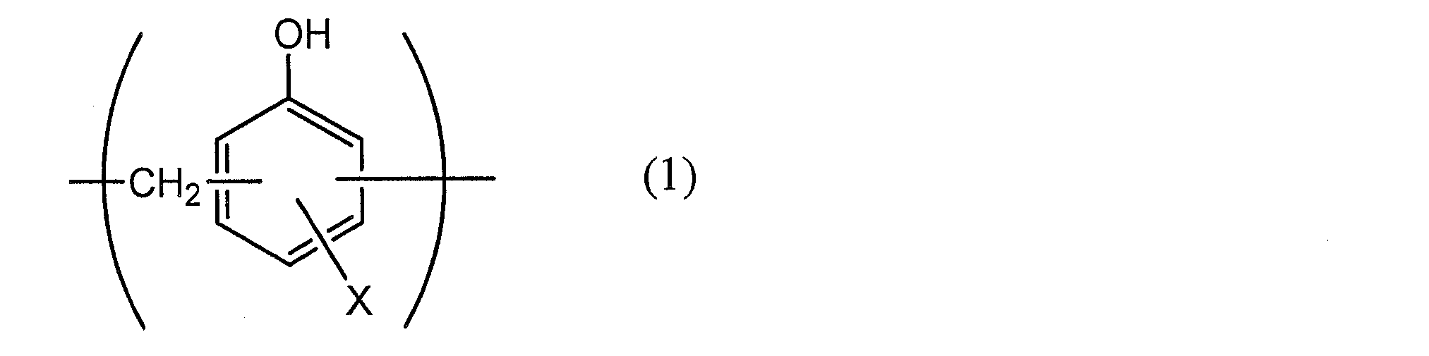


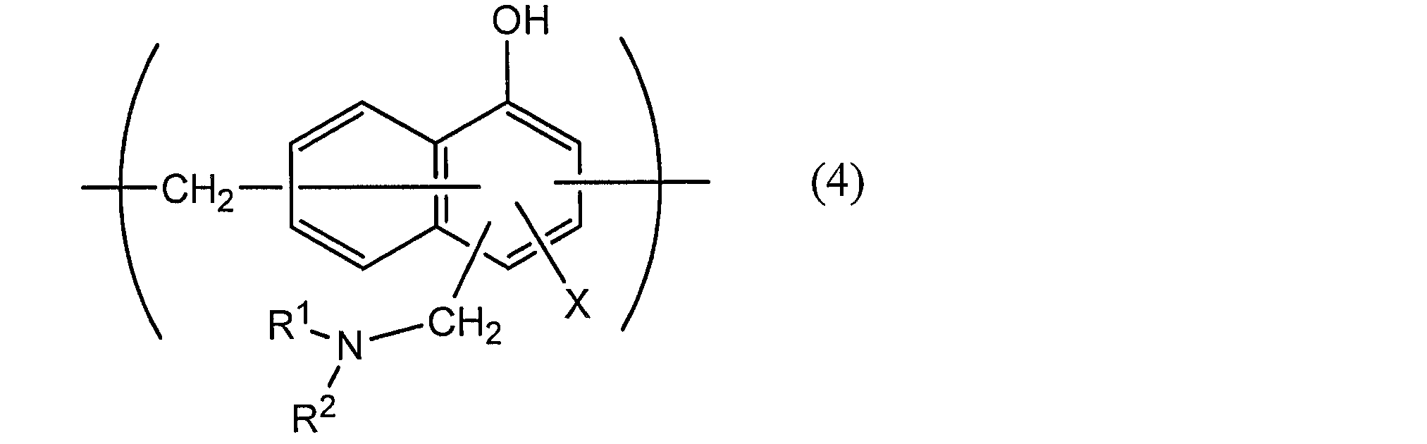
本開示の蓄電デバイス用外装材において、熱融着性樹脂層4は、最内層に該当し、蓄電デバイスの組み立て時に熱融着性樹脂層同士が熱融着して蓄電デバイス素子を密封する機能を発揮する層(シーラント層)である。
ポリオレフィンや、前記のポリオレフィンにアクリル酸若しくはメタクリル酸等の極性分子を共重合させた共重合体、又は、架橋ポリオレフィン等の重合体等も使用できる。また、酸変性に使用される酸成分としては、例えば、マレイン酸、アクリル酸、イタコン酸、クロトン酸、無水マレイン酸、無水イタコン酸等のカルボン酸またはその無水物が挙げられる。
本開示の蓄電デバイス用外装材において、接着層5は、バリア層3(又は耐酸性皮膜)と熱融着性樹脂層4を強固に接着させるために、これらの間に必要に応じて設けられる層である。
本開示の蓄電デバイス用外装材は、意匠性、耐電解液性、耐傷性、成形性などの向上の少なくとも一つを目的として、必要に応じて、基材層1の上(基材層1のバリア層3とは反対側)に、表面被覆層6を備えていてもよい。表面被覆層6は、蓄電デバイス用外装材を用いて蓄電デバイスを組み立てた時に、蓄電デバイス用外装材の最外層側に位置する層である。
蓄電デバイス用外装材の製造方法については、本開示の蓄電デバイス用外装材が備える各層を積層させた積層体が得られる限り、特に制限されず、少なくとも、基材層1、バリア層3、及び熱融着性樹脂4がこの順となるように積層する工程を備える方法が挙げられる。前記の通り、バリア層3としては、前述した所定の組成を満たすアルミニウム合金箔を用いることができる。
本開示の蓄電デバイス用外装材は、正極、負極、電解質等の蓄電デバイス素子を密封して収容するための包装体に使用される。すなわち、本開示の蓄電デバイス用外装材によって形成された包装体中に、少なくとも正極、負極、及び電解質を備えた蓄電デバイス素子を収容して、蓄電デバイスとすることができる。
<アルミニウム合金箔の製造>
表1に示す各組成(残部はAlおよびその他の不可避不純物)からなるアルミニウム合金の鋳塊を用意し、同表に示す条件で均質化処理を施した後、仕上がり温度330℃での熱間圧延にて厚さ3mmの板材とした。その後、冷間圧延、中間焼鈍、最終冷間圧延を経て、厚み40μm、幅1200mmのアルミニウム合金箔の試料を作製した。なお、中間焼鈍の方法については表1に示した。実施例8のCAL焼鈍は、昇温速度:40℃/秒、加熱温度:460℃、保持時間:1秒、冷却速度:40℃/秒の条件で行った。表1の冷間圧延の項目では、中間焼鈍直前の板厚および前記板厚までの冷間圧延率を示している。
引張強さ、伸びのいずれも引張試験にて測定した。引張試験は、JIS Z2241:2011(ISO 6892-1を基とする)に準拠し、圧延方向に対して0°方向の伸びを測定できるように、JIS5号試験片を試料から採取し、万能引張試験機(島津製作所社製 AGS-X 10kN)で引張り速度2mm/minにて試験を行った。伸び率の算出について以下の通りである。まず試験前に試験片長手中央に試験片垂直方向に2本の線を標点距離である50mm間隔でマークする。試験後にアルミニウム合金箔の破断面をつき合わせてマーク間距離を測定し、そこから標点距離(50mm)を引いた伸び量(mm)を、標点間距離(50mm)で除して伸び率(%)を求めた。なお、アルミニウム合金箔の伸びは、破断時の全伸び(伸び計の弾性伸びと塑性伸びとを合わせたもの)であり、伸び計標点距離に対する百分率で表したものである。
基材層としてポリエチレンテレフタレートフィルム(12μm)/接着剤層(2液硬化型ウレタン接着剤(ポリオール化合物と芳香族イソシアネート化合物)、厚さ3μm)/二軸延伸ナイロンフィルム(厚さ15μm)が順に積層された積層フィルムを用意した。次に、基材層の二軸延伸ナイロンフィルム(厚さ15μm)の上に、両面に耐酸性皮膜を形成した前記のアルミニウム合金箔(表1の組成を有し、厚さ40μm)からなるバリア層をドライラミネート法により積層させた。具体的には、両面に耐酸性皮膜(クロメート処理によって形成された皮膜であり、クロム量が30mg/m2)を形成したアルミニウム合金箔の一方面に、2液硬化型ウレタン接着剤(ポリオール化合物と芳香族イソシアネート化合物)を塗布し、アルミニウム合金箔上に接着剤層(硬化後の厚み3μm)を形成した。次いで、アルミニウム合金箔上の接着剤層と二軸延伸ナイロンフィルムを積層した後、エージング処理を実施することにより、基材層/接着剤層/バリア層の積層体を作製した。次に、得られた積層体のバリア層の上に、接着層としての無水マレイン酸変性ポリプロピレン(厚さ40μm)と、熱融着性樹脂層としてのポリプロピレン(厚さ40μm)とを共押出しすることにより、バリア層上に接着層/熱融着性樹脂層を積層させた。次に、得られた積層体をエージングし、加熱することにより、ポリエチレンテレフタレートフィルム(12μm)/接着剤層(3μm)/二軸延伸ナイロンフィルム(15μm)/接着剤層(3μm)/バリア層(40μm)/接着層(40μm)/熱融着性樹脂層(40μm)がこの順に積層された蓄電デバイス用外装材を得た。

上記で得られた各蓄電デバイス用外装材を長さ(MD)90mm×幅(TD)150mmの長方形に裁断して試験サンプルとした。蓄電デバイス用外装材のMDが、アルミニウム合金箔の圧延方向(RD)に対応し、蓄電デバイス用外装材のTDが、アルミニウム合金箔のTDに対応する。試験サンプルを25℃の環境下にて、31.6mm(MD)×54.5mm(TD)の矩形状の口径を有する成形金型(雌型、表面は、JIS B 0659-1:2002附属書1(参考) 比較用表面粗さ標準片の表2に規定される、最大高さ粗さ(Rzの呼び値)が3.2μmである。コーナーR2.0mm、稜線R1.0mm)と、これに対応した成形金型(雄型、表面は、JIS B 0659-1:2002附属書1(参考) 比較用表面粗さ標準片の表2に規定される、最大高さ粗さ(Rzの呼び値)が1.6μmである。コーナーR2.0mm、稜線R1.0mm)を用いて、押さえ圧(面圧)0.25MPaで0.5mmの成形深さから0.5mm単位で成形深さを変えて、それぞれ10個のサンプルについて冷間成形(引き込み1段成形)を行った。このとき、雄型側に熱融着性樹脂層側が位置するよう、雌型上に試験サンプルを載置して成形をおこなった。また、雄型及び雌型のクリアランスは、0.3mmとした。冷間成形後のサンプルについて、暗室の中にてペンライトで光を当てて、光の透過によって、アルミニウム合金箔にピンホールやクラックが生じているか否かを確認した。アルミニウム合金箔にピンホール、クラックが10個のサンプル全てにおいて発生しない最も深い成形深さを限界成形深さPmmとした。限界成形深さが4.0mm以上であった場合を評価A、3.0mm以下であった場合を評価Cとした。結果を表2に示す。
実施例1~20及び比較例1~8で使用した各アルミニウム合金箔を、長さ45mm×幅15mmの長方形に裁断した。次に、アルミニウム合金箔の表面及び裏面の一方の面に1cmφの露出部が形成されるように、アルミニウム合金箔の表面及び裏面に長さ50mm×幅20mmの長方形のポリエチレンフィルムをアルミニウム合金箔に重ねて熱溶着し取付け被覆して、試験サンプルとした。なお、試験サンプルにおける耐腐食性の評価は、アルミニウム合金箔ALが露出した1cmφの部分で行い、試験サンプルの電解液に浸漬されない端部については、作用極に接続するために露出させた。次に、図5の模式図に示すように、試験サンプルALを作用極、金属リチウムLi(直径15mm×厚み0.35mmの円盤状)を対極にセットし、電解液(1mol/lのLiPF6と、エチレンカーボネート、ジエチルカーボネート及びジメチルカーボネート(容量比1:1:1)の混合液とからなる)に浸漬させた。この状態で、20℃の環境下、電圧0.1Vで1時間印加した後、アルミニウム合金箔の表面を観察した。図8(比較例1)のように表面が腐食したものを評価C、図7(実施例1)のように変化しなかったものを評価Aとし、結果を表2に示す。腐食したアルミニウム合金箔表面はリチウムとの化合物が生成し、体積膨張により表面が盛り上がっている様子が観察される。
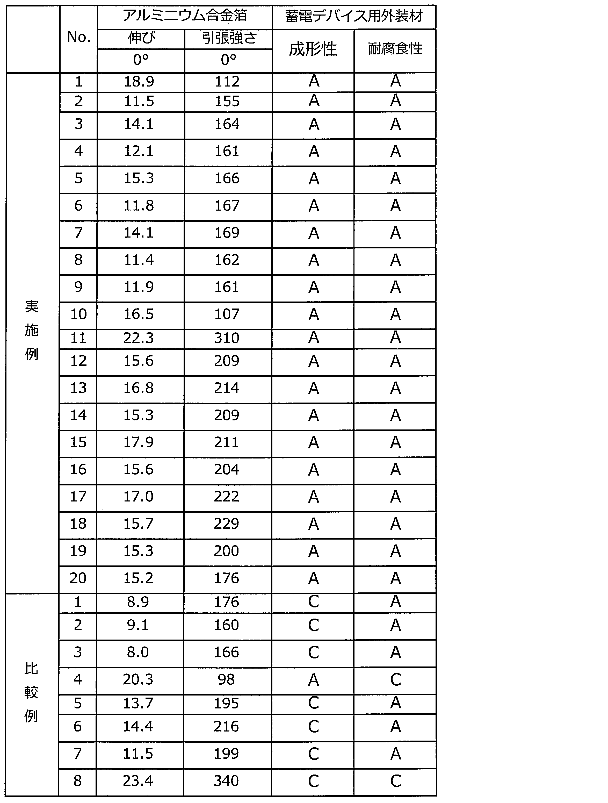
項1. 少なくとも、基材層、バリア層、及び熱融着性樹脂層をこの順に備える積層体から構成されており、
前記バリア層は、Si:0.5質量%以下、Fe:0.2質量%以上2.0質量%以下、Mg:0.1質量%以上5.0質量%以下の組成を満たすアルミニウム合金箔を含む、蓄電デバイス用外装材。
項2. 前記アルミニウム合金箔の組成は、Mn:0.1質量%以下を満たす、項1に記載の蓄電デバイス用外装材。
項3. 前記アルミニウム合金箔は、JIS Z2241:2011の規定に準拠して、JIS5号試験片について測定される、引張強さが100MPa以上であり、伸びが10%以上である、項1又は2に記載の蓄電デバイス用外装材。
項4. 少なくとも正極、負極、及び電解質を備えた蓄電デバイス素子が、項1~3のいずれか1項に記載の蓄電デバイス用外装材により形成された包装体中に収容されている、蓄電デバイス。
項5. 少なくとも、基材層、バリア層、及び熱融着性樹脂層がこの順となるように積層して積層体を得る工程を備えており、
前記バリア層は、Si:0.5質量%以下、Fe:0.2質量%以上2.0質量%以下、Mg:0.1質量%以上5.0質量%以下の組成を満たすアルミニウム合金箔を含む、蓄電デバイス用外装材の製造方法。
2 接着剤層
3 バリア層
4 熱融着性樹脂層
5 接着層
6 表面被覆層
10 蓄電デバイス用外装材
Claims (5)
- 少なくとも、基材層、バリア層、及び熱融着性樹脂層をこの順に備える積層体から構成されており、
前記バリア層は、Si:0.5質量%以下、Fe:0.2質量%以上2.0質量%以下、Mg:0.1質量%以上5.0質量%以下の組成を満たすアルミニウム合金箔を含む、蓄電デバイス用外装材。 - 前記アルミニウム合金箔の組成は、Mn:0.1質量%以下を満たす、請求項1に記載の蓄電デバイス用外装材。
- 前記アルミニウム合金箔は、JIS Z2241:2011の規定に準拠して、JIS5号試験片について測定される、引張強さが100MPa以上であり、伸びが10%以上である、請求項1又は2に記載の蓄電デバイス用外装材。
- 少なくとも正極、負極、及び電解質を備えた蓄電デバイス素子が、請求項1~3のいずれか1項に記載の蓄電デバイス用外装材により形成された包装体中に収容されている、蓄電デバイス。
- 少なくとも、基材層、バリア層、及び熱融着性樹脂層がこの順となるように積層して積層体を得る工程を備えており、
前記バリア層は、Si:0.5質量%以下、Fe:0.2質量%以上2.0質量%以下、Mg:0.1質量%以上5.0質量%以下の組成を満たすアルミニウム合金箔を含む、蓄電デバイス用外装材の製造方法。
Priority Applications (7)
| Application Number | Priority Date | Filing Date | Title |
|---|---|---|---|
| KR1020257012279A KR20250057922A (ko) | 2019-12-25 | 2020-12-25 | 축전 디바이스용 외장재, 그 제조 방법, 및 축전 디바이스 |
| US17/788,574 US20220375697A1 (en) | 2019-12-25 | 2020-12-25 | Exterior material for electrical storage device, method for manufacturing same, and electrical storage device |
| CN202080089718.6A CN114902472A (zh) | 2019-12-25 | 2020-12-25 | 蓄电装置用外包装材料、其制造方法和蓄电装置 |
| JP2021567670A JP7160217B2 (ja) | 2019-12-25 | 2020-12-25 | 蓄電デバイス用外装材、その製造方法、及び蓄電デバイス |
| KR1020227018128A KR102798122B1 (ko) | 2019-12-25 | 2020-12-25 | 축전 디바이스용 외장재, 그 제조 방법, 및 축전 디바이스 |
| EP20907511.8A EP4084029A4 (en) | 2019-12-25 | 2020-12-25 | EXTERIOR MATERIAL FOR ELECTRIC STORAGE DEVICE, MANUFACTURING METHOD THEREOF, AND ELECTRIC STORAGE DEVICE |
| JP2022162925A JP2023011625A (ja) | 2019-12-25 | 2022-10-11 | 蓄電デバイス用外装材、その製造方法、及び蓄電デバイス |
Applications Claiming Priority (2)
| Application Number | Priority Date | Filing Date | Title |
|---|---|---|---|
| JP2019234058 | 2019-12-25 | ||
| JP2019-234058 | 2019-12-25 |
Publications (1)
| Publication Number | Publication Date |
|---|---|
| WO2021132562A1 true WO2021132562A1 (ja) | 2021-07-01 |
Family
ID=76575563
Family Applications (1)
| Application Number | Title | Priority Date | Filing Date |
|---|---|---|---|
| PCT/JP2020/048733 Ceased WO2021132562A1 (ja) | 2019-12-25 | 2020-12-25 | 蓄電デバイス用外装材、その製造方法、及び蓄電デバイス |
Country Status (6)
| Country | Link |
|---|---|
| US (1) | US20220375697A1 (ja) |
| EP (1) | EP4084029A4 (ja) |
| JP (2) | JP7160217B2 (ja) |
| KR (2) | KR20250057922A (ja) |
| CN (1) | CN114902472A (ja) |
| WO (1) | WO2021132562A1 (ja) |
Families Citing this family (4)
| Publication number | Priority date | Publication date | Assignee | Title |
|---|---|---|---|---|
| JP7192451B2 (ja) | 2018-01-25 | 2022-12-20 | 三菱マテリアル株式会社 | 銅/セラミックス接合体、絶縁回路基板、及び、銅/セラミックス接合体の製造方法、絶縁回路基板の製造方法 |
| WO2020044590A1 (ja) * | 2018-08-28 | 2020-03-05 | 三菱マテリアル株式会社 | 銅/セラミックス接合体、絶縁回路基板、及び、銅/セラミックス接合体の製造方法、及び、絶縁回路基板の製造方法 |
| CN111653694B (zh) * | 2020-05-21 | 2021-08-06 | 上海恩捷新材料科技有限公司 | 一种电池装置用外包装材料及电池 |
| CN121942082A (zh) * | 2023-10-10 | 2026-04-28 | 株式会社Lg新能源 | 袋型电池盒以及包括袋型电池盒的锂二次电池、电池模块和电池组 |
Citations (9)
| Publication number | Priority date | Publication date | Assignee | Title |
|---|---|---|---|---|
| JPS61110744A (ja) * | 1984-11-02 | 1986-05-29 | Kobe Steel Ltd | 包装用a1合金板及びその製造方法 |
| JPH11195404A (ja) * | 1997-12-26 | 1999-07-21 | Sanyo Electric Co Ltd | 薄型電池 |
| JP2005163077A (ja) | 2003-12-01 | 2005-06-23 | Mitsubishi Alum Co Ltd | 包装材用高成形性アルミニウム箔及びその製造方法 |
| JP2005343105A (ja) * | 2004-06-07 | 2005-12-15 | Sumitomo Light Metal Ind Ltd | アルミニウムラミネート材 |
| JP2007073402A (ja) * | 2005-09-08 | 2007-03-22 | Sumitomo Light Metal Ind Ltd | 電池外装用アルミラミネート構成物 |
| JP2008287971A (ja) | 2007-05-16 | 2008-11-27 | Sony Corp | 積層型包装材料、電池用外装部材および電池 |
| JP2015165476A (ja) * | 2014-03-03 | 2015-09-17 | 大日本印刷株式会社 | 電池用包装材料 |
| WO2017188396A1 (ja) * | 2016-04-27 | 2017-11-02 | 大日本印刷株式会社 | 電池用包装材料、その製造方法、電池及びその製造方法 |
| JP2018168449A (ja) * | 2017-03-30 | 2018-11-01 | 株式会社Uacj | アルミニウム合金軟質箔およびその製造方法並びに二次電池用外装材 |
Family Cites Families (6)
| Publication number | Priority date | Publication date | Assignee | Title |
|---|---|---|---|---|
| JP5220310B2 (ja) * | 2006-12-26 | 2013-06-26 | 日本軽金属株式会社 | 自動車用アルミニウム合金板及びその製造方法 |
| US20150140397A1 (en) * | 2013-11-15 | 2015-05-21 | Semiconductor Energy Laboratory Co., Ltd. | Multilayer film, exterior material for secondary battery, secondary battery, and electronic device |
| EP3352548B1 (en) * | 2015-09-18 | 2020-10-28 | Toray Industries, Inc. | Electronic device housing |
| KR20190018741A (ko) * | 2016-08-05 | 2019-02-25 | 다이니폰 인사츠 가부시키가이샤 | 전지용 포장 재료 및 전지 |
| CN110476288B (zh) * | 2017-02-24 | 2022-11-04 | 株式会社杰士汤浅国际 | 非水电解质蓄电元件及其制造方法 |
| JP7205547B2 (ja) * | 2018-10-24 | 2023-01-17 | 大日本印刷株式会社 | アルミニウム合金箔、蓄電デバイス用外装材、その製造方法、及び蓄電デバイス |
-
2020
- 2020-12-25 EP EP20907511.8A patent/EP4084029A4/en active Pending
- 2020-12-25 US US17/788,574 patent/US20220375697A1/en active Pending
- 2020-12-25 KR KR1020257012279A patent/KR20250057922A/ko active Pending
- 2020-12-25 CN CN202080089718.6A patent/CN114902472A/zh active Pending
- 2020-12-25 WO PCT/JP2020/048733 patent/WO2021132562A1/ja not_active Ceased
- 2020-12-25 KR KR1020227018128A patent/KR102798122B1/ko active Active
- 2020-12-25 JP JP2021567670A patent/JP7160217B2/ja active Active
-
2022
- 2022-10-11 JP JP2022162925A patent/JP2023011625A/ja active Pending
Patent Citations (9)
| Publication number | Priority date | Publication date | Assignee | Title |
|---|---|---|---|---|
| JPS61110744A (ja) * | 1984-11-02 | 1986-05-29 | Kobe Steel Ltd | 包装用a1合金板及びその製造方法 |
| JPH11195404A (ja) * | 1997-12-26 | 1999-07-21 | Sanyo Electric Co Ltd | 薄型電池 |
| JP2005163077A (ja) | 2003-12-01 | 2005-06-23 | Mitsubishi Alum Co Ltd | 包装材用高成形性アルミニウム箔及びその製造方法 |
| JP2005343105A (ja) * | 2004-06-07 | 2005-12-15 | Sumitomo Light Metal Ind Ltd | アルミニウムラミネート材 |
| JP2007073402A (ja) * | 2005-09-08 | 2007-03-22 | Sumitomo Light Metal Ind Ltd | 電池外装用アルミラミネート構成物 |
| JP2008287971A (ja) | 2007-05-16 | 2008-11-27 | Sony Corp | 積層型包装材料、電池用外装部材および電池 |
| JP2015165476A (ja) * | 2014-03-03 | 2015-09-17 | 大日本印刷株式会社 | 電池用包装材料 |
| WO2017188396A1 (ja) * | 2016-04-27 | 2017-11-02 | 大日本印刷株式会社 | 電池用包装材料、その製造方法、電池及びその製造方法 |
| JP2018168449A (ja) * | 2017-03-30 | 2018-11-01 | 株式会社Uacj | アルミニウム合金軟質箔およびその製造方法並びに二次電池用外装材 |
Non-Patent Citations (1)
| Title |
|---|
| See also references of EP4084029A4 |
Also Published As
| Publication number | Publication date |
|---|---|
| JP2023011625A (ja) | 2023-01-24 |
| JP7160217B2 (ja) | 2022-10-25 |
| KR102798122B1 (ko) | 2025-04-18 |
| EP4084029A1 (en) | 2022-11-02 |
| KR20220122979A (ko) | 2022-09-05 |
| US20220375697A1 (en) | 2022-11-24 |
| EP4084029A4 (en) | 2024-09-18 |
| CN114902472A (zh) | 2022-08-12 |
| KR20250057922A (ko) | 2025-04-29 |
| JPWO2021132562A1 (ja) | 2021-07-01 |
Similar Documents
| Publication | Publication Date | Title |
|---|---|---|
| JP7731341B2 (ja) | アルミニウム合金箔、蓄電デバイス用外装材、その製造方法、及び蓄電デバイス | |
| JP7104136B2 (ja) | 蓄電デバイス用外装材、その製造方法、及び蓄電デバイス | |
| JP7160217B2 (ja) | 蓄電デバイス用外装材、その製造方法、及び蓄電デバイス | |
| JPWO2020071254A1 (ja) | 蓄電デバイス用外装材、その製造方法、及び蓄電デバイス | |
| JP7104137B2 (ja) | 蓄電デバイス用外装材、その製造方法、及び蓄電デバイス | |
| JP6828858B1 (ja) | 蓄電デバイス用外装材、その製造方法、及び蓄電デバイス | |
| JP7036295B2 (ja) | 蓄電デバイス用外装材、その製造方法、及び蓄電デバイス | |
| JPWO2020085462A1 (ja) | 蓄電デバイス用外装材、その製造方法、及び蓄電デバイス | |
| JP7276632B1 (ja) | 蓄電デバイス用外装材、その製造方法、及び蓄電デバイス | |
| EP4366045A1 (en) | Power storage device and method for manufacturing power storage device | |
| JP6989071B1 (ja) | 蓄電デバイス用外装材、その製造方法、及び蓄電デバイス | |
| JP7239083B1 (ja) | 蓄電デバイス用外装材、その製造方法、及び蓄電デバイス | |
| JP7746709B2 (ja) | 蓄電デバイス用外装材、その製造方法、及び蓄電デバイス | |
| JPWO2020085461A1 (ja) | 蓄電デバイス用外装材、その製造方法、及び蓄電デバイス | |
| JP6769142B2 (ja) | 電池用包装材料、その製造方法及び電池 | |
| WO2026071266A1 (ja) | 蓄電デバイス、その製造方法、及び蓄電デバイス用外装材 | |
| WO2026070700A1 (ja) | 蓄電デバイス用外装材、その製造方法、及び蓄電デバイス | |
| WO2026071265A1 (ja) | 蓄電デバイス用外装材、その製造方法、及び蓄電デバイス | |
| JP2022078059A (ja) | 蓄電デバイス用外装材、その製造方法、及び蓄電デバイス | |
| WO2022114024A1 (ja) | 蓄電デバイス用外装材、その製造方法、及び蓄電デバイス |
Legal Events
| Date | Code | Title | Description |
|---|---|---|---|
| 121 | Ep: the epo has been informed by wipo that ep was designated in this application |
Ref document number: 20907511 Country of ref document: EP Kind code of ref document: A1 |
|
| ENP | Entry into the national phase |
Ref document number: 2021567670 Country of ref document: JP Kind code of ref document: A |
|
| NENP | Non-entry into the national phase |
Ref country code: DE |
|
| ENP | Entry into the national phase |
Ref document number: 2020907511 Country of ref document: EP Effective date: 20220725 |
|
| WWD | Wipo information: divisional of initial pct application |
Ref document number: 1020257012279 Country of ref document: KR |
|
| WWP | Wipo information: published in national office |
Ref document number: 1020257012279 Country of ref document: KR |