WO2021144959A1 - 超音波霧化装置 - Google Patents
超音波霧化装置 Download PDFInfo
- Publication number
- WO2021144959A1 WO2021144959A1 PCT/JP2020/001494 JP2020001494W WO2021144959A1 WO 2021144959 A1 WO2021144959 A1 WO 2021144959A1 JP 2020001494 W JP2020001494 W JP 2020001494W WO 2021144959 A1 WO2021144959 A1 WO 2021144959A1
- Authority
- WO
- WIPO (PCT)
- Prior art keywords
- ultrasonic
- cup
- thin film
- separator cup
- separator
- Prior art date
- Legal status (The legal status is an assumption and is not a legal conclusion. Google has not performed a legal analysis and makes no representation as to the accuracy of the status listed.)
- Ceased
Links
Images




Classifications
-
- B—PERFORMING OPERATIONS; TRANSPORTING
- B05—SPRAYING OR ATOMISING IN GENERAL; APPLYING FLUENT MATERIALS TO SURFACES, IN GENERAL
- B05B—SPRAYING APPARATUS; ATOMISING APPARATUS; NOZZLES
- B05B17/00—Apparatus for spraying or atomising liquids or other fluent materials, not covered by the preceding groups
- B05B17/04—Apparatus for spraying or atomising liquids or other fluent materials, not covered by the preceding groups operating with special methods
- B05B17/06—Apparatus for spraying or atomising liquids or other fluent materials, not covered by the preceding groups operating with special methods using ultrasonic or other kinds of vibrations
- B05B17/0607—Apparatus for spraying or atomising liquids or other fluent materials, not covered by the preceding groups operating with special methods using ultrasonic or other kinds of vibrations generated by electrical means, e.g. piezoelectric transducers
-
- B—PERFORMING OPERATIONS; TRANSPORTING
- B05—SPRAYING OR ATOMISING IN GENERAL; APPLYING FLUENT MATERIALS TO SURFACES, IN GENERAL
- B05B—SPRAYING APPARATUS; ATOMISING APPARATUS; NOZZLES
- B05B17/00—Apparatus for spraying or atomising liquids or other fluent materials, not covered by the preceding groups
- B05B17/04—Apparatus for spraying or atomising liquids or other fluent materials, not covered by the preceding groups operating with special methods
- B05B17/06—Apparatus for spraying or atomising liquids or other fluent materials, not covered by the preceding groups operating with special methods using ultrasonic or other kinds of vibrations
- B05B17/0607—Apparatus for spraying or atomising liquids or other fluent materials, not covered by the preceding groups operating with special methods using ultrasonic or other kinds of vibrations generated by electrical means, e.g. piezoelectric transducers
- B05B17/0615—Apparatus for spraying or atomising liquids or other fluent materials, not covered by the preceding groups operating with special methods using ultrasonic or other kinds of vibrations generated by electrical means, e.g. piezoelectric transducers spray being produced at the free surface of the liquid or other fluent material in a container and subjected to the vibrations
-
- B—PERFORMING OPERATIONS; TRANSPORTING
- B05—SPRAYING OR ATOMISING IN GENERAL; APPLYING FLUENT MATERIALS TO SURFACES, IN GENERAL
- B05B—SPRAYING APPARATUS; ATOMISING APPARATUS; NOZZLES
- B05B7/00—Spraying apparatus for discharge of liquids or other fluent materials from two or more sources, e.g. of liquid and air, of powder and gas
- B05B7/0012—Apparatus for achieving spraying before discharge from the apparatus
-
- B—PERFORMING OPERATIONS; TRANSPORTING
- B05—SPRAYING OR ATOMISING IN GENERAL; APPLYING FLUENT MATERIALS TO SURFACES, IN GENERAL
- B05B—SPRAYING APPARATUS; ATOMISING APPARATUS; NOZZLES
- B05B7/00—Spraying apparatus for discharge of liquids or other fluent materials from two or more sources, e.g. of liquid and air, of powder and gas
- B05B7/24—Spraying apparatus for discharge of liquids or other fluent materials from two or more sources, e.g. of liquid and air, of powder and gas with means, e.g. a container, for supplying liquid or other fluent material to a discharge device
- B05B7/2489—Spraying apparatus for discharge of liquids or other fluent materials from two or more sources, e.g. of liquid and air, of powder and gas with means, e.g. a container, for supplying liquid or other fluent material to a discharge device an atomising fluid, e.g. a gas, being supplied to the discharge device
- B05B7/2491—Spraying apparatus for discharge of liquids or other fluent materials from two or more sources, e.g. of liquid and air, of powder and gas with means, e.g. a container, for supplying liquid or other fluent material to a discharge device an atomising fluid, e.g. a gas, being supplied to the discharge device characterised by the means for producing or supplying the atomising fluid, e.g. air hoses, air pumps, gas containers, compressors, fans, ventilators, their drives
-
- B—PERFORMING OPERATIONS; TRANSPORTING
- B05—SPRAYING OR ATOMISING IN GENERAL; APPLYING FLUENT MATERIALS TO SURFACES, IN GENERAL
- B05B—SPRAYING APPARATUS; ATOMISING APPARATUS; NOZZLES
- B05B17/00—Apparatus for spraying or atomising liquids or other fluent materials, not covered by the preceding groups
- B05B17/04—Apparatus for spraying or atomising liquids or other fluent materials, not covered by the preceding groups operating with special methods
- B05B17/06—Apparatus for spraying or atomising liquids or other fluent materials, not covered by the preceding groups operating with special methods using ultrasonic or other kinds of vibrations
- B05B17/0607—Apparatus for spraying or atomising liquids or other fluent materials, not covered by the preceding groups operating with special methods using ultrasonic or other kinds of vibrations generated by electrical means, e.g. piezoelectric transducers
- B05B17/0653—Details
-
- B—PERFORMING OPERATIONS; TRANSPORTING
- B05—SPRAYING OR ATOMISING IN GENERAL; APPLYING FLUENT MATERIALS TO SURFACES, IN GENERAL
- B05B—SPRAYING APPARATUS; ATOMISING APPARATUS; NOZZLES
- B05B17/00—Apparatus for spraying or atomising liquids or other fluent materials, not covered by the preceding groups
- B05B17/04—Apparatus for spraying or atomising liquids or other fluent materials, not covered by the preceding groups operating with special methods
- B05B17/06—Apparatus for spraying or atomising liquids or other fluent materials, not covered by the preceding groups operating with special methods using ultrasonic or other kinds of vibrations
- B05B17/0607—Apparatus for spraying or atomising liquids or other fluent materials, not covered by the preceding groups operating with special methods using ultrasonic or other kinds of vibrations generated by electrical means, e.g. piezoelectric transducers
- B05B17/0653—Details
- B05B17/0669—Excitation frequencies
Definitions
- the present invention relates to an ultrasonic atomizer that atomizes (mists) a raw material solution into fine mist using an ultrasonic vibrator and conveys the mist to the outside.
- An ultrasonic atomizer may be used at the site of manufacturing electronic devices.
- the ultrasonic atomizer uses ultrasonic waves oscillated from an ultrasonic vibrator to mist a solution, and sends the mistized solution to the outside by a transport gas.
- a transport gas By spraying the raw material solution mist conveyed to the outside onto the substrate, a thin film for an electronic device is formed on the substrate.
- a double chamber method in which the raw material solution and the ultrasonic vibrator do not come into contact with each other.
- a separator cup for accommodating the raw material solution is used in addition to the water tank provided with the ultrasonic vibrator on the bottom surface in order to separate the ultrasonic vibrator and the raw material solution.
- the separator cup needs to transmit ultrasonic waves, and a material such as polyethylene or polypropylene (PP) that easily transmits ultrasonic waves is used as a constituent material.
- PP polyethylene and polypropylene
- polyethylene and polypropylene also have the characteristic of being easy to mold.
- a highly soluble solvent such as toluene or ether is used as the solvent for the raw material solution. This is because toluene and ether have a high resin solubility property.
- the resin solubility of the solvent is high, so that the separator cup made of polyethylene or polypropylene swells and deforms to form the raw material.
- the solution may leak or the separator cup may be punctured.
- the conventional ultrasonic atomizer has a problem that the storage stability of the raw material solution is deteriorated, so that the raw material solution mist with an appropriate amount of atomization cannot be generated.
- An object of the present invention is to provide an ultrasonic atomizer that solves the above-mentioned problems, has excellent resistance to a raw material solution, and can generate a raw material solution mist having an appropriate amount of atomization. do.
- the ultrasonic atomizer in the present invention has a container having a separator cup for accommodating a raw material solution at the bottom, an internal hollow structure provided above the separator cup in the container and having a hollow inside, and an ultrasonic atomizer inside.
- a water tank for accommodating a sound wave transmission medium is provided, and the water tank and the separator cup are positioned so that the bottom surface of the separator cup is immersed in the ultrasonic wave transmission medium, and at least one ultrasonic vibration provided on the bottom surface of the water tank.
- the separator cup is further provided with a child, and the separator cup is characterized in that the constituent material is a fluororesin and the thickness has a bottom surface satisfying the thin film condition, and the thin film condition is "the thickness of the bottom surface is 0.5 mm or less". do.
- the constituent material of the bottom surface of the separator cup in the ultrasonic atomizer of the present invention according to claim 1 is fluororesin. Fluororesin has the property of having relatively high resistance to a wide range of solvents. Therefore, the separator cup of the ultrasonic atomizer can exhibit relatively high resistance to the raw material solution.
- the separator cup of the present invention according to claim 1 is suitable because it enhances the transparency of ultrasonic waves on the bottom surface by satisfying the thin film condition that "the thickness of the bottom surface is 0.5 mm or less".
- the raw material solution mist can be generated by the amount of atomization.
- the invention of the present application according to claim 1 has an effect of being excellent in resistance to the raw material solution and being able to generate a raw material solution mist having an appropriate atomization amount.
- FIG. 1 shows the initial state (No. 1)
- FIG. 2 shows the time when the raw material solution mist MT is generated (No. 2).
- the ultrasonic atomizer 101 includes a container 1, an ultrasonic vibrator 2 which is a mist atomizer, an internal cavity structure 3, and a gas supply unit 4. Further, as shown in FIGS. 1 and 2, the container 1 has a structure in which the upper cup 11 and the separator cup 12 are connected by the connecting portion 5.
- the upper cup 11 may have any shape as long as it is a container in which a space is formed.
- the upper cup 11 has a substantially cylindrical shape, and a space surrounded by side surfaces formed in a circular shape in a plan view is formed in the upper cup 11.
- the raw material solution 15 is housed in the separator cup 12.
- the constituent material of the separator cup 12 is PTFE (PolyTetraFluoroEthylene), which is one of the fluororesins, and has a uniform overall thickness of 0.5 mm. That is, the separator cup 12 has a bottom surface BP1 having a thickness of 0.5 mm and a constituent material of PTFE.
- the separator cup 12 of the first embodiment is characterized in that it satisfies the thin film condition that "the thickness of the bottom surface BP1 is 0.5 mm or less".
- the ultrasonic vibrator 2 mistizes (atomizes) the raw material solution 15 by applying ultrasonic waves to the raw material solution 15 in the separator cup 12.
- the four ultrasonic transducers 2 (only two are shown in FIGS. 1 and 2) are arranged on the bottom surface of the water tank 10.
- the number of ultrasonic vibrators 2 is not limited to four, and may be one or two or more.
- the internal cavity structure 3 is a structure having a cavity inside. An opening is formed in the upper surface of the upper cup 11 of the container 1, and as shown in FIGS. 1 and 2, the internal cavity structure 3 is inserted into the upper cup 11 through the opening. It is arranged so as to be. Here, in a state where the internal cavity structure 3 is inserted through the opening, the internal cavity structure 3 and the upper cup 11 are sealed. That is, the internal cavity structure 3 and the opening of the upper cup 11 are sealed.
- the shape of the internal cavity structure 3 may be any shape as long as the cavity is formed inside.
- the internal cavity structure 3 has a flask-shaped cross-sectional shape having no bottom surface. More specifically, the internal cavity structure 3 shown in FIG. 1 is composed of a pipe portion 3A, a truncated cone portion 3B, and a cylindrical portion 3C.
- the pipe portion 3A is a cylindrical conduit portion, and the pipe portion 3A extends from the outside of the upper cup 11 to the inside of the upper cup 11 so as to be inserted through an opening provided on the upper surface of the upper cup 11.
- the pipe portion 3A is divided into an upper pipe portion arranged outside the upper cup 11 and a lower pipe portion arranged inside the upper cup 11. Then, the upper pipe portion is attached from the outside of the upper surface of the upper cup 11, the lower pipe portion is attached from the inside of the upper surface of the upper cup 11, and in a state where these are attached, the upper pipe portion and the lower pipe portion are upper. It communicates through an opening provided on the upper surface of the cup 11.
- One end of the tube portion 3A is connected to the outside of the upper cup 11, for example, into a thin film forming apparatus for forming a thin film using a raw material solution mist MT.
- the other end of the pipe portion 3A is connected to the upper end side of the truncated cone portion 3B in the upper cup 11.
- the truncated cone portion 3B has a truncated cone shape in appearance (side wall surface), and a cavity is formed inside.
- the top and bottom surfaces of the truncated cone portion 3B are open. That is, the cavity formed inside is closed, and there is no upper surface or bottom surface.
- the truncated cone portion 3B exists in the upper cup 11, and the upper end side of the truncated cone portion 3B is connected (communicated) with the other end of the tubular portion 3A as described above.
- the lower end side is connected to the upper end side of the cylindrical portion 3C.
- the truncated cone portion 3B has a cross-sectional shape that widens toward the lower end side from the upper end side. That is, the diameter of the side wall on the upper end side of the truncated cone portion 3B is the smallest (same as the diameter of the pipe portion 3A), and the diameter of the side wall on the lower end side of the truncated cone portion 3B is the largest (same as the diameter of the cylindrical portion 3C).
- the diameter of the side wall of the truncated cone portion 3B smoothly increases from the upper end side to the lower end side.
- the cylindrical portion 3C is a portion having a cylindrical shape, and the upper end side of the cylindrical portion 3C is connected (communicated) with the lower end side of the truncated cone portion 3B as described above, and the lower end side of the cylindrical portion 3C is It faces the bottom surface of the upper cup 11.
- the lower end side of the cylindrical portion 3C is open (that is, it does not have a bottom surface).
- the central axis of the internal cavity structure 3 in the direction extending from the pipe portion 3A through the truncated cone portion 3B to the cylindrical portion 3C is the center of the cylindrical shape of the upper cup 11. It is almost the same as the axis. Even if the internal cavity structure 3 has an integral structure, as shown in FIGS. 1 and 2, the upper pipe portion forming a part of the pipe portion 3A and the lower pipe portion forming the other part of the pipe portion 3A are formed. , Each member of the truncated cone portion 3B and the cylindrical portion 3C may be combined and configured. In the configuration example of FIG.
- the lower end of the upper pipe portion is connected to the outer upper surface of the upper cup 11
- the upper end portion of the lower pipe portion is connected to the inner upper surface of the upper cup 11
- the lower end portion of the lower pipe portion is connected.
- the first space is a cavity formed inside the internal cavity structure 3.
- this cavity is referred to as "mistized space 3H".
- the mistized space 3H is a space surrounded by the inner side surface of the internal cavity structure 3.
- the second space is a space formed by the inner surface of the upper cup 11 and the outer surface of the inner cavity structure 3.
- this space is referred to as "gas supply space 1H".
- the inside of the upper cup 11 is divided into a mist-forming space 3H and a gas supply space 1H.
- mist-forming space 3H and the gas supply space 1H are connected to each other through the lower opening of the cylindrical portion 3C.
- the gas supply space 1H is widest on the upper side of the upper cup 11, and the upper cup 11 It gets narrower as you go down. That is, the gas supply space 1H of the portion surrounded by the outer surface of the pipe portion 3A and the inner surface of the upper cup 11 is the widest, and the gas supply of the portion surrounded by the outer surface of the cylindrical portion 3C and the inner surface of the upper cup 11 Space 1H is the narrowest.
- the gas supply unit 4 is arranged on the upper surface of the upper cup 11.
- the carrier gas G4 for transporting the raw material solution mist MT (see FIG. 2) misted by the ultrasonic vibrator 2 from the gas supply unit 4 to the outside through the pipe portion 3A of the internal cavity structure 3. Is supplied.
- the carrier gas G4 for example, a high-concentration inert gas can be adopted.
- the gas supply unit 4 is provided with a supply port 4a, and the carrier gas G4 is provided in the gas supply space 1H of the container 1 from the supply port 4a existing in the container 1. Is supplied to.
- the carrier gas G4 supplied from the gas supply unit 4 is supplied into the gas supply space 1H, fills the gas supply space 1H, and then enters the mistized space 3H through the lower opening of the cylindrical portion 3C. be introduced.
- the separator cup 12 of the container 1 has a cup shape and contains the raw material solution 15 inside.
- the bottom surface BP1 of the separator cup 12 is gently inclined from the side surface toward the center, and is formed in a spherical shape having a predetermined curvature.
- the water tank 10 is filled with ultrasonic wave transmission water 9 which is an ultrasonic wave transmission medium.
- the ultrasonic transmission water 9 has a function of transmitting ultrasonic vibration generated from the ultrasonic vibrator 2 arranged on the bottom surface of the water tank 10 to the raw material solution 15 in the separator cup 12.
- the ultrasonic transmission water 9 is housed in the water tank 10 so that the vibration energy of the ultrasonic waves applied from the ultrasonic transducer 2 can be transmitted into the separator cup 12.
- the bottom surface BP1 of the separator cup 12 contains the raw material solution 15 to be mistized, and the liquid level 15A of the raw material solution 15 is located below the arrangement position of the connection portion 5. (See FIGS. 1 and 2).
- the separator cup 12 and the water tank 10 are positioned and set so that the entire bottom surface BP1 of the separator cup 12 is immersed in the ultrasonic transmission water 9. That is, the bottom surface BP1 of the separator cup 12 is arranged above the bottom surface of the water tank 10 without touching the bottom surface of the water tank 10, and the ultrasonic transmission water 9 is provided between the bottom surface BP1 of the separator cup 12 and the bottom surface of the water tank 10. Exists.
- the vibration energy of the ultrasonic waves is transmitted through the ultrasonic transmission water 9 and the bottom surface BP1 of the separator cup 12 to the separator cup. It is transmitted to the raw material solution 15 in 12.
- the liquid column 6 rises from the liquid level 15A, the raw material solution 15 moves into liquid particles and mist, and the raw material solution mist MT is obtained in the mist-forming space 3H.
- the raw material solution mist MT generated in the gas supply space 1H is supplied to the outside by the carrier gas G4 supplied from the gas supply unit 4 through the upper opening of the pipe portion 3A.
- FIG. 6 and 7 are explanatory views schematically showing the configuration of the conventional ultrasonic atomizer 200, respectively.
- FIG. 6 shows the initial state (No. 1)
- FIG. 7 shows the time when the raw material solution mist MT is generated (No. 2).
- the container 51 corresponding to the container 1 of the ultrasonic atomizer 101 is composed of a combined structure of an upper cup 61 and a separator cup 62.
- the upper cup 61 is configured in the same manner as the upper cup 11.
- the conventional separator cup 62 corresponding to the separator cup 12 of the first embodiment adopts polypropylene (PP) which easily transmits ultrasonic waves as a constituent material, and has a uniform overall thickness of 1.0 mm. ..
- the thickness of the separator cup 62 is increased so that the thickness of the separator cup 62 is kept as thin as possible to maintain the transparency of ultrasonic waves (suppressing the attenuation of vibration energy due to ultrasonic waves) and to maintain the shape of the separator cup 62. It is set to 1.0 mm.
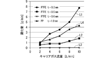
- FIG. 3 is a graph showing the effect of the first embodiment.
- the flow rate [L / min] of the carrier gas G4 is shown on the horizontal axis
- the atomization amount [g / min] of the generated raw material solution mist MT is shown on the vertical axis.
- distilled water at 34 ° C. is used as the raw material solution 15, and four ultrasonic vibrators 2 of TDK model NB-59S-09S-0 are arranged on the bottom surface of the water tank 10, and four ultrasonic vibrations are generated.
- the result of the experiment performed by setting the vibration frequency of the child 2 to 1.6 MHz is shown.
- Nitrogen gas is used as the carrier gas G4.
- the atomization amount change L1 shows the case where the constituent material of the separator cup 12 is PTFE and the film thickness t of the bottom surface BP1 is 0.3 mm.
- the atomization amount change L2 shows a case where the constituent material of the separator cup 12 is PTFE and the film thickness t of the bottom surface BP1 is 0.5 mm.
- the atomization amount change L3 shows a case where the constituent material of the separator cup 12 is PTFE and the film thickness t of the bottom surface BP1 is 0.6 mm. That is, the changes in the amount of atomization L1 to L3 are the experimental results of the ultrasonic atomizer 101 of the first embodiment.
- the atomization amount change L4 indicates a case where the constituent material of the separator cup 62 is PP and the film thickness t of the bottom surface BP6 is 1.0 mm. That is, the atomization amount change L4 is an experimental result regarding the conventional ultrasonic atomizer 200.
- the film thickness of the bottom surface BP1 is set to 0.5 mm as in the atomization amount change L2 in FIG. 3, that is, when the bottom surface BP1 satisfies the above thin film conditions, ultrasonic waves are transmitted through the bottom surface BP1 of the separator cup 12.
- the properties are improved, and the raw material solution mist MT can be obtained with an effective atomization amount.
- the film thickness of the bottom surface BP1 is set to 0.3 mm as in the atomization amount change L1 in FIG. 3, the transparency of ultrasonic waves in the bottom surface BP1 of the separator cup 12 is significantly improved, and the atomization amount change L4.
- the raw material solution mist MT can be obtained with an atomization amount exceeding that of the conventional ultrasonic atomizer 200 shown in 1.
- the ultrasonic permeability is determined by the amount of atomization of the raw material solution mist MT. It was confirmed that it reached a practical level.
- the ultrasonic wave permeability may reach a higher level than the conventional level in the atomization amount of the raw material solution mist MT. confirmed.
- the transmission of ultrasonic waves is determined by the acoustic impedance.
- the acoustic impedance of fluororesin is around 1.15 [ ⁇ 10 6 kg / m 2 s]. Therefore, if the constituent material of the separator cup 12 is fluororesin, it is the same as the case shown in FIG. It is presumed that the result will be obtained.
- the ultrasonic atomizer 101 of the first embodiment has a basic configuration that satisfies the thin film condition that the thickness of the bottom surface BP1 is 0.5 mm or less of the separator cup 12, and the separator cup 12 has a basic configuration.
- the limited configuration satisfies the limited thin film condition that "the thickness of the bottom surface BP1 is 0.3 mm or less". That is, the thin film conditions include the limited thin film conditions.
- the constituent material of the separator cup 12 in the ultrasonic atomizer 101 of the first embodiment is PTFE, which is a fluororesin.
- Fluororesin represented by PTFE has a property of having relatively high resistance to a wide range of solvents. Therefore, the separator cup 12 of the ultrasonic atomizer 101 can exhibit relatively high resistance to the raw material solution 15.
- the basic configuration of the first embodiment is that the separator cup 12 enhances the transparency of ultrasonic waves in the bottom surface BP1 by satisfying the thin film condition that "the thickness of the bottom surface BP1 is 0.5 mm or less".
- the raw material solution mist MT can be generated with a practical level atomization amount.
- the basic configuration of the ultrasonic atomizer 101 of the first embodiment has an effect of being excellent in resistance to the raw material solution 15 and being able to generate a raw material solution mist MT having an appropriate amount of atomization.
- the separator cup 12 having the limited configuration of the ultrasonic atomizer 101 of the first embodiment satisfies the limited thin film condition that "the thickness of the bottom surface BP1 is 0.3 mm or less", so that the ultrasonic waves on the bottom surface BP1 can be measured. It is possible to increase the permeability and generate a raw material solution mist MT having a higher atomization amount.
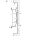
- FIG. 4 is an explanatory view showing a cross-sectional structure of the separator cup 12B in the ultrasonic atomizer 102 according to the second embodiment of the present invention.
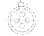
- FIG. 5 is a plan view showing the planar structure of the bottom surface BP2 of the separator cup 12B shown in FIG.
- FIG. 5 shows a plan view seen from the bottom surface BP2 side.
- FIGS. 4 and 5 the same components as those of the ultrasonic atomizing device 101 of the first embodiment are designated by the same reference numerals and description thereof will be omitted as appropriate, and the description will be centered on the characteristic parts of the second embodiment.
- the bottom surface BP2 does not have a uniform film thickness but has two types of film thicknesses. This point will be described in detail below.
- the bottom surface BP2 is divided into four thin film regions R1 having a relatively thin film thickness of 0.5 mm or less and a thick film region R2 having a relatively thick film thickness of more than 0.5 mm.
- the four thin film regions R1 are set corresponding to the four ultrasonic vibrators 2. Each of the four thin film regions R1 is set to a region including the entire ultrasonic transmission region through which the ultrasonic waves applied from the corresponding ultrasonic vibrator 2 are transmitted. Then, on the bottom surface BP2, all regions other than the four thin film regions R1 are set as the thick film region R2. Further, the film thicknesses of the side surfaces and the upper surface of the separator cup 12 are also set to be the same as the film thickness of the thick film region R2.
- the bottom surface BP2 of the separator cup 12B has four thin film regions R1 corresponding to the four ultrasonic vibrators 2.
- Each of the four thin film regions R1 includes an ultrasonic transmission region that transmits ultrasonic waves generated from the corresponding ultrasonic vibrator 2 among the four ultrasonic vibrators 2.
- the separator cup 12B of the ultrasonic atomizer 102 of the second embodiment sets the thickness ( ⁇ 0.5 mm) of the four thin film regions R1 to be thinner than the thickness of the other regions (> 0.5 mm). is doing.
- each of the four thin film regions R1 satisfies the thin film condition that the thickness is 0.5 mm or less, and the thick film region R2 satisfies the above thin film conditions. Not done.
- FIG. 8 is an explanatory view showing a cross-sectional structure of the conventional ultrasonic atomizer 200.
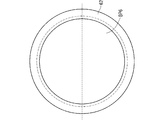
- FIG. 9 is a plan view showing the planar structure of the bottom surface BP6 of the separator cup 62 shown in FIG.
- FIG. 9 shows a plan view seen from the bottom surface BP6 side.
- FIGS. 8 and 9 the same components as those of the ultrasonic atomizer 200 shown in FIGS. 6 and 7 are designated by the same reference numerals, and the description thereof will be omitted as appropriate.
- the separator cup 62 has a uniform film thickness even on the bottom surface BP6. That is, the bottom surface BP6 is uniformly set at 1.0 mm. Further, the film thicknesses of the side surface and the upper surface of the separator cup 62 are also set to the same film thickness (1.0 mm).
- the four thin film regions R1 (at least one thin film region) satisfy the above thin film conditions and the four thin film regions R1.
- the thick film region R2, which is another region other than the above, is characterized in that it does not satisfy the above thin film conditions.
- the ultrasonic atomizer 102 of the second embodiment has the above-mentioned characteristics, and by setting the film thickness of the thick film region R2 to be relatively thicker than 0.5 mm in the separator cup 12B, the raw material The resistance to solution 15 can be maximized.
- the four thin film regions R1 each including the ultrasonic transmission region have a “thickness of 0.5 mm or less”.
- the ultrasonic atomizer 102 of the second embodiment has the effect of being able to generate the raw material solution mist MT with an appropriate amount of atomization, similarly to the ultrasonic atomizer 101 of the first embodiment.
- the thickness of the four thin film regions R1 By setting the thickness of the four thin film regions R1 to 0.3 mm or less and satisfying the limited thin film conditions as in the limited configuration of the first embodiment, even higher atomization is performed in the second embodiment. Of course, an amount of raw material solution mist MT can be produced.
Landscapes
- Special Spraying Apparatus (AREA)
Abstract
Description
図1及び図2はそれぞれこの発明の実施の形態1である超音波霧化装置101の構成を模式的に示す説明図である。図1は初期状態時(その1)、図2は原料溶液ミストMTの生成時(その2)を示している。
図4はこの発明の実施の形態2である超音波霧化装置102におけるセパレータカップ12Bの断面構造を示す説明図である。図5は図4で示したセパレータカップ12Bの底面BP2の平面構造を示す平面図である。図5では底面BP2側から視た平面図を示している。
2 超音波振動子
3 内部空洞構造体
4 ガス供給部
9 超音波伝達水
10 水槽
12,12B セパレータカップ
15 原料溶液
101,102 超音波霧化装置
BP1,BP2 底面
R1 薄膜領域
R2 厚膜領域
Claims (3)
- 原料溶液を収容するセパレータカップを下方に有する容器と、
前記容器内において前記セパレータカップの上方に設けられ、内部が空洞の内部空洞構造体と、
内部に超音波伝達媒体を収容する水槽とを備え、前記水槽及び前記セパレータカップは、前記セパレータカップの底面が前記超音波伝達媒体に浸るように位置決めされ、
前記水槽の底面に設けられる少なくとも一つの超音波振動子をさらに備え、
前記セパレータカップは、構成材質がフッ素樹脂であり厚みが薄膜条件を満足する底面を有し、
前記薄膜条件は、「底面の厚みが0.5mm以下である」ことを特徴とする、
超音波霧化装置。 - 請求項1記載の超音波霧化装置であって、
前記薄膜条件は、「底面の厚みが0.3mm以下である」という限定薄膜条件を含む、
超音波霧化装置。 - 請求項1または請求項2に記載の超音波霧化装置であって、
前記セパレータカップの底面は、前記少なくとも一つの超音波振動子に対応する少なくとも一つの薄膜領域を有し、前記少なくとも一つの薄膜領域はそれぞれ、前記少なくとも一つの超音波振動子のうち対応する超音波振動子から印加される超音波を透過させる超音波透過領域を含み、
前記セパレータカップの底面において、前記少なくとも一つの薄膜領域は前記薄膜条件を満足し、前記少なくとも一つの薄膜領域以外の他の領域は前記薄膜条件を満足しないことを特徴とする、
超音波霧化装置。
Priority Applications (8)
| Application Number | Priority Date | Filing Date | Title |
|---|---|---|---|
| JP2021513926A JP7086506B2 (ja) | 2020-01-17 | 2020-01-17 | 超音波霧化装置 |
| EP20913079.8A EP3912732B1 (en) | 2020-01-17 | 2020-01-17 | Ultrasonic atomization device |
| PCT/JP2020/001494 WO2021144959A1 (ja) | 2020-01-17 | 2020-01-17 | 超音波霧化装置 |
| US17/429,642 US20220111412A1 (en) | 2020-01-17 | 2020-01-17 | Ultrasonic atomization apparatus |
| CN202080011751.7A CN113412163A (zh) | 2020-01-17 | 2020-01-17 | 超声波雾化装置 |
| EP24204616.7A EP4464419A3 (en) | 2020-01-17 | 2020-01-17 | Ultrasonic atomization device |
| KR1020217023824A KR102627895B1 (ko) | 2020-01-17 | 2020-01-17 | 초음파 안개화 장치 |
| TW109146004A TWI775254B (zh) | 2020-01-17 | 2020-12-24 | 超音波霧化裝置 |
Applications Claiming Priority (1)
| Application Number | Priority Date | Filing Date | Title |
|---|---|---|---|
| PCT/JP2020/001494 WO2021144959A1 (ja) | 2020-01-17 | 2020-01-17 | 超音波霧化装置 |
Publications (1)
| Publication Number | Publication Date |
|---|---|
| WO2021144959A1 true WO2021144959A1 (ja) | 2021-07-22 |
Family
ID=76864120
Family Applications (1)
| Application Number | Title | Priority Date | Filing Date |
|---|---|---|---|
| PCT/JP2020/001494 Ceased WO2021144959A1 (ja) | 2020-01-17 | 2020-01-17 | 超音波霧化装置 |
Country Status (7)
| Country | Link |
|---|---|
| US (1) | US20220111412A1 (ja) |
| EP (2) | EP3912732B1 (ja) |
| JP (1) | JP7086506B2 (ja) |
| KR (1) | KR102627895B1 (ja) |
| CN (1) | CN113412163A (ja) |
| TW (1) | TWI775254B (ja) |
| WO (1) | WO2021144959A1 (ja) |
Cited By (1)
| Publication number | Priority date | Publication date | Assignee | Title |
|---|---|---|---|---|
| JP7460298B1 (ja) * | 2022-12-20 | 2024-04-02 | 東芝三菱電機産業システム株式会社 | 超音波霧化装置 |
Citations (7)
| Publication number | Priority date | Publication date | Assignee | Title |
|---|---|---|---|---|
| JPS5568576U (ja) * | 1978-11-01 | 1980-05-12 | ||
| JP2005111328A (ja) * | 2003-10-06 | 2005-04-28 | Konishi Seiko Kk | 携帯用超音波霧化装置 |
| JP2005305233A (ja) * | 2004-04-19 | 2005-11-04 | Shizuo Fujita | 成膜用霧化装置 |
| JP2007181808A (ja) * | 2005-10-12 | 2007-07-19 | Akira Tomono | 霧発生装置 |
| JP2012075577A (ja) * | 2010-09-30 | 2012-04-19 | Sanyo Electric Co Ltd | 過酸化水素水の霧化装置 |
| WO2015019468A1 (ja) | 2013-08-08 | 2015-02-12 | 東芝三菱電機産業システム株式会社 | 霧化装置 |
| JP2016190172A (ja) * | 2015-03-30 | 2016-11-10 | 株式会社Flosfia | 霧化装置および成膜装置 |
Family Cites Families (23)
| Publication number | Priority date | Publication date | Assignee | Title |
|---|---|---|---|---|
| FR2110622A5 (ja) * | 1970-10-23 | 1972-06-02 | Commissariat Energie Atomique | |
| JPS6082164A (ja) * | 1983-10-08 | 1985-05-10 | Omron Tateisi Electronics Co | 超音波霧化装置 |
| US4976259A (en) * | 1986-12-22 | 1990-12-11 | Mountain Medical Equipment, Inc. | Ultrasonic nebulizer |
| FR2690634B1 (fr) * | 1992-04-29 | 1994-10-14 | Chronotec | Dispositif de micro-pulvérisation générée par ondes ultra-sonores. |
| JPH0615757U (ja) * | 1992-07-23 | 1994-03-01 | ティーディーケイ株式会社 | 超音波霧化器 |
| FR2699510B1 (fr) * | 1992-12-23 | 1995-03-24 | Dp Medical | Dispositif de montage d'une cloison interne et d'un couvercle sur le bord périphérique d'une cuve, notamment pour nébuliseur. |
| JP2000271517A (ja) * | 1999-03-25 | 2000-10-03 | Kao Corp | 超音波噴霧装置 |
| EP1611831B1 (en) * | 2004-06-04 | 2009-05-13 | Panasonic Corporation | Mist generating device, and dishwasher and washing machine using same |
| JP4079912B2 (ja) * | 2004-06-04 | 2008-04-23 | 松下電器産業株式会社 | 食器洗浄機 |
| WO2006095816A1 (ja) * | 2005-03-11 | 2006-09-14 | Akira Tomono | 霧発生装置、および、霧放出演出装置 |
| IL183643A0 (en) * | 2007-06-04 | 2007-10-31 | Shira Inc P D Ltd | Nebulizer particularly useful for converting liquids to fine sprays at extremely low rates |
| JP5603065B2 (ja) * | 2009-01-30 | 2014-10-08 | パナソニックヘルスケア株式会社 | 滅菌物質供給装置およびアイソレータ |
| JP5365863B2 (ja) * | 2009-08-21 | 2013-12-11 | 株式会社リコー | トナーの製造装置及びトナーの製造方法 |
| WO2012043682A1 (ja) * | 2010-09-30 | 2012-04-05 | 三洋電機株式会社 | 過酸化水素水の霧化装置、滅菌物質発生装置、ガス発生装置およびアイソレータ |
| JP6064601B2 (ja) * | 2013-01-09 | 2017-01-25 | オムロンヘルスケア株式会社 | 超音波式吸入器用の薬液槽および薬液パック |
| WO2015115006A1 (ja) * | 2014-01-31 | 2015-08-06 | 株式会社良品計画 | 超音波霧化装置、超音波加湿器、及び、超音波芳香揮散器 |
| JP2016189922A (ja) * | 2015-03-31 | 2016-11-10 | 株式会社フコク | 霧化ユニット及びこの霧化ユニットに装着する霧化液充填容器、並びにこれらを組み立てた超音波霧化装置 |
| US20170072085A1 (en) * | 2015-09-16 | 2017-03-16 | The Procter & Gamble Company | Microfluidic delivery system and cartridge |
| TWI566838B (zh) * | 2016-01-08 | 2017-01-21 | Prec Machinery Research&Development Center | Ultrasonic compound rotary atomization mechanism |
| JP6577443B2 (ja) * | 2016-11-02 | 2019-09-18 | 東芝三菱電機産業システム株式会社 | 霧化装置 |
| JP6932237B2 (ja) * | 2018-02-27 | 2021-09-08 | シャープ株式会社 | 霧化装置および調湿装置 |
| WO2020241150A1 (ja) * | 2019-05-27 | 2020-12-03 | シャープ株式会社 | 超音波霧化装置および調湿装置 |
| JP7228160B2 (ja) * | 2019-06-03 | 2023-02-24 | 株式会社デンソー | ミスト生成装置、成膜装置、及び成膜装置を用いた成膜方法 |
-
2020
- 2020-01-17 KR KR1020217023824A patent/KR102627895B1/ko active Active
- 2020-01-17 EP EP20913079.8A patent/EP3912732B1/en active Active
- 2020-01-17 WO PCT/JP2020/001494 patent/WO2021144959A1/ja not_active Ceased
- 2020-01-17 US US17/429,642 patent/US20220111412A1/en active Pending
- 2020-01-17 EP EP24204616.7A patent/EP4464419A3/en active Pending
- 2020-01-17 CN CN202080011751.7A patent/CN113412163A/zh active Pending
- 2020-01-17 JP JP2021513926A patent/JP7086506B2/ja active Active
- 2020-12-24 TW TW109146004A patent/TWI775254B/zh active
Patent Citations (7)
| Publication number | Priority date | Publication date | Assignee | Title |
|---|---|---|---|---|
| JPS5568576U (ja) * | 1978-11-01 | 1980-05-12 | ||
| JP2005111328A (ja) * | 2003-10-06 | 2005-04-28 | Konishi Seiko Kk | 携帯用超音波霧化装置 |
| JP2005305233A (ja) * | 2004-04-19 | 2005-11-04 | Shizuo Fujita | 成膜用霧化装置 |
| JP2007181808A (ja) * | 2005-10-12 | 2007-07-19 | Akira Tomono | 霧発生装置 |
| JP2012075577A (ja) * | 2010-09-30 | 2012-04-19 | Sanyo Electric Co Ltd | 過酸化水素水の霧化装置 |
| WO2015019468A1 (ja) | 2013-08-08 | 2015-02-12 | 東芝三菱電機産業システム株式会社 | 霧化装置 |
| JP2016190172A (ja) * | 2015-03-30 | 2016-11-10 | 株式会社Flosfia | 霧化装置および成膜装置 |
Non-Patent Citations (1)
| Title |
|---|
| See also references of EP3912732A4 |
Cited By (1)
| Publication number | Priority date | Publication date | Assignee | Title |
|---|---|---|---|---|
| JP7460298B1 (ja) * | 2022-12-20 | 2024-04-02 | 東芝三菱電機産業システム株式会社 | 超音波霧化装置 |
Also Published As
| Publication number | Publication date |
|---|---|
| KR102627895B1 (ko) | 2024-01-23 |
| TW202138067A (zh) | 2021-10-16 |
| EP3912732B1 (en) | 2025-07-02 |
| EP3912732A4 (en) | 2022-08-31 |
| TWI775254B (zh) | 2022-08-21 |
| EP4464419A3 (en) | 2025-02-12 |
| KR20210109579A (ko) | 2021-09-06 |
| EP3912732A1 (en) | 2021-11-24 |
| JP7086506B2 (ja) | 2022-06-20 |
| CN113412163A (zh) | 2021-09-17 |
| JPWO2021144959A1 (ja) | 2021-07-22 |
| US20220111412A1 (en) | 2022-04-14 |
| EP4464419A2 (en) | 2024-11-20 |
Similar Documents
| Publication | Publication Date | Title |
|---|---|---|
| KR101859304B1 (ko) | 무화 장치 | |
| JP7086506B2 (ja) | 超音波霧化装置 | |
| JP4990707B2 (ja) | 超音波霧発生装置 | |
| JP2005305233A (ja) | 成膜用霧化装置 | |
| TWI773008B (zh) | 超音波霧化裝置 | |
| JPWO2002051707A1 (ja) | Dlc膜コーティングプラスチック容器の製造装置及びその製造方法 | |
| WO2021031261A1 (zh) | 聚焦超声雾化装置 | |
| HK40052476A (en) | Ultrasonic atomization device | |
| CN204124616U (zh) | 一种原料储罐 | |
| HK40052524A (en) | Ultrasonic atomizing device | |
| HK40052524B (en) | Ultrasonic atomizing device | |
| JP2009262012A (ja) | 超音波噴霧装置 | |
| CN119608477B (zh) | 基于高频声波的液体处理装置 | |
| WO2025057992A1 (ja) | 霧化装置及び製膜装置。 | |
| RU2644867C1 (ru) | Форсунка акустическая | |
| JPS6314654B2 (ja) | ||
| CN108561998A (zh) | 一种带有中央雾化管的超声波加湿器 | |
| CN119608477A (zh) | 基于高频声波的液体处理装置 | |
| JPS60164032A (ja) | 液体入り防振体 | |
| CN116871105A (zh) | 可雾化油性或粘稠液体的雾化片模组及雾化设备 | |
| CN117066068A (zh) | 高阻隔容器的喷涂制备方法 | |
| RU2020106071A (ru) | Конический форсуночный скруббер | |
| RU2020100449A (ru) | Конический форсуночный скруббер | |
| JPH0127793B2 (ja) | ||
| RU2006125265A (ru) | Термоядерный реактор |
Legal Events
| Date | Code | Title | Description |
|---|---|---|---|
| ENP | Entry into the national phase |
Ref document number: 2021513926 Country of ref document: JP Kind code of ref document: A |
|
| ENP | Entry into the national phase |
Ref document number: 20217023824 Country of ref document: KR Kind code of ref document: A |
|
| ENP | Entry into the national phase |
Ref document number: 2020913079 Country of ref document: EP Effective date: 20210817 |
|
| 121 | Ep: the epo has been informed by wipo that ep was designated in this application |
Ref document number: 20913079 Country of ref document: EP Kind code of ref document: A1 |
|
| NENP | Non-entry into the national phase |
Ref country code: DE |
|
| WWG | Wipo information: grant in national office |
Ref document number: 2020913079 Country of ref document: EP |