WO2021145108A1 - 自動分析装置 - Google Patents
自動分析装置 Download PDFInfo
- Publication number
- WO2021145108A1 WO2021145108A1 PCT/JP2020/045937 JP2020045937W WO2021145108A1 WO 2021145108 A1 WO2021145108 A1 WO 2021145108A1 JP 2020045937 W JP2020045937 W JP 2020045937W WO 2021145108 A1 WO2021145108 A1 WO 2021145108A1
- Authority
- WO
- WIPO (PCT)
- Prior art keywords
- measuring instrument
- automatic analyzer
- cleaning
- analyzer according
- unit
- Prior art date
- Legal status (The legal status is an assumption and is not a legal conclusion. Google has not performed a legal analysis and makes no representation as to the accuracy of the status listed.)
- Ceased
Links
Images









Classifications
-
- G—PHYSICS
- G01—MEASURING; TESTING
- G01N—INVESTIGATING OR ANALYSING MATERIALS BY DETERMINING THEIR CHEMICAL OR PHYSICAL PROPERTIES
- G01N35/00—Automatic analysis not limited to methods or materials provided for in any single one of groups G01N1/00 - G01N33/00; Handling materials therefor
- G01N35/00584—Control arrangements for automatic analysers
- G01N35/00594—Quality control, including calibration or testing of components of the analyser
- G01N35/00613—Quality control
-
- G—PHYSICS
- G01—MEASURING; TESTING
- G01N—INVESTIGATING OR ANALYSING MATERIALS BY DETERMINING THEIR CHEMICAL OR PHYSICAL PROPERTIES
- G01N35/00—Automatic analysis not limited to methods or materials provided for in any single one of groups G01N1/00 - G01N33/00; Handling materials therefor
- G01N35/00584—Control arrangements for automatic analysers
- G01N35/00722—Communications; Identification
- G01N35/00732—Identification of carriers, materials or components in automatic analysers
-
- G—PHYSICS
- G01—MEASURING; TESTING
- G01N—INVESTIGATING OR ANALYSING MATERIALS BY DETERMINING THEIR CHEMICAL OR PHYSICAL PROPERTIES
- G01N35/00—Automatic analysis not limited to methods or materials provided for in any single one of groups G01N1/00 - G01N33/00; Handling materials therefor
- G01N35/02—Automatic analysis not limited to methods or materials provided for in any single one of groups G01N1/00 - G01N33/00; Handling materials therefor using a plurality of sample containers moved by a conveyor system past one or more treatment or analysis stations
- G01N35/026—Automatic analysis not limited to methods or materials provided for in any single one of groups G01N1/00 - G01N33/00; Handling materials therefor using a plurality of sample containers moved by a conveyor system past one or more treatment or analysis stations having blocks or racks of reaction cells or cuvettes
-
- G—PHYSICS
- G01—MEASURING; TESTING
- G01N—INVESTIGATING OR ANALYSING MATERIALS BY DETERMINING THEIR CHEMICAL OR PHYSICAL PROPERTIES
- G01N35/00—Automatic analysis not limited to methods or materials provided for in any single one of groups G01N1/00 - G01N33/00; Handling materials therefor
- G01N35/10—Devices for transferring samples or any liquids to, in, or from, the analysis apparatus, e.g. suction devices, injection devices
- G01N35/1004—Cleaning sample transfer devices
-
- G—PHYSICS
- G01—MEASURING; TESTING
- G01N—INVESTIGATING OR ANALYSING MATERIALS BY DETERMINING THEIR CHEMICAL OR PHYSICAL PROPERTIES
- G01N35/00—Automatic analysis not limited to methods or materials provided for in any single one of groups G01N1/00 - G01N33/00; Handling materials therefor
- G01N2035/00178—Special arrangements of analysers
- G01N2035/00326—Analysers with modular structure
-
- G—PHYSICS
- G01—MEASURING; TESTING
- G01N—INVESTIGATING OR ANALYSING MATERIALS BY DETERMINING THEIR CHEMICAL OR PHYSICAL PROPERTIES
- G01N35/00—Automatic analysis not limited to methods or materials provided for in any single one of groups G01N1/00 - G01N33/00; Handling materials therefor
- G01N2035/00465—Separating and mixing arrangements
- G01N2035/00534—Mixing by a special element, e.g. stirrer
-
- G—PHYSICS
- G01—MEASURING; TESTING
- G01N—INVESTIGATING OR ANALYSING MATERIALS BY DETERMINING THEIR CHEMICAL OR PHYSICAL PROPERTIES
- G01N35/00—Automatic analysis not limited to methods or materials provided for in any single one of groups G01N1/00 - G01N33/00; Handling materials therefor
- G01N35/00584—Control arrangements for automatic analysers
- G01N35/00722—Communications; Identification
- G01N2035/00891—Displaying information to the operator
Definitions
- the present invention relates to an automatic analyzer.
- the automatic analyzer In clinical tests that perform qualitative or quantitative analysis of components contained in biological samples such as blood and urine of patients, an automatic analyzer that automates a series of test steps is known.
- the automatic analyzer generally includes various processing units such as a plurality of dispensing mechanisms for separating a predetermined amount of a sample and a reagent from a container to a reaction container, a stirring mechanism, and a washing mechanism.
- the sample and the reagent are sucked by the sample dispensing mechanism and the reagent dispensing mechanism and discharged toward the reaction vessel (in the present specification, the sample dispensing mechanism and the reagent dispensing mechanism are collectively referred to). (Sometimes referred to as "dispensing mechanism"). Further, the sample and the reagent chemically react with each other by stirring or the like by the stirring mechanism, and then the reaction solution is sent to the detector to perform various tests. After that, the dispensing mechanism undergoes a cleaning operation in the cleaning tank and also executes a moving operation between the above operations.
- the operations such as suction, discharge, stirring, and cleaning in each processing unit as described above are performed according to the design values, that is, the above operations must be appropriately adjusted in order to ensure the analysis performance of the automatic analyzer. is necessary. For example, in order to prevent the introduction of reagents between different samples, it is necessary that the dispensing mechanism is washed with an appropriate amount of washing water. Further, from the viewpoint of ensuring the accuracy of the dispensing amount, it is important to accurately adjust the position of the nozzle of the dispensing mechanism.
- Patent Document 1 discloses an automatic analyzer capable of photographing a suction operation, a discharge operation, and a cleaning operation of a sample dispensing mechanism and a reagent dispensing mechanism by a camera (imaging unit) as a method for confirming the operation of a nozzle. ..
- the device of Patent Document 1 employs a camera for each of the plurality of dispensing mechanisms. Therefore, in order to confirm the operation of the nozzles of the plurality of dispensing mechanisms in one device, a plurality of cameras are required. The increase in the number of cameras causes an increase in the manufacturing cost of the device.
- An object of the present invention is to provide an automatic analyzer capable of measuring operations in a plurality of processing units and ensuring analysis performance while suppressing an increase in manufacturing cost.
- the automatic analyzer is arranged in each of the plurality of processing units that execute the operations related to the analysis and the plurality of processing units, and measures the operations of the plurality of processing units. It includes a plurality of measuring instrument installation units configured so that the measuring instruments can be installed, and a control unit that controls the plurality of processing units. Each of the plurality of measuring instrument installation units is configured so that the measuring instrument can be removed and the removed measuring instrument can be installed in another measuring instrument installation unit.
- an automatic analyzer capable of measuring operations in a plurality of processing units and ensuring analysis performance while suppressing an increase in manufacturing cost.
- the schematic block diagram of the automatic analyzer 100 which concerns on 1st Embodiment.
- the schematic plan view explaining the outline of the structure of the reagent dispensing mechanism 110 which concerns on 1st Embodiment.
- the schematic plan view explaining the outline of the structure of the stirring paddle drive mechanism 112 which concerns on 1st Embodiment.
- the schematic plan view explaining the outline of the structure of the reaction liquid suction mechanism 116 which concerns on 1st Embodiment.
- the schematic plan view explaining the outline of the structure of the sample dispensing mechanism 117 which concerns on 1st Embodiment.
- the schematic plan view explaining the outline of the structure of the BF separation mechanism 118 which concerns on 1st Embodiment.
- FIG. 1 The schematic perspective view explaining the structure of the cleaning mechanism W1 provided in the reagent dispensing mechanism 110, and the measuring instrument installation part BX1.
- FIG. 5 is a flowchart of an operation of measuring and adjusting the amount of washing water in the plurality of washing mechanisms W1 to 5 according to the first embodiment.
- the schematic block diagram of the automatic analyzer 100 which concerns on 2nd Embodiment.
- FIG 5 is a cross-sectional view showing a specific configuration example of the measuring instrument installation unit BX42.
- the figure which shows an example of the image obtained by photographing the sample container 101 and the like.
- the schematic block diagram of the automatic analyzer 100 which concerns on 3rd Embodiment.
- the schematic block diagram of the automatic analyzer 100 which concerns on 4th Embodiment.
- the schematic block diagram of the automatic analyzer 100 which concerns on 5th Embodiment.
- the schematic block diagram of the automatic analyzer 100 which concerns on 6th Embodiment.
- the schematic block diagram of the automatic analyzer 100 which concerns on 7th Embodiment.
- the schematic block diagram explaining the comparative example of 8th Embodiment The schematic block diagram of the automatic analyzer 100 which concerns on 8th Embodiment.
- FIG. 1 is a schematic configuration diagram of the automatic analyzer 100 according to the first embodiment.
- the automatic analyzer 100 includes a main body unit 100A, a control unit 11, an input unit 12, a display unit 13, a storage unit 14, and an external control unit 15.
- the main body 100A has various configurations for executing automatic analysis of the sample, as will be described later.
- the control unit 11 controls the entire body unit 100A.
- the input unit 12 is a device for inputting commands from the operator and various data to the control unit 11.
- the display unit 13 is a display device for displaying the analysis result of the sample and the like.
- the storage unit 41 is a storage device that stores computer programs and various data for controlling the control unit 11, and is, for example, a hard disk drive or a semiconductor memory device.
- the external control unit 15 is an external electronic terminal such as a notebook computer or a tablet, and controls the main body unit 100A independently of the control unit 11.
- the automatic analyzer 100 includes a sample container rack 102, a rack transfer line 103, a reagent disk 106, and an incubator (reaction disk) 108 in the main body 100A.
- the sample container rack 102 stores a plurality of sample containers 101 for storing biological samples (hereinafter referred to as samples) such as blood and urine.
- the rack transport line 103 is a transport path for transporting the sample container rack 102.
- the reagent disk 106 is a disk-shaped container that houses and keeps the reagent container 104 warm. Various reagents containing compounds, magnetic particles, etc. that react with specific components in the sample are stored in the reagent container 104.
- the inside of the reagent disk 106 is maintained at a predetermined temperature.
- the reagent reacts with the sample in the reaction vessel and is used for the analysis of various samples.
- the surface of the reagent disc 106 is covered with the reagent disc cover 105.
- the reagent disc cover 105 is provided with an opening 105a for passing the reagent dispensing mechanism 110, which will be described later.
- the incubator 108 is a disk-shaped container for accommodating a plurality of reaction containers 107 for mixing a sample and a reagent.
- the reaction vessel holding unit 109 is a holding unit for storing an unused reaction vessel. The used reaction vessel 107 is discarded in the waste hole Hd.
- the automatic analyzer 100 includes a reagent dispensing mechanism 110, a stirring paddle drive mechanism 112, a detection mechanism 115, a reaction liquid suction mechanism 116 (116a, 116b), a sample dispensing mechanism 117, and a BF. It is provided with a separation mechanism 118 and a reaction vessel transport mechanism 119.
- the reagent dispensing mechanism 110 is configured to be able to rotate and move up and down about the rotation axis, suck the reagent held in the reagent container 104 in the reagent disk 106, and suck the sucked reagent into the reaction container on the incubator 108. Discharge to 107.
- the stirring paddle driving mechanism 112 is a device for driving a paddle for stirring magnetic particles and the like in the reagent container 104.
- the detection mechanism 115 receives the reaction liquid from the reaction vessel 107 via the reaction liquid suction mechanism 116 (116a, 116b) and executes the analysis of the sample.
- the detection mechanism 115 can include a plurality of detection units in parallel, and the reaction liquid suction mechanism 116 can also include a plurality of suction units (for example, two suction units 116a and 116b) accordingly.
- the reaction liquid suction mechanism 116 can also include a plurality of suction units (for example, two suction units 116a and 116b) accordingly.
- paddles and various nozzles are collectively referred to as "rod-shaped members".
- the sample dispensing mechanism 117 sucks the sample from the sample container 101 and discharges the sample toward the reaction container 107 arranged in the incubator 108.
- the BF separation mechanism 118 is a cleaning mechanism for supplying a BF separation solution to the reaction vessel 107 to perform pre-cleaning for cleaning unreacted components.
- the reaction vessel transport mechanism 119 is a three-axis transport mechanism that can move in three directions of the X-axis, the Y-axis, and the Z-axis, and grips the reaction vessel 107 to transport the reaction vessel 107 to a predetermined position.
- the cleaning mechanisms W1 to W5 are provided as devices for cleaning the reagent dispensing mechanism 110, the stirring paddle driving mechanism 112, the reaction liquid suction mechanism 116, the sample dispensing mechanism 117, and the BF separation mechanism 118. ..
- each cleaning mechanism W1 to W5 is provided with a measuring instrument for measuring the operation of the cleaning mechanisms W1 to S5, for example, a camera.
- each cleaning mechanism W1 to W5 includes a measuring instrument installation unit (BX) into which the measuring instrument SS can be freely inserted and removed.
- the measuring instrument SS is movable from one measuring instrument installation unit to another measuring instrument installation unit.
- the measuring instrument SS can be shared among a plurality of measuring instrument installation parts, whereby the number of measuring instrument SSs can be reduced and the manufacturing cost can be suppressed.
- measuring instrument installation unit BX when the measuring instrument installation unit is collectively referred to as “measuring instrument installation unit BX", and when individual measuring instrument installation units provided in one processing unit are referred to, “measuring instrument installation unit BXi" is used. It may be called with a number such as ".
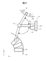
- FIG. 2 is a schematic plan view illustrating the outline of the configuration of the reagent dispensing mechanism 110.
- the reagent dispensing mechanism 110 includes a rotation shaft AX1, a shaft SF1 that rotates about the rotation shaft AX1, and a nozzle NZ1 (not shown in FIG. 2) attached to the tip of the shaft SF1.
- the cleaning mechanism W1 is arranged at a passing position of the nozzle NZ1 and cleans the nozzle NZ1 that has finished the dispensing operation.
- the cleaning mechanism W1 includes a measuring instrument installation unit BX1 to which a measuring instrument SS (here, as an example, a camera capable of photographing the cleaning state) for measuring the cleaning state can be installed.
- the reagent dispensing mechanism 110 is configured to be vertically movable by a vertically moving mechanism (not shown).
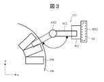
- FIG. 3 is a schematic plan view illustrating the outline of the configuration of the stirring paddle drive mechanism 112.
- the stirring paddle drive mechanism 112 includes a rotating shaft AX2, a shaft SF2 that rotates about the rotating shaft AX2, and a stirring paddle (not shown in FIG. 3) attached to the tip of the shaft SF2.
- the cleaning mechanism W2 is arranged at a position where the stirring paddle passes, and cleans the stirring paddle after the stirring operation is completed.
- the shaft SF2 rotates around the rotation shaft AX2 to perform a cleaning operation of the stirring paddle with the cleaning liquid and a stirring operation of magnetic particles precipitated in the reagent container 104 installed on the reagent disk 106. Is repeated.
- the cleaning mechanism W2 includes a measuring instrument installation unit BX2 on which a measuring instrument SS for measuring the state of cleaning can be installed.
- the measuring instrument SS can be freely inserted and removed from the measuring instrument installation unit BX1, and the measuring instrument SS removed from the other measuring instrument installation unit can be attached and used.
- the stirring paddle drive mechanism 112 is configured to be vertically movable by a vertical movement mechanism (not shown).
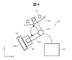
- FIG. 4 is a schematic plan view illustrating the outline of the configuration of the reaction liquid suction mechanism 116. Since the two reaction liquid suction mechanisms 116a and 116b have the same structure, only one of them is illustrated in FIG.
- the reaction liquid suction mechanism 116 includes a rotating shaft AX3, a shaft SF3 that rotates about the rotating shaft AX3, and a nozzle (not shown) attached to the tip of the shaft SF3.
- the reaction liquid sucked from the reaction vessel 107 by the reaction liquid suction mechanism 116 is sent to the detection mechanism 115 via the reaction liquid suction flow path.
- a cleaning mechanism W3 is arranged at a passing position of the nozzle. As the shaft SF3 rotates about the rotation shaft AX3, the nozzle is cleaned by the cleaning mechanism W3.
- the cleaning mechanism W3 includes a measuring instrument installation unit BX3 on which a measuring instrument SS for measuring the state of cleaning can be installed.
- the measuring instrument SS can be freely inserted and removed from the measuring instrument installation unit BX3, and the measuring instrument SS removed from the other measuring instrument installation unit can be attached and used.
- the reaction liquid suction mechanism 116 is configured to be vertically movable by a vertical movement mechanism (not shown).
- FIG. 5 is a schematic plan view illustrating the outline of the configuration of the sample dispensing mechanism 117.
- the sample dispensing mechanism 117 includes a rotating shaft AX4, a shaft SF4 that rotates about the rotating shaft AX4, and a nozzle (not shown in FIG. 5) attached to the tip of the shaft SF4.
- the cleaning mechanism W4 is arranged at a position where the nozzle passes, and cleans the nozzle after the sample dispensing operation is completed.
- the cleaning mechanism W4 By rotating the shaft SF4 around the rotation shaft AX4, the cleaning operation in the cleaning mechanism W4, the operation of sucking the sample from the sample container 101, and the operation of discharging the sample to the reaction container 107 installed on the incubator 108. And are repeated.
- the cleaning mechanism W4 performs a cleaning operation in order to prevent contamination due to contamination of the previous sample when the next sample is dispensed.
- the cleaning mechanism W4 includes a measuring instrument installation unit BX4 on which a measuring instrument SS for measuring the state of cleaning can be installed.
- the measuring instrument SS can be freely inserted and removed from the measuring instrument installation unit BX4, and the measuring instrument SS removed from the other measuring instrument installation unit can be attached and used.
- FIG. 6 is a schematic plan view illustrating the outline of the configuration of the BF separation mechanism 118.
- the BF separation mechanism 118 includes a rotation shaft AX5, a shaft SF5 that rotates about the rotation shaft AX5, and a nozzle (not shown in FIG. 6) attached to the tip of the shaft SF5.
- the cleaning mechanism W5 is arranged at the passage position of the nozzle and cleans the nozzle after the BF separation operation is completed.
- the cleaning mechanism W5 includes a measuring instrument installation unit BX5 on which a measuring instrument SS for measuring the state of cleaning can be installed.
- the measuring instrument SS can be freely inserted and removed from the measuring instrument installation unit BX5, and the measuring instrument SS removed from the other measuring instrument installation unit can be attached and used.
- FIGS. 2 to 6 various nozzles and paddles have been described as a structure that rotates about a rotation axis, but the present invention is not limited to this, and the three-axis drive is such that the nozzles and paddles move in the orthogonal three-axis directions.
- a mechanism may be adopted.
- the reaction liquid suction mechanism 116 may be fixed, and instead, a configuration may be adopted in which the reaction vessel 107 is moved to the reaction liquid suction mechanism 116 side by an actuator (not shown).
- a plurality of processing units for example, reagent dispensing mechanism 110, stirring paddle driving mechanism 112, reaction liquid suction mechanism 116, sample dispensing mechanism 117, BF separation.
- Measuring instrument installation units BX1 to BX1 to 5 are arranged in each of the mechanisms 118), and a measuring instrument SS (camera or the like) can be installed.
- the measuring instrument SS may be installed in a predetermined measuring instrument installation unit when inspecting the operation of each processing unit, and can be removed and moved to another measuring instrument installation unit after the inspection is completed. Therefore, according to this first embodiment, one measuring instrument SS can be shared among a plurality of processing units, and the number of measuring instrument SSs can be reduced. This leads to a reduction in the manufacturing cost of the device.
- FIG. 7 is a schematic perspective view illustrating the configurations of the cleaning mechanism W1 and the measuring instrument installation unit BX1 provided in the reagent dispensing mechanism 110.
- the configurations of the cleaning mechanisms W1 to W5 may be substantially the same, and the configurations of the measuring instrument installation units BX1 to BX5 may be substantially the same. Therefore, the configurations of the cleaning mechanism W1 and the measuring instrument installation unit are described below. Only will be described with reference to the figure.
- the reagent dispensing mechanism 110 includes a rotating shaft AX1, a shaft SF1, and a nozzle NZ1, and the rotating shaft AX1 rotates and moves up and down by the driving force of the actuator MT1.
- the cleaning mechanism W1 mainly includes a flow path FP1 through which a cleaning liquid such as pure water flows, a water amount adjusting valve V1 for adjusting the amount of water in the flow path FP1, and a solenoid valve EV1 for opening and closing the flow path under control from the control unit 11. It is composed of a cleaning tank 606 that receives the discharged cleaning liquid and a waste liquid pipe 607 that wastes the cleaning liquid. If the water amount adjusting valve V1 is provided with an actuator, the opening / closing amount and the water amount may be adjusted by the control unit 11.
- a sensor window 703 is provided on one side surface of the cleaning tank 606, and the above-mentioned measuring instrument SS is arranged in the sensor window 703.
- the sensor window 703 may be composed of, for example, an acrylic plate.
- the measuring instrument installation unit BX1 is arranged adjacent to the cleaning mechanism W1 and has a structure covered by the device cover 706.
- the measuring instrument installation unit BX1 includes a measuring instrument accommodating unit 701, a lock mechanism 702, a measuring instrument sensor 704, and an identification label 705.
- the measuring instrument accommodating unit 701 is a housing in which the internal measuring instrument SS is installed, and its installation position can be adjusted by an adjustment mechanism (not shown).
- the lock mechanism 702 is a mechanism for fixing the measuring instrument SS installed inside the measuring instrument accommodating portion 701.
- the measuring instrument sensor 704 is a sensor that detects whether or not the measuring instrument SS is installed in the measuring instrument accommodating portion 701.
- the detection method of the measuring instrument sensor 704 does not matter as long as the presence of the SS of the measuring instrument can be detected, but for example, a pressure sensor, an optical sensor, a hall sensor, a weight sensor, an optical sensor, a proximity sensor, etc. are the measuring instrument sensor 704. Can be adopted as.
- the identification label 705 is installed for the purpose of easily identifying a desired measuring instrument installation unit from a plurality of measuring instrument installation units BX1 to BX1 to 5 on the automatic analyzer 100.
- An LED light may be provided instead of the identification label 705, and the control unit 11 may instruct the LED light of the desired measuring instrument installation unit to blink.
- the measuring instrument SS is a camera
- the inside of the cleaning tank 606 and the image of the background image plate 800 can be measured or photographed through the sensor window 703.
- the image inside the washing tank 606 can be taken with the background image of the background image board 800 as the background.
- a connector or a terminal may be provided on the measuring instrument installation unit BX1.
- the background image board 800 is a machine-readable text 802 (for example, 1) including a positioning mark 801 for correcting the installation position of the measuring instrument SS and adjusting the position of a nozzle or the like and device information such as a serial number and an adjustment location. Dimension or two-dimensional code) is described.
- a plurality of measuring instrument installation units BX1 to BX1 to 5 are provided on the automatic analyzer 100, and different adjustment criteria are prepared for each measuring instrument installation unit BX1 to 5. Therefore, there is a concern that the user mistakenly installs the measuring instrument SS in another measuring instrument installation unit and adjusts it with a different adjustment standard by the automatic adjustment tool described later.
- the control unit 11 confirms that the measuring instrument SS is correctly installed in the desired measuring instrument installation unit.
- a proximity wireless technology such as RFID including device information is used instead of the measuring instrument sensor 704, the machine-readable text 802 of the background image is unnecessary.
- the camera When the measuring instrument SS is a camera, the camera may be composed of a lens, an image sensor (image element), a control unit for controlling them, and a communication unit. By wired or wireless connection, it is possible to connect to the control unit 11 or the external control unit 15 of the automatic analyzer 100 and transfer the image taken by the camera to the outside.
- a general-purpose electronic terminal having a lens and an image sensor, such as a smartphone or a digital camera, may be used.
- the measuring instrument SS may be a CCD camera, an infrared camera, or the like instead of the general-purpose camera.
- the measuring instrument SS may be an optical sensor, a linear image sensor, or the like instead of a camera.
- the image sensor for example, CCD
- the image sensor preferably has an adjustment accuracy of about 0.1 mm.
- the adjustment accuracy can be calculated from the following equation 1.
- Pixel resolution Y-direction visual field size (mm) / Number of pixels in the y-direction of the CCD
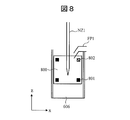
- FIG. 8 shows an example of an image when the cleaning tank 606 and the background image board 800 are photographed by using the camera as the measuring instrument SS mounted on the measuring instrument installation unit BX1 in the configuration of FIG. 7.
- the camera can simultaneously capture the nozzle NZ1 of the reagent dispensing mechanism 110, the positioning mark 801 of the background image plate 800, and the machine-readable text 802.
- grasping the positional relationship between the positioning mark 801 and the nozzle NZ1 in the image it is possible to grasp whether or not the nozzle NZ1 is in an appropriate position. Further, it can be determined from the image of the discharged cleaning liquid (803) whether or not the cleaning liquid is properly discharged from the flow path FP1 toward the nozzle NZ1.
- FIG. 9 shows an example of an image displayed on the display unit 13 when a cleaning liquid (803) having an appropriate amount of water (according to the design value) is discharged toward the nozzle NZ1.
- a cleaning liquid (803) having an appropriate amount of water accordinging to the design value
- FIG. 9 it is determined that all the cleaning liquids (803) are discharged toward the nozzles NZ1 from the relative positions of the cleaning liquids (803) with respect to the nozzle NZ1 and the shape of the image.
- the relative position of the cleaning liquid (803) with respect to the nozzle NZ1 the liquid amount of the cleaning liquid judged from the image, and other physical quantity standards such as the shape and feature amount of the image are referred to as "predetermined standards".
- FIG. 10 shows an example of an image when the amount of water in the cleaning liquid (803) is too small compared to the design value.
- an image showing that a part of the cleaning liquid (803) does not reach the nozzle NZ1 of the reagent dispensing mechanism 110 and falls downward is obtained.
- the cleaning liquid is too small compared to the design value.
- the nozzle NZ1 cannot be sufficiently washed, and the reagent may be carried over between the reagent containers, resulting in deterioration of the analysis performance.
- FIG. 11 shows an example of an image when the amount of water in the cleaning liquid (803) is excessive compared to the design value.
- the discharge angle is deviated due to the excessive amount of water in the cleaning liquid, and the cleaning liquid is not correctly applied to the nozzle NZ110.
- the cleaning liquid is wasted, the amount of cleaning water brought into the reagent container increases, and the reagent in the reagent container is diluted.
- the measuring instrument SS for example, a camera
- the state of cleaning by the cleaning mechanism W1 is measured, and the suitability of cleaning is appropriate. Can be judged. Since the measuring instrument SS can be sequentially inserted into and used in a plurality of measuring instrument installation units BX1 to 5, one measuring instrument SS can be shared by a plurality of cleaning mechanisms W1 to 5, whereby the measuring instrument SS can be shared. The manufacturing cost can be reduced. Further, there are effects such as improvement of accuracy by adjustment work using a measuring instrument, suppression of variation in adjustment by an apparatus and an adjustment worker, and shortening of adjustment time.
- FIG. 12 shows an operation in which measuring instruments SS are sequentially installed (moved) in a plurality of cleaning mechanisms W1 to W5 each provided with a measuring instrument installation unit 201 to measure and adjust the amount of cleaning water in the plurality of cleaning mechanisms W1 to 5. It is a flowchart of. The operation of this flowchart is executed according to the automatic adjustment tool for automatically adjusting the operation of the cleaning mechanisms W1 to W5 stored in the storage unit 14.
- the automatic analyzer 100 stores various software such as a measurement execution tool for executing a normal measurement operation, a test tool for confirming the operation of each mechanism, and a maintenance tool for executing a maintenance operation in the storage unit 14.
- the automatic adjustment tool is a tool that executes the following steps S101 to 119, and may be incorporated in the system software, may be incorporated in the adjustment software installed in the external control unit 11, or may be a single software.
- the control unit 11 calculates the adjustment points (n points) and saves the calculation result in the storage unit 14 (step S101).
- the control unit 11 instructs the user to install the measuring instrument SS in the predetermined measuring instrument installation unit BX1 (step S102).
- a guidance screen (details will be described later) as shown in FIG. 13 can be displayed on the display unit 13 to indicate the position of the measuring instrument installation unit on which the measuring instrument SS should be installed.
- the user attaches the measuring instrument SS to the predetermined measuring instrument installation unit BX1 according to this instruction.
- the control unit 11 reads the machine-readable text 802 from the background image board 800 and confirms the position where the measuring instrument SS should be attached (step S103). ).
- the control unit 11 transmits the information of the measuring instrument installation unit BX1 via the proximity wireless communication or the connector. Can be read.
- control unit 11 determines whether or not the mounting position information read in step S103 and the mounting position on the automatic adjustment tool match (step S104). If the measuring instrument SS is installed in the measuring instrument installation unit BX1 that is not planned, or if the machine-readable text 802 cannot be read, the control unit 11 outputs an alarm to the display unit 13 (step S105).
- the control unit 11 opens the solenoid valve EV1 and discharges the cleaning liquid from the flow path FP toward the nozzle NZ1.
- the step is carried out (step S106).
- the measuring instrument SS (camera) measures or photographs the cleaning process, and stores the measurement result or the image in the storage unit 14 (step S107).
- the control unit 11 determines from the measurement result or the captured image whether or not the amount of the cleaning liquid from the cleaning mechanism W1 is within the range of the "predetermined standard" (step S108). At this time, it is possible to correct an error in the installation position of the measuring instrument SS based on the position of the positioning mark 801 of the background image plate 800.
- the determination method in step S108 may be a method using image processing for comparing with an image that serves as a "predetermined reference" stored in the storage unit 14, or features such as a distance between the reagent dispensing mechanism 110 and the cleaning liquid. A method of calculating the amount and determining whether or not it is a "predetermined standard" may also be used. Further, the captured image may be displayed on the display unit 13 and the user may visually determine the image.
- step S108 when it is determined that the amount of cleaning water of the cleaning mechanism W1 is out of the predetermined reference range (NO in step S108), an alarm is output to the display unit 13 (step S109). After that, it is determined whether the amount of washing water is excessive or conversely too small (step S110). If the amount of wash water is too small, the control unit 11 displays an instruction screen instructing the user to open the water amount adjusting valve V1 (step S111). The instruction screen can be a screen as shown in FIG. 14, which will be described later. On the other hand, when it is determined that the amount of washing water is excessive, the control unit 11 displays a screen prompting the user to close the water amount adjusting valve V1 (step S112).
- step S111 or step S112 the opening / closing degree adjustment operation in step S111 or step S112 is automatically changed (the operation of the cleaning unit is changed). You may.
- the control unit 11 repeats steps S106 to S112 until the amount of washing water by the washing mechanism W1 is within a predetermined range.
- step S108 When the control unit 11 determines that the cleaning mechanism W1 has been adjusted so that an appropriate amount of cleaning water is discharged (YES in step S108), a display prompting the user to remove the measuring instrument SS from the measuring instrument installation unit BX1 is displayed. It is displayed on the unit 13 (step S113). Then, the control unit 11 determines whether or not the adjustment execution number i is less than the predetermined number n (step S114). If the number of adjustments i has reached n, the process proceeds to step S116. If n has not been reached, the control unit 11 adds 1 to the adjustment execution number i and updates the adjustment execution number i (step S115).
- step S116 the control unit 11 captures an image of the measuring instrument installation unit BX1 by the measuring instrument SS (step S116), and based on the captured image, whether or not the measuring instrument SS has been removed from the measuring instrument installation unit BX1. To confirm. If the measuring operation of the automatic analyzer 100 is started in a state where the measuring instrument SS is left behind in the measuring instrument installation portion BX1, there is a possibility that the probe or the like may be damaged or the parts of the automatic analyzer 100 may be damaged. The image taken in step S116 is confirmed, and it is confirmed whether or not the background image board 800 or the like is included in the image (step S117).
- step S116 instead of or in addition to the captured image of the measuring instrument SS, the measuring instrument sensor 704 may be used to confirm whether or not the measuring instrument SS remains in the measuring instrument installation unit BX1. If the measuring instrument SS remains in the measuring instrument installation unit BX1, the control unit 11 outputs an alarm and instructs the user to remove the camera (step S118).
- the control unit 11 When the cleaning mechanism is adjusted a predetermined number of times, the control unit 11 creates an adjustment completion report 910A (FIG. 15), which will be described later, based on the captured image and device information stored in the storage unit 14, and displays the display unit. Output to 13 (step S119). When the output of the adjustment completion report 910A is completed, the automatic adjustment tool is terminated (step S120).
- FIG. 13 is an example of the guide map 900 displayed on the display unit 13 in step S102.
- the guide map 900 includes an overall view 901 showing an overall view of the device, an instruction diagram 902 clearly showing the adjustment points, a remarks column 903 showing specific or incidental information regarding instructions to the user in sentences, and adjustment work. It may consist of a cancel button 904 that is clicked when stopping and a next button 905 that is clicked when proceeding to the next operation.
- FIG. 14 is an example of the instruction screen 910 that can be displayed in step S111.
- the screen of FIG. 14 shows, as an example, an information display field 911 that displays information such as adjustment points, adjuster information, adjustment date and time, and device serial number, an adjustment image 912 taken by the measuring instrument SS during adjustment, and adjustment results. It includes a determination display field 913, a special note field 914 that displays specific instructions when adjustment by the user is required again, and a button 915 that confirms the contents and proceeds to the next step.
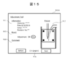
- FIG. 15 shows an example of the screen (step S119) of the adjustment completion report 910A.
- the screen of the adjustment completion report 910A includes, in addition to the display contents of the instruction screen 910 of FIG. 14, a switching button 916 for switching and displaying all the adjustment points on the device.
- FIG. 16 shows a first modification of the first embodiment.
- This first modification includes a second solenoid valve EV2 that opens and closes the waste liquid pipe 607 of the cleaning tank 606. By closing the second solenoid valve EV2, a certain amount of the cleaning liquid discharged from the flow path FP1 is stored in the cleaning tank 606, and the reagent dispensing mechanism 110 and the like are cleaned with the collected cleaning liquid.
- the suitability of the cleaning operation is determined by confirming with the measuring instrument SS whether the nozzle NZ1 sufficiently reaches the cleaning liquid accumulated in the cleaning tank 606. Can be done.
- FIG. 17 shows a second modification of the first embodiment.
- This second modification is different from the above embodiment in that the flow path FP1'has a configuration in which the flow path FP1'is connected to the lower part of the cleaning tank 606.
- the inflow amount of the cleaning liquid exceeds the amount of the waste liquid from the waste liquid pipe 607, and as in the first modification, the nozzle NZ1 of the reagent dispensing mechanism is inserted into the cleaning liquid collected in the cleaning tank 606. Perform cleaning.
- FIG. 18 shows a third modification of the first embodiment.
- the measuring instrument installation portion BX1a is provided on the upper part of the cleaning tank 606, and the measuring instrument SS, for example, the capacitance sensor SSsc can be suspended on the measuring instrument installation portion BX1. ..
- the cleaning tank 606 is used to perform cleaning with the cleaning liquid collected in the cleaning tank 606. Therefore, the capacitance sensor SSsc does not have to be a camera as long as it can measure the water level inside the cleaning tank 606.
- a non-contact ultrasonic sensor or an optical sensor may be adopted as the measuring instrument SS.
- the automatic analyzer 100 according to the second embodiment will be described with reference to FIG. Since the automatic analyzer 100 of the second embodiment has substantially the same overall configuration as that of the first embodiment (FIG. 1), duplicate description will be omitted.
- the difference from the first embodiment is that the measuring instrument installation unit BX is installed in the sample dispensing mechanism 117, and the dispensing operation is measured or photographed by the measuring instrument SS.
- the measuring instrument installation portion BX is provided in the vicinity of the cleaning mechanisms W1 to W5.
- the measuring instrument installation unit BX is installed in the vicinity of the position where the suction and discharge of the sample dispensing mechanism 117 are performed.
- FIG. 19 is a schematic plan view illustrating a configuration in the vicinity of the sample dispensing mechanism 117 of the second embodiment.
- the sample container rack 102 by the sample dispensing mechanism 117 is installed near the sample suction position 210, and Measuring instrument installation units BX42 and BX43 are also installed in the vicinity of the sample discharge position 211 of the incubator 108, respectively.
- the positions of the nozzles (for example, the nozzles of the sample dispensing mechanism 117 and the reagent dispensing mechanism 110) of the various processing units of the automatic analyzer 100 are relative to the reaction vessel 107 and the reagent vessel 104 in order to suck and discharge an accurate amount of liquid. It is necessary to adjust correctly in units of 0.1 m. Considering the tolerances of various parts, it is necessary to adjust the suction or discharge position of various nozzles in the xyz axis direction at the time of manufacturing or parts replacement. In addition, the suction position and the discharge position may change due to changes over time in the automatic analyzer.
- measuring instrument installation portions BX42 and BX43 are also provided at the liquid suction position and the discharge position by the nozzle of the sample dispensing mechanism 117. , Nozzle suction and discharge operation can be monitored. Moreover, the measuring instrument SS for monitoring can be shared among a plurality of processing units, and the manufacturing cost of the apparatus can be reduced.
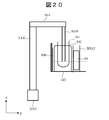
- FIG. 20 shows a specific configuration example (cross-sectional view) of the measuring instrument installation unit BX42.
- the measuring instrument installation portion BX42 is arranged at the sample suction position 210 of the nozzle NZ4 of the sample dispensing mechanism 117.
- the position of the nozzle NZ4 at the time of sample suction is adjusted by inserting the measuring instrument SS into the measuring instrument installation portion BX42 and photographing the background image plate 800.
- the position of the background image board 800 is not limited to a specific position, but it is preferable that the bottom surface of the rack transfer line 103 and the lower side of the background image board 800 substantially coincide with each other.
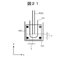
- FIG. 21 is an example of an image obtained by photographing the sample container 101 and the like with the measuring instrument SS inserted into the measuring instrument installation unit BX42.
- the distance a in the x-axis direction between the wall surface of the sample container 101 and the nozzle Nz4 and the distance b in the y-axis direction between the wall surface of the sample container 101 and the nozzle Nz4 (not shown).
- the distance c in the z-axis direction between the tip of the nozzle Nz4 and the bottom surface of the sample container 101 can be calculated with reference to the positioning mark on the background image plate 800.
- the storage unit 14 may store physical quantities representing the distances between the reference surface of the device and the rod-shaped member, such as the distance a, the distance b, and the distance c, as "predetermined reference".
- the reference surface of the device is the bottom surface or the side surface of the sample container 101.
- the automatic analyzer 100 according to the third embodiment will be described with reference to FIG. Since the automatic analyzer 100 of the third embodiment has substantially the same overall configuration as that of the first embodiment (FIG. 1), duplicate description will be omitted.
- the difference between the first embodiment and the third embodiment is the position where the measuring instrument installation unit BX is installed, as in the second embodiment.
- this third embodiment relates to the reagent dispensing mechanism 110.
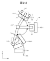
- FIG. 22 is a schematic plan view illustrating a configuration in the vicinity of the reagent dispensing mechanism 110 of the third embodiment.
- the reagent disk 106 by the reagent dispensing mechanism 110 is installed near the reagent suction position 310, and the incubator.
- Measuring instrument installation units BX43 and BX12 are also installed in the vicinity of the reagent discharge position 311 of 108, respectively.
- a sensor window (not shown) is provided on the side surface of the reagent disk 106 near the reagent suction position, and the measuring instrument SS arranged in the measuring instrument installation unit BX43 measures the inside of the reagent disk 106 through the sensor window. It is said to be observable.
- a sensor window (not shown) is provided on the side surface of the incubator 108 near the reagent discharge position, and the measuring instrument SS arranged in the measuring instrument installation portion BX12 measures the inside of the incubator 108 through the sensor window. Or it is observable.
- the measuring instrument installation portion BX is also provided at the suction position and the discharge position of the liquid by the nozzle of the reagent dispensing mechanism 110, and the nozzle is provided. It is possible to monitor the suction and discharge operations of the. Moreover, the measuring instrument SS for monitoring can be shared among a plurality of processing units, and the manufacturing cost of the apparatus can be reduced.
- the automatic analyzer 100 according to the fourth embodiment will be described with reference to FIG. 23. Since the automatic analyzer 100 of the fourth embodiment has substantially the same overall configuration as that of the first embodiment (FIG. 1), redundant description will be omitted. The difference between the first embodiment and the fourth embodiment is the position where the measuring instrument installation unit BX is installed, as in the second and third embodiments. However, this fourth embodiment relates to the stirring paddle drive mechanism 112.
- FIG. 23 is a schematic plan view illustrating a configuration in the vicinity of the stirring paddle drive mechanism 112 of the fourth embodiment.
- the measuring instrument installation unit BX2 in addition to (or instead) installing the measuring instrument installation unit BX2 in the vicinity of the cleaning mechanism W2 for the stirring paddle driving mechanism 112, in the vicinity of the stirring position 410 by the stirring paddle driving mechanism 112. Also, the measuring instrument installation unit BX21 is installed.
- a measuring instrument installation unit BX is also provided at the stirring position of the stirring paddle drive mechanism 112, and the stirring operation can be monitored. .. Moreover, the measuring instrument SS for monitoring can be shared among a plurality of processing units, and the manufacturing cost of the apparatus can be reduced.
- the automatic analyzer 100 according to the fifth embodiment will be described with reference to FIG. 24. Since the automatic analyzer 100 of the fifth embodiment has substantially the same overall configuration as that of the first embodiment (FIG. 1), duplicate description will be omitted. The difference between the first embodiment and the fifth embodiment is the position where the measuring instrument installation unit BX is installed, as in the second to fourth embodiments. However, this fifth embodiment relates to the reaction liquid suction mechanism 116.
- FIG. 24 is a schematic plan view illustrating a configuration in the vicinity of the reaction liquid suction mechanism 116 of the fifth embodiment.
- the measuring instrument installation unit BX31 in addition to (or replacing) the measuring instrument installation unit BX31 being installed in the vicinity of the cleaning mechanism W3 for the reaction liquid suction mechanism 116, the suction position 510 of the incubator 108 by the reaction liquid suction mechanism 116
- the measuring instrument installation unit BX31 is also installed in the vicinity of.
- the measuring instrument installation portion BX is also provided at the suction position of the reaction liquid by the nozzle of the reaction liquid suction mechanism 116, and the suction operation of the nozzle is performed. Can be monitored. Moreover, the measuring instrument SS for monitoring can be shared among a plurality of processing units, and the manufacturing cost of the apparatus can be reduced.
- the automatic analyzer 100 according to the sixth embodiment will be described with reference to FIG. 25. Since the automatic analyzer 100 of the sixth embodiment has substantially the same overall configuration as that of the first embodiment (FIG. 1), duplicate description will be omitted. The difference from the first embodiment is the position where the measuring instrument installation unit BX is installed in the sample dispensing mechanism 117. The sixth embodiment is common to the second embodiment in that the measuring instrument installation unit BX is installed even in the vicinity of the position where the suction and discharge of the sample dispensing mechanism 117 are performed.
- the measuring instrument installation unit BX4u capable of measuring or photographing from above the sample container 101 is provided.
- the measuring instrument SS installed in the measuring instrument installation unit BX42 photographs the background image plate 800A arranged on the side of the sample container rack 102, and the measuring instrument SS installed in the measuring instrument installation unit BX4u is the sample container rack.
- the background image board 800B arranged on the bottom surface side of 102 is photographed.
- FIG. 26 is an example of an image obtained by photographing the sample container 101 or the like from above with the measuring instrument SS inserted into the measuring instrument installation unit BX4u.
- the distance a in the x-axis direction between the wall surface of the sample container 101 and the nozzle Nz4 and the distance b in the y-axis direction between the wall surface of the sample container 101 and the nozzle Nz4 are shown as background images. It can be calculated with reference to the positioning mark on the plate 800B.
- the automatic analyzer 100 according to the seventh embodiment will be described with reference to FIG. 27. Since the automatic analyzer 100 of the seventh embodiment has substantially the same overall configuration as that of the first embodiment (FIG. 1), duplicate description will be omitted.
- This seventh embodiment is characterized by the configuration of the measuring instrument installation portion BX4 in the sample dispensing mechanism 117, and is common to the sixth embodiment (FIG. 20) in this respect.
- the sample dispensing mechanism 117 serves as the measuring instrument installation unit BX4, the measuring instrument accommodating portion 701 for adjusting the height of the measuring instrument (camera), and the measuring instrument. It includes an optical element 220 (for example, a mirror, a prism, a light guide, etc.) that changes the optical path of the SS, and an optical element mounting portion 221 that fixes the optical element 220.
- the measuring instrument accommodating portion 701 the measuring instrument SS can be held at a position higher than that of the sample container 101.
- the optical element 220 the sample container 101 can be observed from the measuring instrument SS at a high position. According to this configuration, the sample container 101 can be photographed even when there is no place to provide the measuring instrument installation portion in the vicinity of the sample dispensing mechanism 117.
- the automatic analyzer 100 according to the eighth embodiment will be described with reference to FIGS. 28 and 29. Since the automatic analyzer 100 of the eighth embodiment has substantially the same overall configuration as that of the first embodiment (FIG. 1), duplicate description will be omitted.
- This eighth embodiment is common to the third embodiment in that it is configured to measure or photograph the reagent dispensing operation in the reagent dispensing mechanism 110.
- the measuring instrument SS for measuring or photographing the reagent suction operation from the reagent disk 106 can be inserted into the reagent container storage portion of the reagent disk 106. That is, in the eighth embodiment, the reagent container storage unit also serves as the above-mentioned measuring instrument installation unit.
- FIG. 28 illustrates the cross-sectional structure of a general reagent disc 106 for comparison.
- the automatic analyzer 100 usually includes a plurality of reagent containers (104a, 104b %) And a plurality of reagent container storage units (126a, 126b ”) In the reagent disk 106 in order to measure a plurality of measurement items. It has a configuration in which the reagent container and the reagent container storage portion can be moved to the reagent dispensing position.
- a sensor window is provided on the outer periphery of the reagent disk 106, and a measuring instrument is arranged on the outer periphery of the reagent disk 106 through the sensor window to monitor the suction operation of the reagent. It is possible. However, the reagent disc 106 is usually covered with a thick heat insulating material on its outer circumference. Therefore, it may be difficult to arrange the measuring instrument SS on the side surface of the reagent disk 106 via the sensor window 3.
- FIG. 29 shows the cross-sectional structure of the reagent disk 106 in the eighth embodiment.
- the measuring instrument installation unit BX1 is prepared in one of the reagent container storage units (for example, 126b) in the reagent disk 106. That is, the reagent container storage unit 126b also serves as the measuring instrument installation unit BX1.
- a sensor window 703 is provided between the reagent container storage unit 126b that also serves as the measuring instrument installation unit BX1 and the reagent container storage unit 126a that is the measurement target. Further, a background image board 800 similar to the above-described embodiment is provided on the side surface opposite to the measuring instrument installation portion BX1. Further, below the reagent container storage unit 126b, a measuring instrument sensor 704 similar to the above-described embodiment is provided.
- FIG. 30 shows the dispensing mechanism 110, the stirring paddle drive mechanism 112, the reaction liquid suction mechanism 116 (116a, 116b), the sample dispensing mechanism 117, the BF separation mechanism 118, and the like in the second to eighth embodiments. It is a flowchart in the case of performing an operation of adjusting the position of a rod-shaped member such as various nozzles and a paddle for stirring (in FIG. 30, it is described assuming that the nozzle is a control target). The operation of this flowchart is executed according to the automatic adjustment tool stored in the storage unit 14.
- Steps S100 to 105 in FIG. 30 are the same as those in the first embodiment, and therefore duplicate description will be omitted.
- the control unit 11 moves the nozzle to a predetermined suction / discharge position (step S201).
- step S202 When the nozzle moves to a predetermined suction / discharge position, the nozzle and the background image plate 800 are photographed by the measuring instrument SS (step S202).
- the control unit 11 determines from the background image board 800 whether or not the captured image is along the x-axis and z-axis directions (step S203). If the judgment in step S203 is affirmative (YES), the control unit 11 calculates the position of the nozzle, and the position of the nozzle is within the range of the "predetermined reference" in the x-axis direction and the z-axis direction. It is determined whether or not there is (step S204).
- control unit 11 determines whether or not the captured image is an image along the x-axis and the y-axis (step S206). If the determination is affirmative (YES), the y-axis operation pulse is changed in the same manner as in step S205 (step S208).
- the control unit 11 moves the nozzle to the initial position and issues an instruction to remove the measuring instrument SS from the measuring instrument installation unit 201 (step S209).
- the number of adjustment execution times i is a predetermined number n or less, 1 is added to the adjustment execution number i.
- S201 to S209 are repeated until the number of adjustments i is n.
- step S210 When the number of adjustments i reaches n (YES in step S210), S116 to S120 similar to the process described in FIG. 12 are executed to end the operation.
- the flowchart shown in FIG. 28 may be combined with the flowchart for adjusting the cleaning mechanisms W1 to W5 of FIG. 12 according to the first embodiment.
- the present invention is not limited to the above-described embodiment, and includes various modifications.
- the above-described embodiment has been described in detail in order to explain the present invention in an easy-to-understand manner, and is not necessarily limited to those having all the described configurations.
- it is possible to replace a part of the configuration of one embodiment with the configuration of another embodiment and it is also possible to add the configuration of another embodiment to the configuration of one embodiment.
- 100 ... Automatic analyzer 100A ... Main unit, 11 ... Control unit, 12 ... Input unit, 13 ... Display unit, 14 ... Storage unit, 15 ... External control unit, 101 ... Specimen container, 102 ... Specimen container rack, 103 ... Rack transfer line, 104 ... reagent container, 105 ... reagent disk cover, 106 ... reagent disk, 107 ... reaction vessel, 108 ... incubator, W1 to W5 ... cleaning mechanism, 110 ... reagent dispensing mechanism, 112 ... stirring paddle drive mechanism, 115 ... Detection mechanism, 116 ... Reagent suction mechanism, 117 ... Sample dispensing mechanism, BX1-5 ... Measuring instrument installation part, SF1-5 ... Shaft, AX1-5 ... Rotating shaft, SS ... Measuring instrument.
Landscapes
- Chemical & Material Sciences (AREA)
- General Health & Medical Sciences (AREA)
- Life Sciences & Earth Sciences (AREA)
- Health & Medical Sciences (AREA)
- Analytical Chemistry (AREA)
- Biochemistry (AREA)
- Physics & Mathematics (AREA)
- General Physics & Mathematics (AREA)
- Immunology (AREA)
- Pathology (AREA)
- Engineering & Computer Science (AREA)
- Quality & Reliability (AREA)
- Chemical Kinetics & Catalysis (AREA)
- Automatic Analysis And Handling Materials Therefor (AREA)
Abstract
Description
図1は、第1の実施の形態に係る自動分析装置100の概略構成図である。図1に示すように、自動分析装置100は、本体部100Aと、制御部11、入力部12、表示部13、記憶部14、及び外部制御部15を備えている。
(式1) 画素分解能=Y方向視野サイズ(mm)÷CCDのy方向画素数
図16は、第1の実施の形態の第1の変形例を示す。この第1の変形例は、洗浄槽606の廃液管607を開閉する第2電磁弁EV2を備えている。第2電磁弁EV2を閉じることで流路FP1から吐出された洗浄液を洗浄槽606に一定量溜め、溜まった洗浄液で試薬分注機構110等を洗浄する。この第1の変形例の場合、図12のS108において、測定器SSにより、洗浄槽606に溜まった洗浄液にノズルNZ1が十分到達しているかを確認することにより、洗浄動作の適否を判断することができる。
次に、第2の実施の形態に係る自動分析装置100を、図19を参照して説明する。第2の実施の形態の自動分析装置100は、全体構成としては第1の実施の形態(図1)と略同一であるため、重複する説明は省略する。第1の実施の形態との相違点は、試料分注機構117において測定器設置部BXが設置され、分注動作が測定器SSにより測定又は撮影される点である。
ここで、装置の基準面とは検体容器101の底面や側面とする。
次に、第3の実施の形態に係る自動分析装置100を、図22を参照して説明する。第3の実施の形態の自動分析装置100は、全体構成としては第1の実施の形態(図1)と略同一であるため、重複する説明は省略する。第1の実施の形態と第3の実施の形態との相違点は、第2の実施の形態と同じく、測定器設置部BXが設置される位置である。ただし、この第3の実施の形態は、試薬分注機構110に関する。
次に、第4の実施の形態に係る自動分析装置100を、図23を参照して説明する。第4の実施の形態の自動分析装置100は、全体構成としては第1の実施の形態(図1)と略同一であるため、重複する説明は省略する。第1の実施の形態と第4の実施の形態との相違点は、第2及び第3の実施の形態と同じく、測定器設置部BXが設置される位置である。ただし、この第4の実施の形態は、撹拌パドル駆動機構112に関する。
次に、第5の実施の形態に係る自動分析装置100を、図24を参照して説明する。第5の実施の形態の自動分析装置100は、全体構成としては第1の実施の形態(図1)と略同一であるため、重複する説明は省略する。第1の実施の形態と第5の実施の形態との相違点は、第2~第4の実施の形態と同じく、測定器設置部BXが設置される位置である。ただし、この第5の実施の形態は、反応液吸引機構116に関する。
次に、第6の実施の形態に係る自動分析装置100を、図25を参照して説明する。第6の実施の形態の自動分析装置100は、全体構成としては第1の実施の形態(図1)と略同一であるため、重複する説明は省略する。第1の実施の形態との相違点は、試料分注機構117において測定器設置部BXが設置される位置である。第6の実施の形態は、試料分注機構117の吸引及び吐出が行われる位置の近傍においても測定器設置部BXが設置される点において、第2の実施の形態と共通している。ただし、この第6の実施の形態では、検体容器101を横方向から測定又は撮影可能とする測定器設置部BX42に加え、検体容器101上方から測定又は撮影可能とした測定器設置部BX4uが設けられている。測定器設置部BX42に設置された測定器SSは、検体容器ラック102の側部に配置された背景画像板800Aを撮影し、測定器設置部BX4uに設置された測定器SSは、検体容器ラック102の底面側に配置された背景画像板800Bを撮影する。
次に、第7の実施の形態に係る自動分析装置100を、図27を参照して説明する。第7の実施の形態の自動分析装置100は、全体構成としては第1の実施の形態(図1)と略同一であるため、重複する説明は省略する。この第7の実施の形態は、試料分注機構117における測定器設置部BX4の構成に特徴を有しており、この点で第6の実施の形態(図20)と共通している。
次に、第8の実施の形態に係る自動分析装置100を、図28及び図29を参照して説明する。第8の実施の形態の自動分析装置100は、全体構成としては第1の実施の形態(図1)と略同一であるため、重複する説明は省略する。この第8の実施の形態は、試薬分注機構110における試薬分注動作を測定又は撮影するよう構成されている点で、第3の実施の形態と共通する。ただし、この第8の実施の形態では、試薬ディスク106からの試薬吸引動作を測定又は撮影するための測定器SSを、試薬ディスク106の試薬容器収納部に挿入可能としている。すなわち、この第8の実施の形態では、試薬容器収納部が前述の測定器設置部を兼ねている。
図30は、第2~第8の実施の形態において、分注機構110、撹拌パドル駆動機構112、反応液吸引機構116(116a、116b)、試料分注機構117、BF分離機構118などにおいて、各種ノズルや撹拌用のパドルなどの棒状部材の位置の調整を行う動作を行う場合におけるフローチャートである(図30では、ノズルが制御対象であるとして説明を行う)。このフローチャートの動作は、記憶部14に保存されている自動調整ツールに従って実行される。
(式2) (調整パルス数pulse)={(設計値a1 mm)-(測定器SSによって観察されたx軸の距離a mm)}}÷1パルス当たりの駆動(mm/pulse)
Claims (14)
- 分析に係る動作を実行する複数の処理部と、
前記複数の処理部の各々に配置され、前記複数の処理部の動作を測定する測定器を設置可能に構成された複数の測定器設置部と、
前記複数の処理部を制御する制御部と
を備え、
前記複数の測定器設置部の各々は、前記測定器を取り外し可能に構成され、取り外された前記測定器を他の測定器設置部に設置可能に構成される、自動分析装置。 - 前記測定器により得られた前記動作の測定結果を表示する表示部を備える、
請求項1に記載の自動分析装置。 - 前記制御部は、前記測定結果に基づき、前記動作が予め定められた基準内であるか否かを判断する、
請求項2に記載の自動分析装置。 - 前記制御部は、前記動作が予め定められた基準内であるか否かを判断した結果に基づき、前記処理部の動作を変更する、
請求項3に記載の自動分析装置。 - 前記処理部は、液体に接触する棒状部材を有する、請求項1に記載の自動分析装置。
- 前記測定器設置部は、前記測定器が前記棒状部材の停止位置を測定可能となるように配置される、請求項5に記載の自動分析装置。
- 前記複数の処理部は、前記棒状部材を洗浄する洗浄機構を含み、
前記測定器は、前記洗浄機構による洗浄液を測定する、
請求項5に記載の自動分析装置。 - 前記測定器は、前記棒状部材の停止位置と前記自動分析装置の基準面との距離を計測する、請求項6に記載の自動分析装置。
- 前記測定器は、レンズと画像素子を有し、前記動作を撮像可能である、
請求項1に記載の自動分析装置。 - 前記測定器は、前記洗浄機構の洗浄液の液量を測定する、請求項7に記載の自動分析装置。
- 前記複数の測定器設置部を識別するための識別ラベルを備える、請求項1に記載の自動分析装置。
- 前記複数の測定器設置部の中から、前記測定器を設置すべき測定器設置部を表示する表示部を備える、請求項1に記載の自動分析装置。
- 前記レンズの撮影対象を挟んで、該レンズの反対側に配置される背景画像板を備える、請求項9に記載の自動分析装置。
- 前記背景画像板は、位置決めマーク、又は、機械可読テキストである、請求項13に記載の自動分析装置。
Priority Applications (4)
| Application Number | Priority Date | Filing Date | Title |
|---|---|---|---|
| US17/792,586 US20230067353A1 (en) | 2020-01-16 | 2020-12-09 | Automatic Analyzer |
| EP20913111.9A EP4092419B1 (en) | 2020-01-16 | 2020-12-09 | Automated analyzer |
| JP2021570684A JP7353392B2 (ja) | 2020-01-16 | 2020-12-09 | 自動分析装置 |
| CN202080090795.3A CN114868022A (zh) | 2020-01-16 | 2020-12-09 | 自动分析装置 |
Applications Claiming Priority (2)
| Application Number | Priority Date | Filing Date | Title |
|---|---|---|---|
| JP2020-005439 | 2020-01-16 | ||
| JP2020005439 | 2020-01-16 |
Publications (1)
| Publication Number | Publication Date |
|---|---|
| WO2021145108A1 true WO2021145108A1 (ja) | 2021-07-22 |
Family
ID=76864161
Family Applications (1)
| Application Number | Title | Priority Date | Filing Date |
|---|---|---|---|
| PCT/JP2020/045937 Ceased WO2021145108A1 (ja) | 2020-01-16 | 2020-12-09 | 自動分析装置 |
Country Status (5)
| Country | Link |
|---|---|
| US (1) | US20230067353A1 (ja) |
| EP (1) | EP4092419B1 (ja) |
| JP (1) | JP7353392B2 (ja) |
| CN (1) | CN114868022A (ja) |
| WO (1) | WO2021145108A1 (ja) |
Cited By (2)
| Publication number | Priority date | Publication date | Assignee | Title |
|---|---|---|---|---|
| WO2023176401A1 (ja) * | 2022-03-17 | 2023-09-21 | 富士フイルム株式会社 | 検査装置 |
| WO2024190197A1 (ja) * | 2023-03-15 | 2024-09-19 | 株式会社日立ハイテク | 自動分析装置 |
Citations (3)
| Publication number | Priority date | Publication date | Assignee | Title |
|---|---|---|---|---|
| KR20040006954A (ko) * | 2002-07-16 | 2004-01-24 | 학교법인 한양학원 | 다용도 주사전기 탐침시스템 및 이를 이용한 탐침방법 |
| KR20110104281A (ko) * | 2010-03-16 | 2011-09-22 | 대윤계기산업 주식회사 | 카드형 멀티측정기 |
| JP2017151002A (ja) | 2016-02-25 | 2017-08-31 | 株式会社日立ハイテクノロジーズ | 自動分析装置 |
Family Cites Families (24)
| Publication number | Priority date | Publication date | Assignee | Title |
|---|---|---|---|---|
| US4951512A (en) * | 1988-06-23 | 1990-08-28 | Baxter International Inc. | System for providing access to sealed containers |
| JP2004151025A (ja) * | 2002-10-31 | 2004-05-27 | Teruaki Ito | 試験管種類判別装置 |
| US7186378B2 (en) * | 2003-07-18 | 2007-03-06 | Dade Behring Inc. | Liquid sampling probe and cleaning fluidics system |
| JP4464982B2 (ja) * | 2007-03-30 | 2010-05-19 | 株式会社日立ハイテクノロジーズ | 自動分析装置 |
| US20090114538A1 (en) * | 2007-11-07 | 2009-05-07 | Takayama Hiroko | Automated biochemical analyzer |
| US8726745B2 (en) * | 2007-11-26 | 2014-05-20 | Perkinelmer Health Sciences, Inc. | Fluid handling device with ultrasound sensor and methods and systems using same |
| JP2009181328A (ja) * | 2008-01-30 | 2009-08-13 | Olympus Corp | 管理システム |
| BE1018834A3 (nl) * | 2009-07-21 | 2011-09-06 | Praet Peter Van | Inspectie camera gemonteerd op een medische diagnose automaat. |
| JP5452214B2 (ja) * | 2009-12-25 | 2014-03-26 | 株式会社日立ハイテクノロジーズ | 遺伝子検査装置 |
| JP5417262B2 (ja) * | 2010-06-08 | 2014-02-12 | 株式会社エスアールエル | 検体認識装置 |
| JP5492676B2 (ja) * | 2010-06-28 | 2014-05-14 | 株式会社日立ハイテクノロジーズ | 自動分析装置 |
| JP2013064673A (ja) * | 2011-09-20 | 2013-04-11 | Hitachi High-Technologies Corp | 自動分析装置 |
| US9810704B2 (en) * | 2013-02-18 | 2017-11-07 | Theranos, Inc. | Systems and methods for multi-analysis |
| EP2796882B1 (en) * | 2011-12-22 | 2023-03-29 | Hitachi High-Tech Corporation | Automatic analysis device |
| WO2013122013A1 (ja) * | 2012-02-16 | 2013-08-22 | 株式会社日立ハイテクノロジーズ | 自動分析装置の調整システム、及び自動分析装置の調整方法 |
| JP6333584B2 (ja) * | 2014-03-11 | 2018-05-30 | キヤノンメディカルシステムズ株式会社 | 臨床検査装置 |
| JP2016161301A (ja) * | 2015-02-27 | 2016-09-05 | 株式会社日立ハイテクノロジーズ | 検体検査自動化システム |
| US10086368B2 (en) * | 2015-09-07 | 2018-10-02 | EXIAS Medical GmbH | Movable measurement cell |
| JP2017116745A (ja) * | 2015-12-24 | 2017-06-29 | キヤノン株式会社 | 画像形成装置および制御方法 |
| JP7030056B2 (ja) * | 2016-01-28 | 2022-03-04 | シーメンス・ヘルスケア・ダイアグノスティックス・インコーポレーテッド | 試料容器と試料の特徴付けのための方法及び装置 |
| JP6745459B2 (ja) * | 2016-07-19 | 2020-08-26 | パナソニックIpマネジメント株式会社 | 水分量観察装置、水分量観察方法及び栽培装置 |
| WO2018042915A1 (ja) * | 2016-09-05 | 2018-03-08 | 株式会社日立ハイテクノロジーズ | 診断デバイス |
| JP6887880B2 (ja) * | 2017-05-30 | 2021-06-16 | 日本電子株式会社 | 自動分析装置及びプログラム |
| CN111201440B (zh) * | 2017-10-10 | 2021-04-20 | 株式会社日立高新技术 | 自动分析装置 |
-
2020
- 2020-12-09 JP JP2021570684A patent/JP7353392B2/ja active Active
- 2020-12-09 US US17/792,586 patent/US20230067353A1/en active Pending
- 2020-12-09 WO PCT/JP2020/045937 patent/WO2021145108A1/ja not_active Ceased
- 2020-12-09 EP EP20913111.9A patent/EP4092419B1/en active Active
- 2020-12-09 CN CN202080090795.3A patent/CN114868022A/zh active Pending
Patent Citations (3)
| Publication number | Priority date | Publication date | Assignee | Title |
|---|---|---|---|---|
| KR20040006954A (ko) * | 2002-07-16 | 2004-01-24 | 학교법인 한양학원 | 다용도 주사전기 탐침시스템 및 이를 이용한 탐침방법 |
| KR20110104281A (ko) * | 2010-03-16 | 2011-09-22 | 대윤계기산업 주식회사 | 카드형 멀티측정기 |
| JP2017151002A (ja) | 2016-02-25 | 2017-08-31 | 株式会社日立ハイテクノロジーズ | 自動分析装置 |
Non-Patent Citations (1)
| Title |
|---|
| See also references of EP4092419A4 |
Cited By (3)
| Publication number | Priority date | Publication date | Assignee | Title |
|---|---|---|---|---|
| WO2023176401A1 (ja) * | 2022-03-17 | 2023-09-21 | 富士フイルム株式会社 | 検査装置 |
| EP4495605A4 (en) * | 2022-03-17 | 2025-07-16 | Fujifilm Corp | TEST DEVICE |
| WO2024190197A1 (ja) * | 2023-03-15 | 2024-09-19 | 株式会社日立ハイテク | 自動分析装置 |
Also Published As
| Publication number | Publication date |
|---|---|
| CN114868022A (zh) | 2022-08-05 |
| EP4092419B1 (en) | 2026-03-18 |
| EP4092419A1 (en) | 2022-11-23 |
| US20230067353A1 (en) | 2023-03-02 |
| JPWO2021145108A1 (ja) | 2021-07-22 |
| JP7353392B2 (ja) | 2023-09-29 |
| EP4092419A4 (en) | 2024-01-17 |
Similar Documents
| Publication | Publication Date | Title |
|---|---|---|
| EP2040081B1 (en) | Sample analyzer and error information displaying method | |
| CN101526542B (zh) | 标本分析仪及其控制系统 | |
| EP1589344A1 (en) | Monitoring function-equipped dispensing system and method of monitoring dispensing device | |
| JP4949389B2 (ja) | 自動分析装置 | |
| EP2479560A1 (en) | Automatic analyzing device | |
| CN115144602A (zh) | 自动分析装置以及自动分析方法 | |
| JP2010175420A (ja) | 試料分析装置 | |
| JP7353392B2 (ja) | 自動分析装置 | |
| EP2019321A1 (en) | Cleaning equipment and automatic analyzer | |
| CN111742226A (zh) | 自动分析装置 | |
| JP2015087265A (ja) | 自動分析装置 | |
| EP4354150A1 (en) | Automatic analysis device | |
| CN103293329B (zh) | 自动分析装置 | |
| JP5129281B2 (ja) | 遠隔管理システム | |
| US11933804B2 (en) | Automatic analyzer | |
| JP6433859B2 (ja) | 自動分析装置 | |
| JPWO2015198707A1 (ja) | 検体検査自動化システムおよび検体チェックモジュール | |
| US20130121882A1 (en) | Dispensing device and nucleic acid analyzer | |
| JP4843456B2 (ja) | 自動分析装置及びその判定方法 | |
| JP2006138654A (ja) | 有形成分分析装置および有形成分分析方法 | |
| JP4237021B2 (ja) | 自動分析装置 | |
| EP3786644B1 (en) | Automated analyzer and method of controlling the automated analyzer | |
| JP5722406B2 (ja) | 検体分析装置 | |
| JP2023127333A (ja) | 自動分析装置、プログラム、および記憶媒体、並びに方法 | |
| US12571808B2 (en) | Systems and methods for automated grossing of tissue samples |
Legal Events
| Date | Code | Title | Description |
|---|---|---|---|
| 121 | Ep: the epo has been informed by wipo that ep was designated in this application |
Ref document number: 20913111 Country of ref document: EP Kind code of ref document: A1 |
|
| ENP | Entry into the national phase |
Ref document number: 2021570684 Country of ref document: JP Kind code of ref document: A |
|
| NENP | Non-entry into the national phase |
Ref country code: DE |
|
| ENP | Entry into the national phase |
Ref document number: 2020913111 Country of ref document: EP Effective date: 20220816 |
|
| WWG | Wipo information: grant in national office |
Ref document number: 2020913111 Country of ref document: EP |