WO2021145162A1 - Raccord fileté pour tuyau - Google Patents
Raccord fileté pour tuyau Download PDFInfo
- Publication number
- WO2021145162A1 WO2021145162A1 PCT/JP2020/047836 JP2020047836W WO2021145162A1 WO 2021145162 A1 WO2021145162 A1 WO 2021145162A1 JP 2020047836 W JP2020047836 W JP 2020047836W WO 2021145162 A1 WO2021145162 A1 WO 2021145162A1
- Authority
- WO
- WIPO (PCT)
- Prior art keywords
- pin
- box
- shoulder
- intermediate shoulder
- male screw
- Prior art date
- Legal status (The legal status is an assumption and is not a legal conclusion. Google has not performed a legal analysis and makes no representation as to the accuracy of the status listed.)
- Ceased
Links
Images


Classifications
-
- F—MECHANICAL ENGINEERING; LIGHTING; HEATING; WEAPONS; BLASTING
- F16—ENGINEERING ELEMENTS AND UNITS; GENERAL MEASURES FOR PRODUCING AND MAINTAINING EFFECTIVE FUNCTIONING OF MACHINES OR INSTALLATIONS; THERMAL INSULATION IN GENERAL
- F16L—PIPES; JOINTS OR FITTINGS FOR PIPES; SUPPORTS FOR PIPES, CABLES OR PROTECTIVE TUBING; MEANS FOR THERMAL INSULATION IN GENERAL
- F16L15/00—Screw-threaded joints; Forms of screw-threads for such joints
- F16L15/006—Screw-threaded joints; Forms of screw-threads for such joints with straight threads
- F16L15/007—Screw-threaded joints; Forms of screw-threads for such joints with straight threads with more than one threaded section
-
- F—MECHANICAL ENGINEERING; LIGHTING; HEATING; WEAPONS; BLASTING
- F16—ENGINEERING ELEMENTS AND UNITS; GENERAL MEASURES FOR PRODUCING AND MAINTAINING EFFECTIVE FUNCTIONING OF MACHINES OR INSTALLATIONS; THERMAL INSULATION IN GENERAL
- F16L—PIPES; JOINTS OR FITTINGS FOR PIPES; SUPPORTS FOR PIPES, CABLES OR PROTECTIVE TUBING; MEANS FOR THERMAL INSULATION IN GENERAL
- F16L15/00—Screw-threaded joints; Forms of screw-threads for such joints
- F16L15/001—Screw-threaded joints; Forms of screw-threads for such joints with conical threads
- F16L15/002—Screw-threaded joints; Forms of screw-threads for such joints with conical threads with more than one threaded section
-
- E—FIXED CONSTRUCTIONS
- E21—EARTH OR ROCK DRILLING; MINING
- E21B—EARTH OR ROCK DRILLING; OBTAINING OIL, GAS, WATER, SOLUBLE OR MELTABLE MATERIALS OR A SLURRY OF MINERALS FROM WELLS
- E21B17/00—Drilling rods or pipes; Flexible drill strings; Kellies; Drill collars; Sucker rods; Cables; Casings; Tubings
- E21B17/02—Couplings; joints
- E21B17/04—Couplings; joints between rod or the like and bit or between rod and rod or the like
- E21B17/042—Threaded
- E21B17/0423—Threaded with plural threaded sections, e.g. with two-step threads
-
- F—MECHANICAL ENGINEERING; LIGHTING; HEATING; WEAPONS; BLASTING
- F16—ENGINEERING ELEMENTS AND UNITS; GENERAL MEASURES FOR PRODUCING AND MAINTAINING EFFECTIVE FUNCTIONING OF MACHINES OR INSTALLATIONS; THERMAL INSULATION IN GENERAL
- F16L—PIPES; JOINTS OR FITTINGS FOR PIPES; SUPPORTS FOR PIPES, CABLES OR PROTECTIVE TUBING; MEANS FOR THERMAL INSULATION IN GENERAL
- F16L15/00—Screw-threaded joints; Forms of screw-threads for such joints
- F16L15/001—Screw-threaded joints; Forms of screw-threads for such joints with conical threads
- F16L15/004—Screw-threaded joints; Forms of screw-threads for such joints with conical threads with axial sealings having at least one plastically deformable sealing surface
Definitions
- This disclosure relates to threaded joints for pipes used for connecting steel pipes and the like.
- oil wells In oil wells, natural gas wells, etc. (hereinafter collectively referred to as "oil wells"), in order to mine underground resources, casings for constructing multiple well walls and oil and gas placed in the casings.
- the tubing that produces the is used.
- These casings and tubing are formed by sequentially connecting a large number of steel pipes, and a threaded pipe joint is used for the connection.
- Steel pipes used in oil wells are also called oil well pipes.
- Integral type threaded pipe joints are disclosed in, for example, Patent Documents 1 and 2 below, and coupling type threaded pipe joints are disclosed, for example, in Patent Document 3 below.
- the well pipes are directly connected to each other. Specifically, a female threaded portion is provided at one end of the well pipe, and a male threaded portion is provided at the other end. By screwing the male threaded portion of another oil well pipe into the female threaded portion of one well pipe, the oil well pipes are connected to each other. Be connected.
- the well pipes are connected to each other via a tubular coupling.
- female threaded portions are provided at both ends of the coupling
- male threaded portions are provided at both ends of the well pipe. Then, one male threaded portion of one oil well pipe is screwed into one female threaded portion of the coupling, and one male threaded portion of the other oil well pipe is screwed into the other female threaded portion of the coupling to form the coupling.
- the oil well pipes are connected to each other via. That is, in the coupling type, one of the pair of directly connected pipe materials is an oil well pipe, and the other is a coupling.
- the end of the well pipe on which the male thread portion is formed is called a pin because it contains an element to be inserted into the female thread portion formed on the oil well pipe or the coupling.
- the end of the well pipe or coupling on which the female thread is formed is referred to as a box because it contains an element that accepts the male thread formed at the end of the well.
- Threaded joints may be used.
- a threaded joint whose box outer diameter is approximately equal to the outer diameter of the pipe body of the oil country tubular goods pipe is also called a flush type threaded joint.
- a threaded joint having a box outer diameter of less than approximately 108% of the outer diameter of the pipe body of the oil country tubular goods pipe is also referred to as a semi-flash type threaded joint.
- these flush-type and semi-flash-type threaded joints required to have high strength and sealing performance, but also because the threaded structure and the sealing structure are arranged within a limited pipe wall thickness, each part is strict. Dimensional restrictions are imposed.
- a joint design is adopted in which male and female threads are composed of two-step threads in which an intermediate shoulder is provided in the middle of the joint in the axial direction and threads are arranged before and after the intermediate shoulder. Often done.
- a threaded joint having a two-step screw structure as disclosed in Patent Documents 1 and 2, in order to secure the sealing performance against the internal pressure and the sealing performance against the external pressure under strict dimensional restrictions, in the vicinity of the pin tip portion.
- An internal pressure seal is provided, and an external pressure seal is provided near the end of the box opening.
- Patent Documents 1 and 2 are applications filed by the applicants of the present application, and the drawings attached to these applications are schematic views for explaining the features of each invention in an easy-to-understand manner, and are related to the features.
- the dimensions of each part are not accurate. Therefore, it should be added that technical features not explicitly disclosed in the specification should not be extracted from the drawing dimensions of the parts not described in the specification of these applications.
- the stubing guide is attached to the open end of the box and then the pins are stabbed. Therefore, the outer box sealing surface (external pressure box sealing surface) provided near the box opening end is stunned. It is protected by the bing guide and is less likely to be damaged by the impact of the pin intermediate shoulder. On the other hand, even if the stubing guide is used, there is a risk that the sealing surface inside the pin comes into contact with the box intermediate shoulder.
- the environment in which oil country tubular goods is used is higher than the external pressure, so the external pressure is sealed with the external seal, while the internal pressure is sealed with the internal seal. It is important to avoid it.
- the purpose of the present disclosure is to prevent the box intermediate shoulder from hitting the inner seal surface of the pin during stubing in a threaded joint for a pipe having a two-stage thread structure, and to prevent the inner pin seal from being scratched.
- the threaded pipe joint according to the present disclosure is composed of a tubular pin and a tubular box, and the pin is screwed into the box to fasten the pin and the box.
- the pin is provided between the first male screw, the second male screw provided on the tip side of the first male screw and having a diameter smaller than that of the first male screw, and between the first male screw and the second male screw. It includes a pin intermediate shoulder, an inner pin sealing surface provided on the tip side of the second male screw, and an outer pin sealing surface provided on the proximal end side of the first male screw.
- the box is provided between the first female screw to which the first male screw fits in the fastened state, the second female screw to which the second male screw fits in the fastened state, and the first female screw and the second female screw.
- a box intermediate shoulder that contacts the pin intermediate shoulder in the fastened state, a box inner seal surface that contacts the pin inner seal surface in the fastened state, and a box outer seal surface that contacts the pin outer seal surface in the fastened state.
- the threaded pipe joint according to the present disclosure satisfies the following formulas (1) and (2).
- L P is the axial distance between said pin intermediate the shoulder side end portions and the radially outer end of the pin intermediate the shoulder of the pin within the sealing surface
- L B is the box intermediate the box outer sealing surfaces
- h P is the radial outer end of the pin intermediate shoulder and the pin intermediate shoulder on the pin inner sealing surface.
- the radial distance between the box, h B is the radial distance between the box intermediate shoulder side end of the box outer seal surface and the radial inner end of the box intermediate shoulder
- ⁇ seal is the pin inner seal.
- the gradient angle ⁇ P of a straight line connecting the end of the inner seal surface on the pin intermediate shoulder side and the radial outer end of the pin intermediate shoulder is on the box intermediate shoulder side of the outer box seal surface. It is larger than the gradient angle ⁇ B of the straight line connecting the end portion and the radial inner end of the box intermediate shoulder. More preferably, the gradient angle ⁇ P is less than 6 °.
- L P is larger than 94% of L B
- the present disclosure is particularly useful.
- h B is larger than h P, it is possible to avoid damage to the seal point SP, which has the largest seal contact pressure among the seal surfaces in the pin, and the diameter of h B. Since there is a design margin for the first female screw 31 provided within the direction range and the corresponding first male screw 21, this margin can be allocated to various performances.
- the seal point SP which has the highest seal contact force due to contact with the box inner seal surface among the pin inner seal surfaces at the completion of fastening, and the pin intermediate between the pin inner seal surfaces.
- the axial distance L SP between the end P 1 of the shoulder side is preferably smaller than the difference between L B and L P.
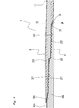
- FIG. 1 is a vertical cross-sectional view of a threaded pipe joint according to an embodiment.
- FIG. 2 is a dimensional explanatory view of the characteristic portion of the pin and the box.
- FIG. 3 is an enlarged view of the vicinity of the pin tip portion.
- FIG. 4 is a cross-sectional view for explaining a state at the time of stabbing.
- the threaded pipe joint 1 is composed of a tubular pin 2 and a tubular box 3.
- the pin 2 and the box 3 are fastened by screwing the pin 2 into the box 3.
- the pin 2 is provided at the end of the first pipe P1, and the box 3 is provided at the end of the second pipe P2.
- the first pipe P1 may be a long pipe such as an oil well pipe.
- the second pipe may be a coupling for connecting the long pipes to each other, but is preferably a long pipe such as an oil well pipe. That is, the threaded pipe joint 1 according to the present embodiment is preferably an integral type threaded pipe joint.
- the well pipe and the coupling are typically made of steel, but may be made of a metal such as stainless steel or a nickel-based alloy.
- the pin 2 may be formed at one end of the first oil country tubular goods P1 that has been reduced in diameter.
- the box 3 may be formed at one end of the second oil country tubular goods P2 that has been expanded in diameter.
- the pin 2 can be formed at one end of each well pipe P1 and P2, and the box 3 can be formed at the other end. More specifically, in the first oil well pipe P1, one end of a raw pipe made of a long pipe is reduced in diameter, and then the outer circumference of the reduced diameter end is formed as a component of a pin 2. It can be manufactured by cutting.
- one end of a raw pipe made of a long pipe is expanded in diameter, and then the inner circumference of the expanded end is cut so as to form a component of the box 3.
- the wall thickness of the pin 2 and the box 3 can be secured in the semi-flash type integral type threaded joint.
- the portion of the oil country tubular goods P1 and P2 other than the pin 2 and the box 3 that has not been reduced in diameter or expanded in diameter is referred to as a “pipe body”.
- the tube end side of the pin 2 means a direction from the tube body of the pin 2 toward the tube end of the pin 2, and may be referred to as the “tip side”.
- the tube body side of the pin 2 means the direction from the tube end of the pin 2 toward the tube body of the pin 2, and may be referred to as the "base end side”.
- the open end side of the box 3 means a direction from the tube body of the box 3 toward the open end of the box 3.
- the pin 2 includes a first male screw 21, a second male screw 22 provided on the tube end side of the pin 2 with respect to the first male screw 21, and a diameter smaller than that of the first male screw 21, and a first male screw 21 and a second male screw 22.
- Inner pin inner seal surface provided between the pin intermediate shoulder 23 provided between the pins, the pin end shoulder 24 provided at the pipe end of the pin 2, and the second male screw 22 and the pin end shoulder 24.
- the 25 and the pin outer sealing surface 26 provided between the first male screw 21 and the pipe body of the pin 2 can be provided.
- the first male screw 21 and the second male screw 22 are separated from each other in the axial direction, and a pin intermediate shoulder 23 may be provided between them.
- the first and second male screws 21 and 22 are each made of a tapered screw.
- the first and second male threads 21 and 22 have the same thread taper angle and the same thread pitch.
- the taper bus of the taper thread forming the second male thread 22 is located radially inward with the taper bus of the taper thread forming the first male thread 21.
- the pin intermediate shoulder 23 can be formed by the side surface of a step portion formed on the outer circumference of the pin between the first male screw 21 and the second male screw 22.
- the pin intermediate shoulder 23 has a pin intermediate shoulder surface directed toward the pipe end side of the pin 2.
- the first and second male threads 21 and 22 may be trapezoidal threads, API round threads, API buttress threads, wedge-shaped threads, or the like, respectively.
- the box 3 comes into contact with the first female screw 31 to which the first male screw 21 fits when the fastening is completed, the second female screw 32 to which the second male screw 22 fits when the fastening is completed, and the pin intermediate shoulder 23 when the fastening is completed.
- the box outer seal surface 35 that contacts the surface 25 over the entire circumference
- the box outer seal surface 36 that is provided between the first female screw 31 and the box open end and contacts the pin outer seal surface 26 over the entire circumference when fastening is completed. And can be provided.
- the inner seal surface 25 of the pin and the inner seal surface 35 of the box can function mainly as an internal pressure seal for exhibiting sealing performance against internal pressure.
- the pin outer sealing surface 26 and the box outer sealing surface 36 can function mainly as an external pressure seal for exhibiting sealing performance against external pressure.
- the first female screw 31 and the second female screw 32 are separated in the axial direction, and a box intermediate shoulder 33 may be provided between them.
- the first and second female threads 31 and 32 consist of tapered threads that are compatible with the first and second male threads 21 and 22, respectively.
- the box intermediate shoulder 33 can be formed by a step portion formed on the inner circumference of the box 3 between the first female screw 31 and the second female screw 32.
- the box intermediate shoulder 33 has a box intermediate shoulder surface facing the open end side of the box 3 and faces the pin intermediate shoulder surface of the pin intermediate shoulder 23.
- the box intermediate shoulder 33 comes into contact with the pin intermediate shoulder 23 at least when the fastening is completed, and these intermediate shoulders 23 and 33 function as torque shoulders for exerting torque performance.
- the first and second female threads 31 and 32 may be trapezoidal threads, API round threads, API buttress threads, wedge-shaped threads, or the like that are compatible with the first and second male threads 21 and 22, respectively.
- the pin end shoulder 24 may be separated from the box end shoulder 34 as shown in FIG. 1 when the fastening is completed, or may come into contact with the box end shoulder 34.
- these end shoulders 24 and 34 are separated at the time of completion of fastening, when a predetermined axial compressive load smaller than the yield compressive load of the threaded joint is applied, the ends are elastically deformed by the pins 2 and the box 3. It is also possible to configure the shoulder shoulders 24 and 34 to come into contact with each other to bear a part of the axial compressive load.
- the intermediate shoulders 23 and 33 of the pin 2 and the box 3 are formed of a flat surface orthogonal to the pipe axis, but the tapered surface in which the radial outer end is tilted toward the pipe end side of the pin 2 rather than the radial inner end. It may be configured.
- each sealing surface is a tapered surface that is linearly inclined in the vertical cross section. It is composed of.
- one of the sealing surfaces in contact with each other may be formed of a convex curved surface, or both sealing surfaces may be formed of a convex curved surface.
- each sealing surface can be configured by combining a convex curved surface and a tapered surface having a linear bus. In any case, each sealing surface is configured so that the amount of sealing interference increases as the pin 2 is pushed into the inner side of the box 3.
- both the inner pin inner seal surface 25 and the outer box outer seal surface 26 are formed in a tapered shape in which the diameter gradually decreases toward the pin tip side, and the inner box seal surface 35 has a tapered shape that matches the inner seal surface 25 in the pin.
- the box outer sealing surface 36 is formed in a tapered shape that matches the pin outer sealing surface 26.
- the gradient of the straight line connecting both ends in the axial direction of each sealing surface is preferably 5% (taper ratio is 10%) or more, and more preferably 10% (taper ratio is 20%). Further, the gradient of the straight line connecting both ends in the axial direction of each sealing surface is preferably 25% (taper ratio is 50%) or less, more preferably 17% (taper ratio is 34%) or less. ..
- the gradient angle ⁇ seal of the straight line connecting both ends of the pin inner seal surface 25 in the axial direction is about 2.9 ° for a 5% gradient, about 5.7 ° for a 10% gradient, and about about a 17% gradient. In the case of 9.7 ° and 25% gradient, it is about 14.0 °.
- the ratio between L P to the diameter of the radially outer end of the pin intermediate the shoulder 23 may be 20 to 45%.
- Axial distance LB between the radially inner end P 4 out of box sealing the ends of the box intermediate the shoulder 33 side of the surface 36 P 2 and the box intermediate the shoulder 33 may be 100 mm.
- the ratio of L B to the diameter of the radially inner end of the box intermediate the shoulder 33 may be 20 to 45%.
- the ratio between L P for L B may be 94% to 98%.
- the radial distance h P between the end P 1 on the pin intermediate shoulder 23 side of the pin inner sealing surface 25 and the radial outer end P 2 of the pin intermediate shoulder 23 depends on the pipe diameter size and the like, but is, for example, 5 It may be 0.0 to 8.5 mm.
- the radial distance h B between the end P 3 on the box intermediate shoulder 33 side of the box outer sealing surface 36 and the radial inner end P 4 of the box intermediate shoulder 33 depends on the pipe diameter size and the like, but is, for example, 5 It may be 0.0 to 8.5 mm. Preferably h P and h B are equal.
- the gradient angle ⁇ P of the straight line connecting the end portion P 1 on the pin intermediate shoulder 33 side of the pin inner seal surface 25 and the radial outer end P 2 of the pin intermediate shoulder 33 is preferably less than 6 °, more preferably. It is less than 5.5 °.
- the gradient angle ⁇ B of the straight line connecting the end P 3 on the box intermediate shoulder 33 side of the box outer sealing surface 36 and the radial inner end P 4 of the box intermediate shoulder 33 is preferably less than 5.5 °, and more. It is preferably less than 5.3 °.
- FIG. 3 shows the seal contact pressure distribution generated on the seal surface 25 inside the pin in the fastened state and the seal point SP at which the seal contact pressure peaks.
- the shape of the pin 2 before fastening is indicated by a virtual line, and the fastening state in which the diameter of the pin 2 is slightly reduced inward in the radial direction due to the interference of the sealing surfaces 25 and 35 is represented by a solid line.
- the internal pressure sealing performance is mainly exhibited at the sealing point SP, it is important to avoid damage to the surface of the pin inner sealing surface 25 in the vicinity of the sealing point SP in order to maintain the internal pressure sealing performance. Meanwhile, a position away from the seal point SP, i.e. enough to be close to the pin intermediate the shoulder 23 side of the end portion P 1 of the pin within the sealing surface, since it does not improve the seal contact pressure is also less, superficial damage somewhat acceptable .. Therefore, by designing so may avoid damage to the seal point SP is located radially inward from the end portion P 1, it is considered to be maintained the internal pressure sealing performance.
- the diameter of the inner pin sealing surface 25 gradually decreases in the radial direction between the end P 1 of the inner sealing surface 25 and the box intermediate shoulder 33 in the situation shown in FIG. the axial distance between the end P 4, that is, (LB-LP), the use of gradient angle theta -seal pin in sealing surface 25, satisfies the above equation (2), box pin the sealing surface 25 It is led that the intermediate shoulder 33 becomes difficult to hit.
- the seal point SP may be located closer to the box opening end side than the box intermediate shoulder 33 in the situation shown in FIG. Therefore, between the seal points SP most sealing contact force is increased by contact with the box sealing surface 35 of the pin within the sealing surface 25 at the engagement completion time, and the end P 1 of the pin within the sealing surface 25 axial distance L SP is, the condition that small guided than the difference between L B and L P.
- the gradient angle ⁇ P of the straight line connecting the end portion P 1 of the pin inner sealing surface 25 and the radial outer end P 2 of the pin intermediate shoulder 23 is the end portion P 3 of the box outer sealing surface 36 and the box intermediate shoulder 33. More preferably the radial inner end P 4 greater than the gradient angle theta B of a straight line connecting.
- the end P 1 of the pin within the sealing surface 25, the straight line connecting the radially inner end P 4 of the end portion P 3 and the box intermediate the shoulder 33 out of box sealing surface 36 It can be positioned inward in the radial direction, and the possibility of contact of the box intermediate shoulder 33 with the sealing surface 25 inside the pin can be further reduced.
- the gradient angle ⁇ P is preferably less than 6 °. According to this, it is possible to avoid damage to the inner seal surface 25 of the pin while limiting the wall thickness range in which the second male screw 22 and the pin intermediate shoulder 23 are provided.
- L P may be more than 90% of L B, may be at more preferably 92% or more, and more preferably be more than 94%.
- L P may be more than 90% of L B, may be at more preferably 92% or more, and more preferably be more than 94%.
- Pipe thread joint 2 Pin, 21: 1st male thread, 22: 2nd male thread, 23: Pin intermediate shoulder, 25: Inner pin sealing surface, 26: Outer pin sealing surface 3: Box, 31: 1st female thread, 32: 2nd female screw, 33: Box intermediate shoulder, 35: Box inner seal surface, 36: Box outer seal surface
Landscapes
- Engineering & Computer Science (AREA)
- General Engineering & Computer Science (AREA)
- Mechanical Engineering (AREA)
- Geology (AREA)
- Life Sciences & Earth Sciences (AREA)
- Mining & Mineral Resources (AREA)
- Environmental & Geological Engineering (AREA)
- Fluid Mechanics (AREA)
- General Life Sciences & Earth Sciences (AREA)
- Geochemistry & Mineralogy (AREA)
- Physics & Mathematics (AREA)
- Non-Disconnectible Joints And Screw-Threaded Joints (AREA)
- Earth Drilling (AREA)
- Joints With Pressure Members (AREA)
Abstract
Priority Applications (10)
| Application Number | Priority Date | Filing Date | Title |
|---|---|---|---|
| CA3149749A CA3149749C (fr) | 2020-01-17 | 2020-12-22 | Raccord filete pour tuyau |
| JP2021571120A JP7431863B2 (ja) | 2020-01-17 | 2020-12-22 | 管用ねじ継手 |
| BR112022002689-7A BR112022002689B1 (pt) | 2020-01-17 | 2020-12-22 | Conexão rosqueada para tubo |
| US17/754,227 US12007045B2 (en) | 2020-01-17 | 2020-12-22 | Threaded connection for pipe |
| CN202080078867.2A CN114729718B (zh) | 2020-01-17 | 2020-12-22 | 管用螺纹接头 |
| EP20913441.0A EP4092303B1 (fr) | 2020-01-17 | 2020-12-22 | Connexion filetée pour tuyau |
| UAA202200990A UA128853C2 (uk) | 2020-01-17 | 2020-12-22 | Нарізне з'єднання для труби |
| PL20913441.0T PL4092303T3 (pl) | 2020-01-17 | 2020-12-22 | Połączenie gwintowe do rur |
| AU2020423748A AU2020423748B2 (en) | 2020-01-17 | 2020-12-22 | Threaded connection for pipe |
| MX2022003070A MX2022003070A (es) | 2020-01-17 | 2020-12-22 | Conexion roscada para tubo. |
Applications Claiming Priority (2)
| Application Number | Priority Date | Filing Date | Title |
|---|---|---|---|
| JP2020005811 | 2020-01-17 | ||
| JP2020-005811 | 2020-01-17 |
Publications (1)
| Publication Number | Publication Date |
|---|---|
| WO2021145162A1 true WO2021145162A1 (fr) | 2021-07-22 |
Family
ID=76863726
Family Applications (1)
| Application Number | Title | Priority Date | Filing Date |
|---|---|---|---|
| PCT/JP2020/047836 Ceased WO2021145162A1 (fr) | 2020-01-17 | 2020-12-22 | Raccord fileté pour tuyau |
Country Status (11)
| Country | Link |
|---|---|
| US (1) | US12007045B2 (fr) |
| EP (1) | EP4092303B1 (fr) |
| JP (1) | JP7431863B2 (fr) |
| CN (1) | CN114729718B (fr) |
| AR (1) | AR121021A1 (fr) |
| AU (1) | AU2020423748B2 (fr) |
| CA (1) | CA3149749C (fr) |
| MX (1) | MX2022003070A (fr) |
| PL (1) | PL4092303T3 (fr) |
| UA (1) | UA128853C2 (fr) |
| WO (1) | WO2021145162A1 (fr) |
Families Citing this family (1)
| Publication number | Priority date | Publication date | Assignee | Title |
|---|---|---|---|---|
| AU2020423747B2 (en) | 2020-01-17 | 2023-09-07 | Nippon Steel Corporation | Threaded connection for pipe |
Citations (9)
| Publication number | Priority date | Publication date | Assignee | Title |
|---|---|---|---|---|
| US4521042A (en) * | 1983-07-05 | 1985-06-04 | Hydril Company | Threaded connection |
| JP2012149760A (ja) | 2010-06-30 | 2012-08-09 | Jfe Steel Corp | 管用ねじ継手 |
| JP2014101983A (ja) * | 2012-11-22 | 2014-06-05 | Jfe Steel Corp | 管用ねじ継手 |
| JP2014105731A (ja) * | 2012-11-26 | 2014-06-09 | Jfe Steel Corp | 管用ねじ継手 |
| WO2017104282A1 (fr) * | 2015-12-15 | 2017-06-22 | 新日鐵住金株式会社 | Joint fileté pour tube en acier |
| WO2018211873A1 (fr) | 2017-05-15 | 2018-11-22 | 新日鐵住金株式会社 | Accouplement fileté pour canalisation en acier |
| JP2018536818A (ja) | 2015-12-11 | 2018-12-13 | ヴァルレック オイル アンド ガス フランス | 中間肩部を含むねじ接続 |
| WO2019093163A1 (fr) * | 2017-11-09 | 2019-05-16 | 日本製鉄株式会社 | Raccord fileté pour tuyaux en acier |
| WO2019093311A1 (fr) * | 2017-11-09 | 2019-05-16 | 日本製鉄株式会社 | Raccord fileté pour tuyaux en acier |
Family Cites Families (5)
| Publication number | Priority date | Publication date | Assignee | Title |
|---|---|---|---|---|
| US4696498A (en) * | 1986-10-29 | 1987-09-29 | Quanex Corporation | Tubular connection |
| IT1309704B1 (it) * | 1999-02-19 | 2002-01-30 | Eni Spa | Giunzione integrale di due tubazioni |
| AU2016394560B2 (en) * | 2016-02-23 | 2019-10-03 | Nippon Steel Corporation | Threaded joint for steel pipes |
| EP3572613B1 (fr) * | 2018-05-25 | 2020-10-21 | Vallourec Oil And Gas France | Raccord tubulaire fileté pour boîtier |
| EP4092304B1 (fr) * | 2020-01-17 | 2024-02-07 | Nippon Steel Corporation | Connexion filetée pour tuyau |
-
2020
- 2020-12-22 MX MX2022003070A patent/MX2022003070A/es unknown
- 2020-12-22 CN CN202080078867.2A patent/CN114729718B/zh active Active
- 2020-12-22 EP EP20913441.0A patent/EP4092303B1/fr active Active
- 2020-12-22 CA CA3149749A patent/CA3149749C/fr active Active
- 2020-12-22 JP JP2021571120A patent/JP7431863B2/ja active Active
- 2020-12-22 UA UAA202200990A patent/UA128853C2/uk unknown
- 2020-12-22 US US17/754,227 patent/US12007045B2/en active Active
- 2020-12-22 WO PCT/JP2020/047836 patent/WO2021145162A1/fr not_active Ceased
- 2020-12-22 AU AU2020423748A patent/AU2020423748B2/en active Active
- 2020-12-22 PL PL20913441.0T patent/PL4092303T3/pl unknown
-
2021
- 2021-01-12 AR ARP210100062A patent/AR121021A1/es active IP Right Grant
Patent Citations (9)
| Publication number | Priority date | Publication date | Assignee | Title |
|---|---|---|---|---|
| US4521042A (en) * | 1983-07-05 | 1985-06-04 | Hydril Company | Threaded connection |
| JP2012149760A (ja) | 2010-06-30 | 2012-08-09 | Jfe Steel Corp | 管用ねじ継手 |
| JP2014101983A (ja) * | 2012-11-22 | 2014-06-05 | Jfe Steel Corp | 管用ねじ継手 |
| JP2014105731A (ja) * | 2012-11-26 | 2014-06-09 | Jfe Steel Corp | 管用ねじ継手 |
| JP2018536818A (ja) | 2015-12-11 | 2018-12-13 | ヴァルレック オイル アンド ガス フランス | 中間肩部を含むねじ接続 |
| WO2017104282A1 (fr) * | 2015-12-15 | 2017-06-22 | 新日鐵住金株式会社 | Joint fileté pour tube en acier |
| WO2018211873A1 (fr) | 2017-05-15 | 2018-11-22 | 新日鐵住金株式会社 | Accouplement fileté pour canalisation en acier |
| WO2019093163A1 (fr) * | 2017-11-09 | 2019-05-16 | 日本製鉄株式会社 | Raccord fileté pour tuyaux en acier |
| WO2019093311A1 (fr) * | 2017-11-09 | 2019-05-16 | 日本製鉄株式会社 | Raccord fileté pour tuyaux en acier |
Also Published As
| Publication number | Publication date |
|---|---|
| BR112022002689A2 (pt) | 2022-09-06 |
| AR121021A1 (es) | 2022-04-06 |
| US20220333719A1 (en) | 2022-10-20 |
| MX2022003070A (es) | 2022-04-18 |
| EP4092303B1 (fr) | 2024-01-17 |
| EP4092303A1 (fr) | 2022-11-23 |
| AU2020423748B2 (en) | 2023-09-07 |
| AU2020423748A1 (en) | 2022-02-24 |
| US12007045B2 (en) | 2024-06-11 |
| PL4092303T3 (pl) | 2024-06-24 |
| EP4092303A4 (fr) | 2023-01-25 |
| EP4092303C0 (fr) | 2024-01-17 |
| CA3149749C (fr) | 2024-03-26 |
| CN114729718A (zh) | 2022-07-08 |
| CN114729718B (zh) | 2023-10-20 |
| JPWO2021145162A1 (fr) | 2021-07-22 |
| JP7431863B2 (ja) | 2024-02-15 |
| UA128853C2 (uk) | 2024-11-06 |
| CA3149749A1 (fr) | 2021-07-22 |
Similar Documents
| Publication | Publication Date | Title |
|---|---|---|
| JP6151376B2 (ja) | 鋼管用ねじ継手 | |
| JP6795084B2 (ja) | 鋼管用ねじ継手 | |
| EP3093543A1 (fr) | Raccord fileté pour tuyau en acier | |
| US10774958B2 (en) | Threaded joint for steel pipe | |
| WO2017069030A1 (fr) | Raccord fileté pour des tuyaux en acier | |
| CA3032483A1 (fr) | Raccord filete pour tuyau de puits de petrole | |
| JP7290738B2 (ja) | ねじ継手 | |
| JP7367069B2 (ja) | 管用ねじ継手 | |
| WO2021029370A1 (fr) | Raccord fileté pour tuyau en acier | |
| JP6888687B2 (ja) | ねじ継手 | |
| WO2021145162A1 (fr) | Raccord fileté pour tuyau | |
| JP6020087B2 (ja) | 管用ねじ継手 | |
| JP2005240888A (ja) | 油井管用ねじ継手 | |
| JP2013029174A (ja) | 鋼管用ねじ継手 | |
| WO2020183860A1 (fr) | Raccord fileté | |
| WO2024171497A1 (fr) | Raccord fileté pour tuyau en acier | |
| JP2015137748A (ja) | 管のねじ継手 | |
| OA21189A (en) | Threaded coupling for pipe. | |
| JP7455866B2 (ja) | 管用ねじ継手 | |
| JP2024114125A (ja) | 管用ねじ継手 | |
| WO2024171885A1 (fr) | Raccord fileté | |
| JP2024114126A (ja) | 鋼管用ねじ継手 | |
| JP2024123398A (ja) | 管用ねじ継手 | |
| EA044575B1 (ru) | Резьбовое соединение для трубы | |
| BR112022002689B1 (pt) | Conexão rosqueada para tubo |
Legal Events
| Date | Code | Title | Description |
|---|---|---|---|
| 121 | Ep: the epo has been informed by wipo that ep was designated in this application |
Ref document number: 20913441 Country of ref document: EP Kind code of ref document: A1 |
|
| ENP | Entry into the national phase |
Ref document number: 2021571120 Country of ref document: JP Kind code of ref document: A |
|
| REG | Reference to national code |
Ref country code: BR Ref legal event code: B01A Ref document number: 112022002689 Country of ref document: BR |
|
| ENP | Entry into the national phase |
Ref document number: 2020423748 Country of ref document: AU Date of ref document: 20201222 Kind code of ref document: A |
|
| ENP | Entry into the national phase |
Ref document number: 3149749 Country of ref document: CA |
|
| WWE | Wipo information: entry into national phase |
Ref document number: 140050140003009426 Country of ref document: IR |
|
| WWE | Wipo information: entry into national phase |
Ref document number: DZP2022000224 Country of ref document: DZ |
|
| WWE | Wipo information: entry into national phase |
Ref document number: 4041 Country of ref document: AO |
|
| NENP | Non-entry into the national phase |
Ref country code: DE |
|
| ENP | Entry into the national phase |
Ref document number: 2020913441 Country of ref document: EP Effective date: 20220817 |
|
| ENP | Entry into the national phase |
Ref document number: 112022002689 Country of ref document: BR Kind code of ref document: A2 Effective date: 20220211 |
|
| WWG | Wipo information: grant in national office |
Ref document number: MX/A/2022/003070 Country of ref document: MX |