WO2021145371A1 - シェルアンドプレート式熱交換器 - Google Patents
シェルアンドプレート式熱交換器 Download PDFInfo
- Publication number
- WO2021145371A1 WO2021145371A1 PCT/JP2021/001023 JP2021001023W WO2021145371A1 WO 2021145371 A1 WO2021145371 A1 WO 2021145371A1 JP 2021001023 W JP2021001023 W JP 2021001023W WO 2021145371 A1 WO2021145371 A1 WO 2021145371A1
- Authority
- WO
- WIPO (PCT)
- Prior art keywords
- refrigerant
- plate
- shell
- heat transfer
- heat exchanger
- Prior art date
- Legal status (The legal status is an assumption and is not a legal conclusion. Google has not performed a legal analysis and makes no representation as to the accuracy of the status listed.)
- Ceased
Links
Images


Classifications
-
- F—MECHANICAL ENGINEERING; LIGHTING; HEATING; WEAPONS; BLASTING
- F28—HEAT EXCHANGE IN GENERAL
- F28D—HEAT-EXCHANGE APPARATUS, NOT PROVIDED FOR IN ANOTHER SUBCLASS, IN WHICH THE HEAT-EXCHANGE MEDIA DO NOT COME INTO DIRECT CONTACT
- F28D9/00—Heat-exchange apparatus having stationary plate-like or laminated conduit assemblies for both heat-exchange media, the media being in contact with different sides of a conduit wall
- F28D9/0031—Heat-exchange apparatus having stationary plate-like or laminated conduit assemblies for both heat-exchange media, the media being in contact with different sides of a conduit wall the conduits for one heat-exchange medium being formed by paired plates touching each other
- F28D9/0043—Heat-exchange apparatus having stationary plate-like or laminated conduit assemblies for both heat-exchange media, the media being in contact with different sides of a conduit wall the conduits for one heat-exchange medium being formed by paired plates touching each other the plates having openings therein for circulation of at least one heat-exchange medium from one conduit to another
- F28D9/005—Heat-exchange apparatus having stationary plate-like or laminated conduit assemblies for both heat-exchange media, the media being in contact with different sides of a conduit wall the conduits for one heat-exchange medium being formed by paired plates touching each other the plates having openings therein for circulation of at least one heat-exchange medium from one conduit to another the plates having openings therein for both heat-exchange media
-
- F—MECHANICAL ENGINEERING; LIGHTING; HEATING; WEAPONS; BLASTING
- F28—HEAT EXCHANGE IN GENERAL
- F28D—HEAT-EXCHANGE APPARATUS, NOT PROVIDED FOR IN ANOTHER SUBCLASS, IN WHICH THE HEAT-EXCHANGE MEDIA DO NOT COME INTO DIRECT CONTACT
- F28D9/00—Heat-exchange apparatus having stationary plate-like or laminated conduit assemblies for both heat-exchange media, the media being in contact with different sides of a conduit wall
- F28D9/0006—Heat-exchange apparatus having stationary plate-like or laminated conduit assemblies for both heat-exchange media, the media being in contact with different sides of a conduit wall the plate-like or laminated conduits being enclosed within a pressure vessel
-
- F—MECHANICAL ENGINEERING; LIGHTING; HEATING; WEAPONS; BLASTING
- F25—REFRIGERATION OR COOLING; COMBINED HEATING AND REFRIGERATION SYSTEMS; HEAT PUMP SYSTEMS; MANUFACTURE OR STORAGE OF ICE; LIQUEFACTION SOLIDIFICATION OF GASES
- F25B—REFRIGERATION MACHINES, PLANTS OR SYSTEMS; COMBINED HEATING AND REFRIGERATION SYSTEMS; HEAT PUMP SYSTEMS
- F25B39/00—Evaporators; Condensers
- F25B39/02—Evaporators
- F25B39/022—Evaporators with plate-like or laminated elements
-
- F—MECHANICAL ENGINEERING; LIGHTING; HEATING; WEAPONS; BLASTING
- F28—HEAT EXCHANGE IN GENERAL
- F28D—HEAT-EXCHANGE APPARATUS, NOT PROVIDED FOR IN ANOTHER SUBCLASS, IN WHICH THE HEAT-EXCHANGE MEDIA DO NOT COME INTO DIRECT CONTACT
- F28D21/00—Heat-exchange apparatus not covered by any of the groups F28D1/00 - F28D20/00
- F28D21/0017—Flooded core heat exchangers
-
- F—MECHANICAL ENGINEERING; LIGHTING; HEATING; WEAPONS; BLASTING
- F28—HEAT EXCHANGE IN GENERAL
- F28D—HEAT-EXCHANGE APPARATUS, NOT PROVIDED FOR IN ANOTHER SUBCLASS, IN WHICH THE HEAT-EXCHANGE MEDIA DO NOT COME INTO DIRECT CONTACT
- F28D9/00—Heat-exchange apparatus having stationary plate-like or laminated conduit assemblies for both heat-exchange media, the media being in contact with different sides of a conduit wall
- F28D9/0031—Heat-exchange apparatus having stationary plate-like or laminated conduit assemblies for both heat-exchange media, the media being in contact with different sides of a conduit wall the conduits for one heat-exchange medium being formed by paired plates touching each other
- F28D9/0037—Heat-exchange apparatus having stationary plate-like or laminated conduit assemblies for both heat-exchange media, the media being in contact with different sides of a conduit wall the conduits for one heat-exchange medium being formed by paired plates touching each other the conduits for the other heat-exchange medium also being formed by paired plates touching each other
-
- F—MECHANICAL ENGINEERING; LIGHTING; HEATING; WEAPONS; BLASTING
- F28—HEAT EXCHANGE IN GENERAL
- F28D—HEAT-EXCHANGE APPARATUS, NOT PROVIDED FOR IN ANOTHER SUBCLASS, IN WHICH THE HEAT-EXCHANGE MEDIA DO NOT COME INTO DIRECT CONTACT
- F28D9/00—Heat-exchange apparatus having stationary plate-like or laminated conduit assemblies for both heat-exchange media, the media being in contact with different sides of a conduit wall
- F28D9/0031—Heat-exchange apparatus having stationary plate-like or laminated conduit assemblies for both heat-exchange media, the media being in contact with different sides of a conduit wall the conduits for one heat-exchange medium being formed by paired plates touching each other
- F28D9/0043—Heat-exchange apparatus having stationary plate-like or laminated conduit assemblies for both heat-exchange media, the media being in contact with different sides of a conduit wall the conduits for one heat-exchange medium being formed by paired plates touching each other the plates having openings therein for circulation of at least one heat-exchange medium from one conduit to another
-
- F—MECHANICAL ENGINEERING; LIGHTING; HEATING; WEAPONS; BLASTING
- F28—HEAT EXCHANGE IN GENERAL
- F28F—DETAILS OF HEAT-EXCHANGE AND HEAT-TRANSFER APPARATUS, OF GENERAL APPLICATION
- F28F3/00—Plate-like or laminated elements; Assemblies of plate-like or laminated elements
- F28F3/08—Elements constructed for building-up into stacks, e.g. capable of being taken apart for cleaning
-
- F—MECHANICAL ENGINEERING; LIGHTING; HEATING; WEAPONS; BLASTING
- F28—HEAT EXCHANGE IN GENERAL
- F28F—DETAILS OF HEAT-EXCHANGE AND HEAT-TRANSFER APPARATUS, OF GENERAL APPLICATION
- F28F9/00—Casings; Header boxes; Auxiliary supports for elements; Auxiliary members within casings
- F28F9/02—Header boxes; End plates
- F28F9/026—Header boxes; End plates with static flow control means, e.g. with means for uniformly distributing heat exchange media into conduits
- F28F9/027—Header boxes; End plates with static flow control means, e.g. with means for uniformly distributing heat exchange media into conduits in the form of distribution pipes
- F28F9/0273—Header boxes; End plates with static flow control means, e.g. with means for uniformly distributing heat exchange media into conduits in the form of distribution pipes with multiple holes
-
- F—MECHANICAL ENGINEERING; LIGHTING; HEATING; WEAPONS; BLASTING
- F25—REFRIGERATION OR COOLING; COMBINED HEATING AND REFRIGERATION SYSTEMS; HEAT PUMP SYSTEMS; MANUFACTURE OR STORAGE OF ICE; LIQUEFACTION SOLIDIFICATION OF GASES
- F25B—REFRIGERATION MACHINES, PLANTS OR SYSTEMS; COMBINED HEATING AND REFRIGERATION SYSTEMS; HEAT PUMP SYSTEMS
- F25B2339/00—Details of evaporators; Details of condensers
- F25B2339/02—Details of evaporators
- F25B2339/024—Evaporators with refrigerant in a vessel in which is situated a heat exchanger
- F25B2339/0241—Evaporators with refrigerant in a vessel in which is situated a heat exchanger having plate-like elements
-
- F—MECHANICAL ENGINEERING; LIGHTING; HEATING; WEAPONS; BLASTING
- F28—HEAT EXCHANGE IN GENERAL
- F28D—HEAT-EXCHANGE APPARATUS, NOT PROVIDED FOR IN ANOTHER SUBCLASS, IN WHICH THE HEAT-EXCHANGE MEDIA DO NOT COME INTO DIRECT CONTACT
- F28D21/00—Heat-exchange apparatus not covered by any of the groups F28D1/00 - F28D20/00
- F28D2021/0019—Other heat exchangers for particular applications; Heat exchange systems not otherwise provided for
- F28D2021/0068—Other heat exchangers for particular applications; Heat exchange systems not otherwise provided for for refrigerant cycles
Definitions
- This disclosure relates to a shell-and-plate heat exchanger.
- a shell-and-plate heat exchanger as disclosed in Patent Document 1 is known.
- This shell-and-plate heat exchanger includes a plate laminate composed of a plurality of heat transfer plates and a shell for accommodating the plate laminates.
- the heat exchanger of Patent Document 1 is a full-liquid evaporator.
- the plate laminate is immersed in the liquid refrigerant stored in the shell.
- the liquid refrigerant in the shell exchanges heat with the heat medium flowing through the plate laminate and evaporates, and flows out to the outside of the shell through the refrigerant outlet provided in the upper part of the shell.
- the purpose of this disclosure is to expand the use of shell-and-plate heat exchangers.
- a first aspect of the present disclosure comprises a shell (20) forming an interior space (21) and a plurality of heat transfer plates (50a, 50b) that are overlapped and joined to each other of the shell (20).
- a shell-and-plate heat exchanger (10) having a plate laminate (40) housed in the internal space (21) and evaporating the refrigerant flowing into the internal space (21) of the shell (20). set to target. Then, in the plate laminate (40), a refrigerant flow path (41) through which the refrigerant flows through the internal space (21) of the shell (20) and the internal space (21) of the shell (20) are formed.
- a plurality of heat medium flow paths (42) through which the heat medium flows are formed so as to be adjacent to each other with the heat transfer plates (50a, 50b) in between, with respect to the refrigerant flow path (41). It is characterized by having a supply structure (70) for supplying the refrigerant so as to flow down.
- the refrigerant is supplied from the supply structure (70) to the refrigerant flow path (41) of the plate laminate (40).
- the refrigerant supplied by the supply structure (70) to the plate laminate (40) exchanges heat with the heat medium flowing through the heat medium flow path (42) and evaporates in the process of flowing downward through the refrigerant flow path (41).
- the shell-and-plate heat exchanger (10) of this embodiment constitutes a flowing liquid film type evaporator.
- the supply structure (70) is arranged inside the outer peripheral edge of the heat transfer plate (50a, 50b) in the plate laminate (40). It is characterized by that.
- the supply structure (70) is arranged inside the outer peripheral edge of the heat transfer plates (50a, 50b) in the plate laminate (40). Therefore, the space above the plate laminate (40) in the shell (20) is secured, and the flow velocity of the refrigerant in the space above the plate laminate (40) is suppressed to be low. As a result, the amount of liquid refrigerant flowing out from the shell (20) together with the gas refrigerant is suppressed to a low level, and the performance of the shell-and-plate heat exchanger (10) is improved.
- a third aspect of the present disclosure is the refrigerant formed in the second aspect so that the supply structure (70) penetrates the heat transfer plates (50a, 50b) of the plate laminate (40). It is characterized by including an introduction path (72) and a supply hole (73) for supplying the refrigerant to the refrigerant flow path (41) by communicating the refrigerant introduction path (72) with the refrigerant flow path (41). do.
- the supply structure (70) includes a refrigerant introduction path (72) and a supply hole (73).
- the refrigerant flowing through the refrigerant introduction path (72) is supplied to the refrigerant flow path (41) of the plate laminate (40) through the supply hole (73).
- the supply hole (73) of the supply structure (70) is a plurality of the refrigerant flow paths (41) formed in the plate laminate (40). It is characterized in that a plurality of them are provided corresponding to each of).
- the refrigerant is supplied from the plurality of supply holes (73) to each of the plurality of refrigerant flow paths (41) formed in the plate laminate (40). Therefore, the liquid refrigerant can be supplied to a wide range of the front surface or the back surface of the heat transfer plate (50a, 50b), and the heat exchange between the refrigerant and the heat medium can be promoted.
- the refrigerant introduction path (72) penetrates a plurality of the heat transfer plates (50a, 50b) of the plate laminate (40). It is formed by a refrigerant introduction pipe (71), and the supply hole (73) is characterized by penetrating the refrigerant introduction pipe (71) and opening to the inner surface and the outer surface of the refrigerant introduction pipe (71).
- the supply hole (73) is formed in the refrigerant introduction pipe (71) forming the refrigerant introduction path (72).
- the supply hole (73) penetrates the refrigerant introduction pipe (71) and communicates the refrigerant introduction path (72) with the refrigerant flow path (41).
- the refrigerant introduction path (72) joins a plurality of the heat transfer plates (50a, 50b) of the plate laminate (40).
- the supply hole (73) is characterized by penetrating the heat transfer plate (50a, 50b) and opening on the front surface and the back surface of the heat transfer plate (50a, 50b).
- the refrigerant introduction path (72) is formed by the plurality of joined heat transfer plates (50a, 50b).
- the supply hole (73) penetrates the heat transfer plates (50a, 50b) and communicates the refrigerant introduction path (72) with the refrigerant flow path (41).
- the plurality of supply structures (70) are the heat transfer plates (50a, 50b) of the plate laminate (40). It is characterized in that it is provided at a predetermined distance from each other along the upward edge portion.
- the shell-and-plate heat exchanger (10) is provided with a plurality of supply structures (70).
- the plurality of supply structures (70) are arranged at predetermined intervals from each other.
- the refrigerant evaporated by heat exchange with the heat medium in the plate laminate (40) flows between the plurality of supply structures (70) to the space above the plate laminate (40).
- the plate laminate (40) is formed so as to penetrate the heat transfer plates (50a, 50b) and is formed in the heat transfer medium flow path (42).
- the heat medium introduction path (43) and the heat medium lead-out path (44) communicating with the above heat transfer plate (50a, 50b) are formed in the central portion in the width direction of the heat transfer plate (50a, 50b).
- the heat plate (50a, 50b) is characterized in that the same number is provided in each of the right side region and the left side region of the heat transfer medium introduction path (43) and the heat medium lead-out path (44) in the width direction.
- the heat transfer medium introduction path (43) and the heat medium lead-out path (44) are formed in the central portion in the width direction of the heat transfer plates (50a, 50b). Further, in this plate laminate (40), in the right side region and the left side region of the heat transfer medium introduction path (43) and the heat medium lead-out path (44) in the width direction of the heat transfer plates (50a, 50b), respectively.
- the same number of supply structures (70) are provided. Therefore, the liquid refrigerant can be supplied from the supply structure (70) to a wide area on the surface of the heat transfer plates (50a, 50b).
- a ninth aspect of the present disclosure is characterized in that, in the seventh or eighth aspect, the refrigerant distributor (30) that distributes the refrigerant to the plurality of supply structures (70) is provided.
- the refrigerant supplied to the shell-and-plate heat exchanger (10) is distributed to a plurality of supply structures (70) by the refrigerant distributor (30), and plates are laminated from each supply structure (70). It is supplied to the refrigerant flow path (41) of the body (40).
- a tenth aspect of the present disclosure is configured in any one of the first to ninth aspects so that the liquid refrigerant collects in the bottom of the internal space (21) of the shell (20), and the plates are laminated.
- the body (40) is characterized in that the lower portion of the plate laminate (40) is provided at a position where it is immersed in the liquid refrigerant collected at the bottom of the internal space (21).
- the lower part of the plate laminate (40) is immersed in the liquid refrigerant collected at the bottom of the internal space (21).
- the refrigerant supplied from the supply structure (70) to the refrigerant flow path (41) of the plate laminate (40) and the accumulated refrigerant at the bottom of the internal space (21) exchanges heat with the heat medium in the heat medium flow path (42) and evaporates.
- the plate laminate (40) has a downward edge of the heat transfer plate (50a, 50b) and the shell (the shell (50a, 50b). It is characterized in that it is provided at a position where a gap (25) is formed between the inner surfaces of 20).
- the shell-and-plate heat exchanger (10) of the eleventh aspect a part of the refrigerant evaporated in the plate laminate (40) flows upward through the refrigerant flow path (41), while the rest is the refrigerant. It flows out from the flow path (41) to the gap (25) between the plate laminate (40) and the shell (20) and flows upward through the gap (25). Therefore, the discharge of the gas refrigerant from the refrigerant flow path (41) of the plate laminate (40) can be promoted.
- the gas-liquid two-phase state refrigerant is separated into a liquid refrigerant and a gas refrigerant, and the liquid refrigerant is supplied to the supply structure (70). It is characterized by comprising a gas-liquid separator (16) that supplies the gas refrigerant to the internal space (21) of the shell (20).
- the gas-liquid separator (16) separates the gas-liquid two-phase state refrigerant into a liquid refrigerant and a gas refrigerant.
- the gas-liquid separator (16) supplies the liquid refrigerant to the supply structure (70) and supplies the gas refrigerant to the internal space (21) of the shell (20).
- the liquid refrigerant supplied from the gas-liquid separator (16) to the supply structure (70) is supplied to the refrigerant flow path (41) of the plate laminate (40), exchanges heat with the heat medium, and evaporates.
- the gas refrigerant supplied from the gas-liquid separator (16) to the internal space (21) of the shell (20) flows out from the shell (20) together with the refrigerant evaporated by heat exchange with the heat medium.
- a thirteenth aspect of the present disclosure is, in any one of the first to twelfth aspects, the shell (20) is provided above the shell (20) to provide a refrigerant in the internal space (21).
- a refrigerant outlet (22) leading to the outside of the shell (20) is provided, and the internal space (21) of the shell (20) is provided between the plate laminate (40) and the refrigerant outlet (22).
- an eliminator (15) is provided which crosses the plate laminate (40) and captures the droplet-shaped liquid refrigerant contained in the refrigerant flowing from the plate laminate (40) toward the refrigerant outlet (22).
- the eliminator (15) is provided in the internal space (21) of the shell (20).
- the droplet-like liquid refrigerant contained in the refrigerant from the plate laminate (40) to the refrigerant outlet (22) is captured by the eliminator (15) as it passes through the eliminator (15).
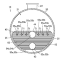
- FIG. 1 is a side view and a cross-sectional view showing an I-I cross section of the shell-and-plate heat exchanger of the first embodiment.
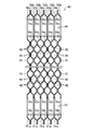
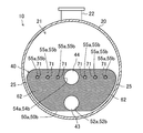
- FIG. 2 is a cross-sectional view of the shell-and-plate heat exchanger of the first embodiment, showing the II-II cross section of FIG.
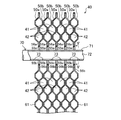
- FIG. 3 is a cross-sectional view of the plate laminate showing the III-III cross section of FIG.
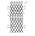
- FIG. 4 is a cross-sectional view of the plate laminate showing the IV-IV cross section of FIG.
- FIG. 5 is a cross-sectional view of a refrigerant introduction pipe showing a VV cross section of FIG.
- FIG. 6 is a cross-sectional view corresponding to FIG. 2, showing the flow of the refrigerant in the shell-and-plate heat exchanger.
- FIG. 7 is a cross-sectional view showing a cross section corresponding to FIG. 3 of the plate laminate of the second embodiment.
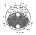
- FIG. 8 is a cross-sectional view of the shell-and-plate heat exchanger of the third embodiment, showing the IX-IX cross section of FIG.
- FIG. 9 is a cross-sectional view of the shell-and-plate heat exchanger of the third embodiment, showing a cross section of VIII-VIII of FIG.
- FIG. 10 is a plan view of the supply structure of the third embodiment.
- FIG. 11 is a cross-sectional view of the supply structure of the third embodiment showing the XI-XI cross section of FIG.
- FIG. 12 is a cross-sectional view showing a cross section corresponding to the II cross section of FIG.
- FIG. 13 is a cross-sectional view showing a cross section corresponding to the II cross section of FIG. 1 of the shell-and-plate heat exchanger of the second modification of the other embodiment.
- FIG. 14 is a cross-sectional view showing a cross section corresponding to FIG. 2 of the shell-and-plate heat exchanger of the third modification of the other embodiment.
- FIG. 15 is a cross-sectional view showing a cross section corresponding to FIG. 2 of the shell-and-plate heat exchanger of the third modification of the other embodiment.
- FIG. 16 is a cross-sectional view showing a cross section corresponding to FIG. 2 of the shell-and-plate heat exchanger of the fourth modification of the other embodiment.
- the shell-and-plate heat exchanger (10) (hereinafter referred to as “heat exchanger”) of the present embodiment is a flow-down liquid film type evaporator.
- the heat exchanger (10) of the present embodiment is provided in the refrigerant circuit of the refrigerating apparatus that performs the refrigerating cycle, and cools the heat medium with the refrigerant. Examples of the heat medium include water and brine.
- the heat exchanger (10) of the present embodiment includes a shell (20) and a plate laminate (40).
- the plate laminate (40) is housed in the interior space (21) of the shell (20).
- the heat exchanger (10) includes a plurality of (six in this embodiment) refrigerant introduction pipes (71) constituting the supply structure (70), and one refrigerant distributor (30).
- the shell (20) is formed in a cylindrical shape with both ends closed.
- the shell (20) is installed in a posture in which its longitudinal direction is lateral.
- a refrigerant outlet (22) for deriving the refrigerant from the internal space (21) of the shell (20) is provided.
- the refrigerant outlet (22) is provided near the right end of the shell (20) in FIG.
- the refrigerant outlet (22) is connected to the compressor of the refrigerator through a pipe.
- the shell (20) is provided with a heat medium inlet (23) and a heat medium outlet (24).
- Each of the heat medium inlet (23) and the heat medium outlet (24) is a tubular member.
- Each of the heat medium inlet (23) and the heat medium outlet (24) penetrates the left end of the shell (20) in FIG. 1 and is connected to the plate laminate (40).
- the heat medium inlet (23) is connected to the heat medium introduction path (43) of the plate laminate (40), and the heat medium is supplied to the plate laminate (40).
- the heat medium outlet (24) is connected to the heat medium lead-out path (44) of the plate laminate (40), and the heat medium is led out from the plate laminate (40).
- the plate laminate (40) is composed of a plurality of laminated heat transfer plates (50a, 50b).
- the plate laminate (40) is housed in the internal space (21) of the shell (20) in a posture in which the heat transfer plates (50a, 50b) are laminated in the lateral direction.
- the heat transfer plates (50a, 50b) constituting the plate laminate (40) are substantially semicircular plate-shaped members.
- the plate laminate (40) is arranged near the bottom of the internal space (21) of the shell (20) in a posture in which the arcuate edges of the heat transfer plates (50a, 50b) face downward.
- a protruding support portion for supporting the plate laminate (40) is provided on the inner surface of the shell (20).
- the plate laminate (40) In the state of being housed in the internal space (21) of the shell (20), the plate laminate (40) is separated from the inner surface of the shell (20), and the heat transfer plate (50a) constituting the plate laminate (40) is formed.
- a gap (25) is formed between the downward edge of (, 50b) and the inner surface of the shell (20).
- a first plate (50a) and a second plate (50b) having different shapes are provided as heat transfer plates.
- the plate laminate (40) includes a plurality of first plates (50a) and a plurality of second plates (50b).
- the first plate (50a) and the second plate (50b) are alternately laminated.
- the left side surface in FIG. 3 is the front surface
- the right side surface in FIG. 3 is the back surface.
- ⁇ Refrigerant flow path, heat medium flow path> As shown in FIG. 3, in the plate laminate (40), a plurality of refrigerant flow paths (41) and a plurality of heat medium flow paths (42) are formed with the heat transfer plates (50a, 50b) interposed therebetween. The refrigerant flow path (41) and the heat medium flow path (42) are separated from each other by heat transfer plates (50a, 50b).
- the refrigerant flow path (41) is a flow path sandwiched between the front surface of the first plate (50a) and the back surface of the second plate (50b).
- the refrigerant flow path (41) communicates with the internal space (21) of the shell (20).
- the heat medium flow path (42) is a flow path sandwiched between the back surface of the first plate (50a) and the front surface of the second plate (50b).
- the heat medium flow path (42) is cut off from the internal space (21) of the shell (20), while communicating with the heat medium inlet (23) and the heat medium outlet (24) attached to the shell (20).
- a large number of dimples (61) are formed on the first plate (50a) and the second plate (50b).
- the dimples (61) of the first plate (50a) bulge toward the surface side of the first plate (50a).
- the dimples (61) of the second plate (50b) bulge toward the back surface side of the second plate (50b).
- the first plate (50a) is formed with an inlet convex portion (51a) and an outlet convex portion (53a).
- Each of the inlet convex portion (51a) and the outlet convex portion (53a) is a circular portion that bulges toward the surface side of the first plate (50a).
- Each of the inlet convex portion (51a) and the outlet convex portion (53a) is formed at the central portion in the width direction of the first plate (50a).
- the inlet protrusion (51a) is formed in the lower part of the first plate (50a).
- the outlet protrusion (53a) is formed on top of the first plate (50a).
- a first entrance hole (52a) is formed in the central portion of the entrance convex portion (51a).
- a first outlet hole (54a) is formed at the center of the outlet convex portion (53a).
- Each of the first inlet hole (52a) and the first exit hole (54a) is a circular hole penetrating the first plate (50a) in the thickness direction.
- the second plate (50b) is formed with an inlet recess (51b) and an outlet recess (53b).
- Each of the inlet recess (51b) and the outlet recess (53b) is a circular portion that bulges toward the back surface side of the second plate (50b).
- Each of the inlet recess (51b) and the outlet recess (53b) is formed in the central portion in the width direction of the second plate (50b).
- the inlet recess (51b) is formed in the lower part of the second plate (50b).
- the outlet recess (53b) is formed on top of the second plate (50b).
- a second inlet hole (52b) is formed in the center of the inlet recess (51b).
- a second outlet hole (54b) is formed in the center of the outlet recess (53b).
- Each of the second inlet hole (52b) and the second exit hole (54b) is a circular hole penetrating the second plate (50b) in the thickness direction.
- the inlet recess (51b) is formed at a position corresponding to the inlet protrusion (51a) of the first plate (50a), and the outlet recess (53b) is formed in the first plate (50a). It is formed at a position corresponding to the outlet protrusion (53a).
- the second inlet hole (52b) is formed at a position corresponding to the first inlet hole (52a) of the first plate (50a), and the second outlet hole (54b) is formed. It is formed at a position corresponding to the first outlet hole (54a) of the first plate (50a).
- the diameters of the first inlet hole (52a) and the second inlet hole (52b) are substantially equal to each other.
- the diameters of the first outlet hole (54a) and the second outlet hole (54b) are substantially equal to each other.
- each first plate (50a) is welded to the peripheral edge of the second plate (50b) adjacent to the back surface side of the first plate (50a) over the entire circumference. Be joined.
- the first inlet hole (52a) of each first plate (50a) is the second inlet of the second plate (50b) adjacent to the surface side of the first plate (50a). The edges of the first inlet hole (52a) and the second inlet hole (52b) that overlap with the hole (52b) are joined by welding over the entire circumference.
- the first outlet hole (54a) of each first plate (50a) is the second outlet of the second plate (50b) adjacent to the surface side of the first plate (50a).
- the edges of the first outlet hole (54a) and the second outlet hole (54b) that overlap with the hole (54b) are joined by welding over the entire circumference.
- the inlet convex portion (51a) and the first inlet hole (52a) of each first plate (50a), and the inlet recess (51b) and the second inlet hole of each second plate (50b). (52b) and the heat medium introduction path (43) are formed. Further, in the plate laminated body (40), the outlet convex portion (53a) and the first outlet hole (54a) of each first plate (50a), and the outlet concave portion (53b) and the second outlet concave portion (53b) of each second plate (50b). The outlet hole (54b) and the heat medium outlet path (44) are formed.
- Each of the heat medium introduction path (43) and the heat medium lead-out path (44) is a passage extending in the stacking direction of the heat transfer plates (50a, 50b) in the plate laminate (40).
- the heat medium introduction path (43) is a passage cut off from the internal space (21) of the shell (20), and all the heat medium flow paths (42) are communicated with the heat medium inlet (23).
- the heat medium lead-out path (44) is a passage cut off from the internal space (21) of the shell (20), and all the heat medium flow paths (42) are communicated with the heat medium outlet (24).
- first circular holes (55a) are formed in the first plate (50a).
- the first circular hole (55a) is a circular hole that penetrates the first plate (50a) in the thickness direction.
- the first plate (50a) is formed with the same number of first flat portions (56a) as the first circular holes (55a).
- Each first flat portion (56a) is a flat portion that surrounds one corresponding first circular hole (55a).
- the plurality of first circular holes (55a) are formed in the width direction (horizontal direction in FIG. 2) of the first plate (50a) along the upper edge of the first plate (50a). Arranged in a row.
- the plurality of first circular holes (55a) are arranged at predetermined intervals from each other.
- the same number of first circular holes (55a) are provided in each of the left side region and the right side region of the first outlet hole (54a) in FIG. 2 (three in this embodiment). It is formed.
- the distance from the top of each first circular hole (55a) to the top edge of the first plate (50a) is greater than the distance from the top of the first exit hole (54a) to the top edge of the first plate (50a). Is also long.
- a plurality of (six in this embodiment) second circular holes (55b) are formed in the second plate (50b).
- the second circular hole (55b) is a circular hole that penetrates the second plate (50b) in the thickness direction.
- the second plate (50b) is formed with the same number of second flat portions (56b) as the second circular holes (55b).
- Each second flat portion (56b) is a flat portion that surrounds one corresponding second circular hole (55b).
- the plurality of second circular holes (55b) are formed in the width direction (horizontal direction in FIG. 2) of the second plate (50b) along the upper edge of the second plate (50b). Arranged in a row.
- the plurality of second circular holes (55b) are arranged at predetermined intervals from each other.
- the same number of second circular holes (55b) are provided in each of the left side region and the right side region of the second exit hole (54b) in FIG. 2 (three in this embodiment). It is formed.
- the distance from the top of each second circular hole (55b) to the top edge of the second plate (50b) is greater than the distance from the top of the second exit hole (54b) to the top edge of the second plate (50b). Is also long.
- the second circular hole (55b) is formed at a position corresponding to the first circular hole (55a) of the first plate (50a).
- the diameters of the first circular hole (55a) and the second circular hole (55b) are substantially equal to each other.
- the first circular hole (55a) of each first plate (50a) is the second circular hole (50b) of the second plate (50b) adjacent to the back surface side of the first plate (50a).
- the edges of the first circular hole (55a) and the second circular hole (55b) that overlap with 55b) are joined by welding over the entire circumference.
- the six refrigerant introduction pipes (71) form a supply structure (70) for supplying the refrigerant to the refrigerant flow path (41) of the plate laminate (40).
- the refrigerant introduction pipe (71) is a circular tubular member.
- the internal space of the refrigerant introduction pipe (71) is the refrigerant introduction path (72).
- the refrigerant introduction pipe (71) is provided so as to penetrate the plate laminated body (40) in the laminating direction of the heat transfer plates (50a, 50b).
- the tip of the refrigerant introduction pipe (71) is closed.
- the base end of the refrigerant introduction pipe (71) penetrates the left end portion of the shell (20) in FIG. 1 and is exposed to the outside of the shell (20).
- the refrigerant introduction pipe (71) has the first circular hole (55a) of the overlapping first plate (50a) and the second circular hole (55b) of the second plate (50b). It is inserted into. Further, each refrigerant introduction pipe (71) penetrates the corresponding first circular hole (55a) and second circular hole (55b).
- the six refrigerant introduction pipes (71) are installed in a posture in which their axial directions are substantially horizontal and substantially parallel to each other. Further, the six refrigerant introduction pipes (71) are arranged in a row at predetermined intervals in the width direction of the heat transfer plates (50a, 50b).
- a plurality of supply holes (73) are provided in each of the portions of the plate laminate (40) that cross the refrigerant flow path (41) (three in the present embodiment). Formed (by each).
- the supply hole (73) penetrates the refrigerant introduction pipe (71) in the radial direction and opens to the inner and outer surfaces of the refrigerant introduction pipe (71).
- the supply hole (73) communicates the refrigerant introduction path (72) inside the refrigerant introduction pipe (71) with the refrigerant flow path (41) outside the refrigerant introduction pipe (71).
- three supply holes (73) are formed downward in each of the portions of the refrigerant introduction pipe (71) that cross the refrigerant flow path (41).
- a supply hole (73) facing directly below, a supply hole (73) facing diagonally downward to the right, and an obliquely lower left are provided at each portion crossing the refrigerant flow path (41).
- a supply hole (73) facing the surface is formed.
- the refrigerant distributor (30) is a member for distributing the refrigerant supplied to the heat exchanger (10) to all the refrigerant introduction pipes (71).
- the refrigerant distributor (30) includes a distributor main body (31) and a refrigerant inlet (32), and is arranged outside the shell (20).
- the distributor body (31) is a hollow member and is connected to the base end of each refrigerant introduction pipe (71) exposed to the outside of the shell (20).
- the refrigerant inlet (32) is a short circular tubular member connected to the distributor body (31).
- the distributor main body (31) distributes the refrigerant flowing in from the refrigerant inlet (32) to all the refrigerant introduction pipes (71).
- a gas-liquid two-phase low-pressure refrigerant that has passed through the expansion mechanism of the refrigerant circuit is supplied to the heat exchanger (10).
- the refrigerant supplied to the heat exchanger (10) flows into the distributor main body (31) from the refrigerant inlet (32) of the refrigerant distributor (30), and a plurality of (six in this embodiment) refrigerant introduction pipes. It will be distributed to (71).
- each refrigerant introduction pipe (71) The refrigerant that has flowed into the refrigerant introduction path (72) of each refrigerant introduction pipe (71) is supplied from each supply hole (73) toward the refrigerant flow path (41) of the corresponding plate laminate (40). At that time, the refrigerant is sprayed toward the front surface of the first plate (50a) facing the refrigerant flow path (41) and the back surface of the second plate (50b). Further, as shown in FIG. 6, the refrigerant is fan-shaped downward from the three supply holes (73) corresponding to the respective refrigerant flow paths (41). In FIG. 6, the dimples (61) of the heat transfer plates (50a, 50b) are not shown.
- the refrigerant supplied to the refrigerant flow path (41) flows down along the front surface of the first plate (50a) or the back surface of the second plate (50b), and in the process, from the heat medium flowing through the heat medium flow path (42). It absorbs heat and evaporates.
- a large number of dimples (61) are formed on the heat transfer plates (50a, 50b) of the present embodiment.
- the liquid refrigerant flowing downward along the heat transfer plates (50a, 50b) hits the dimples (61) and diffuses in the left-right direction.
- the area of the front surface or the back surface of the heat transfer plate (50a, 50b) that comes into contact with the liquid refrigerant is expanded, and the time that the liquid refrigerant stays on the front surface or the back surface of the heat transfer plate (50a, 50b) becomes long.
- the liquid refrigerant that did not evaporate in the process of flowing down along the heat transfer plates (50a, 50b) collects. Therefore, the lower portion of the plate laminate (40) is immersed in the liquid refrigerant. In the portion of the plate laminate (40) that is immersed in the liquid refrigerant, the liquid refrigerant that fills the refrigerant flow path (41) is heated by the heat medium of the heat medium flow path (42) and evaporates.
- the gas refrigerant generated in the refrigerant flow path (41) flows upward in the refrigerant flow path (41) and is arranged in the width direction of the heat transfer plates (50a, 50b). It passes between the introduction pipes (71) and flows into the space above the plate laminate (40). Further, a part of the gas refrigerant generated in the refrigerant flow path (41) flows laterally and flows into the gap (25) between the plate laminate (40) and the shell (20), and this gap (25) It flows through the space above the plate laminate (40).
- the refrigerant flowing into the space above the plate laminate (40) contains fine droplet-like liquid refrigerant.
- the space above the plate laminate (40) is a relatively large space, the flow velocity of the refrigerant flowing through this space is relatively low. Therefore, most of the droplet-shaped liquid refrigerant contained in the refrigerant falls downward due to gravity.
- the refrigerant that has flowed into the space above the plate laminate (40) flows out of the shell (20) through the refrigerant outlet (22). The refrigerant flowing out of the shell (20) is sucked into the compressor of the refrigerator.
- the heat medium supplied to the heat exchanger (10) flows into the heat medium introduction path (43) of the plate laminate (40) through the heat medium inlet (23) and into each heat medium flow path (42). Will be distributed.
- the heat medium flowing into each heat medium flow path (42) generally flows upward while spreading in the width direction of the heat transfer plates (50a, 50b).
- the heat medium dissipates heat to the refrigerant flowing through the refrigerant flow path (41). As a result, the temperature of the heat medium drops.
- each heat medium flow path (42) flows into the heat medium lead-out path (44) and merges with the heat medium that has passed through the other heat medium flow paths (42). After that, the heat medium in the heat medium lead-out path (44) flows out to the outside of the heat exchanger (10) through the heat medium outlet (24) and is used for air conditioning and the like.
- the shell-and-plate heat exchanger (10) of the present embodiment includes a supply structure (70) for supplying the refrigerant to the refrigerant flow path (41).
- the refrigerant supplied to the refrigerant flow path (41) exchanges heat with the heat medium flowing through the heat medium flow path (42) and evaporates in the process of flowing downward along the heat transfer plates (50a, 50b).
- the shell-and-plate heat exchanger (10) of the present embodiment functions as a flowing liquid film type evaporator.
- a supply structure (70) for supplying a refrigerant to the plate laminate (40) is provided in the shell (20). It is assumed that it is placed above 40).
- the supply structure (70) is arranged above the plate laminate (40)
- the space above the plate laminate (40) in the shell (20) is narrowed, and the refrigerant in the space above the plate laminate (40) is narrowed. There is a risk that the flow velocity will increase.
- the gas refrigerant flowing upward from the plate laminate (40) includes a droplet-shaped liquid refrigerant. Then, when the flow velocity of the refrigerant in the space above the plate laminate (40) increases, the number of droplets that flow together with the gas refrigerant without falling due to gravity increases. As a result, the amount of liquid refrigerant flowing out of the shell (20) along with the gas refrigerant increases, and the performance of the heat exchanger (10) deteriorates.
- the supply structure (70) is arranged inside the outer peripheral edge of the heat transfer plates (50a, 50b) in the plate laminate (40). Therefore, the space above the plate laminate (40) in the shell (20) is secured, and the flow velocity of the refrigerant in the space above the plate laminate (40) is suppressed to be low. As a result, the amount of the liquid refrigerant flowing out from the shell (20) together with the gas refrigerant is suppressed to a low level, and the performance of the heat exchanger (10) is improved.
- the supply structure (70) of the present embodiment includes a refrigerant introduction path (72) and a supply hole (73).
- the refrigerant introduction path (72) is formed so as to penetrate the heat transfer plates (50a, 50b) of the plate laminate (40).
- the supply hole (73) communicates the refrigerant introduction path (72) with the refrigerant flow path (41) to supply the refrigerant to the refrigerant flow path (41).
- the refrigerant flowing through the refrigerant introduction path (72) is supplied to the refrigerant flow path (41) of the plate laminate (40) through the supply hole (73).
- Embodiment 1 (4)-
- a plurality of supply holes (73) are provided corresponding to each of the plurality of refrigerant flow paths (41) formed in the plate laminate (40).
- the refrigerant is supplied from the plurality of supply holes (73) to each of the plurality of refrigerant flow paths (41) formed in the plate laminate (40). Therefore, the liquid refrigerant can be supplied to a wide range of the front surface or the back surface of the heat transfer plate (50a, 50b), and the heat exchange between the refrigerant and the heat medium can be promoted.
- the refrigerant introduction path (72) is formed by the refrigerant introduction pipe (71).
- the refrigerant introduction pipe (71) penetrates a plurality of heat transfer plates (50a, 50b) of the plate laminate (40).
- the supply hole (73) penetrates the refrigerant introduction pipe (71) and opens to the inner and outer surfaces of the refrigerant introduction pipe (71).
- a supply hole (73) is formed in the refrigerant introduction pipe (71) forming the refrigerant introduction path (72).
- the supply hole (73) penetrates the refrigerant introduction pipe (71) and communicates the refrigerant introduction path (72) with the refrigerant flow path (41).
- the heat exchanger (10) of the present embodiment includes a plurality of supply structures (70).
- a plurality of feed structures (70) are provided along the upward edges of the heat transfer plates (50a, 50b) of the plate laminate (40) at predetermined intervals from each other.
- the heat exchanger (10) of the present embodiment is provided with a plurality of supply structures (70).
- the plurality of supply structures (70) are arranged at predetermined intervals from each other.
- the refrigerant evaporated by heat exchange with the heat medium in the plate laminate (40) flows between the plurality of supply structures (70) to the space above the plate laminate (40).
- a heat medium introduction path (43) and a heat medium lead-out path (44) are formed in the plate laminate (40) of the present embodiment.
- Each of the heat medium introduction path (43) and the heat medium lead-out path (44) is formed so as to penetrate the heat transfer plate (50a, 50b) and communicates with the heat medium flow path (42).
- Each of the heat medium introduction path (43) and the heat medium lead-out path (44) is formed in the central portion in the width direction of the heat transfer plates (50a, 50b).
- the same number of supply structures (70) are provided in the right side region and the left side region of the heat transfer medium introduction path (43) and the heat medium lead-out path (44) in the width direction of the heat transfer plates (50a, 50b). ..
- a heat medium introduction path (43) and a heat medium lead-out path (44) are formed in the central portion in the width direction of the heat transfer plates (50a, 50b). Further, in this plate laminate (40), in the right side region and the left side region of the heat transfer medium introduction path (43) and the heat medium lead-out path (44) in the width direction of the heat transfer plates (50a, 50b), respectively.
- the same number of supply structures (70) are provided. Therefore, the liquid refrigerant can be supplied from the supply structure (70) to a wide area on the surface of the heat transfer plates (50a, 50b).
- the heat exchanger (10) of the present embodiment includes a refrigerant distributor (30) that distributes the refrigerant to a plurality of supply structures (70).
- the refrigerant supplied to the heat exchanger (10) of the present embodiment is distributed to a plurality of supply structures (70) by the refrigerant distributor (30), and the refrigerant of the plate laminate (40) is distributed from each supply structure (70). It is supplied to the flow path (41).
- the heat exchanger (10) of the present embodiment is configured so that the liquid refrigerant collects at the bottom of the internal space (21) of the shell (20).
- the plate laminate (40) is provided at a position where the lower portion of the plate laminate (40) is immersed in the liquid refrigerant collected at the bottom of the internal space (21).
- the lower part of the plate laminate (40) is immersed in the liquid refrigerant collected at the bottom of the internal space (21).
- the refrigerant supplied from the supply structure (70) to the refrigerant flow path (41) of the plate laminate (40) and the accumulated refrigerant at the bottom of the internal space (21) exchanges heat with the heat medium in the heat medium flow path (42) and evaporates.
- the plate laminate (40) of the present embodiment is provided at a position where a gap (25) is formed between the downward edge of the heat transfer plate (50a, 50b) and the inner surface of the shell (20).
- a part of the refrigerant evaporated in the plate laminate (40) flows upward through the refrigerant flow path (41), while the rest flows upward through the refrigerant flow path (41). Flows out into the gap (25) between the plate laminate (40) and the shell (20) and flows upward through the gap (25). Therefore, the discharge of the gas refrigerant from the refrigerant flow path (41) of the plate laminate (40) can be promoted.
- the heat exchanger (10) of the present embodiment is the heat exchanger (10) of the first embodiment in which the supply structure (70) is changed.
- the heat exchanger (10) of the present embodiment will be described as different from the heat exchanger (10) of the first embodiment.
- the refrigerant introduction pipe (71) is omitted, and the refrigerant introduction path (72) is provided by the heat transfer plates (50a, 50b) of the plate laminate (40). Is formed. Further, in the supply structure (70) of the present embodiment, the supply holes (73) are formed in the heat transfer plates (50a, 50b) of the plate laminate (40).
- a plurality of (six in this embodiment) circular protrusions (57a) are formed on the first plate (50a) of the present embodiment.
- the circular convex portion (57a) is a circular portion that bulges toward the surface side of the first plate (50a).
- the first flat portion (56a) is formed so as to surround the circular convex portion (57a).
- the first circular hole (55a) is formed in the circular convex portion (57a).
- the position of the first circular hole (55a) in the first plate (50a) of the present embodiment is substantially the same as the position of the first circular hole (55a) in the first plate (50a) of the first embodiment.
- a plurality of (six in this embodiment) circular recesses (57b) are formed in the second plate (50b) of the present embodiment.
- the circular recess (57b) is a circular portion that bulges toward the back surface side of the second plate (50b).
- the second flat portion (56b) is formed so as to surround the circular recess (57b).
- a second circular hole (55b) is formed in the circular recess (57b).
- the position of the second circular hole (55b) in the second plate (50b) of the present embodiment is substantially the same as the position of the second circular hole (55b) in the second plate (50b) of the first embodiment.
- the diameters of the first circular hole (55a) and the second circular hole (55b) are substantially equal to each other.
- the first circular hole (55a) of each first plate (50a) is the first of the second plate (50b) adjacent to the surface side of the first plate (50a). The edges of the first circular hole (55a) and the second circular hole (55b) that overlap with the two circular holes (55b) are joined by welding over the entire circumference.
- the first flat portion (56a) of each first plate (50a) is the second plate (50b) of the second plate (50b) located on the back surface side of the first plate (50a). 2 Contact the flat part (56b). Then, the first flat portion (56a) and the second flat portion (56b) that are in contact with each other are joined by brazing. The first flat portion (56a) and the second flat portion (56b) that are in contact with each other may be joined by welding.
- a refrigerant introduction path (72) is formed by the second inlet hole (52b).
- the refrigerant introduction path (72) is a passage extending in the stacking direction of the heat transfer plates (50a, 50b) in the plate laminated body (40).
- the refrigerant introduction path (72) is a passage that is shielded from both the heat medium flow path (42) of the plate laminate (40) and the internal space (21) of the shell (20).
- a plurality of (six in this embodiment) refrigerant introduction paths (72) formed in the plate laminate (40) are connected to the distributor main body (31) of the refrigerant distributor (30) via pipes or the like. NS.
- the supply hole (73) of the present embodiment is formed in the heat transfer plate (50a, 50b).
- a supply hole (73) is formed in the lower part of the slope portion of the circular convex portion (57a).
- the supply hole (73) penetrates the first plate (50a) in the thickness direction.
- the supply hole (73) opens on the front surface and the back surface of the first plate (50a), and communicates the refrigerant flow path (41) facing the front surface of the first plate (50a) with the refrigerant introduction path (72).
- a supply hole (73) is formed in the lower part of the slope portion of the circular recess (57b).
- the supply hole (73) penetrates the second plate (50b) in the thickness direction.
- the supply hole (73) opens on the front surface and the back surface of the second plate (50b), and communicates the refrigerant flow path (41) facing the back surface of the second plate (50b) with the refrigerant introduction path (72).
- the refrigerant supplied to the heat exchanger (10) flows into the distributor main body (31) from the refrigerant inlet (32) of the refrigerant distributor (30), and a plurality of (six in this embodiment) refrigerant introduction paths. It will be distributed to (72).
- the refrigerant that has flowed into each refrigerant introduction path (72) is supplied from each supply hole (73) toward the refrigerant flow path (41) of the corresponding plate laminate (40). At that time, the refrigerant is sprayed toward the front surface of the first plate (50a) facing the refrigerant flow path (41) and the back surface of the second plate (50b).
- the refrigerant introduction path (72) is formed by joining a plurality of heat transfer plates (50a, 50b) of the plate laminate (40). Further, in this supply structure (70), the supply hole (73) penetrates the heat transfer plate (50a, 50b) and opens on the front surface and the back surface of the heat transfer plate (50a, 50b).
- the refrigerant introduction path (72) is formed by the plurality of joined heat transfer plates (50a, 50b).
- the supply hole (73) penetrates the heat transfer plates (50a, 50b) and communicates the refrigerant introduction path (72) with the refrigerant flow path (41). Therefore, according to the present embodiment, the heat exchanger (10) can be provided with the supply structure (70) without adding a new member to the heat exchanger (10).
- the heat exchanger (10) of the present embodiment is the heat exchanger (10) of the first embodiment in which the structures of the plate laminate (40) and the supply structure (70) are changed.
- the heat exchanger (10) of the present embodiment will be described as different from the heat exchanger (10) of the first embodiment.
- the supply structure (70) is arranged above the plate laminate (40) in the internal space (21) of the shell (20). Will be done.
- the supply structure (70) of the present embodiment is provided at a position close to the upper edge of the heat transfer plates (50a, 50b) constituting the plate laminate (40).
- the heat transfer plates (50a, 50b) constituting the plate laminate (40) are different from those of the first embodiment.
- the first circular hole (55a) and the first flat portion (56a) are omitted.
- the second circular hole (55b) and the second flat portion (56b) are omitted.
- the supply structure (70) of the present embodiment includes one distribution tray (75), a plurality of spray trays (76), and one inlet pipe (77).
- the distribution tray (75) is an elongated rectangular parallelepiped member having an open upper surface.
- the length of the distribution tray (75) is approximately equal to the overall length of the plate laminate (40) (the length of the heat transfer plates (50a, 50b) in the stacking direction) (see FIG. 8).
- a plurality of distribution holes (75a) are formed in the bottom plate of the distribution tray (75).
- the number of distribution holes (75a) matches the number of spray trays (76).
- the distribution hole (75a) is a circular hole that penetrates the bottom plate of the distribution tray (75).
- the plurality of distribution holes (75a) are arranged in a row along the longitudinal direction of the distribution tray (75) at regular intervals from each other.
- the upper surface of the distribution tray (75) may be closed.
- the spray tray (76) is an elongated rectangular parallelepiped member with an open upper surface.
- the length of the spray tray (76) is approximately equal to the overall width of the plate laminate (40) (width of the heat transfer plates (50a, 50b)) (see FIG. 9).
- a plurality of spray holes (76a) are formed in the bottom plate of the spray tray (76).
- the spray hole (76a) is a circular hole that penetrates the bottom plate of the spray tray (76).
- the plurality of spray holes (76a) are arranged in a row along the longitudinal direction of the spray tray (76) at regular intervals from each other.
- the upper surface of the spray tray (76) may be closed. However, even in that case, the portion of the upper surface of the spray tray (76) located directly below the distribution tray (75) must be open.
- each spray tray (76) is placed below the distribution tray (75).
- the long side of each spray tray (76) is substantially orthogonal to the long side of the distribution tray (75).
- the plurality of spray trays (76) are arranged at regular intervals in the longitudinal direction of the distribution tray (75) in a posture in which their long sides are parallel to each other.
- the longitudinal center of each spray tray (76) is located below one corresponding distribution hole (75a).
- the inlet pipe (77) is a pipe for introducing the refrigerant supplied to the heat exchanger (10) into the distribution tray (75).
- the inlet pipe (77) is connected to the side wall on one short side of the distribution tray (75), penetrates the side wall, and opens inside the distribution tray (75).
- the supply structure (70) of the present embodiment is arranged above the plate laminate (40).
- the supply structure (70) has an internal space (21) of the shell (20) in a posture in which the longitudinal direction of the distribution tray (75) is substantially parallel to the longitudinal direction of the shell (20). Will be installed in.
- the inlet pipe (77) of the supply structure (70) penetrates the left end of the shell (20) in FIG. 8 and extends to the outside of the shell (20).
- the distribution tray (75) is arranged in the center of the plate laminate (40) in the width direction.
- Each spray tray (76) is arranged along the upper edge of the heat transfer plates (50a, 50b) constituting the plate laminate (40).
- the bottom surface of each spray tray (76) faces the upper edge of the heat transfer plates (50a, 50b).
- the bottom surface of each spray tray (76) is substantially parallel to the upper edge of the heat transfer plates (50a, 50b).
- the refrigerant supplied to the heat exchanger (10) flows into the distribution tray (75) through the inlet pipe (77) of the supply structure (70).
- the refrigerant flowing into the distribution tray (75) is distributed to each spray tray (76). Specifically, the refrigerant that has flowed into the distribution tray (75) flows downward through the distribution holes (75a) and flows into the spray tray (76) corresponding to each distribution hole (75a).
- each spray tray (76) the refrigerant flowing in from the distribution tray (75) flows downward through each spray hole (76a).
- Each spray tray (76) supplies refrigerant to substantially the entire width direction of the plate laminate (40).
- the refrigerant that has passed through the spray holes of the spray tray (76) flows into the refrigerant flow path (41) of the plate laminate (40) and exchanges heat with the heat medium in the process of flowing down through the heat transfer plates (50a, 50b). And evaporate.
- the heat exchangers (10) of embodiments 1 to 3 may include an eliminator (15).
- the eliminator (15) is a member for capturing the droplet-shaped liquid refrigerant flowing together with the gas refrigerant.
- the eliminator (15) is formed in the shape of a plate formed by, for example, laminating metal meshes, and the refrigerant can pass through in the thickness direction thereof.
- the eliminator (15) is housed in the internal space (21) of the shell (20).
- the eliminator (15) is installed so as to traverse the upper portion of the plate laminate (40) in the interior space (21) of the shell (20).
- the gas refrigerant heading from the plate laminate (40) to the refrigerant outlet (22) passes through the eliminator (15).
- the droplet-shaped liquid refrigerant contained in the gas refrigerant adheres to the eliminator (15) and is separated from the gas refrigerant.
- the gas refrigerant that has passed through the eliminator (15) flows out of the shell (20) through the refrigerant outlet (22).
- the liquid refrigerant captured by the eliminator (15) becomes relatively large droplets and falls downward.
- the heat exchangers (10) of the first to third embodiments may include a gas-liquid separator (16).
- the gas-liquid separator (16) is a container-shaped member that separates the gas-liquid two-phase state refrigerant introduced inside into a liquid refrigerant and a gas refrigerant.
- a liquid outlet (17) is provided at the bottom of the gas-liquid separator (16).
- a gas outlet (18) is provided above the gas-liquid separator (16).
- the gas-liquid separator (16) is housed in the internal space (21) of the shell (20) and is installed above the plate laminate (40).
- the refrigerant inlet (32) is connected to the gas-liquid separator (16).
- the refrigerant distributor (30) is housed in the internal space (21) of the shell (20).
- the liquid outlet (17) of the gas-liquid separator (16) is connected to the distributor main body (31) of the refrigerant distributor (30) via a pipe.
- the gas outlet (18) of the gas-liquid separator (16) opens into the interior space (21) of the shell (20).
- the gas-liquid two-phase state refrigerant supplied to the heat exchanger (10) flows into the gas-liquid separator (16) through the refrigerant inlet (32) and is separated into a liquid refrigerant and a gas refrigerant.
- the liquid refrigerant of the gas-liquid separator (16) flows into the refrigerant distributor (30) through the liquid outlet (17) and is supplied to the refrigerant flow path (41) of the plate laminate (40).
- the gas refrigerant of the gas-liquid separator (16) flows into the internal space (21) of the shell (20) through the gas outlet (18), and together with the gas refrigerant evaporated in the plate laminate (40), the refrigerant outlet ( It flows out of the shell (20) through 22).
- elongated ridge-shaped irregularities are repeatedly formed on the heat transfer plates (50a, 50b) constituting the plate laminate (40) instead of the dimples (61).
- the uneven pattern (62) may be formed.
- the uneven pattern (62) formed on the heat transfer plate (50a, 50b) has a shape in which the ridgeline of the unevenness extends in the width direction of the heat transfer plate (50a, 50b). good.
- the uneven pattern (62) formed on the heat transfer plates (50a, 50b) may have a meandering shape so as to bend left and right. Similar to the dimples (61), these uneven patterns (62) diffuse the liquid refrigerant flowing downward along the heat transfer plates (50a, 50b) in the left-right direction.
- the shape of the heat transfer plates (50a, 50b) constituting the plate laminate (40) is not limited to a semicircular shape.
- the heat transfer plates (50a, 50b) may be formed in an elliptical shape.
- the heat transfer plates (50a, 50b) may be formed in a circular shape.
- the plurality of heat transfer plates (50a, 50b) constituting the plate laminate (40) may be joined to each other by brazing.
- the present disclosure is useful for shell-and-plate heat exchangers.
Landscapes
- Engineering & Computer Science (AREA)
- Physics & Mathematics (AREA)
- Thermal Sciences (AREA)
- Mechanical Engineering (AREA)
- General Engineering & Computer Science (AREA)
- Heat-Exchange Devices With Radiators And Conduit Assemblies (AREA)
Abstract
シェルアンドプレート式熱交換器(10)では、シェル(20)にプレート積層体(40)が収容される。プレート積層体(40)は、複数の伝熱プレート(50a,50b)を有する。プレート積層体(40)には、冷媒流路(41)と熱媒体流路(42)とが複数ずつ形成される。熱交換器(10)は、プレート積層体(40)の冷媒流路(41)へ冷媒を供給する供給構造(70)を備える。供給構造(70)は、冷媒流路(41)に対して、冷媒を下方へ流れ落ちるように供給する。
Description
本開示は、シェルアンドプレート式熱交換器に関するものである。
特許文献1に開示されているようなシェルアンドプレート式熱交換器が知られている。このシェルアンドプレート式熱交換器は、複数の伝熱プレートによって構成されたプレート積層体と、プレート積層体を収容するシェルとを備える。
特許文献1の熱交換器は、満液式の蒸発器である。この熱交換器では、シェル内に貯留された液冷媒にプレート積層体が浸かる。シェル内の液冷媒は、プレート積層体を流れる熱媒体と熱交換して蒸発し、シェルの上部に設けられた冷媒出口を通ってシェルの外部へ流出する。
シェルアンドプレート式熱交換器によって構成された流下液膜式の蒸発器は、存在しない。そのため、従来は、シェルアンドプレート式熱交換器の用途が限られていた。
本開示の目的は、シェルアンドプレート式熱交換器の用途を拡大することにある。
本開示の第1の態様は、内部空間(21)を形成するシェル(20)と、重ね合わされて互いに接合された複数の伝熱プレート(50a,50b)を有して上記シェル(20)の上記内部空間(21)に収容されるプレート積層体(40)とを備え、上記シェル(20)の上記内部空間(21)へ流入した冷媒を蒸発させるシェルアンドプレート式熱交換器(10)を対象とする。そして、上記プレート積層体(40)には、上記シェル(20)の上記内部空間(21)に連通して冷媒が流れる冷媒流路(41)と、上記シェル(20)の上記内部空間(21)から遮断されて熱媒体が流れる熱媒体流路(42)とが、上記伝熱プレート(50a,50b)を挟んで隣り合うように複数ずつ形成され、上記冷媒流路(41)に対して冷媒を下方へ流れ落ちるように供給する供給構造(70)を備えることを特徴とする。
第1の態様では、プレート積層体(40)の冷媒流路(41)に、供給構造(70)から冷媒が供給される。供給構造(70)がプレート積層体(40)へ供給した冷媒は、冷媒流路(41)を下方へ流れ落ちる過程で、熱媒体流路(42)を流れる熱媒体と熱交換して蒸発する。この態様のシェルアンドプレート式熱交換器(10)は、流下液膜式の蒸発器を構成する。
本開示の第2の態様は、上記第1の態様において、上記供給構造(70)は、上記プレート積層体(40)における上記伝熱プレート(50a,50b)の外周縁よりも内側に配置されることを特徴とする。
第2の態様では、供給構造(70)が、プレート積層体(40)における伝熱プレート(50a,50b)の外周縁よりも内側に配置される。このため、シェル(20)内におけるプレート積層体(40)の上方の空間が確保され、プレート積層体(40)の上方の空間における冷媒の流速が低く抑えられる。その結果、ガス冷媒と共にシェル(20)から流出する液冷媒の量が低く抑えられ、シェルアンドプレート式熱交換器(10)の性能が向上する。
本開示の第3の態様は、上記第2の態様において、上記供給構造(70)は、上記プレート積層体(40)の上記伝熱プレート(50a,50b)を貫通するように形成された冷媒導入路(72)と、上記冷媒導入路(72)を上記冷媒流路(41)に連通させて冷媒を上記冷媒流路(41)へ供給する供給孔(73)とを備えることを特徴とする。
第3の態様では、供給構造(70)が冷媒導入路(72)と供給孔(73)とを備える。供給構造(70)では、冷媒導入路(72)を流れる冷媒が、供給孔(73)を通ってプレート積層体(40)の冷媒流路(41)へ供給される。
本開示の第4の態様は、上記第3の態様において、上記供給構造(70)の上記供給孔(73)は、上記プレート積層体(40)に形成された複数の上記冷媒流路(41)のそれぞれに対応して複数ずつ設けられることを特徴とする。
第4の態様では、プレート積層体(40)に形成された複数の冷媒流路(41)のそれぞれに対して、複数の供給孔(73)から冷媒が供給される。そのため、伝熱プレート(50a,50b)の表面または裏面の広い範囲に液冷媒を供給でき、冷媒と熱媒体の熱交換を促進できる。
本開示の第5の態様は、上記第3又は第4の態様において、上記冷媒導入路(72)は、上記プレート積層体(40)の複数の上記伝熱プレート(50a,50b)を貫通する冷媒導入管(71)によって形成され、上記供給孔(73)は、上記冷媒導入管(71)を貫通して該冷媒導入管(71)の内面と外面に開口することを特徴とする。
第5の態様では、冷媒導入路(72)を形成する冷媒導入管(71)に、供給孔(73)が形成される。供給孔(73)は、冷媒導入管(71)を貫通して冷媒導入路(72)を冷媒流路(41)に連通させる。
本開示の第6の態様は、上記第3又は第4の態様において、上記冷媒導入路(72)は、上記プレート積層体(40)の複数の上記伝熱プレート(50a,50b)を接合することによって形成され、上記供給孔(73)は、上記伝熱プレート(50a,50b)を貫通して該伝熱プレート(50a,50b)の表面と裏面に開口することを特徴とする。
第6の態様では、接合された複数の伝熱プレート(50a,50b)によって冷媒導入路(72)が形成される。供給孔(73)は、伝熱プレート(50a,50b)を貫通して冷媒導入路(72)を冷媒流路(41)に連通させる。
本開示の第7の態様は、上記第2~第6のいずれか一つの態様において、複数の上記供給構造(70)が、上記プレート積層体(40)の上記伝熱プレート(50a,50b)の上向きの縁部に沿って、互いに所定の間隔をおいて設けられることを特徴とする。
第7の態様では、シェルアンドプレート式熱交換器(10)に複数の供給構造(70)が設けられる。複数の供給構造(70)は、互いに所定の間隔をおいて配置される。プレート積層体(40)において熱媒体と熱交換して蒸発した冷媒は、複数の供給構造(70)の間を通ってプレート積層体(40)の上方の空間へ流れる。
本開示の第8の態様は、上記第7の態様において、上記プレート積層体(40)には、上記伝熱プレート(50a,50b)を貫通するように形成されて上記熱媒体流路(42)に連通する熱媒体導入路(43)及び熱媒体導出路(44)が、上記伝熱プレート(50a,50b)の幅方向の中央部に形成され、上記供給構造(70)は、上記伝熱プレート(50a,50b)の幅方向における上記熱媒体導入路(43)及び上記熱媒体導出路(44)の右側の領域と左側の領域のそれぞれに同数ずつ設けられることを特徴とする。
第8の態様のプレート積層体(40)では、伝熱プレート(50a,50b)の幅方向の中央部に熱媒体導入路(43)及び熱媒体導出路(44)が形成される。また、このプレート積層体(40)では、伝熱プレート(50a,50b)の幅方向における熱媒体導入路(43)及び熱媒体導出路(44)の右側の領域と左側の領域のそれぞれに、同数ずつの供給構造(70)が設けられる。このため、伝熱プレート(50a,50b)の表面の広い領域に対して、供給構造(70)から液冷媒を供給できる。
本開示の第9の態様は、上記第7又は第8の態様において、冷媒を複数の上記供給構造(70)へ分配する冷媒分配器(30)を備えることを特徴とする。
第9の態様において、シェルアンドプレート式熱交換器(10)へ供給される冷媒は、冷媒分配器(30)によって複数の供給構造(70)へ分配され、各供給構造(70)からプレート積層体(40)の冷媒流路(41)へ供給される。
本開示の第10の態様は、上記第1~第9のいずれか一つの態様において、上記シェル(20)の上記内部空間(21)の底部に液冷媒が溜まるように構成され、上記プレート積層体(40)は、該プレート積層体(40)の下部が上記内部空間(21)の底部に溜まった液冷媒に浸かるような位置に設けられることを特徴とする。
第10の態様では、プレート積層体(40)の下部が、内部空間(21)の底部に溜まった液冷媒に浸かる。シェル(20)の内部空間(21)では、供給構造(70)からプレート積層体(40)の冷媒流路(41)へ供給された冷媒と、内部空間(21)の底部の溜まった冷媒とが、熱媒体流路(42)の熱媒体と熱交換して蒸発する。
本開示の第11の態様は、上記第1~第10のいずれか一つの態様において、上記プレート積層体(40)は、上記伝熱プレート(50a,50b)の下向きの縁部と上記シェル(20)の内面の間に隙間(25)が形成される位置に設けられることを特徴とする。
第11の態様のシェルアンドプレート式熱交換器(10)において、プレート積層体(40)において蒸発した冷媒は、その一部が冷媒流路(41)を通って上方へ流れる一方、残りが冷媒流路(41)からプレート積層体(40)とシェル(20)の間の隙間(25)へ流出して隙間(25)を通って上方へ流れる。そのため、プレート積層体(40)の冷媒流路(41)からのガス冷媒の排出を促進できる。
本開示の第12の態様は、上記第1~第11のいずれか一つの態様において、気液二相状態の冷媒を液冷媒とガス冷媒に分離し、上記液冷媒を上記供給構造(70)へ供給し、上記ガス冷媒を上記シェル(20)の上記内部空間(21)へ供給する気液分離器(16)を備えることを特徴とする。
第12の態様において、気液分離器(16)は、気液二相状態の冷媒を液冷媒とガス冷媒に分離する。気液分離器(16)は、液冷媒を供給構造(70)へ供給し、ガス冷媒をシェル(20)の内部空間(21)へ供給する。気液分離器(16)から供給構造(70)へ供給された液冷媒は、プレート積層体(40)の冷媒流路(41)へ供給され、熱媒体と熱交換して蒸発する。気液分離器(16)からシェル(20)の内部空間(21)へ供給されたガス冷媒は、熱媒体との熱交換によって蒸発した冷媒と共に、シェル(20)から流出する。
本開示の第13の態様は、上記第1~第12のいずれか一つの態様において、上記シェル(20)は、該シェル(20)の上部に設けられて上記内部空間(21)の冷媒を上記シェル(20)の外部へ導出する冷媒出口(22)を備え、上記シェル(20)の上記内部空間(21)には、上記プレート積層体(40)と上記冷媒出口(22)の間を横断し、上記プレート積層体(40)から上記冷媒出口(22)へ向かって流れる冷媒に含まれる滴状の液冷媒を捕捉するエリミネータ(15)が設けられることを特徴とする。
第13の態様では、シェル(20)の内部空間(21)にエリミネータ(15)が設けられる。プレート積層体(40)から冷媒出口(22)へ向かう冷媒に含まれる滴状の液冷媒は、エリミネータ(15)を通過する際に、エリミネータ(15)に捕捉される。
《実施形態1》
実施形態1について説明する。本実施形態のシェルアンドプレート式熱交換器(10)(以下では、「熱交換器」という)は、流下液膜式の蒸発器である。本実施形態の熱交換器(10)は、冷凍サイクルを行う冷凍装置の冷媒回路に設けられ、冷媒によって熱媒体を冷却する。なお、熱媒体としては、水とブラインが例示される。
実施形態1について説明する。本実施形態のシェルアンドプレート式熱交換器(10)(以下では、「熱交換器」という)は、流下液膜式の蒸発器である。本実施形態の熱交換器(10)は、冷凍サイクルを行う冷凍装置の冷媒回路に設けられ、冷媒によって熱媒体を冷却する。なお、熱媒体としては、水とブラインが例示される。
図1に示すように、本実施形態の熱交換器(10)は、シェル(20)と、プレート積層体(40)とを備える。プレート積層体(40)は、シェル(20)の内部空間(21)に収容される。また、熱交換器(10)は、供給構造(70)を構成する複数(本実施形態では六本)の冷媒導入管(71)と、一つの冷媒分配器(30)とを備える。
-シェル-
シェル(20)は、両端が閉塞された円筒状に形成される。シェル(20)は、その長手方向が横方向となる姿勢で設置される。シェル(20)の頂部には、シェル(20)の内部空間(21)から冷媒を導出するための冷媒出口(22)が設けられる。冷媒出口(22)は、図1におけるシェル(20)の右端付近に設けられる。冷媒出口(22)は、配管を介して冷凍装置の圧縮機に接続される。
シェル(20)は、両端が閉塞された円筒状に形成される。シェル(20)は、その長手方向が横方向となる姿勢で設置される。シェル(20)の頂部には、シェル(20)の内部空間(21)から冷媒を導出するための冷媒出口(22)が設けられる。冷媒出口(22)は、図1におけるシェル(20)の右端付近に設けられる。冷媒出口(22)は、配管を介して冷凍装置の圧縮機に接続される。
シェル(20)には、熱媒体入口(23)と、熱媒体出口(24)とが設けられる。熱媒体入口(23)と熱媒体出口(24)のそれぞれは、管状の部材である。熱媒体入口(23)と熱媒体出口(24)のそれぞれは、シェル(20)の図1における左端部を貫通し、プレート積層体(40)に接続される。熱媒体入口(23)は、プレート積層体(40)の熱媒体導入路(43)に接続し、熱媒体をプレート積層体(40)へ供給する。熱媒体出口(24)は、プレート積層体(40)の熱媒体導出路(44)に接続し、プレート積層体(40)から熱媒体を導出する。
-プレート積層体-
図1に示すように、プレート積層体(40)は、積層された複数の伝熱プレート(50a,50b)によって構成される。プレート積層体(40)は、伝熱プレート(50a,50b)の積層方向が横方向となる姿勢で、シェル(20)の内部空間(21)に収容される。
図1に示すように、プレート積層体(40)は、積層された複数の伝熱プレート(50a,50b)によって構成される。プレート積層体(40)は、伝熱プレート(50a,50b)の積層方向が横方向となる姿勢で、シェル(20)の内部空間(21)に収容される。
図2に示すように、プレート積層体(40)を構成する伝熱プレート(50a,50b)は、概ね半円形の板状の部材である。プレート積層体(40)は、伝熱プレート(50a,50b)の円弧状の縁部が下向きとなる姿勢で、シェル(20)の内部空間(21)の底部寄りに配置される。
図示しないが、シェル(20)の内面には、プレート積層体(40)を支持する突起状の支持部が設けられる。シェル(20)の内部空間(21)に収容された状態で、プレート積層体(40)はシェル(20)の内面から離間しており、プレート積層体(40)を構成する伝熱プレート(50a,50b)の下向きの縁部とシェル(20)の内面との間に隙間(25)が形成される。
図3に示すように、プレート積層体(40)には、互いに形状が異なる第1プレート(50a)と第2プレート(50b)とが、伝熱プレートとして設けられる。プレート積層体(40)は、第1プレート(50a)と第2プレート(50b)とを複数ずつ備える。プレート積層体(40)では、第1プレート(50a)と第2プレート(50b)が交互に積層される。以下の説明では、第1プレート(50a)と第2プレート(50b)のそれぞれについて、図3における左側の面を表(おもて)面とし、図3における右側の面を裏面とする。
〈冷媒流路、熱媒体流路〉
図3に示すように、プレート積層体(40)では、伝熱プレート(50a,50b)を挟んで冷媒流路(41)と熱媒体流路(42)とが複数ずつ形成される。冷媒流路(41)と熱媒体流路(42)は、伝熱プレート(50a,50b)によって互いに仕切られる。
図3に示すように、プレート積層体(40)では、伝熱プレート(50a,50b)を挟んで冷媒流路(41)と熱媒体流路(42)とが複数ずつ形成される。冷媒流路(41)と熱媒体流路(42)は、伝熱プレート(50a,50b)によって互いに仕切られる。
冷媒流路(41)は、第1プレート(50a)の表面と第2プレート(50b)の裏面に挟まれた流路である。冷媒流路(41)は、シェル(20)の内部空間(21)に連通する。熱媒体流路(42)は、第1プレート(50a)の裏面と第2プレート(50b)の表面に挟まれた流路である。熱媒体流路(42)は、シェル(20)の内部空間(21)から遮断される一方、シェル(20)に取り付けられた熱媒体入口(23)及び熱媒体出口(24)と連通する。
〈ディンプル〉
図2及び図3に示すように、第1プレート(50a)及び第2プレート(50b)には、多数のディンプル(61)が形成される。第1プレート(50a)のディンプル(61)は、第1プレート(50a)の表面側に膨出する。第2プレート(50b)のディンプル(61)は、第2プレート(50b)の裏面側に膨出する。
図2及び図3に示すように、第1プレート(50a)及び第2プレート(50b)には、多数のディンプル(61)が形成される。第1プレート(50a)のディンプル(61)は、第1プレート(50a)の表面側に膨出する。第2プレート(50b)のディンプル(61)は、第2プレート(50b)の裏面側に膨出する。
〈熱媒体導入路、熱媒体導出路〉
第1プレート(50a)には、入口凸部(51a)と出口凸部(53a)とが形成される。入口凸部(51a)と出口凸部(53a)のそれぞれは、第1プレート(50a)の表面側に膨出した円形の部分である。入口凸部(51a)と出口凸部(53a)のそれぞれは、第1プレート(50a)の幅方向の中央部に形成される。入口凸部(51a)は、第1プレート(50a)の下部に形成される。出口凸部(53a)は、第1プレート(50a)の上部に形成される。入口凸部(51a)の中心部には、第1入口孔(52a)が形成される。出口凸部(53a)の中心部には、第1出口孔(54a)が形成される。第1入口孔(52a)と第1出口孔(54a)のそれぞれは、第1プレート(50a)を厚さ方向に貫通する円形の孔である。
第1プレート(50a)には、入口凸部(51a)と出口凸部(53a)とが形成される。入口凸部(51a)と出口凸部(53a)のそれぞれは、第1プレート(50a)の表面側に膨出した円形の部分である。入口凸部(51a)と出口凸部(53a)のそれぞれは、第1プレート(50a)の幅方向の中央部に形成される。入口凸部(51a)は、第1プレート(50a)の下部に形成される。出口凸部(53a)は、第1プレート(50a)の上部に形成される。入口凸部(51a)の中心部には、第1入口孔(52a)が形成される。出口凸部(53a)の中心部には、第1出口孔(54a)が形成される。第1入口孔(52a)と第1出口孔(54a)のそれぞれは、第1プレート(50a)を厚さ方向に貫通する円形の孔である。
第2プレート(50b)には、入口凹部(51b)と出口凹部(53b)とが形成される。入口凹部(51b)と出口凹部(53b)のそれぞれは、第2プレート(50b)の裏面側に膨出した円形の部分である。入口凹部(51b)と出口凹部(53b)のそれぞれは、第2プレート(50b)の幅方向の中央部に形成される。入口凹部(51b)は、第2プレート(50b)の下部に形成される。出口凹部(53b)は、第2プレート(50b)の上部に形成される。入口凹部(51b)の中心部には、第2入口孔(52b)が形成される。出口凹部(53b)の中心部には、第2出口孔(54b)が形成される。第2入口孔(52b)と第2出口孔(54b)のそれぞれは、第2プレート(50b)を厚さ方向に貫通する円形の孔である。
第2プレート(50b)において、入口凹部(51b)は、第1プレート(50a)の入口凸部(51a)に対応する位置に形成され、出口凹部(53b)は、第1プレート(50a)の出口凸部(53a)に対応する位置に形成される。また、第2プレート(50b)において、第2入口孔(52b)は、第1プレート(50a)の第1入口孔(52a)に対応する位置に形成され、第2出口孔(54b)は、第1プレート(50a)の第1出口孔(54a)に対応する位置に形成される。第1入口孔(52a)と第2入口孔(52b)は、それぞれの直径が互いに実質的に等しい。第1出口孔(54a)と第2出口孔(54b)は、それぞれの直径が互いに実質的に等しい。
プレート積層体(40)において、各第1プレート(50a)の周縁部は、その第1プレート(50a)の裏面側に隣接する第2プレート(50b)の周縁部と溶接によって全周に亘って接合される。また、プレート積層体(40)では、各第1プレート(50a)の第1入口孔(52a)が、その第1プレート(50a)の表面側に隣接する第2プレート(50b)の第2入口孔(52b)と重なり合い、重なり合った第1入口孔(52a)と第2入口孔(52b)の縁部が溶接によって全周に亘って接合される。また、プレート積層体(40)では、各第1プレート(50a)の第1出口孔(54a)が、その第1プレート(50a)の表面側に隣接する第2プレート(50b)の第2出口孔(54b)と重なり合い、重なり合った第1出口孔(54a)と第2出口孔(54b)の縁部が溶接によって全周に亘って接合される。
プレート積層体(40)では、各第1プレート(50a)の入口凸部(51a)及び第1入口孔(52a)と、各第2プレート(50b)の入口凹部(51b)及び第2入口孔(52b)とによって、熱媒体導入路(43)が形成される。また、プレート積層体(40)では、各第1プレート(50a)の出口凸部(53a)及び第1出口孔(54a)と、各第2プレート(50b)の出口凹部(53b)及び第2出口孔(54b)とによって、熱媒体導出路(44)が形成される。
熱媒体導入路(43)と熱媒体導出路(44)のそれぞれは、プレート積層体(40)における伝熱プレート(50a,50b)の積層方向に延びる通路である。熱媒体導入路(43)は、シェル(20)の内部空間(21)から遮断された通路であり、全ての熱媒体流路(42)を熱媒体入口(23)に連通させる。熱媒体導出路(44)は、シェル(20)の内部空間(21)から遮断された通路であり、全ての熱媒体流路(42)を熱媒体出口(24)に連通させる。
〈第1円形孔、第2円形孔〉
図2及び図4に示すように、第1プレート(50a)には、複数(本実施形態では、六つ)の第1円形孔(55a)が形成される。第1円形孔(55a)は、第1プレート(50a)を厚さ方向に貫通する円形の孔である。第1プレート(50a)には、第1円形孔(55a)と同数の第1平坦部(56a)が形成される。各第1平坦部(56a)は、対応する一つの第1円形孔(55a)の周囲を囲う平坦な部分である。
図2及び図4に示すように、第1プレート(50a)には、複数(本実施形態では、六つ)の第1円形孔(55a)が形成される。第1円形孔(55a)は、第1プレート(50a)を厚さ方向に貫通する円形の孔である。第1プレート(50a)には、第1円形孔(55a)と同数の第1平坦部(56a)が形成される。各第1平坦部(56a)は、対応する一つの第1円形孔(55a)の周囲を囲う平坦な部分である。
図2に示すように、複数の第1円形孔(55a)は、第1プレート(50a)の上側の縁部に沿って、第1プレート(50a)の幅方向(図2における左右方向)に一列に配置される。複数の第1円形孔(55a)は、互いに所定の間隔をおいて配置される。第1プレート(50a)では、図2における第1出口孔(54a)の左側の領域と右側の領域のそれぞれに、第1円形孔(55a)が同数ずつ(本実施形態では、三つずつ)形成される。各第1円形孔(55a)の最上部から第1プレート(50a)の上縁までの距離は、第1出口孔(54a)の最上部から第1プレート(50a)の上縁までの距離よりも長い。
図2及び図4に示すように、第2プレート(50b)には、複数(本実施形態では、六つ)の第2円形孔(55b)が形成される。第2円形孔(55b)は、第2プレート(50b)を厚さ方向に貫通する円形の孔である。第2プレート(50b)には、第2円形孔(55b)と同数の第2平坦部(56b)が形成される。各第2平坦部(56b)は、対応する一つの第2円形孔(55b)の周囲を囲う平坦な部分である。
図2に示すように、複数の第2円形孔(55b)は、第2プレート(50b)の上側の縁部に沿って、第2プレート(50b)の幅方向(図2における左右方向)に一列に配置される。複数の第2円形孔(55b)は、互いに所定の間隔をおいて配置される。第2プレート(50b)では、図2における第2出口孔(54b)の左側の領域と右側の領域のそれぞれに、第2円形孔(55b)が同数ずつ(本実施形態では、三つずつ)形成される。各第2円形孔(55b)の最上部から第2プレート(50b)の上縁までの距離は、第2出口孔(54b)の最上部から第2プレート(50b)の上縁までの距離よりも長い。
第2プレート(50b)において、第2円形孔(55b)は、第1プレート(50a)の第1円形孔(55a)に対応する位置に形成される。第1円形孔(55a)と第2円形孔(55b)は、それぞれの直径が互いに実質的に等しい。プレート積層体(40)では、各第1プレート(50a)の第1円形孔(55a)が、その第1プレート(50a)の裏面側に隣接する第2プレート(50b)の第2円形孔(55b)と重なり合い、重なり合った第1円形孔(55a)と第2円形孔(55b)の縁部が溶接によって全周に亘って接合される。
-供給構造-
本実施形態の熱交換器(10)では、六本の冷媒導入管(71)が、プレート積層体(40)の冷媒流路(41)へ冷媒を供給する供給構造(70)を構成する。
本実施形態の熱交換器(10)では、六本の冷媒導入管(71)が、プレート積層体(40)の冷媒流路(41)へ冷媒を供給する供給構造(70)を構成する。
図1及び図4に示すように、冷媒導入管(71)は、円管状の部材である。冷媒導入管(71)の内部空間は、冷媒導入路(72)である。図1に示すように、冷媒導入管(71)は、プレート積層体(40)を伝熱プレート(50a,50b)の積層方向に貫通するように設けられる。冷媒導入管(71)の先端は、閉塞されている。冷媒導入管(71)の基端は、図1におけるシェル(20)の左端部を貫通し、シェル(20)の外部に露出する。
図2及び図4に示すように、冷媒導入管(71)は、重なり合った第1プレート(50a)の第1円形孔(55a)と第2プレート(50b)の第2円形孔(55b)とに挿し通される。また、各冷媒導入管(71)は、それぞれが対応する第1円形孔(55a)及び第2円形孔(55b)を貫通する。本実施形態のプレート積層体(40)において、六本の冷媒導入管(71)は、それぞれの軸方向が実質的に水平で、且つ互いに実質的に平行となる姿勢で設置される。また、六本の冷媒導入管(71)は、伝熱プレート(50a,50b)の幅方向に互いに所定の間隔をおいて一列に配置される。
図4に示すように、冷媒導入管(71)では、プレート積層体(40)の冷媒流路(41)を横切る部分のそれぞれに供給孔(73)が複数ずつ(本実施形態では、三つずつ)形成される。供給孔(73)は、冷媒導入管(71)を径方向に貫通し、冷媒導入管(71)の内面と外面に開口する。供給孔(73)は、冷媒導入管(71)の内部の冷媒導入路(72)を、冷媒導入管(71)の外部の冷媒流路(41)と連通させる。
図5に示すように、冷媒導入管(71)のうち冷媒流路(41)を横切る部分のそれぞれでは、三つの供給孔(73)が下向きに形成される。本実施形態の冷媒導入管(71)では、冷媒流路(41)を横切る部分のそれぞれに、真下を向く供給孔(73)と、右斜め下を向く供給孔(73)と、左斜め下を向く供給孔(73)とが形成される。
-冷媒分配器-
冷媒分配器(30)は、熱交換器(10)へ供給される冷媒を全ての冷媒導入管(71)へ分配するための部材である。
冷媒分配器(30)は、熱交換器(10)へ供給される冷媒を全ての冷媒導入管(71)へ分配するための部材である。
図1に示すように、冷媒分配器(30)は、分配器本体(31)と冷媒入口(32)とを備え、シェル(20)の外部に配置される。分配器本体(31)は、中空の部材であって、シェル(20)の外部に露出した各冷媒導入管(71)の基端に接続する。冷媒入口(32)は、短い円管状の部材であって、分配器本体(31)に接続される。分配器本体(31)は、冷媒入口(32)から流入した冷媒を、全ての冷媒導入管(71)へ分配する。
-熱交換器における冷媒と熱媒体の流れ-
本実施形態の熱交換器(10)における冷媒と熱媒体の流れについて説明する。
本実施形態の熱交換器(10)における冷媒と熱媒体の流れについて説明する。
〈冷媒の流れ〉
熱交換器(10)へは、冷媒回路の膨張機構を通過した気液二相状態の低圧冷媒が供給される。熱交換器(10)へ供給される冷媒は、冷媒分配器(30)の冷媒入口(32)から分配器本体(31)へ流入し、複数(本実施形態では、六本)の冷媒導入管(71)に分配される。
熱交換器(10)へは、冷媒回路の膨張機構を通過した気液二相状態の低圧冷媒が供給される。熱交換器(10)へ供給される冷媒は、冷媒分配器(30)の冷媒入口(32)から分配器本体(31)へ流入し、複数(本実施形態では、六本)の冷媒導入管(71)に分配される。
各冷媒導入管(71)の冷媒導入路(72)へ流入した冷媒は、各供給孔(73)から対応するプレート積層体(40)の冷媒流路(41)へ向けて供給される。その際、冷媒は、冷媒流路(41)に臨む第1プレート(50a)の表面と第2プレート(50b)の裏面とに向かって散布される。また、図6に示すように、冷媒は、各冷媒流路(41)に対応する三つの供給孔(73)から、下向きに扇状に散布される。なお、図6では、伝熱プレート(50a,50b)のディンプル(61)の図示を省略している。
冷媒流路(41)へ供給された冷媒は、第1プレート(50a)の表面または第2プレート(50b)の裏面を伝って流れ落ち、その過程で熱媒体流路(42)を流れる熱媒体から吸熱して蒸発する。本実施形態の伝熱プレート(50a,50b)には、多数のディンプル(61)が形成されている。伝熱プレート(50a,50b)を伝って下方へ流れる液冷媒は、ディンプル(61)に当たって左右方向へ拡散する。そのため、伝熱プレート(50a,50b)の表面または裏面のうち液冷媒と接触する領域が拡大され、また、液冷媒が伝熱プレート(50a,50b)の表面または裏面に留まる時間が長くなる。
図6に示すように、シェル(20)の内部空間(21)の底部には、伝熱プレート(50a,50b)を伝って流れ落ちる過程で蒸発しなかった液冷媒が溜まる。そのため、プレート積層体(40)は、その下部が液冷媒に浸かった状態になる。プレート積層体(40)のうち液冷媒に浸かった部分では、冷媒流路(41)を満たす液冷媒が熱媒体流路(42)の熱媒体によって加熱されて蒸発する。
図6に矢印で示すように、冷媒流路(41)において生じたガス冷媒は、冷媒流路(41)を上方へ向かって流れ、伝熱プレート(50a,50b)の幅方向に並んだ冷媒導入管(71)の間を通って、プレート積層体(40)の上方の空間に流れ込む。また、冷媒流路(41)において生じたガス冷媒の一部は、横方向に流れてプレート積層体(40)とシェル(20)の間の隙間(25)に流入し、この隙間(25)を通ってプレート積層体(40)の上方の空間に流れ込む。
プレート積層体(40)の上方の空間に流れ込む冷媒は、微細な滴状の液冷媒を含んでいる。一方、プレート積層体(40)の上方の空間は、比較的広い空間であるため、この空間を流れる冷媒の流速は比較的低くなる。そのため、冷媒に含まれた滴状の液冷媒の大部分は、重力によって下方に落下する。プレート積層体(40)の上方の空間へ流入した冷媒は、冷媒出口(22)を通ってシェル(20)の外部へ流出する。シェル(20)の外部へ流出した冷媒は、冷凍装置の圧縮機に吸入される。
〈熱媒体の流れ〉
熱交換器(10)へ供給される熱媒体は、熱媒体入口(23)を通ってプレート積層体(40)の熱媒体導入路(43)へ流入し、各熱媒体流路(42)へ分配される。各熱媒体流路(42)へ流入した熱媒体は、伝熱プレート(50a,50b)の幅方向へ広がりつつ、概ね上方へ向かって流れる。熱媒体流路(42)を流れる過程で、熱媒体は、冷媒流路(41)を流れる冷媒へ放熱する。その結果、熱媒体の温度が低下する。
熱交換器(10)へ供給される熱媒体は、熱媒体入口(23)を通ってプレート積層体(40)の熱媒体導入路(43)へ流入し、各熱媒体流路(42)へ分配される。各熱媒体流路(42)へ流入した熱媒体は、伝熱プレート(50a,50b)の幅方向へ広がりつつ、概ね上方へ向かって流れる。熱媒体流路(42)を流れる過程で、熱媒体は、冷媒流路(41)を流れる冷媒へ放熱する。その結果、熱媒体の温度が低下する。
各熱媒体流路(42)を流れる間に冷却された熱媒体は、熱媒体導出路(44)へ流入し、他の熱媒体流路(42)を通過した熱媒体と合流する。その後、熱媒体導出路(44)の熱媒体は、熱媒体出口(24)を通って熱交換器(10)の外部へ流出し、空気調和などに利用される。
-実施形態1の特徴(1)-
本実施形態のシェルアンドプレート式熱交換器(10)は、冷媒流路(41)へ冷媒を供給する供給構造(70)を備える。冷媒流路(41)へ供給された冷媒は、伝熱プレート(50a,50b)を伝って下方へ流れ落ちる過程で、熱媒体流路(42)を流れる熱媒体と熱交換して蒸発する。本実施形態のシェルアンドプレート式熱交換器(10)は、流下液膜式の蒸発器として機能する。
本実施形態のシェルアンドプレート式熱交換器(10)は、冷媒流路(41)へ冷媒を供給する供給構造(70)を備える。冷媒流路(41)へ供給された冷媒は、伝熱プレート(50a,50b)を伝って下方へ流れ落ちる過程で、熱媒体流路(42)を流れる熱媒体と熱交換して蒸発する。本実施形態のシェルアンドプレート式熱交換器(10)は、流下液膜式の蒸発器として機能する。
-実施形態1の特徴(2)-
ここで、流下液膜式の蒸発器として用いられるシェルアンドプレート式熱交換器において、プレート積層体(40)に冷媒を供給する供給構造(70)を、シェル(20)内におけるプレート積層体(40)の上方に配置したと仮定する。プレート積層体(40)の上方に供給構造(70)を配置すると、シェル(20)内におけるプレート積層体(40)の上方の空間が狭くなり、プレート積層体(40)の上方の空間における冷媒の流速が上昇するおそれがある。
ここで、流下液膜式の蒸発器として用いられるシェルアンドプレート式熱交換器において、プレート積層体(40)に冷媒を供給する供給構造(70)を、シェル(20)内におけるプレート積層体(40)の上方に配置したと仮定する。プレート積層体(40)の上方に供給構造(70)を配置すると、シェル(20)内におけるプレート積層体(40)の上方の空間が狭くなり、プレート積層体(40)の上方の空間における冷媒の流速が上昇するおそれがある。
プレート積層体(40)から上方に流れるガス冷媒には、滴状の液冷媒が含まれる。そして、プレート積層体(40)の上方の空間における冷媒の流速が上昇すると、重力によって落下せずにガス冷媒と共に流れる液滴が増える。その結果、ガス冷媒と共にシェル(20)から流出する液冷媒の量が増加し、熱交換器(10)の性能が低下する。
一方、本実施形態の熱交換器(10)では、供給構造(70)が、プレート積層体(40)における伝熱プレート(50a,50b)の外周縁よりも内側に配置される。このため、シェル(20)内におけるプレート積層体(40)の上方の空間が確保され、プレート積層体(40)の上方の空間における冷媒の流速が低く抑えられる。その結果、ガス冷媒と共にシェル(20)から流出する液冷媒の量が低く抑えられ、熱交換器(10)の性能が向上する。
-実施形態1の特徴(3)-
本実施形態の供給構造(70)は、冷媒導入路(72)と、供給孔(73)とを備える。冷媒導入路(72)は、プレート積層体(40)の伝熱プレート(50a,50b)を貫通するように形成される。供給孔(73)は、冷媒導入路(72)を冷媒流路(41)に連通させて冷媒を冷媒流路(41)へ供給する。
本実施形態の供給構造(70)は、冷媒導入路(72)と、供給孔(73)とを備える。冷媒導入路(72)は、プレート積層体(40)の伝熱プレート(50a,50b)を貫通するように形成される。供給孔(73)は、冷媒導入路(72)を冷媒流路(41)に連通させて冷媒を冷媒流路(41)へ供給する。
本実施形態の供給構造(70)では、冷媒導入路(72)を流れる冷媒が、供給孔(73)を通ってプレート積層体(40)の冷媒流路(41)へ供給される。
-実施形態1の特徴(4)-
本実施形態の供給構造(70)では、供給孔(73)が、プレート積層体(40)に形成された複数の冷媒流路(41)のそれぞれに対応して複数ずつ設けられる。
本実施形態の供給構造(70)では、供給孔(73)が、プレート積層体(40)に形成された複数の冷媒流路(41)のそれぞれに対応して複数ずつ設けられる。
本実施形態の熱交換器(10)では、プレート積層体(40)に形成された複数の冷媒流路(41)のそれぞれに対して、複数の供給孔(73)から冷媒が供給される。そのため、伝熱プレート(50a,50b)の表面または裏面の広い範囲に液冷媒を供給でき、冷媒と熱媒体の熱交換を促進できる。
-実施形態1の特徴(5)-
本実施形態の供給構造(70)では、冷媒導入路(72)が冷媒導入管(71)によって形成される。冷媒導入管(71)は、プレート積層体(40)の複数の伝熱プレート(50a,50b)を貫通する。供給孔(73)は、冷媒導入管(71)を貫通し、冷媒導入管(71)の内面と外面に開口する。
本実施形態の供給構造(70)では、冷媒導入路(72)が冷媒導入管(71)によって形成される。冷媒導入管(71)は、プレート積層体(40)の複数の伝熱プレート(50a,50b)を貫通する。供給孔(73)は、冷媒導入管(71)を貫通し、冷媒導入管(71)の内面と外面に開口する。
本実施形態の供給構造(70)では、冷媒導入路(72)を形成する冷媒導入管(71)に、供給孔(73)が形成される。供給孔(73)は、冷媒導入管(71)を貫通して冷媒導入路(72)を冷媒流路(41)に連通させる。
-実施形態1の特徴(6)-
本実施形態の熱交換器(10)は、複数の供給構造(70)を備える。複数の供給構造(70)が、プレート積層体(40)の伝熱プレート(50a,50b)の上向きの縁部に沿って、互いに所定の間隔をおいて設けられる。
本実施形態の熱交換器(10)は、複数の供給構造(70)を備える。複数の供給構造(70)が、プレート積層体(40)の伝熱プレート(50a,50b)の上向きの縁部に沿って、互いに所定の間隔をおいて設けられる。
本実施形態の熱交換器(10)には、複数の供給構造(70)が設けられる。複数の供給構造(70)は、互いに所定の間隔をおいて配置される。プレート積層体(40)において熱媒体と熱交換して蒸発した冷媒は、複数の供給構造(70)の間を通ってプレート積層体(40)の上方の空間へ流れる。
-実施形態1の特徴(7)-
本実施形態のプレート積層体(40)には、熱媒体導入路(43)及び熱媒体導出路(44)が形成される。熱媒体導入路(43)と熱媒体導出路(44)のそれぞれは、伝熱プレート(50a,50b)を貫通するように形成され、熱媒体流路(42)に連通する。熱媒体導入路(43)と熱媒体導出路(44)のそれぞれは、伝熱プレート(50a,50b)の幅方向の中央部に形成される。供給構造(70)は、伝熱プレート(50a,50b)の幅方向における熱媒体導入路(43)及び熱媒体導出路(44)の右側の領域と左側の領域のそれぞれに、同数ずつ設けられる。
本実施形態のプレート積層体(40)には、熱媒体導入路(43)及び熱媒体導出路(44)が形成される。熱媒体導入路(43)と熱媒体導出路(44)のそれぞれは、伝熱プレート(50a,50b)を貫通するように形成され、熱媒体流路(42)に連通する。熱媒体導入路(43)と熱媒体導出路(44)のそれぞれは、伝熱プレート(50a,50b)の幅方向の中央部に形成される。供給構造(70)は、伝熱プレート(50a,50b)の幅方向における熱媒体導入路(43)及び熱媒体導出路(44)の右側の領域と左側の領域のそれぞれに、同数ずつ設けられる。
本実施形態のプレート積層体(40)では、伝熱プレート(50a,50b)の幅方向の中央部に熱媒体導入路(43)及び熱媒体導出路(44)が形成される。また、このプレート積層体(40)では、伝熱プレート(50a,50b)の幅方向における熱媒体導入路(43)及び熱媒体導出路(44)の右側の領域と左側の領域のそれぞれに、同数ずつの供給構造(70)が設けられる。このため、伝熱プレート(50a,50b)の表面の広い領域に対して、供給構造(70)から液冷媒を供給できる。
-実施形態1の特徴(8)-
本実施形態の熱交換器(10)は、冷媒を複数の供給構造(70)へ分配する冷媒分配器(30)を備える。
本実施形態の熱交換器(10)は、冷媒を複数の供給構造(70)へ分配する冷媒分配器(30)を備える。
本実施形態の熱交換器(10)へ供給される冷媒は、冷媒分配器(30)によって複数の供給構造(70)へ分配され、各供給構造(70)からプレート積層体(40)の冷媒流路(41)へ供給される。
-実施形態1の特徴(9)-
本実施形態の熱交換器(10)は、シェル(20)の内部空間(21)の底部に液冷媒が溜まるように構成される。プレート積層体(40)は、プレート積層体(40)の下部が内部空間(21)の底部に溜まった液冷媒に浸かるような位置に設けられる。
本実施形態の熱交換器(10)は、シェル(20)の内部空間(21)の底部に液冷媒が溜まるように構成される。プレート積層体(40)は、プレート積層体(40)の下部が内部空間(21)の底部に溜まった液冷媒に浸かるような位置に設けられる。
本実施形態の熱交換器(10)では、プレート積層体(40)の下部が、内部空間(21)の底部に溜まった液冷媒に浸かる。シェル(20)の内部空間(21)では、供給構造(70)からプレート積層体(40)の冷媒流路(41)へ供給された冷媒と、内部空間(21)の底部の溜まった冷媒とが、熱媒体流路(42)の熱媒体と熱交換して蒸発する。
-実施形態1の特徴(10)-
本実施形態のプレート積層体(40)は、伝熱プレート(50a,50b)の下向きの縁部とシェル(20)の内面の間に隙間(25)が形成される位置に設けられる。
本実施形態のプレート積層体(40)は、伝熱プレート(50a,50b)の下向きの縁部とシェル(20)の内面の間に隙間(25)が形成される位置に設けられる。
本実施形態の熱交換器(10)において、プレート積層体(40)において蒸発した冷媒は、その一部が冷媒流路(41)を通って上方へ流れる一方、残りが冷媒流路(41)からプレート積層体(40)とシェル(20)の間の隙間(25)へ流出して隙間(25)を通って上方へ流れる。そのため、プレート積層体(40)の冷媒流路(41)からのガス冷媒の排出を促進できる。
《実施形態2》
実施形態2について説明する。本実施形態の熱交換器(10)は、実施形態1の熱交換器(10)において、供給構造(70)を変更したものである。ここでは、本実施形態の熱交換器(10)について、実施形態1の熱交換器(10)と異なる点を説明する。
実施形態2について説明する。本実施形態の熱交換器(10)は、実施形態1の熱交換器(10)において、供給構造(70)を変更したものである。ここでは、本実施形態の熱交換器(10)について、実施形態1の熱交換器(10)と異なる点を説明する。
-供給構造-
図7に示すように、本実施形態の供給構造(70)では、冷媒導入管(71)が省略され、プレート積層体(40)の伝熱プレート(50a,50b)によって冷媒導入路(72)が形成される。また、本実施形態の供給構造(70)では、プレート積層体(40)の伝熱プレート(50a,50b)に供給孔(73)が形成される。
図7に示すように、本実施形態の供給構造(70)では、冷媒導入管(71)が省略され、プレート積層体(40)の伝熱プレート(50a,50b)によって冷媒導入路(72)が形成される。また、本実施形態の供給構造(70)では、プレート積層体(40)の伝熱プレート(50a,50b)に供給孔(73)が形成される。
〈冷媒導入路〉
本実施形態の第1プレート(50a)には、複数(本実施形態では、六つ)の円形凸部(57a)が形成される。円形凸部(57a)は、第1プレート(50a)の表面側に膨出した円形の部分である。本実施形態の第1プレート(50a)では、円形凸部(57a)の周囲を囲うように第1平坦部(56a)が形成される。また、本実施形態の第1プレート(50a)では、円形凸部(57a)に第1円形孔(55a)が形成される。本実施形態の第1プレート(50a)における第1円形孔(55a)の位置は、実施形態1の第1プレート(50a)における第1円形孔(55a)の位置と実質的に同じである。
本実施形態の第1プレート(50a)には、複数(本実施形態では、六つ)の円形凸部(57a)が形成される。円形凸部(57a)は、第1プレート(50a)の表面側に膨出した円形の部分である。本実施形態の第1プレート(50a)では、円形凸部(57a)の周囲を囲うように第1平坦部(56a)が形成される。また、本実施形態の第1プレート(50a)では、円形凸部(57a)に第1円形孔(55a)が形成される。本実施形態の第1プレート(50a)における第1円形孔(55a)の位置は、実施形態1の第1プレート(50a)における第1円形孔(55a)の位置と実質的に同じである。
本実施形態の第2プレート(50b)には、複数(本実施形態では、六つ)の円形凹部(57b)が形成される。円形凹部(57b)は、第2プレート(50b)の裏面側に膨出した円形の部分である。本実施形態の第2プレート(50b)では、円形凹部(57b)の周囲を囲うように第2平坦部(56b)が形成される。また、本実施形態の第2プレート(50b)では、円形凹部(57b)に第2円形孔(55b)が形成される。本実施形態の第2プレート(50b)における第2円形孔(55b)の位置は、実施形態1の第2プレート(50b)における第2円形孔(55b)の位置と実質的に同じである。
実施形態1のプレート積層体(40)と同様に、第1円形孔(55a)と第2円形孔(55b)は、それぞれの直径が互いに実質的に等しい。本実施形態のプレート積層体(40)では、各第1プレート(50a)の第1円形孔(55a)が、その第1プレート(50a)の表面側に隣接する第2プレート(50b)の第2円形孔(55b)と重なり合い、重なり合った第1円形孔(55a)と第2円形孔(55b)の縁部が溶接によって全周に亘って接合される。
本実施形態のプレート積層体(40)において、各第1プレート(50a)の第1平坦部(56a)は、その第1プレート(50a)の裏面側に位置する第2プレート(50b)の第2平坦部(56b)と接する。そして、互いに接する第1平坦部(56a)と第2平坦部(56b)は、ロウ付けによって接合される。なお、互いに接する第1平坦部(56a)と第2平坦部(56b)は、溶接によって接合されてもよい。
本実施形態のプレート積層体(40)では、各第1プレート(50a)の円形凸部(57a)及び第1入口孔(52a)と、各第2プレート(50b)の円形凹部(57b)及び第2入口孔(52b)とによって、冷媒導入路(72)が形成される。冷媒導入路(72)は、プレート積層体(40)における伝熱プレート(50a,50b)の積層方向に延びる通路である。冷媒導入路(72)は、プレート積層体(40)の熱媒体流路(42)と、シェル(20)の内部空間(21)との両方から遮断された通路である。プレート積層体(40)に形成された複数(本実施形態では、六つ)の冷媒導入路(72)は、配管等を介して冷媒分配器(30)の分配器本体(31)に接続される。
〈供給孔〉
図7に示すように、本実施形態の供給孔(73)は、伝熱プレート(50a,50b)に形成される。
図7に示すように、本実施形態の供給孔(73)は、伝熱プレート(50a,50b)に形成される。
具体的に、第1プレート(50a)では、円形凸部(57a)の斜面部の下部に供給孔(73)が形成される。供給孔(73)は、第1プレート(50a)を厚さ方向に貫通する。この供給孔(73)は、第1プレート(50a)の表面と裏面とに開口し、第1プレート(50a)の表面が臨む冷媒流路(41)を冷媒導入路(72)に連通させる。
また、第2プレート(50b)では、円形凹部(57b)の斜面部の下部に供給孔(73)が形成される。供給孔(73)は、第2プレート(50b)を厚さ方向に貫通する。この供給孔(73)は、第2プレート(50b)の表面と裏面とに開口し、第2プレート(50b)の裏面が臨む冷媒流路(41)を冷媒導入路(72)に連通させる。
-熱交換器における冷媒の流れ-
熱交換器(10)へ供給される冷媒は、冷媒分配器(30)の冷媒入口(32)から分配器本体(31)へ流入し、複数(本実施形態では、六つ)の冷媒導入路(72)に分配される。各冷媒導入路(72)へ流入した冷媒は、各供給孔(73)から対応するプレート積層体(40)の冷媒流路(41)へ向けて供給される。その際、冷媒は、冷媒流路(41)に臨む第1プレート(50a)の表面と第2プレート(50b)の裏面とに向かって散布される。
熱交換器(10)へ供給される冷媒は、冷媒分配器(30)の冷媒入口(32)から分配器本体(31)へ流入し、複数(本実施形態では、六つ)の冷媒導入路(72)に分配される。各冷媒導入路(72)へ流入した冷媒は、各供給孔(73)から対応するプレート積層体(40)の冷媒流路(41)へ向けて供給される。その際、冷媒は、冷媒流路(41)に臨む第1プレート(50a)の表面と第2プレート(50b)の裏面とに向かって散布される。
-実施形態2の特徴-
本実施形態の供給構造(70)において、冷媒導入路(72)は、プレート積層体(40)の複数の伝熱プレート(50a,50b)を接合することによって形成される。また、この供給構造(70)において、供給孔(73)は、伝熱プレート(50a,50b)を貫通し、伝熱プレート(50a,50b)の表面と裏面に開口する。
本実施形態の供給構造(70)において、冷媒導入路(72)は、プレート積層体(40)の複数の伝熱プレート(50a,50b)を接合することによって形成される。また、この供給構造(70)において、供給孔(73)は、伝熱プレート(50a,50b)を貫通し、伝熱プレート(50a,50b)の表面と裏面に開口する。
本実施形態の供給構造(70)では、接合された複数の伝熱プレート(50a,50b)によって冷媒導入路(72)が形成される。供給孔(73)は、伝熱プレート(50a,50b)を貫通して冷媒導入路(72)を冷媒流路(41)に連通させる。従って、本実施形態によれば、熱交換器(10)に新たな部材を追加することなく、熱交換器(10)に供給構造(70)を設けることができる。
《実施形態3》
実施形態3について説明する。本実施形態の熱交換器(10)は、実施形態1の熱交換器(10)において、プレート積層体(40)及び供給構造(70)の構造を変更したものである。ここでは、本実施形態の熱交換器(10)について、実施形態1の熱交換器(10)と異なる点を説明する。
実施形態3について説明する。本実施形態の熱交換器(10)は、実施形態1の熱交換器(10)において、プレート積層体(40)及び供給構造(70)の構造を変更したものである。ここでは、本実施形態の熱交換器(10)について、実施形態1の熱交換器(10)と異なる点を説明する。
図8及び図9に示すように、本実施形態の熱交換器(10)において、供給構造(70)は、シェル(20)の内部空間(21)におけるプレート積層体(40)の上方に配置される。本実施形態の供給構造(70)は、プレート積層体(40)を構成する伝熱プレート(50a,50b)の上縁に近接する位置に設けられる。
-プレート積層体-
図9に示すように、本実施形態の熱交換器(10)では、プレート積層体(40)を構成する伝熱プレート(50a,50b)が実施形態1と異なる。本実施形態の第1プレート(50a)では、第1円形孔(55a)及び第1平坦部(56a)が省略される。また、本実施形態の第2プレート(50b)では、第2円形孔(55b)及び第2平坦部(56b)が省略される。
図9に示すように、本実施形態の熱交換器(10)では、プレート積層体(40)を構成する伝熱プレート(50a,50b)が実施形態1と異なる。本実施形態の第1プレート(50a)では、第1円形孔(55a)及び第1平坦部(56a)が省略される。また、本実施形態の第2プレート(50b)では、第2円形孔(55b)及び第2平坦部(56b)が省略される。
-供給構造-
図10及び図11に示すように、本実施形態の供給構造(70)は、一つの分配トレイ(75)と、複数の散布トレイ(76)と、一つの入口管(77)とを備える。
図10及び図11に示すように、本実施形態の供給構造(70)は、一つの分配トレイ(75)と、複数の散布トレイ(76)と、一つの入口管(77)とを備える。
〈分配トレイ〉
分配トレイ(75)は、上面が開口した細長い直方体状の部材である。分配トレイ(75)の長さは、プレート積層体(40)の全長(伝熱プレート(50a,50b)の積層方向の長さ)と概ね等しい(図8を参照)。分配トレイ(75)の底板には、複数の分配孔(75a)が形成される。分配孔(75a)の数は、散布トレイ(76)の数と一致する。分配孔(75a)は、分配トレイ(75)の底板を貫通する円形の孔である。複数の分配孔(75a)は、分配トレイ(75)の長手方向に沿って、互いに一定の間隔をおいて一列に配置される。なお、分配トレイ(75)の上面は、閉塞していてもよい。
分配トレイ(75)は、上面が開口した細長い直方体状の部材である。分配トレイ(75)の長さは、プレート積層体(40)の全長(伝熱プレート(50a,50b)の積層方向の長さ)と概ね等しい(図8を参照)。分配トレイ(75)の底板には、複数の分配孔(75a)が形成される。分配孔(75a)の数は、散布トレイ(76)の数と一致する。分配孔(75a)は、分配トレイ(75)の底板を貫通する円形の孔である。複数の分配孔(75a)は、分配トレイ(75)の長手方向に沿って、互いに一定の間隔をおいて一列に配置される。なお、分配トレイ(75)の上面は、閉塞していてもよい。
〈散布トレイ〉
散布トレイ(76)は、上面が開口した細長い直方体状の部材である。散布トレイ(76)の長さは、プレート積層体(40)の全幅(伝熱プレート(50a,50b)の横幅)と概ね等しい(図9を参照)。散布トレイ(76)の底板には、複数の散布孔(76a)が形成される。散布孔(76a)は、散布トレイ(76)の底板を貫通する円形の孔である。複数の散布孔(76a)は、散布トレイ(76)の長手方向に沿って、互いに一定の間隔をおいて一列に配置される。なお、散布トレイ(76)の上面は、閉塞していてもよい。ただし、その場合でも、散布トレイ(76)の上面のうち分配トレイ(75)の直下に位置する部分は、開口している必要がある。
散布トレイ(76)は、上面が開口した細長い直方体状の部材である。散布トレイ(76)の長さは、プレート積層体(40)の全幅(伝熱プレート(50a,50b)の横幅)と概ね等しい(図9を参照)。散布トレイ(76)の底板には、複数の散布孔(76a)が形成される。散布孔(76a)は、散布トレイ(76)の底板を貫通する円形の孔である。複数の散布孔(76a)は、散布トレイ(76)の長手方向に沿って、互いに一定の間隔をおいて一列に配置される。なお、散布トレイ(76)の上面は、閉塞していてもよい。ただし、その場合でも、散布トレイ(76)の上面のうち分配トレイ(75)の直下に位置する部分は、開口している必要がある。
複数の散布トレイ(76)は、分配トレイ(75)の下方に配置される。各散布トレイ(76)の長辺は、分配トレイ(75)の長辺と実質的に直交する。複数の散布トレイ(76)は、それぞれの長辺が互いに平行となる姿勢で、分配トレイ(75)の長手方向に互いに一定の間隔をおいて配置される。各散布トレイ(76)の長手方向の中央は、対応する1つの分配孔(75a)の下方に位置する。このように、供給構造(70)では、散布トレイ(76)と分配孔(75a)が一対一に対応する。
〈入口管〉
入口管(77)は、熱交換器(10)へ供給された冷媒を分配トレイ(75)へ導入するための管である。入口管(77)は、分配トレイ(75)の一方の短辺側の側壁に接続され、この側壁を貫通して分配トレイ(75)の内側に開口する。
入口管(77)は、熱交換器(10)へ供給された冷媒を分配トレイ(75)へ導入するための管である。入口管(77)は、分配トレイ(75)の一方の短辺側の側壁に接続され、この側壁を貫通して分配トレイ(75)の内側に開口する。
〈供給構造の配置〉
上述したように、本実施形態の供給構造(70)は、プレート積層体(40)の上方に配置される。
上述したように、本実施形態の供給構造(70)は、プレート積層体(40)の上方に配置される。
図8に示すように、供給構造(70)は、分配トレイ(75)の長手方向がシェル(20)の長手方向と実質的に平行となる姿勢で、シェル(20)の内部空間(21)に設置される。供給構造(70)の入口管(77)は、図8におけるシェル(20)の左端部を貫通し、シェル(20)の外部へ延びる。図9に示すように、分配トレイ(75)は、プレート積層体(40)の幅方向の中央に配置される。
各散布トレイ(76)は、プレート積層体(40)を構成する伝熱プレート(50a,50b)の上縁に沿って配置される。各散布トレイ(76)の底面は、伝熱プレート(50a,50b)の上縁と向かい合う。各散布トレイ(76)の底面は、伝熱プレート(50a,50b)の上縁と実質的に平行である。
-供給構造における冷媒の流れ-
熱交換器(10)へ供給される冷媒は、供給構造(70)の入口管(77)を通って分配トレイ(75)に流入する。分配トレイ(75)に流入した冷媒は、各散布トレイ(76)に分配される。具体的に、分配トレイ(75)に流入した冷媒は、分配孔(75a)を通って下方へ流れ落ち、各分配孔(75a)に対応する散布トレイ(76)に流入する。
熱交換器(10)へ供給される冷媒は、供給構造(70)の入口管(77)を通って分配トレイ(75)に流入する。分配トレイ(75)に流入した冷媒は、各散布トレイ(76)に分配される。具体的に、分配トレイ(75)に流入した冷媒は、分配孔(75a)を通って下方へ流れ落ち、各分配孔(75a)に対応する散布トレイ(76)に流入する。
各散布トレイ(76)では、分配トレイ(75)から流入した冷媒が、各散布孔(76a)を通って下方へ流れ落ちる。各散布トレイ(76)は、プレート積層体(40)の幅方向の実質的な全体に対して冷媒を供給する。散布トレイ(76)の散布孔を通過した冷媒は、プレート積層体(40)の冷媒流路(41)へ流入し、伝熱プレート(50a,50b)を伝って流れ落ちる過程で熱媒体と熱交換して蒸発する。
《その他の実施形態》
実施形態1~3の熱交換器(10)については、次のような変形例を適用してもよい。なお、以下の変形例は、熱交換器(10)の機能を損なわない限り、適宜組み合わせたり、置換したりしてもよい。
実施形態1~3の熱交換器(10)については、次のような変形例を適用してもよい。なお、以下の変形例は、熱交換器(10)の機能を損なわない限り、適宜組み合わせたり、置換したりしてもよい。
-第1変形例-
実施形態1~3の熱交換器(10)は、エリミネータ(15)を備えていてもよい。エリミネータ(15)は、ガス冷媒と共に流れる滴状の液冷媒を捕捉するための部材である。このエリミネータ(15)は、例えば金属製のメッシュを積層することによって形成された厚板状に形成され、その厚さ方向に冷媒が通過可能である。
実施形態1~3の熱交換器(10)は、エリミネータ(15)を備えていてもよい。エリミネータ(15)は、ガス冷媒と共に流れる滴状の液冷媒を捕捉するための部材である。このエリミネータ(15)は、例えば金属製のメッシュを積層することによって形成された厚板状に形成され、その厚さ方向に冷媒が通過可能である。
図12に示すように、エリミネータ(15)は、シェル(20)の内部空間(21)に収容される。このエリミネータ(15)は、シェル(20)の内部空間(21)におけるプレート積層体(40)の上側の部分を横断するように設置される。
本変形例の熱交換器(10)において、プレート積層体(40)から冷媒出口(22)へ向かうガス冷媒は、エリミネータ(15)を通過する。その際に、ガス冷媒に含まれる滴状の液冷媒は、エリミネータ(15)に付着してガス冷媒と分離される。エリミネータ(15)を通過したガス冷媒は、冷媒出口(22)を通ってシェル(20)の外部へ流出する。一方、エリミネータ(15)に捕捉された液冷媒は、比較的大きな液滴となって下方へ落下する。
-第2変形例-
実施形態1~3の熱交換器(10)は、気液分離器(16)を備えていてもよい。
実施形態1~3の熱交換器(10)は、気液分離器(16)を備えていてもよい。
図13に示すように、気液分離器(16)は、容器状に形成された部材であって、内部に導入された気液二相状態の冷媒を液冷媒とガス冷媒に分離する。気液分離器(16)の底部には、液出口(17)が設けられる。気液分離器(16)の上部には、ガス出口(18)が設けられる。
気液分離器(16)は、シェル(20)の内部空間(21)に収容され、プレート積層体(40)の上方に設置される。本変形例の熱交換器(10)では、冷媒入口(32)が気液分離器(16)に接続される。また、本変形例の熱交換器(10)では、冷媒分配器(30)がシェル(20)の内部空間(21)に収容される。気液分離器(16)の液出口(17)は、配管を介して冷媒分配器(30)の分配器本体(31)に接続される。気液分離器(16)のガス出口(18)は、シェル(20)の内部空間(21)に開口する。
熱交換器(10)へ供給される気液二相状態の冷媒は、冷媒入口(32)を通って気液分離器(16)へ流入し、液冷媒とガス冷媒に分離される。気液分離器(16)の液冷媒は、液出口(17)を通って冷媒分配器(30)へ流入し、プレート積層体(40)の冷媒流路(41)へ供給される。気液分離器(16)のガス冷媒は、ガス出口(18)を通ってシェル(20)の内部空間(21)へ流入し、プレート積層体(40)において蒸発したガス冷媒と共に、冷媒出口(22)を通ってシェル(20)から流出する。
-第3変形例-
実施形態1~3の熱交換器(10)において、プレート積層体(40)を構成する伝熱プレート(50a,50b)には、ディンプル(61)に代えて、細長い畝状の凹凸が繰り返し形成された凹凸パターン(62)が形成されていてもよい。
実施形態1~3の熱交換器(10)において、プレート積層体(40)を構成する伝熱プレート(50a,50b)には、ディンプル(61)に代えて、細長い畝状の凹凸が繰り返し形成された凹凸パターン(62)が形成されていてもよい。
例えば、図14に示すように、伝熱プレート(50a,50b)に形成される凹凸パターン(62)は、凹凸の稜線が伝熱プレート(50a,50b)の幅方向に延びる形状であってもよい。また、図15に示すように、伝熱プレート(50a,50b)に形成される凹凸パターン(62)は、左右に折れ曲がるように蛇行した形状であってもよい。これらの凹凸パターン(62)は、ディンプル(61)と同様に、伝熱プレート(50a,50b)を伝って下方へ流れる液冷媒を左右方向へ拡散する。
-第4変形例-
実施形態1~3の熱交換器(10)において、プレート積層体(40)を構成する伝熱プレート(50a,50b)の形状は、半円形に限定されない。
実施形態1~3の熱交換器(10)において、プレート積層体(40)を構成する伝熱プレート(50a,50b)の形状は、半円形に限定されない。
例えば、図16に示すように、伝熱プレート(50a,50b)は、楕円形状に形成されていてもよい。また、図示しないが、伝熱プレート(50a,50b)は、円形状に形成されていてもよい。
-第5変形例-
実施形態1~3の熱交換器(10)において、プレート積層体(40)を構成する複数の伝熱プレート(50a,50b)は、ロウ付けによって互いに接合されていてもよい。
実施形態1~3の熱交換器(10)において、プレート積層体(40)を構成する複数の伝熱プレート(50a,50b)は、ロウ付けによって互いに接合されていてもよい。
以上、実施形態および変形例を説明したが、特許請求の範囲の趣旨および範囲から逸脱することなく、形態や詳細の多様な変更が可能なことが理解されるであろう。また、以上の実施形態および変形例は、本開示の対象の機能を損なわない限り、適宜組み合わせたり、置換したりしてもよい。また、明細書および特許請求の範囲の「第1」、「第2」、「第3」…という記載は、これらの記載が付与された語句を区別するために用いられており、その語句の数や順序までも限定するものではない。
以上説明したように、本開示は、シェルアンドプレート式熱交換器について有用である。
10 シェルアンドプレート式熱交換器
15 エリミネータ
16 気液分離器
20 シェル
21 内部空間
22 冷媒出口
25 隙間
30 冷媒分配器
40 プレート積層体
41 冷媒流路
42 熱媒体流路
43 熱媒体導入路
44 熱媒体導出路
50a 第1プレート(伝熱プレート)
50b 第2プレート(伝熱プレート)
70 供給構造
71 冷媒導入管
72 冷媒導入路
73 供給孔
15 エリミネータ
16 気液分離器
20 シェル
21 内部空間
22 冷媒出口
25 隙間
30 冷媒分配器
40 プレート積層体
41 冷媒流路
42 熱媒体流路
43 熱媒体導入路
44 熱媒体導出路
50a 第1プレート(伝熱プレート)
50b 第2プレート(伝熱プレート)
70 供給構造
71 冷媒導入管
72 冷媒導入路
73 供給孔
Claims (13)
- 内部空間(21)を形成するシェル(20)と、
重ね合わされて互いに接合された複数の伝熱プレート(50a,50b)を有して上記シェル(20)の上記内部空間(21)に収容されるプレート積層体(40)とを備え、
上記シェル(20)の上記内部空間(21)へ流入した冷媒を蒸発させるシェルアンドプレート式熱交換器であって、
上記プレート積層体(40)には、上記シェル(20)の上記内部空間(21)に連通して冷媒が流れる冷媒流路(41)と、上記シェル(20)の上記内部空間(21)から遮断されて熱媒体が流れる熱媒体流路(42)とが、上記伝熱プレート(50a,50b)を挟んで隣り合うように複数ずつ形成され、
上記冷媒流路(41)に対して冷媒を下方へ流れ落ちるように供給する供給構造(70)を備える
ことを特徴とするシェルアンドプレート式熱交換器。 - 請求項1において、
上記供給構造(70)は、上記プレート積層体(40)における上記伝熱プレート(50a,50b)の外周縁よりも内側に配置される
ことを特徴とするシェルアンドプレート式熱交換器。 - 請求項2において、
上記供給構造(70)は、
上記プレート積層体(40)の上記伝熱プレート(50a,50b)を貫通するように形成された冷媒導入路(72)と、
上記冷媒導入路(72)を上記冷媒流路(41)に連通させて冷媒を上記冷媒流路(41)へ供給する供給孔(73)とを備える
ことを特徴とするシェルアンドプレート式熱交換器。 - 請求項3において、
上記供給構造(70)の上記供給孔(73)は、上記プレート積層体(40)に形成された複数の上記冷媒流路(41)のそれぞれに対応して複数ずつ設けられる
ことを特徴とするシェルアンドプレート式熱交換器。 - 請求項3又は4において、
上記冷媒導入路(72)は、上記プレート積層体(40)の複数の上記伝熱プレート(50a,50b)を貫通する冷媒導入管(71)によって形成され、
上記供給孔(73)は、上記冷媒導入管(71)を貫通して該冷媒導入管(71)の内面と外面に開口する
ことを特徴とするシェルアンドプレート式熱交換器。 - 請求項3又は4において、
上記冷媒導入路(72)は、上記プレート積層体(40)の複数の上記伝熱プレート(50a,50b)を接合することによって形成され、
上記供給孔(73)は、上記伝熱プレート(50a,50b)を貫通して該伝熱プレート(50a,50b)の表面と裏面に開口する
ことを特徴とするシェルアンドプレート式熱交換器。 - 請求項2乃至6のいずれか一つにおいて、
複数の上記供給構造(70)が、上記プレート積層体(40)の上記伝熱プレート(50a,50b)の上向きの縁部に沿って、互いに所定の間隔をおいて設けられる
ことを特徴とするシェルアンドプレート式熱交換器。 - 請求項7において、
上記プレート積層体(40)には、上記伝熱プレート(50a,50b)を貫通するように形成されて上記熱媒体流路(42)に連通する熱媒体導入路(43)及び熱媒体導出路(44)が、上記伝熱プレート(50a,50b)の幅方向の中央部に形成され、
上記供給構造(70)は、上記伝熱プレート(50a,50b)の幅方向における上記熱媒体導入路(43)及び上記熱媒体導出路(44)の右側の領域と左側の領域のそれぞれに同数ずつ設けられる
ことを特徴とするシェルアンドプレート式熱交換器。 - 請求項7又は8において、
冷媒を複数の上記供給構造(70)へ分配する冷媒分配器(30)を備える
ことを特徴とするシェルアンドプレート式熱交換器。 - 請求項1乃至9のいずれか一つにおいて、
上記シェル(20)の上記内部空間(21)の底部に液冷媒が溜まるように構成され、
上記プレート積層体(40)は、該プレート積層体(40)の下部が上記内部空間(21)の底部に溜まった液冷媒に浸かるような位置に設けられる
ことを特徴とするシェルアンドプレート式熱交換器。 - 請求項1乃至10のいずれか一つにおいて、
上記プレート積層体(40)は、上記伝熱プレート(50a,50b)の下向きの縁部と上記シェル(20)の内面の間に隙間(25)が形成される位置に設けられる
ことを特徴とするシェルアンドプレート式熱交換器。 - 請求項1乃至11のいずれか一つにおいて、
気液二相状態の冷媒を液冷媒とガス冷媒に分離し、上記液冷媒を上記供給構造(70)へ供給し、上記ガス冷媒を上記シェル(20)の上記内部空間(21)へ供給する気液分離器(16)を備える
ことを特徴とするシェルアンドプレート式熱交換器。 - 請求項1乃至12のいずれか一つにおいて、
上記シェル(20)は、該シェル(20)の上部に設けられて上記内部空間(21)の冷媒を上記シェル(20)の外部へ導出する冷媒出口(22)を備え、
上記シェル(20)の上記内部空間(21)には、上記プレート積層体(40)と上記冷媒出口(22)の間を横断し、上記プレート積層体(40)から上記冷媒出口(22)へ向かって流れる冷媒に含まれる滴状の液冷媒を捕捉するエリミネータ(15)が設けられる
ことを特徴とするシェルアンドプレート式熱交換器。
Priority Applications (3)
| Application Number | Priority Date | Filing Date | Title |
|---|---|---|---|
| CN202180008846.8A CN115003976B (zh) | 2020-01-14 | 2021-01-14 | 板壳式热交换器 |
| EP21741431.7A EP4071433B1 (en) | 2020-01-14 | 2021-01-14 | Shell-and-plate heat exchanger |
| US17/862,826 US11698228B2 (en) | 2020-01-14 | 2022-07-12 | Shell-and-plate heat exchanger |
Applications Claiming Priority (2)
| Application Number | Priority Date | Filing Date | Title |
|---|---|---|---|
| JP2020-003834 | 2020-01-14 | ||
| JP2020003834 | 2020-01-14 |
Related Child Applications (1)
| Application Number | Title | Priority Date | Filing Date |
|---|---|---|---|
| US17/862,826 Continuation US11698228B2 (en) | 2020-01-14 | 2022-07-12 | Shell-and-plate heat exchanger |
Publications (1)
| Publication Number | Publication Date |
|---|---|
| WO2021145371A1 true WO2021145371A1 (ja) | 2021-07-22 |
Family
ID=76864602
Family Applications (1)
| Application Number | Title | Priority Date | Filing Date |
|---|---|---|---|
| PCT/JP2021/001023 Ceased WO2021145371A1 (ja) | 2020-01-14 | 2021-01-14 | シェルアンドプレート式熱交換器 |
Country Status (5)
| Country | Link |
|---|---|
| US (1) | US11698228B2 (ja) |
| EP (1) | EP4071433B1 (ja) |
| JP (1) | JP6923094B2 (ja) |
| CN (1) | CN115003976B (ja) |
| WO (1) | WO2021145371A1 (ja) |
Families Citing this family (1)
| Publication number | Priority date | Publication date | Assignee | Title |
|---|---|---|---|---|
| JP7727234B1 (ja) | 2024-08-07 | 2025-08-21 | ダイキン工業株式会社 | シェルアンドプレート式熱交換器及び冷凍装置 |
Citations (8)
| Publication number | Priority date | Publication date | Assignee | Title |
|---|---|---|---|---|
| JPS5484648A (en) * | 1977-12-19 | 1979-07-05 | Hisaka Works Ltd | Plateetype heat exchanger |
| JPH02109171U (ja) * | 1989-02-10 | 1990-08-30 | ||
| JPH04108174U (ja) * | 1991-02-07 | 1992-09-18 | 三菱重工業株式会社 | プレート式吸収凝縮器 |
| JPH07503057A (ja) * | 1992-01-21 | 1995-03-30 | アルファーラヴァル サーマル アーベー | プレート式熱交換器 |
| JP2006527835A (ja) | 2003-06-18 | 2006-12-07 | アルファ ラヴァル コーポレイト アクチボラゲット | プレートパッケージ |
| JP2012057900A (ja) * | 2010-09-10 | 2012-03-22 | Mayekawa Mfg Co Ltd | シェルアンドプレート式熱交換器 |
| US20130319039A1 (en) * | 2011-02-09 | 2013-12-05 | Vahterus Oy | Device for separating droplets |
| JP2016014495A (ja) * | 2014-07-01 | 2016-01-28 | ダイキン工業株式会社 | 流下液膜式蒸発器 |
Family Cites Families (14)
| Publication number | Priority date | Publication date | Assignee | Title |
|---|---|---|---|---|
| US5561987A (en) * | 1995-05-25 | 1996-10-08 | American Standard Inc. | Falling film evaporator with vapor-liquid separator |
| AU2003205545A1 (en) * | 2002-01-17 | 2003-07-30 | York Refrigeration Aps | Submerged evaporator with integrated heat exchanger |
| US6532763B1 (en) * | 2002-05-06 | 2003-03-18 | Carrier Corporation | Evaporator with mist eliminator |
| WO2006114826A1 (ja) * | 2005-04-06 | 2006-11-02 | Mayekawa Mfg. Co., Ltd | 満液式蒸発器 |
| US7421855B2 (en) * | 2007-01-04 | 2008-09-09 | Trane International Inc. | Gas trap distributor for an evaporator |
| US8910493B2 (en) * | 2009-11-20 | 2014-12-16 | Samuel Alexander Ringwaldt | Oil free falling film heat exchanger |
| DK2573495T3 (en) * | 2011-09-22 | 2016-09-26 | Alfa Laval Corp Ab | Thin plate evaporator of "falling film" scheme and plate evaporator device with such plate evaporator that is located in the house |
| KR20130101282A (ko) * | 2012-03-05 | 2013-09-13 | 마에카와 매뉴팩쳐링 캄파니 리미티드 | 쉘 앤드 플레이트식 열교환기 |
| PT2730878T (pt) * | 2012-11-07 | 2019-05-30 | Alfa Laval Corp Ab | Bloco de placas e método de fazer um bloco de placas |
| WO2014179583A2 (en) * | 2013-05-01 | 2014-11-06 | United Technologies Corporation | Falling film evaporator for power generation systems |
| ES2848207T3 (es) | 2013-08-27 | 2021-08-05 | Johnson Controls Denmark Aps | Un intercambiador de calor de carcasa y placas y el uso de un intercambiador de calor de carcasa y placas |
| US10113817B2 (en) * | 2014-09-30 | 2018-10-30 | Valeo Climate Control Corp. | Heater core |
| JP6391535B2 (ja) * | 2015-06-09 | 2018-09-19 | 株式会社前川製作所 | 冷媒熱交換器 |
| JP6791704B2 (ja) | 2016-09-30 | 2020-11-25 | 株式会社マーレ フィルターシステムズ | 熱交換器 |
-
2021
- 2021-01-14 EP EP21741431.7A patent/EP4071433B1/en active Active
- 2021-01-14 CN CN202180008846.8A patent/CN115003976B/zh active Active
- 2021-01-14 JP JP2021003928A patent/JP6923094B2/ja active Active
- 2021-01-14 WO PCT/JP2021/001023 patent/WO2021145371A1/ja not_active Ceased
-
2022
- 2022-07-12 US US17/862,826 patent/US11698228B2/en active Active
Patent Citations (8)
| Publication number | Priority date | Publication date | Assignee | Title |
|---|---|---|---|---|
| JPS5484648A (en) * | 1977-12-19 | 1979-07-05 | Hisaka Works Ltd | Plateetype heat exchanger |
| JPH02109171U (ja) * | 1989-02-10 | 1990-08-30 | ||
| JPH04108174U (ja) * | 1991-02-07 | 1992-09-18 | 三菱重工業株式会社 | プレート式吸収凝縮器 |
| JPH07503057A (ja) * | 1992-01-21 | 1995-03-30 | アルファーラヴァル サーマル アーベー | プレート式熱交換器 |
| JP2006527835A (ja) | 2003-06-18 | 2006-12-07 | アルファ ラヴァル コーポレイト アクチボラゲット | プレートパッケージ |
| JP2012057900A (ja) * | 2010-09-10 | 2012-03-22 | Mayekawa Mfg Co Ltd | シェルアンドプレート式熱交換器 |
| US20130319039A1 (en) * | 2011-02-09 | 2013-12-05 | Vahterus Oy | Device for separating droplets |
| JP2016014495A (ja) * | 2014-07-01 | 2016-01-28 | ダイキン工業株式会社 | 流下液膜式蒸発器 |
Non-Patent Citations (1)
| Title |
|---|
| See also references of EP4071433A4 |
Also Published As
| Publication number | Publication date |
|---|---|
| JP2021110535A (ja) | 2021-08-02 |
| EP4071433A1 (en) | 2022-10-12 |
| US20220341675A1 (en) | 2022-10-27 |
| EP4071433B1 (en) | 2023-12-20 |
| CN115003976B (zh) | 2024-03-12 |
| EP4071433A4 (en) | 2023-01-18 |
| US11698228B2 (en) | 2023-07-11 |
| CN115003976A (zh) | 2022-09-02 |
| JP6923094B2 (ja) | 2021-08-18 |
Similar Documents
| Publication | Publication Date | Title |
|---|---|---|
| CA2670269C (en) | Gas trap distributor for an evaporator | |
| US9557121B2 (en) | Heat exchanger | |
| WO2000052411A1 (en) | Plate type heat exchanger | |
| JP7518332B2 (ja) | シェルアンドプレート式熱交換器 | |
| JP2005515390A (ja) | 一体式熱交換器を有する浸水式蒸発器 | |
| WO2021145363A1 (ja) | シェルアンドプレート式熱交換器 | |
| JP6923094B2 (ja) | シェルアンドプレート式熱交換器 | |
| JP2011027296A (ja) | 液体分配装置及びこれを用いたシェル型熱交換器、並びにこれらを用いた吸収式冷凍機 | |
| JP3305653B2 (ja) | 吸収式冷凍機のプレート型蒸発器及び吸収器 | |
| US9314802B2 (en) | Spraying tube device and heat exchanger using the same | |
| JP2010032200A (ja) | 給湯装置 | |
| JP2021085534A (ja) | 熱交換器 | |
| EP4067775B1 (en) | Shell-and-plate heat exchanger | |
| JP2006200852A (ja) | 吸収式冷凍機における吸収器 | |
| JP2002277090A (ja) | 吸収式冷凍機のプレート式熱交換器 | |
| JP7731624B1 (ja) | 三流体熱交換器、及び調湿装置 | |
| JPWO2020074637A5 (ja) | ||
| JP3123476B2 (ja) | 熱交換器 | |
| JP2020153596A (ja) | シェルアンドチューブ式熱交換器及び冷凍サイクル装置 | |
| JP2016031203A (ja) | 凝縮器 | |
| JP2003254680A (ja) | 熱交換器とそれを用いた吸収冷凍機 | |
| CN118202211A (zh) | 管壳式热交换器及其运转方法以及具备该管壳式热交换器的制冷装置 | |
| JP2006162107A (ja) | 積層プレート吸収器、吸収冷凍機および吸収ヒートポンプ | |
| JP2003254681A (ja) | 熱交換器とそれを用いた吸収冷凍機 | |
| JP2003254679A (ja) | 熱交換器とそれを用いた吸収冷凍機 |
Legal Events
| Date | Code | Title | Description |
|---|---|---|---|
| 121 | Ep: the epo has been informed by wipo that ep was designated in this application |
Ref document number: 21741431 Country of ref document: EP Kind code of ref document: A1 |
|
| ENP | Entry into the national phase |
Ref document number: 2021741431 Country of ref document: EP Effective date: 20220708 |
|
| NENP | Non-entry into the national phase |
Ref country code: DE |