WO2021149594A1 - 情報提供装置、情報提供方法、情報提供プログラム及び記憶媒体 - Google Patents
情報提供装置、情報提供方法、情報提供プログラム及び記憶媒体 Download PDFInfo
- Publication number
- WO2021149594A1 WO2021149594A1 PCT/JP2021/001126 JP2021001126W WO2021149594A1 WO 2021149594 A1 WO2021149594 A1 WO 2021149594A1 JP 2021001126 W JP2021001126 W JP 2021001126W WO 2021149594 A1 WO2021149594 A1 WO 2021149594A1
- Authority
- WO
- WIPO (PCT)
- Prior art keywords
- information
- information providing
- interest
- unit
- captured image
- Prior art date
- Legal status (The legal status is an assumption and is not a legal conclusion. Google has not performed a legal analysis and makes no representation as to the accuracy of the status listed.)
- Ceased
Links
Images


Classifications
-
- G—PHYSICS
- G01—MEASURING; TESTING
- G01C—MEASURING DISTANCES, LEVELS OR BEARINGS; SURVEYING; NAVIGATION; GYROSCOPIC INSTRUMENTS; PHOTOGRAMMETRY OR VIDEOGRAMMETRY
- G01C21/00—Navigation; Navigational instruments not provided for in groups G01C1/00 - G01C19/00
- G01C21/26—Navigation; Navigational instruments not provided for in groups G01C1/00 - G01C19/00 specially adapted for navigation in a road network
- G01C21/28—Navigation; Navigational instruments not provided for in groups G01C1/00 - G01C19/00 specially adapted for navigation in a road network with correlation of data from several navigational instruments
- G01C21/30—Map- or contour-matching
-
- G—PHYSICS
- G06—COMPUTING OR CALCULATING; COUNTING
- G06T—IMAGE DATA PROCESSING OR GENERATION, IN GENERAL
- G06T7/00—Image analysis
- G06T7/70—Determining position or orientation of objects or cameras
-
- G—PHYSICS
- G01—MEASURING; TESTING
- G01C—MEASURING DISTANCES, LEVELS OR BEARINGS; SURVEYING; NAVIGATION; GYROSCOPIC INSTRUMENTS; PHOTOGRAMMETRY OR VIDEOGRAMMETRY
- G01C21/00—Navigation; Navigational instruments not provided for in groups G01C1/00 - G01C19/00
- G01C21/26—Navigation; Navigational instruments not provided for in groups G01C1/00 - G01C19/00 specially adapted for navigation in a road network
- G01C21/34—Route searching; Route guidance
- G01C21/36—Input/output arrangements for on-board computers
- G01C21/3602—Input other than that of destination using image analysis, e.g. detection of road signs, lanes, buildings, real preceding vehicles using a camera
-
- G—PHYSICS
- G06—COMPUTING OR CALCULATING; COUNTING
- G06V—IMAGE OR VIDEO RECOGNITION OR UNDERSTANDING
- G06V10/00—Arrangements for image or video recognition or understanding
- G06V10/20—Image preprocessing
- G06V10/25—Determination of region of interest [ROI] or a volume of interest [VOI]
-
- G—PHYSICS
- G06—COMPUTING OR CALCULATING; COUNTING
- G06V—IMAGE OR VIDEO RECOGNITION OR UNDERSTANDING
- G06V10/00—Arrangements for image or video recognition or understanding
- G06V10/40—Extraction of image or video features
- G06V10/44—Local feature extraction by analysis of parts of the pattern, e.g. by detecting edges, contours, loops, corners, strokes or intersections; Connectivity analysis, e.g. of connected components
-
- G—PHYSICS
- G06—COMPUTING OR CALCULATING; COUNTING
- G06V—IMAGE OR VIDEO RECOGNITION OR UNDERSTANDING
- G06V20/00—Scenes; Scene-specific elements
- G06V20/20—Scenes; Scene-specific elements in augmented reality scenes
-
- G—PHYSICS
- G06—COMPUTING OR CALCULATING; COUNTING
- G06V—IMAGE OR VIDEO RECOGNITION OR UNDERSTANDING
- G06V20/00—Scenes; Scene-specific elements
- G06V20/60—Type of objects
-
- G—PHYSICS
- G06—COMPUTING OR CALCULATING; COUNTING
- G06V—IMAGE OR VIDEO RECOGNITION OR UNDERSTANDING
- G06V40/00—Recognition of biometric, human-related or animal-related patterns in image or video data
- G06V40/10—Human or animal bodies, e.g. vehicle occupants or pedestrians; Body parts, e.g. hands
- G06V40/103—Static body considered as a whole, e.g. static pedestrian or occupant recognition
-
- G—PHYSICS
- G06—COMPUTING OR CALCULATING; COUNTING
- G06T—IMAGE DATA PROCESSING OR GENERATION, IN GENERAL
- G06T2207/00—Indexing scheme for image analysis or image enhancement
- G06T2207/30—Subject of image; Context of image processing
- G06T2207/30248—Vehicle exterior or interior
-
- G—PHYSICS
- G06—COMPUTING OR CALCULATING; COUNTING
- G06V—IMAGE OR VIDEO RECOGNITION OR UNDERSTANDING
- G06V2201/00—Indexing scheme relating to image or video recognition or understanding
- G06V2201/07—Target detection
-
- G—PHYSICS
- G06—COMPUTING OR CALCULATING; COUNTING
- G06V—IMAGE OR VIDEO RECOGNITION OR UNDERSTANDING
- G06V40/00—Recognition of biometric, human-related or animal-related patterns in image or video data
- G06V40/10—Human or animal bodies, e.g. vehicle occupants or pedestrians; Body parts, e.g. hands
- G06V40/16—Human faces, e.g. facial parts, sketches or expressions
- G06V40/168—Feature extraction; Face representation
- G06V40/171—Local features and components; Facial parts ; Occluding parts, e.g. glasses; Geometrical relationships
Definitions
- the present invention relates to an information providing device, an information providing method, an information providing program, and a storage medium.
- Patent Document 1 there is known an object identification device that identifies an object existing around a vehicle and reads out information such as a name related to the object by voice (see, for example, Patent Document 1).
- a facility or the like on a map existing in an instruction direction pointed by a vehicle occupant with a hand or a finger is specified as an object.
- Patent Document 1 it is necessary for the occupant of the vehicle who wants to obtain information about the object to perform the work of pointing the object with his / her hand or finger, which improves convenience.
- One example is the problem of not being able to do it.
- the present invention has been made in view of the above, and an object of the present invention is to provide, for example, an information providing device, an information providing method, an information providing program, and a storage medium that can improve convenience.
- the information providing device includes an image acquisition unit that acquires a photographed image of the surroundings of a moving body, an area extraction unit that extracts a region of interest in the photographed image in which the line of sight is concentrated, and the photographed image. It is characterized by including an object recognition unit that recognizes an object included in the attention region and an information providing unit that provides object information about the object included in the attention region.
- the information providing method is an information providing method executed by the information providing device, in which an image acquisition step of acquiring a photographed image of the surroundings of a moving object and a line of sight in the photographed image are included.
- the information providing program according to claim 8 includes an image acquisition step of acquiring a captured image of the surroundings of a moving body, an area extraction step of extracting a region of interest in the captured image in which the line of sight is concentrated, and the above-mentioned.
- the storage medium includes an image acquisition step of acquiring a captured image of the surroundings of a moving body, an area extraction step of extracting a region of interest in the captured image in which the line of sight is concentrated, and the imaging. It is stored that the information providing program for causing the computer to execute the object recognition step for recognizing the object included in the attention area in the image and the information providing step for providing the object information regarding the object included in the attention area. It is a feature.
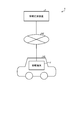
- FIG. 1 is a block diagram showing a configuration of an information providing system according to the first embodiment.
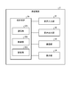
- FIG. 2 is a block diagram showing a configuration of an in-vehicle terminal.
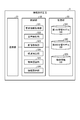
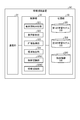
- FIG. 3 is a block diagram showing the configuration of the information providing device.
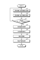
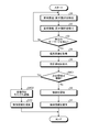
- FIG. 4 is a flowchart showing an information providing method.
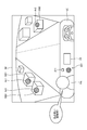
- FIG. 5 is a diagram illustrating an information providing method.
- FIG. 6 is a block diagram showing a configuration of an information providing device according to the second embodiment.
- FIG. 7 is a flowchart showing an information providing method.
- FIG. 8 is a diagram illustrating an information providing method.
- FIG. 9 is a block diagram showing a configuration of an in-vehicle terminal according to the third embodiment.
- FIG. 10 is a block diagram showing a configuration of an information providing device according to the third embodiment.
- FIG. 11 is a flowchart showing an information providing method.
- FIG. 12 is a block diagram showing a configuration of the information providing device according to the fourth embodiment.
- FIG. 13 is a flowchart showing an information providing method.
- FIG. 14 is a diagram illustrating an information providing method.
- FIG. 1 is a block diagram showing a configuration of an information providing system 1 according to the first embodiment.
- the information providing system 1 refers to object information (for example, the name of the object, etc.) regarding an object such as a building existing around the vehicle VE with respect to the occupant PA (see FIG. 5) of the moving vehicle VE (FIG. 1). ) Is a system that provides.
- the information providing system 1 includes an in-vehicle terminal 2 and an information providing device 3. Then, the in-vehicle terminal 2 and the information providing device 3 communicate with each other via the network NE (FIG. 1) which is a wireless communication network.
- the network NE FIG. 1 which is a wireless communication network.
- in-vehicle terminal 2 communicates with the information providing device 3
- a plurality of in-vehicle terminals 2 mounted on a plurality of vehicles may be used. Further, in order to provide object information to each of a plurality of occupants in one vehicle, a plurality of in-vehicle terminals 2 may be mounted in one vehicle.
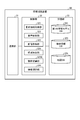
- FIG. 2 is a block diagram showing the configuration of the in-vehicle terminal 2.
- the in-vehicle terminal 2 is, for example, a stationary navigation device or a drive recorder installed in the vehicle VE.
- the in-vehicle terminal 2 is not limited to the navigation device or the drive recorder, and a portable terminal such as a smartphone used by the occupant PA of the vehicle VE may be adopted.
- the in-vehicle terminal 2 includes a voice input unit 21, a voice output unit 22, an imaging unit 23, a display unit 24, and a terminal body 25.
- the voice input unit 21 includes a microphone 211 (see FIG. 5) that inputs voice and converts it into an electric signal, and generates voice information by performing A / D (Analog / Digital) conversion or the like on the electric signal.
- the voice information generated by the voice input unit 21 is a digital signal.
- the voice input unit 21 outputs the voice information to the terminal body 25.
- the audio output unit 22 includes a speaker 221 (see FIG. 5), converts a digital audio signal input from the terminal body 25 into an analog audio signal by D / A (Digital / Analog) conversion, and the speaker 221 is used to convert the digital audio signal into an analog audio signal. Outputs audio according to the analog audio signal.
- the imaging unit 23 photographs the surroundings of the vehicle VE to generate a captured image. Then, the imaging unit 23 outputs the generated captured image to the terminal body 25.
- the display unit 24 is composed of a display using liquid crystal, organic EL (Electro Luminescence), or the like, and displays various images under the control of the terminal body 25.
- the terminal body 25 includes a communication unit 251, a control unit 252, and a storage unit 253.
- the communication unit 251 transmits and receives information to and from the information providing device 3 via the network NE under the control of the control unit 252.
- the control unit 252 is realized by executing various programs stored in the storage unit 253 by a controller such as a CPU (Central Processing Unit) or an MPU (Micro Processing Unit), and controls the operation of the entire vehicle-mounted terminal 2. do.
- the control unit 252 is not limited to the CPU and MPU, and may be configured by an integrated circuit such as an ASIC (Application Specific Integrated Circuit) or an FPGA (Field Programmable Gate Array).
- the storage unit 253 stores various programs executed by the control unit 252, data necessary for the control unit 252 to perform processing, and the like.
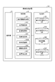
- FIG. 3 is a block diagram showing the configuration of the information providing device 3.
- the information providing device 3 is, for example, a server device. As shown in FIG. 3, the information providing device 3 includes a communication unit 31, a control unit 32, and a storage unit 33.
- the communication unit 31 transmits and receives information to and from the vehicle-mounted terminal 2 (communication unit 251) via the network NE under the control of the control unit 32.
- the control unit 32 is realized by executing various programs (including the information providing program according to the present embodiment) stored in the storage unit 33 by a controller such as a CPU or MPU, and the entire information providing device 3 is realized. Control the operation of.
- the control unit 32 is not limited to the CPU and MPU, and may be configured by an integrated circuit such as an ASIC or FPGA. As shown in FIG. 3, the control unit 32 includes a request information acquisition unit 321, a voice analysis unit 322, an image acquisition unit 323, an area extraction unit 324, an object recognition unit 325, and an information providing unit 326. Be prepared.
- the request information acquisition unit 321 acquires the request information requesting the provision of the object information from the occupant PA of the vehicle VE.
- the request information is voice information generated by the voice input unit 21 based on the voice input unit 21 taking in the words (voice) uttered by the occupant PA of the vehicle VE. be. That is, the request information acquisition unit 321 acquires the request information (voice information) from the in-vehicle terminal 2 via the communication unit 31.
- the voice analysis unit 322 analyzes the request information (voice information) acquired by the request information acquisition unit 321.
- the image acquisition unit 323 acquires the captured image generated by the image pickup unit 23 from the vehicle-mounted terminal 2 via the communication unit 31.
- the area extraction unit 324 extracts (predicts) the region of interest in the captured image acquired by the image acquisition unit 323 where the line of sight is concentrated (the line of sight is likely to be concentrated).
- the region extraction unit 324 extracts a region of interest in the captured image by using a so-called visual prominence technique. More specifically, the region extraction unit 324 extracts the region of interest in the captured image by image recognition (image recognition using AI (Artificial Intelligence)) using the first learning model shown below.
- an eye tracker is used to determine a region where the subject's line of sight is concentrated, an image in which the region is labeled in advance is used as a teacher image, and the region is machine-learned using the teacher image (for example,). It is a model obtained by deep learning etc.).
- the object recognition unit 325 recognizes an object included in the region of interest extracted by the region extraction unit 324 in the captured image.
- the object recognition unit 325 recognizes an object included in the region of interest in the captured image by image recognition (image recognition using AI) using the second learning model shown below.
- image recognition image recognition using AI
- the second learning model a photographed image of various objects such as animals, mountains, rivers, lakes, and facilities is used as a teacher image, and the features of the object are machine-learned (for example, deep layer) based on the teacher image. It is a model obtained by learning (learning, etc.).
- the information providing unit 326 provides object information regarding the object recognized by the object recognition unit 325. More specifically, the information providing unit 326 reads out the object information corresponding to the object recognized by the object recognition unit 325 from the object information DB (Data Base: database) 333 in the storage unit 33. Then, the information providing unit 326 transmits the object information to the in-vehicle terminal 2 via the communication unit 31.
- object information DB Data Base: database
- the storage unit 33 stores various programs executed by the control unit 32 (information providing program according to the present embodiment), as well as data and the like necessary for the control unit 32 to perform processing.
- the storage unit 33 includes a first learning model DB 331, a second learning model DB 332, and an object information DB 333.
- the first learning model DB331 stores the above-mentioned first learning model.
- the second learning model DB 332 stores the above-mentioned second learning model.
- the object information DB 333 stores the above-mentioned object information.
- the object information DB 333 stores a plurality of object information associated with various objects.
- the object information is information for explaining the object such as the name of the object, and is composed of character data, audio data, or image data.
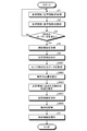
- FIG. 4 is a flowchart showing an information providing method.
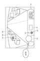
- FIG. 5 is a diagram illustrating an information providing method. Specifically, FIG. 5 is a diagram showing a captured image IM generated by the imaging unit 23 and acquired in step S4.
- FIG. 5 illustrates a case where the imaging unit 23 is installed in the vehicle VE so that the front of the vehicle VE is photographed from the inside of the vehicle VE through the windshield. Further, FIG. 5 illustrates a case where the occupant PA sitting in the passenger seat of the vehicle VE is included as a subject in the captured image IM. Further, FIG.
- the installation position of the imaging unit 23 is not limited to the above-mentioned installation position.
- the imaging unit 23 may be installed in the vehicle VE so that the left side, the right side, or the rear side of the vehicle VE is photographed from the inside of the vehicle VE, so that the surroundings of the vehicle VE are photographed.
- the imaging unit 23 may be installed outside the vehicle VE.
- the occupants of the vehicle according to the present embodiment include not only the occupants sitting in the passenger seat of the vehicle VE but also the occupants sitting in the driver's seat and the rear seat.
- the number of the imaging units 23 is not limited to one, and may be a plurality.
- the request information acquisition unit 321 acquires request information (voice information) from the vehicle-mounted terminal 2 via the communication unit 31 (step S1).
- the voice analysis unit 322 analyzes the request information (voice information) acquired in step S1 (step S2).
- the voice analysis unit 322 analyzes the request information (voice information) in the step S2, and as a result, determines whether or not the request information (voice information) includes a specific keyword (step).
- the specific keyword the occupant PA of the vehicle VE is a word requesting the provision of object information, and words such as "what", “what", “what is it", and "tell me” are used. It can be exemplified.
- step S3: No If it is determined that the specific keyword is not included (step S3: No), the control unit 32 returns to step S1.
- step S3: Yes the image acquisition unit 323 receives a captured image generated by the image pickup unit 23 from the vehicle-mounted terminal 2 via the communication unit 31.
- Acquire IM step S4: image acquisition step.
- the image acquisition unit 323 images the image from the in-vehicle terminal 2 via the communication unit 31 at the timing (step S3: Yes) when the occupant PA of the vehicle VE utters the word “what is that?”.
- the configuration is such that the captured image IM generated by the unit 23 is acquired, but the present invention is not limited to this.
- the information providing device 3 sequentially acquires captured images generated by the imaging unit 23 from the vehicle-mounted terminal 2 via the communication unit 31. Then, the image acquisition unit 323 captures the captured images acquired at the timing (step S3: Yes) when the occupant PA of the vehicle VE utters the word "what is that?" It may be configured to be acquired as a captured image used for the processing after step S4.
- the region extraction unit 324 determines the region of interest Ar1 (FIG. 5) in which the line of sight is concentrated in the captured image IM by image recognition using the first learning model stored in the first learning model DB331. Extract (step S5: region extraction step).
- the object recognition unit 325 uses the image recognition using the second learning model stored in the second learning model DB 332 to recognize the area of interest Ar1 extracted in step S5 in the captured image IM. Recognizes the object OB1 included in (step S6: object recognition step).
- Step S6 the information providing unit 326 reads the object information corresponding to the object OB1 recognized in step S6 from the object information DB 333, and transmits the object information to the in-vehicle terminal 2 via the communication unit 31 ( Step S7: Information provision step). Then, the control unit 252 controls the operation of at least one of the voice output unit 22 and the display unit 24, and transmits the object information transmitted from the information providing device 3 by at least one of voice, characters, and an image of the vehicle VE. Notify the occupant PA of. For example, when the object OB1 is "Moulin Rouge", the object information such as "That is Moulin Rouge. We are doing a gorgeous dance show at night.” Is sent to the occupant PA of the vehicle VE. Will be notified. Also, for example, when the object OB1 is not a building but an animal buffalo, a voice such as "That is a buffalo. Buffalo acts in a flock" is notified to the occupant PA of the vehicle VE as object information. Will be done.
- the information providing device 3 acquires a photographed image IM in which the surroundings of the vehicle VE are photographed, and extracts the region of interest Ar1 in which the line of sight is concentrated in the photographed image IM. Then, the information providing device 3 recognizes the object OB1 included in the region of interest Ar1 in the captured image IM, and transmits the object information related to the object OB1 to the in-vehicle terminal 2. As a result, the occupant PA of the vehicle VE who wants to obtain the object information regarding the object OB1 recognizes the object information regarding the object OB1 by being notified of the object information from the in-vehicle terminal 2.
- the information providing device 3 uses the so-called visual saliency technique to extract the region of interest Ar1 in which the line of sight is concentrated in the captured image IM. Therefore, even if the occupant PA of the vehicle VE does not point the object OB1 with a hand or a finger, the region including the object OB1 can be accurately extracted as the region of interest Ar1.
- the information providing device 3 provides the object information in response to the request information requesting the provision of the object information from the occupant PA of the vehicle VE. Therefore, the processing load of the information providing device 3 can be reduced as compared with the configuration in which the object information is always provided regardless of the required information.
- FIG. 6 is a block diagram showing a configuration of the information providing device 3A according to the second embodiment.
- the posture detecting unit 327 is connected to the control unit 32 with respect to the information providing device 3 (see FIG. 3) described in the above-described first embodiment. Function has been added. Further, in the information providing device 3A, the function of the object recognition unit 325 has been changed.
- the object recognition unit according to the second embodiment will be referred to as an object recognition unit 325A (see FIG. 6).
- a third learning model DB 334 (see FIG. 6) is added to the storage unit 33.
- the attitude detection unit 327 detects the attitude of the occupant PA of the vehicle VE.
- the posture detection unit 327 detects the posture by so-called skeleton detection. More specifically, the attitude detection unit 327 uses image recognition (image recognition using AI) using the third learning model shown below to capture the skeleton of the occupant PA of the vehicle VE included as a subject in the captured image IM. Is detected to detect the posture of the occupant PA.
- the third learning model an image in which the position of the joint point of the person is labeled in advance with respect to the photographed image of the person is used as a teacher image, and the position of the joint point is machine-learned based on the teacher image. This is a model obtained by performing deep learning (for example, deep learning). Then, the third learning model DB 334 stores the third learning model.
- the object recognition unit 325A has the same function as the object recognition unit 325 described in the first embodiment described above, and also has a function to be executed when a plurality of areas of interest are extracted in the captured image IM by the area extraction unit 324. (Hereinafter referred to as an additional function).
- the additional functions are as follows. That is, the object recognition unit 325A identifies any one of the plurality of attention areas based on the posture of the occupant PA detected by the attitude detection unit 327. Then, the object recognition unit 325A, similarly to the object recognition unit 325 described in the first embodiment described above, is subjected to image recognition using the second learning model to reach the specified region of interest in the captured image IM. Recognize the contained object.
- FIG. 7 is a flowchart showing an information providing method.
- FIG. 8 is a diagram illustrating an information providing method. Specifically, FIG. 8 is a diagram corresponding to FIG. 5, and shows a captured image IM generated by the imaging unit 23 and acquired in step S4.
- steps S6A1 to S6A3 are added to the information providing method (see FIG. 4) described in the above-described first embodiment. Therefore, in the following, only steps S6A1 to S6A3 will be mainly described.
- the steps S6A1 to S6A3 and S6 correspond to the object recognition step according to the present embodiment.
- Step S6A1 is executed after step S5. Specifically, in step S6A1, the control unit 32 determines whether or not there are a plurality of areas of interest extracted in step S5. Note that FIG. 8 illustrates a case where three regions of interest Ar1 to Ar3 are extracted in step S5. When it is determined that there is only one region of interest (step S6A1: No), the control unit 32 shifts to step S6 and the region of interest (for example, the region of interest as in the first embodiment described above). It recognizes an object (for example, an object OB1) included in Ar1).
- the region of interest for example, the region of interest as in the first embodiment described above. It recognizes an object (for example, an object OB1) included in Ar1).
- step S6A1 when the control unit 32 determines that there are a plurality of regions of interest (step S6A1: Yes), the control unit 32 shifts to step S6A2. Then, in step S6A2, the posture detection unit 327 recognizes the image using the third learning model stored in the third learning model DB 334, and the skeleton of the occupant PA of the vehicle VE included as a subject in the captured image IM. Is detected to detect the posture of the occupant PA.
- the object recognition unit 325A identifies the orientation DI (FIG. 8) of the face FA and finger FI of the occupant PA from the posture of the occupant PA detected in step S6A2. Then, the object recognition unit 325A identifies one attention region Ar2 located in the orientation DI with respect to the occupant PA among the three attention regions Ar1 to Ar3 extracted in step S5 in the captured image IM (step). S6A3). Then, after step S6A3, the control unit 32 shifts to step S6 and recognizes the object OB2 (FIG. 8) included in the one attention region Ar2.
- the information providing device 3A detects the postures of the occupant PAs of the vehicle VE when a plurality of attention areas Ar1 to Ar3 are extracted in the captured image IM, and based on the postures, a plurality of information providing devices 3A.
- One attention region Ar2 is specified from the attention regions Ar1 to Ar3. Then, the information providing device 3 recognizes the object OB2 included in the specified region of interest Ar2.
- the area including the object OB2 that the occupant PA of the vehicle VE wants to obtain the object information is accurately specified as the attention area Ar1. can do. Therefore, it is possible to provide appropriate object information to the occupant PA of the vehicle VE.
- the information providing device 3A detects the posture of the occupant PA of the vehicle VE by so-called skeleton detection. Therefore, the posture can be detected with high accuracy, and even when a plurality of attention areas Ar1 to Ar3 are extracted in the captured image IM, appropriate object information is provided to the occupant PA of the vehicle VE. Can be provided.
- FIG. 9 is a block diagram showing the configuration of the vehicle-mounted terminal 2B according to the third embodiment.
- the sensor unit 26 is added to the vehicle-mounted terminal 2 (see FIG. 2) described in the above-described first embodiment.
- the sensor unit 26 includes a rider 261 and a GNSS (Global Navigation Satellite System) sensor 262.
- GNSS Global Navigation Satellite System
- the rider 261 discretely measures the distance to an object existing in the outside world, recognizes the surface of the object as a three-dimensional point cloud, and generates point cloud data. As long as it is a sensor that can measure the distance to an object existing in the outside world, not only the rider 261 but also other outside world sensors such as a millimeter wave radar and sonar may be adopted.
- the GNSS sensor 262 uses GNSS to receive radio waves including positioning data transmitted from a navigation satellite. The positioning data is used to detect the absolute position of the vehicle VE from the latitude and longitude information and the like, and corresponds to the position information according to the present embodiment.
- the GNSS used may be, for example, GPS (Global Positioning System) or another system. Then, the sensor unit 26 outputs output data such as the point cloud data and the positioning data to the terminal body 25.
- FIG. 10 is a block diagram showing a configuration of the information providing device 3B according to the third embodiment. Further, in the information providing device 3B according to the third embodiment, the function of the object recognition unit 325 is changed with respect to the information providing device 3 (see FIG. 3) described in the above-described first embodiment. Hereinafter, for convenience of explanation, the object recognition unit according to the third embodiment will be referred to as an object recognition unit 325B (see FIG. 10). Further, in the information providing device 3B, the second learning model DB 332 is omitted, and the map DB 335 (see FIG. 10) is added to the storage unit 33.
- the map DB 335 stores the map data.
- the map data includes road data represented by a link corresponding to a road and a node corresponding to a connection portion (intersection) of the road, and each facility and the position of each facility (hereinafter referred to as facility position). Includes associated facility information, etc.
- the object recognition unit 325B acquires the output data of the sensor unit 26 (point group data generated by the rider 261 and positioning data received by the GNSS sensor 262) from the vehicle-mounted terminal 2 via the communication unit 31. Then, the object recognition unit 325B sets the region of interest extracted by the region extraction unit 324 in the captured image IM based on the output data, the captured image IM, and the map data stored in the map DB 335. Recognize the contained object.
- the object recognition unit 325B described above corresponds to a position information acquisition unit and a facility information acquisition unit in addition to the object recognition unit according to the present embodiment.
- FIG. 11 is a flowchart showing an information providing method.
- the information providing method (see FIG. 4) described in the above-described first embodiment is performed in steps S6B1 to S6B5 instead of step S6. Has been added. Therefore, in the following, only steps S6B1 to S6B5 will be mainly described.
- the steps S6B1 to S6B5 correspond to the object recognition step according to the present embodiment.
- Step S6B1 is executed after step S5. Specifically, in step S6B1, the object recognition unit 325B is generated by the output data of the sensor unit 26 (point cloud data generated by the rider 261 and the GNSS sensor 262) from the vehicle-mounted terminal 2 via the communication unit 31. (Positioning data) is acquired. In FIG. 11, the object recognition unit 325B transmits the output data of the sensor unit 26 from the in-vehicle terminal 2 via the communication unit 31 at the timing (step S3: Yes) when the occupant PA of the vehicle VE issues a word including a specific keyword. Is configured to be acquired, but it is not limited to this.
- the information providing device 3B sequentially acquires the output data of the sensor unit 26 from the vehicle-mounted terminal 2 via the communication unit 31. Then, the object recognition unit 325B uses the output data acquired at the timing (step S3: Yes) when the occupant PA of the vehicle VE issues a word including a specific keyword among the output data acquired in this order in step S6B1. It may be configured to be acquired as output data used for subsequent processing.
- the object recognition unit 325B determines the position of the vehicle VE based on the output data (positioning data received by the GNSS sensor 262) acquired in step S6B1 and the map data stored in the map DB 335. Estimate (step S6B2). After step S6B2, the object recognition unit 325B estimates the position of the object included in the region of interest in the captured image IM extracted in step S5 (step S6B3). Here, the object recognition unit 325B pays attention to the output data (point cloud data) acquired in step S6B1, the position of the vehicle VE estimated in step S6B2, and the captured image IM extracted in step S5. The position of the object is estimated using the position of the area.
- the object recognition unit 325B acquires facility information including the facility position substantially the same as the position of the object estimated in step S6B3 from the map DB 335 (step S6B4).
- the object recognition unit 325B recognizes the facility included in the facility information acquired in step S6B4 as an object included in the region of interest in the captured image IM extracted in step S5 (step S6B5). Then, the control unit 32 shifts to step S7 after step S6B5.
- the information providing device 3B recognizes an object included in the region of interest in the captured image IM based on the position information (positioning data received by the GNSS sensor 262) and the facility information. In other words, the information providing device 3B recognizes an object included in the region of interest in the captured image IM based on the information (position information and facility information) widely used in the navigation device. Therefore, it is not necessary to provide the second learning model DB 332 described in the first embodiment described above, and the configuration of the information providing device 3B can be simplified.
- FIG. 12 is a block diagram showing a configuration of the information providing device 3C according to the fourth embodiment.
- the object recognition unit 325 and the information providing unit are opposed to the information providing device 3 (see FIG. 3) described in the above-described first embodiment.
- the function of 326 has been changed.
- the object recognition unit according to the fourth embodiment is referred to as the object recognition unit 325C (see FIG. 12)
- the information providing unit according to the fourth embodiment is referred to as the information providing unit 326C (see FIG. 12). ).
- the object recognition unit 325C has the same function as the object recognition unit 325 described in the first embodiment described above, and also has a function to be executed when a plurality of areas of interest are extracted in the captured image IM by the area extraction unit 324. (Hereinafter referred to as an additional function).
- the additional functions are as follows. That is, the object recognition unit 325C recognizes the objects included in the plurality of areas of interest in the captured image IM by image recognition using the second learning model.
- the information providing unit 326C has the same functions as the information providing unit 326 described in the first embodiment described above, and also has a function to be executed when a plurality of areas of interest are extracted in the captured image IM by the area extraction unit 324. (Hereinafter referred to as an additional function).
- the additional functions are as follows. That is, the information providing unit 326C identifies one object from each object recognized by the object recognition unit 325C based on the analysis result by the voice analysis unit 322 and the object information stored in the object information DB 333. Then, the information providing unit 326C transmits the object information corresponding to the specified one object to the in-vehicle terminal 2 via the communication unit 31.
- FIG. 13 is a flowchart showing an information providing method.
- FIG. 14 is a diagram illustrating an information providing method. Specifically, FIG. 14 is a diagram corresponding to FIG. 5, and shows a captured image IM generated by the imaging unit 23 and acquired in step S4.
- FIG. 14 illustrates a case where the occupant PA sitting in the passenger seat of the vehicle VE is uttering the word “what is that red building?”.
- steps S6C1, S6C2, and S7C are added to the information providing method (see FIG. 4) described in the above-described first embodiment. There is.
- steps S6C1, S6C2, and S7C will be mainly described.
- the steps S6C1 and S6C2 and step S6 correspond to the object recognition step according to the present embodiment, respectively.
- steps S7C and S7 correspond to the information providing steps according to the present embodiment, respectively.
- Step S6C1 is executed after step S5. Specifically, in step S6C1, the control unit 32 determines whether or not there are a plurality of areas of interest extracted in step S5, similarly to step S6A1 described in the second embodiment described above. Note that FIG. 14 illustrates a case where three regions of interest Ar1 to Ar3 are extracted in step S5, as in FIG. When it is determined that there is only one region of interest (step S6C1: No), the control unit 32 shifts to step S6 and the region of interest (for example, the region of interest as in the first embodiment described above). It recognizes an object (for example, an object OB1) included in Ar1).
- the region of interest for example, the region of interest as in the first embodiment described above. It recognizes an object (for example, an object OB1) included in Ar1).
- step S6C1 when it is determined that there are a plurality of regions of interest (step S6C1: Yes), the control unit 32 shifts to step S6C2. Then, the object recognition unit 325C has three attention regions Ar1 to Ar3 extracted in step S5 in the captured image IM by image recognition using the second learning model stored in the second learning model DB332. Each of the objects OB1 to OB3 included in the above is recognized (step S6C2).
- the information providing unit 326C executes step S7C. Specifically, the information providing unit 326C identifies one object from each object recognized in step S6C2 in step S7C.
- the information providing unit 326C corresponds to the attributes of the object included in the request information (voice information) and the object information OB1 to OB3 recognized in step S6C2 among the object information stored in the object information DB333.
- the one object is specified based on the three object information.
- the attribute of the object included in the request information (voice information) is generated by analyzing the request information (voice information) in step S2. For example, as shown in FIG.
- the word “red” and the word “building” are objects. It becomes an attribute.
- the attribute of an object is information indicating a color such as red, a shape such as a square, and a type of a building or the like.
- the information providing unit 326C refers to three object information corresponding to each object OB1 to OB3, and one object corresponding to the object information including the character data of "red” and "building” (for example,). , Object OB3) is identified. Further, the information providing unit 326C transmits the object information corresponding to the specified one object to the in-vehicle terminal 2 via the communication unit 31.
- the information providing device 3C extracts the plurality of attention areas Ar1 to Ar3 in the captured image IM, and based on the analysis result of the request information (voice information), the plurality of attention areas Ar1 It provides object information about one of the objects OB1 to OB3 included in each of Ar3. Therefore, even when a plurality of areas of interest Ar1 to Ar3 are extracted in the captured image IM, it is possible to accurately identify the object OB3 that the occupant PA of the vehicle VE wants to obtain the object information. Therefore, it is possible to provide appropriate object information to the occupant PA of the vehicle VE.
- the information providing devices 3, 3A to 3C according to the above-described first to fourth embodiments are triggered by the acquisition of request information (voice information) including a specific keyword, and are an image acquisition step, an area extraction step, and an object recognition step. , And each process such as the information provision step was executed.
- the information providing device according to the present embodiment may be configured to always execute each process without acquiring request information (voice information) including a specific keyword.
- the request information according to the present embodiment is not limited to voice information, but is operation information corresponding to the operation of the occupant PA of the vehicle VE to the operation unit such as the switch provided on the in-vehicle terminals 2 and 2B. It doesn't matter.
- all the configurations of the information providing devices 3, 3A to 3C may be provided in the in-vehicle terminals 2 and 2B.
- the in-vehicle terminals 2 and 2B correspond to the information providing device according to the present embodiment.
- a part of the functions of the control unit 32 in the information providing devices 3, 3A to 3C and a part of the storage unit 33 may be provided in the in-vehicle terminals 2 and 2B.
- the entire information providing system 1 corresponds to the information providing device according to the present embodiment.
Landscapes
- Engineering & Computer Science (AREA)
- Physics & Mathematics (AREA)
- General Physics & Mathematics (AREA)
- Theoretical Computer Science (AREA)
- Remote Sensing (AREA)
- Radar, Positioning & Navigation (AREA)
- Multimedia (AREA)
- Computer Vision & Pattern Recognition (AREA)
- Automation & Control Theory (AREA)
- Human Computer Interaction (AREA)
- Traffic Control Systems (AREA)
- Navigation (AREA)
- Image Analysis (AREA)
Abstract
Description
特許文献1に記載の対象物特定装置では、車両の乗員が手や指で指し示している指示方向に存在する地図上の施設等を対象物として特定している。
〔情報提供システムの概略構成〕
図1は、実施の形態1に係る情報提供システム1の構成を示すブロック図である。
情報提供システム1は、移動体である車両VE(図1)の乗員PA(図5参照)に対して、当該車両VEの周囲に存在する建物等の物体に関する物体情報(例えば当該物体の名称等)を提供するシステムである。この情報提供システム1は、図1に示すように、車載端末2と、情報提供装置3とを備える。そして、これら車載端末2及び情報提供装置3は、無線通信網であるネットワークNE(図1)を介して、通信を行う。
なお、情報提供装置3と通信を行う車載端末2としては、図1では1台である場合を例示しているが、複数の車両にそれぞれ搭載された複数台であっても構わない。また、1台の車両に乗車している複数の乗員に対してそれぞれ物体情報を提供するために、1台の車両に車載端末2が複数台、搭載されていても構わない。
図2は、車載端末2の構成を示すブロック図である。
車載端末2は、例えば、車両VEに設置される据え置き型のナビゲーション装置またはドライブレコーダーである。なお、車載端末2としては、ナビゲーション装置またはドライブレコーダーに限らず、車両VEの乗員PAが利用するスマートフォン等の携帯型端末を採用しても構わない。この車載端末2は、図2に示すように、音声入力部21と、音声出力部22と、撮像部23と、表示部24と、端末本体25とを備える。
音声出力部22は、スピーカ221(図5参照)を含み、端末本体25から入力したデジタルの音声信号をD/A(Digital/Analog)変換によってアナログの音声信号に変換し、当該スピーカ221から当該アナログの音声信号に応じた音声を出力する。
表示部24は、液晶または有機EL(Electro Luminescence)等を用いた表示ディスプレイで構成され、端末本体25による制御の下、各種の画像を表示する。
通信部251は、制御部252による制御の下、ネットワークNEを介して情報提供装置3との間で情報の送受信を行う。
制御部252は、CPU(Central Processing Unit)やMPU(Micro Processing Unit)等のコントローラによって、記憶部253に記憶された各種のプログラムが実行されることにより実現され、車載端末2全体の動作を制御する。なお、制御部252は、CPUやMPUに限らず、ASIC(Application Specific Integrated Circuit)やFPGA(Field Programmable Gate Array)等の集積回路によって構成されても構わない。
記憶部253は、制御部252が実行する各種のプログラムや、当該制御部252が処理を行うときに必要なデータ等を記憶する。
図3は、情報提供装置3の構成を示すブロック図である。
情報提供装置3は、例えば、サーバ装置である。この情報提供装置3は、図3に示すように、通信部31と、制御部32と、記憶部33とを備える。
制御部32は、CPUやMPU等のコントローラによって、記憶部33に記憶された各種のプログラム(本実施の形態に係る情報提供プログラムを含む)が実行されることにより実現され、情報提供装置3全体の動作を制御する。なお、制御部32は、CPUやMPUに限らず、ASICやFPGA等の集積回路によって構成されても構わない。この制御部32は、図3に示すように、要求情報取得部321と、音声解析部322と、画像取得部323と、領域抽出部324と、物体認識部325と、情報提供部326とを備える。
音声解析部322は、要求情報取得部321が取得した要求情報(音声情報)を解析する。
領域抽出部324は、画像取得部323にて取得された撮影画像内における視線が集中する(視線が集中し易い)注目領域を抽出(予測)する。本実施の形態1では、領域抽出部324は、所謂、視覚的顕著性技術を利用して撮影画像内における注目領域を抽出する。より具体的に、領域抽出部324は、以下に示す第1の学習モデルを用いた画像認識(AI(Artificial Intelligence)を用いた画像認識)により、撮影画像内における注目領域を抽出する。
当該第1の学習モデルは、アイトラッカを用いて被験者の視線が集中する領域を判別し、当該領域が予めラベリングされた画像を教師画像とし、当該教師画像を利用して当該領域を機械学習(例えば深層学習等)することにより得られたモデルである。
当該第2の学習モデルは、動物、山、川、湖、及び施設等の各種の物体が撮影された撮影画像を教師画像とし、当該教師画像に基づいて当該物体の特徴を機械学習(例えば深層学習等)することにより得られたモデルである。
第1の学習モデルDB331は、上述した第1の学習モデルを記憶する。
第2の学習モデルDB332は、上述した第2の学習モデルを記憶する。
物体情報DB333は、上述した物体情報を記憶する。ここで、物体情報DB333には、各種の物体に関連付けられた複数の物体情報が記憶されている。当該物体情報としては、物体の名称等の当該物体を説明する情報であって、文字データ、音声データ、あるいは、画像データによって構成されている。
次に、情報提供装置3(制御部32)が実行する情報提供方法について説明する。
図4は、情報提供方法を示すフローチャートである。図5は、情報提供方法を説明する図である。具体的に、図5は、撮像部23にて生成され、ステップS4にて取得される撮影画像IMを示す図である。ここで、図5では、車両VE内からフロントガラスを介して当該車両VEの前方が撮影されるように当該車両VE内に撮像部23を設置した場合を例示している。また、図5では、撮影画像IM内に車両VEの助手席に座った乗員PAが被写体として含まれる場合を例示している。さらに、図5では、当該乗員PAが「あれ何?」という言葉を発している場合を例示している。
なお、撮像部23の設置位置としては、上述した設置位置に限らない。例えば、車両VE内から当該車両VEの左側方や右側方、あるいは、後方が撮影されるように当該車両VE内に撮像部23を設置してもよく、車両VEの周囲が撮影されるように当該車両VE外に撮像部23を設置しても構わない。また、本実施の形態に係る車両の乗員としては、車両VEの助手席に座った乗員に限らず、運転席や後部座席に座った乗員等を含むものである。また、撮像部23の数としては、一つに限らず、複数としても構わない。
ステップS1の後、音声解析部322は、当該ステップS1にて取得された要求情報(音声情報)を解析する(ステップS2)。
ステップS2の後、音声解析部322は、当該ステップS2にて要求情報(音声情報)を解析した結果、当該要求情報(音声情報)に特定のキーワードが含まれているか否かを判定する(ステップS3)。
ここで、当該特定のキーワードとしては、車両VEの乗員PAが物体情報の提供を要求する言葉であり、「なに」、「なんですか」、「なんだろう」、「おしえて」等の言葉を例示することができる。
一方、特定のキーワードが含まれていると判定された場合(ステップS3:Yes)には、画像取得部323は、通信部31を介して車載端末2から撮像部23にて生成された撮影画像IMを取得する(ステップS4:画像取得ステップ)。
なお、図4及び図5では、車両VEの乗員PAが「あれ何?」との言葉を発したタイミング(ステップS3:Yes)で画像取得部323が通信部31を介して車載端末2から撮像部23にて生成された撮影画像IMを取得する構成としているが、これに限らない。例えば、情報提供装置3は、通信部31を介して車載端末2から撮像部23にて生成された撮影画像を順次、取得する。そして、画像取得部323は、当該順次、取得された撮影画像のうち、車両VEの乗員PAが「あれ何?」との言葉を発したタイミング(ステップS3:Yes)で取得された撮影画像をステップS4以降の処理に用いる撮影画像として取得する構成としても構わない。
ステップS5の後、物体認識部325は、第2の学習モデルDB332に記憶された第2の学習モデルを用いた画像認識により、撮影画像IM内において、当該ステップS5にて抽出された注目領域Ar1に含まれる物体OB1を認識する(ステップS6:物体認識ステップ)。
ステップS6の後、情報提供部326は、物体情報DB333から当該ステップS6にて認識された物体OB1に対応する物体情報を読み出し、通信部31を介して車載端末2に当該物体情報を送信する(ステップS7:情報提供ステップ)。そして、制御部252は、音声出力部22及び表示部24の少なくともいずれかの動作を制御し、情報提供装置3から送信された物体情報を音声、文字、及び画像の少なくともいずれかによって、車両VEの乗員PAに対して報知する。例えば、物体OB1が「ムーラン・ルージュ」である場合には、物体情報として「あれはムーラン・ルージュです。華やかなダンスショーを夜にやっています。」等の音声が車両VEの乗員PAに対して報知される。また、例えば、物体OB1が建物ではなく動物のバッファローである場合には、物体情報として「あれはバッファローです。バッファローは群れで行動します。」等の音声が車両VEの乗員PAに対して報知される。
本実施の形態1に係る情報提供装置3は、車両VEの周囲を撮影した撮影画像IMを取得し、当該撮影画像IM内における視線が集中する注目領域Ar1を抽出する。そして、情報提供装置3は、撮影画像IM内における注目領域Ar1に含まれる物体OB1を認識し、当該物体OB1に関する物体情報を車載端末2に送信する。その結果、物体OB1に関する物体情報を得ることを望む車両VEの乗員PAは、車載端末2から物体情報が報知されることで、当該物体OB1に関する当該物体情報を認識する。
したがって、物体OB1に関する物体情報を得ることを望む車両VEの乗員PAに対して、従来のように当該物体OB1を手や指で指し示すという作業を行わせる必要がなく、利便性を向上させることができる。
次に、本実施の形態2について説明する。
以下の説明では、上述した実施の形態1と同様の構成には同一符号を付し、その詳細な説明は省略または簡略化する。
図6は、実施の形態2に係る情報提供装置3Aの構成を示すブロック図である。
本実施の形態2に係る情報提供装置3Aでは、図6に示すように、上述した実施の形態1で説明した情報提供装置3(図3参照)に対して、制御部32に姿勢検出部327の機能が追加されている。また、情報提供装置3Aでは、物体認識部325の機能が変更されている。以下では、説明の便宜上、本実施の形態2に係る物体認識部を物体認識部325A(図6参照)と記載する。さらに、情報提供装置3Aでは、記憶部33に第3の学習モデルDB334(図6参照)が追加されている。
当該第3の学習モデルは、人が撮影された撮影画像に対して当該人の関節点の位置が予めラベリングされた画像を教師画像とし、当該教師画像に基づいて当該関節点の位置を機械学習(例えば深層学習等)することにより得られたモデルである。
そして、第3の学習モデルDB334は、当該第3の学習モデルを記憶する。
すなわち、物体認識部325Aは、姿勢検出部327にて検出された乗員PAの姿勢に基づいて、当該複数の注目領域のうちいずれか一つの注目領域を特定する。そして、物体認識部325Aは、上述した実施の形態1で説明した物体認識部325と同様に、第2の学習モデルを用いた画像認識により、撮影画像IM内における当該特定した一つの注目領域に含まれる物体を認識する。
図7は、情報提供方法を示すフローチャートである。図8は、情報提供方法を説明する図である。具体的に、図8は、図5に対応した図であって、撮像部23にて生成され、ステップS4にて取得される撮影画像IMを示している。
本実施の形態2に係る情報提供方法では、図7に示すように、上述した実施の形態1で説明した情報提供方法(図4参照)に対して、ステップS6A1~S6A3が追加されている。このため、以下では、ステップS6A1~S6A3のみを主に説明する。当該ステップS6A1~S6A3,S6は、本実施の形態に係る物体認識ステップに相当する。
具体的に、制御部32は、ステップS6A1において、ステップS5にて抽出された注目領域が複数であるか否かを判断する。なお、図8では、ステップS5において、3つの注目領域Ar1~Ar3が抽出された場合を例示している。
注目領域が一つであると判断した場合(ステップS6A1:No)には、制御部32は、ステップS6に移行し、当該一つの注目領域(例えば、上述した実施の形態1と同様に注目領域Ar1)に含まれる物体(例えば、物体OB1)を認識する。
そして、姿勢検出部327は、ステップS6A2において、第3の学習モデルDB334に記憶された第3の学習モデルを用いた画像認識により、撮影画像IM内に被写体として含まれる車両VEの乗員PAの骨格を検知することで当該乗員PAの姿勢を検出する。
そして、ステップS6A3の後、制御部32は、ステップS6に移行し、当該一つの注目領域Ar2に含まれる物体OB2(図8)を認識する。
本実施の形態2に係る情報提供装置3Aは、撮影画像IM内に複数の注目領域Ar1~Ar3を抽出した場合に、車両VEの乗員PAの姿勢を検出し、当該姿勢に基づいて、複数の注目領域Ar1~Ar3から一つの注目領域Ar2を特定する。そして、情報提供装置3は、当該特定した注目領域Ar2に含まれる物体OB2を認識する。
このため、撮影画像IM内に複数の注目領域Ar1~Ar3を抽出した場合であっても、車両VEの乗員PAが物体情報を得ることを望む物体OB2を含む領域を注目領域Ar1として精度良く特定することができる。したがって、車両VEの乗員PAに対して、適切な物体情報を提供することができる。
次に、本実施の形態3について説明する。
以下の説明では、上述した実施の形態1と同様の構成には同一符号を付し、その詳細な説明は省略または簡略化する。
図9は、実施の形態3に係る車載端末2Bの構成を示すブロック図である。
本実施の形態3に係る車載端末2Bでは、図9に示すように、上述した実施の形態1で説明した車載端末2(図2参照)に対して、センサ部26が追加されている。
センサ部26は、図9に示すように、ライダ261と、GNSS(Global Navigation Satellite System)センサ262とを備える。
ライダ261は、外界に存在する物体までの距離を離散的に測定し、当該物体の表面を3次元の点群として認識し、点群データを生成する。なお、外界に存在する物体までの距離を測定することができるセンサであれば、ライダ261に限らず、ミリ波レーダ及びソナー等の他の外界センサを採用しても構わない。
GNSSセンサ262は、GNSSを利用して、航法衛星から送信された測位用データを含む電波を受信する。当該測位用データは、緯度及び経度情報等から車両VEの絶対的な位置を検出するために用いられ、本実施の形態に係る位置情報に相当する。なお、利用されるGNSSは、例えば、GPS(Global Positioning System)であってもよいし、他のシステムであっても構わない。
そして、センサ部26は、当該点群データや当該測位用データ等の出力データを端末本体25に出力する。
また、本実施の形態3に係る情報提供装置3Bでは、上述した実施の形態1で説明した情報提供装置3(図3参照)に対して、物体認識部325の機能が変更されている。以下では、説明の便宜上、本実施の形態3に係る物体認識部を物体認識部325B(図10参照)と記載する。また、情報提供装置3Bでは、第2の学習モデルDB332が省略されているとともに、記憶部33に地図DB335(図10参照)が追加されている。
物体認識部325Bは、通信部31を介して車載端末2からセンサ部26の出力データ(ライダ261にて生成された点群データ、GNSSセンサ262にて受信した測位用データ)を取得する。そして、物体認識部325Bは、当該出力データと、撮影画像IMと、地図DB335に記憶された地図データとに基づいて、当該撮影画像IM内において、領域抽出部324にて抽出された注目領域に含まれる物体を認識する。
以上説明した物体認識部325Bは、本実施の形態に係る物体認識部の他、位置情報取得部及び施設情報取得部に相当する。
図11は、情報提供方法を示すフローチャートである。
本実施の形態3に係る情報提供方法では、図11に示すように、上述した実施の形態1で説明した情報提供方法(図4参照)に対して、ステップS6の代わりに、ステップS6B1~S6B5が追加されている。このため、以下では、ステップS6B1~S6B5のみを主に説明する。当該ステップS6B1~S6B5は、本実施の形態に係る物体認識ステップに相当する。
具体的に、物体認識部325Bは、ステップS6B1において、通信部31を介して車載端末2からセンサ部26の出力データ(ライダ261にて生成された点群データ、GNSSセンサ262にて生成された測位用データ)を取得する。
なお、図11では、車両VEの乗員PAが特定のキーワードを含む言葉を発したタイミング(ステップS3:Yes)で物体認識部325Bが通信部31を介して車載端末2からセンサ部26の出力データを取得する構成としているが、これに限らない。例えば、情報提供装置3Bは、通信部31を介して車載端末2からセンサ部26の出力データを順次、取得する。そして、物体認識部325Bは、当該順次、取得された出力データのうち、車両VEの乗員PAが特定のキーワードを含む言葉を発したタイミング(ステップS3:Yes)で取得された出力データをステップS6B1以降の処理に用いる出力データとして取得する構成としても構わない。
ステップS6B2の後、物体認識部325Bは、ステップS5にて抽出された撮影画像IMにおける注目領域に含まれる物体の位置を推定する(ステップS6B3)。ここで、物体認識部325Bは、ステップS6B1にて取得した出力データ(点群データ)と、ステップS6B2にて推定した車両VEの位置と、ステップS5にて抽出された撮影画像IM内での注目領域の位置とを利用して、当該物体の位置を推定する。
ステップS6B4の後、物体認識部325Bは、ステップS6B4にて取得した施設情報に含まれる施設をステップS5にて抽出された撮影画像IMにおける注目領域に含まれる物体として認識する(ステップS6B5)。
そして、制御部32は、ステップS6B5の後、ステップS7に移行する。
本実施の形態3に係る情報提供装置3Bは、位置情報(GNSSセンサ262にて受信した測位用データ)及び施設情報に基づいて、撮影画像IM内における注目領域に含まれる物体を認識する。言い換えれば、情報提供装置3Bは、ナビゲーション装置において汎用されている情報(位置情報及び施設情報)に基づいて、撮影画像IM内における注目領域に含まれる物体を認識する。
このため、上述した実施の形態1で説明した第2の学習モデルDB332を設ける必要がなく、情報提供装置3Bの構成の簡素化を図ることができる。
次に、本実施の形態4について説明する。
以下の説明では、上述した実施の形態1と同様の構成には同一符号を付し、その詳細な説明は省略または簡略化する。
図12は、実施の形態4に係る情報提供装置3Cの構成を示すブロック図である。
本実施の形態4に係る情報提供装置3Cでは、図12に示すように、上述した実施の形態1で説明した情報提供装置3(図3参照)に対して、物体認識部325及び情報提供部326の機能が変更されている。以下では、説明の便宜上、本実施の形態4に係る物体認識部を物体認識部325C(図12参照)と記載し、本実施の形態4に係る情報提供部を情報提供部326C(図12参照)と記載する。
すなわち、物体認識部325Cは、第2の学習モデルを用いた画像認識により、撮影画像IM内における当該複数の注目領域にそれぞれ含まれる物体をそれぞれ認識する。
すなわち、情報提供部326Cは、音声解析部322による解析結果と、物体情報DB333に記憶された物体情報とに基づいて、物体認識部325Cにて認識された各物体から一つの物体を特定する。そして、情報提供部326Cは、通信部31を介して車載端末2に当該特定した一つの物体に対応する物体情報を送信する。
図13は、情報提供方法を示すフローチャートである。図14は、情報提供方法を説明する図である。具体的に、図14は、図5に対応した図であって、撮像部23にて生成され、ステップS4にて取得される撮影画像IMを示している。ここで、図14では、図5の例とは異なり、車両VEの助手席に座った乗員PAが「あの赤い建物何?」という言葉を発している場合を例示している。
本実施の形態4に係る情報提供方法では、図13に示すように、上述した実施の形態1で説明した情報提供方法(図4参照)に対して、ステップS6C1,S6C2,S7Cが追加されている。このため、以下では、ステップS6C1,S6C2,S7Cのみを主に説明する。当該ステップS6C1,S6C2とステップS6とは、それぞれ本実施の形態に係る物体認識ステップに相当する。また、当該ステップS7CとステップS7とは、それぞれ本実施の形態に係る情報提供ステップに相当する。
具体的に、制御部32は、ステップS6C1において、上述した実施の形態2で説明したステップS6A1と同様に、ステップS5にて抽出された注目領域が複数であるか否かを判断する。なお、図14では、図8と同様に、ステップS5において、3つの注目領域Ar1~Ar3が抽出された場合を例示している。
注目領域が一つであると判断した場合(ステップS6C1:No)には、制御部32は、ステップS6に移行し、当該一つの注目領域(例えば、上述した実施の形態1と同様に注目領域Ar1)に含まれる物体(例えば、物体OB1)を認識する。
そして、物体認識部325Cは、第2の学習モデルDB332に記憶された第2の学習モデルを用いた画像認識により、撮影画像IM内において、ステップS5にて抽出された3つの注目領域Ar1~Ar3にそれぞれ含まれる物体OB1~OB3をそれぞれ認識する(ステップS6C2)。
具体的に、情報提供部326Cは、ステップS7Cにおいて、ステップS6C2にて認識された各物体から一つの物体を特定する。ここで、情報提供部326Cは、要求情報(音声情報)に含まれる物体の属性と、物体情報DB333に記憶された物体情報のうち、ステップS6C2にて認識された各物体OB1~OB3に対応する3つの物体情報とに基づいて、当該一つの物体を特定する。
なお、要求情報(音声情報)に含まれる物体の属性とは、ステップS2にて当該要求情報(音声情報)が解析されることで生成されるものである。例えば、図14に示すように、車両VEの乗員PAが「あの赤い建物何?」との言葉を発した場合には、「赤い」との言葉と、「建物」との言葉とが物体の属性となる。具体的に、物体の属性とは、赤等の色、四角等の形状、建物等の種別を示す情報である。そして、情報提供部326Cは、ステップS7Cにおいて、各物体OB1~OB3に対応する3つの物体情報を参照し、「赤い」及び「建物」の文字データを含む物体情報に対応する一つの物体(例えば、物体OB3)を特定する。また、情報提供部326Cは、通信部31を介して車載端末2に当該特定した一つの物体に対応する物体情報を送信する。
本実施の形態4に係る情報提供装置3Cは、撮影画像IM内に複数の注目領域Ar1~Ar3を抽出した場合に、要求情報(音声情報)の解析結果に基づいて、当該複数の注目領域Ar1~Ar3にそれぞれ含まれる物体OB1~OB3のうち一つの物体に関する物体情報を提供する。
このため、撮影画像IM内に複数の注目領域Ar1~Ar3を抽出した場合であっても、車両VEの乗員PAが物体情報を得ることを望む物体OB3を精度良く特定することができる。したがって、車両VEの乗員PAに対して、適切な物体情報を提供することができる。
ここまで、本発明を実施するための形態を説明してきたが、本発明は上述した実施の形態1~4によってのみ限定されるべきものではない。
上述した実施の形態1~4に係る情報提供装置3,3A~3Cは、特定のキーワードを含む要求情報(音声情報)を取得したことをトリガとして、画像取得ステップ、領域抽出ステップ、物体認識ステップ、及び情報提供ステップ等の各処理を実行していた。しかしながら、本実施の形態に係る情報提供装置としては、特定のキーワードを含む要求情報(音声情報)を取得しなくても、常時、当該各処理を実行する構成としても構わない。また、本実施の形態に係る要求情報としては、音声情報に限らず、車両VEの乗員PAによる車載端末2,2Bに設けられたスイッチ等の操作部への操作に応じた操作情報であっても構わない。
321 要求情報取得部
322 音声解析部
323 画像取得部
324 領域抽出部
325,325A~325C 物体認識部
326,326C 情報提供部
327 姿勢検出部
Claims (9)
- 移動体の周囲を撮影した撮影画像を取得する画像取得部と、
前記撮影画像内における視線が集中する注目領域を抽出する領域抽出部と、
前記撮影画像内における前記注目領域に含まれる物体を認識する物体認識部と、
前記注目領域に含まれる物体に関する物体情報を提供する情報提供部とを備える
ことを特徴とする情報提供装置。 - 前記移動体内における乗員の姿勢を検出する姿勢検出部をさらに備え、
前記領域抽出部は、
複数の前記注目領域を抽出し、
前記物体認識部は、
前記姿勢に基づいて、前記複数の注目領域のうちいずれか一つの注目領域を特定し、当該特定した注目領域に含まれる物体を認識する
ことを特徴とする請求項1に記載の情報提供装置。 - 前記撮影画像は、
前記移動体内における乗員を被写体として含み、
前記姿勢検出部は、
前記撮影画像に基づいて、前記乗員の骨格を検知することで前記姿勢を検出する
ことを特徴とする請求項2に記載の情報提供装置。 - 前記移動体の位置に関する位置情報を取得する位置情報取得部と、
施設に関する施設情報を取得する施設情報取得部とをさらに備え、
前記物体認識部は、
前記位置情報及び前記施設情報に基づいて、前記注目領域に含まれる物体を認識する
ことを特徴とする請求項1~3のいずれか一つに記載の情報提供装置。 - 前記移動体内における乗員からの前記物体情報の提供を要求する要求情報を取得する要求情報取得部をさらに備え、
前記情報提供部は、
前記要求情報に応じて前記物体情報を提供する
ことを特徴とする請求項1~4のいずれか一つに記載の情報提供装置。 - 前記要求情報は、
前記乗員が発した音声に関する音声情報であり、
前記音声情報を解析する音声解析部をさらに備え、
前記領域抽出部は、
複数の前記注目領域を抽出し、
前記物体認識部は、
前記複数の注目領域に含まれる物体をそれぞれ認識し、
前記情報提供部は、
前記音声情報の解析結果に基づいて、前記複数の注目領域にそれぞれ含まれる物体のうちいずれか一つの物体に関する前記物体情報を提供する
ことを特徴とする請求項5に記載の情報提供装置。 - 情報提供装置が実行する情報提供方法であって、
移動体の周囲を撮影した撮影画像を取得する画像取得ステップと、
前記撮影画像内における視線が集中する注目領域を抽出する領域抽出ステップと、
前記撮影画像内における前記注目領域に含まれる物体を認識する物体認識ステップと、
前記注目領域に含まれる物体に関する物体情報を提供する情報提供ステップとを含む
ことを特徴とする情報提供方法。 - 移動体の周囲を撮影した撮影画像を取得する画像取得ステップと、
前記撮影画像内における視線が集中する注目領域を抽出する領域抽出ステップと、
前記撮影画像内における前記注目領域に含まれる物体を認識する物体認識ステップと、
前記注目領域に含まれる物体に関する物体情報を提供する情報提供ステップと
をコンピュータに実行させるための情報提供プログラム。 - 移動体の周囲を撮影した撮影画像を取得する画像取得ステップと、
前記撮影画像内における視線が集中する注目領域を抽出する領域抽出ステップと、
前記撮影画像内における前記注目領域に含まれる物体を認識する物体認識ステップと、
前記注目領域に含まれる物体に関する物体情報を提供する情報提供ステップとをコンピュータに実行させるための情報提供プログラムを記憶した
ことを特徴とする記憶媒体。
Priority Applications (5)
| Application Number | Priority Date | Filing Date | Title |
|---|---|---|---|
| JP2021573116A JPWO2021149594A1 (ja) | 2020-01-21 | 2021-01-14 | |
| EP21744610.3A EP4095490B1 (en) | 2020-01-21 | 2021-01-14 | Information provision device, information provision method, information provision program, and recording medium |
| US17/772,649 US20220405955A1 (en) | 2020-01-21 | 2021-01-14 | Information providing apparatus, information providing method, information providing program, and storage medium |
| JP2023094598A JP2023111989A (ja) | 2020-01-21 | 2023-06-08 | 情報提供装置 |
| JP2025074280A JP2025105844A (ja) | 2020-01-21 | 2025-04-28 | 情報提供装置、情報提供方法、情報提供プログラム及び記憶媒体 |
Applications Claiming Priority (2)
| Application Number | Priority Date | Filing Date | Title |
|---|---|---|---|
| JP2020-007866 | 2020-01-21 | ||
| JP2020007866 | 2020-01-21 |
Publications (1)
| Publication Number | Publication Date |
|---|---|
| WO2021149594A1 true WO2021149594A1 (ja) | 2021-07-29 |
Family
ID=76992742
Family Applications (1)
| Application Number | Title | Priority Date | Filing Date |
|---|---|---|---|
| PCT/JP2021/001126 Ceased WO2021149594A1 (ja) | 2020-01-21 | 2021-01-14 | 情報提供装置、情報提供方法、情報提供プログラム及び記憶媒体 |
Country Status (4)
| Country | Link |
|---|---|
| US (1) | US20220405955A1 (ja) |
| EP (1) | EP4095490B1 (ja) |
| JP (3) | JPWO2021149594A1 (ja) |
| WO (1) | WO2021149594A1 (ja) |
Families Citing this family (7)
| Publication number | Priority date | Publication date | Assignee | Title |
|---|---|---|---|---|
| US12493705B2 (en) | 2022-08-31 | 2025-12-09 | Snap Inc. | Selective collaborative object access based on timestamp |
| US12299150B2 (en) | 2022-08-31 | 2025-05-13 | Snap Inc. | Selective collaborative object access |
| US12148114B2 (en) | 2022-08-31 | 2024-11-19 | Snap Inc. | Real-world responsiveness of a collaborative object |
| US12361106B2 (en) | 2022-08-31 | 2025-07-15 | Snap Inc. | Authenticating a selective collaborative object |
| US12019773B2 (en) | 2022-08-31 | 2024-06-25 | Snap Inc. | Timelapse of generating a collaborative object |
| US12505239B2 (en) | 2022-08-31 | 2025-12-23 | Snap Inc. | Collaborative object associated with a geographical location |
| US12079395B2 (en) | 2022-08-31 | 2024-09-03 | Snap Inc. | Scissor hand gesture for a collaborative object |
Citations (6)
| Publication number | Priority date | Publication date | Assignee | Title |
|---|---|---|---|---|
| JPH06251287A (ja) * | 1993-02-23 | 1994-09-09 | Mitsubishi Electric Corp | 運転支援システム |
| JP2004030212A (ja) * | 2002-06-25 | 2004-01-29 | Toyota Central Res & Dev Lab Inc | 車両用情報提供装置 |
| JP2006251298A (ja) * | 2005-03-10 | 2006-09-21 | Nissan Motor Co Ltd | 音声入力装置および音声入力方法 |
| JP2007080060A (ja) | 2005-09-15 | 2007-03-29 | Matsushita Electric Ind Co Ltd | 対象物特定装置 |
| JP2014207614A (ja) * | 2013-04-15 | 2014-10-30 | オムロン株式会社 | 画像処理装置、画像処理方法、画像処理プログラムおよび記録媒体 |
| WO2014192103A1 (ja) * | 2013-05-29 | 2014-12-04 | 三菱電機株式会社 | 情報表示装置 |
Family Cites Families (11)
| Publication number | Priority date | Publication date | Assignee | Title |
|---|---|---|---|---|
| JP4604597B2 (ja) * | 2004-07-30 | 2011-01-05 | トヨタ自動車株式会社 | 状態推定装置、状態推定方法、及びそれを用いた情報提供装置、情報提供方法 |
| JPWO2014077046A1 (ja) * | 2012-11-13 | 2017-01-05 | ソニー株式会社 | 画像表示装置及び画像表示方法、移動体装置、画像表示システム、並びにコンピューター・プログラム |
| KR20140070861A (ko) * | 2012-11-28 | 2014-06-11 | 한국전자통신연구원 | 멀티 모달 hmi 제어 장치 및 방법 |
| JP6033804B2 (ja) * | 2014-02-18 | 2016-11-30 | 本田技研工業株式会社 | 車載機器操作装置 |
| KR101708676B1 (ko) * | 2015-05-14 | 2017-03-08 | 엘지전자 주식회사 | 운전자 보조 장치 및 그 제어방법 |
| US10043084B2 (en) * | 2016-05-27 | 2018-08-07 | Toyota Jidosha Kabushiki Kaisha | Hierarchical context-aware extremity detection |
| EP3572737B1 (en) * | 2017-01-17 | 2023-04-12 | Toshiba Carrier Corporation | Air conditioner |
| JP7062930B2 (ja) * | 2017-12-01 | 2022-05-09 | 株式会社アイシン | 制御装置およびプログラム |
| US10597042B2 (en) * | 2018-03-27 | 2020-03-24 | Intel Corporation | User gesture directed object detection and recognition in a vehicle |
| US10782777B2 (en) * | 2018-11-29 | 2020-09-22 | International Business Machines Corporation | Real-time alteration of standard video and immersive video for virtual reality |
| JP7418189B2 (ja) * | 2019-11-21 | 2024-01-19 | 日産自動車株式会社 | 表示画像生成装置及び表示画像生成方法 |
-
2021
- 2021-01-14 WO PCT/JP2021/001126 patent/WO2021149594A1/ja not_active Ceased
- 2021-01-14 JP JP2021573116A patent/JPWO2021149594A1/ja not_active Ceased
- 2021-01-14 EP EP21744610.3A patent/EP4095490B1/en active Active
- 2021-01-14 US US17/772,649 patent/US20220405955A1/en active Pending
-
2023
- 2023-06-08 JP JP2023094598A patent/JP2023111989A/ja active Pending
-
2025
- 2025-04-28 JP JP2025074280A patent/JP2025105844A/ja active Pending
Patent Citations (6)
| Publication number | Priority date | Publication date | Assignee | Title |
|---|---|---|---|---|
| JPH06251287A (ja) * | 1993-02-23 | 1994-09-09 | Mitsubishi Electric Corp | 運転支援システム |
| JP2004030212A (ja) * | 2002-06-25 | 2004-01-29 | Toyota Central Res & Dev Lab Inc | 車両用情報提供装置 |
| JP2006251298A (ja) * | 2005-03-10 | 2006-09-21 | Nissan Motor Co Ltd | 音声入力装置および音声入力方法 |
| JP2007080060A (ja) | 2005-09-15 | 2007-03-29 | Matsushita Electric Ind Co Ltd | 対象物特定装置 |
| JP2014207614A (ja) * | 2013-04-15 | 2014-10-30 | オムロン株式会社 | 画像処理装置、画像処理方法、画像処理プログラムおよび記録媒体 |
| WO2014192103A1 (ja) * | 2013-05-29 | 2014-12-04 | 三菱電機株式会社 | 情報表示装置 |
Non-Patent Citations (1)
| Title |
|---|
| See also references of EP4095490A4 |
Also Published As
| Publication number | Publication date |
|---|---|
| JP2025105844A (ja) | 2025-07-10 |
| EP4095490A1 (en) | 2022-11-30 |
| JPWO2021149594A1 (ja) | 2021-07-29 |
| US20220405955A1 (en) | 2022-12-22 |
| EP4095490A4 (en) | 2024-02-21 |
| EP4095490B1 (en) | 2026-03-04 |
| JP2023111989A (ja) | 2023-08-10 |
Similar Documents
| Publication | Publication Date | Title |
|---|---|---|
| WO2021149594A1 (ja) | 情報提供装置、情報提供方法、情報提供プログラム及び記憶媒体 | |
| JPWO2021149594A5 (ja) | ||
| US11449727B2 (en) | Method, storage medium and electronic device for detecting vehicle crashes | |
| CN107924632B (zh) | 信息处理设备、信息处理方法和程序 | |
| CN111599356B (zh) | 智能体系统、信息处理装置、信息处理方法及存储介质 | |
| JP7020434B2 (ja) | 画像処理装置、および画像処理方法、並びにプログラム | |
| KR20210098972A (ko) | 정보 처리 장치, 정보 처리 방법, 프로그램, 이동체 제어 장치 및 이동체 | |
| US20180144622A1 (en) | Parking Notification Systems And Methods For Identifying Locations Of Vehicles | |
| CN114175114A (zh) | 从自动驾驶车辆内部识别兴趣点的系统和方法 | |
| JP2024091702A (ja) | 情報提供装置 | |
| JP2020086659A (ja) | 情報処理システム、プログラム、及び情報処理方法 | |
| CN113950020A (zh) | 用于自主车辆的车辆共乘定位和乘客识别 | |
| US10655981B2 (en) | Method for updating parking area information in a navigation system and navigation system | |
| CN114690896A (zh) | 信息处理装置、信息处理方法及存储介质 | |
| US11314975B2 (en) | Object identification in data relating to signals that are not human perceptible | |
| WO2017188017A1 (ja) | 検出装置、検出方法、およびプログラム | |
| CN117441190A (zh) | 一种部位定位方法及装置 | |
| JP2020102032A (ja) | 情報提供装置、車両、運転支援システム、地図生成装置、運転支援装置、及び運転支援方法 | |
| US12179801B2 (en) | Information processing apparatus, mobile object, control method thereof, and storage medium | |
| JP2023060081A (ja) | 処理装置 | |
| CN113945220B (zh) | 导航方法和装置 | |
| JP7117408B1 (ja) | 位置算出装置、プログラム及び位置算出方法 | |
| CN120412310A (zh) | 一种汽车召唤定位方法、汽车召唤方法及汽车召唤系统 | |
| CN112241677B (zh) | 信息提供装置、信息提供方法及存储介质 | |
| JP2019152976A (ja) | 画像認識制御装置、画像認識制御プログラム |
Legal Events
| Date | Code | Title | Description |
|---|---|---|---|
| 121 | Ep: the epo has been informed by wipo that ep was designated in this application |
Ref document number: 21744610 Country of ref document: EP Kind code of ref document: A1 |
|
| ENP | Entry into the national phase |
Ref document number: 2021573116 Country of ref document: JP Kind code of ref document: A |
|
| NENP | Non-entry into the national phase |
Ref country code: DE |
|
| ENP | Entry into the national phase |
Ref document number: 2021744610 Country of ref document: EP Effective date: 20220822 |
|
| WWG | Wipo information: grant in national office |
Ref document number: 2021744610 Country of ref document: EP |