WO2021161902A1 - 内視鏡 - Google Patents
内視鏡 Download PDFInfo
- Publication number
- WO2021161902A1 WO2021161902A1 PCT/JP2021/004194 JP2021004194W WO2021161902A1 WO 2021161902 A1 WO2021161902 A1 WO 2021161902A1 JP 2021004194 W JP2021004194 W JP 2021004194W WO 2021161902 A1 WO2021161902 A1 WO 2021161902A1
- Authority
- WO
- WIPO (PCT)
- Prior art keywords
- nozzle
- tip
- illumination
- observation window
- endoscope
- Prior art date
- Legal status (The legal status is an assumption and is not a legal conclusion. Google has not performed a legal analysis and makes no representation as to the accuracy of the status listed.)
- Ceased
Links
Images


Classifications
-
- A—HUMAN NECESSITIES
- A61—MEDICAL OR VETERINARY SCIENCE; HYGIENE
- A61B—DIAGNOSIS; SURGERY; IDENTIFICATION
- A61B1/00—Instruments for performing medical examinations of the interior of cavities or tubes of the body by visual or photographical inspection, e.g. endoscopes; Illuminating arrangements therefor
- A61B1/12—Instruments for performing medical examinations of the interior of cavities or tubes of the body by visual or photographical inspection, e.g. endoscopes; Illuminating arrangements therefor with cooling or rinsing arrangements
-
- G—PHYSICS
- G02—OPTICS
- G02B—OPTICAL ELEMENTS, SYSTEMS OR APPARATUS
- G02B23/00—Telescopes, e.g. binoculars; Periscopes; Instruments for viewing the inside of hollow bodies; Viewfinders; Optical aiming or sighting devices
- G02B23/24—Instruments or systems for viewing the inside of hollow bodies, e.g. fibrescopes
-
- G—PHYSICS
- G02—OPTICS
- G02B—OPTICAL ELEMENTS, SYSTEMS OR APPARATUS
- G02B23/00—Telescopes, e.g. binoculars; Periscopes; Instruments for viewing the inside of hollow bodies; Viewfinders; Optical aiming or sighting devices
- G02B23/24—Instruments or systems for viewing the inside of hollow bodies, e.g. fibrescopes
- G02B23/26—Instruments or systems for viewing the inside of hollow bodies, e.g. fibrescopes using light guides
Definitions
- the present invention relates to an endoscope, and particularly relates to an endoscope in which an observation window, an illumination window, and a nozzle for injecting a fluid are arranged on the tip surface of an insertion portion.
- An observation window that takes in the subject light from the observed portion and an illumination window that emits the illumination light to the observed portion are arranged on the tip surface of the insertion portion of the endoscope.
- the tip surface is also referred to as a nozzle (fluid injection nozzle or air supply / water supply nozzle) that injects fluid (for example, water and air) toward the observation window in order to remove deposits such as body fluid adhering to the observation window. ) Is placed.
- the outer surface of the nozzle is prevented. Is formed in a color with low reflectance of visible light. Specifically, examples are shown in which the outer surface of the nozzle is colored with black paint, formed with a material such as black resin, or black chrome plated. According to this endoscope, it is said that by preventing the reflection of the illumination light on the outer surface of the nozzle by the above-mentioned example, the influence of the reflection on the observed image can be eliminated.
- the endoscope disclosed in Patent Document 1 has the following problems. That is, when the endoscope is continuously used, the paint or the like formed on the outer surface of the nozzle is likely to come off due to deterioration. In this case, it is not possible to sufficiently prevent the reflection of the illumination light on the outer surface of the nozzle, and the reflected light of the illumination window reflected on the outer surface of the nozzle enters the observation window, causing flare in the observation image, which is good. It becomes impossible to obtain a good observation image.
- the present invention has been made in view of such circumstances, and an object of the present invention is to provide an endoscope capable of preventing the occurrence of flare due to the illumination light reflected by the nozzle and obtaining a good observation image. And.
- the present invention is an endoscope having a long insertion portion to be inserted into the body, and includes a tip main body arranged on the tip side of the insertion portion, and the tip main body.
- a tip surface the tip surface is provided with an observation window, an illumination window arranged around the observation window, and a nozzle having a fluid injection port opened toward the observation window, and the nozzle is illuminated.
- It has an irradiated surface to be irradiated with the illumination light emitted from the window, and at least a part of the irradiated surface is composed of a scattering suppression unit composed of a mirror surface, and the scattering suppression unit displays the illumination light differently from the observation window.
- an endoscope that reflects in a direction.
- the nozzle has an open end face provided around the fluid injection port, and at least a part of the open end face is a scattering suppressing portion.
- the scattering suppression portion is composed of an inclined surface inclined with respect to the tip surface, and the scattering suppression portion reflects illumination light forward, which is the tip side of the insertion portion.
- a plurality of illumination windows are provided, and the illuminated surface is illuminated by the illumination light emitted from the illumination window at the position closest to the nozzle among the plurality of illumination windows.
- the nozzle is a metal powder injection molded product, and it is preferable that the nozzle has a scattering suppression portion having a mirror finish on at least a part of the outer surface of the nozzle.
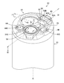
- FIG. 1 A perspective view showing the configuration of the tip surface of the insertion portion of the endoscope shown in FIG.
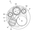
- Front view of the tip surface shown in FIG. Cross-sectional view of the tip portion 22 along the IV-IV line of FIG.
- FIG. 1 is an overall view of the endoscope 10 according to the embodiment of the present invention.
- the endoscope 10 does not include the elongated insertion portion 12 inserted into the subject, the operation portion 14 provided at the base end of the insertion portion 12, and the endoscope 10. It includes a universal cable 16 for connecting to system components such as the illustrated light source device, processor device, and air supply / water supply device.
- the insertion portion 12 has a tip, a base end, and a longitudinal axis A, and includes a soft portion 18, a curved portion 20, and a tip portion 22 in this order from the base end to the tip.
- the flexible portion 18 has flexibility and can be curved in any direction along the insertion path of the insertion portion 12.
- the curved portion 20 is curved in each of the vertical direction and the horizontal direction by operating the angle knobs 24 and 26 rotatably provided in the operating portion 14, and the direction in which the tip portion 22 faces can be changed in any direction.
- the tip portion 22 includes a tip portion main body 30 (see FIG. 2) arranged on the tip end side of the insertion portion 12, and the tip portion main body 30 has a tip surface 28.
- FIG. 2 is an enlarged perspective view of the tip portion 22, and FIG. 3 is a front view of the tip portion 22 viewed from the longitudinal axis A (see FIG. 1) direction. Further, FIG. 4 is a cross-sectional view of the tip portion 22 along the IV-IV line of FIG.
- the tip portion 22 is composed of a tip portion main body 30 made of a hard material such as metal and holding various parts arranged on the tip portion 22, and a tip portion made of an insulating resin material. It has a tip cover 32 that covers the tip surface 30A and the tip outer peripheral surface 30B of the main body 30. Note that, in FIG. 4, as parts held by the tip body 30 and the tip cover 32, a lens barrel 38 accommodating an observation window 34 and an optical system 36 constituting the observation unit, and air supply connected to the nozzle 40 are shown. The tip portion 42A of the water supply channel 42 is shown.
- the tip surface 28 is formed on the surface on the tip side of the tip cover 32.
- the tip surface 28 is formed based on a substantially circular flat surface perpendicular to the longitudinal axis A, and the observation window 34 and the two illumination windows 44 arranged around the observation window 34 are formed on the tip surface 28.
- the 46, the treatment tool outlet 48, and the nozzle 40 are arranged at predetermined positions.
- Reference numeral C shown in FIGS. 2 and 3 indicates the center of the tip surface 28.
- the observation window 34 is a component of the observation unit for acquiring an image of the observed portion, and a solid-state image sensor (not shown) or a solid-state imaging device (not shown) allows the subject light from the observed portion to be transmitted through the optical system 36 shown in FIG. Import into the image guide.
- the image taken by this observation unit is sent to the above-mentioned processor device as an observation image.
- the circular surface 34S of the observation window 34 is formed of, for example, a flat surface and is arranged perpendicular to the optical axis D of the observation unit.
- the center of the surface 34S is arranged at a position deviated from the center C of the tip surface 28 to the peripheral edge of the tip surface 28.
- the optical axis D is substantially parallel to the longitudinal axis A.
- the illumination windows 44 and 46 are components of the illumination unit for illuminating the observed portion, and irradiate the observed portion with the illumination light sent from the above-mentioned light source device.
- the circular surfaces 44S and 46S of the illumination windows 44 and 46 are formed of, for example, flat surfaces and are arranged perpendicular to the longitudinal axis A.
- the centers of the surfaces 44S and 46S are arranged at positions deviated from the center C of the tip surface 28 to the peripheral edge of the tip surface 28, and are arranged at positions facing each other with the surface 34S of the observation window 34 interposed therebetween. Will be done.
- the treatment tool outlet 48 is communicated with the treatment tool introduction port 50 of the operation unit 14 via a treatment tool insertion channel (not shown) inserted inside the insertion unit 12 (see FIG. 1). Therefore, the treatment tool introduced from the treatment tool introduction port 50 is led out from the treatment tool outlet 48 via the treatment tool insertion channel described above.
- a suction channel (not shown) is connected to the above-mentioned treatment tool insertion channel, and a suction operation from the treatment tool outlet 48 is performed via the suction channel by operating the suction button 54 of the operation unit 14 (see FIG. 1). Is done.
- the nozzle 40 is, for example, made of stainless steel and is a metal powder injection molded product (hereinafter, also referred to as a metal injection nozzle) manufactured by metal injection molding (MIM).
- Metal powder injection molding is a manufacturing method in which a metal powder and a binder are mixed and injection molded, the binder is degreased, and then sintered to produce a metal product.
- the nozzle 40 manufactured by this manufacturing method has a base end portion 40A and a tip end portion 40B, and the shape including the base end portion 40A and the tip end portion 40B is formed in an L shape. There is.
- the base end portion 40A constitutes a connection portion connected to the tip end portion 42A of the air supply / water supply channel 42, and is connected to the above-mentioned air supply / water supply device via the air supply / water supply channel 42.
- the conduit 41A of the base end portion 40A has a circular cross section perpendicular to the axis of the conduit 41A, and the circular center E is the tip surface with respect to the center C (see FIG. 3) of the tip surface 28. It is arranged at a position deviated from the peripheral edge of 28, and is arranged at a position close to the illumination window 46 among the illumination windows 44 and 46.
- the pipe line 41B of the tip portion 40B has a rectangular cross section perpendicular to the axis of the pipe line 41B, and a fluid injection port 52 opened toward the observation window 34 is formed at the tip of the pipe line 41B. There is.
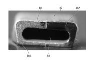
- FIG. 5 is an enlarged view of the fluid injection port 52 as viewed from the front.
- the fluid injection port 52 is configured as a rectangular opening similar to the cross-sectional shape of the pipeline 41B (see FIG. 4). Further, the nozzle 40 has a frame-shaped opening end surface 58 provided around the fluid injection port 52. As will be described later, of the opening end faces 58, the end face of the right half region of FIG. 5 close to the illumination window 46 (see FIG. 3) constitutes the scattering suppression portion 58A, and the left half region excluding the scattering suppression portion 58A.
- the end surface 58B is a satin-like surface that is the base material of the nozzle 40.
- the air supply / water supply device when the leak hole (not shown) formed in the air supply / water supply button 56 of the operation unit 14 (see FIG. 1) is closed with a finger, the air supply / water supply device can be used. Gas is injected from the fluid injection port 52 of the nozzle 40 toward the surface 34S of the observation window 34. Then, when the air supply / water supply button 56 is pressed with the finger that closes the leak hole, the cleaning liquid from the air supply / water supply device is ejected from the fluid injection port 52 toward the surface 34S of the observation window 34.
- the fluid injection port 52 As a procedure for cleaning the observation window 34, for example, after spraying a cleaning liquid from the fluid injection port 52 to remove deposits such as blood or body fluid adhering to the surface 34S of the observation window 34, the fluid injection port 52. A gas is injected to remove the cleaning liquid remaining on the surface 34S or the like of the observation window 34.
- each component observation window 34, nozzle 40, illumination window 44, 46 and treatment tool outlet 48 arranged on the tip surface 28 is arranged as the diameter of the tip portion 22 is reduced.
- the illumination light emitted from the illumination windows 44 and 46 is transmitted to the nozzle 40 as the observation field of view of the observation window 34 becomes wider or the illumination light distribution of the illumination windows 44 and 46 becomes wider. It becomes easy to be irradiated. Then, the reflected light of the illumination light reflected by the nozzle 40 is incident on the observation window 34, and flare occurs in the observation image, which tends to cause a problem that a clear observation image cannot be obtained.
- the nozzle 40 used in the endoscope 10 of the embodiment is a metal injection nozzle, and the outer surface of the nozzle 40 is formed of a satin-like surface. Therefore, when the illumination light emitted from the illumination windows 44 and 46 hits the nozzle 40, the reflected light is diffusely reflected by the outer surface (pear-skin texture) of the nozzle 40, so that the diffusely reflected reflected light is diffusely reflected by the observation window 34. The above problem becomes more prominent.
- the illumination light emitted from the illumination windows 44 and 46 on the outer surface of the nozzle 40 is emitted.
- the surface to be irradiated (hereinafter referred to as “irradiated surface”) is composed of a scattering suppression unit 58A having a mirror finish, and the reflected light of the illumination light reflected by the scattering suppression unit 58A is different from that of the observation window 34.
- the orientation of the surface (mirror surface) constituting the scattering suppression unit 58A is determined so as to reflect in the direction.
- one side of the opening end surface 58 which is a part of the outer surface of the nozzle 40, is closer to the illumination window 46.
- One half of the area (hereinafter referred to as “right half area”) is the area (irradiated surface) irradiated with the illumination light from the illumination window 46, and the other half area (hereinafter referred to as “right side area”).
- “Left half area” is an area that is not irradiated with the illumination light from the illumination windows 44 and 46.
- the base material (pear ground) of the nozzle 40 is left as it is for the end surface 58B of the left half region, and the end surface of the right half region to be the irradiated surface is a scattering suppression portion 58A composed of a mirror surface. .. Then, the open end surface 58 of the nozzle 40 has the tip end surface 58 so that the reflected light of the illumination light reflected by the scattering suppression unit 58A (mirror surface) is reflected toward the front side, which is the tip end side of the insertion unit 12 (see FIG. 1). It is composed of an inclined surface inclined with respect to the surface 28.
- the opening end surface 58 of the nozzle 40 will be described.
- the opening end surface 58 including the scattering suppression portion 58A is relative to the tip surface 28 when viewed from a direction orthogonal to the longitudinal axis A. It is configured as an acute-angled inclined surface inclined by ⁇ °.
- the reflected light of the illumination light reflected by the scattering suppression unit 58A is reflected toward the front side of the tip side of the insertion unit 12 (see FIG. 1) as shown by the arrow F direction, so that the observation window 34 It is prevented from being incident on.
- the irradiated surface of the nozzle 40 is composed of the scattering suppression unit 58A (mirror surface), and the reflected light of the illumination light irradiated to the irradiated surface is combined with the observation window 34.
- the reflected light does not enter the observation window 34 by reflecting the light in different directions, so that flare caused by the illumination light reflected by the nozzle 40 can be prevented and a good observation image can be obtained. ..
- the inclination angle ( ⁇ °) of the opening end surface 58 shown in FIG. 4 is preferably, for example, 50 ° or more and 60 ° or less.
- the temperature is set to 60 ° or less, the reflected light of the illumination light reflected by the scattering suppression unit 58A can be effectively reflected forward.
- the temperature is set to 50 ° or more, the fluid injected from the fluid injection port 52 can be effectively injected toward the observation window 34.
- the present invention is not limited to this, and the entire surface of the opening end face 58 (that is, the right half region and the left half region) is formed of a mirror surface. May be good.
- the scattering suppression portion 58A is preferably formed on the entire surface of the irradiated surface, but is not necessarily limited to this, and may be formed in at least a part of the irradiated surface.
- the configuration in which the scattering suppression portion 58A is formed in the entire right half region is illustrated, but the scattering suppression portion 58A may be formed in only a part of the right half region. Even in this case, a better observation image can be obtained as compared with the configuration without the scattering suppression unit 58A.
- the present invention is not limited to this.
- the present invention is also applied when a part or all of the other part or all of the opening end surface 58 is an irradiated surface, or when a part or all of the outer surface of the nozzle 40 other than the opening end surface 58 is an irradiated surface. Is possible.
- At least a part of the irradiated surface irradiated with the illumination light is a scattering suppression unit 58A composed of a mirror surface, and the scattering suppression unit 58A reflects the reflected light of the illumination light in a direction different from that of the observation window. By doing so, it is possible to prevent the occurrence of flare due to the illumination light reflected by the nozzle 40 and obtain a good observation image.
- the endoscope 10 provided with the two illumination windows 44 and 46 is illustrated, but the number of the illumination windows is not limited to two, and one or three or more illumination windows may be used. The present invention can be adopted even if the endoscope is provided.
- nozzle 40 a metal injection nozzle manufactured by metal powder injection molding is exemplified, but the present invention is not limited to this, and for example, the present invention is also applied to a nozzle manufactured by bending a pipe material. Can be adopted.
- the metal injection nozzle has an advantage that the burden on the subject can be reduced because the amount of protrusion from the tip surface 28 to the front can be suppressed as compared with the nozzle made of the pipe material.
- the outer surface of the metal injection nozzle has a satin-like surface, there is a problem that flare due to diffused reflection is likely to occur as described above. Therefore, by adopting the present invention for such a metal injection nozzle, in addition to the original effect that the burden on the subject can be reduced, the occurrence of flare due to the illumination light reflected by the nozzle 40 is prevented.
- the effect of the present invention that a good observation image can be obtained can be obtained.
- the flare of the present invention occurs even when the surface 34S of the observation window 34 is a flat surface, but it is more likely to occur when the surface 34A is a convex lens, so that the present invention is more effective as a measure against flare of the convex lens.
Landscapes
- Physics & Mathematics (AREA)
- Health & Medical Sciences (AREA)
- Life Sciences & Earth Sciences (AREA)
- Optics & Photonics (AREA)
- Surgery (AREA)
- General Physics & Mathematics (AREA)
- Astronomy & Astrophysics (AREA)
- Biomedical Technology (AREA)
- Animal Behavior & Ethology (AREA)
- Engineering & Computer Science (AREA)
- Pathology (AREA)
- Heart & Thoracic Surgery (AREA)
- Medical Informatics (AREA)
- Molecular Biology (AREA)
- Radiology & Medical Imaging (AREA)
- General Health & Medical Sciences (AREA)
- Public Health (AREA)
- Veterinary Medicine (AREA)
- Nuclear Medicine, Radiotherapy & Molecular Imaging (AREA)
- Biophysics (AREA)
- Endoscopes (AREA)
- Instruments For Viewing The Inside Of Hollow Bodies (AREA)
Abstract
Description
12 挿入部
14 操作部
16 ユニバーサルケーブル
18 軟性部
20 湾曲部
22 先端部
24 アングルノブ
26 アングルノブ
28 先端面
30 先端部本体
30A 先端面
30B 先端外周面
32 先端カバー
34 観察窓
34S 表面
36 光学系
38 鏡胴
40 ノズル
40A 基端部分
40B 先端部分
41A 管路
41B 管路
42 送気送水チャンネル
42A 先端部分
44 照明窓
44S 表面
46 照明窓
46S 表面
48 処置具導出口
50 処置具導入口
52 流体噴射口
54 吸引ボタン
56 送気送水ボタン
58 開口端面
58A 散乱抑制部
58B 端面
Claims (5)
- 体内に挿入される長尺状の挿入部を備えた内視鏡であって、
前記挿入部の先端側に配置された先端部本体を備え、前記先端部本体は先端面を有し、
前記先端面には、観察窓と、前記観察窓の周囲に配置される照明窓と、前記観察窓に向けて開口した流体噴射口を有するノズルとが設けられ、
前記ノズルは、前記照明窓から出射した照明光が照射される被照射面を有し、
前記被照射面の少なくとも一部は、鏡面により構成された散乱抑制部からなり、
前記散乱抑制部は、前記照明光を前記観察窓とは異なる方向に反射する、
内視鏡。 - 前記ノズルは、前記流体噴射口の周囲に設けられた開口端面を有し、
前記開口端面の少なくとも一部が前記散乱抑制部である、
請求項1に記載の内視鏡。 - 前記散乱抑制部は、前記先端面に対して傾斜した傾斜面により構成され、
前記散乱抑制部は、前記挿入部の先端側である前方に前記照明光を反射する、
請求項1又は2に記載の内視鏡。 - 前記照明窓は複数備えられ、
前記被照射面は、複数の前記照明窓のうち前記ノズルに最も近い位置の照明窓から出射された照明光によって照射される、
請求項1から3のいずれか1項に記載の内視鏡。 - 前記ノズルは金属粉末射出成形品であり、
前記ノズルの外表面の少なくとも一部に鏡面仕上げが施された前記散乱抑制部を有する、
請求項1から4のいずれか1項に記載の内視鏡。
Priority Applications (2)
| Application Number | Priority Date | Filing Date | Title |
|---|---|---|---|
| JP2022500364A JP7324928B2 (ja) | 2020-02-12 | 2021-02-05 | 内視鏡 |
| CN202180012871.3A CN115087388B (zh) | 2020-02-12 | 2021-02-05 | 内窥镜 |
Applications Claiming Priority (2)
| Application Number | Priority Date | Filing Date | Title |
|---|---|---|---|
| JP2020-021603 | 2020-02-12 | ||
| JP2020021603 | 2020-02-12 |
Publications (1)
| Publication Number | Publication Date |
|---|---|
| WO2021161902A1 true WO2021161902A1 (ja) | 2021-08-19 |
Family
ID=77291448
Family Applications (1)
| Application Number | Title | Priority Date | Filing Date |
|---|---|---|---|
| PCT/JP2021/004194 Ceased WO2021161902A1 (ja) | 2020-02-12 | 2021-02-05 | 内視鏡 |
Country Status (3)
| Country | Link |
|---|---|
| JP (1) | JP7324928B2 (ja) |
| CN (1) | CN115087388B (ja) |
| WO (1) | WO2021161902A1 (ja) |
Families Citing this family (1)
| Publication number | Priority date | Publication date | Assignee | Title |
|---|---|---|---|---|
| CN119033305B (zh) * | 2024-11-01 | 2025-03-07 | 湖南省华芯医疗器械有限公司 | 一种内窥镜的前端结构、插入部及内窥镜 |
Citations (8)
| Publication number | Priority date | Publication date | Assignee | Title |
|---|---|---|---|---|
| JPS5987422A (ja) * | 1982-11-11 | 1984-05-21 | Kobe Steel Ltd | 内視装置 |
| JPH09488A (ja) * | 1995-06-19 | 1997-01-07 | Olympus Optical Co Ltd | カバー式内視鏡 |
| JP2005168770A (ja) * | 2003-12-10 | 2005-06-30 | Olympus Corp | 内視鏡 |
| JP2006192200A (ja) * | 2005-01-17 | 2006-07-27 | Olympus Medical Systems Corp | 内視鏡用挿入部および内視鏡 |
| JP2012235970A (ja) * | 2011-05-13 | 2012-12-06 | Fujifilm Corp | 内視鏡 |
| WO2016181688A1 (ja) * | 2015-05-13 | 2016-11-17 | オリンパス株式会社 | 内視鏡 |
| JP2016202707A (ja) * | 2015-04-24 | 2016-12-08 | 富士フイルム株式会社 | 内視鏡 |
| WO2018179792A1 (ja) * | 2017-03-31 | 2018-10-04 | Hoya株式会社 | 内視鏡 |
Family Cites Families (3)
| Publication number | Priority date | Publication date | Assignee | Title |
|---|---|---|---|---|
| JP5384041B2 (ja) * | 2008-06-19 | 2014-01-08 | 富士フイルム株式会社 | 内視鏡 |
| JP5297901B2 (ja) * | 2009-06-04 | 2013-09-25 | Hoya株式会社 | 内視鏡挿入部の先端部構造 |
| JP6050221B2 (ja) * | 2013-12-20 | 2016-12-21 | 富士フイルム株式会社 | 内視鏡 |
-
2021
- 2021-02-05 CN CN202180012871.3A patent/CN115087388B/zh active Active
- 2021-02-05 JP JP2022500364A patent/JP7324928B2/ja active Active
- 2021-02-05 WO PCT/JP2021/004194 patent/WO2021161902A1/ja not_active Ceased
Patent Citations (8)
| Publication number | Priority date | Publication date | Assignee | Title |
|---|---|---|---|---|
| JPS5987422A (ja) * | 1982-11-11 | 1984-05-21 | Kobe Steel Ltd | 内視装置 |
| JPH09488A (ja) * | 1995-06-19 | 1997-01-07 | Olympus Optical Co Ltd | カバー式内視鏡 |
| JP2005168770A (ja) * | 2003-12-10 | 2005-06-30 | Olympus Corp | 内視鏡 |
| JP2006192200A (ja) * | 2005-01-17 | 2006-07-27 | Olympus Medical Systems Corp | 内視鏡用挿入部および内視鏡 |
| JP2012235970A (ja) * | 2011-05-13 | 2012-12-06 | Fujifilm Corp | 内視鏡 |
| JP2016202707A (ja) * | 2015-04-24 | 2016-12-08 | 富士フイルム株式会社 | 内視鏡 |
| WO2016181688A1 (ja) * | 2015-05-13 | 2016-11-17 | オリンパス株式会社 | 内視鏡 |
| WO2018179792A1 (ja) * | 2017-03-31 | 2018-10-04 | Hoya株式会社 | 内視鏡 |
Also Published As
| Publication number | Publication date |
|---|---|
| JP7324928B2 (ja) | 2023-08-10 |
| CN115087388A (zh) | 2022-09-20 |
| JPWO2021161902A1 (ja) | 2021-08-19 |
| CN115087388B (zh) | 2025-02-11 |
Similar Documents
| Publication | Publication Date | Title |
|---|---|---|
| CN102341028B (zh) | 内窥镜 | |
| US10779717B2 (en) | Endoscope | |
| CN101426414B (zh) | 内窥镜 | |
| JP6849567B2 (ja) | 内視鏡 | |
| CN102316783B (zh) | 内窥镜 | |
| JP6728480B2 (ja) | 内視鏡 | |
| CN102469924B (zh) | 内窥镜装置以及内窥镜 | |
| WO2012137737A1 (ja) | 内視鏡及び内視鏡用照明装置 | |
| WO2007029230A2 (en) | Disposable cap for endoscope | |
| US20190350449A1 (en) | Endoscope | |
| JP7324928B2 (ja) | 内視鏡 | |
| US11022740B2 (en) | Illumination unit for endoscope and endoscope | |
| CN102707427A (zh) | 内窥镜及其照明光学器件 | |
| US20210093176A1 (en) | Wafer lens array, layered lens array, image pickup unit, method for manufacturing layered lens array, and endoscope | |
| US10905314B2 (en) | Illumination device and endoscope | |
| JP3791910B2 (ja) | 内視鏡用フード | |
| JP4049859B2 (ja) | 内視鏡装置 | |
| JPWO2017179168A1 (ja) | 撮影装置 | |
| EP4574014A1 (en) | Endoscope with light guide and leds in distal tip | |
| US20200170494A1 (en) | Endoscope illumination unit and endoscope | |
| EP3695771A1 (en) | Illumination optical device and endoscope | |
| CN111031891B (zh) | 内窥镜 | |
| JPWO2017150154A1 (ja) | 内視鏡 | |
| JP2004267255A (ja) | 外套シース付内視鏡の先端部 | |
| JP2014239759A (ja) | 内視鏡、内視鏡システム |
Legal Events
| Date | Code | Title | Description |
|---|---|---|---|
| 121 | Ep: the epo has been informed by wipo that ep was designated in this application |
Ref document number: 21754222 Country of ref document: EP Kind code of ref document: A1 |
|
| ENP | Entry into the national phase |
Ref document number: 2022500364 Country of ref document: JP Kind code of ref document: A |
|
| NENP | Non-entry into the national phase |
Ref country code: DE |
|
| 122 | Ep: pct application non-entry in european phase |
Ref document number: 21754222 Country of ref document: EP Kind code of ref document: A1 |
|
| WWG | Wipo information: grant in national office |
Ref document number: 202180012871.3 Country of ref document: CN |