WO2021166633A1 - 画像露光装置、画像露光方法、及びプログラム - Google Patents
画像露光装置、画像露光方法、及びプログラム Download PDFInfo
- Publication number
- WO2021166633A1 WO2021166633A1 PCT/JP2021/003758 JP2021003758W WO2021166633A1 WO 2021166633 A1 WO2021166633 A1 WO 2021166633A1 JP 2021003758 W JP2021003758 W JP 2021003758W WO 2021166633 A1 WO2021166633 A1 WO 2021166633A1
- Authority
- WO
- WIPO (PCT)
- Prior art keywords
- image
- exposure
- divided
- display
- display device
- Prior art date
- Legal status (The legal status is an assumption and is not a legal conclusion. Google has not performed a legal analysis and makes no representation as to the accuracy of the status listed.)
- Ceased
Links
Images










Classifications
-
- G—PHYSICS
- G03—PHOTOGRAPHY; CINEMATOGRAPHY; ANALOGOUS TECHNIQUES USING WAVES OTHER THAN OPTICAL WAVES; ELECTROGRAPHY; HOLOGRAPHY
- G03B—APPARATUS OR ARRANGEMENTS FOR TAKING PHOTOGRAPHS OR FOR PROJECTING OR VIEWING THEM; APPARATUS OR ARRANGEMENTS EMPLOYING ANALOGOUS TECHNIQUES USING WAVES OTHER THAN OPTICAL WAVES; ACCESSORIES THEREFOR
- G03B27/00—Photographic printing apparatus
- G03B27/02—Exposure apparatus for contact printing
- G03B27/14—Details
- G03B27/16—Illumination arrangements, e.g. positioning of lamps, positioning of reflectors
-
- H—ELECTRICITY
- H04—ELECTRIC COMMUNICATION TECHNIQUE
- H04N—PICTORIAL COMMUNICATION, e.g. TELEVISION
- H04N23/00—Cameras or camera modules comprising electronic image sensors; Control thereof
- H04N23/70—Circuitry for compensating brightness variation in the scene
- H04N23/73—Circuitry for compensating brightness variation in the scene by influencing the exposure time
-
- G—PHYSICS
- G03—PHOTOGRAPHY; CINEMATOGRAPHY; ANALOGOUS TECHNIQUES USING WAVES OTHER THAN OPTICAL WAVES; ELECTROGRAPHY; HOLOGRAPHY
- G03B—APPARATUS OR ARRANGEMENTS FOR TAKING PHOTOGRAPHS OR FOR PROJECTING OR VIEWING THEM; APPARATUS OR ARRANGEMENTS EMPLOYING ANALOGOUS TECHNIQUES USING WAVES OTHER THAN OPTICAL WAVES; ACCESSORIES THEREFOR
- G03B27/00—Photographic printing apparatus
- G03B27/72—Controlling or varying light intensity, spectral composition, or exposure time in photographic printing apparatus
- G03B27/725—Optical projection devices wherein the contrast is controlled electrically (e.g. cathode ray tube masking)
-
- H—ELECTRICITY
- H04—ELECTRIC COMMUNICATION TECHNIQUE
- H04N—PICTORIAL COMMUNICATION, e.g. TELEVISION
- H04N23/00—Cameras or camera modules comprising electronic image sensors; Control thereof
- H04N23/10—Cameras or camera modules comprising electronic image sensors; Control thereof for generating image signals from different wavelengths
-
- H—ELECTRICITY
- H04—ELECTRIC COMMUNICATION TECHNIQUE
- H04N—PICTORIAL COMMUNICATION, e.g. TELEVISION
- H04N23/00—Cameras or camera modules comprising electronic image sensors; Control thereof
- H04N23/60—Control of cameras or camera modules
-
- H—ELECTRICITY
- H04—ELECTRIC COMMUNICATION TECHNIQUE
- H04N—PICTORIAL COMMUNICATION, e.g. TELEVISION
- H04N23/00—Cameras or camera modules comprising electronic image sensors; Control thereof
- H04N23/80—Camera processing pipelines; Components thereof
- H04N23/81—Camera processing pipelines; Components thereof for suppressing or minimising disturbance in the image signal generation
-
- H—ELECTRICITY
- H04—ELECTRIC COMMUNICATION TECHNIQUE
- H04N—PICTORIAL COMMUNICATION, e.g. TELEVISION
- H04N25/00—Circuitry of solid-state image sensors [SSIS]; Control thereof
- H04N25/50—Control of the SSIS exposure
- H04N25/57—Control of the dynamic range
- H04N25/58—Control of the dynamic range involving two or more exposures
-
- H—ELECTRICITY
- H10—SEMICONDUCTOR DEVICES; ELECTRIC SOLID-STATE DEVICES NOT OTHERWISE PROVIDED FOR
- H10W—GENERIC PACKAGES, INTERCONNECTIONS, CONNECTORS OR OTHER CONSTRUCTIONAL DETAILS OF DEVICES COVERED BY CLASS H10
- H10W90/00—Package configurations
Definitions
- the present disclosure relates to an image exposure apparatus, an image exposure method, and a program.
- the image exposure device that records a recorded image corresponding to the display image displayed by the image display device on the photosensitive material by exposing the photosensitive material such as a photosensitive recording medium with the light emitted from the image display device is known. Has been done.
- the gradation of the recorded image recorded on the photosensitive material is the gradation of the display image displayed on the image display device for exposure. It depends on the gradation. In other words, the gradation that can be expressed in the recorded image depends on the gradation of the image display device.
- the present disclosure has been made in view of such circumstances, and an image exposure capable of recording a recorded image having more gradations than the gradation of the display image displayed on the image display device on a photosensitive recording medium.
- Equipment, image exposure methods, and programs are provided.
- the image exposure device includes an image display device having a plurality of pixels, a photosensitive recording medium for recording a display image displayed on the image display device, and an image of the exposed surface of the photosensitive recording medium.
- a support portion that is supported so as to face the display device, a limiting member that is provided between the image display device and the support portion and that limits the angle of light emitted from the image display device to the photosensitive recording medium, and at least one.
- the image display device displays a display image for divided exposure, which comprises one processor and a memory for storing instructions that can be executed by the processor, and the processor has divided gradation values obtained by dividing the gradation values of the recorded image. Then, the display image for split exposure is used to sequentially expose the photosensitive recording medium a plurality of times, and the split exposure is performed so that the recorded image is recorded on the photosensitive recording medium.
- the sum of the division gradation values of the display image for division exposure used for each exposure in the division exposure is an image.
- the maximum number of gradations which is the maximum number of gradations that can be displayed on the display device, is exceeded.
- the sum of the divided gradation values is the same as the gradation value of the recorded image in the image exposure apparatus of the second aspect.
- the image exposure apparatus is the image exposure apparatus according to any one of the first to third aspects, and the number of exposures in the divided exposure is the number of gradations of the recorded image. It is an integer obtained by rounding up the first decimal place of the value divided by the maximum number of gradations.
- the exposure time of each time in the divided exposure is the same in the image exposure apparatus of any one aspect from the first aspect to the fourth aspect.
- each exposure time in the divided exposure is the largest on the photosensitive recording medium by the display image having the maximum number of gradations. It is the time obtained by dividing the exposure time at which a recorded image of a tun can be recorded by the number of exposures.
- the image exposure apparatus is the image exposure apparatus according to any one of the first to sixth aspects, wherein the processor is used for each exposure in the divided exposure for the divided exposure.
- the divided gradation value of the displayed image is specified, and the amount of light of the displayed image for divided exposure is controlled according to the specified divided gradation value.
- the image exposure apparatus includes the division gradation value of the display image for the division exposure used for the nth exposure in the division exposure and the n + 1th time in the image exposure apparatus according to the seventh aspect.
- the difference from the divided gradation value of the display image for divided exposure used for the exposure of is 1 or -1.
- the image exposure apparatus is an input having the same gradation value as the gradation value of the recorded image in the image exposure apparatus according to any one aspect from the first aspect to the eighth aspect.
- the image data of the image is input, and the processor generates a display image for split exposure from the input image.
- the image exposure apparatus is the image exposure apparatus according to any one aspect from the first aspect to the ninth aspect, and the processor uses the input image of the color represented by the input image data.
- a display image for split exposure of R component, a display image for split exposure of G component, and a display image for split exposure of B component are generated, and a display image for split exposure of R component and a split exposure of G component are generated.
- Each of the display image of the above and the display image for the divided exposure of the B component is sequentially displayed on the image display device in a predetermined order, and the divided exposure is performed for each of the RGB colors.
- the total amount of light for exposing the photosensitive recording medium is determined for each RGB color, and the processor uses the processor.
- the photosensitive recording medium is sequentially exposed by each of the display images for the divided exposure of the B component, and the divided exposure is performed for each of the RGB colors.
- the processor is a high-frequency component of the input image represented by the input image data.
- the image exposure apparatus is the image exposure apparatus according to any one aspect from the first aspect to the twelfth aspect, and the limiting member is an optical member of a diffusion optical system.
- an image display device having a plurality of pixels and a photosensitive recording medium for recording a display image displayed on the image display device are provided on an exposed surface of the photosensitive recording medium.
- an image display device having a plurality of pixels, a photosensitive recording medium for recording a display image displayed on the image display device, and an exposed surface of the photosensitive recording medium are imaged. It is provided with a support portion that is supported so as to face the display device, and a limiting member that is provided between the image display device and the support portion and limits the angle of light emitted from the image display device to the photosensitive recording medium.
- a display image for divided exposure having a divided gradation value obtained by dividing the gradation value of the recorded image is displayed on the image display device, and the display image for divided exposure is used as a photosensitive recording medium. This is for causing a computer to perform a process of performing a divided exposure in which a plurality of times of exposures are sequentially performed and a recorded image is recorded on a photosensitive recording medium.
- a recorded image of 256 gradations is recorded on a photosensitive recording medium with one exposure, the gradation value of the recorded image, the gradation value of the displayed image, and the amount of light applied to the photosensitive recording medium 14
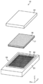
- FIG. 1 shows an exploded perspective view of an example of the image exposure apparatus of the present embodiment.
- FIG. 2 shows a cross-sectional view of an example of the image exposure apparatus of the present embodiment.
- the image exposure device 10 of the present embodiment includes an image display device 12, a support portion 21, and a louver film 16.
- the image display device 12 has a plurality of pixels 13.
- the support unit 21 supports a photosensitive recording medium 14 that records a recorded image according to the display image displayed by the image display device 12.
- the louver film 16 is provided between the image display device 12 and the support portion 21, and the protective layer 17 is provided on the support portion 21 side.
- the image display device 12 of the present embodiment includes a mobile terminal such as a smartphone and a tablet, a liquid crystal display device (LCD: Liquid Crystal Display), an organic EL display device (OLED: Organic Light Emitting Diode), and a brown tube display device (CRT: Cathode).
- LCD Liquid Crystal Display
- OLED Organic Light Emitting Diode
- CRT brown tube display device
- a Ray Tube a light emitting diode display device (LED: Light Emitting Diode), a plasma display device, or the like can be used.
- the image display device 12 includes a plurality of pixels 13 as a display unit 32 for displaying a display image.
- FIG. 2 shows one pixel 13 as an example of the display unit 32.
- the pixel 13 is the minimum unit of color information constituting the image display surface.
- the image display device 12 can display the displayed image.
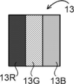
- FIG. 3 shows an example of the pixel 13 of the present embodiment.
- Pixel 13 includes three sub-pixels. Specifically, as shown in FIG. 3, the pixel 13 has a sub-pixel 13R corresponding to an R (Red) color, a sub-pixel 13G corresponding to a G (Green) color, and a B (Blue: blue). ) Sub-pixels 13B corresponding to colors are arranged in a row.
- a plurality of pixels 13 are arranged two-dimensionally on the pixel display surface of the image display device 12.
- the image display device 12 can display a color display image.
- the two-dimensional in the arrangement of the pixels 13 means a state extending in the XY directions in FIG.
- the pitch of the pixels 13 is preferably 150 ⁇ m or less, more preferably 125 ⁇ m or less, and even more preferably 85 ⁇ m or less.
- a glass window 26 for protecting the pixel 13 is provided on the surface side where light is emitted from the image display device 12.
- the thickness of the glass window 26 is preferably thin in order to shorten the distance from the pixel 13 to the photosensitive recording medium 14.
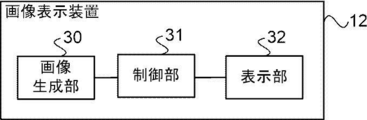
- FIG. 4 shows a block diagram showing an example of the functional configuration of the image display device 12 of the present embodiment.
- the image display device 12 of the present embodiment includes an image generation unit 30, a control unit 31, and a display unit 32.
- the image generation unit 30 of the present embodiment generates a display image in which the image quality of the input image is deteriorated by emphasizing the density difference of the high frequency component of the input image, and controls the image data representing the generated display image 31. Output to.
- the control unit 31 exposes the photosensitive recording medium 14 by displaying a display image corresponding to the input image represented by the image data input from the image generation unit 30 on the display unit 32, and responds to the input image represented by the image data. Control is performed so that the recorded image is recorded on the photosensitive recording medium 14.
- the gradation of the recorded image can be increased more than the gradation of the display image displayed on the display unit 32. Therefore, the control unit 31 controls the photosensitive recording medium 14 to record a recorded image having a larger number of gradations than the maximum number of gradations that can be displayed on the display unit 32.
- the number of gradations of the input image in this embodiment is the same as the number of gradations of the recorded image. Therefore, for example, in the image exposure apparatus 10 of the present embodiment, even when the display unit 32 is a liquid crystal display having 256 gradations (8 bits) and the gradation of the input image is 1024 gradations, it is photosensitive. A recorded image of 1024 gradations can be recorded on the recording medium 14.
- the specific configuration of the display unit 32 is not particularly limited as long as it includes the above-mentioned pixels 13 and irradiates light according to the display image represented by the pixels 13.
- a display unit 32 for example, a liquid crystal display to which a lamp such as a backlight irradiates light may be applied, or for example, a light emitting diode that irradiates light by itself is applied. You may.
- the control unit 31 of the present embodiment displays a display image for divided exposure having a divided gradation value obtained by dividing the gradation value of the recorded image on the display unit 32, and exposes the photosensitive recording medium 14 a plurality of times. I do.
- the control unit 31 controls the total amount of light emitted to the photosensitive recording medium 14 to be the amount of light according to the gradation of the input image by performing the exposure a plurality of times, thereby adjusting the gradation of the input image.
- control unit 31 of the present embodiment has a display image that is a color image, a display image for split exposure of the R (Rwd: red) component, a display image for split exposure of the G (Green) component, and B. Generates a display image for split exposure of the (Blue: blue) component. Further, the control unit 31 sequentially displays the display image for the divided exposure of the R component, the display image for the divided exposure of the G component, and the display image for the divided exposure of the B component on the display unit 32 in a predetermined order. Let me.
- the photosensitive recording medium 14 is displayed by sequentially displaying each of the display image for the divided exposure of the R component, the display image for the divided exposure of the G component, and the display image for the divided exposure of the B component on the display unit 32.
- the display image for the divided exposure of the R component, the display image for the divided exposure of the G component, and the display image for the divided exposure of the B component are sequentially exposed.
- this exposure method will be referred to as "RGB sequential exposure” for convenience.
- RGB sequential exposure the order of exposure is arbitrary and is not limited to the order of RGB.
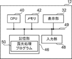
- the image display device 12 includes a computer including a CPU (Central Processing Unit) 40, a memory 42 as a temporary storage area, and a non-volatile storage unit 46.
- the image display device 12 includes the display unit 32 and the input unit 48.
- the CPU 40, the memory 42, the storage unit 46, the input unit 48, and the display unit 32 are connected via the bus 49.
- the storage unit 46 is realized by an HDD (Hard Disk Drive), an SSD (Solid State Drive), a flash memory, or the like.
- the exposure processing program 50 is stored in the storage unit 46 as a storage medium.
- the CPU 40 reads the exposure processing program 50 from the storage unit 46, expands the read exposure processing program 50 into the memory 42, and then executes the program.
- the CPU 40 functions as the image generation unit 30 and the control unit 31 shown in FIG.
- the image data of the input image is input to the input unit 48.
- the gradation of the input image of this embodiment is 1024 gradations.
- image data in which a gradation value (gradation value for 1024 gradations) is added to each pixel of an image of 256 gradations is used.
- the image data of the input image may be in the form of being input from the outside of the image display device 12 or the image exposure device 10, or the function of the image display device 12 or the image exposure device 10 itself to form or capture an image. In the case of, the image data formed or captured by itself may be input.
- the support portion 21 of the present embodiment supports the photosensitive recording medium 14 in a state of being arranged at a position facing the surface of the image display device 12 to be irradiated with light.
- the support unit 21 may directly or indirectly support the photosensitive recording medium 14, and its structure is not particularly limited as long as it can support the photosensitive recording medium 14.
- the photosensitive recording medium 14 of the present embodiment has an exposed surface 14A.
- the photosensitive recording medium 14 is not particularly limited as long as it can be exposed by the light emitted from the image display device 12 and can form a recorded image.
- a film pack 18 or the like to be attached to an instant camera for example, Instax (registered trademark) (trade name: Cheki) manufactured by FUJIFILM Corporation) can be used.
- the film pack 18 is formed by incorporating the photosensitive recording medium 14 into the case 20.
- a light-shielding sheet (not shown) is provided between the plurality of photosensitive recording media 14 provided in the case 20, and only the photosensitive recording medium 14 on the uppermost surface of the film pack 18 is provided by the light-shielding sheet. Is exposed.
- the photosensitive recording medium 14 and the light-shielding sheet are incorporated in the film.
- the material used for the photosensitive recording medium 14 include photographic photosensitive materials such as negative film, reversal film, photographic paper, monosheet, and beer apartment type instant photographic film.
- a plurality of photosensitive recording media 14 are housed in a box-shaped case 20 having a light-shielding property.
- the case 20 is provided with an exposure opening 22 that allows light emitted from the image display device 12 to pass through to expose the exposed surface of the photosensitive recording medium 14.
- a pressing member (not shown) is provided on the opposite side of the exposure opening 22, and the photosensitive recording medium 14 is pushed toward the exposure opening 22 by the pressing member. As a result, the photosensitive recording medium 14 is pressed around the exposure opening 22, the distance from the image display device 12 becomes short, and a good image can be recorded on the photosensitive recording medium 14.
- a resin member for a recording material used for various recording materials such as a photographic photosensitive material, a magnetic recording material, and an optical recording material can be used.
- the resin member for the recording material the container, the lid, and the accessory parts accompanying the container and the lid used for storing, packaging, coating, protecting, transporting, storing, and supporting the shape of the recording material, or the recording material is loaded. It refers to various members that exert their functions.
- the pod portion provided on the photosensitive recording medium bursts.
- a developing solution is contained in the pod, and when the pod bursts, the developing solution is spread inside the photosensitive recording medium 14. After 1 to several minutes have passed, the development process is sufficiently advanced and a recorded image is formed on the photosensitive recording medium 14.
- FIG. 6 is a schematic cross-sectional view of an example of the image exposure apparatus 10 of the present embodiment, and is a diagram for explaining the traveling direction of light from the pixel 13.
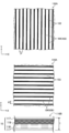
- FIG. 7 is a diagram showing a configuration of an example of the louver film 16 of the present embodiment.
- Reference numeral 16A is a plane 16A of the louver film 16
- reference numeral 16B is a side surface 16B of the louver film 16.
- the louver film 16 blocks light from the light transmitting portion 102 that transmits light in the first direction (X direction in the plane 16A in FIG. 7) on a surface parallel to the arrangement surface of the pixels 13 of the image display device 12.
- the light shielding portions 104 are arranged alternately.
- the light transmitting portion 102 and the light shielding portion 104 arranged in the first direction of the present embodiment are examples of the first light transmitting portion and the first light shielding portion of the present disclosure.
- the louver film 16 has a light transmitting portion 102 in a second direction (Y direction in the plane 16A in FIG. 7) on a plane perpendicular to the first direction and parallel to the pixel arrangement plane of the image display device.
- the light shielding portion 104 are arranged alternately.
- the light transmitting portion 102 and the light shielding portion 104 arranged in the second direction of the present embodiment are examples of the second light transmitting portion and the second light shielding portion of the present disclosure.
- the light transmitting portion 102 is arranged two-dimensionally, and the light shielding portion 104 is formed in a grid pattern.
- the angle of light emitted from the pixel 13 of the image display device 12 to the exposed surface 14A of the photosensitive recording medium 14 is limited.
- the louver film 16 of the present embodiment is an example of the limiting member of the present disclosure.
- the light emitted from the pixel 13 of the image display device 12 is emitted in all directions of 180 ° from the image display surface.
- the irradiated light passes through the glass window 26 provided in the image display device 12 and is incident on the louver film 16.
- light parallel to the straight line connecting the image display device 12 and the photosensitive recording medium 14 passes through the light transmitting portion 102 of the louver film 16.
- the light emitted obliquely with respect to the straight line connecting the image display device 12 and the photosensitive recording medium 14 is blocked by the light shielding portion 104 in the louver film 16.
- the light transmitting portion 102 only needs to allow light to pass through, and a glass material, transparent silicone rubber, or the like can be used. Further, the louver film 16 can be formed only by the light shielding portion 104 by making the portion of the light transmitting portion 102 hollow.
- the light shielding portion 104 may be a light absorbing member that absorbs light, or may be a light reflecting member that reflects light.
- a colored resin material can be used, and for example, black silicone rubber or the like can be used. Further, as a material that absorbs light, a neutral density filter (ND (Neutral Density) filter) can be used.
- ND Neutral Density
- the ND filter means a filter having a neutral optical density, and absorbs light evenly in the wavelength range used for exposure without affecting the wavelength (absorption rate of 50% or more and 99.999% or less; light transmittance). It is a filter that can be used at a rate of 0.001% or more and 50% or less).
- FIG. 8 shows the configuration of another example of the louver film 16.
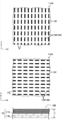
- the louver film 16 shown in FIG. 7 is formed of one layer, and the one layer includes a light transmitting portion 102 and a light shielding portion 104 in the first direction and the second direction. Are arranged alternately to form a two-dimensionally arranged louver film 16.
- the louver film 16 shown in FIG. 8 is composed of two layers, a first layer 118 and a second layer 119.
- Reference numeral 16B is a side surface of the louver film 16
- reference numeral 118A is a plane of the first layer 118
- reference numeral 119A is a plane of the second layer 119.
- the first layer 118 alternately arranges the light transmitting portion 102 and the light shielding portion 104 only in the first direction (the X direction in the plane 118A of FIG. 8). do.
- the light transmitting portion 102 and the light shielding portion 104 are alternately arranged only in the second direction (Y direction in the plane 119A in FIG.
- a protective layer 117 may be provided on the surface of the louver film 16 to prevent the louver film 16 from being damaged or damaged.
- the louver film 16 is opposite to the plane 118A of the first layer 118 on the side opposite to the side in contact with the second layer 119 and the side of the second layer 119 in contact with the first layer 118.
- a protective layer 117 may be provided on each of the side planes 119A.
- FIG. 9A when the protective layers 17 are provided on both sides of the louver film 16, defects in the louver film 16 or defects in the image generated based on the structure can be made inconspicuous.
- the protective layer 117 is not particularly limited as long as it is transparent and allows light to pass through.
- a plastic plate formed of an acrylic resin, polycarbonate, vinyl chloride resin, or the like can be used.
- At least one of the light shielding portions 104 in each column and each row may be composed of a plurality of light shielding members 106 having intervals.
- the first layer 118 is provided with each row of light shielding portions 104 arranged along the first direction at predetermined intervals along the second direction. It has a plurality of light shielding members 106.
- each row of the light shielding portions 104 arranged along the second direction is provided with a plurality of light shielding portions provided at predetermined intervals along the first direction. It has a member 106.
- the pitch P of the light shielding portion 104 of the louver film 16 is preferably 80 ⁇ m or less, more preferably 65 ⁇ m or less.
- the angle between the XY axis of the pixel, which is the reference of the arrangement of the pixels 13, and the XY axis of the louver, which is the reference of the arrangement of the light transmitting portion 102 and the light shielding portion 104 of the louver film 16, is different from each other to shield the light.
- the unit 104 may be arranged. Moire of the recorded image is suppressed by arranging the pixels 13 with different angles from the XY axes of the louvers and the XY axes of the louvers. This difference in angle is preferably 1 degree to 45 degrees, more preferably 5 degrees to 40 degrees, and even more preferably 10 degrees to 35 degrees.
- the thickness t of the louver film 16 is preferably 1.5 mm or more and 4.0 mm or less, more preferably 2.0 mm or more and 4.0 mm or less, and further preferably 2.5 mm or more and 4.0 mm or less.
- the thickness t of the louver film 16 is the thickness of one layer when it is formed of one layer as in the louver film 16 shown in FIG. 7.
- the film is formed of a plurality of layers such as two layers of the first layer 118 and the second layer 119 as in the louver film 16 shown in FIGS. 8 and 9, the total thickness of the plurality of layers is formed. Is the thickness t of the louver film 16.
- the protective layer 17 is provided on the support portion 21 side of the louver film 16.
- the protective layer 17 protects the louver film 16 in contact with the photosensitive recording medium 14 and the louver film 16 when exposure is performed.
- the protective layer 17 prevents the louver film 16 from being damaged or damaged by repeatedly exposing the display image displayed on the image display device 12 to the photosensitive recording medium 14.
- the protective layer 17 is not particularly limited as long as it is transparent and allows light to pass through.
- a plastic plate formed of an acrylic resin, polycarbonate, vinyl chloride resin, or the like can be used.
- the thickness of the protective layer 17 is preferably 0.1 ⁇ m or more and 500 ⁇ m or less.
- the thickness of the protective layer 17 is preferably 0.1 ⁇ m or more and 500 ⁇ m or less.
- the louver film 16 limits the angle of light emitted from the image display device 12, and light parallel to the straight line connecting the image display device 12 and the photosensitive recording medium 14 is emitted from the louver film 16. It passes through the light transmitting portion 102.
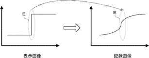
- the light emitted from the point light source 15 of the display unit 32 is diffused. Specifically, a light component having a constant angle is transmitted, that is, diffused according to the height H of the light shielding portion 104 and the width Q of the light transmitting portion 102. Due to the diffused light component, as shown in FIG. 11, in the recorded image recorded on the photosensitive recording medium 14, the density difference of the high frequency component (edge portion) E is reduced as compared with the displayed image. That is, in the recorded image, since the density difference becomes small, the edge portion tends to be difficult to see, and as a result, there is a high concern that the recorded image becomes a blurred image.
- the thickness t of the louver film 16 increases, the amount of light reaching the photosensitive recording medium 14 from the image display device 12 decreases, so that there is a problem that the exposure time becomes very long. Further, as in the example shown in FIGS. 8 and 9, when the louver film 16 is formed of a plurality of layers, light is diffused in the direction not shielded by the light shielding portion 104 in each layer. , The recorded image is likely to be blurred. Further, as the thickness of the protective layer 117 increases, the distance of the photosensitive recording medium 14 from the exposed surface 14A increases, and the angle of light is not limited in the protective layer 117, so that the recorded image tends to be blurred.
- the image generation unit 30 of the image display device 12 increases the high frequency component (edge portion) of the display image in advance in consideration of the fact that the density difference is smaller in the recorded image than in the display image.
- High-frequency component enhancement processing for (emphasis) is performed as image processing.
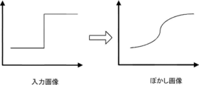
- the image generation unit 30 of the present embodiment performs an unsharp mask process as an example of the high frequency component enhancement process. Specifically, first, an unsharp mask is generated. To generate the unsharp mask, for example, a two-dimensional Gaussian distribution in which f (x, y) shown in the following equation (1) is used as the filter coefficient and the degree of distribution is set as the standard deviation ⁇ is applied.
- the standard deviation ⁇ in the above equation (1) is a Gaussian distribution, that is, a radius of blurring of a blurred image, and is expressed by the number of pixels (number of pixels) in the present embodiment.
- the image generation unit 30 generates a high frequency component image from the difference between the input image and the blurred image.
- the difference is particularly large in a region where the gradation difference is large.
- the image generation unit 30 adds a high frequency component image to the input image according to the weight W to generate a display image in which the high frequency component is emphasized. That is, the image quality of the displayed image is deteriorated as compared with the input image.
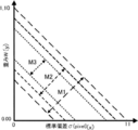
- the range of the unsharp mask to be applied is such that the standard deviation ⁇ is x and the weight W is set.
- the range M1 represented by the following formula (2) is preferable
- the range M2 represented by the following formula (3) is more preferable
- the range M3 is more preferable. -0.1 x x + 0.40 ⁇ y ⁇ -0.1 x x + 1.10 ... (2) -0.1 x x + 0.50 ⁇ y ⁇ -0.1 x x + 1.00 ... (3) -0.1 x x + 0.60 ⁇ y ⁇ -0.1 x x + 0.90 ... (4)
- an unsharp mask corresponding to the range obtained by multiplying the standard deviation ⁇ of the above equations (2) to (4) by the number obtained by dividing X by 325 can be applied. good.
- an unsharp mask corresponding to the range M1 to M3 represented by each of the following equations (5) to (7) may be applied.
- the display image for division exposure having the division gradation value is displayed a plurality of times on the display unit 32, and the photosensitive recording medium 14 is exposed a plurality of times.
- the divided exposure that enables the exposure of the recorded image having more gradations than the maximum number of gradations of the display unit 32 is performed. The number of exposures, the exposure time, and the divided gradation value in this divided exposure will be described.
- the number of exposures in the divided exposure (hereinafter, simply referred to as "the number of exposures") will be described.
- the number of exposures is determined according to the number of gradations of the recorded image and the maximum number of gradations of the display unit 32.
- the number of exposures when the number of gradations of the recorded image is X gradation and the maximum number of gradations of the display unit 32 is Y gradation is a value obtained by dividing X by Y (X / It is an integer with the first decimal place of Y) rounded up.
- the exposure time of each time in the divided exposure (hereinafter referred to as "divided exposure time") will be described.
- the divided exposure times are the same.
- the exposure time of each time may be different, it is preferable that the exposure time of each time is the same as in the present embodiment because a reciprocal irregularity may occur depending on the exposure time. Therefore, in the present embodiment, an exposure time (hereinafter, "" The value obtained by dividing the "appropriate exposure time" by the number of exposures is defined as the divided exposure time.
- the divided gradation value is a division of the gradation value of the recorded image, and in the present embodiment, the divided gradation value of the display image for the divided exposure is set for each exposure in the divided exposure.
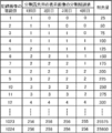
- FIG. 14 shows the gradation value of the recorded image, the divided gradation value of the display image for divided exposure used for each exposure in the divided exposure, and the total amount of light emitted to the photosensitive recording medium 14. An example of the correspondence with the amount of light) is shown.
- FIG. 14 shows an example in which the number of gradations of the recorded image is 1024 gradations, the maximum number of gradations of the display unit 32 is 256 gradations, the number of exposures is 4, and the divided exposure time is 25 msec.
- FIG. 15 shows an example in the case where the proper exposure time is 100 msec because the divided exposure is not performed.
- the total amount of light in FIG. 14 and the amount of light in FIG. 15 are determined on the photosensitive recording medium 14 in order to record a recorded image having a gradation value of "1" on the photosensitive recording medium 14 without performing divided exposure. It shows a relative value when the amount of light to be irradiated is set to "100".
- the photosensitive recording is performed by performing the exposure with the gradation value of the displayed image set to "1".
- the total amount of light emitted to the medium 14 is "100".
- the divided gradation value of the display image for the divided exposure when performing the divided exposure, when the gradation value of the recorded image is "1", in the first exposure, the divided gradation value of the display image for the divided exposure is "1". In the second exposure, the divided gradation value of the display image for divided exposure is set to "0", and in the third exposure, the divided gradation value of the displayed image for divided exposure is set to "0". do. Further, in the fourth exposure, it is shown that the division gradation value of the display image for division exposure is set to "0". By performing four exposures with these display images for divided exposure, the total amount of light emitted to the photosensitive recording medium 14 becomes "25". As described above, even if the gradation value of the recorded image is the same "1", the amount of light emitted to the photosensitive recording medium 14 differs depending on whether the divided exposure is performed or not. ..
- the amount of light "100" irradiated on the photosensitive recording medium 14 is the light irradiated on the photosensitive recording medium 14 in order to set the gradation value of the recorded image to "1".
- the gradation value of the recorded image is “4”.
- the divided gradation value of the display image for the divided exposure in the first exposure in the divided exposure, is set to "1", and in the second exposure, the displayed image for the divided exposure is displayed.
- the divided gradation value possessed is set to "1"
- the divided gradation value possessed by the display image for the divided exposure is set to "1".
- the division gradation value of the display image for division exposure is set to "1". As described above, even if the amount of light emitted to the photosensitive recording medium 14 is the same, the recorded image recorded on the photosensitive recording medium 14 is performed depending on whether the divided exposure is performed or not. The gradation value of is different.
- the amount of light (total amount of light) emitted to the photosensitive recording medium 14 can be finely set, so that recording can be performed.
- the image can be a multi-gradation image.
- the division gradation value of the display image for division exposure at each time of division exposure is not limited to the example shown in FIG.
- the divided gradation value of the displayed image for divided exposure is set to "4" in the first exposure, and the divided exposure is used in the second exposure.
- the divided gradation value of the displayed image is set to "3"
- the divided gradation value of the displayed image for divided exposure is set to "2" in the third exposure.
- the division gradation value of the display image for division exposure may be set to "1".
- This difference in gradation value may be different from that of the present embodiment, but the exposure intensity of the photosensitive recording medium 14 is too large or too small, and the sensitivity changes.
- the present embodiment is used.
- the divided exposure time, the number of exposures, and the correspondence relationship shown in FIG. 14 are stored in advance in the storage unit 46.
- FIG. 16 shows a flowchart of an example of the exposure process executed by the image display device 12 of the present embodiment.
- the exposure process shown in FIG. 16 is executed by the CPU 40 executing the exposure process program 50.
- step S100 shown in FIG. 16 the image generation unit 30 performs high-frequency component enhancement processing on the input image data to emphasize the density difference of the high-frequency component of the input image, and the high-frequency component. Generates a display image for split exposure with emphasized.
- the control unit 31 changes from the display image for the divided exposure to which the harmonic component enhancement processing is performed by the process of the step S100 to the display image for the divided exposure of the R component and the display for the divided exposure of the G component.
- An image and a display image for split exposure of the B component are generated.
- the control unit 31 of the present embodiment separates the color channels of the display image for split exposure and displays the display image for split exposure of each RGB component (single color image). ) was generated.
- the method by which the control unit 31 generates the display image for the divided exposure of each RGB component from the display image for the divided exposure is not limited to this method, and a known technique can be applied.
- the control unit 31 refers to the correspondence shown in FIG. 14 and specifies the divided gradation value for each divided exposure of the display image for the divided exposure of each RGB component. For example, when the gradation value of R of a pixel 13 of the display unit 32 is "7", the division gradation value of the pixel 13 in the first exposure is set for the display image for the division exposure of the R component. “2”, the divided gradation value in the second exposure is “2”, and the divided gradation value in the third exposure is “2”. Further, the divided gradation value in the fourth exposure is specified as "1".
- control unit 31 performs the divided exposure with the display image for the divided exposure of the B component according to the divided gradation value specified in the step S104.
- control unit 31 performs the divided exposure with the display image for the divided exposure of the G component according to the divided gradation value specified in the step S104.
- control unit 31 performs the divided exposure with the display image for the divided exposure of the R component according to the divided gradation value specified in the step S104.
- the divided exposure and the RGB sequential exposure are performed.
- the control unit 31 displays the display image for the divided exposure of the B component on the display unit 32 with the amount of light corresponding to the divided gradation value in the first exposure. Turn on (lights up).
- the control unit 31 changes the amount of light of the display image for the divided exposure of the B component from the amount of light corresponding to the divided gradation value in the first exposure to the divided gradation value in the second exposure. Switch to the amount of light according to.
- the control unit 31 switches the display image for split exposure to reduce the light intensity of the display image for split exposure of component B by 1.
- the amount of light corresponding to the divided gradation value in the second exposure is switched to the amount of light corresponding to the divided gradation value in the second exposure.
- the control unit 31 displays (lights) the display image for the divided exposure of the B component on the display unit 32 with the amount of light corresponding to the divided gradation value in the second exposure.
- the control unit 31 divides the amount of light of the display image for the divided exposure of the B component from the amount of light corresponding to the divided gradation value in the second exposure in the third exposure. Switch to the amount of light according to the gradation value.
- the control unit 31 displays the display image for the divided exposure without switching.
- the control unit 31 displays (lights) the display image for the divided exposure of the B component on the display unit 32 with the amount of light corresponding to the divided gradation value in the fourth exposure.
- the control unit 31 hides (turns off) the display image for the divided exposure of the B component.
- the control unit 31 sequentially turns on the sub-pixel 13B of the pixel 13 with the amount of light corresponding to the divided gradation value during the time T0 to T7, and records the photosensitivity by the display image for the divided exposure of the B component.
- the medium 14 is exposed four times.
- control unit 31 switches the image to be displayed on the display unit 32 from the display image for the divided exposure of the B component to the display image for the divided exposure of the G component during the period from the time T7 to the time T8, and when the time T8 is reached.
- the display image for the divided exposure of the G component is displayed (lit) on the display unit 32 with the amount of light corresponding to the divided gradation value in the first exposure.
- the display of the display image for the divided exposure of the G component is also controlled by the control unit 31 in the same manner as in the case of the B component described above.
- the control unit 31 sets the amount of light of the display image for the divided exposure of the G component from the amount of light corresponding to the divided gradation value in the first exposure to the second exposure.
- the amount of light is switched according to the divided gradation value in.
- the control unit 31 displays the display image for the divided exposure without switching.
- the control unit 31 displays (lights) the display image for the divided exposure of the G component on the display unit 32 with the amount of light corresponding to the divided gradation value in the second exposure.
- the control unit 31 divides the amount of light of the display image for the divided exposure of the G component from the amount of light corresponding to the divided gradation value in the second exposure in the third exposure. Switch to the amount of light according to the gradation value.
- the control unit 31 displays the display image for the divided exposure without switching.
- the control unit 31 displays (lights) the display image for the divided exposure of the G component on the display unit 32 with the amount of light corresponding to the divided gradation value in the fourth exposure.
- the control unit 31 hides (turns off) the display image for the divided exposure of the G component. Specifically, the control unit 31 sequentially lights the sub-pixel 13G of the pixel 13 with the amount of light corresponding to the divided gradation value during the time T8 to T15, and is photosensitive with the display image for the divided exposure of the G component.
- the recording medium 14 is exposed four times.
- control unit 31 switches the image to be displayed on the display unit 32 from the display image for the divided exposure of the G component to the display image for the divided exposure of the R component during the period from the time T15 to the time T16, and when the time T16 is reached.
- the display image for the divided exposure of the R component is displayed (lit) on the display unit 32 with the amount of light corresponding to the divided gradation value in the first exposure.
- the display of the display image for the divided exposure of the R component is also controlled by the control unit 31 in the same manner as in the case of the B component described above.
- the control unit 31 sets the amount of light of the display image for the divided exposure of the R component from the amount of light corresponding to the divided gradation value in the first exposure to the second exposure.
- the amount of light is switched according to the divided gradation value in.
- the control unit 31 displays the display image for the divided exposure without switching.
- the displayed image inside may be continuously displayed as the second display image as it is.
- the time T17 the time T18 because it is not necessary to provide a time for switching the display image for the divided exposure.
- the control unit 31 displays (lights) the display image for the divided exposure of the R component on the display unit 32 with the amount of light corresponding to the divided gradation value in the second exposure.
- the control unit 31 divides the amount of light of the display image for the divided exposure of the R component from the amount of light corresponding to the divided gradation value in the second exposure in the third exposure. Switch to the amount of light according to the gradation value.
- the control unit 31 displays the display image for the divided exposure without switching.
- the control unit 31 displays (lights) the display image for the divided exposure of the R component on the display unit 32 with the amount of light corresponding to the divided gradation value in the third exposure. Further, the control unit 31 sets the amount of light of the display image for the divided exposure of the R component from the amount of light corresponding to the divided gradation value in the third exposure to the divided floor in the fourth exposure during the period from time T21 to time T22. Switch to the amount of light according to the tuning. As described above, when the divided gradation value in the third exposure and the divided gradation value in the fourth exposure are the same, the control unit 31 displays the display image for the divided exposure without switching. The displayed image inside may be continuously displayed as the fourth display image as it is. In this case, since it is not necessary to provide a time for switching the display image for split exposure, the time is T21 and T22.
- the control unit 31 displays (lights) the display image for the divided exposure of the R component on the display unit 32 with the amount of light corresponding to the divided gradation value in the fourth exposure.
- the control unit 31 hides (turns off) the display image for the divided exposure of the R component. Specifically, the control unit 31 sequentially lights the sub-pixel 13R of the pixel 13 with the amount of light corresponding to the divided gradation value during the time T16 to T23, and is photosensitive with the display image for the divided exposure of the R component.
- the recording medium 14 is exposed four times.
- step S110 When the process of step S110 is completed, the main exposure process is completed.
- a recorded image having the same gradation value as the gradation value of the input image is recorded on the photosensitive recording medium 14 by the main exposure processing.
- the spectral characteristics of the image display device 12 and the photosensitive recording medium 14 are different, the color of the display image displayed on the image display device 12 and the recorded image recorded on the photosensitive recording medium 14, that is, the display image are exposed.
- the color of the recorded image may be different.
- an image optimized for the spectral characteristics of the human eye is usually used as a display image.
- the color of the recorded image recorded on the photosensitive recording medium 14 is different from the color of the display image.
- the photosensitive recording medium 14 is exposed to a display image having a strong green (G) color tint, a recorded image whose tint is biased toward the green (G) color can be obtained.
- the control unit 31 of the present embodiment displays a display image (exposure image) to be displayed on the image display device 12 when a recorded image having a bias toward the green (G) color is obtained as described above.
- the amount of green (G) light in the above is adjusted to be small.
- the assigned value of the gradation of each RGB color is set. There is a way to change it.
- the case where the displayed image has a strong green (G) color is the case where the exposure amount of green (G) is larger than the exposure amount of other colors in the exposure of the photosensitive recording medium 14.
- the control unit 31 sets, for example, the allocation value of the gradation in which the pixel value for green (G) is 200 in the image data representing the input image to 150. change.
- the control unit 31 adjusts the pixel value to "150".
- the gradation allocation value that is, the pixel value in the display image in this way, the exposure amount of green (G) is reduced, and a recorded image in which the tint is not biased toward the green (G) color can be obtained. can.
- the exposure amount is reduced, so that the tint is biased in the recorded image. Can be suppressed.
- the gradation from 0 to 255 is assigned to the gradation less than 0 to 255. That is, it means that the number of gradations in the recorded image is less than 255 gradations. Therefore, so-called gradation jumps, tone jumps, and the like may occur in the recorded image.
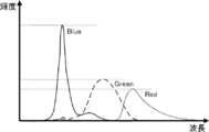
- FIG. 18 shows an example of the spectral characteristics of the arbitrary image display device 12.
- FIG. 19 shows an example of the spectral characteristics of the image display device 12 adjusted for optimizing the color tone of the recorded image recorded on the arbitrary photosensitive recording medium 14.
- the tint of the green (G) color is strong in the recorded image
- the case where the assigned value of the gradation of the green (G) color is adjusted is shown.
- the ratio of the brightness of the green (G) color to the blue (B) color is different, and in the adjusted image display device 12 shown in FIG. 19, blue (B) is used.
- the ratio of the brightness of the green (G) color to the color is small.
- 256 gradations are assigned to the maximum values of 0 to brightness for each of the red (R) color, the green (G) color, and the blue (B) color in the spectral characteristics shown in FIG.
- the maximum value of the brightness of the green (G) color is smaller than that before the adjustment, so that the gradation value that can be used is smaller than 255. ..
- the adjusted image display device 12 has 231 for the green (G) color. It becomes impossible to use the gradation of ⁇ 255.
- the exposure amount of each of RGB in the display image for exposing the photosensitive recording medium 14 is not optimized. Therefore, the number of gradations may decrease.
- the control unit 31 of the present embodiment suppresses the decrease in the number of gradations as described above by optimizing the exposure amount of each of RGB in the display image for exposing the photosensitive recording medium 14. .. Specifically, the control unit 31 optimizes the divided exposure time of each of RGB in the display image for divided exposure, and the display image for divided exposure of the R component, the display image for the divided exposure of the G component, and B. The exposure amount of each of RGB is optimized by sequentially displaying the display images for the divided exposure of the components on the image display device 12 in an arbitrary order and performing the divided exposure.
- FIG. 20 shows a flowchart showing an example of the flow of the exposure time optimization process for optimizing the exposure time.
- FIG. 21 shows an example of an evaluation system for spectral characteristics (luminance) used in optimizing the exposure time.
- a spectroradiometer "SR-3" manufactured by Topcon Techno House Co., Ltd. is used as the spectroradiometer 200, and the distance is 50 cm and the measurement angle is 2 degrees.
- the emission peak value of each RGB of the ideal image display device is measured.
- the ideal image display device is an image display device that displays a display image that matches the color of the recorded image recorded on the photosensitive recording medium 14. That is, the image display device 12 in a state in which the display image is optimized.
- an ideal image display device displays a display image for split exposure of the R component, that is, a red (R) color image having a pixel value of (255,0,0), and is shown in FIG.
- the emission peak value is measured by the evaluation system.
- an ideal image display device displays a display image for split exposure of the G component, that is, a green (G) color image having a pixel value of (0,255,0), and the evaluation system shown in FIG. 21.
- the emission peak value is measured by.
- an ideal image display device is displayed with a display image for split exposure of the B component, that is, a blue (B) color image having a pixel value of (0,0,255), and the evaluation shown in FIG. 21 is performed.
- the emission peak value is measured by the system.
- the maximum value (maximum amount of light) of the optimum brightness in each of red (R), green (G), and blue (B) can be obtained.
- step S202 shown in FIG. 20 the emission peak values of each of RGB of the current image display device 12 before being incorporated into the image exposure device 10 are measured.
- the emission peak value of each of RGB in the image display device 12 before the louver film 16 is provided is measured.
- the measurement method is the same as in step S100, on the image display device 12, an image of the R component (255,0,0), an image of the G component (0,255,0), and a B component (0,0,255). ) are sequentially displayed, and the emission peak value in each image is measured by the spectroradiometer 200.
- the maximum value (maximum amount of light) of the brightness in the current image exposure apparatus 10 in each of red (R), green (G), and blue (B) can be obtained.
- the exposure time of the display image for divided exposure of each RGB component is derived.
- the total amount of light that hits the photosensitive recording medium 14 in exposure is the amount obtained by multiplying each amount of light for each of RGB and the exposure time (light amount ⁇ exposure time).
- the amount of light exposed for 100 msec at the maximum value of the brightness in the ideal image display device measured in step S200 is defined as the total amount of light. That is, for each of RGB, the value obtained by multiplying the maximum value (maximum amount of light) of the brightness measured in step S200 by 100 msec is the total amount of light for each of RGB.
- the optimum exposure time of each of RGB is obtained by dividing each total light amount by the maximum value (maximum light amount) of the brightness in the image display device 12 measured in step S202 (total light amount ⁇ maximum light amount). Is obtained.
- the optimum exposure time of each of the RGB thus obtained is stored in advance in the storage unit 46 of the image display device 12.
- the exposure time optimized by the main exposure time optimization process is an appropriate exposure time. Therefore, the value obtained by dividing the exposure time optimized by the main exposure time optimization process by the number of exposures is the optimized divided exposure time.
- the method of optimizing the exposure time for each of RGB is not limited to the above-mentioned method.
- a white image 255, 255, 255
- the recorded image is optimized.
- the maximum value of the brightness of the display image (display image for divided exposure) for obtaining the optimum recorded image may be specified.
- the color adjustment of each gradation refers to the combination of the output values of each of R, G, and B with respect to the combination of the input values of R, G, and B, respectively, in a three-dimensional LUT (Look Up table). ) was used.
- the control unit 31 performs the divided exposure by RGB sequential exposure at the optimized exposure time, so that the number of gradations of the display image for the divided exposure can be reduced. It disappears and gradation skip is reduced. Therefore, in the image exposure apparatus 10 of the present embodiment, the display image for divided exposure becomes a smooth image. However, by reducing the gradation skip, the change in color shading is reduced, and as a result, the recorded image may become a blurred image. For example, as shown in FIG. 22, when the exposure time is optimized as compared with the case where gradation skipping occurs as described above, the recorded image has more gradations indicated by white circles in the graph. .. However, as shown in FIG. 22, in the recorded image in which the exposure time is optimized, the visibility of the edge portion is deteriorated and the image tends to be blurred.
- the image generation unit 30 of the image display device 12 increases the high frequency component (edge portion) of the display image in advance in consideration of the fact that the density difference is smaller in the recorded image than in the display image. Perform image processing to keep it (emphasized).
- the image generation unit 30 performs image processing for increasing (emphasizing) the high frequency component (edge portion) of the display image in advance in consideration of the fact that the image becomes blurred due to the optimization of the exposure time.
- FIG. 23 shows a flowchart of an example of the exposure process executed by the image display device 12 of the present embodiment.
- the exposure process shown in FIG. 23 is different from the exposure process of the first embodiment (see FIG. 16) in that the processes of steps S103A and S103B are further provided between steps S102 and S104.
- step S103A the control unit 31 acquires the optimum exposure time for each of RGB from the storage unit 46 as described above.
- step S103B the control unit 31 derives the divided exposure time for each of RGB. Specifically, the control unit 31 derives the divided exposure time for each of RGB by dividing the optimum exposure time of each of RGB acquired in step S103A by the number of exposures.
- the control unit 31 is used for the divided exposure of the R component according to the optimum exposure time, for example, as in the example shown in the time chart of FIG. 24.
- the display image, the display image for the divided exposure of the G component, and the display image for the divided exposure of the B component is displayed, and RGB sequential exposure and the divided exposure are performed.
- the image exposure apparatus 10 of the present embodiment in order to optimize the division exposure time of the display image for division exposure of each RGB component, as described above, the gradation of the display image for division exposure The skipping is reduced, and the display image for split exposure can be made a smooth image. Therefore, according to the image exposure apparatus 10 of the present embodiment, the color of the recorded image can be set to a desired color.
- the image exposure device 10 of each of the above embodiments is photosensitive with an image display device 12 having a plurality of pixels 13 and a photosensitive recording medium 14 for recording an image displayed on the image display device 12.
- a support portion 21 that supports the exposed surface 14A of the recording medium 14 facing the image display device 12 and an image display device 12 and the support portion 21 are provided between the support portion 21 and the image display device 12 to the photosensitive recording medium 14.
- the CPU 40 provided in the image display device 12 of the image exposure device 10 displays a display image for divided exposure on the display unit 32 of the image display device 12, which has a divided gradation value obtained by dividing the gradation value of the recorded image.
- the photosensitive recording medium 14 is subjected to a plurality of exposures in sequence according to the display image for the divided exposure, and the divided exposure is performed so that the recorded image is recorded on the photosensitive recording medium 14.
- the number of gradations of the recorded image recorded on the photosensitive recording medium 14 depends on the maximum number of gradations of the display unit 32 of the image display device 12. Therefore, when the divided exposure is not performed, the number of gradations of the recorded image is the maximum number of gradations of the display unit 32.
- the image exposure apparatus 10 of each of the above embodiments when the number of gradations of the desired recorded image is larger than the maximum number of gradations, for example, the number of gradations of the input image is larger than the maximum number of gradations.
- the divided exposure is performed by the display image for divided exposure having the divided gradation value obtained by dividing the gradation value of the recorded image by the number of exposures. As described above, in the image exposure apparatus 10 of each of the above embodiments, the amount of light emitted to the photosensitive recording medium 14 can be finely adjusted by increasing the number of exposures.
- a multi-gradation recording image is recorded as a photosensitive recording medium rather than the gradation of the display image (display image for split exposure) displayed on the image display device 12. It can be recorded in 14.
- the limitation on the number of gradations of the recorded image due to the maximum gradation of the display image (display image for split exposure) displayed on the image display device 12 is suppressed. be able to.
- the image display apparatus 12 having the display unit 32 having a relatively small maximum number of gradations can be used. Therefore, the image display device 12, and thus the image exposure device 10, can be easily configured.
- a mode in which RGB sequential exposure is performed has been described, but as shown in an example of the time chart of FIG. 25, a display image for split exposure of the R component and a display for the split exposure of the G component.
- the image and the display image for the divided exposure of the B component may be displayed on the display unit 32 at the same time. That is, it may be in the form of performing RGB batch exposure.
- the control unit 31 may acquire a predetermined number of gradations via, for example, the input unit 48 or the like. In this case, the control unit 31 derives the number of exposures and the divided exposure time in the divided exposure according to the acquired number of gradations.
- the image exposure apparatus 10 is used to record two types of recorded images, one is a recorded image having a larger number of gradations than the maximum number of gradations of the display unit 32, and the other is a recorded image having a lower number of gradations than the maximum number of gradations of the display unit 32. It may be an exposure apparatus capable of recording (exposing) an image on a photosensitive recording medium 14.
- the image exposure device 10 is such an exposure device, when a recorded image having a gradation number lower than the maximum gradation number of the display unit 32 is recorded on the photosensitive recording medium 14, division is performed by performing a plurality of exposures. Instead of the exposure, batch exposure may be performed with one exposure.
- each of the plurality of pixels 13 of the image display device 12 includes sub-pixels 13R, 13G, and 13B to cause the image display device 12 to display a color image.
- the configuration of the image display device 12 for displaying an image is not limited to this embodiment.
- the image display device 12 may be provided with a light source or a filter corresponding to each of the R component, the G component, and the B component.
- an unsharp mask process is described as a high-frequency component enhancement process performed by the image generation unit 30, but the present embodiment is not limited to this embodiment, and for example, a convolution process or the like is applied. May be good.
- the structure of the louver film 16 is not limited, and further, it is not limited as long as it is a limiting member capable of limiting the angle of the light emitted from the image display device 12.
- the light transmitting portion 102 and the light shielding portion 104 may be arranged in an aperiodic manner, or a capillary plate or the like having holes randomly formed may be used as the limiting member.
- each of the image generation unit 30 and the control unit 31 is a device different from the image display device 12. It may be configured. For example, when a CPU such as a smartphone executes the exposure processing program 50, it functions as an image generation unit 30 and a control unit 31 to perform image processing, and the image display device 12 uses the image data to which the image processing has been performed on the smartphone. A display image corresponding to the image data received from the display unit 32 may be displayed on the display unit 32. Further, the image generation unit 30 and the control unit 31 may be provided in different devices.
- various processors shown below are used.
- the various processors include a CPU, which is a general-purpose processor that executes software (program) and functions as various processing units, and after manufacturing an FPGA (Field-Programmable Gate Array) or the like.
- Dedicated processor with a circuit configuration designed exclusively for executing specific processing such as programmable logic device (PLD) and ASIC (Application Specific Integrated Circuit), which are processors whose circuit configuration can be changed. Includes electric circuits and the like.
- One processing unit may be composed of one of these various processors, or a combination of two or more processors of the same type or different types (for example, a combination of a plurality of FPGAs or a combination of a CPU and an FPGA). It may be composed of a combination). Further, a plurality of processing units may be configured by one processor.
- one processor is configured by a combination of one or more CPUs and software, as represented by a computer such as a client and a server.
- a processor functions as a plurality of processing units.
- SoC System On Chip
- a processor that realizes the functions of the entire system including a plurality of processing units with one IC (Integrated Circuit) chip is used.
- the various processing units are configured by using one or more of the above-mentioned various processors as a hardware structure.
- an electric circuit in which circuit elements such as semiconductor elements are combined can be used.
- the exposure processing program 50 is provided in a form recorded on a recording medium such as a CD-ROM (Compact Disc Read Only Memory), a DVD-ROM (Digital Versatile Disc Read Only Memory), and a USB (Universal Serial Bus) memory. May be good. Further, the exposure processing program 50 may be downloaded from an external device via a network.
- a recording medium such as a CD-ROM (Compact Disc Read Only Memory), a DVD-ROM (Digital Versatile Disc Read Only Memory), and a USB (Universal Serial Bus) memory. May be good.
- the exposure processing program 50 may be downloaded from an external device via a network.
- Image exposure device 12 Image display device 13 pixels, 13R, 13G, 13B Subpixel 14 Photosensitive recording medium, 14A Exposure surface 15 points Light source 16 Luber film, 16A Luber film flat surface, 16B Luber film side surface 17 Protective layer 18 film Pack 20 Case 21 Support 22 Exposure opening 26 Glass window 30 Image generator 31 Control 32 Display 34 Reception 40 CPU 42 Memory 46 Storage unit 48 Input unit 49 Bus 50 Exposure processing program 102 Light transmission unit 104 Light shielding unit 106 Light shielding member 117 Protective layer, 118A First layer plane 119 Second layer 119A First layer Plane of 2 layers 200 Spectroradiometer E High frequency component (edge) H Height M1 to M3 Range P Pitch of light shield Q Width t Louver film thickness T0 to T14, TX Time
Landscapes
- Engineering & Computer Science (AREA)
- Multimedia (AREA)
- Signal Processing (AREA)
- Physics & Mathematics (AREA)
- General Physics & Mathematics (AREA)
- Spectroscopy & Molecular Physics (AREA)
- Projection-Type Copiers In General (AREA)
- Exposure Or Original Feeding In Electrophotography (AREA)
- Color, Gradation (AREA)
Abstract
Description
(画像露光装置)
まず、本実施形態の画像露光装置の構成について説明する。図1には、本実施形態の画像露光装置の一例の分解斜視図を示す。また、図2には、本実施形態の画像露光装置の一例の断面図を示す。
本実施形態の画像表示装置12としては、スマートフォン及びタブレット等の携帯端末、液晶表示装置(LCD:Liquid Crystal Display)、有機EL表示装置(OLED:Organic Light Emitting Diode)、ブラウン管表示装置(CRT:Cathode Ray Tube)、発光ダイオード表示装置(LED:Light Emitting Diode)、及びプラズマ表示装置等を用いることができる。
本実施形態の支持部21は、画像表示装置12の光を照射する面に対向する位置に配置される状態に、感光性記録媒体14を支持する。なお、支持部21は、感光性記録媒体14を直接的に支持してもよいし、間接的に支持してもよく、感光性記録媒体14を支持することができればその構造は特に限定されない。
図2に示すように、本実施形態の感光性記録媒体14は露光面14Aを有する。感光性記録媒体14としては、画像表示装置12から照射された光により露光でき、記録画像を形成することができれば、特に限定されない。例えば、インスタントカメラ(例えば、富士フイルム(株)社製、Instax(登録商標)(商品名:チェキ))に装着するフィルムパック18等を用いることができる。
図6及び図7を参照して、本実施形態のルーバフィルム16の一例を説明する。図6は、本実施形態の画像露光装置10の一例の概略断面図であり、画素13からの光の進行方向を説明する図である。図7は、本実施形態のルーバフィルム16の一例の構成を示す図である。符号16Aはルーバフィルム16の平面16Aであり、符号16Bはルーバフィルム16の側面16Bである。ルーバフィルム16は、画像表示装置12の画素13の配列面と平行となる面上における第1の方向(図7の平面16AにおけるX方向)に、光を透過する光透過部102と光を遮断する光遮蔽部104とが交互に配置されている。本実施形態の第1の方向に配置されている光透過部102及び光遮蔽部104が、本開示の第1の光透過部及び第1の光遮蔽部の一例である。
保護層17は、図1、2、及び6に示すように、ルーバフィルム16の支持部21側に設けられている。保護層17は、露光を行う場合に、感光性記録媒体14とルーバフィルム16との接触においてルーバフィルム16を保護する。保護層17は、画像表示装置12に表示された表示画像を感光性記録媒体14に露光することを繰り返すことにより、ルーバフィルム16が傷ついたり破損したりすることを防止する。
次に、本実施形態の画像表示装置12における画像生成部30の作用を説明する。

なお、上記(1)式における標準偏差σは、ガウス分布、すなわちぼかし画像のぼかしの半径であり、本実施形態では画素数(ピクセル数)で表記する。
-0.1×x+0.40<y<-0.1×x+1.10 ・・・(2)
-0.1×x+0.50<y<-0.1×x+1.00 ・・・(3)
-0.1×x+0.60<y<-0.1×x+0.90 ・・・(4)
-0.1×x×(X÷325)+0.40<y<-0.1×x×(X÷325)+1.10 ・・・(5)
-0.1×x×(X÷325)+0.50<y<-0.1×x×(X÷325)+1.00 ・・・(6)
-0.1×x×(X÷325)+0.60<y<-0.1×x×(X÷325)+0.90 ・・・(7)
次に、本実施形態の画像表示装置12における制御部31の作用を説明する。
次に、本実施形態の画像表示装置12によって実行される露光処理について説明する。図16には、本実施形態の画像表示装置12によって実行される露光処理の一例のフローチャートが示されている。図16に示した露光処理は、CPU40が露光処理プログラム50を実行することにより実行される。
本実施形態では、感光性記録媒体14を露光するための分割露光用の表示画像におけるRGB各々の露光量の最適化の一例について説明する。なお、画像露光装置10の全体的な構成、おける支持部21、感光性記録媒体14、及びルーバフィルム16の構成は第1実施形態と同様なため説明を省略する。一方、本実施形態の画像露光装置10では、画像表示装置12の制御部31の作用か異なるため、制御部31の作用について説明する。
画像表示装置12から感光性記録媒体14に照射される光の分光特性と、感光性記録媒体14の分光感度、具体的には感光性記録媒体14の感材の分光感度(分光特性)とが異なる場合がある。画像表示装置12及び感光性記録媒体14各々の分光特性が異なると、画像表示装置12に表示される表示画像の色味と、感光性記録媒体14に記録される記録画像、即ち表示画像により露光された記録画像の色味とが異なる場合がある。例えば、画像表示装置12では、通常、人間の目の分光特性に最適化された画像が表示画像として用いられる。このように、人間の目の分光特性に最適化された表示画像により感光性記録媒体14を露光した場合、感光性記録媒体14に記録される記録画像の色味が表示画像の色味と異なることがある。例えば、表示画像が緑(G)色の色味が強い表示画像により感光性記録媒体14を露光した場合、緑(G)色に色味が偏った記録画像が得られる。
図20には、露光時間を最適化するための露光時間最適化処理の流れの一例を表したフローチャートが示されている。また、図21には、露光時間の最適化において用いる分光特性(輝度)の評価系の一例を示す。図21に示した評価系では、分光放射計200として、株式会社トプコンテクノハウス社製分光放射計「SR-3」を用い、距離を50cm、測定角を2度としている。
次に、本実施形態の画像表示装置12によって実行される露光処理について説明する。図23には、本実施形態の画像表示装置12によって実行される露光処理の一例のフローチャートが示されている。図23に示した露光処理は、ステップS102とステップS104との間に、ステップS103A及びS103Bの処理をさらに備える点で、第1実施形態の露光処理(図16参照)と異なっている。
本明細書に記載された全ての文献、特許出願、及び技術規格は、個々の文献、特許出願、及び技術規格が参照により取り込まれることが具体的かつ個々に記された場合と同程度に、本明細書中に参照により取り込まれる。
12 画像表示装置
13 画素、13R、13G、13B サブピクセル
14 感光性記録媒体、14A 露光面
15 点光源
16 ルーバフィルム、16A ルーバフィルムの平面、16B ルーバフィルムの側面
17 保護層
18 フィルムパック
20 ケース
21 支持部
22 露光開口
26 ガラス窓
30 画像生成部
31 制御部
32 表示部
34 受付部
40 CPU
42 メモリ
46 記憶部
48 入力部
49 バス
50 露光処理プログラム
102 光透過部
104 光遮蔽部
106 光遮蔽部材
117 保護層
118 第1の層、118A 第1の層の平面
119 第2の層、119A 第2の層の平面
200 分光放射計
E 高周波成分(エッジ部)
H 高さ
M1~M3 範囲
P 光遮蔽部のピッチ
Q 幅
t ルーバフィルムの厚み
T0~T14、TX 時刻
Claims (15)
- 複数の画素を有する画像表示装置と、
前記画像表示装置に表示される表示画像を記録する感光性記録媒体を、前記感光性記録媒体の露光面を前記画像表示装置に対向させて支持する支持部と、
前記画像表示装置と前記支持部との間に設けられ、かつ前記画像表示装置から前記感光性記録媒体へ照射される光の角度を制限する制限部材と、
少なくとも1つのプロセッサと、
前記プロセッサによって実行可能な命令を記憶するメモリと、を備え、
前記プロセッサは、
記録画像の階調値を分割した分割階調値を有する、分割露光用の表示画像を前記画像表示装置に表示させ、
前記分割露光用の表示画像により、前記感光性記録媒体の複数回の露光を順次行って、前記記録画像を前記感光性記録媒体に記録させる分割露光を行う
画像露光装置。 - 前記分割露光における各回の露光に用いられる前記分割露光用の表示画像の前記分割階調値の和は、
前記画像表示装置に表示が可能な階調数の最大値である最大階調数を越える
請求項1に記載の画像露光装置。 - 前記分割階調値の和は、前記記録画像の階調値と同一である
請求項2に記載の画像露光装置。 - 前記分割露光における露光回数は、前記記録画像の階調数を、最大階調数で割った値の小数点第一位を切り上げた整数である
請求項1から請求項3のいずれか1項に記載の画像露光装置。 - 前記分割露光における各回の露光時間は、同一である
請求項1から請求項4のいずれか1項に記載の画像露光装置。 - 前記分割露光における各回の露光時間は、最大階調数を有する表示画像により前記感光性記録媒体に前記最大階調数の記録画像が記録可能な露光時間を、露光回数で割った時間である
請求項5に記載の画像露光装置。 - 前記プロセッサは、
前記分割露光における各回の露光に用いられる前記分割露光用の表示画像が有する前記分割階調値を特定し、
特定した前記分割階調値に応じて前記分割露光用の表示画像の光量を制御する
請求項1から請求項6のいずれか1項に記載の画像露光装置。 - 前記分割露光におけるn回目の露光に用いられる前記分割露光用の表示画像の前記分割階調値と、n+1回目の露光に用いられる前記分割露光用の表示画像の前記分割階調値との差は1または-1である
請求項7に記載の画像露光装置。 - 前記記録画像の階調値と同一の階調値を有する入力画像の画像データが入力され、
前記プロセッサは、
前記入力画像から前記分割露光用の表示画像を生成する
請求項1から請求項8のいずれか1項に記載の画像露光装置。 - 前記プロセッサは、
入力された画像データが表すカラーの入力画像からR成分の分割露光用の表示画像、G成分の分割露光用の表示画像、及びB成分の分割露光用の表示画像を生成し、
前記R成分の分割露光用の表示画像、前記G成分の分割露光用の表示画像、及び前記B成分の分割露光用の表示画像の各々を、前記画像表示装置に予め定められた順番で順次表示させて、RGBの色毎に前記分割露光を行う
請求項1から請求項9のいずれか1項に記載の画像露光装置。 - RGBの色毎に、前記感光性記録媒体を露光させるための総光量が定められており、
前記プロセッサは、前記画像表示装置において表示されるRGB各々の色の光の最大光量と、前記総光量とに応じた露光時間で、前記R成分の分割露光用の表示画像、前記G成分の分割露光用の表示画像、及び前記B成分の分割露光用の表示画像各々により前記感光性記録媒体を順次露光させて、RGBの色毎に前記分割露光を行う
請求項10に記載の画像露光装置。 - 前記プロセッサは、
入力された画像データが表す入力画像の高周波成分の濃度差を強調させることにより、前記入力画像の画質を劣化させた前記分割露光用の表示画像を生成する
請求項1から請求項11のいずれか1項に記載の画像露光装置。 - 前記制限部材は、拡散光学系の光学部材である
請求項1から請求項12のいずれか1項に記載の画像露光装置。 - 複数の画素を有する画像表示装置と、前記画像表示装置に表示される表示画像を記録する感光性記録媒体を、前記感光性記録媒体の露光面を前記画像表示装置に対向させて支持する支持部と、前記画像表示装置と前記支持部との間に設けられ、かつ前記画像表示装置から前記感光性記録媒体へ照射される光の角度を制限する制限部材と、を備えた画像露光装置における画像露光方法であって、
記録画像の階調値を分割した分割階調値を有する、分割露光用の表示画像を前記画像表示装置に表示させ、
前記分割露光用の表示画像により、前記感光性記録媒体の複数回の露光を順次行って、前記記録画像を前記感光性記録媒体に記録させる分割露光を行う
処理をコンピュータが実行する画像露光方法。 - 複数の画素を有する画像表示装置と、前記画像表示装置に表示される表示画像を記録する感光性記録媒体を、前記感光性記録媒体の露光面を前記画像表示装置に対向させて支持する支持部と、前記画像表示装置と前記支持部との間に設けられ、かつ前記画像表示装置から前記感光性記録媒体へ照射される光の角度を制限する制限部材と、を備えた画像露光装置に対して、
記録画像の階調値を分割した分割階調値を有する、分割露光用の表示画像を前記画像表示装置に表示させ、
前記分割露光用の表示画像により、前記感光性記録媒体の複数回の露光を順次行って、前記記録画像を前記感光性記録媒体に記録させる分割露光を行う
処理をコンピュータに実行させるためのプログラム。
Priority Applications (4)
| Application Number | Priority Date | Filing Date | Title |
|---|---|---|---|
| CN202180012952.3A CN115053179B (zh) | 2020-02-18 | 2021-02-02 | 图像曝光装置、图像曝光方法及记录介质 |
| EP21756876.5A EP4109176A4 (en) | 2020-02-18 | 2021-02-02 | IMAGE EXPOSURE DEVICE, IMAGE EXPOSURE METHOD AND PROGRAM |
| JP2022501761A JP7378570B2 (ja) | 2020-02-18 | 2021-02-02 | 画像露光装置、画像露光方法、及びプログラム |
| US17/878,848 US12047684B2 (en) | 2020-02-18 | 2022-08-01 | Image exposure device, image exposure method, and program |
Applications Claiming Priority (2)
| Application Number | Priority Date | Filing Date | Title |
|---|---|---|---|
| JP2020025671 | 2020-02-18 | ||
| JP2020-025671 | 2020-02-18 |
Related Child Applications (1)
| Application Number | Title | Priority Date | Filing Date |
|---|---|---|---|
| US17/878,848 Continuation US12047684B2 (en) | 2020-02-18 | 2022-08-01 | Image exposure device, image exposure method, and program |
Publications (1)
| Publication Number | Publication Date |
|---|---|
| WO2021166633A1 true WO2021166633A1 (ja) | 2021-08-26 |
Family
ID=77391374
Family Applications (1)
| Application Number | Title | Priority Date | Filing Date |
|---|---|---|---|
| PCT/JP2021/003758 Ceased WO2021166633A1 (ja) | 2020-02-18 | 2021-02-02 | 画像露光装置、画像露光方法、及びプログラム |
Country Status (5)
| Country | Link |
|---|---|
| US (1) | US12047684B2 (ja) |
| EP (1) | EP4109176A4 (ja) |
| JP (1) | JP7378570B2 (ja) |
| CN (1) | CN115053179B (ja) |
| WO (1) | WO2021166633A1 (ja) |
Families Citing this family (2)
| Publication number | Priority date | Publication date | Assignee | Title |
|---|---|---|---|---|
| WO2021060555A1 (ja) * | 2019-09-27 | 2021-04-01 | 富士フイルム株式会社 | 画像露光装置、画像露光方法、及びプログラム |
| WO2021153356A1 (ja) * | 2020-01-28 | 2021-08-05 | 富士フイルム株式会社 | 情報処理方法 |
Citations (6)
| Publication number | Priority date | Publication date | Assignee | Title |
|---|---|---|---|---|
| JPH06222467A (ja) * | 1993-01-22 | 1994-08-12 | Citizen Watch Co Ltd | 画像形成方法 |
| JP2001045342A (ja) | 1999-08-02 | 2001-02-16 | Nippon Polaroid Kk | 画像表示機能を備える露光装置、露光機能を備える電子カメラ、情報端末および携帯通信装置 |
| JP2001092016A (ja) * | 1999-07-21 | 2001-04-06 | Mitsubishi Electric Corp | プリント機能付きディスプレイ装置 |
| JP2002019187A (ja) * | 2000-07-11 | 2002-01-23 | Fuji Photo Film Co Ltd | 画像形成方法及び装置 |
| JP2006246080A (ja) * | 2005-03-03 | 2006-09-14 | Sony Corp | 画像処理方法、画像処理装置、プログラム、および撮影装置 |
| JP2020025671A (ja) | 2018-08-10 | 2020-02-20 | 株式会社三共 | 遊技機 |
Family Cites Families (9)
| Publication number | Priority date | Publication date | Assignee | Title |
|---|---|---|---|---|
| US6034710A (en) * | 1994-11-16 | 2000-03-07 | Konica Corporation | Image forming method for silver halide photographic material |
| JP3781050B1 (ja) * | 2005-02-22 | 2006-05-31 | 三菱電機株式会社 | 画像処理装置、画像処理方法、および画像表示装置 |
| WO2007113941A1 (ja) | 2006-04-05 | 2007-10-11 | Sharp Kabushiki Kaisha | 表示パネル用の基板、この基板を備える表示パネル、表示パネル用の基板の製造方法および表示パネルの製造方法 |
| US9126396B2 (en) * | 2013-11-21 | 2015-09-08 | Pacific Opal LLC | Instant film printer for light emitting display screen incorporating optical collimation layer |
| JP2017049336A (ja) * | 2015-08-31 | 2017-03-09 | 株式会社ジャパンディスプレイ | 表示装置 |
| CN105578076A (zh) * | 2015-12-18 | 2016-05-11 | 广东欧珀移动通信有限公司 | 成像方法、成像装置及电子装置 |
| JP2018194592A (ja) * | 2017-05-12 | 2018-12-06 | 株式会社ジャパンディスプレイ | 表示装置 |
| WO2019187751A1 (ja) * | 2018-03-30 | 2019-10-03 | 富士フイルム株式会社 | 画像露光装置、画像露光方法、及びプログラム |
| CN108989700B (zh) * | 2018-08-13 | 2020-05-15 | Oppo广东移动通信有限公司 | 成像控制方法、装置、电子设备以及计算机可读存储介质 |
-
2021
- 2021-02-02 WO PCT/JP2021/003758 patent/WO2021166633A1/ja not_active Ceased
- 2021-02-02 EP EP21756876.5A patent/EP4109176A4/en active Pending
- 2021-02-02 CN CN202180012952.3A patent/CN115053179B/zh active Active
- 2021-02-02 JP JP2022501761A patent/JP7378570B2/ja active Active
-
2022
- 2022-08-01 US US17/878,848 patent/US12047684B2/en active Active
Patent Citations (6)
| Publication number | Priority date | Publication date | Assignee | Title |
|---|---|---|---|---|
| JPH06222467A (ja) * | 1993-01-22 | 1994-08-12 | Citizen Watch Co Ltd | 画像形成方法 |
| JP2001092016A (ja) * | 1999-07-21 | 2001-04-06 | Mitsubishi Electric Corp | プリント機能付きディスプレイ装置 |
| JP2001045342A (ja) | 1999-08-02 | 2001-02-16 | Nippon Polaroid Kk | 画像表示機能を備える露光装置、露光機能を備える電子カメラ、情報端末および携帯通信装置 |
| JP2002019187A (ja) * | 2000-07-11 | 2002-01-23 | Fuji Photo Film Co Ltd | 画像形成方法及び装置 |
| JP2006246080A (ja) * | 2005-03-03 | 2006-09-14 | Sony Corp | 画像処理方法、画像処理装置、プログラム、および撮影装置 |
| JP2020025671A (ja) | 2018-08-10 | 2020-02-20 | 株式会社三共 | 遊技機 |
Also Published As
| Publication number | Publication date |
|---|---|
| JP7378570B2 (ja) | 2023-11-13 |
| US20220368821A1 (en) | 2022-11-17 |
| JPWO2021166633A1 (ja) | 2021-08-26 |
| EP4109176A1 (en) | 2022-12-28 |
| CN115053179A (zh) | 2022-09-13 |
| CN115053179B (zh) | 2025-01-07 |
| EP4109176A4 (en) | 2023-08-02 |
| US12047684B2 (en) | 2024-07-23 |
Similar Documents
| Publication | Publication Date | Title |
|---|---|---|
| JP7047069B2 (ja) | 画像露光装置、画像露光方法、及びプログラム | |
| ES2311061T3 (es) | Procedimiento y sistema para proporcionar informaciones formateadas a medios de tratamiento de imagenes. | |
| Cooper et al. | Analysis and extensions of the Frankle-McCann Retinex algorithm | |
| JP2019066858A (ja) | 各種ディスプレイにおけるグローバル光補償 | |
| KR20160040596A (ko) | 다이내믹 컬러 쉐이딩 보정 | |
| US12047684B2 (en) | Image exposure device, image exposure method, and program | |
| CN114281274B (zh) | 光亮度均匀性的调节方法、打印方法、打印系统及设备 | |
| US12197116B2 (en) | Image exposure device, image exposure method, and program | |
| US20200019041A1 (en) | Lighting assembly for producing realistic photo images | |
| CN114730548B (zh) | 拼接屏白平衡调整的方法和装置、电子设备、介质 | |
| CN114007055A (zh) | 图像传感器镜头阴影校正方法及装置 | |
| JP6119155B2 (ja) | 調光制御装置、画像表示装置、調光制御方法及びプログラム | |
| US20230185179A1 (en) | Image exposure device, image exposure method, and program | |
| JP7321296B2 (ja) | 情報処理方法 | |
| Emmel | Novel backlighting techniques for high dynamic range displays | |
| Salazar | Analysis and test of image acquisition methods for cinematography | |
| CN120201314A (zh) | 图像处理方法及装置、设备、程序产品、存储介质 | |
| Zhang | Appearance-based image splitting for HDR display systems | |
| JP2003281510A (ja) | 画像読み取り装置 |
Legal Events
| Date | Code | Title | Description |
|---|---|---|---|
| 121 | Ep: the epo has been informed by wipo that ep was designated in this application |
Ref document number: 21756876 Country of ref document: EP Kind code of ref document: A1 |
|
| ENP | Entry into the national phase |
Ref document number: 2022501761 Country of ref document: JP Kind code of ref document: A |
|
| NENP | Non-entry into the national phase |
Ref country code: DE |
|
| ENP | Entry into the national phase |
Ref document number: 2021756876 Country of ref document: EP Effective date: 20220919 |
|
| WWG | Wipo information: grant in national office |
Ref document number: 202180012952.3 Country of ref document: CN |