WO2021167073A1 - 誘電体導波線路 - Google Patents
誘電体導波線路 Download PDFInfo
- Publication number
- WO2021167073A1 WO2021167073A1 PCT/JP2021/006402 JP2021006402W WO2021167073A1 WO 2021167073 A1 WO2021167073 A1 WO 2021167073A1 JP 2021006402 W JP2021006402 W JP 2021006402W WO 2021167073 A1 WO2021167073 A1 WO 2021167073A1
- Authority
- WO
- WIPO (PCT)
- Prior art keywords
- dielectric
- ptfe
- layer
- relative permittivity
- less
- Prior art date
- Legal status (The legal status is an assumption and is not a legal conclusion. Google has not performed a legal analysis and makes no representation as to the accuracy of the status listed.)
- Ceased
Links
Images


Classifications
-
- H—ELECTRICITY
- H01—ELECTRIC ELEMENTS
- H01P—WAVEGUIDES; RESONATORS, LINES, OR OTHER DEVICES OF THE WAVEGUIDE TYPE
- H01P3/00—Waveguides; Transmission lines of the waveguide type
- H01P3/16—Dielectric waveguides, i.e. without a longitudinal conductor
-
- C—CHEMISTRY; METALLURGY
- C08—ORGANIC MACROMOLECULAR COMPOUNDS; THEIR PREPARATION OR CHEMICAL WORKING-UP; COMPOSITIONS BASED THEREON
- C08F—MACROMOLECULAR COMPOUNDS OBTAINED BY REACTIONS ONLY INVOLVING CARBON-TO-CARBON UNSATURATED BONDS
- C08F14/00—Homopolymers and copolymers of compounds having one or more unsaturated aliphatic radicals, each having only one carbon-to-carbon double bond, and at least one being terminated by a halogen
- C08F14/18—Monomers containing fluorine
- C08F14/26—Tetrafluoroethene
-
- H—ELECTRICITY
- H01—ELECTRIC ELEMENTS
- H01P—WAVEGUIDES; RESONATORS, LINES, OR OTHER DEVICES OF THE WAVEGUIDE TYPE
- H01P1/00—Auxiliary devices
- H01P1/20—Frequency-selective devices, e.g. filters
- H01P1/2002—Dielectric waveguide filters
-
- H—ELECTRICITY
- H01—ELECTRIC ELEMENTS
- H01P—WAVEGUIDES; RESONATORS, LINES, OR OTHER DEVICES OF THE WAVEGUIDE TYPE
- H01P11/00—Apparatus or processes specially adapted for manufacturing waveguides or resonators, lines, or other devices of the waveguide type
- H01P11/001—Manufacturing waveguides or transmission lines of the waveguide type
-
- H—ELECTRICITY
- H01—ELECTRIC ELEMENTS
- H01P—WAVEGUIDES; RESONATORS, LINES, OR OTHER DEVICES OF THE WAVEGUIDE TYPE
- H01P11/00—Apparatus or processes specially adapted for manufacturing waveguides or resonators, lines, or other devices of the waveguide type
- H01P11/001—Manufacturing waveguides or transmission lines of the waveguide type
- H01P11/006—Manufacturing dielectric waveguides
-
- H—ELECTRICITY
- H01—ELECTRIC ELEMENTS
- H01P—WAVEGUIDES; RESONATORS, LINES, OR OTHER DEVICES OF THE WAVEGUIDE TYPE
- H01P3/00—Waveguides; Transmission lines of the waveguide type
- H01P3/12—Hollow waveguides
Definitions
- the present disclosure relates to a dielectric waveguide.
- Patent Document 1 describes a dielectric waveguide including a polytetrafluoroethylene molded product having a dielectric constant, a dielectric loss tangent and a hardness within a specific range.
- An object of the present disclosure is to provide a dielectric waveguide capable of reducing the penetration of electromagnetic waves.
- the present disclosure is a dielectric waveguide including a central dielectric A1, a dielectric layer A2 provided around the central dielectric A1, and a dielectric layer A3 provided around the dielectric layer A2.
- the central dielectric A1 contains polytetrafluoroethylene, and the specific dielectric constants of the central dielectric A1, the dielectric layer A2 and the dielectric layer A3 at 25 ° C. and 6 GHz are expressed as ⁇ A1 , ⁇ A2 and ⁇ A3 , respectively.
- ⁇ A1 is 2.20 or less
- ⁇ A2 is 1.90 or less
- ⁇ A3 is 1.55 or less
- tan ⁇ A1 is 2.20 ⁇ 10 -4 or less. It is preferable that tan ⁇ A2 is 1.20 ⁇ 10 -4 or less, and tan ⁇ A3 is 1.00 ⁇ 10 -4 or less.
- the dielectric layers A2 and A3 are at least one selected from the group consisting of polytetrafluoroethylene, tetrafluoroethylene / hexafluoropropylene copolymer, tetrafluoroethylene / perfluoro (alkyl vinyl ether) copolymer and polyolefin. It is preferable to contain the resin A.
- the present disclosure is a dielectric waveguide comprising a dielectric B containing polytetrafluoroethylene, wherein the dielectric B is seamlessly integrally formed of the same material and is radially outwardly oriented. It also relates to a dielectric waveguide in which the relative permittivity at 25 ° C. and 6 GHz gradually decreases.
- the present disclosure is a dielectric waveguide including a central dielectric A1, a dielectric layer A2 provided around the central dielectric A1, and a dielectric layer A3 provided around the dielectric layer A2.
- the central dielectric A1 contains polytetrafluoroethylene, and the specific dielectric constants of the central dielectric A1, the dielectric layer A2 and the dielectric layer A3 at 25 ° C. and 6 GHz are expressed as ⁇ A1 , ⁇ A2 and ⁇ A3 , respectively.
- ⁇ A1 is 2.20 or less
- ⁇ A2 is 1.90 or less
- ⁇ A3 is 1.55 or less
- ⁇ A1 > ⁇ A2 > ⁇ A3 (hereinafter, ⁇ A3).
- the first dielectric waveguide has the above configuration, it is possible to reduce the penetration of the electromagnetic wave that the electromagnetic wave penetrates through the outer layer of the dielectric waveguide and leaks to the outside. As a result, the transmission loss can be reduced, and the transmission efficiency of electromagnetic waves, particularly millimeter waves and submillimeter waves, can be improved.
- the first dielectric waveguide can also alleviate the group delay in the dielectric waveguide and reduce errors.
- the dielectric layer A2 and the dielectric layer A3 at 25 ° C. and 6 GHz is expressed as ⁇ A1 , ⁇ A2 and ⁇ A3 , respectively, ⁇ A1 is 2.20 or less, ⁇ A2 is 1.90 or less, ⁇ A3 is 1.55 or less, and ⁇ A1 > ⁇ A2 > ⁇ A3 .
- the relative permittivity of each layer is compared with that of a waveguide having only two layers of the dielectric. The rate difference can be reduced, and the penetration of electromagnetic waves can be reduced.
- ⁇ A1 is 2.20 or less, preferably 2.15 or less, preferably 1.80 or more, more preferably 1.90 or more, and 2.00 or more. Is more preferable.
- ⁇ A2 is 1.90 or less, preferably 1.80 or less, more preferably 1.75 or less, and preferably 1.50 or more, preferably 1.60 or more. Is more preferable.
- ⁇ A3 is 1.55 or less, preferably 1.45 or less, preferably 1.01 or more, more preferably 1.25 or more, and 1.30 or more. Is more preferable.
- the ratio ⁇ A2 / ⁇ A1 and epsilon A2 and epsilon A1 is is preferably 0.65 to 0.95.
- the ratio ⁇ A2 / ⁇ A1 is more preferably 0.92 or less, further preferably 0.90 or less, still more preferably 0.70 or more, and further preferably 0.80 or more. preferable.
- the ratio ⁇ A2 / ⁇ A1 is within the above range, the penetration of electromagnetic waves can be further reduced.
- the ratio epsilon A3 / epsilon A2 and epsilon A3 and epsilon A2 is is preferably 0.65 to 0.95.
- the ratio ⁇ A3 / ⁇ A2 is more preferably 0.92 or less, further preferably 0.90 or less, still more preferably 0.70 or more, and further preferably 0.80 or more. preferable.
- the ratio ⁇ A3 / ⁇ A2 is within the above range, the penetration of electromagnetic waves can be further reduced.
- One or more dielectric layers may be further provided between the central dielectric A1, the dielectric layer A2, and the dielectric layer A3.
- the relative permittivity of each layer including the one or more dielectric layers at 25 ° C. and 6 GHz is lower toward the outer layer. As a result, the penetration of electromagnetic waves can be further reduced.
- One or more dielectric layers may be further provided around the dielectric layer A3.
- the relative permittivity of the one or more dielectric layers at 25 ° C. and 6 GHz is lower toward the outer layer. As a result, the penetration of electromagnetic waves can be further reduced.
- the relative permittivity of the one or more dielectric layers at 25 ° C. and 6 GHz can be set to ⁇ A3 or more.
- the relative permittivity of the central dielectric A1 and each dielectric layer is determined by cutting out a square rod-shaped sample of 2.0 mm ⁇ 2.0 mm ⁇ 110 mm from the dielectric to be measured and using a cavity resonator at 25 ° C. and 6 GHz. To measure at.
- the specific gravity of the dielectric can be measured, and the relative permittivity can be calculated based on the correlation between the specific gravity of the resin and the relative permittivity. ..
- the specific gravity and the relative permittivity of a resin have a linear relationship.
- a person skilled in the art can obtain a relational expression for each resin from the numerical data obtained by measuring the relative permittivity by changing the specific gravity in advance. The above specific gravity is measured by the in-liquid weighing method (JIS Z 8807 compliant).
- the specific gravity of the central dielectric A1 is preferably 1.500 or more, more preferably 1.700 or more, and even more preferably 1.900 or more.
- the upper limit is not particularly limited, but may be 2.250.
- the specific gravity of the dielectric layer A2 is preferably 1.700 or less, more preferably 1.500 or less, and even more preferably 1.400 or less. Further, it is preferably 0.350 or more, more preferably 0.900 or more, and further preferably 1.100 or more.
- the specific gravity of the dielectric layer A3 is preferably 1.000 or less, more preferably 0.850 or less, preferably 0.010 or more, and more preferably 0.450 or more. , 0.550 or more is more preferable.
- the specific gravity of the dielectric layer A2 is smaller than the specific gravity of the central dielectric A1 and the specific gravity of the dielectric layer A3 is smaller than the specific gravity of the dielectric layer A2.
- the dielectric layer A2 and the dielectric layer A3 at 25 ° C. and 6 GHz are expressed as tan ⁇ A1 , tan ⁇ A2 and tan ⁇ A3 , respectively, tan ⁇ A1 is 2.20 ⁇ 10 -4 or less. It is preferable that tan ⁇ A2 is 1.20 ⁇ 10 -4 or less, and tan ⁇ A3 is 1.00 ⁇ 10 -4 or less.
- the dielectric loss tangent of each layer is within the above range, the penetration of electromagnetic waves can be further reduced.
- the tan ⁇ A1 is more preferably 2.10 ⁇ 10 -4 or less, and may be 0.10 ⁇ 10 -4 or more, and may be 0.50 ⁇ 10 -4 or more.
- the tan ⁇ A2 is more preferably 1.00 ⁇ 10 -4 or less, and may be 0.10 ⁇ 10 -4 or more, and may be 0.30 ⁇ 10 -4 or more.
- the tan ⁇ A3 is more preferably 0.80 ⁇ 10 -4 or less, and may be 0.10 ⁇ 10 -4 or more, or 0.20 ⁇ 10 -4 or more.
- a square rod-shaped sample of 2.0 mm ⁇ 2.0 mm ⁇ 110 mm is cut out from the dielectric to be measured, and a cavity resonator is used at 25 ° C. and 6 GHz. taking measurement.
- the central dielectric A1 contains PTFE.
- the above-mentioned PTFE may be a TFE homopolymer composed only of tetrafluoroethylene (TFE) or a modified PTFE.
- the modified PTFE contains a TFE unit and a modified monomer unit based on a modified monomer copolymerizable with TFE.
- the modified monomer unit means a portion of the molecular structure of PTFE that is derived from the modified monomer.
- the modified PTFE may be uniformly modified, or may be a modified PTFE having a core-shell structure described later.
- the modified monomer is not particularly limited as long as it can be copolymerized with TFE, and is, for example, a perfluoroolefin such as hexafluoropropylene [HFP]; a perhaloolefin such as chlorotrifluoroethylene [CTFE]; Hydrogen-containing fluoroolefins such as trifluoroethylene and vinylidene fluoride [VDF]; perfluorovinyl ether; (perfluoroalkyl) ethylene; ethylene; fluorine-containing vinyl ether having a nitrile group and the like can be mentioned. Further, the modified monomer used may be one kind or a plurality of kinds.
- a perfluoroolefin such as hexafluoropropylene [HFP]
- a perhaloolefin such as chlorotrifluoroethylene [CTFE]
- Hydrogen-containing fluoroolefins such as trifluoroethylene and vinylidene
- the above-mentioned "perfluoroorganic group” means an organic group in which all hydrogen atoms bonded to carbon atoms are replaced with fluorine atoms.
- the perfluoroorganic group may have ether oxygen.
- perfluorovinyl ether examples include perfluoro (alkyl vinyl ether) [PAVE] in which Rf 1 is a perfluoroalkyl group having 1 to 10 carbon atoms in the above general formula (1).
- the number of carbon atoms of the perfluoroalkyl group is preferably 1 to 5.
- Examples of the perfluoroalkyl group in PAVE include a perfluoromethyl group, a perfluoroethyl group, a perfluoropropyl group, a perfluorobutyl group, a perfluoropentyl group, a perfluorohexyl group, and the like. Groups are preferred.
- As the PAVE purple olopropyl vinyl ether [PPVE] in which the perfluoroalkyl group is a perfluoropropyl group is preferable.
- Rf 1 is a perfluoro (alkoxyalkyl) group having 4 to 9 carbon atoms
- Rf 1 is the following formula: (In the formula, m represents 0 or an integer of 1 to 4)
- Rf 1 is the following formula: (In the formula, n represents an integer of 1 to 4), and the like is a group represented by.
- the (perfluoroalkyl) ethylene (PFAE) is not particularly limited, and examples thereof include (perfluorobutyl) ethylene (PFBE) and (perfluorohexyl) ethylene (PFHE).
- CF 2 CFORf 2 CN
- Rf 2 represents an alkylene group having 2 to 7 carbon atoms in which an oxygen atom may be inserted between two carbon atoms. ) Is more preferable.
- the modified monomer in the modified PTFE is preferably at least one selected from the group consisting of HFP, CTFE, VDF, PPVE, PFAE and ethylene. More preferably, it is PAVE, and even more preferably, it is PPVE.
- the modified PTFE may have a core-shell structure including a particle core portion and a particle shell portion.
- the polymerization unit (modified monomer unit) based on the modified monomer is preferably in the range of 0.00001 to 1.0% by mass.
- the lower limit of the modified monomer unit 0.0001% by mass is more preferable, 0.0005% by mass is more preferable, and 0.001% by mass is further preferable.
- the upper limit of the modified monomer unit is preferably 0.90% by mass, more preferably 0.50% by mass, further preferably 0.40% by mass, further preferably 0.30% by mass, and 0.10% by mass.
- Particularly preferably, 0.08% by mass is particularly preferable, 0.05% by mass is particularly preferable, and 0.01% by mass is particularly preferable.
- each monomer constituting PTFE can be calculated by appropriately combining NMR, FT-IR, elemental analysis, and fluorescent X-ray analysis according to the type of monomer.
- the PTFE preferably has fibrillation properties.
- the above-mentioned fibrillation property refers to a property of easily fiberizing to form fibrils.
- the presence or absence of fibrillation characteristics can be determined by "paste extrusion", which is a typical method for molding "high molecular weight PTFE powder” which is a powder made from an emulsified polymer of TFE.
- paste extrusion is possible because the high molecular weight PTFE powder has fibrillation properties. If the unbaked molded product obtained by paste extrusion does not have substantial strength or elongation, for example, if the elongation is 0% and it breaks when pulled, it can be considered that there is no fibrillation property.
- the PTFE preferably has non-melt secondary processability.
- the non-melt secondary processability means a property that the melt flow rate cannot be measured at a temperature higher than the crystallization melting point in accordance with ASTM D-1238 and D-2116.
- the standard specific gravity [SSG] of the above-mentioned PTFE is preferably 2.13 to 2.23, and more preferably 2.15 to 2.19.
- the standard specific gravity is a value measured by a water substitution method based on ASTM D-792 using a sample molded according to ASTM D 4895-98.
- the first melting point of the PTFE is preferably 333 to 347 ° C. More preferably, it is 335 to 345 ° C.
- the first melting point corresponds to the maximum value in the heat of fusion curve when the temperature is raised at a rate of 10 ° C./min using a differential scanning calorimeter [DSC] for PTFE having no history of heating to a temperature of 300 ° C. or higher. The temperature.
- the high molecular weight PTFE preferably has a first melting point of 333 to 347 ° C, more preferably 335 to 345 ° C.
- the low molecular weight PTFE preferably has a first melting point of 322 to 333 ° C, more preferably 324 to 332 ° C.
- the first melting point corresponds to the maximum value in the heat of fusion curve when the temperature is raised at a rate of 10 ° C./min using a differential scanning calorimeter [DSC] for PTFE having no history of heating to a temperature of 300 ° C. or higher. The temperature.
- the mass ratio of the high molecular weight PTFE to the low molecular weight PTFE is preferably 80/20 to 99/1, more preferably 85/15 to 97/3, and 90/10 to 95/5. It is more preferable to have.
- the central dielectric A1 may further contain a resin other than the above-mentioned PTFE.
- a resin other than PTFE TFE / hexafluoropropylene [HFP] copolymer [FEP], TFE / perfluoro (alkyl vinyl ether) [PAVE] copolymer [PFA], polyolefin and the like are preferable.
- Examples of the resin other than PTFE include ethylene / TFE copolymer [ETFE], polyvinylidene fluoride [PVdF], polychlorotrifluoroethylene [PCTFE] and the like.
- the central dielectric A1 may contain other components.
- the other components include surfactants, antioxidants, light stabilizers, fluorescent whitening agents, colorants, pigments, dyes, fillers and the like.
- powders of carbon black, graphite, alumina, mica, silicon carbide, boron nitride, titanium oxide, bismuth oxide, bronze, gold, silver, copper, nickel and the like, fiber powder and the like can also be mentioned.
- the central dielectric A1 may contain high dielectric constant inorganic particles as the other components.
- the high dielectric constant inorganic particles include barium titanate, calcium titanate, strontium titanate, magnesium titanate, lead titanate, zinc titanate, lead zirconate, calcium zirconate, strontium titanate, and barium zirconate titanate. , Lead zirconate titanate and the like.
- the central dielectric A1 contains a resin other than the above-mentioned PTFE or the above-mentioned other components, it is preferable that the central dielectric A1 contains 99.0% by mass or more of the above-mentioned PTFE with respect to the central dielectric A1. It is more preferable that it contains the above-mentioned PTFE by mass% or more.
- the dielectric layers A2 and A3 are selected from the group consisting of PTFE, TFE / hexafluoropropylene [HFP] copolymer [FEP], TFE / perfluoro (alkyl vinyl ether) [PAVE] copolymer [PFA] and polyolefin. It is preferable to contain at least one kind of resin A.
- Examples of the PTFE as the resin A include the same PTFE as those exemplified as the PTFE that can be used for the central dielectric A1.
- the FEP is not particularly limited, but a copolymer having a molar ratio of TFE units to HFP units (TFE unit / HFP unit) of 70/30 or more and less than 99/1 is preferable.
- a more preferable molar ratio is 70/30 or more and 98.9 / 1.1 or less, and a more preferable molar ratio is 80/20 or more and 97/3 or less. If the TFE unit is too small, the mechanical properties tend to deteriorate, and if it is too large, the melting point tends to be too high and the moldability tends to decrease.
- FEP contains 0.1 to 10 mol% of monomer units derived from monomers copolymerizable with TFE and HFP, and 90 to 99.9 mol% of TFE units and HFP units in total. It is also preferable that it is a polymer.
- the monomer copolymerizable with TFE and HFP include PAVE and an alkyl perfluorovinyl ether derivative.
- the FEP preferably has a melting point of 150 to 320 ° C., more preferably 200 to 300 ° C., and even more preferably 240 to 280 ° C.
- the melting point is a temperature corresponding to a maximum value in the heat of fusion curve when the temperature is raised at a rate of 10 ° C./min using a differential scanning calorimeter [DSC].
- the FEP preferably has a melt flow rate (MFR) of 0.01 to 100 g / 10 minutes, more preferably 0.1 to 80 g / 10 minutes, and preferably 1 to 60 g / 10 minutes. It is more preferably 1 to 50 g / 10 minutes, and particularly preferably 1 to 50 g / 10 minutes.
- MFR is a value obtained by measuring at a temperature of 372 ° C. and a load of 5 kg according to ASTM D 1238.
- CF 2 CF-ORf 10 (10)
- Rf 10 represents a perfluoroalkyl group having 1 to 10 carbon atoms, preferably 1 to 5 carbon atoms.
- Rf 10 represents a perfluoro (methyl vinyl ether) [PMVE].
- PVE Perfluoro (ethyl vinyl ether) [PEVE]
- purple olo (propyl vinyl ether) [PPVE] are preferable.
- the PFA is not particularly limited, but a copolymer having a molar ratio of TFE units to PAVE units (TFE units / PAVE units) of 70/30 or more and less than 99.5 / 0.5 is preferable. A more preferable molar ratio is 70/30 or more and 98.9 / 1.1 or less, and a more preferable molar ratio is 80/20 or more and 98.5 / 1.5 or less. If the TFE unit is too small, the mechanical properties tend to deteriorate, and if it is too large, the melting point tends to be too high and the moldability tends to decrease.
- the PFA may be a copolymer composed only of TFE and PAVE, or the monomer unit derived from a monomer copolymerizable with TFE and PAVE is 0.1 to 10 mol%, and TFE. It is also preferable that the copolymer has a total of 90 to 99.9 mol% of units and PAVE units.
- Z 4 represents a hydrogen atom, a fluorine atom or a chlorine atom, and n represents an integer of 2 to 10
- CF 2 CF-OCH 2
- alkyl perfluorovinyl ether derivative represented by ⁇ Rf 11 (in the formula, Rf 11 represents a perfluoroalkyl group having 1 to 5 carbon atoms).
- the PFA has a melting point of 180 to 340 ° C., more preferably 230 to 330 ° C., and even more preferably 280 to 320 ° C.
- the melting point is a temperature corresponding to a maximum value in the heat of fusion curve when the temperature is raised at a rate of 10 ° C./min using a differential scanning calorimeter [DSC].
- the PFA preferably has an MFR of 0.1 to 100 g / 10 minutes, more preferably 0.5 to 90 g / 10 minutes, and even more preferably 1.0 to 85 g / 10 minutes.
- each monomer unit constituting the fluororesin can be calculated by appropriately combining NMR, FT-IR, elemental analysis, and fluorescent X-ray analysis according to the type of monomer.
- the FEP and PFA are preferably fluorinated.
- end groups (unstable terminal groups) that are thermally and electrically unstable such as -COOH, -CH 2 OH, -COF, and -CONH 2 can be reduced, and transmission efficiency can be improved. Can be improved.
- the fluorination treatment can be carried out by a known method, for example, by contacting a fluororesin that has not been fluorinated with a fluorine-containing compound.
- the fluorine-containing compound include fluorine radical sources that generate fluorine radicals under fluorination treatment conditions, such as F 2 gas, CoF 3 , AgF 2 , UF 6 , OF 2 , N 2 F 2 , CF 3 OF, and the like.
- fluorine radical sources that generate fluorine radicals under fluorination treatment conditions, such as F 2 gas, CoF 3 , AgF 2 , UF 6 , OF 2 , N 2 F 2 , CF 3 OF, and the like.
- halogen fluoride for example, IF 5 , ClF 3
- polyolefin examples include polyethylene and polypropylene, and polyethylene is particularly preferable.
- the resin A is preferably at least one selected from the group consisting of PTFE, FEP, PFA and polyolefin, more preferably at least one selected from the group consisting of PTFE and polyolefin, and more preferably PTFE and polyethylene. It is more preferably at least one selected from the group consisting of, and particularly preferably PTFE.
- the resin A is preferably polyolefin, and preferably polyethylene.
- the dielectric layers A2 and A3 may further contain other components.
- Examples of the other component include components similar to the other components that can be used for the central dielectric A1.
- the dielectric layers A2 and A3 preferably contain 99.0% by mass or more of the resin A with respect to the dielectric layers A2 and A3, and more preferably 99.9% by mass or more of the resin A.
- the first dielectric waveguide further includes a protective layer around the dielectric layer A3 (or around the dielectric layer if there is a further dielectric layer outside the dielectric layer A3). good.
- the protective layer is provided to protect the dielectric layer located inside, but the installation is optional.
- the protective layer can be made of a material such as polyvinyl chloride, polyolefin, or fluororesin.
- the first dielectric waveguide is manufactured by, for example, a manufacturing method including a step of forming a PTFE to obtain a central dielectric A1 and a step of forming dielectric layers A2 and A3 around the central dielectric A1. , Can be suitably manufactured.
- the central dielectric A1 is obtained.
- the central dielectric A1 may be formed of an unfired PTFE molded product, a semi-fired PTFE molded product, or a fired PTFE molded product.
- the unfired PTFE molded product is obtained, for example, by paste extrusion molding a mixture of unfired PTFE powder and an extrusion aid. Further, after the paste extrusion molding, the extrusion aid may be removed by drying the obtained extrusion product.
- the above mixture may be obtained by mixing uncalcined PTFE powder and an extrusion aid by a known method, aging for 1 to 24 hours, and preforming at a pressure of 0.5 to 2.0 MPa. good.
- the paste extrusion can be performed at an extrusion pressure of 2 to 100 MPa.
- the unfired PTFE molded product may be stretched as necessary to obtain an unfired stretched PTFE molded product.
- the unfired PTFE is a PTFE having no history of heating to 326 ° C. or higher, and is preferably a PTFE having no history of heating to 300 ° C. or higher.
- the semi-baked PTFE molded product is obtained, for example, by heating an unfired PTFE molded product at 320 to 340 ° C., preferably 330 to 340 ° C. for 10 seconds to 180 minutes. It is also preferable that the semi-baked PTFE molded product is obtained without heating the unfired PTFE to more than 345 ° C.
- the above heating can be performed using a salt bath, a sand bath, a hot air circulation type electric furnace, or the like.
- the fired PTFE molded product is, for example, an unfired PTFE molded product at a temperature equal to or higher than the first melting point of PTFE, preferably more than 340 ° C, more preferably more than 345 ° C, still more preferably 350 ° C or higher for 10 seconds to 180 minutes. Obtained by heating.
- the above heating can be performed using a salt bath, a sand bath, a hot air circulation type electric furnace, or the like.
- the specific gravity and crystallinity of the resin can be adjusted, and the relative permittivity of the central dielectric A1 can be adjusted.
- the dielectric layers A2 and A3 can be formed, for example, by extruding the resin A that constitutes each of the dielectric layers A2 and A3 around the central dielectric A1 by a known method.
- the resin A for the dielectric layer A2 and the resin A for the dielectric layer A3 may be extruded separately or co-extruded.
- the (co) extrusion is preferably a paste (co) extrusion, and when the resin A is a melt processable resin, it is preferably a melt (co) extrusion.
- the paste coextrusion can be carried out, for example, according to the method described in Japanese Patent Application Laid-Open No. 2001-357730.
- the dielectric layers A2 and A3 are also formed by wrapping a sheet (tape) containing the resin A that constitutes each of the dielectric layers A2 and A3 around the central dielectric A1. Can be done. Alternatively, it can also be formed by covering the central dielectric A1 with a tube containing the resin A that constitutes each of the dielectric layers A2 and A3.
- the method using the sheet (tape) or tube can be carried out, for example, following the method described in International Publication No. 2012/07760 or the method described in International Publication No. 2016/159314.
- the resin A When forming the dielectric layers A2 and A3, the resin A may be subjected to treatments such as stretching, foaming, and firing.
- the specific gravity and crystallinity of the resin can be adjusted by adjusting the presence or absence of these treatments and the treatment conditions, and the relative permittivity of the dielectric layers A2 and A3 can be adjusted.
- the relative permittivity is preferably adjusted by stretching or firing.
- the method of stretching and firing is not particularly limited, and a known method can be adopted. Further, the relative permittivity can be adjusted by a foaming method as described in International Publication No. 2005/019320.
- the relative permittivity is preferably adjusted by foaming.
- the foaming method is not particularly limited, and examples thereof include known methods such as a method in which FEP or PFA is charged into a screw extruder designed for foaming operation and a continuous gas injection method is used.
- a gas such as chlorodifluoromethane, nitrogen, carbon dioxide or a mixture of the gases can be used.
- the gas may be introduced into the molten resin in the extruder as a pressurized gas, or may be generated by mixing a chemical foaming agent in the molten resin.
- the foam nucleating agent can be present in the resin for the purpose of making the bubbles smaller and uniformly distributed.
- the relative permittivity is preferably adjusted by foaming.
- the foaming method is not particularly limited, and known methods such as melt foaming can be mentioned.
- the dielectric layers A2 and A3 preferably contain at least one selected from the group consisting of unfired PTFE, stretched PTFE, foamed FEP, foamed PFA and foamed polyolefin, and are composed of unfired PTFE, stretched PTFE and foamed polyolefin. It is more preferable to contain at least one selected from the group, further preferably to contain at least one selected from the group consisting of unbaked PTFE, stretched PTFE and foamed polyethylene, and further preferably to contain at least one selected from the group consisting of unbaked PTFE and stretched PTFE. It is particularly preferable to include at least one selected from the above.
- the dielectric layers A2 and A3 preferably contain foamed polyolefin, and preferably contain foamed polyethylene.
- the first dielectric waveguide preferably includes a central dielectric A1, a dielectric layer A2, and a dielectric layer A3 as a waveguide medium. Further, the first dielectric waveguide is preferably a dielectric waveguide that transmits high frequencies such as millimeter waves and submillimeter waves by utilizing the relative permittivity difference between the dielectrics.
- the present disclosure is a dielectric waveguide line comprising a dielectric B containing PTFE, wherein the dielectric B is seamlessly integrally formed of the same material and has a radial outward at 25 ° C. It also relates to a dielectric waveguide line (hereinafter, also referred to as a second dielectric waveguide line) in which the relative permittivity at 6 GHz gradually decreases.
- the second dielectric waveguide has the above configuration, it is possible to reduce the penetration of electromagnetic waves. As a result, the transmission loss can be reduced, and the transmission efficiency of electromagnetic waves, particularly millimeter waves and submillimeter waves, can be improved.
- the second dielectric waveguide can also alleviate the group delay in the dielectric waveguide and reduce errors.
- the dielectric B is seamlessly and integrally formed of the same material, and the relative permittivity at 25 ° C. and 6 GHz gradually decreases outward in the radial direction. ing.
- the relative permittivity of each part is compared with that of a waveguide having two layers of dielectrics having different relative permittivity. The rate difference can be reduced, and the penetration of electromagnetic waves can be reduced.
- the dielectrics are seamlessly and integrally formed of the same material, a step for forming a plurality of dielectric layers becomes unnecessary.
- the relative permittivity is continuously (steplessly) lowered toward the outside in the radial direction.
- the rate of decrease in the relative permittivity is preferably 0.005% or more, more preferably 0.01% or more, and 0.1% or more per 1 mm outward in the radial direction. It is more preferably 20% or less, more preferably 10% or less, and further preferably 5% or less.
- the relative permittivity of the central portion of the dielectric B is preferably 2.30 or less, more preferably 2.25 or less, preferably 1.90 or more, and 2.00 or more. More preferably, it is more preferably 2.10 or more.
- the relative permittivity of the outer peripheral portion of the dielectric B is preferably 2.10 or less, more preferably 2.00 or less, and preferably 1.30 or more, preferably 1.50 or more. More preferably, it is more preferably 1.70 or more.
- the difference in relative permittivity (center-outer circumference) ⁇ between the central portion and the outer peripheral portion of the dielectric B is preferably 0.5 or more. ..
- the upper limit may be 1.50.
- ⁇ is more than 0 and less than 0.5.
- One or more dielectric layers may be further provided around the dielectric B.
- the relative permittivity of the one or more dielectric layers at 25 ° C. and 6 GHz is lower than the relative permittivity of the outer peripheral portion of the dielectric B, and the outer layer has a lower relative permittivity. It is also preferable to become. As a result, the penetration of electromagnetic waves can be further reduced.
- the relative permittivity of the one or more dielectric layers at 25 ° C. and 6 GHz can be set to be equal to or higher than the outer peripheral portion of the dielectric B.
- the relative permittivity of each part of the dielectric B and each dielectric layer was determined by cutting out a square rod-shaped sample of 2.0 mm ⁇ 2.0 mm ⁇ 110 mm from the part to be measured and using a cavity resonator at 25 ° C. Measure at 6 GHz.
- the specific gravity of the measurement target portion can be measured, and the relative permittivity can be calculated based on the correlation between the specific gravity of the resin and the relative permittivity. ..
- the specific gravity and the relative permittivity of a resin have a linear relationship.
- a person skilled in the art can obtain a relational expression for each resin from the numerical data obtained by measuring the relative permittivity by changing the specific gravity.
- the above specific gravity is measured by the in-liquid weighing method (JIS Z 8807 compliant).
- the specific gravity gradually decreases outward in the radial direction. It is also preferable that the specific gravity is continuously (steplessly) lowered toward the outside in the radial direction.
- the dielectric loss tangent of the central portion of the dielectric B is preferably 2.20 ⁇ 10 -4 or less, more preferably 2.10 ⁇ 10 -4 or less, and 0.10 ⁇ 10 -4 or more. It may be 0.50 ⁇ 10 -4 or more.
- the dielectric loss tangent of the central portion of the dielectric B is preferably 1.00 ⁇ 10 -4 or less, more preferably 0.80 ⁇ 10 -4 or less, and 0.10 ⁇ 10 -4 or more. It may be 0.20 ⁇ 10 -4 or more.
- the dielectric loss tangent gradually decreases outward in the radial direction. It is also preferable that the dielectric loss tangent is continuously (steplessly) lowered toward the outside in the radial direction.
- the dielectric loss tangent of the dielectric B is measured at 25 ° C. and 6 GHz by cutting out a 2.0 mm ⁇ 2.0 mm ⁇ 110 mm square rod-shaped sample from the dielectric to be measured and using a cavity resonator.
- Dielectric B contains PTFE.
- Examples of the PTFE that can be used for the dielectric B include the same PTFE that can be used for the central dielectric A1 described above.
- the dielectric B may further contain a resin other than the above-mentioned PTFE and other components.
- a resin other than PTFE and other components include the same resin and other components that can be used for the above-mentioned central dielectric A1.
- the dielectric B contains a resin other than the PTFE and the other components, it is preferable that the dielectric B contains 99.0% by mass or more of the above PTFE with respect to the dielectric B, preferably 99.9% by mass. It is more preferable that the above-mentioned PTFE is contained.
- the dielectric B may be the innermost layer of the second dielectric waveguide.
- the second dielectric waveguide may further include a protective layer around the dielectric B (or around the dielectric layer if there is a further dielectric layer outside the dielectric B).
- the protective layer is provided to protect the dielectric layer located inside, but the installation is optional.
- the protective layer can be made of a material such as polyvinyl chloride, polyolefin, or fluororesin.
- the second dielectric waveguide includes, for example, a step of molding unfired PTFE to obtain an unfired PTFE molded body and a step of heating the unfired PTFE molded body to a temperature equal to or higher than the first melting point of the PTFE. It can be suitably produced by a production method including a step of obtaining a dielectric B by quenching the outer periphery of the heated PTFE molded body. When the outer periphery of the PTFE molded body heated to a temperature equal to or higher than the first melting point of PTFE is rapidly cooled, the crystallinity of PTFE in the vicinity of the outer periphery is lowered, and the relative permittivity is lowered.
- the unfired PTFE is a PTFE having no history of heating to 326 ° C. or higher, and is preferably a PTFE having no history of heating to 300 ° C. or higher.
- the unfired PTFE molded product is obtained, for example, by paste extrusion molding a mixture of unfired PTFE powder and an extrusion aid. Further, after the paste extrusion molding, the extrusion aid may be removed by drying the obtained extrusion product.
- the above mixture may be obtained by mixing uncalcined PTFE powder and an extrusion aid by a known method, aging for 1 to 24 hours, and preforming at a pressure of 0.5 to 2.0 MPa. good.
- the paste extrusion can be performed at an extrusion pressure of 2 to 100 MPa.
- the heating is carried out at a temperature equal to or higher than the first melting point of the PTFE, preferably more than 340 ° C, more preferably more than 345 ° C, still more preferably 350 ° C or higher.
- the heating time is preferably 10 seconds to 180 minutes.
- the above heating can be performed using a salt bath, a sand bath, a hot air circulation type electric furnace, or the like.
- the temperature lowering rate in the quenching is preferably 100 ° C./hour or higher, more preferably 200 ° C./hour or higher, and even more preferably 300 ° C./hour or higher.
- the quenching can be carried out, for example, by placing the PTFE molded product heated to a temperature equal to or higher than the first melting point of PTFE in an atmosphere of 100 ° C. or lower or in water of 100 ° C. or lower.
- the temperature of the atmosphere or water is preferably 50 ° C. or lower, more preferably 30 ° C. or lower, and more than 0 ° C.
- the second dielectric waveguide also has a step of coating a metal wire with an unfired PTFE molded body, and by heating the metal wire, the central portion of the unfired PTFE molded body is subjected to the first of the PTFE molded body.
- It can also be suitably produced by a production method including a step of heating to a temperature of one melting point or higher and a step of obtaining a dielectric B by removing the metal wire from the PTFE molded product obtained by heating. ..
- the coating can be carried out, for example, by paste-extruding a mixture of unfired PTFE powder and an extrusion aid onto a metal wire. Further, after the paste extrusion molding, the extrusion aid may be removed by drying the obtained extrusion product.
- the above mixture may be obtained by mixing uncalcined PTFE powder and an extrusion aid by a known method, aging for 1 to 24 hours, and preforming at a pressure of 0.5 to 2.0 MPa. good.
- the paste extrusion can be performed at an extrusion pressure of 2 to 100 MPa.
- the heating of the metal wire can be carried out, for example, by applying a voltage to the metal wire and energizing the metal wire.
- the metal wire is preferably a metal wire that generates heat when energized, and examples thereof include a nichrome wire, an iron chrome wire, and a silver-plated copper wire.
- the heating is carried out so that the central portion of the unfired PTFE molded product has a temperature of the first melting point or higher of the PTFE, preferably more than 340 ° C., more preferably more than 345 ° C., still more preferably 350 ° C. or higher.
- the voltage applied to the metal wire is adjusted so that the temperature at the center of the unfired PTFE molded product is within the above range.
- the heating is preferably performed so that the outer peripheral portion of the unfired PTFE molded product has a temperature lower than the first melting point of the PTFE.
- the second dielectric waveguide preferably includes a dielectric B as a waveguide medium. Further, the second dielectric waveguide is preferably a dielectric waveguide that transmits high frequencies such as millimeter waves and submillimeter waves by utilizing the relative permittivity difference in the dielectric B.
- the shape of the first and second dielectric waveguides is not particularly limited, and can be a shape suitable for the characteristics required for the dielectric waveguide, but it may be linear (rod-shaped). preferable.
- the cross-sectional shape of the first dielectric waveguide may be a circular shape such as a perfect circle or an ellipse, a square shape such as a square or a rectangle, or an annular shape. ..
- the first and second dielectric waveguides are also preferably curved. Normally, electromagnetic wave penetration is particularly likely to occur in a curved dielectric waveguide line, but electromagnetic wave penetration is unlikely to occur in the first and second dielectric waveguide lines even if they are curved.
- the cross-sectional area of the first and second dielectric waveguides is appropriately selected depending on the frequency of the electromagnetic wave used. For example, when transmitting a high frequency of 28 GHz, it is preferably 2 to 10 mm 2. More preferably, it is ⁇ 9 mm 2.
- the first and second dielectric waveguides include a columnar dielectric line, a tubular dielectric line, an image line, an insulator image line, a trapped image line, a rib guide, a strip dielectric line, and a reverse strip line.
- Examples include an H guide and a non-radioelectric dielectric line (NRD guide).
- FIG. 1 shows a central dielectric 1, a dielectric layer 2 having a lower relative permittivity than the central dielectric, and a dielectric layer having a lower relative permittivity than the dielectric layer 2.
- the schematic diagram of the cross section of the dielectric waveguide line 3 including 3 and the protective layer 4 (jacket) is shown.
- the central dielectric 1, the dielectric layer 2, and the dielectric layer 3 correspond to the central dielectric A1, the dielectric layer A2, and the dielectric layer A3 in the first dielectric waveguide, respectively.
- FIG. 2 shows a dielectric conductor including a dielectric 11 whose relative permittivity gradually decreases outward in the radial direction from the center, and a protective layer 12 (jacket).
- the schematic diagram of the cross section of the wave line is shown.
- the dielectric 11 corresponds to the dielectric B in the second dielectric waveguide.
- the configurations of the first and second dielectric waveguides are not limited to those shown in the drawings.
- the relative permittivity of the dielectric (layer) constituting the dielectric waveguide is determined by using the relational expression showing the correlation (linear relationship) between the specific gravity and the relative permittivity (25 ° C., 6 GHz). It was calculated from the specific gravity of the layer). The above specific gravity was measured by the in-liquid weighing method (JIS Z 8807 compliant). The relational expression used for the calculation differs depending on the type of resin, but any of them can be obtained from a plurality of numerical data of specific gravity and relative permittivity acquired in advance. As an example of the numerical data, the numerical data of the specific gravity and the relative permittivity of PTFE are shown in Table 1.
- a square rod-shaped sample of 2.0 mm x 2.0 mm x 110 mm is cut out from the dielectric to be measured, and a cavity resonance manufactured by Kanto Electronics Co., Ltd. It was measured at 25 ° C. and 6 GHz using a vessel.
- Example 1 Preparation of inner layer line A pre-molded product with a diameter of 49 mm is created by mixing 2 kg of PTFE fine powder (standard specific gravity (SSG): 2.175) with 410 g of a hydrocarbon solvent as an extrusion aid and molding at 3 MPa. bottom.
- This premolded product was paste-extruded using a PTFE paste extrusion molding machine to obtain a round bar-shaped extruded product having a diameter of 3.5 mm.
- the extrusion aid was evaporated by heating the extrusion in an electric furnace at 80 ° C. for 30 minutes and then in an electric furnace at 200 ° C. for 10 minutes.
- the extruded product obtained by evaporating the extrusion aid is placed in an electric furnace heated to 360 ° C.
- Preparation of outer layer A premolded product with a diameter of 49 mm was prepared by mixing 2 kg of PTFE fine powder (standard specific density (SSG): 2.175) with 410 g of a hydrocarbon solvent as an extrusion aid and molding at 3 MPa. .. This preformed product was paste-extruded using a PTFE paste extrusion molding machine to obtain a tubular extruded product having an outer diameter of 15 mm and an inner diameter of 7.5 mm. The extrusion aid was evaporated by heating the extruded product in an electric furnace at 50 ° C. for 1 hour, in an electric furnace at 80 ° C. for 1 hour, and then in an electric furnace at 200 ° C. for 10 minutes.
- SSG standard specific density
- the extruded product obtained by evaporating the extrusion aid is placed in an electric furnace set at 300 ° C. for 30 minutes and then stretched to a length of 2.5 times to have a specific gravity of 0.657, a relative permittivity of 1.35, and a dielectric.
- a stretched PTFE tube having a dielectric density of 0.00003 was prepared.
- a dielectric waveguide was obtained by covering the outside of the intermediate layer 2 with this tube to form an outer layer.
- the dielectric waveguide obtained above was cut to a length of 600 mm, both ends were processed into a conical shape, inserted into a conical horn antenna, and the insertion loss at 60 GHz was measured with a network analyzer. It was / cm. The smaller the absolute value of the insertion loss, the less the electromagnetic wave penetrates.
- Example 2 Preparation of inner layer line A premolded product with a diameter of 49 mm is created by mixing 2 kg of PTFE fine powder (standard specific density (SSG): 2.175) with 410 g of a hydrocarbon solvent as an extrusion aid and molding at 3 MPa. bottom.
- This premolded product was paste-extruded using a PTFE paste extrusion molding machine to obtain a round bar-shaped extruded product having a diameter of 3.5 mm.
- the extrusion aid is evaporated by heating the extruded product in an electric furnace at 80 ° C. for 30 minutes, then in an electric furnace at 200 ° C. for 10 minutes, and further in an electric furnace at 300 ° C. for 30 minutes to obtain an inner layer line. rice field.
- the specific gravity of the inner layer line was 1.595, the relative permittivity was 1.85, and the dielectric loss tangent was 0.00007.
- intermediate layer 1 Rolled unfired unstretched PTFE tape with a thickness of 150 ⁇ m, which is stretched three times around the inner layer line and slit to a width of 8 mm, is wound with Z twist at 1 mm intervals so that the thickness becomes 1 mm, and the intermediate layer is formed. It was set to 1.
- the intermediate layer 1 had a specific gravity of 0.957, a relative permittivity of 1.51, and a dielectric loss tangent of 0.00004.
- Preparation of outer layer A premolded product with a diameter of 49 mm was prepared by mixing 2 kg of PTFE fine powder (standard specific density (SSG): 2.175) with 410 g of a hydrocarbon solvent as an extrusion aid and molding at 3 MPa. .. This preformed product was paste-extruded using a PTFE paste extrusion molding machine to obtain a tubular extruded product having an outer diameter of 15 mm and an inner diameter of 7.5 mm. The extrusion aid was evaporated by heating the extruded product in an electric furnace at 50 ° C. for 1 hour, in an electric furnace at 80 ° C. for 1 hour, and then in an electric furnace at 200 ° C. for 10 minutes.
- SSG standard specific density
- a tube in which the extrusion aid is evaporated is placed in an electric furnace set at 300 ° C. for 30 minutes and then stretched to a length of 2.5 times to have a specific gravity of 0.657, a relative permittivity of 1.35, and a dielectric loss tangent of 0.
- a stretched PTFE tube of 0.0003 was prepared.
- a dielectric waveguide was obtained by covering the outside of the intermediate layer 1 with this tube to form an outer layer.
- the dielectric waveguide obtained above was cut to a length of 600 mm, both ends were processed into a conical shape, both ends were inserted into a circular waveguide, and the insertion loss at 60 GHz was measured with a network analyzer. It was 0.17 dB / cm.
- Example 3 Preparation of inner layer line A premolded product with a diameter of 49 mm is created by mixing 2 kg of PTFE fine powder (standard specific gravity (SSG): 2.175) with 410 g of a hydrocarbon solvent as an extrusion aid and molding at 3 MPa. bottom. This preformed product was paste-extruded using a paste extrusion molding machine to obtain a 3.5 mm ⁇ 7 mm square rod-shaped extruded product. The extrusion aid was evaporated by heating the extrusion in an electric furnace at 50 ° C. for 30 minutes, in an electric furnace at 80 ° C. for 30 minutes, and then in an electric furnace at 200 ° C. for 10 minutes.
- SSG standard specific gravity
- the extruded product obtained by evaporating the extrusion aid is placed in an electric furnace heated to 360 ° C. for 30 minutes to bake PTFE, cooled to 200 ° C. at a temperature lowering rate of 60 ° C./hr, and then taken out at room temperature. It was cooled to obtain an inner layer line.
- the inner layer line had a specific gravity of 2.158, a relative permittivity of 2.15, and a dielectric loss tangent of 0.00010.
- intermediate layer 2 Rolled unbaked unstretched PTFE tape with a thickness of 150 ⁇ m, which is stretched three times around the intermediate layer 1 and slit to a width of 8 mm, is wound with Z twist at 1 mm intervals so that the thickness becomes 2 mm. It was made into layer 2.
- the intermediate layer 2 had a specific gravity of 0.957, a relative permittivity of 1.51, and a dielectric loss tangent of 0.00004.
- outer layer Rolled, unfired, unstretched PTFE tape with a thickness of 100 ⁇ m, which was stretched 5 times and slit to a width of 8 mm, was wound around the intermediate layer 2 at 1 mm intervals so as to have a thickness of 1 mm by S twisting to form an outer layer. ..
- the outer layer had a specific gravity of 0.657, a relative permittivity of 1.35, and a dielectric loss tangent of 0.00003.
- a heat-shrinkable tube made of FEP was put on the outside of the outer layer, and the heat-shrinkable tube was heated with a hot gun to shrink the outer layer to form a protective layer, and a dielectric waveguide was obtained.
- the dielectric waveguide obtained above is cut to a length of 600 mm, both ends are processed into a 1: 2 quadrangular pyramid shape, both ends are inserted into a pyramid horn antenna, and the insertion loss at 28 GHz is measured with a network analyzer. When measured, it was -0.25 dB / cm.
- Example 4 Preparation of inner layer line A premolded product with a diameter of 49 mm is created by mixing 2 kg of PTFE fine powder (standard specific gravity (SSG): 2.175) with 410 g of a hydrocarbon solvent as an extrusion aid and molding at 3 MPa. bottom. This preformed product was paste-extruded using a PTFE paste extrusion molding machine to obtain a round bar-shaped extruded product having a diameter of 3.5 mm. The extruded product was heated in an electric furnace at 50 ° C. for 1 hour, in an electric furnace at 80 ° C. for 1 hour, and then in an electric furnace at 200 ° C. for 10 minutes to evaporate the extrusion aid to obtain an inner layer line. .. The inner layer line had a specific gravity of 2.158, a relative permittivity of 2.15, and a dielectric loss tangent of 0.00010.
- Preparation of intermediate layer 1 A premolded product with a diameter of 49 mm is obtained by mixing 2 kg of PTFE fine powder (standard specific density (SSG): 2.175) with 410 g of a hydrocarbon solvent as an extrusion aid and molding at 3 MPa. Created. This preformed product was paste-extruded using a PTFE paste extrusion molding machine to obtain a tubular extruded product having an outer diameter of 6.5 mm and an inner diameter of 3.5 mm. The extrusion aid was evaporated by heating the extruded product in an electric furnace at 50 ° C. for 1 hour, in an electric furnace at 80 ° C. for 1 hour, and then in an electric furnace at 200 ° C. for 10 minutes. By covering the outside of the inner layer line with this tube, the intermediate layer 1 was formed. The intermediate layer 1 had a specific gravity of 1.80, a relative permittivity of 1.96, and a dielectric loss tangent of 0.00009.
- Preparation of outer layer A tubular extruded product having an outer diameter of 18 mm and an inner diameter of 10 mm was obtained in the same manner as in the intermediate layer 1.
- the extrusion aid was evaporated by heating the extruded product in an electric furnace at 50 ° C. for 1 hour, in an electric furnace at 80 ° C. for 1 hour, and then in an electric furnace at 200 ° C. for 10 minutes. After putting this tube in an electric furnace set at 300 ° C. for 30 minutes, it is stretched to three times the length to prepare a stretched PTFE tube with a specific gravity of 0.71, a relative permittivity of 1.4, and a dielectric loss tangent of 0.00003. bottom. This tube was placed on the outside of the intermediate layer 2 to form an outer layer.
- the dielectric waveguide obtained above was cut to a length of 600 mm, both ends were processed into a conical shape, both ends were inserted into a circular waveguide, and the insertion loss at 60 GHz was measured with a network analyzer. It was 0.17 dB / cm.
- Example 5 A premolded product having a diameter of 49 mm was prepared by mixing 4 kg of PTFE fine powder (standard specific density (SSG): 2.175) with 410 g of a hydrocarbon solvent as an extrusion aid and molding at 3 MPa. This premolded product was paste-extruded using a PTFE paste extrusion molding machine to obtain a round bar-shaped extruded product having a diameter of 9 mm. The extrusion aid was evaporated by heating the extruded product in an electric furnace at 50 ° C. for 1 hour, in an electric furnace at 100 ° C. for 1 hour, and then in an electric furnace at 200 ° C. for 10 minutes.
- SSG standard specific density
- PTFE was calcined by placing the extruded product in which the extrusion aid was evaporated in an electric furnace heated to 340 ° C. for 15 minutes.
- the fired PTFE round bar was immediately placed in a room temperature atmosphere to rapidly cool the surface, and a dielectric waveguide line in which the relative permittivity gradually decreased outward in the radial direction was obtained.
- the specific gravity of the central portion of the dielectric waveguide obtained above is 2.23
- the relative permittivity is 2.20
- the specific gravity of the portion approximately 2.3 mm in the radial direction from the center is 2.17, which is the relative permittivity.
- the ratio was 2.08, the specific gravity of the outer peripheral portion was 2.10, and the relative permittivity was 1.95.
- the dielectric waveguide obtained above was cut to a length of 600 mm, both ends were processed into a conical shape, both ends were inserted into a circular waveguide, and the insertion loss at 60 GHz was measured with a network analyzer. It was 0.19 dB / cm.
- Example 6 A premolded product having a diameter of 49 mm and an inner diameter of 16 mm was prepared by mixing 4 kg of PTFE fine powder (standard specific density (SSG): 2.175) with 410 g of a hydrocarbon solvent as an extrusion aid and molding at 3 MPa. This preformed product was coated and extruded onto a 0.511 mm silver-plated copper wire using a PTFE paste extrusion molding machine to obtain a coated extruded product having a diameter of 9.0 mm. The extrusion aid was evaporated by heating the extruded product in an electric furnace at 50 ° C. for 1 hour, in an electric furnace at 80 ° C. for 1 hour, and then in an electric furnace at 200 ° C. for 10 minutes.
- SSG standard specific density
- the dielectric waveguide obtained above was cut to a length of 600 mm, both ends were processed into a conical shape, both ends were inserted into a circular waveguide, and the insertion loss at 60 GHz was measured with a network analyzer. It was 0.20 dB / cm.
- Example 7 Preparation of inner layer line A premolded product with a diameter of 49 mm is created by mixing 2 kg of PTFE fine powder (standard specific density (SSG): 2.175) with 410 g of a hydrocarbon solvent as an extrusion aid and molding at 3 MPa. bottom.
- This premolded product was paste-extruded using a PTFE paste extrusion molding machine to obtain a round bar-shaped extruded product having a diameter of 3.5 mm.
- the extrusion aid was evaporated by heating the extrusion in an electric furnace at 80 ° C. for 30 minutes and then in an electric furnace at 200 ° C. for 10 minutes.
- the extruded product obtained by evaporating the extrusion aid is placed in an electric furnace heated to 360 ° C.
- intermediate layer 1 A foamed PE tube obtained from polyethylene (PE) was placed around the inner layer line.
- the inner diameter of the intermediate layer 1 was 3.6 mm, the outer diameter was 10.5 mm, the specific gravity was 0.396, the relative permittivity was 1.56, and the dielectric loss tangent was 0.00003.
- outer layer A foamed PE sheet (thickness 9 mm, width 10 mm) obtained from PE was wound around the intermediate layer 1 so as to form a single layer to form an outer layer, and a dielectric waveguide was obtained.
- the outer layer had a specific gravity of 0.01569, a relative permittivity of 1.03, and a dielectric loss tangent of 0.00002.
- the dielectric waveguide obtained above was cut to a length of 600 mm, both ends were processed into a conical shape, inserted into a horn antenna, and the insertion loss at 60 GHz was measured with a network analyzer at -0.17 dB / cm. there were.
- Example 8 Preparation of inner layer line A premolded product with a diameter of 49 mm is created by mixing 2 kg of PTFE fine powder (standard specific density (SSG): 2.175) with 410 g of a hydrocarbon solvent as an extrusion aid and molding at 3 MPa. bottom.
- This premolded product was paste-extruded using a PTFE paste extrusion molding machine to obtain a round bar-shaped extruded product having a diameter of 3.5 mm.
- the extrusion aid was evaporated by heating the extrusion in an electric furnace at 80 ° C. for 30 minutes and then in an electric furnace at 200 ° C. for 10 minutes.
- the extruded product obtained by evaporating the extrusion aid is placed in an electric furnace heated to 360 ° C.
- intermediate layer 1 A foamed PFA tube obtained from PFA was placed around the inner layer line.
- the inner diameter of the intermediate layer 1 was 3.6 mm, the outer diameter was 10.5 mm, the specific gravity was 1.2, the relative permittivity was 1.5, and the dielectric loss tangent was 0.0002.
- outer layer A foamed PFA sheet (thickness 9 mm, width 10 mm) obtained from PFA was wound around the intermediate layer 1 so as to form a single layer to form an outer layer, and a dielectric waveguide was obtained.
- the outer layer had a specific gravity of 1.0, a relative permittivity of 1.2, and a dielectric loss tangent of 0.00008.
- Example 9 Preparation of inner layer line A premolded product with a diameter of 49 mm is created by mixing 2 kg of PTFE fine powder (standard specific density (SSG): 2.175) with 410 g of a hydrocarbon solvent as an extrusion aid and molding at 3 MPa. bottom.
- This premolded product was paste-extruded using a PTFE paste extrusion molding machine to obtain a round bar-shaped extruded product having a diameter of 3.5 mm.
- the extrusion aid was evaporated by heating the extrusion in an electric furnace at 80 ° C. for 30 minutes and then in an electric furnace at 200 ° C. for 10 minutes.
- the extruded product obtained by evaporating the extrusion aid is placed in an electric furnace heated to 360 ° C.
- intermediate layer 1 A foamed FEP tube obtained from FEP was placed around the inner layer line.
- the inner diameter of the intermediate layer 1 was 3.6 mm, the outer diameter was 10.5 mm, the specific gravity was 1.1, the relative permittivity was 1.5, and the dielectric loss tangent was 0.0002.
- outer layer A foamed FEP sheet (thickness 9 mm, width 10 mm) obtained from FEP was wound around the intermediate layer 1 so as to form a single layer, and a dielectric waveguide was obtained.
- the outer layer had a specific gravity of 1.0, a relative permittivity of 1.1, and a dielectric loss tangent of 0.00007.
- Comparative Example 1 Preparation of inner layer line A premolded product with a diameter of 49 mm is created by mixing 2 kg of PTFE fine powder (standard specific density (SSG): 2.175) with 410 g of a hydrocarbon solvent as an extrusion aid and molding at 3 MPa. bottom. This premolded product was paste-extruded using a PTFE paste extrusion molding machine to obtain a round bar-shaped extruded product having a diameter of 3.5 mm. The extrusion aid was evaporated by heating the extruded product in an electric furnace at 50 ° C. for 1 hour, in an electric furnace at 80 ° C. for 1 hour, and then in an electric furnace at 200 ° C. for 10 minutes.
- SSG standard specific density
- the extruded product obtained by evaporating the extrusion aid is placed in an electric furnace heated to 360 ° C. for 30 minutes to bake PTFE, cooled to 200 ° C. at a temperature lowering rate of 60 ° C./hr, and then taken out at room temperature. It was cooled to obtain an inner layer line.
- the specific gravity of the inner layer line was 2.060, the relative permittivity was 2.10, and the dielectric loss tangent was 0.0002.
- Preparation of outer layer A premolded product with a diameter of 49 mm was prepared by mixing 2 kg of PTFE fine powder (standard specific density (SSG): 2.175) with 410 g of a hydrocarbon solvent as an extrusion aid and molding at 3 MPa. .. This preformed product was paste-extruded using a PTFE paste extrusion molding machine to obtain a tubular extruded product having an outer diameter of 15 mm and an inner diameter of 3.5 mm. The extrusion aid was evaporated by heating the extruded product in an electric furnace at 50 ° C. for 1 hour, in an electric furnace at 80 ° C. for 1 hour, and then in an electric furnace at 200 ° C. for 10 minutes.
- SSG standard specific density
- This unfired PTFE tube is placed in an electric furnace at 300 ° C. for 1 hour, further stretched to a length of 2.5 times, and cooled to a normal temperature while maintaining the total length, thereby resulting in a specific gravity of 0.582 and a relative permittivity.
- An outer layer tube having a dielectric loss tangent of 1.31 was obtained. This outer layer tube was put on the inner layer line to form an outer layer.
- a heat-shrinkable tube made of FEP was put on the outside of the outer layer, and the heat-shrinkable tube was heated with a hot gun to shrink the outer layer to form a protective layer, and a dielectric waveguide was obtained.
- the dielectric waveguide obtained above was cut to a length of 600 mm, both ends were processed into a conical shape, both ends were inserted into a circular waveguide, and the insertion loss at 60 GHz was measured with a network analyzer. It was 0.21 dB / cm.
- the extruded product obtained by evaporating the extrusion aid is placed in an electric furnace heated to 360 ° C. for 30 minutes to bake PTFE, cooled to 200 ° C. at a temperature lowering rate of 60 ° C./hr, and then taken out at room temperature. It was cooled to obtain an inner layer line.
- the inner layer line had a specific gravity of 2.158, a relative permittivity of 2.15, and a dielectric loss tangent of 0.00010.
- outer layer A 100 ⁇ m-thick rolled, unfired, unstretched PTFE tape slit to an 8 mm width was wound around the inner layer line several times with S-twisting at 1 mm intervals to form a 5 mm-thick outer layer.
- the outer layer had a specific gravity of 0.657, a relative permittivity of 1.35, and a dielectric loss tangent of 0.00003.
- a heat-shrinkable tube made of FEP was put on the outside of the outer layer and heated with a hot gun to shrink the outer layer to form a protective layer, and a dielectric waveguide was obtained.
- the dielectric waveguide obtained above is cut to a length of 600 mm, both ends are processed into a 1: 2 quadrangular pyramid shape, both ends are inserted into a pyramid horn antenna, and the insertion loss at 28 GHz is measured with a network analyzer. When measured, it was -0.35 dB / cm.
Landscapes
- Chemical & Material Sciences (AREA)
- Engineering & Computer Science (AREA)
- Manufacturing & Machinery (AREA)
- Health & Medical Sciences (AREA)
- Chemical Kinetics & Catalysis (AREA)
- Medicinal Chemistry (AREA)
- Polymers & Plastics (AREA)
- Organic Chemistry (AREA)
- Laminated Bodies (AREA)
- Waveguides (AREA)
Abstract
Description
比εA2/εA1が上記範囲内にあることにより、電磁波の突き抜けを一層低減することができる。
比εA3/εA2が上記範囲内にあることにより、電磁波の突き抜けを一層低減することができる。
なお、上記1層以上の誘電体層の25℃、6GHzにおける比誘電率を、εA3以上にすることもできる。
測定対象の誘電体が1種の樹脂のみからなる場合は、当該誘電体の比重を測定し、上記樹脂の比重と比誘電率との相関関係に基づいて、比誘電率を算出することもできる。通常、樹脂の比重と比誘電率とは線形関係にある。当業者であれば、予め比重を変えて比誘電率を測定して得られた数値データから、樹脂ごとの関係式を求めることができる。
上記比重は、液中ひょう量法(JIS Z 8807準拠)により測定する。
各層の誘電正接が上記範囲内にあることにより、電磁波の突き抜けを一層低減することができる。
CF2=CF-ORf1 (1)
(式中、Rf1は、パーフルオロ有機基を表す。)で表されるパーフルオロ不飽和化合物等が挙げられる。本明細書において、上記「パーフルオロ有機基」とは、炭素原子に結合する水素原子が全てフッ素原子に置換されてなる有機基を意味する。上記パーフルオロ有機基は、エーテル酸素を有していてもよい。


本明細書において、MFRは、ASTM D 1238に準拠し、温度372℃、荷重5kgで測定して得られる値である。
CF2=CF-ORf10 (10)
(式中、Rf10は、炭素数1~10、好ましくは炭素数1~5のパーフルオロアルキル基を表す。)で表されるものが挙げられ、なかでもパーフルオロ(メチルビニルエーテル)〔PMVE〕、パーフルオロ(エチルビニルエーテル)〔PEVE〕、パープルオロ(プロピルビニルエーテル)〔PPVE〕が好ましい。
上記フッ素含有化合物としては、フッ素化処理条件下にてフッ素ラジカルを発生するフッ素ラジカル源、例えば、F2ガス、CoF3、AgF2、UF6、OF2、N2F2、CF3OF、及び、フッ化ハロゲン(例えばIF5、ClF3)等が挙げられる。
樹脂Aは、ポリオレフィンであることも好ましく、ポリエチレンであることも好ましい。
上記未焼成PTFE成形体を、必要に応じて延伸し、未焼成延伸PTFE成形体としてもよい。
上記の加熱は、ソルトバス、サンドバス、熱風循環式電気炉等を使用して行うことができる。
上記の加熱は、ソルトバス、サンドバス、熱風循環式電気炉等を使用して行うことができる。
上記(共)押出は、樹脂AがPTFEである場合はペースト(共)押出であることが好ましく、樹脂Aが溶融加工性樹脂である場合は溶融(共)押出であることが好ましい。ペースト共押出は、例えば、特開2001-357730号公報に記載される方法に倣って行うことができる。
誘電体層A2及びA3は、発泡ポリオレフィンを含むことも好ましく、発泡ポリエチレンを含むことも好ましい。
なお、上記1層以上の誘電体層の25℃、6GHzにおける比誘電率を、誘電体Bの外周部以上にすることもできる。
測定対象の誘電体が1種の樹脂のみからなる場合は、測定対象部分の比重を測定し、上記樹脂の比重と比誘電率との相関関係に基づいて、比誘電率を算出することもできる。通常、樹脂の比重と比誘電率とは線形関係にある。当業者であれば、比重を変えて比誘電率を測定して得られた数値データから、樹脂ごとの関係式を求めることができる。
上記比重は、液中ひょう量法(JIS Z 8807準拠)により測定する。
上記PTFEの第一融点以上の温度に加熱されたPTFE成形体の外周を急冷すると、外周付近のPTFEの結晶化度が低くなり、比誘電率が低くなる。これに対し、上記PTFE成形体の中心付近は外周付近よりも熱が逃げにくいので、徐冷され、結晶化度が高くなり、比誘電率が高くなる。その結果、同一の材料で継ぎ目なく一体に形成されており、かつ、径方向に外側に向かって比誘電率が徐々に低くなっている誘電体Bが得られる。
上記の加熱は、ソルトバス、サンドバス、熱風循環式電気炉等を使用して行うことができる。
上記雰囲気又は水の温度は、50℃以下であることが好ましく、30℃以下であることがより好ましく、また、0℃超であることが好ましい。
金属線により、未焼成PTFE成形体を中心部から加熱することで、中心付近のPTFEの結晶化度が高くなり、比誘電率が高くなる。これに対し、外周付近は中心付近ほど加熱されないので、結晶化度が低くなり、比誘電率が低くなる。その結果、同一の材料で継ぎ目なく一体に形成されており、かつ、径方向に外側に向かって比誘電率が徐々に低くなっている誘電体Bが得られる。
例えば、上記未焼成PTFE成形体の中心部の温度が上記範囲内となるように、上記金属線に印加する電圧を調整する。
第1の誘電体導波線路の断面形状は、真円状、楕円状等の円形であってもよいし、正方形、長方形等の方形であってもよいし、円環状等であってもよい。
誘電体導波線路を構成する誘電体(層)の比誘電率は、比重と比誘電率(25℃、6GHz)との相関関係(線形関係)を示す関係式を用いて、上記誘電体(層)の比重から計算により求めた。
上記比重は、液中ひょう量法(JIS Z 8807準拠)により測定した。
計算に用いる関係式は樹脂の種類によって異なるが、いずれも、予め取得した複数の比重及び比誘電率の数値データから求めることができる。数値データの一例として、PTFEの比重及び比誘電率の数値データを表1に示す。
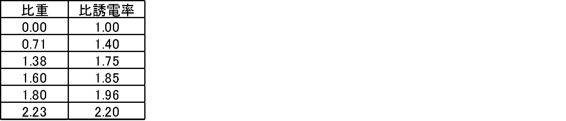
内層線路の作成
PTFEファインパウダー(標準比重(SSG):2.175)を2kgに、炭化水素系溶剤を押出助剤として410g混合し、3MPaで成型することで、直径49mmの予備成型品を作成した。この予備成型品をPTFEペースト押出成形機を使ってペースト押出し、直径3.5mmの丸棒状押出物を得た。この押出物を、80℃の電気炉で30分、その後200℃の電気炉で10分間加熱することで、押出助剤を蒸散させた。
押出助剤を蒸散させた上記押出物を360℃に加熱した電気炉に30分間入れてPTFEを焼成し、60℃/hrの降温速度で200℃まで冷却後、常温下に取り出すことで、徐冷して、内層線路を得た。内層線路の比重は2.060、比誘電率は2.10、誘電正接は0.00020であった。
内層線路の周りに、8mm幅にスリットした厚さ250μmの圧延未焼成未延伸PTFEテープを1mm間隔でS撚りで厚みが1mmになるように巻き付け、中間層1とした。中間層1の比重は1.595、比誘電率は1.85、誘電正接は0.00007であった。
中間層1の周りに、3倍延伸し、8mm幅にスリットした厚さ150μmの圧延未焼成未延伸PTFEテープを1mm間隔でZ撚りで厚みが1mmになるように巻き付け、中間層2とした。中間層2の比重は0.957、比誘電率は1.51、誘電正接は0.00004であった。
PTFEファインパウダー(標準比重(SSG):2.175)を2kgに、炭化水素系溶剤を押出助剤として410g混合し、3MPaで成型することで、直径49mmの予備成形品を作成した。この予備成形品をPTFEペースト押出成形機を使ってペースト押出し、外径15mm、内径7.5mmのチューブ状押出物を得た。この押出物を、50℃の電気炉で1時間、80℃の電気炉で1時間、その後200℃の電気炉で10分間加熱することで、押出助剤を蒸散させた。
押出助剤を蒸散させた上記押出物を300℃に設定した電気炉に30分間入れた後、2.5倍の長さに延伸することで比重0.657、比誘電率1.35、誘電正接0.00003の延伸PTFEチューブを作成した。このチューブを中間層2の外側に被せることで外層とし、誘電体導波線路を得た。
なお、挿入損失の絶対値が小さいほど、電磁波の突き抜けが少ない。
内層線路の作成
PTFEファインパウダー(標準比重(SSG):2.175)を2kgに、炭化水素系溶剤を押出助剤として410g混合し、3MPaで成型することで、直径49mmの予備成型品を作成した。この予備成型品をPTFEペースト押出成形機を使ってペースト押出し、直径3.5mmの丸棒状押出物を得た。この押出物を、80℃の電気炉で30分、その後200℃の電気炉で10分間、更に300℃の電気炉で30分間加熱することで、押出助剤を蒸散させて、内層線路を得た。内層線路の比重は1.595、比誘電率は1.85、誘電正接は0.00007であった。
内層線路の周りに、3倍延伸し、8mm幅にスリットした厚さ150μmの圧延未焼成未延伸PTFEテープを1mm間隔でZ撚りで厚みが1mmになるように巻き付け、中間層1とした。中間層1の比重は0.957、比誘電率は1.51、誘電正接は0.00004であった。
PTFEファインパウダー(標準比重(SSG):2.175)を2kgに、炭化水素系溶剤を押出助剤として410g混合し、3MPaで成型することで、直径49mmの予備成形品を作成した。この予備成形品をPTFEペースト押出成形機を使ってペースト押出し、外径15mm、内径7.5mmのチューブ状押出物を得た。この押出物を、50℃の電気炉で1時間、80℃の電気炉で1時間、その後200℃の電気炉で10分間加熱することで、押出助剤を蒸散させた。
押出助剤を蒸散させたチューブを300℃に設定した電気炉に30分間入れた後、2.5倍の長さに延伸することで比重0.657、比誘電率1.35、誘電正接0.00003の延伸PTFEチューブを作成した。このチューブを中間層1の外側に被せることで外層とし、誘電体導波線路を得た。
内層線路の作成
PTFEファインパウダー(標準比重(SSG):2.175)を2kgに、炭化水素系溶剤を押出助剤として410g混合し、3MPaで成形することで、直径49mmの予備成形品を作成した。この予備成形品をペースト押出成形機を使ってペースト押出し、3.5mm×7mm角の角棒状押出物を得た。この押出物を、50℃の電気炉で30分、80℃の電気炉で30分、その後200℃の電気炉で10分間加熱することで、押出助剤を蒸散させた。
押出助剤を蒸散させた上記押出物を360℃に加熱した電気炉に30分間入れてPTFEを焼成し、60℃/hrの降温速度で200℃まで冷却後、常温下に取り出すことで、徐冷して、内層線路を得た。内層線路の比重は2.158、比誘電率は2.15、誘電正接は0.00010であった。
内層線路の周りに、8mm幅にスリットした厚さ250μmの圧延未焼成未延伸PTFEテープを1mm間隔でS撚りで厚みが2mmになるように巻き付け、中間層1とした。中間層1の比重は1.595、比誘電率は1.85、誘電正接は0.00007であった。
中間層1の周りに、3倍延伸し、8mm幅にスリットした厚さ150μmの圧延未焼成未延伸PTFEテープを1mm間隔でZ撚りで厚みが2mmになるように巻き付け、中間層2とした。中間層2の比重は0.957、比誘電率は1.51、誘電正接は0.00004であった。
中間層2の周りに、5倍延伸し、8mm幅にスリットした厚さ100μmの圧延未焼成未延伸PTFEテープを1mm間隔でS撚りで厚みが1mmになるように巻き付け、外層とした。外層の比重は0.657、比誘電率は1.35、誘電正接は0.00003であった。
内層線路の作成
PTFEファインパウダー(標準比重(SSG):2.175)を2kgに、炭化水素系溶剤を押出助剤として410g混合し、3MPaで成形することで、直径49mmの予備成形品を作成した。この予備成形品をPTFEペースト押出成形機を使ってペースト押出し、直径3.5mmの丸棒状押出物を得た。この押出物を、50℃の電気炉で1時間、80℃の電気炉で1時間、その後200℃の電気炉で10分間加熱することで、押出助剤を蒸散させて、内層線路を得た。内層線路の比重は2.158、比誘電率は2.15、誘電正接は0.00010であった。
PTFEファインパウダー(標準比重(SSG):2.175)を2kgに、炭化水素系溶剤を押出助剤として410g混合し、3MPaで成型することで、直径49mmの予備成形品を作成した。この予備成形品をPTFEペースト押出成形機を使ってペースト押出し、外径6.5mm、内径3.5mmのチューブ状押出物を得た。この押出物を、50℃の電気炉で1時間、80℃の電気炉で1時間、その後200℃の電気炉で10分間加熱することで、押出助剤を蒸散させた。このチューブを内層線路の外側に被せることで中間層1とした。中間層1の比重は1.80、比誘電率は1.96、誘電正接は0.00009であった。
中間層1と同様の方法で外径10mm、内径6.5mmのチューブ状押出物を得た。この押出物を、50℃の電気炉で1時間、80℃の電気炉で1時間、その後200℃の電気炉で10分間加熱することで、押出助剤を蒸散させた。このチューブを300℃に設定した電気炉に30分間入れた後、2.5倍の長さに延伸することで比重1.6、比誘電率1.85、誘電正接0.00007の延伸PTFEチューブを作成した。このチューブを中間層1の外側にかぶせることで中間層2とした。
中間層1と同様の方法で外径18mm、内径10mmのチューブ状押出物を得た。この押出物を、50℃の電気炉で1時間、80℃の電気炉で1時間、その後200℃の電気炉で10分間加熱することで、押出助剤を蒸散させた。このチューブを300℃に設定した電気炉に30分間入れた後、3倍の長さに延伸することで比重0.71、比誘電率1.4、誘電正接0.00003の延伸PTFEチューブを作成した。このチューブを中間層2の外側にかぶせることで外層とした。
PTFEファインパウダー(標準比重(SSG):2.175)を2kgに、炭化水素系溶剤を押出助剤として410g混合し、3MPaで成型することで、直径49mmの予備成型品を作成した。この予備成型品をPTFEペースト押出成形機を使ってペースト押出し、直径9mmの丸棒状押出物を得た。この押出物を、50℃の電気炉で1時間、100℃の電気炉で1時間、その後200℃の電気炉で10分間加熱することで、押出助剤を蒸散させた。
押出助剤を蒸散させた上記押出物を340℃に加熱した電気炉に15分間入れることで、PTFEを焼成した。焼成したPTFE丸棒を、直ちに常温雰囲気中に置くことで表面を急冷し、径方向に外側に向かって比誘電率が徐々に低下する誘電体導波線路を得た。
上記で得られた誘電体導波線路の中心部の比重は2.23、比誘電率は2.20であり、中心から径方向に約2.3mmの部分の比重は2.17、比誘電率は2.08であり、外周部の比重は2.10、比誘電率は1.95であった。
PTFEファインパウダー(標準比重(SSG):2.175)を2kgに、炭化水素系溶剤を押出助剤として410g混合し、3MPaで成形することで、直径49mm内径16mmの予備成形品を作成した。この予備成形品をPTFEペースト押出成形機を使って0.511mm銀メッキ銅線上に被覆押出し、直径9.0mmの被覆押出物を得た。この押出物を、50℃の電気炉で1時間、80℃の電気炉で1時間、その後200℃の電気炉で10分間加熱することで、押出助剤を蒸散させた。
押出助剤を蒸散させた上記押出物を長さ2mに切断し、銀メッキ銅線の両端に直流電源を接続し、7.5Vを印加したところ15Aの電流が流れた。上記押出物の表面が250℃に達したところで、電圧印加をやめ、常温まで、冷却した。その後銀メッキ線を引き抜いて、誘電体導波線路を得た。
上記で得られた誘電体導波線路の中心(銅線が位置していた部分)付近の比重は2.23、比誘電率は2.20であり、中心から径方向に約2.3mmの部分の比重は2.17、比誘電率は2.08であり、外周部の比重は2.10、比誘電率は1.95であった。
内層線路の作成
PTFEファインパウダー(標準比重(SSG):2.175)を2kgに、炭化水素系溶剤を押出助剤として410g混合し、3MPaで成型することで、直径49mmの予備成型品を作成した。この予備成型品をPTFEペースト押出成形機を使ってペースト押出し、直径3.5mmの丸棒状押出物を得た。この押出物を、80℃の電気炉で30分、その後200℃の電気炉で10分間加熱することで、押出助剤を蒸散させた。
押出助剤を蒸散させた上記押出物を360℃に加熱した電気炉に30分間入れてPTFEを焼成し、60℃/hrの降温速度で200℃まで冷却後、常温下に取り出すことで、徐冷して、内層線路を得た。内層線路の比重は2.060、比誘電率は2.10、誘電正接は0.00020であった。
内層線路の周りに、ポリエチレン(PE)から得られた発泡PEチューブをかぶせた。中間層1の内径は3.6mm、外径は10.5mm、比重は0.396、比誘電率は1.56、誘電正接は0.00003であった。
中間層1の周りに、PEから得られた発泡PEシート(厚み9mm、幅10mm)を1重となるように巻き付けて外層とし、誘電体導波線路を得た。上記外層の比重は0.01569、比誘電率は1.03、誘電正接は0.00002であった。
内層線路の作成
PTFEファインパウダー(標準比重(SSG):2.175)を2kgに、炭化水素系溶剤を押出助剤として410g混合し、3MPaで成型することで、直径49mmの予備成型品を作成した。この予備成型品をPTFEペースト押出成形機を使ってペースト押出し、直径3.5mmの丸棒状押出物を得た。この押出物を、80℃の電気炉で30分、その後200℃の電気炉で10分間加熱することで、押出助剤を蒸散させた。
押出助剤を蒸散させた上記押出物を360℃に加熱した電気炉に30分間入れてPTFEを焼成し、60℃/hrの降温速度で200℃まで冷却後、常温下に取り出すことで、徐冷して、内層線路を得た。内層線路の比重は2.060、比誘電率は2.10、誘電正接は0.00020であった。
内層線路の周りに、PFAから得られた発泡PFAチューブをかぶせた。中間層1の内径は3.6mm、外径は10.5mm、比重は1.2、比誘電率は1.5、誘電正接は0.0002であった。
中間層1の周りに、PFAから得られた発泡PFAシート(厚み9mm、幅10mm)を1重となるように巻き付けて外層とし、誘電体導波線路を得た。上記外層の比重は1.0、比誘電率は1.2、誘電正接は0.00008であった。
内層線路の作成
PTFEファインパウダー(標準比重(SSG):2.175)を2kgに、炭化水素系溶剤を押出助剤として410g混合し、3MPaで成型することで、直径49mmの予備成型品を作成した。この予備成型品をPTFEペースト押出成形機を使ってペースト押出し、直径3.5mmの丸棒状押出物を得た。この押出物を、80℃の電気炉で30分、その後200℃の電気炉で10分間加熱することで、押出助剤を蒸散させた。
押出助剤を蒸散させた上記押出物を360℃に加熱した電気炉に30分間入れてPTFEを焼成し、60℃/hrの降温速度で200℃まで冷却後、常温下に取り出すことで、徐冷して、内層線路を得た。内層線路の比重は2.060、比誘電率は2.10、誘電正接は0.00020であった。
内層線路の周りに、FEPから得られた発泡FEPチューブをかぶせた。中間層1の内径は3.6mm、外径は10.5mm、比重は1.1、比誘電率は1.5、誘電正接は0.0002であった。
中間層1の周りに、FEPから得られた発泡FEPシート(厚み9mm、幅10mm)を1重となるように巻き付けて外層とし、誘電体導波線路を得た。上記外層の比重は1.0、比誘電率は1.1、誘電正接は0.00007であった。
内層線路の作成
PTFEファインパウダー(標準比重(SSG):2.175)を2kgに、炭化水素系溶剤を押出助剤として410g混合し、3MPaで成型することで、直径49mmの予備成型品を作成した。この予備成型品をPTFEペースト押出成形機を使ってペースト押出し、直径3.5mmの丸棒状押出物を得た。この押出物を、50℃の電気炉で1時間、80℃の電気炉で1時間、その後200℃の電気炉で10分間加熱することで、押出助剤を蒸散させた。
押出助剤を蒸散させた上記押出物を360℃に加熱した電気炉に30分間入れてPTFEを焼成し、60℃/hrの降温速度で200℃まで冷却後、常温下に取り出すことで、徐冷し、内層線路を得た。内層線路の比重は2.060、比誘電率は2.10、誘電正接は0.0002であった。
PTFEファインパウダー(標準比重(SSG):2.175)を2kgに、炭化水素系溶剤を押出助剤として410g混合し、3MPaで成型することで、直径49mmの予備成形品を作成した。この予備成形品をPTFEペースト押出成形機を使ってペースト押出し、外径15mm、内径3.5mmのチューブ状押出物を得た。この押出物を、50℃の電気炉で1時間、80℃の電気炉で1時間、その後200℃の電気炉で10分間加熱することで、押出助剤を蒸散させた。
この未焼成PTFEチューブを、300℃の電気炉に1時間入れ、更に2.5倍の長さに延伸し、全長を維持したまま常温度まで冷却することで、比重0.582、比誘電率1.31、誘電正接は0.00003の外層チューブを得た。
この外層チューブを上記内層線路に被せ、外層とした。
内層線路の作成
PTFEファインパウダー(標準比重(SSG):2.175)を2kgに、炭化水素系溶剤を押出助剤として410g混合し、3MPaで成型することで、直径49mmの予備成型品を作成した。この予備成型品をPTFEペースト押出成形機を使ってペースト押出し、3.5mm×7mm角の角棒状押出物を得た。この押出物を、50℃の電気炉で1時間、80℃の電気炉で1時間、その後200℃の電気炉で10分間加熱することで、押出助剤を蒸散させた。
押出助剤を蒸散させた上記押出物を360℃に加熱した電気炉に30分間入れてPTFEを焼成し、60℃/hrの降温速度で200℃まで冷却後、常温下に取り出すことで、徐冷し、内層線路を得た。上記内層線路の比重は2.158、比誘電率は2.15、誘電正接は0.00010であった。
内層線路の周りに、8mm幅にスリットした厚さ100μmの圧延未焼成未延伸PTFEテープを1mm間隔でS撚りで数回巻き付け、5mm厚みの外層とした。外層の比重は0.657、比誘電率は1.35、誘電正接は0.00003であった。
Claims (4)
- 中心誘電体A1と、中心誘電体A1の周囲に設けられた誘電体層A2と、誘電体層A2の周囲に設けられた誘電体層A3とを備える誘電体導波線路であって、
中心誘電体A1は、ポリテトラフルオロエチレンを含み、
中心誘電体A1、誘電体層A2及び誘電体層A3の25℃、6GHzにおける比誘電率をそれぞれεA1、εA2及びεA3と表すとき、
εA1が2.20以下であり、εA2が1.90以下であり、εA3が1.55以下であり、εA1>εA2>εA3である
誘電体導波線路。 - 中心誘電体A1、誘電体層A2及び誘電体層A3の25℃、6GHzにおける誘電正接をそれぞれtanδA1、tanδA2及びtanδA3と表すとき、tanδA1が2.20×10⁻⁴以下であり、tanδA2が1.20×10⁻⁴以下であり、tanδA3が1.00×10⁻⁴以下である請求項1記載の誘電体導波線路。
- 誘電体層A2及びA3は、ポリテトラフルオロエチレン、テトラフルオロエチレン/ヘキサフルオロプロピレン共重合体、テトラフルオロエチレン/パーフルオロ(アルキルビニルエーテル)共重合体及びポリオレフィンからなる群より選択される少なくとも1種の樹脂Aを含む請求項1又は2記載の誘電体導波線路。
- ポリテトラフルオロエチレンを含む誘電体Bを備える誘電体導波線路であって、
誘電体Bは、同一の材料で継ぎ目なく一体に形成されており、かつ、径方向に外側に向かって25℃、6GHzにおける比誘電率が徐々に低くなる
誘電体導波線路。
Priority Applications (4)
| Application Number | Priority Date | Filing Date | Title |
|---|---|---|---|
| KR1020227027343A KR102727278B1 (ko) | 2020-02-20 | 2021-02-19 | 유전체 도파 선로 |
| EP21757223.9A EP4099497A4 (en) | 2020-02-20 | 2021-02-19 | DIELECTRIC WAVEGUIDE LINE |
| CN202180014253.2A CN115136409B (zh) | 2020-02-20 | 2021-02-19 | 电介质波导线路 |
| US17/889,733 US12469945B2 (en) | 2020-02-20 | 2022-08-17 | Dielectric waveguide line |
Applications Claiming Priority (2)
| Application Number | Priority Date | Filing Date | Title |
|---|---|---|---|
| JP2020-027067 | 2020-02-20 | ||
| JP2020027067 | 2020-02-20 |
Related Child Applications (1)
| Application Number | Title | Priority Date | Filing Date |
|---|---|---|---|
| US17/889,733 Continuation US12469945B2 (en) | 2020-02-20 | 2022-08-17 | Dielectric waveguide line |
Publications (1)
| Publication Number | Publication Date |
|---|---|
| WO2021167073A1 true WO2021167073A1 (ja) | 2021-08-26 |
Family
ID=77390844
Family Applications (1)
| Application Number | Title | Priority Date | Filing Date |
|---|---|---|---|
| PCT/JP2021/006402 Ceased WO2021167073A1 (ja) | 2020-02-20 | 2021-02-19 | 誘電体導波線路 |
Country Status (6)
| Country | Link |
|---|---|
| US (1) | US12469945B2 (ja) |
| EP (1) | EP4099497A4 (ja) |
| JP (1) | JP7082304B2 (ja) |
| KR (1) | KR102727278B1 (ja) |
| CN (1) | CN115136409B (ja) |
| WO (1) | WO2021167073A1 (ja) |
Families Citing this family (2)
| Publication number | Priority date | Publication date | Assignee | Title |
|---|---|---|---|---|
| US12160041B2 (en) * | 2021-04-30 | 2024-12-03 | The Board Of Trustees Of The University Of Alabama | Miniaturized reflector antenna |
| US20230282394A1 (en) * | 2022-03-07 | 2023-09-07 | John Mezzalingua Associates, LLC | Radio frequency (rf) plenum cable with reduced insertion loss |
Citations (8)
| Publication number | Priority date | Publication date | Assignee | Title |
|---|---|---|---|---|
| JPS5813702U (ja) * | 1981-07-17 | 1983-01-28 | 株式会社潤工社 | 伝送線路 |
| JPS5875301A (ja) * | 1982-07-09 | 1983-05-07 | Junkosha Co Ltd | 伝送線路 |
| JPS6469106A (en) * | 1987-08-17 | 1989-03-15 | Gore & Ass | Dielectric waveguide with higher degree mode suppressing layer |
| JP2001357730A (ja) | 2000-06-15 | 2001-12-26 | Daikin Ind Ltd | 高周波信号伝送用製品およびその製法 |
| WO2005019320A1 (ja) | 2003-08-25 | 2005-03-03 | Daikin Industries, Ltd. | 混合ポリテトラフルオロエチレン粉体及びポリテトラフルオロエチレン多孔成形体及びこれらの製造方法、ポリテトラフルオロエチレン多孔発泡成形体並びに高周波信号伝送用製品 |
| WO2012007760A1 (en) | 2010-07-15 | 2012-01-19 | John William Carson | Improved fertilisers for sustainable farming |
| WO2016159314A1 (ja) | 2015-03-31 | 2016-10-06 | ダイキン工業株式会社 | 誘電体導波線路 |
| WO2018068914A1 (de) * | 2016-10-10 | 2018-04-19 | Rosenberger Hochfrequenztechnik Gmbh & Co. Kg | Dielektrisches wellenleiterkabel |
Family Cites Families (6)
| Publication number | Priority date | Publication date | Assignee | Title |
|---|---|---|---|---|
| US4463329A (en) * | 1978-08-15 | 1984-07-31 | Hirosuke Suzuki | Dielectric waveguide |
| US8877331B2 (en) * | 2007-01-17 | 2014-11-04 | MicroGREEN Polymers | Multi-layered foamed polymeric objects having segmented and varying physical properties and related methods |
| JP2008242449A (ja) | 2007-02-27 | 2008-10-09 | Keio Gijuku | ポリマー並列光導波路とその製造方法 |
| JP2016195295A (ja) | 2015-03-31 | 2016-11-17 | ダイキン工業株式会社 | 誘電体導波線路 |
| EP3651264B1 (en) * | 2016-03-16 | 2022-12-21 | TE Connectivity Germany GmbH | Low-loss dielectric waveguide for transmission of millimeter-wave signals and cable comprising the same |
| JP2025075301A (ja) | 2023-10-31 | 2025-05-15 | 宇部マテリアルズ株式会社 | 防ダニシート |
-
2021
- 2021-02-19 KR KR1020227027343A patent/KR102727278B1/ko active Active
- 2021-02-19 CN CN202180014253.2A patent/CN115136409B/zh active Active
- 2021-02-19 EP EP21757223.9A patent/EP4099497A4/en active Pending
- 2021-02-19 WO PCT/JP2021/006402 patent/WO2021167073A1/ja not_active Ceased
- 2021-02-19 JP JP2021025120A patent/JP7082304B2/ja active Active
-
2022
- 2022-08-17 US US17/889,733 patent/US12469945B2/en active Active
Patent Citations (8)
| Publication number | Priority date | Publication date | Assignee | Title |
|---|---|---|---|---|
| JPS5813702U (ja) * | 1981-07-17 | 1983-01-28 | 株式会社潤工社 | 伝送線路 |
| JPS5875301A (ja) * | 1982-07-09 | 1983-05-07 | Junkosha Co Ltd | 伝送線路 |
| JPS6469106A (en) * | 1987-08-17 | 1989-03-15 | Gore & Ass | Dielectric waveguide with higher degree mode suppressing layer |
| JP2001357730A (ja) | 2000-06-15 | 2001-12-26 | Daikin Ind Ltd | 高周波信号伝送用製品およびその製法 |
| WO2005019320A1 (ja) | 2003-08-25 | 2005-03-03 | Daikin Industries, Ltd. | 混合ポリテトラフルオロエチレン粉体及びポリテトラフルオロエチレン多孔成形体及びこれらの製造方法、ポリテトラフルオロエチレン多孔発泡成形体並びに高周波信号伝送用製品 |
| WO2012007760A1 (en) | 2010-07-15 | 2012-01-19 | John William Carson | Improved fertilisers for sustainable farming |
| WO2016159314A1 (ja) | 2015-03-31 | 2016-10-06 | ダイキン工業株式会社 | 誘電体導波線路 |
| WO2018068914A1 (de) * | 2016-10-10 | 2018-04-19 | Rosenberger Hochfrequenztechnik Gmbh & Co. Kg | Dielektrisches wellenleiterkabel |
Non-Patent Citations (1)
| Title |
|---|
| See also references of EP4099497A4 |
Also Published As
| Publication number | Publication date |
|---|---|
| KR20220120697A (ko) | 2022-08-30 |
| EP4099497A1 (en) | 2022-12-07 |
| JP2021132375A (ja) | 2021-09-09 |
| CN115136409B (zh) | 2025-09-09 |
| KR102727278B1 (ko) | 2024-11-08 |
| EP4099497A4 (en) | 2024-02-21 |
| US12469945B2 (en) | 2025-11-11 |
| JP7082304B2 (ja) | 2022-06-08 |
| US20220407206A1 (en) | 2022-12-22 |
| CN115136409A (zh) | 2022-09-30 |
Similar Documents
| Publication | Publication Date | Title |
|---|---|---|
| JP6414632B2 (ja) | 誘電体導波線路 | |
| JP6134818B2 (ja) | テトラフルオロエチレン/ヘキサフルオロプロピレン系共重合体及び電線 | |
| JP5844764B2 (ja) | テトラフルオロエチレン/ヘキサフルオロプロピレン共重合体の製造方法 | |
| JP4816084B2 (ja) | 高周波信号伝送用製品及びその製造方法並びに高周波伝送ケーブル | |
| US12469945B2 (en) | Dielectric waveguide line | |
| JP6908184B2 (ja) | 撚り電線およびその製造方法 | |
| JP4827372B2 (ja) | ポリテトラフルオロエチレン系樹脂製チューブ及びその製造方法 | |
| JP2012136020A (ja) | 多層チューブ、及び、該多層チューブの製造方法 | |
| CN107430912B (zh) | 电线的制造方法 | |
| JP7108223B1 (ja) | 含フッ素共重合体 | |
| JP7177378B2 (ja) | 含フッ素共重合体 | |
| JP2016195295A (ja) | 誘電体導波線路 | |
| JP7144698B2 (ja) | 配線板 | |
| JP2025125746A (ja) | 電線の製造方法および電線 |
Legal Events
| Date | Code | Title | Description |
|---|---|---|---|
| 121 | Ep: the epo has been informed by wipo that ep was designated in this application |
Ref document number: 21757223 Country of ref document: EP Kind code of ref document: A1 |
|
| ENP | Entry into the national phase |
Ref document number: 20227027343 Country of ref document: KR Kind code of ref document: A |
|
| ENP | Entry into the national phase |
Ref document number: 2021757223 Country of ref document: EP Effective date: 20220901 |
|
| NENP | Non-entry into the national phase |
Ref country code: DE |
|
| WWG | Wipo information: grant in national office |
Ref document number: 202180014253.2 Country of ref document: CN |