WO2021171663A1 - ロータ、およびモータ - Google Patents
ロータ、およびモータ Download PDFInfo
- Publication number
- WO2021171663A1 WO2021171663A1 PCT/JP2020/034772 JP2020034772W WO2021171663A1 WO 2021171663 A1 WO2021171663 A1 WO 2021171663A1 JP 2020034772 W JP2020034772 W JP 2020034772W WO 2021171663 A1 WO2021171663 A1 WO 2021171663A1
- Authority
- WO
- WIPO (PCT)
- Prior art keywords
- slit
- magnet
- axial direction
- viewed
- angle
- Prior art date
- Legal status (The legal status is an assumption and is not a legal conclusion. Google has not performed a legal analysis and makes no representation as to the accuracy of the status listed.)
- Ceased
Links
Images

Classifications
-
- H—ELECTRICITY
- H02—GENERATION; CONVERSION OR DISTRIBUTION OF ELECTRIC POWER
- H02K—DYNAMO-ELECTRIC MACHINES
- H02K1/00—Details of the magnetic circuit
- H02K1/06—Details of the magnetic circuit characterised by the shape, form or construction
- H02K1/22—Rotating parts of the magnetic circuit
- H02K1/27—Rotor cores with permanent magnets
- H02K1/2706—Inner rotors
- H02K1/272—Inner rotors the magnetisation axis of the magnets being perpendicular to the rotor axis
- H02K1/274—Inner rotors the magnetisation axis of the magnets being perpendicular to the rotor axis the rotor consisting of two or more circumferentially positioned magnets
- H02K1/2753—Inner rotors the magnetisation axis of the magnets being perpendicular to the rotor axis the rotor consisting of two or more circumferentially positioned magnets the rotor consisting of magnets or groups of magnets arranged with alternating polarity
- H02K1/276—Magnets embedded in the magnetic core, e.g. interior permanent magnets [IPM]
- H02K1/2766—Magnets embedded in the magnetic core, e.g. interior permanent magnets [IPM] having a flux concentration effect
-
- H—ELECTRICITY
- H02—GENERATION; CONVERSION OR DISTRIBUTION OF ELECTRIC POWER
- H02K—DYNAMO-ELECTRIC MACHINES
- H02K1/00—Details of the magnetic circuit
- H02K1/06—Details of the magnetic circuit characterised by the shape, form or construction
- H02K1/22—Rotating parts of the magnetic circuit
- H02K1/28—Means for mounting or fastening rotating magnetic parts on to, or to, the rotor structures
-
- H—ELECTRICITY
- H02—GENERATION; CONVERSION OR DISTRIBUTION OF ELECTRIC POWER
- H02K—DYNAMO-ELECTRIC MACHINES
- H02K2213/00—Specific aspects, not otherwise provided for and not covered by codes H02K2201/00 - H02K2211/00
- H02K2213/03—Machines characterised by numerical values, ranges, mathematical expressions or similar information
Definitions
- the present invention relates to a rotor and a motor.
- Patent Document 1 describes a rotor provided with a permanent magnet having a radial cross section having an arc shape and a convexly curved surface facing the rotation axis side of the rotor.
- one of the objects of the present invention is to provide a rotor having a structure capable of improving the torque of the motor, and a motor including such a rotor.
- One aspect of the rotor of the present invention is a rotor provided in a motor that can rotate about a central axis, and includes a rotor core having a plurality of slits, a plurality of magnets provided in the plurality of slits, and the like.
- the plurality of slits are located apart from the arc-shaped first slit which is convex inward in the radial direction when viewed in the axial direction and the radial inward side of the first slit, and are convex inward in the radial direction when viewed in the axial direction.
- the plurality of magnets are provided in the first slit and have an arcuate first magnet extending along the first slit when viewed in the axial direction, and are provided in the second slit and when viewed in the axial direction. It includes an arc-shaped second magnet extending along the second slit and an arc-shaped third magnet provided in the third slit and extending along the third slit when viewed in the axial direction.
- both ends of the first magnet are arranged apart from both ends of the first slit.
- both ends of the second magnet are arranged apart from both ends of the second slit.
- both ends of the third magnet are arranged apart from both ends of the third slit.
- the first angle formed by the line segment connecting the reference point and the end of the first slit and the line segment connecting the reference point and the end of the first magnet is the reference point and the first. It is larger than the second angle formed by the line segment connecting the ends of the two slits and the line segment connecting the reference point and the end of the second magnet. Seen in the axial direction, the second angle is a third formed by a line segment connecting the reference point and the end of the third slit and a line segment connecting the reference point and the end of the third magnet. Greater than the angle.
- One aspect of the motor of the present invention includes the above rotor and a stator located radially outside the rotor.
- the torque of the motor can be improved.
- FIG. 1 is a cross-sectional view schematically showing the motor of the present embodiment.
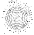
- FIG. 2 is a cross-sectional view showing the rotor of the present embodiment, and is a cross-sectional view taken along the line II-II in FIG.
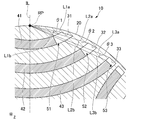
- FIG. 3 is a cross-sectional view showing a part of the rotor of the present embodiment, and is a partially enlarged view of FIG.
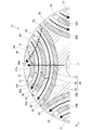
- FIG. 4 is a cross-sectional view for explaining the flow of magnetic flux in the rotor of the present embodiment.
- the Z-axis direction shown in each figure is a vertical direction in which the positive side is the "upper side” and the negative side is the “lower side”.
- the central axis J appropriately shown in each figure is a virtual line that is parallel to the Z-axis direction and extends in the vertical direction.
- the axial direction of the central axis J that is, the direction parallel to the vertical direction
- the radial direction centered on the central axis J is simply referred to as "radial direction”.
- the circumferential direction centered on is simply called the "circumferential direction”.
- the vertical direction, the upper side, and the lower side are simply names for explaining the arrangement relations of each part, and the actual arrangement relations, etc. are the arrangement relations, etc. other than the arrangement relations, etc. indicated by these names. There may be.
- the motor 1 of the present embodiment shown in FIG. 1 is an inner rotor type motor.
- the motor 1 of the present embodiment includes a housing 2, a rotor 10, a stator 3, a bearing holder 4, and bearings 5a and 5b.
- the housing 2 houses the rotor 10, the stator 3, the bearing holder 4, and the bearings 5a and 5b inside.
- the bottom of the housing 2 holds the bearing 5b.
- the bearing holder 4 holds the bearing 5a.
- the bearings 5a and 5b are, for example, ball bearings.
- the stator 3 is located on the outer side in the radial direction of the rotor 10.
- the stator 3 has a stator core 3a, an insulator 3d, and a plurality of coils 3e.
- the stator core 3a has a core back 3b and a plurality of teeth 3c.
- the core back 3b is an annular shape centered on the central axis J.
- the plurality of teeth 3c extend radially inward from the core back 3b. Although not shown, the plurality of teeth 3c are arranged at equal intervals along the circumferential direction.
- the plurality of coils 3e are mounted on the stator core 3a via the insulator 3d.
- the rotor 10 can rotate about the central axis J.
- the rotor 10 includes a shaft 11, a rotor core 20, and a plurality of magnets 40.
- the shaft 11 is a columnar shape extending in the axial direction about the central axis J.
- the shaft 11 is rotatably supported around the central axis J by bearings 5a and 5b.
- the rotor core 20 is a magnetic material.
- the rotor core 20 is fixed to the outer peripheral surface of the shaft 11.
- the rotor core 20 has a through hole 21 that penetrates the rotor core 20 in the axial direction. As shown in FIG. 2, the through hole 21 has a circular shape centered on the central axis J when viewed in the axial direction.
- the shaft 11 is passed through the through hole 21.
- the shaft 11 is fixed in the through hole 21 by, for example, press fitting or the like.
- the rotor core 20 is configured by, for example, a plurality of electromagnetic steel sheets laminated in the axial direction.
- the rotor core 20 has a plurality of slits 30.
- the plurality of slits 30 penetrate the rotor core 20 in the axial direction, for example.
- the plurality of slits 30 extend along a plane orthogonal to the axial direction.
- the plurality of slits 30 include a first slit 31, a second slit 32, and a third slit 33.
- the first slit 31, the second slit 32, and the third slit 33 have an arc shape that is convex inward in the radial direction when viewed in the axial direction.
- the second slit 32 is located apart from the first slit 31 in the radial direction.
- the third slit 33 is located apart from the inside of the second slit 32 in the radial direction.
- the first slit 31, the second slit 32, and the third slit 33 are arranged side by side at equal intervals in the radial direction.
- the first slit 31, the second slit 32, and the third slit 33 are, for example, arcuate shapes that are concentric with each other when viewed in the axial direction.
- the arc radius of the second slit 32 is larger than the arc radius of the first slit 31.
- the arc radius of the third slit 33 is larger than the arc radius of the second slit 32.
- the width of the first slit 31, the width of the second slit 32, and the width of the third slit 33 are, for example, the same as each other.
- a certain parameter is the same as each other includes not only a case where a certain parameter is exactly the same as each other but also a case where a certain parameter is substantially the same as each other.
- the parameters are substantially the same as each other includes, for example, that the parameters are slightly deviated from each other within the tolerance.
- each slit 30 When viewed in the axial direction, the distance between the first slit 31 and the second slit 32 and the distance between the second slit 32 and the third slit 33 are larger than the width of each slit 30.
- the width of each slit 30 is the dimension of each slit 30 in the direction orthogonal to the direction in which each slit 30 extends in an arc shape when viewed in the axial direction.
- the direction in which the slit 30 extends in an arc shape when viewed in the axial direction is referred to as the "stretching direction".
- the direction in which the first slit 31 extends in an arc shape when viewed in the axial direction is referred to as a "first stretching direction”.
- the direction in which the second slit 32 extends in an arc shape when viewed in the axial direction is referred to as a "second stretching direction”.
- the direction in which the third slit 33 extends in an arc shape when viewed in the axial direction is referred to as a "third stretching direction”.
- both ends of the first slit 31, both ends of the second slit 32, and both ends of the third slit 33 are located at the radial outer edges of the rotor core 20.
- Both ends of the first slit 31 are both ends of the first slit 31 in the first stretching direction.
- the both ends of the second slit 32 are both ends of the second slit 32 in the second stretching direction.
- Both ends of the third slit 33 are both ends of the third slit 33 in the third stretching direction.
- Both ends of the first slit 31, both ends of the second slit 32, and both ends of the third slit 33 are located, for example, slightly radially inward from the outer peripheral surface of the rotor core 20.
- the inner side surfaces at both ends of each slit 30 are arranged along the outer peripheral surface of the rotor core 20 when viewed in the axial direction.
- the radial positions of both ends of the first slit 31, the radial positions of both ends of the second slit 32, and the radial positions of both ends of the third slit 33 are the same as each other. Both ends of the first slit 31, both ends of the second slit 32, and both ends of the third slit 33 are arranged side by side at the outer edge of the rotor core 20 in the radial direction at intervals along the circumferential direction. ..
- the dimension of the second slit 32 in the second stretching direction is larger than the dimension of the first slit 31 in the first stretching direction.
- the dimension of the third slit 33 in the third stretching direction is larger than the dimension of the second slit 32 in the second stretching direction.
- first slit 31, the second slit 32, and the third slit 33 are provided along the circumferential direction.
- a plurality of the first slit 31, the second slit 32, and the third slit 33 are provided along the circumferential direction.
- the plurality of first slits 31 are arranged at equal intervals along the circumferential direction.
- the plurality of second slits 32 are arranged at equal intervals over one circumference along the circumferential direction.
- the plurality of third slits 33 are arranged at equal intervals along the circumferential direction.
- Each group including the first slit 31, the second slit 32, and the third slit 33, which are arranged at intervals in the radial direction, is arranged in such a posture that the groups adjacent to each other in the circumferential direction are tilted by 90 ° in the circumferential direction. It has the same configuration except that it is.
- the plurality of magnets 40 are provided in the plurality of slits 30.
- One magnet 40 is provided in each slit 30.
- the magnet 40 is a ferrite magnet.
- the plurality of magnets 40 include a first magnet 41, a second magnet 42, and a third magnet 43.
- the first magnet 41 is provided in the first slit 31.
- the first magnet 41 is provided for each first slit 31.
- four first magnets 41 are provided.
- the first magnet 41 has an arc shape extending along the first slit 31 when viewed in the axial direction.
- the first magnet 41 has an arc shape that is convex inward in the radial direction when viewed in the axial direction.
- the first magnet 41 is fitted in the first slit 31.
- the radial side surfaces of the first magnet 41 are in contact with the radial side surfaces of the first slit 31, respectively.
- both ends of the first magnet 41 are arranged apart from both ends of the first slit 31. Both ends of the first magnet 41 are both ends of the first magnet 41 in the first stretching direction. Both end faces of the first magnet 41 in the first stretching direction are orthogonal to, for example, the first stretching direction.
- First flux barrier portions 51 are provided on both sides of the first magnet 41 in the first stretching direction.
- the first flux barrier portion 51 is a portion of the first slit 31 in which the first magnet 41 is not arranged. In the present embodiment, the first flux barrier portion 51 is a gap portion.
- the first magnet 41 is provided, for example, over the entire axial direction in the first slit 31.
- the second magnet 42 is provided in the second slit 32.
- the second magnet 42 is provided for each second slit 32.
- four second magnets 42 are provided.
- the second magnet 42 has an arc shape extending along the second slit 32 when viewed in the axial direction.
- the second magnet 42 has an arc shape that is convex inward in the radial direction when viewed in the axial direction.
- the second magnet 42 is fitted in the second slit 32.
- the radial side surfaces of the second magnet 42 are in contact with the radial side surfaces of the second slit 32, respectively.
- both ends of the second magnet 42 are arranged apart from both ends of the second slit 32. Both ends of the second magnet 42 are both ends of the second magnet 42 in the second stretching direction. Both end faces of the second magnet 42 in the second stretching direction are orthogonal to, for example, the second stretching direction.
- Second flux barrier portions 52 are provided on both sides of the second magnet 42 in the second stretching direction.
- the second flux barrier portion 52 is a portion of the second slit 32 in which the second magnet 42 is not arranged.
- the second flux barrier portion 52 is a gap portion.
- the dimension of the second flux barrier portion 52 in the second stretching direction is smaller than the dimension of the first flux barrier portion 51 in the first stretching direction.
- the second magnet 42 is provided, for example, over the entire axial direction in the second slit 32.
- the third magnet 43 is provided in the third slit 33.
- the third magnet 43 is provided for each third slit 33.
- four third magnets 43 are provided.
- the third magnet 43 has an arc shape extending along the third slit 33 when viewed in the axial direction.
- the third magnet 43 has an arc shape that is convex inward in the radial direction when viewed in the axial direction.
- the third magnet 43 is fitted in the third slit 33.
- the radial side surfaces of the third magnet 43 are in contact with the radial side surfaces of the third slit 33, respectively.
- Both ends of the third magnet 43 are arranged apart from both ends of the third slit 33. Both ends of the third magnet 43 are both ends of the third magnet 43 in the third stretching direction. Both end faces of the third magnet 43 in the third stretching direction are orthogonal to, for example, the third stretching direction.
- Third flux barrier portions 53 are provided on both sides of the third magnet 43 in the third stretching direction.
- the third flux barrier portion 53 is a portion of the third slit 33 in which the third magnet 43 is not arranged.
- the third flux barrier portion 53 is a gap portion.
- the dimension of the third flux barrier portion 53 in the third stretching direction is smaller than the dimension of the second flux barrier portion 52 in the second stretching direction.
- the third magnet 43 is provided, for example, over the entire axial direction in the third slit 33.
- the magnetic poles of the first magnet 41, the magnetic poles of the second magnet 42, and the magnetic poles of the third magnet 43 are arranged along the radial direction.
- the first magnet 41 includes a first magnet 41a and a first magnet 41b in which magnetic poles are arranged so as to be reversed in the radial direction.
- the first magnet 41a and the first magnet 41b are alternately arranged along the circumferential direction.
- the second magnet 42 includes a second magnet 42a and a second magnet 42b in which the magnetic poles are arranged so as to be radially inverted from each other.
- the second magnet 42a and the second magnet 42b are alternately arranged along the circumferential direction.
- the third magnet 43 includes a third magnet 43a and a third magnet 43b in which the magnetic poles are arranged so as to be reversed in the radial direction.
- the third magnet 43a and the third magnet 43b are alternately arranged along the circumferential direction.
- the first magnet 41a, the second magnet 42a, and the third magnet 43a are the same in each set including the first slit 31, the second slit 32, and the third slit 33, which are arranged at intervals in the radial direction. It is arranged in each slit of the set. As a result, the first magnet 41a, the second magnet 42a, and the third magnet 43a are arranged side by side with an interval in the radial direction.
- the first magnet 41b, the second magnet 42b, and the third magnet 43b are the same in each set including the first slit 31, the second slit 32, and the third slit 33, which are arranged at intervals in the radial direction. It is arranged in each slit of the set. As a result, the first magnet 41b, the second magnet 42b, and the third magnet 43b are arranged side by side with an interval in the radial direction.
- the radial outer portion is the north pole and the radial inner portion is the south pole.
- the radial outer portion is the S pole and the radial inner portion is the N pole.
- the radial outer portion is the S pole
- the radial inner portion is the N pole
- the first magnet 41b and the second magnet are the second.
- the radial outer portion may be the north pole and the radial inner portion may be the south pole.
- the point where the virtual line IL passing through the central axis J, the first slit 31, the second slit 32, and the third slit 33 intersects the outer peripheral surface of the rotor core 20 when viewed in the axial direction is set as the reference point RP.
- the virtual line IL passes through the central axis J, the circumferential center of the first slit 31, the circumferential center of the second slit 32, and the circumferential center of the third slit 33 when viewed in the axial direction. ..
- the virtual line IL passes through, for example, the circumferential center of the first magnet 41, the circumferential center of the second magnet 42, and the circumferential center of the third magnet 43 when viewed in the axial direction.
- the first angle ⁇ 1 formed by is the second angle formed by the line segment L2a connecting the reference point RP and the end of the second slit 32 and the line segment L2b connecting the reference point RP and the end of the second magnet 42. Greater than ⁇ 2.
- the second angle ⁇ 2 is formed by a line segment L3a connecting the reference point RP and the end of the third slit 33 and a line segment L3b connecting the reference point RP and the end of the third magnet 43. It is larger than the third angle ⁇ 3. That is, the first angle ⁇ 1, the second angle ⁇ 2, and the third angle ⁇ 3 satisfy the relationship of ⁇ 1> ⁇ 2> ⁇ 3.
- the line segment L1a connects the reference point RP and one end of the radial outer edge of the first slit 31 in the first extending direction when viewed in the axial direction.
- the line segment L1b connects the reference point RP and one end of the radial outer edge of the first magnet 41 in the first extending direction when viewed in the axial direction.
- the line segment L2a connects the reference point RP and one end of the radial outer edge of the second slit 32 in the second extending direction when viewed in the axial direction.
- the line segment L2b connects the reference point RP and one end of the radial outer edge of the second magnet 42 in the second extending direction when viewed in the axial direction.
- the line segment L3a connects the reference point RP and one end of the radial outer edge of the third slit 33 in the third extension direction when viewed in the axial direction.
- the line segment L3b connects the reference point RP and one end of the radial outer edge of the third magnet 43 in the third extending direction when viewed in the axial direction.
- the line segment L1b, the line segment L2b, and the line segment L3b are provided on the same straight line when viewed in the axial direction, for example.
- the first angle ⁇ 1 is larger than twice the third angle ⁇ 3 and smaller than three times the third angle ⁇ 3.
- the second angle ⁇ 2 is larger than 1.5 times the third angle ⁇ 3 and smaller than 2.5 times the third angle ⁇ 3.
- the torque of the motor 1 can be improved by satisfying the above-mentioned relationship between the first angle ⁇ 1, the second angle ⁇ 2, and the third angle ⁇ 3.
- the magnet 40 is not arranged in the slit 30, the magnetic flux flowing in the rotor core 20 tends to flow in an arc shape along between the plurality of slits 30, as shown by the arrow FB in FIG. This makes it easier for the magnetic flux to flow in the rotor core 20 along the flow of the magnetic flux between the stator 3 and the rotor 10.
- torque is generated to rotate the rotor 10 by the magnetic flux radiated from the stator 3 even when the rotor 10 is not provided with the magnet 40. Can be made to.
- the torque generated between the rotor core 20 and the stator 3 regardless of the magnet 40 is referred to as a reluctance torque.
- the torque for rotating the rotor 10 is also generated by the magnetic force of the magnet 40.
- the torque generated in the rotor 10 by the magnetic force of the magnet 40 is referred to as a magnet torque.
- the rotor 10 generates both reluctance torque and magnet torque.
- the total torque obtained by adding the reluctance torque and the magnet torque is the torque of the motor 1.
- the magnet is arranged in the entire slit 30.
- the magnetic flux radiated from both ends of the magnet tends to return to both ends of the magnet through the rotor core 20 without reaching the stator 3. Therefore, the magnetic flux of the magnet cannot be sufficiently used to improve the torque of the motor. Further, the magnetic flux circulating between both ends of the magnet and the rotor core 20 may disturb the flow of the magnetic flux in other portions. As a result, even if the magnet is simply arranged in the slit 30, the torque of the motor may not be sufficiently improved.
- both ends of each magnet 40 are arranged apart from both ends of each slit 30. Therefore, flux barrier portions are provided on both sides of each magnet 40. More specifically, first flux barrier portions 51 are provided on both sides of the first magnet 41 in the first stretching direction. Second flux barrier portions 52 are provided on both sides of the second magnet 42 in the second stretching direction. Third flux barrier portions 53 are provided on both sides of the third magnet 43 in the third stretching direction. As a result, the magnetic flux radiated from both ends of each magnet 40 is blocked by each flux barrier portion, and the return to both ends of each magnet 40 is suppressed. Therefore, the magnetic flux radiated from the magnet 40 can be sufficiently used to improve the torque of the motor 1. Further, since it is possible to suppress the generation of magnetic flux circulating only between the magnet 40 and the rotor core 20, it is possible to prevent the flow of magnetic flux in other parts from being disturbed.
- the first angle ⁇ 1 is larger than the second angle ⁇ 2, and the second angle ⁇ 2 is larger than the third angle ⁇ 3. Therefore, when viewed in the axial direction, the end portion of the first magnet 41 provided in the first slit 31 is more the outer peripheral surface of the rotor core 20 than the end portion of the second magnet 42 provided in the second slit 32. It is easy to be arranged at a position away from the drawing direction. When viewed in the axial direction, the end of the second magnet 42 provided in the second slit 32 extends from the outer peripheral surface of the rotor core 20 with respect to the end of the third magnet 43 provided in the third slit 33. It is easy to be placed in a position separated in the direction.
- the flow of the magnetic flux radiated from the magnet 40 can be easily brought close to the flow of the magnetic flux that generates the reluctance torque.
- the magnetic flux radiated from the magnet 40 can be suitably flowed between the rotor 10 and the stator 3, and can be easily used to generate the magnet torque. Therefore, the magnet torque can be suitably improved. Therefore, the torque of the motor 1 can be suitably improved.
- the first angle ⁇ 1, the second angle ⁇ 2, and the third angle ⁇ 3 have a relationship opposite to that of the present embodiment, that is, a relationship that satisfies ⁇ 1 ⁇ 2 ⁇ 3, the end of the second magnet.
- the portion is more likely to be arranged at a position farther from the outer peripheral surface of the rotor core in the stretching direction than the end portion of the first magnet, and the end portion of the third magnet is from the outer peripheral surface of the rotor core rather than the end portion of the second magnet. It is easy to be placed at a position separated in the stretching direction.
- the flow of magnetic flux passing through one end of the first magnet in the first stretching direction, one end of the second magnet in the second stretching direction, and one end of the third magnet in the third stretching direction is shown by the arrow MB in FIG. It is easy to approach the flow of magnetic flux shown by. As a result, the flow of the magnetic flux radiated from the magnet tends to be significantly different from the flow of the magnetic flux that causes the reluctance torque. Therefore, it is difficult to sufficiently improve the magnet torque, and the torque of the motor cannot be sufficiently improved.
- both ends in the extending direction of the magnet are located at the outer edges in the radial direction of the rotor core.
- both ends of the magnet in the stretching direction are likely to be demagnetized due to the influence of the magnetic field generated by the stator. Therefore, even if both ends in the stretching direction of the magnet are scraped to provide a flux barrier portion, the total amount of magnetic flux radiated from the magnet is unlikely to be affected. As a result, it is possible to prevent the total amount of magnetic flux radiated from the magnet 40 from being reduced even if the magnets 40 are not provided at both ends of the slit 30 in the stretching direction as in the present embodiment.
- the magnet 40 can be made smaller than the case where the magnet 40 is provided in the entire slit 30. Therefore, the cost for preparing the magnet 40 can be reduced, and the manufacturing cost of the rotor 10 and the manufacturing cost of the motor 1 can be reduced.
- both ends of the first slit 31, both ends of the second slit 32, and both ends of the third slit 33 are located at the radial outer edges of the rotor core 20. Therefore, the portion of the rotor core 20 located between the plurality of slits 30 can be extended in an arc shape from a part of the radial outer edge portion of the rotor core 20 to another part of the radial outer edge portion of the rotor core 20.
- the magnetic flux flowing between the stator 3 and the rotor 10 can be suitably flowed along the plurality of slits 30 in the rotor core 20. Therefore, the reluctance torque can be further improved. Therefore, the torque of the motor 1 can be further improved.
- the radial positions of both ends of the first slit 31, the radial positions of both ends of the second slit 32, and the radial positions of both ends of the third slit 33 are the same as each other. be. Therefore, the magnetic flux can be stably flowed between the plurality of slits 30 in the rotor core 20 as compared with the case where the radial positions of both ends of each slit 30 vary. As a result, the reluctance torque can be further improved. Therefore, the torque of the motor 1 can be further improved.
- a plurality of the first slit 31, the second slit 32, and the third slit 33 are provided along the circumferential direction.
- the first magnet 41 is provided for each of the first slits 31.
- the second magnet 42 is provided for each of the second slits 32.
- the third magnet 43 is provided for each of the third slits 33. Therefore, the reluctance torque and the magnet torque can be further improved. Thereby, the torque of the motor 1 can be further improved.
- the first slit 31, the second slit 32, and the third slit 33 are arranged side by side at equal intervals in the radial direction. Therefore, the ease of flow of magnetic flux between the first slit 31 and the second slit 32 of the rotor core 20 and the ease of flow of magnetic flux between the second slit 32 and the third slit 33 of the rotor core 20 are the same. Can be done to the extent. As a result, the magnetic flux can be suitably passed between the plurality of slits 30 in the rotor core 20, and the reluctance torque can be further improved. Therefore, the torque of the motor 1 can be further improved.
- the first angle ⁇ 1 is larger than twice the third angle ⁇ 3 and smaller than three times the third angle ⁇ 3.
- the first flux barrier portion 51 is suitably made larger, and the magnetic flux radiated from both ends of the first magnet 41 does not pass through the stator 3. It is possible to further suppress the return to the first magnet 41. Thereby, the magnet torque can be further improved.
- the first angle ⁇ 1 smaller than three times the third angle ⁇ 3, it is possible to prevent the dimension of the first magnet 41 in the first stretching direction from becoming too small. As a result, it is possible to suppress a decrease in the amount of magnetic flux radiated from the first magnet 41, and it is possible to suppress a decrease in magnet torque.
- the torque of the motor 1 can be improved more preferably.
- the second angle ⁇ 2 is larger than 1.5 times the third angle ⁇ 3 and smaller than 2.5 times the third angle ⁇ 3.
- the second flux barrier portion 52 is suitably made larger, and the magnetic flux radiated from both ends of the second magnet 42 causes the stator 3. It is possible to further suppress the return to the second magnet 42 without passing through. Thereby, the magnet torque can be further improved.
- the second angle ⁇ 2 smaller than 2.5 times the third angle ⁇ 3, it is possible to prevent the dimension of the second magnet 42 in the second stretching direction from becoming too small. As a result, it is possible to suppress a decrease in the amount of magnetic flux radiated from the second magnet 42, and it is possible to suppress a decrease in magnet torque.
- the torque of the motor 1 can be improved more preferably.
- the magnet 40 is a ferrite magnet. Therefore, as compared with the case where the magnet 40 is a ferrite magnet, demagnetization of the magnet 40 due to the influence of temperature can be suppressed. Thereby, the magnet torque can be preferably obtained. Therefore, the torque of the motor 1 can be improved more preferably.
- the plurality of slits may include other slits as long as they include at least one first slit, a second slit, and a third slit.
- the plurality of slits may include one or more other slits arranged side by side at radial intervals together with the first slit, the second slit, and the third slit.
- the other slit may have an arc shape that is convex inward in the radial direction when viewed in the axial direction.
- the plurality of slits may include slits that are not arcuate when viewed in the axial direction.
- the plurality of slits may include slits in which magnets are not arranged inside. Only three slits, one first slit, one second slit, and one third slit, may be provided.
- the slit does not have to penetrate the rotor core in the axial direction.
- the slit may be opened only on one end face of the end faces on both sides in the axial direction of the rotor core. Both ends of the slit in the extending direction may not be provided on the radial outer edge of the rotor core.
- the width of the first slit, the width of the second slit, and the width of the third slit may be different from each other.
- the dimensions of the first slit in the first stretching direction, the dimensions of the second slit in the second stretching direction, and the dimensions of the third slit in the third stretching direction may be the same as each other.
- the flux barrier portions provided at both ends in the stretching direction of the slit are not particularly limited as long as the flow of magnetic flux can be suppressed.
- the flux barrier portion is a gap portion, but the flux barrier portion may be formed by embedding a non-magnetic material such as resin in the gap portion.
- the type of magnet is not particularly limited.
- the magnet may be a neodymium magnet.
- the plurality of magnets may include a magnet provided in the other slit.
- the first angle ⁇ 1, the second angle ⁇ 2, and the third angle ⁇ 3 are not particularly limited as long as they satisfy the relationship of ⁇ 1> ⁇ 2> ⁇ 3.
- the positions of both ends of the other slits and both ends of the magnet provided in the other slits may be determined along the relationship between the first angle ⁇ 1, the second angle ⁇ 2, and the third angle ⁇ 3.
- the slits and magnets located inward in the radial direction are the lines connecting the reference point and the end of the slit when viewed in the axial direction.
- the angle formed by the minute and the line segment connecting the reference point and the end of the magnet may be large.
- the reference point and the end of the 4th slit are viewed in the axial direction.
- the fourth angle formed by the line segment connecting the above and the line segment connecting the reference point and the end of the fourth magnet may be smaller than the third angle. Further, for example, when the fifth slit located apart from the radial outside of the first slit and the fifth magnet arranged in the fifth slit are provided, the reference point and the end of the fifth slit are viewed in the axial direction.
- the fifth angle formed by the line segment connecting the portions and the line segment connecting the reference point and the end portion of the fifth magnet may be larger than the first angle.
- the application of the motor to which the present invention is applied is not particularly limited.
- the motor may be mounted on a vehicle, for example, or may be mounted on a device other than the vehicle.
- the configurations described in the present specification can be appropriately combined within a range that does not contradict each other.
Landscapes
- Engineering & Computer Science (AREA)
- Power Engineering (AREA)
- Permanent Field Magnets Of Synchronous Machinery (AREA)
Abstract
本発明のロータの一つの態様は、第1スリット、第1スリットの径方向内側に位置する第2スリット、および第2スリットの径方向内側に位置する第3スリットを有するロータコアと、第1スリット内に設けられた第1マグネットと、第2スリット内に設けられた第2マグネットと、第3スリット内に設けられた第3マグネットと、を備える。軸方向に見て、中心軸と第1スリットと第2スリットと第3スリットとを通る仮想線がロータコアの外周面と交差する点を基準点としたとき、基準点と第1スリットの端部とを結ぶ線分と、基準点と第1マグネットの端部とを結ぶ線分とが成す第1角度は、基準点と第2スリットの端部とを結ぶ線分と、基準点と第2マグネットの端部とを結ぶ線分とが成す第2角度よりも大きい。軸方向にみて、第2角度は、基準点と第3スリットの端部とを結ぶ線分と、基準点と第3マグネットの端部とを結ぶ線分とが成す第3角度よりも大きい。
Description
本発明は、ロータ、およびモータに関する。
ロータコアとロータコアに設けられた孔に配置された永久磁石とを備える回転電機のロータが知られている。例えば、特許文献1には、径方向断面が円弧形状を有し、凸状に湾曲した面がロータの回転軸側を向いて設けられた永久磁石を備えるロータが記載されている。
特許文献1のようなロータにおいては、永久磁石の磁力の一部がロータ内で循環してステータとロータとの間を流れない等により、永久磁石の磁力の一部をモータのトルクを生じさせるために利用できない場合があった。したがって、モータのトルクを十分に向上できない場合があった。
本発明は、上記事情に鑑みて、モータのトルクを向上できる構造を有するロータ、およびそのようなロータを備えるモータを提供することを目的の一つとする。
本発明のロータの一つの態様は、モータに備えられ、中心軸を中心として回転可能なロータであって、複数のスリットを有するロータコアと、前記複数のスリット内に設けられた複数のマグネットと、を備える。前記複数のスリットは、軸方向に見て径方向内側に凸となる円弧状の第1スリットと、前記第1スリットの径方向内側に離れて位置し、軸方向に見て径方向内側に凸となる円弧状の第2スリットと、前記第2スリットの径方向内側に離れて位置し、軸方向に見て径方向内側に凸となる円弧状の第3スリットと、を含む。前記複数のマグネットは、前記第1スリット内に設けられ、軸方向に見て前記第1スリットに沿って延びる円弧状の第1マグネットと、前記第2スリット内に設けられ、軸方向に見て前記第2スリットに沿って延びる円弧状の第2マグネットと、前記第3スリット内に設けられ、軸方向に見て前記第3スリットに沿って延びる円弧状の第3マグネットと、を含む。軸方向に見て、前記第1マグネットの両端部は、前記第1スリットの両端部からそれぞれ離れて配置されている。軸方向に見て、前記第2マグネットの両端部は、前記第2スリットの両端部からそれぞれ離れて配置されている。軸方向に見て、前記第3マグネットの両端部は、前記第3スリットの両端部からそれぞれ離れて配置されている。軸方向に見て、前記中心軸と前記第1スリットと前記第2スリットと前記第3スリットとを通る仮想線が前記ロータコアの外周面と交差する点を基準点としたとき、軸方向に見て、前記基準点と前記第1スリットの端部とを結ぶ線分と、前記基準点と前記第1マグネットの端部とを結ぶ線分とが成す第1角度は、前記基準点と前記第2スリットの端部とを結ぶ線分と、前記基準点と前記第2マグネットの端部とを結ぶ線分とが成す第2角度よりも大きい。軸方向にみて、前記第2角度は、前記基準点と前記第3スリットの端部とを結ぶ線分と、前記基準点と前記第3マグネットの端部とを結ぶ線分とが成す第3角度よりも大きい。
本発明のモータの一つの態様は、上記のロータと、前記ロータの径方向外側に位置するステータと、を備える。
本発明の一つの態様によれば、モータのトルクを向上できる。
各図に適宜示すZ軸方向は、正の側を「上側」とし、負の側を「下側」とする上下方向である。各図に適宜示す中心軸Jは、Z軸方向と平行であり、上下方向に延びる仮想線である。以下の説明においては、中心軸Jの軸方向、すなわち上下方向と平行な方向を単に「軸方向」と呼び、中心軸Jを中心とする径方向を単に「径方向」と呼び、中心軸Jを中心とする周方向を単に「周方向」と呼ぶ。
なお、上下方向、上側、および下側とは、単に各部の配置関係等を説明するための名称であり、実際の配置関係等は、これらの名称で示される配置関係等以外の配置関係等であってもよい。
図1に示す本実施形態のモータ1は、インナーロータ型のモータである。図1に示すように、本実施形態のモータ1は、ハウジング2と、ロータ10と、ステータ3と、ベアリングホルダ4と、ベアリング5a,5bと、を備える。ハウジング2は、ロータ10、ステータ3、ベアリングホルダ4、およびベアリング5a,5bを内部に収容している。ハウジング2の底部は、ベアリング5bを保持している。ベアリングホルダ4は、ベアリング5aを保持している。ベアリング5a,5bは、例えば、ボールベアリングである。
ステータ3は、ロータ10の径方向外側に位置する。ステータ3は、ステータコア3aと、インシュレータ3dと、複数のコイル3eと、を有する。ステータコア3aは、コアバック3bと、複数のティース3cと、を有する。コアバック3bは、中心軸Jを中心とする円環状である。複数のティース3cは、コアバック3bから径方向内側に延びている。図示は省略するが、複数のティース3cは、周方向に沿って一周に亘って等間隔に配置されている。複数のコイル3eは、インシュレータ3dを介してステータコア3aに装着されている。
ロータ10は、中心軸Jを中心として回転可能である。図2に示すように、ロータ10は、シャフト11と、ロータコア20と、複数のマグネット40と、を備える。シャフト11は、中心軸Jを中心として軸方向に延びる円柱状である。図1に示すように、シャフト11は、ベアリング5a,5bによって中心軸J回りに回転可能に支持されている。
ロータコア20は、磁性体である。ロータコア20は、シャフト11の外周面に固定されている。ロータコア20は、ロータコア20を軸方向に貫通する貫通孔21を有する。図2に示すように、貫通孔21は、軸方向に見て、中心軸Jを中心とする円形状である。貫通孔21には、シャフト11が通されている。シャフト11は、例えば圧入等により、貫通孔21内に固定されている。図示は省略するが、ロータコア20は、例えば、複数の電磁鋼板が軸方向に積層されて構成されている。
ロータコア20は、複数のスリット30を有する。複数のスリット30は、例えば、ロータコア20を軸方向に貫通している。複数のスリット30は、軸方向と直交する平面に沿って延びている。複数のスリット30は、第1スリット31と、第2スリット32と、第3スリット33と、を含む。
第1スリット31、第2スリット32、および第3スリット33は、軸方向に見て径方向内側に凸となる円弧状である。第2スリット32は、第1スリット31の径方向内側に離れて位置する。第3スリット33は、第2スリット32の径方向内側に離れて位置する。本実施形態において第1スリット31と第2スリット32と第3スリット33とは、径方向に等間隔に並んで配置されている。第1スリット31と第2スリット32と第3スリット33とは、例えば、軸方向に見て互いに同心の円弧状である。第2スリット32の円弧半径は、第1スリット31の円弧半径よりも大きい。第3スリット33の円弧半径は、第2スリット32の円弧半径よりも大きい。
第1スリット31の幅と第2スリット32の幅と第3スリット33の幅とは、例えば、互いに同じである。なお、本明細書において「或るパラメータ同士が互いに同じである」とは、或るパラメータ同士が厳密に互いに同じである場合に加えて、或るパラメータ同士が互いに略同じである場合も含む。「或るパラメータ同士が互いに略同じである」とは、例えば、公差の範囲内で、或るパラメータ同士が僅かにずれていることを含む。
軸方向に見て、第1スリット31と第2スリット32との間隔、および第2スリット32と第3スリット33との間隔は、各スリット30の幅よりも大きい。各スリット30の幅とは、軸方向に見て各スリット30が円弧状に延びる方向と直交する方向における各スリット30の寸法である。
以下の説明においては、軸方向に見てスリット30が円弧状に延びる方向を「延伸方向」と呼ぶ。軸方向に見て第1スリット31が円弧状に延びる方向を「第1延伸方向」と呼ぶ。軸方向に見て第2スリット32が円弧状に延びる方向を「第2延伸方向」と呼ぶ。軸方向に見て第3スリット33が円弧状に延びる方向を「第3延伸方向」と呼ぶ。
本実施形態において第1スリット31の両端部と第2スリット32の両端部と第3スリット33の両端部とは、ロータコア20の径方向外縁部に位置する。第1スリット31の両端部とは、第1スリット31の第1延伸方向の両端部である。第2スリット32の両端部とは、第2スリット32の第2延伸方向の両端部である。第3スリット33の両端部とは、第3スリット33の第3延伸方向の両端部である。第1スリット31の両端部と第2スリット32の両端部と第3スリット33の両端部とは、例えば、ロータコア20の外周面から僅かに径方向内側に離れて位置する。各スリット30の両端部における内側面は、軸方向に見てロータコア20の外周面に沿って配置されている。
本実施形態において第1スリット31の両端部の径方向位置と、第2スリット32の両端部の径方向位置と、第3スリット33の両端部の径方向位置とは、互いに同じである。
第1スリット31の両端部と第2スリット32の両端部と第3スリット33の両端部とは、それぞれロータコア20の径方向外縁部において周方向に沿って間隔を空けて並んで配置されている。軸方向に見て、第2スリット32の第2延伸方向の寸法は、第1スリット31の第1延伸方向の寸法よりも大きい。軸方向に見て、第3スリット33の第3延伸方向の寸法は、第2スリット32の第2延伸方向の寸法よりも大きい。
第1スリット31の両端部と第2スリット32の両端部と第3スリット33の両端部とは、それぞれロータコア20の径方向外縁部において周方向に沿って間隔を空けて並んで配置されている。軸方向に見て、第2スリット32の第2延伸方向の寸法は、第1スリット31の第1延伸方向の寸法よりも大きい。軸方向に見て、第3スリット33の第3延伸方向の寸法は、第2スリット32の第2延伸方向の寸法よりも大きい。
本実施形態では、径方向に間隔を空けて並ぶ第1スリット31、第2スリット32、および第3スリット33を1つずつ含む組が、周方向に沿って4組設けられている。これにより、本実施形態において第1スリット31、第2スリット32、第3スリット33は、周方向に沿って複数ずつ設けられている。複数の第1スリット31は、周方向に沿って一周に亘って等間隔に配置されている。複数の第2スリット32は、周方向に沿って一周に亘って等間隔に配置されている。複数の第3スリット33は、周方向に沿って一周に亘って等間隔に配置されている。径方向に間隔を空けて並ぶ第1スリット31、第2スリット32、および第3スリット33を1つずつ含む各組は、周方向に隣り合う組が周方向に90°傾いた姿勢で配置されている点を除いて、同様の構成である。
複数のマグネット40は、複数のスリット30内に設けられている。各スリット30内には、それぞれ1つずつマグネット40が設けられている。本実施形態においてマグネット40は、フェライト磁石である。複数のマグネット40は、第1マグネット41と、第2マグネット42と、第3マグネット43と、を含む。
第1マグネット41は、第1スリット31内に設けられている。本実施形態において第1マグネット41は、第1スリット31ごとに設けられている。第1マグネット41は、例えば、4つ設けられている。第1マグネット41は、軸方向に見て第1スリット31に沿って延びる円弧状である。第1マグネット41は、軸方向に見て径方向内側に凸となる円弧状である。第1マグネット41は、第1スリット31内に嵌め合わされている。第1マグネット41の径方向両側面は、第1スリット31の径方向両側面とそれぞれ接触している。
軸方向に見て、第1マグネット41の両端部は、第1スリット31の両端部からそれぞれ離れて配置されている。第1マグネット41の両端部とは、第1延伸方向における第1マグネット41の両端部である。第1マグネット41の第1延伸方向の両端面は、例えば、第1延伸方向と直交する。第1マグネット41の第1延伸方向の両側には、それぞれ第1フラックスバリア部51が設けられている。第1フラックスバリア部51は、第1スリット31のうち第1マグネット41が配置されていない部分である。本実施形態において第1フラックスバリア部51は、空隙部である。図示は省略するが、第1マグネット41は、例えば、第1スリット31内の軸方向の全体に亘って設けられている。
第2マグネット42は、第2スリット32内に設けられている。本実施形態において第2マグネット42は、第2スリット32ごとに設けられている。第2マグネット42は、例えば、4つ設けられている。第2マグネット42は、軸方向に見て第2スリット32に沿って延びる円弧状である。第2マグネット42は、軸方向に見て径方向内側に凸となる円弧状である。第2マグネット42は、第2スリット32内に嵌め合わされている。第2マグネット42の径方向両側面は、第2スリット32の径方向両側面とそれぞれ接触している。
軸方向に見て、第2マグネット42の両端部は、第2スリット32の両端部からそれぞれ離れて配置されている。第2マグネット42の両端部とは、第2延伸方向における第2マグネット42の両端部である。第2マグネット42の第2延伸方向の両端面は、例えば、第2延伸方向と直交する。第2マグネット42の第2延伸方向の両側には、それぞれ第2フラックスバリア部52が設けられている。第2フラックスバリア部52は、第2スリット32のうち第2マグネット42が配置されていない部分である。本実施形態において第2フラックスバリア部52は、空隙部である。第2フラックスバリア部52の第2延伸方向の寸法は、第1フラックスバリア部51の第1延伸方向の寸法よりも小さい。図示は省略するが、第2マグネット42は、例えば、第2スリット32内の軸方向の全体に亘って設けられている。
第3マグネット43は、第3スリット33内に設けられている。本実施形態において第3マグネット43は、第3スリット33ごとに設けられている。第3マグネット43は、例えば、4つ設けられている。第3マグネット43は、軸方向に見て第3スリット33に沿って延びる円弧状である。第3マグネット43は、軸方向に見て径方向内側に凸となる円弧状である。第3マグネット43は、第3スリット33内に嵌め合わされている。第3マグネット43の径方向両側面は、第3スリット33の径方向両側面とそれぞれ接触している。
第3マグネット43の両端部は、第3スリット33の両端部からそれぞれ離れて配置されている。第3マグネット43の両端部とは、第3延伸方向における第3マグネット43の両端部である。第3マグネット43の第3延伸方向の両端面は、例えば、第3延伸方向と直交する。第3マグネット43の第3延伸方向の両側には、それぞれ第3フラックスバリア部53が設けられている。第3フラックスバリア部53は、第3スリット33のうち第3マグネット43が配置されていない部分である。本実施形態において第3フラックスバリア部53は、空隙部である。第3フラックスバリア部53の第3延伸方向の寸法は、第2フラックスバリア部52の第2延伸方向の寸法よりも小さい。図示は省略するが、第3マグネット43は、例えば、第3スリット33内の軸方向の全体に亘って設けられている。
第1マグネット41の磁極、第2マグネット42の磁極、および第3マグネット43の磁極は、径方向に沿って配置されている。第1マグネット41は、互いに磁極が径方向に反転して配置された第1マグネット41aおよび第1マグネット41bを含む。第1マグネット41aと第1マグネット41bとは、周方向に沿って交互に配置されている。第2マグネット42は、互いに磁極が径方向に反転して配置された第2マグネット42aおよび第2マグネット42bを含む。第2マグネット42aと第2マグネット42bとは、周方向に沿って交互に配置されている。第3マグネット43は、互いに磁極が径方向に反転して配置された第3マグネット43aおよび第3マグネット43bを含む。第3マグネット43aと第3マグネット43bとは、周方向に沿って交互に配置されている。
第1マグネット41aと第2マグネット42aと第3マグネット43aとは、径方向に間隔を空けて並ぶ第1スリット31、第2スリット32、および第3スリット33を1つずつ含む各組のうち同一の組の各スリットに配置されている。これにより、第1マグネット41aと第2マグネット42aと第3マグネット43aとは、径方向に間隔を空けて並んで配置されている。
第1マグネット41bと第2マグネット42bと第3マグネット43bとは、径方向に間隔を空けて並ぶ第1スリット31、第2スリット32、および第3スリット33を1つずつ含む各組のうち同一の組の各スリットに配置されている。これにより、第1マグネット41bと第2マグネット42bと第3マグネット43bとは、径方向に間隔を空けて並んで配置されている。
例えば、第1マグネット41aと第2マグネット42aと第3マグネット43aとのそれぞれにおいて、径方向外側部分はN極であり、径方向内側部分はS極である。また、例えば、第1マグネット41bと第2マグネット42bと第3マグネット43bとのそれぞれにおいて、径方向外側部分はS極であり、径方向内側部分はN極である。なお、第1マグネット41aと第2マグネット42aと第3マグネット43aとのそれぞれにおいて、径方向外側部分がS極であり、径方向内側部分がN極であり、かつ、第1マグネット41bと第2マグネット42bと第3マグネット43bとのそれぞれにおいて、径方向外側部分がN極であり、径方向内側部分がS極であってもよい。
ここで、軸方向に見て、中心軸Jと第1スリット31と第2スリット32と第3スリット33とを通る仮想線ILがロータコア20の外周面と交差する点を基準点RPとする。本実施形態において仮想線ILは、軸方向に見て、中心軸Jと第1スリット31の周方向中心と第2スリット32の周方向中心と第3スリット33の周方向中心とを通っている。仮想線ILは、例えば、軸方向に見て、第1マグネット41の周方向中心と第2マグネット42の周方向中心と第3マグネット43の周方向中心とも通る。
図3に示すように、軸方向に見て、基準点RPと第1スリット31の端部とを結ぶ線分L1aと、基準点RPと第1マグネット41の端部とを結ぶ線分L1bとが成す第1角度θ1は、基準点RPと第2スリット32の端部とを結ぶ線分L2aと、基準点RPと第2マグネット42の端部とを結ぶ線分L2bとが成す第2角度θ2よりも大きい。軸方向にみて、第2角度θ2は、基準点RPと第3スリット33の端部とを結ぶ線分L3aと、基準点RPと第3マグネット43の端部とを結ぶ線分L3bとが成す第3角度θ3よりも大きい。すなわち、第1角度θ1と第2角度θ2と第3角度θ3とは、θ1>θ2>θ3の関係を満たす。
図3において線分L1aは、軸方向に見て、基準点RPと第1スリット31の径方向外側の縁部のうち第1延伸方向の一端部とを結んでいる。図3において線分L1bは、軸方向見て、基準点RPと第1マグネット41の径方向外側の縁部のうち第1延伸方向の一端部とを結んでいる。図3において線分L2aは、軸方向に見て、基準点RPと第2スリット32の径方向外側の縁部のうち第2延伸方向の一端部とを結んでいる。図3において線分L2bは、軸方向見て、基準点RPと第2マグネット42の径方向外側の縁部のうち第2延伸方向の一端部とを結んでいる。図3において線分L3aは、軸方向に見て、基準点RPと第3スリット33の径方向外側の縁部のうち第3延伸方向の一端部とを結んでいる。図3において線分L3bは、軸方向見て、基準点RPと第3マグネット43の径方向外側の縁部のうち第3延伸方向の一端部とを結んでいる。線分L1bと線分L2bと線分L3bとは、例えば、軸方向に見て、同一直線上に設けられている。
本実施形態において第1角度θ1は、第3角度θ3の2倍よりも大きく、第3角度θ3の3倍よりも小さい。本実施形態において第2角度θ2は、第3角度θ3の1.5倍よりも大きく、第3角度θ3の2.5倍よりも小さい。
本実施形態によれば、第1角度θ1と第2角度θ2と第3角度θ3とが、上述した関係を満たすことにより、モータ1のトルクを向上できる。以下、詳細に説明する。仮にスリット30内にマグネット40が配置されていない場合、図4に矢印FBで示すように、ロータコア20内を流れる磁束は、複数のスリット30同士の間に沿って円弧状に流れやすい。これにより、ステータ3とロータ10との間の磁束の流れに沿ってロータコア20内に磁束を流しやすくできる。このようにスリット30を設けてロータコア20内における磁束の流れを誘導することで、ロータ10にマグネット40が設けられていない状態でも、ステータ3から放射される磁束によってロータ10を回転させるトルクを生じさせることができる。以下の説明においては、このようなマグネット40によらずロータコア20とステータ3との間に生じるトルクをリラクタンストルクと呼ぶ。
上述したようなリラクタンストルクを生じさせることができるロータコア20に対して、スリット30内にマグネット40を配置すると、マグネット40の磁力によってもロータ10を回転させるトルクが生じる。以下の説明においては、このようなマグネット40の磁力によってロータ10に生じるトルクをマグネットトルクと呼ぶ。本実施形態では、ロータ10には、リラクタンストルクとマグネットトルクとの両方が生じる。リラクタンストルクとマグネットトルクとを足し合わせた合計トルクが、モータ1のトルクである。
ステータ3に電力が供給されていない場合、図4に矢印MBで示すように、マグネット40から放射される磁束は、径方向に沿って流れる。ステータ3に電力が供給されている場合には、図4において矢印FBで示す磁束の流れと矢印MBで示す磁束の流れとが合成された磁束の流れがロータコア20内に生じる。
ここで、例えば、スリット30内の全体にマグネットが配置された場合について考える。この場合、マグネットの両端部から放射される磁束は、ステータ3に到達せずに、ロータコア20を通ってマグネットの両端部に戻ってしまいやすい。そのため、マグネットの磁束を十分にモータのトルク向上のために利用できない。また、マグネットの両端部とロータコア20との間で循環する磁束によって、他の部分における磁束の流れが乱れる場合もある。これらにより、単にスリット30内にマグネットを配置しても、モータのトルクを十分に向上できない場合があった。
これに対して、本実施形態によれば、各マグネット40の両端部は、各スリット30の両端部からそれぞれ離れて配置されている。そのため、各マグネット40の両側には、フラックスバリア部が設けられている。より詳細には、第1マグネット41の第1延伸方向の両側には、第1フラックスバリア部51が設けられている。第2マグネット42の第2延伸方向の両側には、第2フラックスバリア部52が設けられている。第3マグネット43の第3延伸方向の両側には、第3フラックスバリア部53が設けられている。これにより、各マグネット40の両端部から放射された磁束が各フラックスバリア部によって遮られ、各マグネット40の両端部に戻ることが抑制される。したがって、マグネット40から放射される磁束をモータ1のトルク向上に十分に利用しやすい。また、マグネット40とロータコア20との間のみで循環する磁束が生じることを抑制できるため、他の部分における磁束の流れも乱れにくくできる。
しかし、単純に各マグネット40の延伸方向両側にフラックスバリア部を配置しただけでは、マグネット40から放射される磁束を、マグネットトルクを生じさせるために十分に利用しにくい場合があった。
これに対して、本実施形態によれば、第1角度θ1は、第2角度θ2よりも大きく、かつ、第2角度θ2は、第3角度θ3よりも大きい。そのため、軸方向に見て、第1スリット31内に設けられた第1マグネット41の端部は、第2スリット32内に設けられた第2マグネット42の端部よりも、ロータコア20の外周面から延伸方向に離れた位置に配置されやすい。軸方向に見て、第2スリット32内に設けられた第2マグネット42の端部は、第3スリット33内に設けられた第3マグネット43の端部よりも、ロータコア20の外周面から延伸方向に離れた位置に配置されやすい。これにより、図4に破線の矢印IBで示すように、第1マグネット41の第1延伸方向の一端部と第2マグネット42の第2延伸方向の一端部と第3マグネット43の第3延伸方向の一端部とを通る磁束の流れが、第3マグネット43から第1マグネット41に向かうに従って延伸方向に進む流れとなりやすい。したがって、第1マグネット41の第1延伸方向の一端部と第2マグネット42の第2延伸方向の一端部と第3マグネット43の第3延伸方向の一端部とを通る磁束の流れを、矢印FBで示す延伸方向に沿った磁束の流れに近づけやすい。そのため、マグネット40から放射される磁束の流れを、リラクタンストルクを生じさせる磁束の流れに近づけやすい。これにより、マグネット40から放射される磁束を、ロータ10とステータ3との間で好適に流しやすくでき、マグネットトルクを生じさせるために利用しやすくできる。したがって、マグネットトルクを好適に向上させることができる。そのため、モータ1のトルクを好適に向上できる。
なお、例えば、第1角度θ1と第2角度θ2と第3角度θ3とが、本実施形態とは逆の関係、すなわちθ1<θ2<θ3を満たすような関係である場合、第2マグネットの端部は、第1マグネットの端部よりも、ロータコアの外周面から延伸方向に離れた位置に配置されやすく、第3マグネットの端部は、第2マグネットの端部よりも、ロータコアの外周面から延伸方向に離れた位置に配置されやすい。そのため、第1マグネットの第1延伸方向の一端部と第2マグネットの第2延伸方向の一端部と第3マグネットの第3延伸方向の一端部とを通る磁束の流れが、図4に矢印MBで示す磁束の流れに近づきやすい。これにより、マグネットから放射される磁束の流れが、リラクタンストルクを生じさせる磁束の流れとは大きく異なる流れになりやすい。したがって、マグネットトルクを十分に向上させにくく、モータのトルクを十分に向上できない。
また、例えば、マグネットをスリット内の全体に設けた場合、マグネットの延伸方向両端部がロータコアの径方向外縁部に位置する。この場合、マグネットの延伸方向両端部は、ステータによって生じる磁界の影響等により減磁しやすい。そのため、マグネットの延伸方向両端部を削ってフラックスバリア部を設けても、マグネットから放射される磁束の総量に影響を与えにくい。これにより、本実施形態のように、スリット30の延伸方向両端部にマグネット40を設けなくても、マグネット40から放射される磁束の総量が少なくなることが抑制される。また、本実施形態によれば、スリット30内の全体にマグネット40を設ける場合に比べて、マグネット40を小さくできる。そのため、マグネット40を用意するためのコストを低減でき、ロータ10の製造コストおよびモータ1の製造コストを低減できる。
本実施形態によれば、第1スリット31の両端部と第2スリット32の両端部と第3スリット33の両端部とは、ロータコア20の径方向外縁部に位置する。そのため、ロータコア20のうち複数のスリット30間に位置する部分を、ロータコア20の径方向外縁部の一部からロータコア20の径方向外縁部の他の一部まで円弧状に延ばすことができる。これにより、ステータ3とロータ10との間で流れる磁束を、ロータコア20内において複数のスリット30間に沿って好適に流すことができる。したがって、リラクタンストルクをより向上できる。そのため、モータ1のトルクをより向上できる。
本実施形態によれば、第1スリット31の両端部の径方向位置と、第2スリット32の両端部の径方向位置と、第3スリット33の両端部の径方向位置とは、互いに同じである。そのため、各スリット30の両端部の径方向位置がバラつく場合に比べて、ロータコア20内において複数のスリット30間に安定して磁束を流すことができる。これにより、リラクタンストルクをより向上できる。したがって、モータ1のトルクをより向上できる。
本実施形態によれば、第1スリット31、第2スリット32、および第3スリット33は、周方向に沿って複数ずつ設けられている。第1マグネット41は、第1スリット31ごとに設けられている。第2マグネット42は、第2スリット32ごとに設けられている。第3マグネット43は、第3スリット33ごとに設けられている。そのため、リラクタンストルクおよびマグネットトルクをより向上できる。これにより、モータ1のトルクをより向上できる。
本実施形態によれば、第1スリット31と第2スリット32と第3スリット33とは、径方向に等間隔に並んで配置されている。そのため、ロータコア20のうち第1スリット31と第2スリット32との間における磁束の流れやすさと、ロータコア20のうち第2スリット32と第3スリット33との間における磁束の流れやすさとを、同程度にできる。これにより、ロータコア20内の複数のスリット30間のそれぞれに磁束を好適に流しやすくでき、リラクタンストルクをより向上させやすい。したがって、モータ1のトルクをより向上できる。
本実施形態によれば、第1角度θ1は、第3角度θ3の2倍よりも大きく、第3角度θ3の3倍よりも小さい。第1角度θ1を第3角度θ3の2倍よりも大きくすることで、第1フラックスバリア部51を好適に大きくして、第1マグネット41の両端部から放射される磁束がステータ3を通らずに第1マグネット41に戻ることをより抑制できる。これにより、マグネットトルクをより向上できる。また、第1角度θ1を第3角度θ3の3倍よりも小さくすることで、第1マグネット41の第1延伸方向の寸法が小さくなり過ぎることを抑制できる。これにより、第1マグネット41から放射される磁束の量が少なくなることを抑制でき、マグネットトルクが低下することを抑制できる。以上により、モータ1のトルクをより好適に向上できる。
本実施形態によれば、第2角度θ2は、第3角度θ3の1.5倍よりも大きく、第3角度θ3の2.5倍よりも小さい。第2角度θ2を第3角度θ3の1.5倍よりも大きくすることで、第2フラックスバリア部52を好適に大きくして、第2マグネット42の両端部から放射される磁束がステータ3を通らずに第2マグネット42に戻ることをより抑制できる。これにより、マグネットトルクをより向上できる。また、第2角度θ2を第3角度θ3の2.5倍よりも小さくすることで、第2マグネット42の第2延伸方向の寸法が小さくなり過ぎることを抑制できる。これにより、第2マグネット42から放射される磁束の量が少なくなることを抑制でき、マグネットトルクが低下することを抑制できる。以上により、モータ1のトルクをより好適に向上できる。
本実施形態によれば、マグネット40は、フェライト磁石である。そのため、マグネット40をフェライト磁石にする場合に比べて、温度の影響によってマグネット40が減磁することを抑制できる。これにより、マグネットトルクを好適に得ることができる。したがって、モータ1のトルクをより好適に向上できる。
本発明は上述の実施形態に限られず、本発明の技術的思想の範囲内において、他の構成を採用することもできる。複数のスリットは、第1スリットと、第2スリットと、第3スリットと、を少なくとも1つずつ含むならば、他のスリットを含んでいてもよい。複数のスリットは、第1スリットと第2スリットと第3スリットと共に径方向に間隔を空けて並んで配置される1つ以上の他のスリットを含んでもよい。この場合、他のスリットは、軸方向に見て径方向内側に凸となる円弧状としてもよい。複数のスリットは、軸方向に見て円弧状でないスリットを含んでもよい。複数のスリットは、内部にマグネットが配置されないスリットを含んでもよい。複数のスリットは、1つの第1スリットと1つの第2スリットと1つの第3スリットとの3つのみ設けられていてもよい。
スリットは、ロータコアを軸方向に貫通しなくてもよい。スリットは、ロータコアの軸方向両側の端面のうち一方の端面のみに開口していてもよい。スリットの延伸方向の両端部は、ロータコアの径方向外縁部に設けられていなくてもよい。第1スリットの幅と第2スリットの幅と第3スリットの幅とは、互いに異なっていてもよい。第1スリットの第1延伸方向の寸法と第2スリットの第2延伸方向の寸法と第3スリットの第3延伸方向の寸法とは、互いに同じであってもよい。
スリットの延伸方向の両端部に設けられるフラックスバリア部は、磁束の流れを抑制できるならば、特に限定されない。上述した実施形態においてフラックスバリア部は空隙部としたが、当該空隙部に樹脂等の非磁性体が埋め込まれることで、フラックスバリア部が構成されてもよい。
マグネットの種類は、特に限定されない。マグネットは、ネオジム磁石であってもよい。複数のマグネットは、上述したようにスリットが他のスリットを含む場合、他のスリット内に設けられるマグネットを含んでもよい。第1角度θ1と第2角度θ2と第3角度θ3とは、θ1>θ2>θ3の関係を満たすならば、特に限定されない。上述したように、第1スリットと第2スリットと第3スリットと共に径方向に並ぶ他のスリットが設けられる場合、他のスリットの両端部と他のスリット内に設けられるマグネットの両端部との位置関係は、第1角度θ1と第2角度θ2と第3角度θ3との関係に沿って決めてもよい。
具体的には、径方向に並ぶ複数のスリットおよび各スリット内に設けられるマグネットにおいて、径方向内側に位置するスリットおよびマグネットほど、軸方向に見て、基準点とスリットの端部とを結ぶ線分と、基準点とマグネットの端部とを結ぶ線分とが成す角度が大きくなる構成としてもよい。例えば、第3スリットの径方向内側に離れて位置する第4スリットおよび第4スリット内に配置される第4マグネットが設けられる場合、軸方向に見て、基準点と第4スリットの端部とを結ぶ線分と、基準点と第4マグネットの端部とを結ぶ線分とが成す第4角度は、第3角度より小さくてもよい。また、例えば、第1スリットの径方向外側に離れて位置する第5スリットおよび第5スリット内に配置される第5マグネットが設けられる場合、軸方向に見て、基準点と第5スリットの端部とを結ぶ線分と、基準点と第5マグネットの端部とを結ぶ線分とが成す第5角度は、第1角度より大きくてもよい。
本発明が適用されるモータの用途は、特に限定されない。モータは、例えば、車両に搭載されてもよいし、車両以外の機器に搭載されてもよい。以上、本明細書において説明した構成は、相互に矛盾しない範囲内において、適宜組み合わせることができる。
1…モータ、3…ステータ、10…ロータ、20…ロータコア、30…スリット、31…第1スリット、32…第2スリット、33…第3スリット、40…マグネット、41…第1マグネット、42…第2マグネット、43…第3マグネット、IL…仮想線、J…中心軸、L1a,L2a,L3a,L1b,L2b,L3b…線分、RP…基準点、θ1…第1角度、θ2…第2角度、θ3…第3角度
Claims (9)
- モータに備えられ、中心軸を中心として回転可能なロータであって、
複数のスリットを有するロータコアと、
前記複数のスリット内に設けられた複数のマグネットと、
を備え、
前記複数のスリットは、
軸方向に見て径方向内側に凸となる円弧状の第1スリットと、
前記第1スリットの径方向内側に離れて位置し、軸方向に見て径方向内側に凸となる円弧状の第2スリットと、
前記第2スリットの径方向内側に離れて位置し、軸方向に見て径方向内側に凸となる円弧状の第3スリットと、
を含み、
前記複数のマグネットは、
前記第1スリット内に設けられ、軸方向に見て前記第1スリットに沿って延びる円弧状の第1マグネットと、
前記第2スリット内に設けられ、軸方向に見て前記第2スリットに沿って延びる円弧状の第2マグネットと、
前記第3スリット内に設けられ、軸方向に見て前記第3スリットに沿って延びる円弧状の第3マグネットと、
を含み、
軸方向に見て、前記第1マグネットの両端部は、前記第1スリットの両端部からそれぞれ離れて配置され、
軸方向に見て、前記第2マグネットの両端部は、前記第2スリットの両端部からそれぞれ離れて配置され、
軸方向に見て、前記第3マグネットの両端部は、前記第3スリットの両端部からそれぞれ離れて配置され、
軸方向に見て、前記中心軸と前記第1スリットと前記第2スリットと前記第3スリットとを通る仮想線が前記ロータコアの外周面と交差する点を基準点としたとき、
軸方向に見て、前記基準点と前記第1スリットの端部とを結ぶ線分と、前記基準点と前記第1マグネットの端部とを結ぶ線分とが成す第1角度は、前記基準点と前記第2スリットの端部とを結ぶ線分と、前記基準点と前記第2マグネットの端部とを結ぶ線分とが成す第2角度よりも大きく、
軸方向にみて、前記第2角度は、前記基準点と前記第3スリットの端部とを結ぶ線分と、前記基準点と前記第3マグネットの端部とを結ぶ線分とが成す第3角度よりも大きい、ロータ。 - 前記第1スリットの両端部と前記第2スリットの両端部と前記第3スリットの両端部とは、前記ロータコアの径方向外縁部に位置する、請求項1に記載のロータ。
- 前記第1スリットの両端部の径方向位置と、前記第2スリットの両端部の径方向位置と、前記第3スリットの両端部の径方向位置とは、互いに同じである、請求項1または2に記載のロータ。
- 前記第1スリット、前記第2スリット、および前記第3スリットは、周方向に沿って複数ずつ設けられ、
前記第1マグネットは、前記第1スリットごとに設けられ、
前記第2マグネットは、前記第2スリットごとに設けられ、
前記第3マグネットは、前記第3スリットごとに設けられている、請求項1から3のいずれか一項に記載のロータ。 - 前記第1スリットと前記第2スリットと前記第3スリットとは、径方向に等間隔に並んで配置されている、請求項1から4のいずれか一項に記載のロータ。
- 前記第1角度は、前記第3角度の2倍よりも大きく、前記第3角度の3倍よりも小さい、請求項1から5のいずれか一項に記載のロータ。
- 前記第2角度は、前記第3角度の1.5倍よりも大きく、前記第3角度の2.5倍よりも小さい、請求項1から6のいずれか一項に記載のロータ。
- 前記マグネットは、フェライト磁石である、請求項1から7のいずれか一項に記載のロータ。
- 請求項1から8のいずれか一項に記載のロータと、
前記ロータの径方向外側に位置するステータと、
を備える、モータ。
Priority Applications (4)
| Application Number | Priority Date | Filing Date | Title |
|---|---|---|---|
| CN202080097546.7A CN115176399A (zh) | 2020-02-27 | 2020-09-14 | 转子和马达 |
| JP2020571878A JPWO2021171663A1 (ja) | 2020-02-27 | 2020-09-14 | |
| US17/800,079 US12132355B2 (en) | 2020-02-27 | 2020-09-14 | Rotor and motor |
| DE112020006809.9T DE112020006809T5 (de) | 2020-02-27 | 2020-09-14 | Rotor und motor |
Applications Claiming Priority (2)
| Application Number | Priority Date | Filing Date | Title |
|---|---|---|---|
| JP2020-031830 | 2020-02-27 | ||
| JP2020031830 | 2020-02-27 |
Publications (1)
| Publication Number | Publication Date |
|---|---|
| WO2021171663A1 true WO2021171663A1 (ja) | 2021-09-02 |
Family
ID=77489882
Family Applications (1)
| Application Number | Title | Priority Date | Filing Date |
|---|---|---|---|
| PCT/JP2020/034772 Ceased WO2021171663A1 (ja) | 2020-02-27 | 2020-09-14 | ロータ、およびモータ |
Country Status (5)
| Country | Link |
|---|---|
| US (1) | US12132355B2 (ja) |
| JP (1) | JPWO2021171663A1 (ja) |
| CN (1) | CN115176399A (ja) |
| DE (1) | DE112020006809T5 (ja) |
| WO (1) | WO2021171663A1 (ja) |
Citations (3)
| Publication number | Priority date | Publication date | Assignee | Title |
|---|---|---|---|---|
| JP2014093914A (ja) * | 2012-11-06 | 2014-05-19 | Mitsuba Corp | ブラシレスモータ |
| JP2015122838A (ja) * | 2013-12-20 | 2015-07-02 | 三菱重工プラスチックテクノロジー株式会社 | モータ |
| WO2018043081A1 (ja) * | 2016-08-31 | 2018-03-08 | 株式会社東芝 | 回転子およびリラクタンスモータ |
Family Cites Families (7)
| Publication number | Priority date | Publication date | Assignee | Title |
|---|---|---|---|---|
| JP3703907B2 (ja) * | 1996-03-18 | 2005-10-05 | アイチエレック株式会社 | ブラシレスdcモータ |
| CN202444346U (zh) * | 2012-03-05 | 2012-09-19 | 珠海格力节能环保制冷技术研究中心有限公司 | 永磁辅助同步磁阻电机转子铁芯及电机 |
| JP2013236419A (ja) * | 2012-05-07 | 2013-11-21 | Daikin Ind Ltd | 回転電気機械 |
| WO2014027630A1 (ja) * | 2012-08-16 | 2014-02-20 | 株式会社ミツバ | マグネット補助型リラクタンスモータ用ロータ及びブラシレスモータ |
| JP2015037331A (ja) * | 2013-08-10 | 2015-02-23 | 株式会社ミツバ | ブラシレスモータ |
| CN204244048U (zh) * | 2014-11-25 | 2015-04-01 | 珠海格力节能环保制冷技术研究中心有限公司 | 电机 |
| JP2018153047A (ja) * | 2017-03-14 | 2018-09-27 | 本田技研工業株式会社 | 回転電機のロータ |
-
2020
- 2020-09-14 JP JP2020571878A patent/JPWO2021171663A1/ja active Pending
- 2020-09-14 CN CN202080097546.7A patent/CN115176399A/zh not_active Withdrawn
- 2020-09-14 WO PCT/JP2020/034772 patent/WO2021171663A1/ja not_active Ceased
- 2020-09-14 US US17/800,079 patent/US12132355B2/en active Active
- 2020-09-14 DE DE112020006809.9T patent/DE112020006809T5/de active Pending
Patent Citations (3)
| Publication number | Priority date | Publication date | Assignee | Title |
|---|---|---|---|---|
| JP2014093914A (ja) * | 2012-11-06 | 2014-05-19 | Mitsuba Corp | ブラシレスモータ |
| JP2015122838A (ja) * | 2013-12-20 | 2015-07-02 | 三菱重工プラスチックテクノロジー株式会社 | モータ |
| WO2018043081A1 (ja) * | 2016-08-31 | 2018-03-08 | 株式会社東芝 | 回転子およびリラクタンスモータ |
Also Published As
| Publication number | Publication date |
|---|---|
| CN115176399A (zh) | 2022-10-11 |
| US20230100335A1 (en) | 2023-03-30 |
| JPWO2021171663A1 (ja) | 2021-09-02 |
| US12132355B2 (en) | 2024-10-29 |
| DE112020006809T5 (de) | 2022-12-29 |
Similar Documents
| Publication | Publication Date | Title |
|---|---|---|
| JP5714189B2 (ja) | 回転子およびその回転子を備えた回転電機 | |
| JP5709907B2 (ja) | 車両用永久磁石埋込型回転電機 | |
| JP5762569B2 (ja) | 永久磁石埋込型モータの回転子ならびにこれを用いた圧縮機、送風機および冷凍空調装置 | |
| JP2016010176A (ja) | モータ | |
| JP6673707B2 (ja) | 埋込磁石型モータ | |
| JP5096756B2 (ja) | 回転電機 | |
| US9515524B2 (en) | Electric motor | |
| JPWO2020194390A1 (ja) | 回転電機 | |
| WO2021171663A1 (ja) | ロータ、およびモータ | |
| JP6929603B2 (ja) | 回転機 | |
| JP5897939B2 (ja) | ロータ及びモータ | |
| JPWO2020059515A1 (ja) | 回転電機 | |
| CN116896185A (zh) | 转子及旋转电机 | |
| CN115882630A (zh) | 旋转电机 | |
| JP6892219B2 (ja) | 回転電機 | |
| WO2021245966A1 (ja) | モータ | |
| JP7600065B2 (ja) | 回転電機 | |
| JP7627201B2 (ja) | 回転電機 | |
| JP5303907B2 (ja) | アキシャルギャップ型回転電機及び界磁子用コア | |
| WO2023199709A1 (ja) | 回転電機 | |
| JP2023061074A (ja) | 埋込磁石型モータ | |
| WO2022044359A1 (ja) | 回転電機 | |
| JP2022047760A (ja) | 回転電機 | |
| JP2024165482A (ja) | 回転電機 | |
| WO2022054302A1 (ja) | 回転電機 |
Legal Events
| Date | Code | Title | Description |
|---|---|---|---|
| ENP | Entry into the national phase |
Ref document number: 2020571878 Country of ref document: JP Kind code of ref document: A |
|
| 121 | Ep: the epo has been informed by wipo that ep was designated in this application |
Ref document number: 20920964 Country of ref document: EP Kind code of ref document: A1 |
|
| 122 | Ep: pct application non-entry in european phase |
Ref document number: 20920964 Country of ref document: EP Kind code of ref document: A1 |