WO2021171790A1 - 給電システム、給電装置、及び、給電方法 - Google Patents
給電システム、給電装置、及び、給電方法 Download PDFInfo
- Publication number
- WO2021171790A1 WO2021171790A1 PCT/JP2021/000213 JP2021000213W WO2021171790A1 WO 2021171790 A1 WO2021171790 A1 WO 2021171790A1 JP 2021000213 W JP2021000213 W JP 2021000213W WO 2021171790 A1 WO2021171790 A1 WO 2021171790A1
- Authority
- WO
- WIPO (PCT)
- Prior art keywords
- infrared ray
- power supply
- infrared
- outputs
- marker
- Prior art date
- Legal status (The legal status is an assumption and is not a legal conclusion. Google has not performed a legal analysis and makes no representation as to the accuracy of the status listed.)
- Ceased
Links
Images


Classifications
-
- H—ELECTRICITY
- H02—GENERATION; CONVERSION OR DISTRIBUTION OF ELECTRIC POWER
- H02J—ELECTRIC POWER NETWORKS; CIRCUIT ARRANGEMENTS OR SYSTEMS FOR SUPPLYING OR DISTRIBUTING ELECTRIC POWER; SYSTEMS FOR STORING ELECTRIC ENERGY
- H02J50/00—Circuit arrangements or systems for wireless supply or distribution of electric power
- H02J50/30—Circuit arrangements or systems for wireless supply or distribution of electric power using light, e.g. lasers
-
- H—ELECTRICITY
- H02—GENERATION; CONVERSION OR DISTRIBUTION OF ELECTRIC POWER
- H02J—ELECTRIC POWER NETWORKS; CIRCUIT ARRANGEMENTS OR SYSTEMS FOR SUPPLYING OR DISTRIBUTING ELECTRIC POWER; SYSTEMS FOR STORING ELECTRIC ENERGY
- H02J50/00—Circuit arrangements or systems for wireless supply or distribution of electric power
- H02J50/20—Circuit arrangements or systems for wireless supply or distribution of electric power using microwaves or radio frequency waves
-
- H—ELECTRICITY
- H02—GENERATION; CONVERSION OR DISTRIBUTION OF ELECTRIC POWER
- H02J—ELECTRIC POWER NETWORKS; CIRCUIT ARRANGEMENTS OR SYSTEMS FOR SUPPLYING OR DISTRIBUTING ELECTRIC POWER; SYSTEMS FOR STORING ELECTRIC ENERGY
- H02J50/00—Circuit arrangements or systems for wireless supply or distribution of electric power
- H02J50/40—Circuit arrangements or systems for wireless supply or distribution of electric power using two or more transmitting or receiving devices
- H02J50/402—Circuit arrangements or systems for wireless supply or distribution of electric power using two or more transmitting or receiving devices the two or more transmitting or the two or more receiving devices being integrated in the same unit, e.g. power mats with several coils or antennas with several sub-antennas
-
- H—ELECTRICITY
- H02—GENERATION; CONVERSION OR DISTRIBUTION OF ELECTRIC POWER
- H02J—ELECTRIC POWER NETWORKS; CIRCUIT ARRANGEMENTS OR SYSTEMS FOR SUPPLYING OR DISTRIBUTING ELECTRIC POWER; SYSTEMS FOR STORING ELECTRIC ENERGY
- H02J50/00—Circuit arrangements or systems for wireless supply or distribution of electric power
- H02J50/90—Circuit arrangements or systems for wireless supply or distribution of electric power involving detection or optimisation of position, e.g. alignment
-
- H—ELECTRICITY
- H04—ELECTRIC COMMUNICATION TECHNIQUE
- H04N—PICTORIAL COMMUNICATION, e.g. TELEVISION
- H04N23/00—Cameras or camera modules comprising electronic image sensors; Control thereof
- H04N23/20—Cameras or camera modules comprising electronic image sensors; Control thereof for generating image signals from infrared radiation only
-
- H—ELECTRICITY
- H04—ELECTRIC COMMUNICATION TECHNIQUE
- H04N—PICTORIAL COMMUNICATION, e.g. TELEVISION
- H04N23/00—Cameras or camera modules comprising electronic image sensors; Control thereof
- H04N23/60—Control of cameras or camera modules
- H04N23/65—Control of camera operation in relation to power supply
-
- Y—GENERAL TAGGING OF NEW TECHNOLOGICAL DEVELOPMENTS; GENERAL TAGGING OF CROSS-SECTIONAL TECHNOLOGIES SPANNING OVER SEVERAL SECTIONS OF THE IPC; TECHNICAL SUBJECTS COVERED BY FORMER USPC CROSS-REFERENCE ART COLLECTIONS [XRACs] AND DIGESTS
- Y02—TECHNOLOGIES OR APPLICATIONS FOR MITIGATION OR ADAPTATION AGAINST CLIMATE CHANGE
- Y02T—CLIMATE CHANGE MITIGATION TECHNOLOGIES RELATED TO TRANSPORTATION
- Y02T10/00—Road transport of goods or passengers
- Y02T10/60—Other road transportation technologies with climate change mitigation effect
- Y02T10/70—Energy storage systems for electromobility, e.g. batteries
Definitions
- the present invention relates to a power supply system, a power supply device, and a power supply method.
- the vehicle blinks the light emitting device and transmits the blinking cycle information to the power transmission device when the vehicle is aligned with the power transmission device.
- the control device recognizes the blinking cycle of the light emitting device according to the captured image captured by the image pickup device, and recognizes the blinking cycle indicated by the blinking cycle information received by the communication device according to the captured image.
- the blinking cycle is the same, the vehicle photographed by the imaging device is associated with the vehicle that has transmitted the blinking cycle information indicating the blinking cycle recognized from the captured image (see, for example, Patent Document 1).
- the conventional non-contact power transmission system has a complicated configuration because it determines whether or not the blinking cycle indicated by the blinking cycle information received by the communication device and the blinking cycle recognized according to the captured image are the same. rice field.
- the power supply system is provided on the first object and has a first directional property that outputs the first infrared ray in the first direction in which the second object that moves relative to the first object appears.
- a first infrared output unit that outputs the first infrared ray, a reflector that is provided on the second object and reflects the first infrared ray by retroreflection, and a reflector that is provided on the second object and moves relatively.
- a second infrared output unit that has a second directionality that outputs a second infrared ray in the second direction in which the first object exists and outputs the second infrared ray with the power received by wireless power supply, and the first object.
- a feeding unit that is provided in the above and outputs a beam in the direction of arrival of the reflected infrared rays or the second infrared rays when the reflected infrared rays of the first infrared rays or the second infrared rays are received. ..
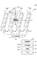
- FIG. 1 is a diagram showing a power supply device 100 of the embodiment.
- the power feeding device 100 includes an array antenna 110, a phase shifter 120, a microwave source 130, a camera 140, and a control device 150.
- the plane view is an XY plane view.
- the X-axis is an example of the first axis
- the Y-axis is an example of the second axis
- the Z-axis is an example of the third axis.
- the XY plane is an example of the first plane
- the XZ plane is an example of the second plane.
- the array antenna 110 is grouped into four sub-arrays 110A, 110B, 110C, and 110D as an example.
- the sub-arrays 110A to 110D are arranged in the X-axis direction, and each sub-array 110A to 110D includes four antenna elements 111 as an example. Therefore, the array antenna 110 includes 16 antenna elements 111 as an example.
- the antenna element 111 is a patch antenna having a rectangular shape in a plan view.
- the array antenna 110 may have a ground plate held at the ground potential on the ⁇ Z direction side of the antenna element 111. As an example, the center of the position of the 16 antenna elements 111 coincides with the origin of the XYZ coordinate system.
- phase shifters 120 are provided corresponding to the four sub-arrays 110A to 110D, and the four phase shifters 120 are connected to the antenna elements 111 of the sub-arrays 110A to 110D, respectively.
- the four antenna elements 111 are connected in parallel to one phase shifter 120.
- the phase shifter 120 is an example of a phase adjusting unit.
- each of the sub-arrays 110A to 110D power of the same phase is supplied to the four antenna elements 111. Further, the phases of the electric power output by the four phase shifters 120 to the sub-arrays 110A to 110D are different from each other. Therefore, the angle (elevation angle) of the beam formed by the radio waves radiated from the 16 antenna elements 111 can be controlled in the XZ plane. Further, the beam has a directivity of a narrow angle, and the directivity is, for example, about 5 degrees to about 15 degrees.
- the beam formed by the radio waves radiated from the 16 antenna elements 111 is synonymous with the beam output by the array antenna 110. Further, the beam output by the array antenna 110 is synonymous with the beam output by the power feeding device 100.
- the microwave generation source 130 is connected to four phase shifters 120 and supplies microwaves of a predetermined power.
- the microwave generation source 130 is an example of a radio wave generation source.
- the microwave frequency is, for example, 915 MHz.
- the mode in which the power feeding device 100 includes the microwave generation source 130 will be described here, the power feeding device 100 is not limited to microwaves, and may be radio waves having a predetermined frequency.
- the camera 140 is arranged between the sub-arrays 110B and 110C.
- the camera 140 has a fisheye lens 141 and a camera body 142.
- the camera 140 is an example of an image acquisition unit.
- the fisheye lens 141 is a lens that employs an equidistant projection method.
- the position of the center of the fisheye lens 141 coincides with the center of the 16 antenna elements 111 and the origin of the XYZ coordinate system.
- the camera body 142 may be a part of the camera 140 other than the fisheye lens 141, and may be a camera capable of receiving infrared rays having a predetermined wavelength.
- the predetermined wavelength is 850 nm as an example, but it may be a wavelength other than 850 nm.
- the camera 140 capable of receiving infrared rays of 850 nm is, for example, an infrared camera equipped with a filter capable of receiving infrared rays of 850 nm, or a CMOS (Complementary Metal Oxide Semiconductor) provided with a filter capable of receiving infrared rays and transmitting a wavelength of 850 nm. Image sensor etc.
- CMOS Complementary Metal Oxide Semiconductor
- the camera 140 acquires an image including a marker through the fisheye lens 141 and outputs the image data to the control device 150.
- the marker is attached to the target to which the beam output by the power feeding device 100 is to be irradiated.
- the power feeding device 100 obtains the position of the marker included in the image acquired by the camera 140, and irradiates the beam toward the target.
- the control device 150 includes a position conversion unit 151, an elevation angle acquisition unit 152, a control unit 153, and a memory 154.
- the control device 150 is realized by a computer including a CPU (Central Processing Unit) and a memory.
- the position conversion unit 151, the elevation angle acquisition unit 152, and the control unit 153 show the function of the program executed by the control device 150 as a functional block.
- the memory 154 functionally represents the memory of the control device 150.
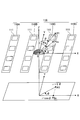
- FIG. 2 is a diagram showing a polar coordinate system of the array antenna 110.
- FIG. 2 shows only the array antenna 110 and the camera 140 of the power feeding device 100. Further, FIG. 2 shows a polar coordinate system on a plane parallel to the XY plane.
- the position of the marker in the XYZ coordinate system is P1
- the elevation angle of the line segment connecting the origin O and the position P1 is ⁇
- the azimuth angle is ⁇ .
- the elevation angle is an angle with respect to the + Z direction
- the azimuth is an angle with respect to the + X direction
- counterclockwise is a positive value in a plan view.
- the elevation angle of the line segment connecting the position P1a projected on the XZ plane and the origin O is defined as ⁇ a.
- Position P1 is an example of the first position, and position P1a is an example of the projection position.
- the origin O is an example of a reference point in the XYZ coordinate system.
- the power feeding device 100 controls the elevation angle of the beam output by the array antenna 110 only in the XZ plane. This assumes that the position of the target does not deviate much from the XZ plane (for example, the elevation angle with respect to the Z axis in the YZ plane is within ⁇ 30 degrees). This is because if the target is in such a position, the target can be irradiated with the beam simply by controlling the elevation angle of the beam in the XZ plane.
- the position conversion unit 151 performs image processing on the image acquired by the camera 140, and converts the equidistant projection image obtained through the fisheye lens 141 into polar coordinates on a plane parallel to the XY plane. By this image processing, the position P1 of the marker included in the image acquired by the camera 140 with respect to the array antenna 110 is converted to the position P2 in polar coordinates on the XY plane.
- the position P2 is an example of the second position.
- the position P2 is represented by a radius r from the origin O and an argument ⁇ .
- the declination ⁇ is the same as the azimuth angle ⁇ .
- the position conversion unit 151 obtains r ⁇ cos ⁇ that maps the radius r on the X axis by the above-mentioned image processing.
- the elevation angle acquisition unit 152 uses the value (r ⁇ cos ⁇ / f L ) obtained by dividing the X coordinate (r ⁇ cos ⁇ ) of the mapping position P2a, which is the mapping of the position P2 on the X axis, by the focal length f L of the fisheye lens 141 as the elevation angle ⁇ a. Get (calculate). The reason why the elevation angle ⁇ a can be obtained in this way will be described later.
- the control unit 153 controls the phase shifter 120 so that the direction of the beam emitted by the array antenna 110 is the elevation angle ⁇ a in the XZ plane.
- the elevation angle ⁇ a is acquired by the elevation angle acquisition unit 152.
- the control unit 153 controls the output of the microwave generation source 130, controls the shooting of the camera 140, and the like.
- the memory 154 is acquired by the position conversion unit 151, the elevation angle acquisition unit 152, the program executed when the control unit 153 performs processing, the data used in the execution of the program, the data generated by the execution of the program, and the camera 140. Stores image data, etc.
- the elevation angle ⁇ a can be obtained by the following equation (1) from the geometrical relationship between the position P1 and the position P1a by using the azimuth angle ⁇ and the elevation angle ⁇ .
- Equation (2) when the elevation angle ⁇ is sufficiently small, tan ⁇ , when the azimuth angle ⁇ is sufficiently small, cos ⁇ 1, and when the azimuth angle ⁇ is close to 90 degrees, cos ⁇ 0. Therefore, the equation (2) can be transformed into the following equation (3).
- the elevation angle ⁇ a can be approximated as in Eq. (3).
- the radius r is expressed by the following equation (4).
- r f L ⁇ (4)
- the elevation angle ⁇ a can be expressed by the following equation (5).
- ⁇ a r ⁇ cos ⁇ / f L (5) In this way, the elevation angle ⁇ a can be approximately obtained by using the equation (5).
- the position P1 obtained by equal-distance projection is converted into polar coordinates on a plane parallel to the XY plane to change the position P2.
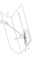
- FIG. 3 is a diagram showing an application example of the power feeding device 100.
- the power feeding device 100 is mounted on the vehicle 30 as an example, and an antenna 20 as a target is provided on the inner wall 10 of the tunnel.
- a marker 50 is connected to the antenna 20.
- the marker 50 includes a reflector that reflects infrared rays by retroreflection (retroreflection).
- the vehicle 30 is an example of the first object
- the inner wall 10 of the tunnel is an example of the second object.
- the vehicle 30 and the inner wall 10 of the tunnel move relatively, so that the vehicle 30 and the marker 50 also move relatively.
- the relative movement direction of the marker 50 with respect to the power feeding device 100 mounted on the vehicle 30 is the ⁇ X direction.
- the camera 140 converts the position of the marker 50 into polar coordinates on a plane parallel to the XY plane, and further maps the X of the mapping position (the mapping position corresponding to P2a) on the X axis.
- an antenna 20, a sensor that monitors looseness of bolts, etc., a rectenna, and a capacitor are attached to a fixing portion that fixes an infrastructure structure such as a jet fan or a sign attached to the inner wall 10 of a tunnel to the inner wall 10.
- the wireless communication module is provided, and when the beam is radiated from the power feeding device 100 to the antenna 20 while traveling in the vehicle 30, the rectenna connected to the antenna 20 converts the microwave into electric power.
- the power converted by the rectenna is stored in the capacitor, activating the marker and sensor and wireless communication module.
- the marker performs a predetermined operation
- the wireless communication module transmits a signal representing the output of the sensor, and the signal is received on the vehicle 30 side, so that the fixed state of the infrastructure structure can be inspected while traveling.
- a sensor that monitors the looseness of bolts or the like in the fixed portion is incorporated in a washer and fastened together with the bolts to detect the looseness of the bolts. The predetermined operation of the marker will be described later.
- the X coordinate (r ⁇ cos ⁇ ) of the mapping position (the mapping position corresponding to P2a) mapped to the X axis is obtained from the position of the antenna 20 deviated from the XZ plane, and the X coordinate (r ⁇ cos ⁇ ) is the focus of the fisheye lens 141. Since the beam is controlled using the value divided by the distance f L (r ⁇ cos ⁇ / f L ) as the elevation angle ⁇ a, when the vehicle 30 traveling in the X-axis direction shifts to either plus or minus of the Y-axis. However, the elevation angle ⁇ a can be obtained by absorbing the positional deviation.
- FIG. 4 is a diagram showing a marker 50.
- the marker 50 includes a housing 51, a reflector 52, LEDs 53 (53A to 53G), and a control unit 54.
- the housing 51 is a cylindrical case. Two reflectors 52 and a plurality of LEDs 53 (53A to 53G) are exposed on the outer peripheral surface of the housing 51. Further, a control unit 54 is provided inside the housing 51.
- such a marker 50 is attached to a predetermined position on the inner wall 10 of the tunnel (see FIG. 3).
- the predetermined position is, for example, a predetermined position in a cross section obtained by cutting a tunnel in a plane perpendicular to the traveling direction, and is a predetermined height position on the left side of the inner wall 10 facing the traveling direction. .. If the markers 50 are attached to such positions along the tunnel at regular intervals, the markers 50 will repeatedly appear diagonally upward to the left and forward in the traveling direction of the vehicle 30 when the vehicle 30 travels in the tunnel.
- the reflector 52 is a reflector that reflects infrared rays by retroreflection (retroreflective), and is provided on the upper side and the lower side of the outer peripheral surface of the housing 51.
- the reflector 52 is a retroreflector (retroreflector) that reflects incident infrared rays along the incident direction, and for example, a film-like reflector or a reflector-type reflector can be used.
- the direction in which the reflector 52 reflects is substantially equal to the incident direction of infrared rays.
- a plurality of LEDs 53 are provided along the circumferential direction between the upper reflector 52 and the lower reflector 52 on the outer peripheral surface of the housing 51, and output infrared rays having a wavelength of 850 nm. It is an infrared LED.
- the LED 53 is an example of the second infrared output unit, and the infrared rays output by the LEDs 53 (53A to 53G) are an example of the second infrared rays.
- the plurality of LEDs 53 are, as an example, a half-circumferential portion not located on the inner wall 10 side of the tunnel (the portion visible in FIG. 4). ) May be provided. That is, as shown in FIG. 4, the plurality of LEDs 53 are provided on the outer peripheral surface of the front half circumference, and seven LEDs 53A to 53G are shown as an example.
- LED53 when LEDs 53A to 53G are not particularly distinguished, they are simply referred to as LED53.
- the LED 53 has directivity to output infrared rays at a narrow angle.
- the directivity of the LED 53 is, for example, about 10 degrees to about 20 degrees.
- the lighting of each LED 53 is controlled by the control unit 54.
- the LEDs 53A to 53G are arranged in the order of the LED 53A located on the leftmost side and the LED53G located on the rightmost side.
- the control unit 54 is activated by the electric power received by the antenna 20 and stored in the capacitor, and lights the LEDs 53A to 53G one by one by using the electric power stored in the capacitor.
- the order of lighting is the order of LEDs 53A to 53G. This means that when the vehicle 30 approaches the marker 50, the LEDs 53A are turned on in order so that the infrared rays output by each LED 53 are irradiated to the camera 140 of the power feeding device 100 mounted on the vehicle 30. Because.
- each LED 53 may be provided with a rectenna in the direction of its directivity so that the LED 53 connected to the rectenna irradiated with microwaves is turned on.
- the LED 56 at the optimum position lights up in sequence according to the relative angular displacement of the vehicle 30 and the marker 50. Therefore, it is necessary to perform special control for setting the directivity direction of the LED 53. Since there is no such thing, the design can be simplified.
- FIG. 5 is a diagram showing an operation example in the power supply system 200.
- FIG. 5 shows a state in which the positional relationship between the power supply system 200 and the marker 50 is viewed from the right side in the moving direction of the vehicle 30. Therefore, in FIG. 5, the right direction is the + X direction.
- the markers 50 (A) and 50 (B) indicate the markers 50 at the positions (A) and (B) relative to the vehicle 30, respectively.
- the relative movement direction of the marker 50 is the ⁇ X direction.
- the power supply system 200 includes a power supply device 100 and a marker 50.
- the marker 50 is fixed to the inner wall 10 of the tunnel, and the power feeding device 100 is mounted on the vehicle 30.
- the power feeding device 100 further includes an infrared output unit 160 in addition to the components shown in FIGS. 1 and 2.
- the infrared output unit 160 is, for example, an infrared projector that outputs infrared rays having a wavelength of 850 nm.
- the infrared output unit 160 is provided in the vicinity of the array antenna 110, and has a directivity of about 10 degrees to about 20 degrees as an example.
- the directivity of the infrared output unit 160 is an example of the first directivity, and the infrared output unit 160 irradiates the irradiation range 160A with infrared rays.
- the irradiation range 160A is obtained by the directivity of the infrared output unit 160, and faces diagonally upward to the left and forward where the marker 50 appears in the tunnel as the vehicle 30 advances.
- the direction in which the irradiation range 160A faces is the direction in which the marker 50 appears when the vehicle 30 travels in the tunnel.
- FIG. 5 shows the beams 115A (115A1, 115A2) output from the array antenna 110.
- the directivity of the beams 115A (115A1, 115A2) is from about 5 degrees to about 15 degrees.
- the beam 115A of the array antenna 110 can be directed to the position indicated as the beam 115A1 or the direction indicated as the beam 115A2.
- the infrared output unit 160 irradiates the irradiation range 160A with infrared rays and the marker 50 at the position (A) enters the irradiation range 160A
- the reflector 52 of the marker 50 recurs. Infrared rays are reflected in the incident direction by reflection.
- the camera 140 receives the reflected light
- the position conversion unit 151 performs image processing and conversion to polar coordinates
- the elevation angle acquisition unit 152 acquires the elevation angle ⁇ a corresponding to the position (A)
- the control unit 153 Controls the phase shifter 120, and the array antenna 110 outputs a beam in the direction of the elevation angle ⁇ a.
- the beam 115A1 is output to the marker 50 at the position (A), and the antenna 20 in the vicinity of the marker 50 receives electric power.
- the vehicle 30 is moving, and the position of the marker 50 with respect to the vehicle 30 is relatively moving from the position (A) to the position (B).
- the marker 50 outputs infrared rays from the LED 53A at a position (B) relative to the vehicle 30.
- the LED 53A is used when the vehicle 30 travels in a tunnel at a predetermined speed, the antenna 20 receives power at the position (A), and then the LED 53A outputs infrared rays at the position (B). It has a directivity to output infrared rays in a direction in which infrared rays can be received from the LED 53A.
- the position conversion unit 151 performs image processing and conversion to polar coordinates
- the elevation angle acquisition unit 152 has an elevation angle corresponding to the position (B).
- the control unit 153 controls the phase shifter 120, and the array antenna 110 outputs a beam in the direction of the elevation angle ⁇ a.
- the beam 115A2 is output to the marker 50 at the position (B), and the antenna 20 in the vicinity of the marker 50 receives electric power.
- the marker 50 sequentially outputs infrared rays to the LEDs 53B to 53G by using the electric power stored in the capacitor.
- the power feeding device 100 receives infrared rays from the LEDs 53B to 53G, the power feeding device 100 identifies the position of the marker 50 and outputs the beam 115A toward the marker 50.
- the directivity direction of the LED 53B is shifted by the angle between the position (A) and the position (B) seen from the power feeding device 100 with respect to the directivity direction of the LED 53A.
- the LED 53C The directivity direction of the to 53G is sequentially shifted by the angle between the position (A) and the position (B) with respect to the directivity direction of the LED 53B.
- the directivity of the sandwich angle of the LEDs 53A to 53G is set so as to be narrow so that the infrared irradiation ranges of the LEDs 53A to 53G do not overlap within the range of the distance where the vehicle 30 is located with respect to the marker 50. ing.
- the output of the beam 115A by the power feeding device 100 and the output of infrared rays from the LED 53 by the marker 50 are such that the power feeding device 100 outputs the beam 115A in response to the reception of infrared rays from the LED 53G, and the power feeding device 100 outputs the beam 115A. This is performed until the infrared rays from the LED 53 are no longer received.
- FIG. 6 is a diagram showing a process executed by the control unit 153 of the power feeding device 100. The process shown in FIG. 6 shows the process of the power feeding method of the embodiment.
- control unit 153 When the process starts, the control unit 153 outputs infrared rays from the infrared output unit 160 (step S1).
- the control unit 153 determines whether or not infrared rays have been received from the marker 50 (step S2).
- the infrared rays received from the marker 50 by the power feeding device 100 are the reflected light of the infrared rays output from the infrared output unit 160 for the first time (first time), and the infrared rays output by the LED 53 of the marker 50 for the second and subsequent times.
- control unit 153 determines that it has received infrared rays (S2: YES), it causes the array antenna 110 to output the beam 115A (step S3). More specifically, the position conversion unit 151 performs image processing and conversion to polar coordinates, the elevation angle acquisition unit 152 acquires the elevation angle ⁇ a corresponding to the position (B), and the control unit 153 controls the phase shifter 120. , The array antenna 110 outputs a beam in the direction of the elevation angle ⁇ a.
- step S3 When the process of step S3 is completed, the control unit 153 returns the flow to step S2.
- control unit 153 determines in step S2 that it has not received infrared rays (S2: NO), it ends a series of processes (end).
- the processing ends, for example, when the power feeding device 100 outputs the beam 115A when the power feeding device 100 receives the infrared rays from the LED 53G and the power feeding device 100 does not receive the infrared rays from the LED 53, and when the power feeding device 100 does not receive the infrared rays from the LED 53, other than the marker 50. This is the case when infrared rays reflected by an object are received.
- FIG. 7 is a diagram showing an operation when the power feeding device 100 receives infrared rays reflected by an object 60 other than the marker 50.
- the objects 60 (A) and 60 (B) indicate the objects 60 at the positions (A) and (B) relative to the vehicle 30, respectively.
- the vehicle 30 advances while the infrared output unit 160 irradiates the irradiation range 160A with infrared rays, the object 60 at the position (A) enters the irradiation range 160A, and the infrared rays reflected by the object 60 are captured by the camera. It is assumed that the light is received by 140.
- the object 60 is an object other than the marker 50, and is an object facing the vehicle 30 at the position (A) or a retroreflector provided on the inner wall 10 of the tunnel.
- the camera 140 receives the reflected light
- the position conversion unit 151 performs image processing and conversion to polar coordinates
- the elevation angle acquisition unit 152 acquires the elevation angle ⁇ a corresponding to the position (A)
- the control unit 153 Controls the phase shifter 120, and the array antenna 110 outputs a beam in the direction of the elevation angle ⁇ a.
- the beam 115A1 is output toward the object 60 at the position (A).
- the vehicle 30 is moving, and the position of the marker 50 with respect to the vehicle 30 is relatively moving from the position (A) to the position (B).
- the power feeding device 100 Infrared rays are not received from the object 60 at position (B).
- step S1 the power supply device 100 ends the process.
- step S2 the flowchart shown in FIG. 6, it is determined that infrared rays are irradiated in step S1, YES in step S2, beam 115A is output in step S3, and NO is determined in the returned step S2, and the process is completed.
- the power feeding device 100 accidentally receives the reflected infrared light from the object 60 other than the marker 50, the process is completed only by outputting the beam 115A once. As a result, the unnecessary output of the beam 115A is suppressed.
- FIG. 8 is a diagram showing another operation example in the power supply system 200.
- the markers 50 (A), 50 (B), and 50 (C) indicate the markers 50 at the positions (A), (B), and (C) relative to the vehicle 30, respectively.
- the power feeding device 100 outputs the beam 115A2 to the marker 50 at the position (B), and the antenna 20 in the vicinity of the marker 50 receives electric power.
- control unit 54 of the marker 50 determines that the power received by the antenna 20 has reached a predetermined amount or more, the control unit 54 lights the LED 53 without lighting the LED 53B. End the process.
- the control unit 54 determines that the wireless communication module has sufficient power to transmit the detected data, it receives more power. Since it is not necessary to do so, the lighting control of the LED 53 is terminated. When the lighting control of the LED 53 is finished, the power feeding device 100 stops outputting the beam 115A.
- the marker 50 does not light the LED 53. Therefore, when the marker 50 is in the position (C), the power feeding device 100 does not output the beam 115A.
- the control unit 54 of the marker 50 ends the lighting process of the LED 53 when the power received by the antenna 20 and the electric power stored in the capacitor exceeds a predetermined amount, the beam 115A is more than necessary. And infrared output is not required.
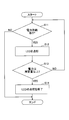
- FIG. 9 is a flowchart showing a process executed by the control unit 54 of the marker 50.
- control unit 54 determines whether or not there is power supply from the capacitor (step S11).
- step S12 When the control unit 54 determines that there is power supply (S11: YES), the control unit 54 turns on the LED 53 (step S12). Each time the flow shown in FIG. 9 is repeatedly executed, the LEDs 53A to 53G are turned on one by one in order in step S12.
- the control unit 54 determines whether or not the electric power stored in the capacitor is equal to or greater than a predetermined amount (step S13).
- control unit 54 determines that the electric power is equal to or greater than a predetermined amount (S13: YES)
- the control unit 54 ends the lighting of the LED 53 (step S14).
- control unit 54 finishes the process of step S14, the control unit 54 ends a series of processes (end).
- control unit 54 determines in step S13 that the electric power is not equal to or greater than the predetermined amount (S13: NO)
- the control unit 54 returns the flow to step S11.
- control unit 54 ends a series of processes (end) even when it is determined in step S11 that there is no power supply (S11: YES).
- the control unit 54 controls that the marker 50 does not light the LED 53 at the position (C) as shown in FIG. 8, and the power feeding device 100 outputs the beam 115A. Will not be.
- the markers 50 are in the positions (A) and (B), after the processing of returning to YES in step S11, step S12, and NO in step S13 to step S11 is performed, the marker 50 is performed.
- it is determined as YES in step S13, which corresponds to turning off the LED 53 in step S14.
- the power feeding device 100 when the power feeding device 100 receives infrared rays (reflected light or infrared rays of LED 53), it outputs a beam 115A in the direction of arrival of infrared rays.
- the power feeding device 100 receives the infrared rays again, and outputs the beam 115A each time the infrared rays are received.
- the wireless communication module emits a signal representing the output of the sensor and receives it on the vehicle 30 side, so that the fixed state of the infrastructure structure can be inspected while traveling.
- infrared rays come from an object 60 other than the marker 50, the object 60 does not receive the beam 115A, so that the process ends there.
- whether or not the power feeding device 100 outputs the beam 115A from the second time onward depends on whether the object that reflects the infrared rays first output by the infrared output unit 160 is the marker 50 or the object 60 other than the marker 50. It is determined by the fact that the marker 50 or not is not particularly identified.
- the beam 115A can be output to the marker 50 to supply power with a very simple configuration.
- the marker 50 including the LEDs 53 (53A to 53G) having the directivity of the narrow angle power is continuously supplied only to the marker 50 without distinguishing whether the reflection source is the marker 50 or not. Is possible.
- the marker 50 is a passive type that does not have a power supply and is driven by the electric power stored in the capacitor by the antenna 20 receiving the beam, a cable or a battery for supplying the electric power is unnecessary. , Low running cost and excellent maintainability.
- the marker 50 has a reflector 52 that reflects infrared rays by retroreflective (retroreflective), infrared rays can be reflected toward the infrared output unit 160 of the power feeding device 100. Then, the power feeding device 100 outputs the beam 115A in the direction of the elevation angle ⁇ a indicating the direction in which the marker 50, which is the reflection source of infrared rays, exists, and the antenna 2 arranged in the vicinity of the marker 50 receives the beam 115A. Therefore, it is possible to reliably supply electric power to the relatively moving marker 50, and it is possible to provide a highly reliable power supply system 200.
- the power feeding device 100 controls the elevation angle of the beam output by the array antenna 110 only in the XZ plane, the number of phase shifters 120 is larger than that in the case where the elevation angle is controlled in both the XZ plane and the YZ plane. Only a quarter is needed. Therefore, the power feeding device 100 can be realized at low cost.
- the form in which the marker 50 lights the LEDs 53A to 53G each time power is supplied from the power feeding device 100 to the marker 50 via the antenna 20 has been described.
- the wireless communication module transmits the detection data detected by each sensor in order, how much power the beam 115A by one output has. May be determined according to the number of sensors, the number of sensors operating on the beam 115A with one output, the capacity of the capacitor, and the like.
- the vehicle 30 and the marker 50 may move so as to pass each other. Passing each other means that when the vehicle 30 and the marker 50 are moving in opposite directions, they are misaligned.
- the center of the fisheye lens 141 coincides with the center of the 16 antenna elements 111 has been described.
- the center of the fisheye lens 141 may be deviated from the center of the 16 antenna elements 111.
- the coordinate origin of the array antenna control phase calculation may be shifted by the amount of the positional deviation.
- the wireless communication module is not limited to the one provided on the inner wall 10 of the tunnel. , It may be installed in various places. In this way, the power feeding device 100 can be used as a communication device.
Landscapes
- Engineering & Computer Science (AREA)
- Computer Networks & Wireless Communication (AREA)
- Power Engineering (AREA)
- Physics & Mathematics (AREA)
- Optics & Photonics (AREA)
- Variable-Direction Aerials And Aerial Arrays (AREA)
- Support Of Aerials (AREA)
Abstract
簡易な構成で無線給電を可能とする給電システム、給電装置、及び、給電方法を提供する。 給電システムは、第1物体に設けられ、前記第1物体と相対的に移動する第2物体が出現する第1方向に第1赤外線を出力する第1指向性を有し、前記第1赤外線を出力する第1赤外線出力部と、前記第2物体に設けられ、再帰反射で第1赤外線を反射する反射体と、前記第2物体に設けられ、相対的に移動する前記第1物体が存在する第2方向に第2赤外線を出力する第2指向性を有し、無線給電によって受電した電力で前記第2赤外線を出力する第2赤外線出力部と、前記第1物体に設けられ、前記第1赤外線の前記反射体による反射赤外線、又は、前記第2赤外線を受光すると、前記反射赤外線、又は、前記第2赤外線の到来方向にビームを出力する、給電部とを含む。
Description
本発明は、給電システム、給電装置、及び、給電方法に関する。
従来の非接触電力伝送システムでは、車両は、送電装置に対する位置合わせ時に、発光装置を点滅させるとともに、点滅周期情報を送電装置に送信する。そして、送電装置において、制御装置は、たとえば、撮像装置によって撮影された撮影画像に従って発光装置の点滅周期を認識し、通信装置によって受信された点滅周期情報が示す点滅周期と、撮影画像に従って認識された点滅周期とが同一である場合には、撮像装置によって撮影された車両を、撮影画像から認識された点滅周期を示す点滅周期情報を送信した車両と対応付ける(例えば、特許文献1参照)。
従来の非接触電力伝送システムは、通信装置によって受信された点滅周期情報が示す点滅周期と、撮影画像に従って認識された点滅周期とが同一であるかどうかの判定を行うため、構成が複雑であった。
そこで、簡易な構成で無線給電を可能とする給電システム、給電装置、及び、給電方法を提供することを目的とする。
本発明の実施の形態の給電システムは、第1物体に設けられ、前記第1物体と相対的に移動する第2物体が出現する第1方向に第1赤外線を出力する第1指向性を有し、前記第1赤外線を出力する第1赤外線出力部と、前記第2物体に設けられ、再帰反射で第1赤外線を反射する反射体と、前記第2物体に設けられ、相対的に移動する前記第1物体が存在する第2方向に第2赤外線を出力する第2指向性を有し、無線給電によって受電した電力で前記第2赤外線を出力する第2赤外線出力部と、前記第1物体に設けられ、前記第1赤外線の前記反射体による反射赤外線、又は、前記第2赤外線を受光すると、前記反射赤外線、又は、前記第2赤外線の到来方向にビームを出力する、給電部とを含む。
簡易な構成で無線給電を可能とする給電システム、給電装置、及び、給電方法を提供することができる。
以下、本発明の給電システム、給電装置、及び、給電方法を適用した実施の形態について説明する。
<実施の形態>
実施の形態の給電システム及び給電方法について説明する前に、図1及び図2を用いて、実施の形態の給電装置100について説明する。
実施の形態の給電システム及び給電方法について説明する前に、図1及び図2を用いて、実施の形態の給電装置100について説明する。
図1は、実施の形態の給電装置100を示す図である。給電装置100は、アレイアンテナ110、フェーズシフタ120、マイクロ波発生源130、カメラ140、及び制御装置150を含む。
以下では、XYZ座標系を用いて説明する。平面視とはXY平面視のことである。また、X軸は第1軸の一例であり、Y軸は第2軸の一例であり、Z軸は第3軸の一例である。また、XY平面は第1平面の一例であり、XZ平面は第2平面の一例である。
アレイアンテナ110は、一例として4つのサブアレイ110A、110B、110C、110Dにグループ分けされている。サブアレイ110A~110Dは、X軸方向に配列されており、各サブアレイ110A~110Dは、一例として4つのアンテナ素子111を含む。このため、アレイアンテナ110は、一例として16個のアンテナ素子111を含む。アンテナ素子111は、平面視で矩形状のパッチアンテナである。アレイアンテナ110は、アンテナ素子111の-Z方向側にグランド電位に保持されるグランド板を有していてもよい。なお、一例として、16個のアンテナ素子111の位置の中心は、XYZ座標系の原点と一致している。
フェーズシフタ120は、4つのサブアレイ110A~110Dに対応して4つ設けられており、4つのフェーズシフタ120は、それぞれサブアレイ110A~110Dのアンテナ素子111に接続されている。各サブアレイ110A~110Dの中では、4つのアンテナ素子111は、1つのフェーズシフタ120に並列に接続されている。フェーズシフタ120は、位相調節部の一例である。
各サブアレイ110A~110Dの中では、4つのアンテナ素子111には同一の位相の電力が供給される。また、4つのフェーズシフタ120がサブアレイ110A~110Dに出力する電力の位相は互いに異なる。このため、16個のアンテナ素子111から放射される電波が形成するビームの角度(仰角)をXZ平面内で制御することができる。また、ビームは、挟角の指向性を有し、指向性は、一例として、約5度から約15度である。
16個のアンテナ素子111から放射される電波が形成するビームは、アレイアンテナ110が出力するビームと同義である。また、アレイアンテナ110が出力するビームは、給電装置100が出力するビームと同義である。
マイクロ波発生源130は、4つのフェーズシフタ120に接続されており、所定の電力のマイクロ波を供給する。マイクロ波発生源130は、電波発生源の一例である。マイクロ波の周波数は、一例として915MHzである。なお、ここでは給電装置100がマイクロ波発生源130を含む形態について説明するが、マイクロ波に限られるものではなく、所定の周波数の電波であればよい。
カメラ140は、サブアレイ110Bと110Cの間に配置される。カメラ140は、魚眼レンズ141及びカメラ本体142を有する。カメラ140は、画像取得部の一例である。
魚眼レンズ141は、等距離射影方式を採用したレンズである。魚眼レンズ141の中心の位置は、一例として、16個のアンテナ素子111の中心及びXYZ座標系の原点と一致している。カメラ本体142は、カメラ140のうち魚眼レンズ141以外の部分であり、所定の波長の赤外線を受光できるカメラであればよい。所定の波長は、一例として、850nmであるが、850nm以外の波長であってもよい。
850nmの赤外線を受光可能なカメラ140は、例えば、850nmの波長を透過するフィルタを備えた赤外線カメラ、又は、赤外線を受光可能で850nmの波長を透過するフィルタを備えたCMOS(Complementary Metal Oxide Semiconductor)イメージセンサ等である。
カメラ140は、魚眼レンズ141を通じてマーカを含む画像を取得し、画像データを制御装置150に出力する。マーカは、給電装置100が出力するビームを照射したいターゲットに取り付けられている。給電装置100は、カメラ140で取得した画像に含まれるマーカの位置を求め、ターゲットに向けてビームを照射する。
制御装置150は、位置変換部151、仰角取得部152、制御部153、及びメモリ154を有する。制御装置150は、CPU(Central Processing Unit)及びメモリを含むコンピュータによって実現される。位置変換部151、仰角取得部152、制御部153は、制御装置150が実行するプログラムの機能(ファンクション)を機能ブロックとして示したものである。また、メモリ154は、制御装置150のメモリを機能的に表したものである。
ここで、位置変換部151、仰角取得部152、制御部153、メモリ154については、図1に加えて図2を用いて説明する。図2は、アレイアンテナ110の極座標系を示す図である。図2には、給電装置100のうちのアレイアンテナ110とカメラ140のみを示す。また、図2には、XY平面に平行な平面上における極座標系を示す。
また、XYZ座標系におけるマーカの位置をP1とし、原点Oと位置P1を結ぶ線分の仰角をθ、方位角をφとする。仰角は+Z方向に対する角度であり、方位角は+X方向に対する角度であり、平面視で反時計回りを正の値とする。また、位置P1をXZ平面に投影した位置P1aと原点Oとを結ぶ線分の仰角をθaとする。
位置P1は、第1位置の一例であり、位置P1aは、投影位置の一例である。また、原点OはXYZ座標系の基準点の一例である。
給電装置100は、アレイアンテナ110が出力するビームの仰角をXZ平面内でのみ制御する。これは、ターゲットの位置がXZ平面からあまりずれていない(例えば、YZ平面内でのZ軸に対する仰角で±30度以内程度)ことを想定している。このような位置にあるターゲットであれば、ビームの仰角をXZ平面内で制御するだけで、ターゲットにビームを照射できるからである。
位置変換部151は、カメラ140が取得した画像に対して画像処理を行い、魚眼レンズ141を通じて得た等距離射影の画像をXY平面に平行な平面上における極座標に変換する。この画像処理により、カメラ140によって取得される画像に含まれるマーカのアレイアンテナ110に対する位置P1は、XY平面上の極座標における位置P2に変換される。位置P2は、第2位置の一例である。
位置P2は、原点Oからの動径rと偏角φによって表される。動径rは、魚眼レンズ141の焦点距離をfLとすると、r=fLθで表される。偏角φは方位角φと同一である。位置変換部151は、上述の画像処理によって、動径rをX軸に写像したr・cosφを求める。
仰角取得部152は、位置P2をX軸に写像した写像位置P2aのX座標(r・cosφ)を魚眼レンズ141の焦点距離fLで除算した値(r・cosφ/fL)を、仰角θaとして取得(計算)する。このようにして仰角θaを取得できる理由については後述する。
制御部153は、アレイアンテナ110が放射するビームの方向がXZ平面内で仰角θaになるようにフェーズシフタ120を制御する。仰角θaは、仰角取得部152によって取得される。また、制御部153は、マイクロ波発生源130の出力制御、及び、カメラ140の撮影制御等を行う。
メモリ154は、位置変換部151、仰角取得部152、制御部153が処理を行う際に実行するプログラム、プログラムの実行に伴い利用するデータ、プログラムの実行によって生じるデータ、及び、カメラ140が取得する画像データ等を格納する。
次に、仰角θaを求める方法について説明する。
仰角θaは、方位角φと仰角θを用いると、位置P1と位置P1aの幾何学的関係から次式(1)で求めることができる。


また、上述したように、魚眼レンズ141の焦点距離をfLとすると、動径rは次式(4)で表される。
r=fLθ (4)
式(3)、(4)より、仰角θaは次式(5)で表すことができる。
θa=r・cosφ/fL (5)
このように、式(5)を用いて、仰角θaを近似的に求めることができる。
r=fLθ (4)
式(3)、(4)より、仰角θaは次式(5)で表すことができる。
θa=r・cosφ/fL (5)
このように、式(5)を用いて、仰角θaを近似的に求めることができる。
以上のように、アレイアンテナ110のビームの仰角をXZ平面内でのみ制御する場合には、等距離射影によって得られた位置P1をXY平面に平行な平面上における極座標に変換して位置P2を求め、さらに位置P2をX軸に写像した写像位置P2aのX座標(r・cosφ)を魚眼レンズ141の焦点距離fLで除算することで、仰角θa(=r・cosφ/fL)を求めることができる。
図3は、給電装置100の適用例を示す図である。給電装置100は、一例として車両30に搭載されており、トンネルの内壁10にはターゲットとしてのアンテナ20が設けられている。アンテナ20にはマーカ50が接続されている。マーカ50は、再帰反射(再帰性反射)で赤外線を反射する反射体を含む。ここで、車両30は、第1物体の一例であり、トンネルの内壁10は、第2物体の一例である。車両30が+X方向に進行すると、車両30とトンネルの内壁10とは相対的に移動するため、車両30とマーカ50も相対的に移動することになる。車両30に搭載された給電装置100に対するマーカ50の相対移動方向は、-X方向である。ここでは、車両30がマーカ50を相対的に追い越すように移動する形態について説明する。ここでは、マーカ50が停止している場合について説明するが、追い越すとは、相手が停止している場合、又は、同一方向に進行している場合に、相手を後ろから抜いて先に行くことである。
車両30が+X方向に走行する際に、カメラ140でマーカ50の位置をXY平面に平行な平面上における極座標に変換し、さらにX軸に写像した写像位置(P2aに相当する写像位置)のX座標(r・cosφ)を魚眼レンズ141の焦点距離fLで除算して求まる仰角θa(=r・cosφ/fL)を用いて、アンテナ20にビームを照射することができる。
例えば、トンネルの内壁10に取り付けてあるジェットファンや標識等のインフラ構造物を内壁10に固定する固定部に、アンテナ20と、固定部のボルト等の緩みを監視するセンサと、レクテナと、キャパシタと、無線通信モジュールとを設けておき、車両30で走行しながら給電装置100からアンテナ20にビームを放射すると、アンテナ20に接続されたレクテナがマイクロ波を電力に変換する。レクテナによって変換された電力は、キャパシタに蓄積され、マーカとセンサおよび無線通信モジュールを起動する。そして、マーカが所定の動作を行い、無線通信モジュールがセンサの出力を表す信号を送信し、車両30側で受信することにより、走行しながらインフラ構造物の固定状態を検査することができる。なお、固定部のボルト等の緩みを監視するセンサは、一例として、ワッシャに組み込まれてボルトとともに締結され、ボルトの緩みを検出する。なお、マーカの所定の動作については後述する。
また、XZ平面からずれたアンテナ20の位置からX軸に写像した写像位置(P2aに相当する写像位置)のX座標(r・cosφ)を求め、X座標(r・cosφ)を魚眼レンズ141の焦点距離fLで除算した値(r・cosφ/fL)を仰角θaとして使用してビームを制御するので、X軸方向に走行する車両30がY軸のプラスマイナスのどちらかにシフトとしている場合でも、その位置ずれを吸収して仰角θaを求めることができる。
ここで、図4を用いてマーカ50の詳細について説明する。図4は、マーカ50を示す図である。マーカ50は、筐体51、反射体52、LED53(53A~53G)、及び制御部54を含む。筐体51は、円筒状のケースである。筐体51の外周面には、2つの反射体52と、複数のLED53(53A~53G)が露出している。また、筐体51の内部には、制御部54が設けられている。
このようなマーカ50は、一例として、トンネルの内壁10(図3参照)の予め決められた位置に取り付けられる。予め決められた位置とは、一例として、トンネルを進行方向に垂直な平面で切断して得る断面における所定の位置であり、進行方向を向いて内壁10の左側の所定の高さの位置である。トンネルに沿ってこのような位置に一定間隔でマーカ50を取り付ければ、車両30でトンネルを走行する場合に、車両30の進行方向における左斜め上前方に繰り返しマーカ50が出現することになる。
反射体52は、再帰反射(再帰性反射)で赤外線を反射する反射体であり、筐体51の外周面の上側と下側に設けられている。反射体52は、入射する赤外線を入射方向に沿って反射する再帰反射体(再帰性反射体)であり、例えば、フィルム状、又は、反射板型のものを用いることができる。反射体52が反射する方向は、赤外線の入射方向に略等しい。
LED53(53A~53G)は、筐体51の外周面で、上側の反射体52と下側の反射体52との間で周方向に沿って複数設けられており、波長が850nmの赤外線を出力する赤外線LEDである。LED53は、第2赤外線出力部の一例であり、LED53(53A~53G)が出力する赤外線は、第2赤外線の一例である。
マーカ50は、一例として、トンネルの内壁10(図3参照)に取り付けるので、複数のLED53(53A~53G)は、一例として、トンネルの内壁10側に位置しない半周の部分(図4で見える部分)にわたって設けられていればよい。すなわち、複数のLED53は、図4に示すように、手前側の半周分の外周面に設けられており、一例として、7つのLED53A~53Gを示す。以下では、LED53A~53Gを特に区別しない場合には、単にLED53と称す。
LED53は、赤外線を挟角で出力する指向性を有する。LED53の指向性は、一例として、約10度から約20度である。各LED53の点灯は、制御部54によって制御される。LED53A~53Gは、向かって一番左側に位置するLED53Aから、向かって一番右側に位置するLED53Gの順に配列されている。
制御部54は、アンテナ20で受電され、キャパシタに蓄積される電力で起動し、キャパシタに蓄積された電力を利用してLED53A~53Gを1つずつ順番に点灯させる。点灯させる順番は、LED53A~53Gの順である。これは、車両30がマーカ50に近づいてくるときに、LED53Aから順番に点灯させることによって、各LED53が出力する赤外線が車両30に搭載された給電装置100のカメラ140に照射されるようにするためである。
なお、LED53毎にその指向性の方向にレクテナを具備することによって、マイクロ波が照射されているレクテナに接続されているLED53が点灯するようにしてもよい。車両30の移動に伴い、車両30とマーカ50の相対的な角度変位に応じて最適な位置にあるLED56が順次点灯していくため、LED53の指向性の方向の設定について特段の制御を行う必要はないことから設計の簡易化が図れる。
次に、給電装置100を含む給電システム200について説明する。図5は、給電システム200における動作例を示す図である。図5では、給電システム200とマーカ50との位置関係を車両30の移動方向における右側から見た状態を示す。このため、図5では、右方向が+X方向である。また、マーカ50(A)、50(B)は、それぞれ、車両30に対する相対的な位置(A)、(B)におけるマーカ50を示す。マーカ50の相対移動方向は、-X方向である。
給電システム200は、給電装置100と、マーカ50とを含む。マーカ50は、トンネルの内壁10に固定されており、給電装置100は、車両30に搭載されている。給電装置100は、図1及び図2に示す構成要素に加えて、さらに赤外線出力部160を含む。
赤外線出力部160は、一例として、波長が850nmの赤外線を出力する赤外線投光器である。赤外線出力部160は、アレイアンテナ110の近傍に設けられており、一例として、約10度から約20度の指向性を有する。赤外線出力部160の指向性は、第1指向性の一例であり、赤外線出力部160は、照射範囲160Aに赤外線を照射する。照射範囲160Aは、赤外線出力部160の指向性によって得られるものであり、車両30の進行に伴って、トンネル内でマーカ50が出現する左斜め上前方を向いている。照射範囲160Aが向く方向は、車両30がトンネル内を進行した場合に、マーカ50が出現する方向である。
また、図5には、アレイアンテナ110から出力されるビーム115A(115A1、115A2)を示す。ビーム115A(115A1、115A2)の指向性は、約5度から約15度である。アレイアンテナ110のビーム115Aは、ビーム115A1として示す位置や、ビーム115A2として示す方向に向けることができる。
図5に示すように、赤外線出力部160が照射範囲160Aに赤外線を照射しながら車両30が進行し、照射範囲160Aに位置(A)のマーカ50が入ると、マーカ50の反射体52が再帰反射によって赤外線を入射方向に反射する。
給電装置100は、カメラ140で反射光を受光し、位置変換部151が画像処理や極座標への変換を行い、仰角取得部152が位置(A)に相当する仰角θaを取得し、制御部153がフェーズシフタ120を制御して、アレイアンテナ110が仰角θaの方向にビームを出力する。これにより、位置(A)のマーカ50にビーム115A1が出力され、マーカ50の近傍のアンテナ20が電力を受電する。
車両30は進行しており、車両30に対するマーカ50の位置は、位置(A)から位置(B)に相対的に移動している。マーカ50は、車両30との相対的な位置(B)において、LED53Aから赤外線を出力する。LED53Aは、車両30が予め決められた速度でトンネル内を走行する場合に、位置(A)でアンテナ20が受電してから、位置(B)でLED53Aが赤外線を出力した場合に、車両30がLED53Aから赤外線を受光できる方向に赤外線を出力する指向性を有する。
給電装置100のカメラ140が位置(B)においてLED53Aから出力された赤外線を受光すると、位置変換部151が画像処理や極座標への変換を行い、仰角取得部152が位置(B)に相当する仰角θaを取得し、制御部153がフェーズシフタ120を制御して、アレイアンテナ110が仰角θaの方向にビームを出力する。これにより、位置(B)のマーカ50にビーム115A2が出力され、マーカ50の近傍のアンテナ20が電力を受電する。
その後は、車両30がさらに進行し、アンテナ20が受電する度に、キャパシタに蓄積された電力を利用して、マーカ50はLED53B~53Gに赤外線を順次出力させる。給電装置100がLED53B~53Gからの赤外線を受光すると、給電装置100は、マーカ50の位置を特定し、マーカ50に向けてビーム115Aを出力する。
LED53Bの指向性の向きは、LED53Aの指向性の向きに対して、給電装置100から見た位置(A)と位置(B)との間の角度の分だけずらされており、同様に、LED53C~53Gの指向性の向きは、LED53Bの指向性の向きに対して、位置(A)と位置(B)との間の角度の分だけ順次ずらされている。
また、LED53A~53Gの挟角の指向性は、マーカ50に対して車両30が位置する距離の範囲内で、LED53A~53Gの各々の赤外線の照射範囲が重ならない程度に狭くなるように設定されている。
このような給電装置100によるビーム115Aの出力と、マーカ50によるLED53からの赤外線の出力とは、給電装置100がLED53Gからの赤外線を受光したことに対してビーム115Aを出力し、給電装置100がLED53からの赤外線を受光しなくなるまで行われる。
図6は、給電装置100の制御部153が実行する処理を示す図である。図6に示す処理は、実施の形態の給電方法の処理を示す。
制御部153は、処理がスタートすると、赤外線出力部160から赤外線を出力する(ステップS1)。
制御部153は、マーカ50から赤外線を受光したかどうかを判定する(ステップS2)。給電装置100がマーカ50から受光する赤外線は、最初(1回目)は赤外線出力部160から出力された赤外線の反射光であり、2回目以降は、マーカ50のLED53が出力した赤外線である。
制御部153は、赤外線を受光した(S2:YES)と判定すると、アレイアンテナ110にビーム115Aを出力させる(ステップS3)。より具体的には、位置変換部151が画像処理や極座標への変換を行い、仰角取得部152が位置(B)に相当する仰角θaを取得し、制御部153がフェーズシフタ120を制御して、アレイアンテナ110が仰角θaの方向にビームを出力する。
ステップS3の処理が終了すると、制御部153はフローをステップS2にリターンさせる。
制御部153は、ステップS2において、赤外線を受光していない(S2:NO)と判定すると、一連の処理を終了する(エンド)。処理が終了するのは、例えば、給電装置100がLED53Gからの赤外線を受光したことに対してビーム115Aを出力し、給電装置100がLED53からの赤外線を受光しなかった場合と、マーカ50以外の物体で反射された赤外線を受光した場合である。
図7は、マーカ50以外の物体60で反射された赤外線を給電装置100が受光する場合の動作を示す図である。図6において、物体60(A)、60(B)は、それぞれ、車両30に対する相対的な位置(A)、(B)における物体60を示す。
図7に示すように、赤外線出力部160が照射範囲160Aに赤外線を照射しながら車両30が進行し、照射範囲160Aに位置(A)の物体60が入り、物体60で反射された赤外線がカメラ140によって受光されたとする。物体60は、マーカ50以外の物体であり、位置(A)において車両30の方を向いていた物体や、トンネルの内壁10に設けられた再帰反射体である。
給電装置100は、カメラ140で反射光を受光し、位置変換部151が画像処理や極座標への変換を行い、仰角取得部152が位置(A)に相当する仰角θaを取得し、制御部153がフェーズシフタ120を制御して、アレイアンテナ110が仰角θaの方向にビームを出力する。これにより、位置(A)の物体60に向けてビーム115A1が出力される。
車両30は進行しており、車両30に対するマーカ50の位置は、位置(A)から位置(B)に相対的に移動している。
しかしながら、物体60は、アンテナ20のように受電可能な構成要素には接続されておらず、アンテナ20のように受電可能な構成要素を含まず、LED53を有していないため、給電装置100が位置(B)の物体60から赤外線を受信することはない。
この結果、給電装置100は処理を終了する。これは、図6に示すフローチャートにおいて、ステップS1で赤外線を照射、ステップS2でYES、ステップS3でビーム115Aを出力、リターンしたステップS2でNOと判定して処理が終了するパターンである。
このため、給電装置100がマーカ50以外の物体60から偶然的に赤外線の反射光を受光した場合には、ビーム115Aを一度出力するだけで処理が終了することになる。この結果、無駄にビーム115Aを出力することが抑制される。
図8は、給電システム200における他の動作例を示す図である。マーカ50(A)、50(B)、50(C)は、それぞれ、車両30に対する相対的な位置(A)、(B)、(C)におけるマーカ50を示す。
図8において、位置(A)から位置(B)までは、図5に示す動作と同一である。図8では、位置(B)よりも後の位置(C)における動作が図5とは異なる。
給電装置100が位置(B)のマーカ50にビーム115A2を出力し、マーカ50の近傍のアンテナ20が電力を受電する。
このときに、マーカ50の制御部54が、アンテナ20で受電され、キャパシタに蓄積された電力が所定量以上になったと判定すると、制御部54は、LED53Bの点灯を行わずに、LED53の点灯処理を終了する。
例えば、固定部のボルト等の緩みを監視するセンサが検出を行い、検出データを無線通信モジュールが送信するのに十分な電力があると制御部54が判定した場合には、それ以上電力を受電しなくてもよいため、LED53の点灯制御を終了する。LED53の点灯制御を終了すれば、給電装置100は、ビーム115Aを出力しなくなる。
この結果、位置(C)では、マーカ50は、LED53の点灯を行わない。このため、マーカ50が位置(C)にあるときには、給電装置100は、ビーム115Aを出力しない。
このように、マーカ50の制御部54が、アンテナ20によって受電され、キャパシタに蓄積された電力が所定量以上になった場合にLED53の点灯処理を終了するようにすれば、必要以上にビーム115Aや赤外線の出力を行わずに済む。
図9は、マーカ50の制御部54が実行する処理を示すフローチャートである。
制御部54は、処理がスタートすると、キャパシタからの電力供給があるかどうかを判定する(ステップS11)。
制御部54は、電力供給がある(S11:YES)と判定すると、LED53を点灯する(ステップS12)。図9に示すフローが繰り返し実行される度に、ステップS12では、LED53A~53Gが、1つずつ順番に点灯される。
制御部54は、キャパシタに蓄積されている電力が所定量以上であるかどうかを判定する(ステップS13)。
制御部54は、電力が所定量以上である(S13:YES)と判定すると、LED53の点灯を終了する(ステップS14)。
制御部54は、ステップS14の処理を終えると、一連の処理を終了する(エンド)。
また、制御部54は、ステップS13において、電力が所定量以上ではない(S13:NO)と判定すると、フローをステップS11にリターンする。
また、制御部54は、ステップS11において、電力供給がない(S11:YES)と判定した場合にも、一連の処理を終了する(エンド)。
制御部54が図9に示すような処理を行うことにより、図8に示すように、位置(C)では、マーカ50はLED53を点灯しなくなる制御が行われ、給電装置100はビーム115Aを出力しなくなる。これは、図9において、マーカ50が位置(A)及び(B)にいるときに、ステップS11でYES、ステップS12、ステップS13でNOでステップS11にリターンする処理が行われた後に、マーカ50が位置(C)に相対的に移動すると、ステップS13でYESと判定し、ステップS14でLED53を点灯しなくなることに相当する。
以上のように、給電装置100は、赤外線(反射光又はLED53の赤外線)を受光すると、赤外線の到来方向に向けてビーム115Aを出力する。赤外線がマーカ50から到来した場合には、給電装置100は、再び赤外線を受信することになり、赤外線を受信する度にビーム115Aを出力することになる。この結果、無線通信モジュールがセンサの出力を表す信号を放射し、車両30側で受信することにより、走行しながらインフラ構造物の固定状態を検査することができる。また、赤外線がマーカ50以外の物体60から到来した場合には、物体60はビーム115Aを受電しないので、そこで処理を終える。
このように、給電装置100が二回目以降にビーム115Aを出力するかどうかは、最初に赤外線出力部160が出力した赤外線を反射する物体が、マーカ50であるかマーカ50以外の物体60であるかによって決まり、マーカ50であるかどうかを特に識別しているわけではない。
このため、非常に簡単な構成でマーカ50に対してビーム115Aを出力して給電を行うことができる。
したがって、簡易な構成で無線給電を可能とする給電システム200、給電装置100、及び、給電方法を提供することができる。
また、挟角の指向性を有するLED53(53A~53G)を含むマーカ50を用いることにより、反射源がマーカ50であるかどうかを識別することなく、マーカ50にのみ継続的に給電を行うことが可能になっている。
また、マーカ50は、電源を持たずに、アンテナ20がビームを受信することによってキャパシタに蓄えられた電力で駆動するパッシブタイプであるため、電力を供給するためのケーブルやバッテリ等が不要であり、ランニングコストが低く、メインテナンス性に優れている。
また、マーカ50は、再帰反射(再帰性反射)で赤外線を反射する反射体52を有するので、給電装置100の赤外線出力部160に向けて赤外線を反射できる。そして、給電装置100は、赤外線の反射源であるマーカ50が存在する方向を表す仰角θaの方向にビーム115Aを出力し、マーカ50の近傍に配置されたアンテナ2がビーム115Aを受電する。このため、相対的に移動するマーカ50に確実に電力を供給することができ、信頼性の高い給電システム200を提供できる。
また、給電装置100は、アレイアンテナ110が出力するビームの仰角をXZ平面内でのみ制御するため、仰角をXZ平面内とYZ平面内の両方で制御する場合に比べてフェーズシフタ120の数が4分の1で済む。このため、給電装置100を安価に実現することができる。
なお、以上では、給電装置100からアンテナ20を介してマーカ50に電力が供給される度に、マーカ50がLED53A~53Gを点灯させる形態について説明した。1つのアンテナ20から複数のセンサに電力が供給されて、各センサが検出した検出データを順番に無線通信モジュールが送信する場合に、1回の出力によるビーム115Aがどの程度の電力量を有するかは、センサの数、1回の出力によるビーム115Aで動作するセンサの数、キャパシタの容量等に応じて決定すればよい。
また、以上では、車両30がマーカ50を相対的に追い越すように移動する形態について説明したが、車両30とマーカ50がすれ違うように移動する形態であってもよい。すれ違うとは、車両30とマーカ50が互いに反対方向に移動しているときに、入れ違いになることである。
また、以上では、魚眼レンズ141の中心が16個のアンテナ素子111の中心と一致している形態について説明した。しかしながら、魚眼レンズ141の中心は、16個のアンテナ素子111の中心からずれていてもよい。この場合には、位置ずれの分だけアレイアンテナ制御位相計算の座標原点をずらせばよい。
また、ここでは図3を用いて給電装置100がトンネルの内壁10に設けられた無線通信モジュールと通信する形態について説明したが、無線通信モジュールはトンネルの内壁10に設けられているものに限らず、様々な場所等に設置されていてよい。このようにすれば、給電装置100を通信装置として利用することができる。
以上、本発明の例示的な実施の形態の給電システム、給電装置、及び、給電方法について説明したが、本発明は、具体的に開示された実施の形態に限定されるものではなく、特許請求の範囲から逸脱することなく、種々の変形や変更が可能である。
なお、本国際出願は、2020年2月27日に出願した日本国特許出願2020-031361号に基づく優先権を主張するものであり、その全内容は本国際出願にここでの参照により援用されるものとする。
50 マーカ
52 反射体
53、53A~53 GLED
100 給電装置
110 アレイアンテナ
110A~110D サブアレイ
111 アンテナ素子
120 フェーズシフタ
130 マイクロ波発生源
140 カメラ
141 魚眼レンズ
150 制御装置
151 位置変換部
152 仰角取得部
153 制御部
160 赤外線出力部
52 反射体
53、53A~53 GLED
100 給電装置
110 アレイアンテナ
110A~110D サブアレイ
111 アンテナ素子
120 フェーズシフタ
130 マイクロ波発生源
140 カメラ
141 魚眼レンズ
150 制御装置
151 位置変換部
152 仰角取得部
153 制御部
160 赤外線出力部
Claims (7)
- 第1物体に設けられ、前記第1物体と相対的に移動する第2物体が出現する第1方向に第1赤外線を出力する第1指向性を有し、前記第1赤外線を出力する第1赤外線出力部と、
前記第2物体に設けられ、再帰反射で第1赤外線を反射する反射体と、
前記第2物体に設けられ、相対的に移動する前記第1物体が存在する第2方向に第2赤外線を出力する第2指向性を有し、無線給電によって受電した電力で前記第2赤外線を出力する第2赤外線出力部と、
前記第1物体に設けられ、前記第1赤外線の前記反射体による反射赤外線、又は、前記第2赤外線を受光すると、前記反射赤外線、又は、前記第2赤外線の到来方向にビームを出力する、給電部と
を含む、給電システム。 - 前記第2物体に設けられ、前記無線給電による受電量が所定の受電量以上になると、前記第2赤外線出力部に前記第2赤外線の出力を停止させる、出力制御部をさらに含む、請求項1記載の給電システム。
- 前記第2赤外線出力部は、相対的に移動する前記第1物体の時系列的に変化する複数の位置に向けて互いに異なる前記第2指向性を有する複数の赤外線出力部を有する、請求項1又は2記載の給電システム。
- 前記第1物体と前記第2物体は、相対的に移動して追い越す、又は、相対的に移動してすれ違う、請求項1乃至3のいずれか一項記載の給電システム。
- 前記給電部は、
第1軸及び第2軸に沿って二次元的に配置される複数のアンテナ素子を有するアレイアンテナと、
電波発生源と、
前記アレイアンテナと前記電波発生源との間に設けられ、前記電波発生源から前記複数のアンテナ素子に供給される電力の位相を前記第1軸方向において調節する位相調節部と、
魚眼レンズを通じて画像を取得する画像取得部と、
前記画像取得部によって取得される画像に含まれるマーカの前記画像取得部に対する第1位置を、前記第1軸及び前記第2軸を含む第1平面上の極座標における第2位置に変換する位置変換部と、
前記第2位置に基づいて、前記第1位置を前記第1軸と第3軸とを含む第2平面に投影した投影位置の前記第2平面内での前記第3軸に対する仰角を求める仰角取得部と、
前記アレイアンテナが放射するビームの方向が前記第2平面内で前記仰角になるように前記位相調節部を制御する制御部と
を有する、請求項1乃至4のいずれか一項記載の給電システム。 - 第1物体に設けられ、前記第1物体と相対的に移動する第2物体が出現する第1方向に第1赤外線を出力する第1指向性を有し、前記第1赤外線を出力する第1赤外線出力部と、
前記第1物体に設けられる給電部であって、前記第2物体に設けられ再帰反射で第1赤外線を反射する反射体による反射赤外線、又は、前記第2物体に設けられ相対的に移動する前記第1物体が存在する第2方向に第2赤外線を出力する第2指向性を有する第2赤外線出力部が無線給電によって受電した電力で出力した前記第2赤外線を受光すると、前記反射赤外線、又は、前記第2赤外線の到来方向にビームを出力する、給電部と
を含む、給電装置。 - 第1物体に設けられ、前記第1物体と相対的に移動する第2物体が出現する第1方向に第1赤外線を出力する第1指向性を有し、前記第1赤外線を出力する第1赤外線出力部と、
前記第2物体に設けられ、再帰反射で第1赤外線を反射する反射体と、
前記第2物体に設けられ、相対的に移動する前記第1物体が存在する第2方向に第2赤外線を出力する第2指向性を有し、無線給電によって受電した電力で前記第2赤外線を出力する第2赤外線出力部と
を含む給電システムにおける給電方法であって、
前記第1赤外線の前記反射体による反射赤外線、又は、前記第2赤外線を前記第1物体側で受光すると、前記反射赤外線、又は、前記第2赤外線の到来方向にビームを出力する、給電方法。
Priority Applications (3)
| Application Number | Priority Date | Filing Date | Title |
|---|---|---|---|
| CN202180016781.1A CN115136452A (zh) | 2020-02-27 | 2021-01-06 | 供电系统、供电装置及供电方法 |
| EP21761119.3A EP4084285A4 (en) | 2020-02-27 | 2021-01-06 | POWER SUPPLY SYSTEM, POWER SUPPLY DEVICE AND POWER SUPPLY METHOD |
| US17/759,395 US12095286B2 (en) | 2020-02-27 | 2021-01-06 | Power supply system, power supply device, and power supply method |
Applications Claiming Priority (2)
| Application Number | Priority Date | Filing Date | Title |
|---|---|---|---|
| JP2020-031361 | 2020-02-27 | ||
| JP2020031361A JP7069232B2 (ja) | 2020-02-27 | 2020-02-27 | 給電システム、給電装置、及び、給電方法 |
Publications (1)
| Publication Number | Publication Date |
|---|---|
| WO2021171790A1 true WO2021171790A1 (ja) | 2021-09-02 |
Family
ID=77491405
Family Applications (1)
| Application Number | Title | Priority Date | Filing Date |
|---|---|---|---|
| PCT/JP2021/000213 Ceased WO2021171790A1 (ja) | 2020-02-27 | 2021-01-06 | 給電システム、給電装置、及び、給電方法 |
Country Status (5)
| Country | Link |
|---|---|
| US (1) | US12095286B2 (ja) |
| EP (1) | EP4084285A4 (ja) |
| JP (1) | JP7069232B2 (ja) |
| CN (1) | CN115136452A (ja) |
| WO (1) | WO2021171790A1 (ja) |
Families Citing this family (4)
| Publication number | Priority date | Publication date | Assignee | Title |
|---|---|---|---|---|
| JP6795637B2 (ja) * | 2019-02-20 | 2020-12-02 | ミネベアミツミ株式会社 | アンテナ装置、及び、給電装置 |
| JP7443440B1 (ja) | 2022-09-01 | 2024-03-05 | ソフトバンク株式会社 | 無線通信システム、無線通信方法、無線給電システム、及び無線給電方法 |
| US12540803B2 (en) | 2023-07-24 | 2026-02-03 | Raytheon Company | Tactical high power microwave antenna pedestal |
| WO2025215764A1 (ja) * | 2024-04-10 | 2025-10-16 | 株式会社Nttドコモ | 給電装置、受電装置、及び、給電方法 |
Citations (7)
| Publication number | Priority date | Publication date | Assignee | Title |
|---|---|---|---|---|
| JP2014079029A (ja) * | 2012-10-09 | 2014-05-01 | Nissan Motor Co Ltd | 非接触給電装置 |
| US20150311755A1 (en) * | 2012-12-05 | 2015-10-29 | Eads Deutschland Gmbh | Wireless Remote Energy Supply for Unmanned Aerial Vehicles |
| US20150318897A1 (en) * | 2008-09-30 | 2015-11-05 | Searete Llc | Beam power with receiver priority selection |
| WO2017134951A1 (ja) * | 2016-02-05 | 2017-08-10 | 株式会社東芝 | 充電装置および位置ずれ検出方法 |
| JP2018121489A (ja) | 2017-01-27 | 2018-08-02 | トヨタ自動車株式会社 | 非接触電力伝送システム |
| JP2019126198A (ja) * | 2018-01-17 | 2019-07-25 | 株式会社Nttドコモ | 給電管理サーバおよび給電システム |
| JP2020031361A (ja) | 2018-08-23 | 2020-02-27 | 株式会社Subaru | 車両の中継装置 |
Family Cites Families (1)
| Publication number | Priority date | Publication date | Assignee | Title |
|---|---|---|---|---|
| DE102004008681A1 (de) * | 2004-02-21 | 2005-09-08 | Eads Space Transportation Gmbh | Verfahren zur Energieübertragung mittels kohärenter elektromagnetischer Strahlung |
-
2020
- 2020-02-27 JP JP2020031361A patent/JP7069232B2/ja active Active
-
2021
- 2021-01-06 WO PCT/JP2021/000213 patent/WO2021171790A1/ja not_active Ceased
- 2021-01-06 EP EP21761119.3A patent/EP4084285A4/en active Pending
- 2021-01-06 US US17/759,395 patent/US12095286B2/en active Active
- 2021-01-06 CN CN202180016781.1A patent/CN115136452A/zh active Pending
Patent Citations (7)
| Publication number | Priority date | Publication date | Assignee | Title |
|---|---|---|---|---|
| US20150318897A1 (en) * | 2008-09-30 | 2015-11-05 | Searete Llc | Beam power with receiver priority selection |
| JP2014079029A (ja) * | 2012-10-09 | 2014-05-01 | Nissan Motor Co Ltd | 非接触給電装置 |
| US20150311755A1 (en) * | 2012-12-05 | 2015-10-29 | Eads Deutschland Gmbh | Wireless Remote Energy Supply for Unmanned Aerial Vehicles |
| WO2017134951A1 (ja) * | 2016-02-05 | 2017-08-10 | 株式会社東芝 | 充電装置および位置ずれ検出方法 |
| JP2018121489A (ja) | 2017-01-27 | 2018-08-02 | トヨタ自動車株式会社 | 非接触電力伝送システム |
| JP2019126198A (ja) * | 2018-01-17 | 2019-07-25 | 株式会社Nttドコモ | 給電管理サーバおよび給電システム |
| JP2020031361A (ja) | 2018-08-23 | 2020-02-27 | 株式会社Subaru | 車両の中継装置 |
Non-Patent Citations (1)
| Title |
|---|
| See also references of EP4084285A4 |
Also Published As
| Publication number | Publication date |
|---|---|
| JP2021136778A (ja) | 2021-09-13 |
| EP4084285A1 (en) | 2022-11-02 |
| US20230088273A1 (en) | 2023-03-23 |
| US12095286B2 (en) | 2024-09-17 |
| CN115136452A (zh) | 2022-09-30 |
| JP7069232B2 (ja) | 2022-05-17 |
| EP4084285A4 (en) | 2023-04-05 |
Similar Documents
| Publication | Publication Date | Title |
|---|---|---|
| JP7069232B2 (ja) | 給電システム、給電装置、及び、給電方法 | |
| JP6795637B2 (ja) | アンテナ装置、及び、給電装置 | |
| WO2022054586A1 (ja) | アンテナ装置、給電装置、及び給電方法 | |
| US11921213B2 (en) | Non-line-of-sight correction for target detection and identification in point clouds | |
| JP2009103482A (ja) | 車載用レーダ装置 | |
| JP7613740B2 (ja) | アンテナ装置、給電システム、給電装置、及び給電方法 | |
| WO2006030832A1 (ja) | 監視装置 | |
| KR101802873B1 (ko) | 타겟 추적 시스템 | |
| JPH08507366A (ja) | 空間位置決めシステム | |
| JP7740653B2 (ja) | 距離推定装置、アンテナ装置、給電システム、給電装置、及び給電方法 | |
| JPWO2018143093A1 (ja) | 計測装置 | |
| JP2003332838A (ja) | マルチビームアンテナ装置 | |
| JP7708415B2 (ja) | 距離推定装置、アンテナ装置、給電システム、給電装置、及び給電方法 | |
| WO2007074443A2 (en) | Millimeter wave imaging system | |
| JP7445628B2 (ja) | 位置情報導出システム | |
| JP2002243853A (ja) | レーダ光軸調整装置 | |
| JP7264749B2 (ja) | ステレオカメラ、及びステレオカメラ一体型ライトユニット | |
| CN108370091A (zh) | 天线以及包括这种天线的防碰撞检测系统 | |
| JP2023183133A (ja) | アンテナ装置、給電装置、及び給電方法 | |
| JPH054061U (ja) | 送受信装置 | |
| CN116027354A (zh) | 识别高反射率物体的方法及系统 |
Legal Events
| Date | Code | Title | Description |
|---|---|---|---|
| 121 | Ep: the epo has been informed by wipo that ep was designated in this application |
Ref document number: 21761119 Country of ref document: EP Kind code of ref document: A1 |
|
| ENP | Entry into the national phase |
Ref document number: 2021761119 Country of ref document: EP Effective date: 20220728 |
|
| NENP | Non-entry into the national phase |
Ref country code: DE |