WO2021177242A1 - クロマトグラフおよび試料分析方法 - Google Patents
クロマトグラフおよび試料分析方法 Download PDFInfo
- Publication number
- WO2021177242A1 WO2021177242A1 PCT/JP2021/007745 JP2021007745W WO2021177242A1 WO 2021177242 A1 WO2021177242 A1 WO 2021177242A1 JP 2021007745 W JP2021007745 W JP 2021007745W WO 2021177242 A1 WO2021177242 A1 WO 2021177242A1
- Authority
- WO
- WIPO (PCT)
- Prior art keywords
- switching valve
- flow path
- fluid
- column
- detector
- Prior art date
- Legal status (The legal status is an assumption and is not a legal conclusion. Google has not performed a legal analysis and makes no representation as to the accuracy of the status listed.)
- Ceased
Links
Images









Classifications
-
- G—PHYSICS
- G01—MEASURING; TESTING
- G01N—INVESTIGATING OR ANALYSING MATERIALS BY DETERMINING THEIR CHEMICAL OR PHYSICAL PROPERTIES
- G01N30/00—Investigating or analysing materials by separation into components using adsorption, absorption or similar phenomena or using ion-exchange, e.g. chromatography or field flow fractionation
- G01N30/02—Column chromatography
- G01N30/26—Conditioning of the fluid carrier; Flow patterns
- G01N30/28—Control of physical parameters of the fluid carrier
- G01N30/32—Control of physical parameters of the fluid carrier of pressure or speed
-
- G—PHYSICS
- G01—MEASURING; TESTING
- G01N—INVESTIGATING OR ANALYSING MATERIALS BY DETERMINING THEIR CHEMICAL OR PHYSICAL PROPERTIES
- G01N30/00—Investigating or analysing materials by separation into components using adsorption, absorption or similar phenomena or using ion-exchange, e.g. chromatography or field flow fractionation
- G01N30/02—Column chromatography
- G01N30/26—Conditioning of the fluid carrier; Flow patterns
- G01N30/38—Flow patterns
- G01N30/44—Flow patterns using recycling of the fraction to be distributed
-
- G—PHYSICS
- G01—MEASURING; TESTING
- G01N—INVESTIGATING OR ANALYSING MATERIALS BY DETERMINING THEIR CHEMICAL OR PHYSICAL PROPERTIES
- G01N30/00—Investigating or analysing materials by separation into components using adsorption, absorption or similar phenomena or using ion-exchange, e.g. chromatography or field flow fractionation
- G01N30/02—Column chromatography
- G01N30/26—Conditioning of the fluid carrier; Flow patterns
-
- G—PHYSICS
- G01—MEASURING; TESTING
- G01N—INVESTIGATING OR ANALYSING MATERIALS BY DETERMINING THEIR CHEMICAL OR PHYSICAL PROPERTIES
- G01N30/00—Investigating or analysing materials by separation into components using adsorption, absorption or similar phenomena or using ion-exchange, e.g. chromatography or field flow fractionation
- G01N30/02—Column chromatography
- G01N30/26—Conditioning of the fluid carrier; Flow patterns
- G01N30/38—Flow patterns
-
- G—PHYSICS
- G01—MEASURING; TESTING
- G01N—INVESTIGATING OR ANALYSING MATERIALS BY DETERMINING THEIR CHEMICAL OR PHYSICAL PROPERTIES
- G01N30/00—Investigating or analysing materials by separation into components using adsorption, absorption or similar phenomena or using ion-exchange, e.g. chromatography or field flow fractionation
- G01N30/02—Column chromatography
- G01N2030/022—Column chromatography characterised by the kind of separation mechanism
- G01N2030/027—Liquid chromatography
-
- G—PHYSICS
- G01—MEASURING; TESTING
- G01N—INVESTIGATING OR ANALYSING MATERIALS BY DETERMINING THEIR CHEMICAL OR PHYSICAL PROPERTIES
- G01N30/00—Investigating or analysing materials by separation into components using adsorption, absorption or similar phenomena or using ion-exchange, e.g. chromatography or field flow fractionation
- G01N30/02—Column chromatography
- G01N30/26—Conditioning of the fluid carrier; Flow patterns
- G01N30/28—Control of physical parameters of the fluid carrier
- G01N30/32—Control of physical parameters of the fluid carrier of pressure or speed
- G01N2030/326—Control of physical parameters of the fluid carrier of pressure or speed pumps
-
- G—PHYSICS
- G01—MEASURING; TESTING
- G01N—INVESTIGATING OR ANALYSING MATERIALS BY DETERMINING THEIR CHEMICAL OR PHYSICAL PROPERTIES
- G01N30/00—Investigating or analysing materials by separation into components using adsorption, absorption or similar phenomena or using ion-exchange, e.g. chromatography or field flow fractionation
- G01N30/02—Column chromatography
- G01N30/26—Conditioning of the fluid carrier; Flow patterns
- G01N30/38—Flow patterns
- G01N2030/382—Flow patterns flow switching in a single column
- G01N2030/385—Flow patterns flow switching in a single column by switching valves
-
- G—PHYSICS
- G01—MEASURING; TESTING
- G01N—INVESTIGATING OR ANALYSING MATERIALS BY DETERMINING THEIR CHEMICAL OR PHYSICAL PROPERTIES
- G01N30/00—Investigating or analysing materials by separation into components using adsorption, absorption or similar phenomena or using ion-exchange, e.g. chromatography or field flow fractionation
- G01N30/02—Column chromatography
- G01N30/04—Preparation or injection of sample to be analysed
- G01N30/16—Injection
- G01N30/20—Injection using a sampling valve
-
- G—PHYSICS
- G01—MEASURING; TESTING
- G01N—INVESTIGATING OR ANALYSING MATERIALS BY DETERMINING THEIR CHEMICAL OR PHYSICAL PROPERTIES
- G01N30/00—Investigating or analysing materials by separation into components using adsorption, absorption or similar phenomena or using ion-exchange, e.g. chromatography or field flow fractionation
- G01N30/02—Column chromatography
- G01N30/26—Conditioning of the fluid carrier; Flow patterns
- G01N30/38—Flow patterns
- G01N30/46—Flow patterns using more than one column
Definitions
- the present invention relates to a chromatograph and a sample analysis method.
- a chromatograph is known as a sample analyzer for analyzing the components of a sample.
- the chromatograph is an analytical method in which a mobile phase medium is pressurized by a pump or the like and passed through a column, and the species to be analyzed are separated and detected with high performance by utilizing the difference in interaction between the stationary phase and the mobile phase.
- a gas chromatograph or the like using a gas called a carrier gas as a mobile phase medium is used.
- a liquid chromatograph or the like using a liquid called an eluent as a mobile phase medium is used.
- the length of the column which is the stationary phase is lengthened to lengthen the elution time of each component, or multiple columns are arranged in series in the flow path. It is conceivable that However, if the length of the column is increased or if a plurality of columns are arranged in series, the column itself becomes large. Further, as the length of the column is increased, it is necessary to increase the delivery pressure when the sample and the mobile phase medium are delivered to the column, so that the pump becomes larger. That is, the sample analysis system using the chromatograph becomes large and costly.
- Patent Document 1 Japanese Unexamined Patent Publication No. 2006-201039 uses high performance liquid chromatography (HPLC: HPLC:) in which a recycling separation method is adopted. High Performance Liquid Chromatography) is disclosed. In this method, the liquid sample once passed through the HPLC column and the eluent are circulated together and passed through the same HPLC column multiple times to artificially lengthen the length of the HPLC column and improve the separation resolution. It is a method of increasing.
- the liquid feeding pressure is equivalent to that of one HPLC column, and an HPLC column of multiple HPLC columns or multiple times the length can be obtained.
- the same separation resolution as when used can be obtained.
- Patent Document 2 Japanese Unexamined Patent Publication No. 2010-249588
- Patent Document 2 Japanese Unexamined Patent Publication No. 2010-249588
- a buffer portion for holding the liquid sample and the eluent is provided in the closed flow path so that the first eluted component does not flow into the column until the last eluted component is eluted from the column. prepare.
- Patent Document 2 Japanese Unexamined Patent Publication No. 2010-249588
- the circulation for recycling separation is performed three times, and each component separated by the column is detected at the fourth time, thereby virtually.
- the column is fed with the total amount of liquid sample and eluent required for the final separation on the column each time. That is, in the first, second, and third measurements, in addition to the liquid amount required for the measurement, the liquid sample and the eluent in the liquid amount not required for the measurement are sent to the column. Therefore, unnecessary measurement time is generated.
- an object of the present invention is to provide a chromatograph and a sample analysis method, which can improve the separation resolution of each component while shortening the measurement time.
- one aspect of the chromatograph according to the present invention is an interaction between a pump that delivers a fluid containing a sample that is a liquid or a gas and a stationary phase to which the fluid is supplied and held inside.
- the column that separates the components of the sample, the first buffer portion, the first switching valve, the column, the second switching valve, and the second buffer portion are interposed from one end side to the other end side.
- the pump, the first switching valve, and a control unit for controlling the second switching valve are provided.
- the control unit can switch the flow path between the first switching valve and the second switching valve in the main flow path to the bypass flow path.
- the pump, the first switching valve, and the second switching valve are controlled so that at least a part of the fluid held by the first buffer section passes through the main flow path to the second buffer section.
- the inflowing first path and the fluid held by the second buffer portion pass between the first switching valve and the second switching valve in the main flow path and pass through the bypass flow path.
- the second path that flows into the buffer section is switched.
- the first buffer section and the second buffer section are provided in the front and rear stages of the column, and the fluid containing the sample passes from the first buffer section via the first switching valve, the column, and the second switching valve.
- the first path flowing into the two buffer sections and the fluid whose components are separated by the column flow from the second buffer section around the column and flow into the first buffer section via the second switching valve and the first switching valve. It is configured so that it can be switched from the second path.
- the fluid that has passed through the column once is returned to the first buffer section, and the same column can be passed through the same column a plurality of times, so that a recycling separation method can be realized. Therefore, the separation resolution can be improved without increasing the size of the column and without increasing the pump delivery pressure.
- the fluid reciprocates between the first buffer section and the second buffer section, so that the fluid is columned N times. From the first time to the N-1 time in the case of passing through the column, the amount of fluid introduced into the column can be limited to the amount of fluid required for separation. That is, from the first time to the N-1 time, it is possible to prevent the fluid unnecessary for separation from being sent out, and the measurement time can be shortened.
- the detector may be arranged on the main flow path. In this case, each time the fluid flows in the first path, the separated components in the column can be detected. For example, if the detector is located downstream of the column in the first path, the separation component can be detected each time the fluid passes through the column. Further, since the separated component can be detected for the fluid that has passed through the column each time, for example, if a completely separated peak can be detected at a stage where the number of separations is small, the component is based on the peak. Can also be identified and quantified. Further, in the above chromatograph, the detector may be arranged between the column and the second switching valve. In this case, the separated component can be detected immediately after passing through the column. Therefore, it is possible to prevent the fluid whose components are separated in the column from being diffused before being introduced into the detector, and it is possible to improve the detection accuracy.
- the detector may be arranged outside the main flow path and the bypass flow path.
- the separated component is not detected by the detector.
- the separated component may be detected at the end. can. Since the component-separated fluid is not unnecessarily introduced into the detector, the detection accuracy can be improved.
- a discharge flow path for discharging the fluid from the downstream side of the second buffer portion in the first path is further provided, and the detector is arranged on the discharge flow path. May be good. In this case, after the recycling separation is completed, the separated component can be detected when the fluid is discharged from the downstream side of the second buffer portion.
- the chromatograph further includes a discharge flow path for discharging the fluid from between the column and the second buffer portion in the first path, and the detector is arranged on the discharge flow path. You may be. In this case, after the recycling separation is completed, the separation component can be detected when the fluid is discharged from between the column and the second buffer portion. Finally, since it does not unnecessarily pass through the second buffer portion, it is possible to suppress the diffusion of the fluid and improve the detection accuracy.
- the chromatograph further comprises a second bypass flow path bypassed the column and connected between the first switching valve and the second switching valve, and the detector is the second. It may be arranged on the bypass flow path of. In this case, the separated component can be detected by the detector at an arbitrary timing, and then the recycling separation can be restarted. For example, it is possible to determine the number of remaining recycling separations or end the recycling separation according to the detection result by the detector.
- the chromatograph further includes a sampling flow path for collecting the sample stored in the sample tank and a mobile phase medium flow path for collecting the mobile phase medium stored in the mobile phase medium tank.
- One end of the sampling flow path and one end of the mobile phase medium flow path are each connected to the first switching valve, and the pump is arranged on the upstream side of the first buffer portion in the first path.
- the control unit may control the pump and the first switching valve to switch the injection of the sample and the mobile phase medium into the first buffer unit.
- a pump for injecting the sample and the mobile phase medium into the first buffer portion and a pump for delivering the fluid containing the sample (mixture of the sample and the mobile phase medium) are realized by one pump. be able to.
- the pump can be located outside the first and second paths, fluid can be prevented from passing through the pump during recycling separation. Therefore, it is possible to prevent the fluid from being dispersed by passing through the pump, and it is possible to prevent the resolution from being lowered.
- the first buffer portion and the second buffer portion may be pipelines having a predetermined content.
- a buffer unit that holds the fluid can be configured with a simple configuration.
- the buffer portion by forming the buffer portion with a pipeline, it is possible to suppress the diffusion of the fluid in the buffer portion.
- it is preferable that the inner diameter of the pipeline is small.
- the predetermined content can be a volume equal to or larger than the amount of fluid required for separating the components in the column.
- the amount of fluid required for component separation can be appropriately supplied from the first buffer section to the column.
- the content of the second buffer section is set to a volume equal to or larger than the amount of fluid required for separating the components in the column, the fluid that has passed through the column is held in the second buffer section until all the separation in the column is completed. can do. Therefore, recycling separation can be appropriately performed.
- one aspect of the sample analysis method is the interaction between a pump that feeds a fluid containing a sample that is a liquid or a gas and a stationary phase to which the fluid is supplied and held inside.
- a column for separating the components of the above, a first buffer portion, a first switching valve, the column, a second switching valve, and a second buffer portion were interposed from one end side to the other end side.
- a chromatograph comprising a main flow path, a bypass flow path bypassing the column and connected between the first switching valve and the second switching valve, and a detector for detecting a component separated in the column.
- the sample analysis method in the graph at least a part of the liquid held by the first buffer portion is supplied to the column via the first switching valve in the main flow path, and the column in the sample.
- a separation step for separating the components of the above, and a holding step in which the fluid that has passed through the column is supplied to the second buffer section via the second switching valve in the main flow path and held in the second buffer section. Then, by controlling the first switching valve and the second switching valve, the flow path between the first switching valve and the second switching valve in the main flow path is switched to the bypass flow path, and the second switching flow path is used.
- the recovery step is repeated, the separation step is performed at least N times (N is an integer greater than 1), and then the detection step is performed by the detector.
- n (n is an integer of 1 ⁇ n ⁇ N) th separation step, n of the amount of fluid required for the column to separate the components from the first buffer section to the column for the first time. Supply twice as much of the fluid.
- the separation step By performing the separation step, the holding step, and the recovery step in this way, the fluid that has once passed through the column can be returned to the first buffer section again, and by repeating these steps, the recycling separation method can be realized. can. Therefore, the separation resolution can be improved.
- the nth separation step n times the amount of fluid required for the column to separate the components is supplied from the first buffer section to the column in the first time, so that the conventional recycling separation method is used. Unlike the case where the annular closed flow path is used as described above, it is possible to prevent the fluid unnecessary for separation from being sent out from the first time to the N-1 time. Therefore, the measurement time can be shortened.
- detection by the detector may be performed each time the separation step is performed. In this case, for example, if a completely separated peak can be detected at a stage where the number of separations is small, the components can be identified and quantified based on the peak. Further, in the detection step of the sample analysis method, the detection by the detector may be performed only after the Nth separation step. In this case, since the fluid having separated components is not unnecessarily introduced into the detector, the detection accuracy can be improved. Further, in the detection step of the sample analysis method, detection by the detector may be performed after the m (m is an integer of 1 ⁇ m ⁇ N) th separation step. That is, the separated component can be detected by the detector at an arbitrary timing until the separation is performed N times. In this case, for example, it is possible to determine the number of remaining recycling separations according to the detection result by the detector, or to end the recycling separation.
- the separation resolution of each component can be improved while shortening the measurement time.
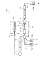
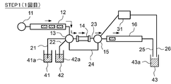
- FIG. 1 is a diagram showing a structural example of the liquid analyzer according to the first embodiment.
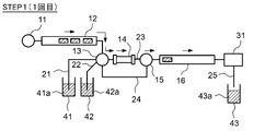
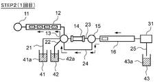
- FIG. 2A is a diagram showing an operation example of the liquid analyzer according to the first embodiment.
- FIG. 2B is a diagram showing an operation example of the liquid analyzer according to the first embodiment.
- FIG. 2C is a diagram showing an operation example of the liquid analyzer according to the first embodiment.
- FIG. 3A is a diagram showing an operation example of the liquid analyzer according to the first embodiment.
- FIG. 3B is a diagram showing an operation example of the liquid analyzer according to the first embodiment.
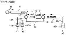
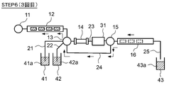
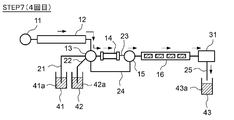
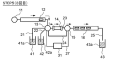
- FIG. 4A is a diagram showing an operation example of the liquid analyzer according to the first embodiment.
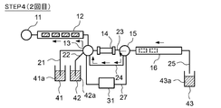
- FIG. 4B is a diagram showing an operation example of the liquid analyzer according to the first embodiment.
- FIG. 4C is a diagram showing an operation example of the liquid analyzer according to the first embodiment.
- FIG. 5 is a diagram showing a structural example of the liquid analyzer according to the second embodiment.
- FIG. 6A is a diagram showing an operation example of the liquid analyzer according to the second embodiment.
- FIG. 6B is a diagram showing an operation example of the liquid analyzer according to the second embodiment.
- FIG. 6C is a diagram showing an operation example of the liquid analyzer according to the second embodiment.
- FIG. 7 is a diagram showing an operation example of the liquid analyzer according to the second embodiment.
- FIG. 8 is a diagram showing a structural example of the liquid analyzer according to the third embodiment.
- FIG. 9A is a diagram showing an operation example of the liquid analyzer according to the third embodiment.
- FIG. 9B is a diagram showing an operation example of the liquid analyzer according to the third embodiment.
- FIG. 9C is a diagram showing an operation example of the liquid analyzer according to the third embodiment.
- FIG. 10 is a diagram showing an operation example of the liquid analyzer according to the third embodiment.
- FIG. 11 is a diagram showing a structural example of the liquid analyzer according to the fourth embodiment.
- FIG. 12A is a diagram showing an operation example of the liquid analyzer according to the fourth embodiment.
- FIG. 12B is a diagram showing an operation example of the liquid analyzer according to the fourth embodiment.
- FIG. 12C is a diagram showing an operation example of the liquid analyzer according to the fourth embodiment.
- FIG. 13A is a diagram showing an operation example of the liquid analyzer according to the fourth embodiment.
- FIG. 13B is a diagram showing an operation example of the liquid analyzer according to the fourth embodiment.
- FIG. 13C is a diagram showing an operation example of the liquid analyzer according to the fourth embodiment.
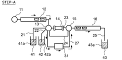
- FIG. 14A is a diagram showing a modified example of the operation of the liquid analyzer according to the fourth embodiment.
- FIG. 14B is a diagram showing an operation example of the liquid analyzer according to the fourth embodiment.
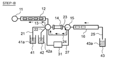
- FIG. 15A is a diagram showing a modified example of the operation of the liquid analyzer according to the fourth embodiment.
- FIG. 15B is a diagram showing an operation example of the liquid analyzer according to the fourth embodiment.
- FIG. 16 is a diagram for explaining a basic configuration example of the liquid analysis system.
- FIG. 17 is a diagram for explaining a basic configuration example of the liquid analysis system.
- FIG. 16 is a diagram for explaining a basic configuration example of the liquid analysis system.
- FIG. 18 is a diagram showing a structural example of a conventional liquid analyzer.
- FIG. 19 is an example of a signal obtained from the detector.
- FIG. 20 is a diagram showing a structural example of a conventional recycle separation type liquid analyzer.
- FIG. 21 is a diagram for explaining a problem of a conventional liquid analyzer.
- FIG. 22 is a diagram showing a structural example of the gas analyzer according to the embodiment of the present invention.
- An analysis system that employs liquid chromatography or gas chromatography is, for example, a detection system for detecting objects such as poisonous gas, explosives, and infectious diseases at an earlier stage as countermeasures against terrorism and pandemics, and the above objects. It is used as a situation grasping system based on analysis information at multiple locations for the purpose of preventing the spread of gas. It is desirable that the analyzers in these systems are small and can be installed anywhere, such as in public facilities and transportation.
- Analysis for inspection of poisonous gas and explosives can be performed by combining a collector that dissolves the gas in a liquid and liquid chromatography. It is also possible to directly analyze the poisonous gas and the explosive itself by gas chromatography.
- Examples of the above poisonous gases include sarin (C 4 H 10 FO 2 ), Soman (C 7 H 16 FO 2 P), VX gas (C 11 H 26 NO 2 PS), and mustard gas (bis (2-chloroethyl) sulfide). , C 4 H 8 C l2 S), and the explosives include TNT (trinitrotoluene) and DNT (dinitrotoluene).
- RNA or DNA of the target pathogen or virus can be directly analyzed by liquid chromatography, or sensitized by PCR, LAMP method, hybridization method, intercalator method, etc. It is also possible to analyze by liquid chromatography via the method.
- infectious diseases include charcoal flu, bird flu, Crimean-Congo hemorrhagic fever, dengue fever, Ebola hemorrhagic fever, Hendra virus infection, hepatitis, influenza, Lassa fever, Marburg fever, meningococcal disease, and nipavirus.
- Infectious diseases pesto, Rift Valley fever, severe acute respiratory syndrome (SARS), natural pox, rabbit disease, yellow fever, etc.
- the liquid analysis system includes, for example, a system for monitoring the quality of drinking water at a manufacturing factory for drinking water, and a nutrient required for plants (crop such as vegetables) dissolved in water at a plant factory. There is a system that analyzes the components of nutrient solution.
- HPLC high performance liquid chromatography
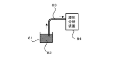
- FIG. 16 is a diagram showing an example of a liquid analysis system in a manufacturing plant for drinking water and the like.
- the liquid 82 such as the drinking water to be analyzed is charged from the liquid tank 81 for storing the drinking water or the like. Collect a part. Then, the collected liquid 82 is sent to the liquid analyzer 84 via the liquid sampling flow path 83, and the components are analyzed by the liquid analyzer 84.
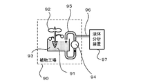
- FIG. 17 is a diagram showing an example of a liquid analysis system in a plant factory.
- nutrient solution cultivation is carried out using a nutrient solution in which nutrients necessary for plants (crops such as vegetables) are dissolved in water.
- FIG. 17 shows an example of circulation type hydroponics in which the nutrient solution 91 is circulated as the nutrient solution cultivation.
- the nutrient solution 91 supplied to the cultivation tank 93 in which the crop 92 is grown is circulated by the liquid feed pump 94 via the circulation flow path 95.
- a part of the circulating nutrient solution 91 is automatically collected, for example, through a liquid sampling flow path 96 branched from a part of the circulation flow path 95, and the collected nutrient solution 91 is a component of the liquid analyzer 97. Be analyzed.
- the composition of the nutrient solution held in the cultivation tank changes as the nutrient solution circulates. Since the growth of plants is affected by the nutrient solution components, the nutrient solution is appropriately adjusted as necessary based on the results of the nutrient solution analysis.
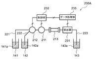
- FIG. 18 is a diagram showing a configuration example of a conventional HPLC apparatus 200A.
- the HPLC apparatus 200A includes a pump 211, a switching valve 212, and an HPLC column 213.
- the control unit 232 controls the operation of the pump 211 and the switching valve 212 to store the liquid sample 141a and the eluent in the sample tank 141 (corresponding to the liquid tank 81 in FIG. 16 and the cultivation tank 93 in FIG. 17).
- the eluent 142a stored in the tank 142 is introduced into the HPLC column 213 via the liquid sampling flow path 221 and the eluent flow path 222, respectively.
- the liquid sample 141a introduced into the HPLC column 213 is separated for each component by the HPLC column 213. Then, the separated component is detected by the detector 231 and the detected data from the detection unit 231 is analyzed by the data processing unit 233 to identify and quantify the nutrient solution component.
- the analysis result analyzed by the data processing unit 233 is sent to, for example, the control unit 232.
- the liquid sample 141a and the eluent 142a that have passed through the HPLC column 213 and the detector 231 are held as the drainage 143a in the drainage tank 143 via the drainage flow path 223.
- each component constituting the liquid sample 141a moves while interacting with the HPLC column 213 which is a stationary phase.
- the time at which each component elutes from the HPLC column 213 is determined by the difference in the strength of interaction between each component and the HPLC column 213. That is, each component contained in the liquid sample 141a is separated by utilizing the difference in the elution time of each component passing through the HPLC column 213.
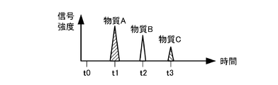
- the separated components are detected by the detector 231.
- the detector 231 detects a signal corresponding to each component corresponding to the holding time of each component in the HPLC column 213. That is, the signal corresponding to each component has time dependence.
- the retention time is the time from flowing into the HPLC column 213 to elution from the HPLC column 213 until it is detected by the detector 231.
- the liquid sample 141a contains substance A, substance B, and substance C
- the retention times of substance A, substance B, and substance C passing through the HPLC column 231 are t1, t2, and t3 (t1 ⁇ t2 ⁇ t3).
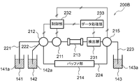
- FIG. 20 is a diagram showing a structural example of an HPLC apparatus 200B adopting a conventional recycling separation method.
- the same components as those of the HPLC apparatus 200A shown in FIG. 18 are designated by the same reference numerals as those in FIG. 18, and the parts having different configurations will be mainly described below.
- the HPLC apparatus 200B shown in FIG. 20 is an HPLC apparatus 200A shown in FIG. 18 to which a recycling separation method is applied, and a second switching valve 215 is added to the downstream side of the detector 231.
- a circulation path closed flow path that circulates through the switching valve 212, the pump 211, the HPLC column 213, the detector 231 and the second switching valve 215 and the buffer portion 214. 224 can be formed.
- the length of the HPLC column can be increased in a pseudo manner to improve the separation resolution. For example, when the circulation for recycling separation is performed three times, the liquid sample 141a and the eluent 142a flow through the HPLC column 213 four times. As a result, a separation resolution equivalent to four times the length of the HPLC column 213 when not circulating can be obtained virtually.
- the same amount of liquid sample 141a and eluent 142a as in the fourth measurement is sent to the HPLC column 213, respectively.
- a total liquid volume four times the total liquid volume of the liquid sample 141a and the eluent 142a required for separation on the HPLC column 213 when not circulating is required.
- the liquid sample 141a and the eluent 142a in the liquid amounts not required for the measurement are sent to the HPLC column 213. It will be liquid. Therefore, unnecessary measurement time is generated.
- the measurement time is four times the required measurement time.
- the HPLC apparatus in this embodiment is an HPLC apparatus adopting a recycling separation method, and when N (N is an integer of 2 or more) times of separation, the liquid to be introduced into the HPLC column from the first to N-1 times.
- the measurement time is shortened by using only the required amount of the total amount of the sample and the eluent.
- FIG. 1 is a diagram showing a configuration example of a liquid analysis system including the liquid analyzer (HPLC device) 100 in the present embodiment.
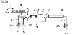
- the HPLC apparatus 100 includes a pump 11, a first buffer unit 12, a first switching valve 13, an HPLC column 14 (corresponding to the column of the present invention), a second switching valve 15, and a second buffer unit 16. , Prepare in this order. Further, the HPLC apparatus 100 includes a liquid sampling flow path 21 (corresponding to the sampling flow path of the present invention), an eluent flow path 22 (corresponding to the mobile phase medium flow path of the present invention), and a main flow path 23. A bypass flow path 24 and a drainage flow path 25 (corresponding to the drainage flow path of the present invention) are provided. Further, the HPLC apparatus 100 includes a detector 31, a control unit 32, and a data processing unit 33.
- the liquid sampling flow path 21 is a flow path for introducing the liquid sample 41a stored in the sample tank 41 into the HPLC column 14, and the eluent flow path 22 is the eluent tank 42 (mobile phase of the present invention). This is a flow path for introducing the eluent 42a (corresponding to the mobile phase medium of the present invention) stored in the medium tank) into the HPLC column 14.
- One end of the liquid sampling flow path 21 and one end of the eluent flow path 22 are connected to the first switching valve 13.
- the main flow path 23 is interposed from one end side to the other end side with a first buffer portion 12, a first switching valve 13, an HPLC column 14, a second switching valve 15, and a second buffer portion 16.
- This is a flow path through which a fluid containing the liquid sample 41a (a mixed solution of the liquid sample 41a and the eluent 42a) flows.
- the first buffer unit 12 and the second buffer unit 16 are composed of, for example, a pipeline (tube) having a predetermined content.
- the pipeline (tube) may be in the shape of a coil, for example.
- the bypass flow path 24 is a flow path connected between the first switching valve 13 and the second switching valve 15.
- the bypass flow path 24 bypasses the HPLC column 14 and is connected to the first switching valve 13 at one end and to the second switching valve 15 at the other end.
- the drainage flow path 25 is a flow path for discharging the fluid in the flow path of the liquid analysis system as the drainage liquid 43a to the drainage tank 43.
- the pump 11 is a liquid feeding section for feeding the liquid sample 41a and / or the eluent 42a to the HPLC column 14, and is connected to the HPLC column 14 via the first switching valve 13 and the first buffer section 12. There is.
- the detector 31 is provided between the HPLC column 14 and the second switching valve 15 in the main flow path 23.
- the liquid sample 41a introduced into the HPLC column 14 is separated for each component by interaction with the stationary phase held inside the HPLC column 14.
- the detector 31 detects the separated components in the HPLC column 14, and sends the detected detection data to the data processing unit 33.
- the data processing unit 33 analyzes the detection data detected by the detection unit 31 to identify and quantify the nutrient solution component.
- the data processing unit 33 sends the analyzed analysis result to the control unit 32.
- the control unit 32 controls the operation of the pump 11, the first switching valve 13, and the second switching valve 15.
- the control unit 32 switches the flow path between the first switching valve 13 and the second switching valve 15 in the main flow path 23 to the bypass flow path 24 by switching the first switching valve 13 and the second switching valve 15. Can be done.
- the control unit 32 can switch the flow direction of the fluid flowing in the flow path of the liquid analysis system by controlling the pump 11.
- the control unit 32 can receive the analysis result analyzed by the data processing unit 33 and transmit it to the outside as necessary, or display the result on a monitor (not shown) or the like.
- each component contained in the liquid sample is separated N times (here, 4 times) using the HPLC column 14, and the separated component is detected each time.
- the control unit 32 shown in FIG. 1 controls the pump 11, the first switching valve 13, and the second switching valve 15, and sends the eluent 42a from the eluent tank 42 to the main flow path 23 and the bypass flow path 24. Fill.
- the control unit 32 switches the first switching valve 13 and controls the pump 11 to suck up the eluate 42a from the eluent tank 42 and supply the sucked eluate 42a to the first buffer unit 12. ..
- the control unit 32 switches between the first switching valve 13 and the second switching valve 15, controls the pump 11, and sends the eluent 42a held by the first buffer unit 12 to the HPLC column 14 side.
- the eluent 42a is filled in a part of the HPLC column 14, the detector 31, and the second buffer section 16.
- the control unit 32 switches between the first switching valve 13 and the second switching valve 15, controls the pump 11, and sends the eluent 42a held by the first buffer unit 12 to the bypass flow path 24 side.
- the eluent 42a is filled in the main flow path 23 including a part of the first buffer part 12, the HPLC column 14, the detector 31, and a part of the second buffer part 16 and the bypass flow path 24.
- the control unit 32 switches the first switching valve 13 and controls the pump 11 to suck up the liquid sample 41a from the sample tank 41 and supply the sucked up liquid sample 41a to the first buffer unit 12.
- the amount of the mixed solution of the eluent 42a and the liquid sample 41a supplied to the first buffer section 12 is such that the mixed solution of the eluent 42a and the liquid sample 41a held by the first buffer section 12 is the HPLC column 14.
- the amount of liquid is adjusted to be equal to or greater than the amount of liquid required for component separation in an HPLC column having a length of N times (here, 4 times) or N times (here, 4 times) of the HPLC column 14.
- FIG. 2A shows a case where the amount of the mixed liquid supplied to the first buffer section 12 is four times the flow rate required for the first component separation in one HPLC column 14.
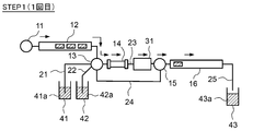
- the control unit 32 controls the first switching valve 13 and the second switching valve 15 to connect the first buffer unit 12 and the HPLC column 14, and also connect the detection unit 31 and the second buffer unit 16. Then, the control unit 32 drives the pump 11 to supply a part of the fluid (mixed liquid of the eluent 42a and the liquid sample 41a) held in the first buffer unit 12 to the HPLC column 14 side. As a result, the fluid held in the first buffer section 12 is introduced into the HPLC column 14. At this time, the liquid amount of the fluid sent out from the first buffer unit 12 and supplied to the HPLC column 14 is the amount of liquid required by one HPLC column 14 for the first component separation.
- each component constituting the liquid sample 41a moves while interacting with the HPLC column 14 which is a stationary phase.
- the time at which each component elutes from the HPLC column 14 is determined by the difference in the strength of interaction between each component and the HPLC column 14. That is, each component contained in the liquid sample 41a is separated by utilizing the difference in the elution time of each component passing through the HPLC column 14. Then, the separated components are detected by the detector 31 arranged after the HPLC column 14. At this time, the detector 31 obtains a signal corresponding to each component corresponding to the elution time of each component eluted from the HPLC column 14.
- the fluid discharged from the detector 31 is supplied to the second buffer unit 16 via the second switching valve 15 and is held by the second buffer unit 16.
- the components 16 having the shortest elution time by the HPLC column 14 are supplied to the second buffer unit 16 in order (in order of elution earlier).
- the second buffer section 16 holds the fluid passing through the HPLC column 14 and the detector 31 until all the first separations and measurements (detection of each component) are completed. That is, as shown in FIG. 2B, one HPLC column 14 sends out a fluid having a liquid amount required for the first component separation from the first buffer unit 12, and this fluid is the HPLC column 14 and the detector. It is held in the second buffer unit 16 via 31.
- the fluid path in the separation step is the first flowing into the second buffer section 16 from the first buffer section 12 via the first switching valve 13, the HPLC column 14, and the second switching valve 15 in this order. It becomes a route.
- a third switching valve may be provided between the flow path 25 and the flow path 25.
- the third switching valve is controlled by the control unit 32 to open and close the flow path connecting the second buffer unit 16 and the drainage flow path 25.
- the control unit 32 controls the first switching valve 13 and the second switching valve 15 to connect the first buffer unit 12 and the second buffer unit 16 via the bypass flow path 24. Then, the control unit 32 drives the pump 11 and returns the fluid held in the second buffer unit 16 to the first buffer unit 12 via the bypass flow path 24, as shown in FIG. 2C. At this time, the amount of the fluid sent from the second buffer unit 16 and supplied to the first buffer unit 12 is the liquid supplied from the first buffer unit 12 to the second buffer unit 16 in STEP 1 (first separation step). The amount (the amount of liquid required for one HPLC column 14 for the first component separation).
- the fluid sent out from the second buffer unit 16 is discharged from the inflow port into which the fluid has flowed in in the above separation step. That is, from the second buffer section 16, the head of the fluid that has flowed into the second buffer section 16 in the separation step is sent out as the tail, and the component that has a long elution time by the HPLC column 14 is sent to the first buffer section 12. It is returned in order from. At this time, the fluid returned to the first buffer unit 12 flows in from the outflow port from which the fluid has flowed out in the separation step. As described above, the fluid path in the recovery step flows from the second buffer section 16 into the first buffer section 12 via the second switching valve 15 and the first switching valve 13 in order, bypassing the HPLC column 14. It becomes the second route to do.
- the control unit 32 controls the pump 11, the first switching valve 13, and the second switching valve 15, and is a mixture of the eluent 42a and the liquid sample 41a held in the first buffer unit 12. Is supplied to the HPLC column 14 side. At this time, the amount of fluid sent out from the first buffer unit 12 and supplied to the HPLC column 14 is twice the amount of liquid required in the first separation step because it is the second separation.
- each component contained in the liquid sample is separated on the HPLC column 14, and the separated component is detected by the detector 31.
- the second measurement in STEP 3 is substantially the case where two HPLC columns 14 used in the first measurement are arranged in series, or HPLC having twice the length of the HPLC column 14 used in the first measurement. The measurement is the same as when using a column. Therefore, the separation resolution of the signal corresponding to each component is higher than that of the first measurement (STEP1).
- the fluid discharged from the detector 31 is supplied to the second buffer unit 16 via the second switching valve 15 and is held by the second buffer unit 16.
- the second buffer section 16 holds the fluid passing through the HPLC column 14 and the detector 31 until the second separation and measurement (detection of each component) are all completed. That is, as shown in FIG. 3A, a fluid having twice the amount of liquid required in the first separation step was sent out from the first buffer unit 12, and this fluid was sent to the HPLC column 14 and detected. It is held in the second buffer unit 16 via the vessel 31.
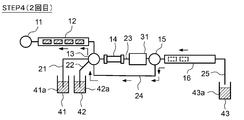
- the control unit 32 controls the pump 11, the first switching valve 13, and the second switching valve 15 to connect the first buffer unit 12 and the second buffer unit 16 via the bypass flow path 24. To connect. Then, the control unit 32 drives the pump 11 and returns the fluid held in the second buffer unit 16 to the first buffer unit 12 via the bypass flow path 24, as shown in FIG. 3B. That is, at this time, the amount of fluid sent from the second buffer unit 16 and supplied to the first buffer unit 12 is supplied from the first buffer unit 12 to the second buffer unit 16 in STEP 3 (second separation step). It is the amount of liquid.
- each component contained in the liquid sample is separated in the HPLC column 14, and the separated component is detected by the detector 31.
- the separation resolution of the signal corresponding to each component at this time is higher than that of the first measurement (STEP1) and the second measurement (STEP3).
- the fluid discharged from the detector 31 is supplied to the second buffer unit 16 via the second switching valve 15 and is held by the second buffer unit 16.
- the second buffer section 16 holds the fluid passing through the HPLC column 14 and the detector 31 until all the third separations and measurements (detection of each component) are completed. That is, as shown in FIG. 4A, a fluid having a liquid volume three times the liquid volume required in the first separation step was sent out from the first buffer unit 12, and this fluid was sent to the HPLC column 14 and detected. It is held in the second buffer unit 16 via the vessel 31.
- the control unit 32 controls the pump 11, the first switching valve 13, and the second switching valve 15 to bypass the first buffer unit 12 and the second buffer unit 16 in the bypass flow path 24. Connect via. Then, the control unit 32 drives the pump 11 and returns the fluid held in the second buffer unit 16 to the first buffer unit 12 via the bypass flow path 24, as shown in FIG. 4B. That is, at this time, the amount of fluid sent from the second buffer unit 16 and supplied to the first buffer unit 12 is supplied from the first buffer unit 12 to the second buffer unit 16 in STEP 5 (third separation step). It is the amount of liquid.
- each component contained in the liquid sample is separated in the HPLC column 14, and the separated component is detected by the detector 31.
- the separation resolution of the signal corresponding to each component at this time is higher than that of the first measurement (STEP1), the second measurement (STEP3), and the third measurement (STEP5).
- the fluid discharged from the detector 31 is supplied to the second buffer unit 16 via the second switching valve 15, and is discharged from the second buffer unit 16 to the drainage tank 43 via the drainage flow path 25. , Retained as drainage 43a. That is, as shown in FIG. 4C, a fluid having a liquid volume four times the liquid volume required in the first separation step is delivered from the first buffer unit 12, and this fluid is obtained by HPLC. It is held in the drainage tank 43 via the column 14, the detector 31, and the second buffer unit 16.
- the fluid flows from the first buffer section 12 to the second buffer section 16 through the main flow path 23 and then is discharged from the drainage flow path 25.
- the residual liquid in the flow path of the liquid analysis system When the residual liquid in the flow path of the liquid analysis system is also discharged, it is discharged to the drainage tank 43 via the drainage flow path 25 via the second buffer unit 16. Further, in the present embodiment, the case where the separation step is performed four times has been described, but the number of separation steps is not limited to the above. The number of separation steps can be appropriately set according to the substance to be detected. This point is the same for the subsequent embodiments.
- the HPLC apparatus 100 in the present embodiment includes a first buffer unit 12, a first switching valve 13, an HPLC column 14, and a second switching valve 15 from one end side to the other end side.
- a detector 31 for detecting the separated components in the HPLC column 14 and a control unit 32 for controlling the pump 11, the first switching valve 13 and the second switching valve 15 are provided.
- the control unit 32 switches the first switching valve 13 and the second switching valve 15 to make the flow path between the first switching valve 13 and the second switching valve 15 in the main flow path 23 into the bypass flow path 24. It can be switched.
- the control unit 32 controls the pump 11, the first switching valve 13, and the second switching valve 15, and at least a part of the fluid (mixture of the liquid sample 41a and the eluent 42a) held by the first buffer unit 12.
- the first path that flows into the second buffer section 16 through the main flow path 23 and the fluid held by the second buffer section 16 are the first switching valve 13 and the second switching valve 15 in the main flow path 23. It is possible to switch between the path and the second path that flows into the first buffer section 12 through the bypass flow path 24.
- the HPLC apparatus 100 elutes into a main flow path 23 including a part of the first buffer part 12, an HPLC column 14, a detector 31, and a part of the second buffer part 16 and a bypass flow path 24.
- a separation step is performed in which the components are supplied to the HPLC column 14 via the valve 13 and the components in the liquid sample are separated by the HPLC column 14.
- a holding step is performed in which the fluid that has passed through the HPLC column 14 is supplied to the second buffer section 16 via the second switching valve 15 in the main flow path 23 and held by the second buffer section 16.
- the first switching valve 13 and the second switching valve 15 are controlled to switch the flow path between the first switching valve 13 and the second switching valve 15 in the main flow path 23 to the bypass flow path 24, and the second switching flow path 24 is used.
- a recovery step is performed in which the fluid held by the buffer unit 16 is returned to the first buffer unit 12 via the second switching valve 15 and the first switching valve 13 in this order, bypassing the HPLC column 14.
- these separation step, holding step, and recovery step are repeated, and after performing the separation step at least N (N is an integer larger than 1) times, detection by the detector 31 is performed (detection step).
- the nth separation step (n is an integer of 1 ⁇ n ⁇ N)
- the first buffer section 12 and the second buffer section 16 are provided in the front and rear stages of the column, and the fluid containing the liquid sample 41a passes from the first buffer section 12 through the HPLC column 14 to the second buffer section. It is possible to switch between the first path that flows into 16 and the second path in which the liquid whose components are separated by the HPLC column 14 bypasses the HPLC column 14 from the second buffer section 16 and flows into the first buffer section 12. Constitute. As a result, the fluid that has once passed through the HPLC column 14 can be returned to the first buffer section 12 and passed through the same HPLC column 14 a plurality of times, and a recycling separation method can be realized. Therefore, it is possible to improve the separation resolution with one short column. Moreover, since the low-pressure pump 11 can be used, the cost can be reduced.
- the fluid flow direction (head and tail) is switched between the first path and the second path to realize recycling separation. do. Specifically, the fluid flowing out from the predetermined outlet of the first buffer section 12 and passing through the HPLC column 14 flows in and is held from the predetermined inlet of the second buffer section 16. Then, the fluid flowing out from the second buffer section 16 flows out from the inflow port of the second buffer section 16, bypasses the HPLC column 14, and flows in from the outflow port of the first buffer section 12.
- the liquid sample whose components are separated in the order of, for example, substances A, B, and C by the HPLC column 14 flows in the order of substances A, B, and C from the inflow port of the second buffer portion 16 and is held once, and then the first. 2
- the substances C, B, and A flow out from the inlet of the buffer unit 16 in this order, and are collected from the outlet of the first buffer unit 12 in this order. Therefore, in the next separation step, the liquid sample can be discharged from the first buffer unit 12 in the order of substances A, B, and C, and can be supplied to the HPLC column 14 again in this order.
- the fluid reciprocates between the first buffer unit 12 and the second buffer unit 16 as described above, and the fluid is passed through the HPLC column 14 N times from the first time to N-1.
- the amount of fluid introduced into the HPLC column 14 can be limited to the amount required for separation. That is, from the first time to the N-1 time, it is possible to prevent the fluid unnecessary for separation from being sent, and the measurement time can be shortened. For example, when four separations are performed on the HPLC column 14, the measurement time can be shortened to 1/4 in the first measurement as compared with the conventional recycling separation method shown in FIG.
- one end of the liquid sampling flow path 21 and one end of the eluent flow path 22 are each connected to the first switching valve 13, and the pump 11 is on the upstream side of the first buffer portion 13 in the first path 23. Is located in. Then, the control unit 32 can control the pump 11 and the first switching valve 13 to switch the injection of the liquid sample 41a and the eluent 42a into the first buffer unit 12. In this way, one pump 11 realizes injection of the liquid sample 41a and the eluent 42a into the first buffer portion 12, and delivery of a mixed solution of the liquid sample 41a and the eluent 42a to the HPLC column 14. can do.
- the pump 11 can be arranged outside the first path and the second path, the fluid can be prevented from passing through the pump 11 during the recycling separation. Therefore, it is possible to prevent the fluid from being dispersed by passing through the pump 11, and it is possible to prevent the separability from being lowered.
- the first buffer section 12 and the second buffer section 16 can be pipelines having a predetermined internal capacity. Therefore, a buffer unit that holds the fluid can be configured with a simple configuration. Further, by forming the buffer portion with a pipeline, it is possible to suppress the diffusion of the fluid in the buffer portion.
- the predetermined content volume can be a volume equal to or larger than the amount of liquid required for separating the components in the HPLC column 14. As a result, the amount of fluid required for component separation can be appropriately supplied from the first buffer unit 12 to the HPLC column 14. Further, in the second buffer section 16, the fluid that has passed through the HPLC column 14 can be appropriately held until all the separations in the HPLC column 14 are completed. Therefore, recycling separation can be appropriately performed.
- the detector 31 is arranged between the HPLC column 14 and the second switching valve 15, the separation component can be detected every time the fluid passes through the HPLC column 14. Further, since the separated component can be detected immediately after passing through the HPLC column 14, the detection by the detector 31 can be performed before the fluid separated from the component is diffused in the HPLC column 14. Therefore, the detection accuracy can be improved.
- the peak shape of the detection signal detected by the detector becomes broader as the number of separations increases. Therefore, for example, when a peak that has been completely separated can be detected at a stage where the number of separations is small, highly accurate analysis can be performed by identifying and quantifying the components based on the peak. For example, when analyzing each component (fertilizer component) in the culture solution using the culture solution used for hydroponic cultivation as a liquid sample, sodium (Na), ammonia (nitrogen: NH 4 ), magnesium (Mg), which are fertilizer components, are used. Of calcium (Ca) and potassium (K), potassium (K) takes longer to elute from the HPLC column 14 as compared with other components. Therefore, depending on the length of the HPLC column 14, a completely separated peak may be obtained even with a single separation. In such a case, potassium (K) may be analyzed in the first detection.
- the detector 31 is not necessarily located on the downstream side of the HPLC column 14 in the first route. It does not have to be placed.
- the detector 31 only needs to be able to detect the fluid that has passed through the HPLC column 14, and may be arranged on the main flow path 23.
- the detector 31 may be located between the first switching valve 13 and the HPLC column 14.
- the HPLC apparatus 100 in the present embodiment is a liquid analyzer using liquid chromatography, and can improve the separation resolution of each component while shortening the measurement time.
- FIG. 5 is a diagram showing a configuration example of a liquid analysis system including the liquid analyzer (HPLC device) 100A in the present embodiment.
- the same components as those of the HPLC apparatus 100 shown in FIG. 1 are designated by the same reference numerals as those in FIG. 1, and the parts having different configurations will be mainly described below.
- the detector 31 is provided between the second buffer portion 16 and the drainage tank 43 in the drainage flow path 25. That is, one end of the HPLC column 14 is directly connected to the first switching valve 13, and the other end of the HPLC column 14 is directly connected to the second switching valve 15.
- each component contained in the liquid sample is separated N times (here, 4 times) using the HPLC column 14, and after the final separation (4th separation), the separated component is detected.
- the control unit 32 shown in FIG. 5 controls the pump 11, the first switching valve 13, and the second switching valve 15 in the same manner as STEP 0 in the first embodiment described above, and controls the main flow path 23 and the bypass flow path. 24 is filled with the eluent 42a from the eluent tank 42.
- the control unit 32 controls the pump 11 and the first switching valve 13 to supply the liquid sample 41a collected from the sample tank 41 to the first buffer unit 12.
- the amount of the mixed solution of the eluent 42a and the liquid sample 41a supplied to the first buffer section 12 is such that the mixed solution of the eluent 42a and the liquid sample 41a held by the first buffer section 12 is the HPLC column 14.
- the amount of liquid is adjusted to be equal to or greater than the amount of liquid required for component separation in an HPLC column having a length of N times (here, 4 times) or N times (here, 4 times) of the HPLC column 14.
- FIG. 6A shows a case where the amount of the mixed liquid supplied to the first buffer section 12 is four times the flow rate required for the first component separation in one HPLC column 14.
- the control unit 32 controls the first switching valve 13 and the second switching valve 15 to connect the first buffer unit 12 and the HPLC column 14, and also connect the HPLC column 14 and the second buffer unit 16. Then, the control unit 32 drives the pump 11 to supply a part of the fluid (mixed liquid of the eluent 42a and the liquid sample 41a) held in the first buffer unit 12 to the HPLC column 14 side. As a result, the fluid held in the first buffer section 12 is introduced into the HPLC column 14. At this time, the amount of fluid sent out from the first buffer unit 12 and supplied to the HPLC column 14 is the flow rate required for one HPLC column 14 in the first component separation.
- the fluid that has passed through the HPLC column 14 is supplied to the second buffer section 16 via the second switching valve 15 and is held by the second buffer section 16.
- the second buffer unit 16 is supplied in order from the component having the shortest elution time by the HPLC column 14 (in the order of earlier elution), as in the separation step in the first embodiment described above.
- the second buffer section 16 holds the fluid passing through the HPLC column 14 until all the first separations are completed. That is, as shown in FIG. 6B, one HPLC column 14 sends out a fluid having a flow rate required for the first component separation from the first buffer unit 12, and this fluid passes through the HPLC column 14 and is second. It is held in the buffer unit 16.
- the fluid path in the separation step is the first flowing into the second buffer section 16 from the first buffer section 12 via the first switching valve 13, the HPLC column 14, and the second switching valve 15 in this order. It becomes a route.
- a third switching valve is provided between the second buffer section 16 and the detector 31. May be provided.
- the third switching valve is controlled by the control unit 32 to open and close the flow path connecting the second buffer unit 16 and the detector 31.
- the control unit 32 controls the first switching valve 13 and the second switching valve 15 to connect the first buffer unit 12 and the second buffer unit 16 via the bypass flow path 24. Then, the control unit 32 drives the pump 11 and returns the fluid held in the second buffer unit 16 to the first buffer unit 12 via the bypass flow path 24, as shown in FIG. 6C. At this time, the amount of the fluid sent from the second buffer unit 16 and supplied to the first buffer unit 12 is the liquid supplied from the first buffer unit 12 to the second buffer unit 16 in STEP 1 (first separation step). Amount (flow rate required for one HPLC column 14 for the first component separation).
- the head of the fluid flowing into the second buffer unit 16 in the separation step is sent out as the tail from the second buffer unit 16, and the first The components that have the longest elution time by the HPLC column 14 are returned to the buffer unit 12 in order.
- the fluid path in the recovery step flows from the second buffer section 16 into the first buffer section 12 via the second switching valve 15 and the first switching valve 13 in order, bypassing the HPLC column 14. It becomes the second route to do.
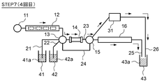
- the fourth separation is the final separation. Therefore, the fluid that has passed through the HPLC column 14 is supplied to the second buffer unit 16 via the second switching valve 15, and is supplied from the second buffer unit 16 to the detector 31. Then, the separated component is detected by the detector 31, the detected data from the detection unit 31 is analyzed by the data processing unit 33 of FIG. 5, and the nutrient solution component is identified and quantified. The analysis result analyzed by the data processing unit 33 is sent to the control unit 32.
- the fluid discharged from the detector 31 is discharged to the drainage tank 43 via the drainage flow path 25 and is held as the drainage 43a. That is, as shown in FIG. 7, a fluid having a liquid volume four times the liquid volume required in the first separation step is delivered from the first buffer unit 12, and this fluid is the HPLC column 14, the first. 2
- the fluid is discharged to the drainage tank 43 via the buffer unit 16 and the detector 31.
- the fluid flows from the first buffer section 12 to the second buffer section 16 through the main flow path 23, then passes through the detector 31 and is discharged from the drainage flow path 25. ..
- the residual liquid in the flow path of the liquid analysis system is also discharged, it is discharged to the drainage tank 43 via the drainage flow path 25 via the second buffer unit 16.
- the detector 31 is arranged outside the main flow path 23 and the bypass flow path 24. Specifically, the detector 31 is arranged on the drainage flow path 25 that discharges the fluid from the downstream side of the second buffer portion 16 in the first path. Therefore, while the fluid is flowing in the first path or the second path, the detector 31 does not detect the separated component, and after the recycling separation is completed, the fluid is sent from the downstream side of the second buffer portion 16. The separated component can be detected at the time of discharge. In this way, the fluid whose components have been separated by the HPLC column 14 can be prevented from being introduced into the detector 31 during the recycling separation.
- the detector 31 has a certain capacity, and fluid diffusion can occur even inside the detector 31. By passing it through the detector 31 at the end after the recycling separation is completed as in the present embodiment, the influence of diffusion inside the detector 31 can be reduced and the detection accuracy can be improved.
- this third embodiment is such that when the separation on the HPLC column 14 is performed a plurality of times, the component finally separated on the HPLC column 14 is detected by the detector 31. Is. For example, when the separation in the HPLC column 14 is performed four times, the detector 31 detects only the components of the liquid sample 41a separated by the HPLC column 14 in the fourth time. That is, the component detection (measurement) by the detector 31 is not performed in the separation steps up to the third time.
- FIG. 8 is a diagram showing a configuration example of a liquid analysis system including the liquid analyzer (HPLC device) 100B in the present embodiment.
- the same components as those of the HPLC apparatus 100A shown in FIG. 5 are designated by the same reference numerals as those in FIG. 5, and the parts having different configurations will be mainly described below.
- the detector 31 is provided between the second switching valve 15 and the drainage tank 43 in the drainage flow path 26. That is, the second buffer unit 16 and the detector 31 are connected to the second switching valve 15, respectively.
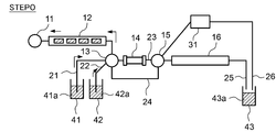
- FIG. 9A shows the operation of the preparation step of [STEP0]
- FIG. 9B shows the operation of the first separation step of [STEP1]
- FIG. 9C shows the operation of the first collection step of [STEP2].
- the operation from the preparation step of [STEP0] to the third recovery step of [STEP6] is the same as the operation of the liquid analysis system of the second embodiment described above. The description is omitted here.
- a third switching valve may be provided between the road and the road 25.
- the third switching valve is controlled by the control unit 32 to open and close the flow path connecting the second buffer unit 16 and the drainage flow path 25.
- the fourth separation is the final separation. Therefore, the control unit 32 controls the second switching valve 15 to supply the fluid that has passed through the HPLC column 14 to the detection unit 31. Then, the separated component is detected by the detector 31, the detected data from the detection unit 31 is analyzed by the data processing unit 33 of FIG. 8, and the nutrient solution component is identified and quantified. The analysis result analyzed by the data processing unit 33 is sent to the control unit 32.
- the fluid discharged from the detector 31 is discharged to the drain tank 43 via the drain flow path 26 and is held as the drain 43a. That is, as shown in FIG. 10, a fluid having a liquid volume four times the liquid volume required in the first separation step is sent out from the first buffer unit 12, and this fluid is sent to the HPLC column 14 and the detection. It is held in the drainage tank 43 via the vessel 31.
- the fluid flows from the first buffer section 12 to the second switching valve 15 through the main flow path 23 and then through the detector 31 without passing through the second buffer section 16. It is discharged from the drainage channel 25.
- the residual liquid in the flow path of the liquid analysis system is discharged, it is discharged to the drainage tank 43 via the drainage flow path 25 via the second buffer unit 16.
- the detector 31 is a fluid via a second switching valve 15 provided between the HPLC column 14 and the second buffer unit 16 in the first path. Is arranged on the drainage flow path 26 for discharging. Therefore, as in the second embodiment described above, it can be passed through the detector 31 at the end after the recycling separation is completed, and the influence of diffusion inside the detector 31 can be reduced.
- the separation component can be detected when the fluid is discharged from the downstream side of the HPLC column 14 and the upstream side of the second buffer portion 16, so that the last It does not pass through the second buffer unit 16 unnecessarily. That is, since the separated component can be detected immediately after the HPLC column 14, the influence of diffusion inside the second buffer portion 16 can be suppressed, and the detection accuracy can be further improved.
- the second buffer section 16 is a pipeline having a predetermined internal volume as described above, and the velocity of the fluid passing through the second buffer section 16 is very slow.
- the detection by the detector 31 can be performed without passing through the second buffer unit 16, so that the detection by the detector 31 is performed after passing through the second buffer unit 16 as described above.
- the measurement time can be significantly shortened as compared with the second embodiment.
- FIG. 11 is a diagram showing a configuration example of a liquid analysis system including the liquid analyzer (HPLC device) 100C in the present embodiment.
- the same components as those of the HPLC apparatus 100A shown in FIG. 5 are designated by the same reference numerals as those in FIG. 5, and the parts having different configurations will be mainly described below.
- the detector 31 is provided in the detection flow path 27.
- the detection flow path 27 is a second bypass flow path provided in parallel with the bypass flow path 24.
- one end (the pipe on the side where the fluid of the detector 31 flows in) is connected to the first switching valve 13, and the other end (the pipe on the side where the fluid of the detector 31 flows out) is the second. It is connected to the switching valve 15.
- each component contained in the liquid sample is separated N times (here, 4 times) using the HPLC column 14.
- the fluid that has passed through the HPLC column 14 is passed through the second switching valve 15 and the second buffer section 16 to the detector. It was sent to 31 to detect the separated component.
- the fluid that has passed through the HPLC column 14 is sent to the detector 31 via the second switching valve 15. , The separated component was detected.
- the fluid that has passed through the HPLC column 14 is once returned to the first buffer section 12, and the fluid returned to the first buffer section 12 is replaced. It is sent to the detector 31 via the first switching valve 13 to detect the separated component. Then, the fluid that has passed through the detector 31 is discharged from the drainage flow path 25 through the second switching valve 15 and the second buffer portion 16.
- FIG. 12A shows the operation of the preparation step of [STEP0]
- FIG. 12B shows the operation of the first separation step of [STEP1]
- FIG. 12C shows the operation of the first collection step of [STEP2].
- the operation from the preparation step of [STEP0] to the third recovery step of [STEP6] is the same as the operation of the liquid analysis system of the second embodiment described above. The description is omitted here.
- a third switching valve may be provided between the road and the road 25.
- the third switching valve is controlled by the control unit 32 to open and close the flow path connecting the second buffer unit 16 and the drainage flow path 25.
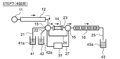
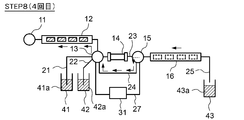
- the control unit 32 controls the pump 11, the first switching valve 13, and the second switching valve 15 to control the mixture of the eluent 42a and the liquid sample 41a held in the first buffer unit 12 on the detector 31 side. It is supplied to (detection flow path 27). As a result, the separated component is detected by the detector 31, the detected data from the detection unit 31 is analyzed by the data processing unit 33 of FIG. 11, and the nutrient solution component is identified and quantified. The analysis result analyzed by the data processing unit 33 is sent to the control unit 32.
- the fluid discharged from the detector 31 passes through the second buffer portion 16 and is discharged to the drainage tank 43 via the drainage flow path 25, and is held as the drainage 43a. That is, as shown in FIG. 13C, a fluid having a liquid amount four times the liquid amount required in the first separation step is sent out from the first buffer unit 12, and this fluid is sent to the detection unit 31 and the first. 2 It is held in the drainage tank 43 via the buffer portion 16. When the residual liquid in the flow path of the liquid analysis system is discharged, it is discharged to the drainage tank 43 via the drainage flow path 25 via the second buffer unit 16.
- the detector 31 bypasses the HPLC column 14 and is connected between the first switching valve 13 and the second switching valve 15. It is arranged on the detection flow path 27, which is a road. Therefore, as in the second embodiment and the third embodiment described above, it can be passed through the detector 31 at the end after the recycling separation is completed, and the influence of diffusion inside the detector 31 can be reduced. can.
- the fluid that has passed through the HPLC column 14 is once returned to the first buffer section 12, and the fluid returned to the first buffer section 12 is detected by the detector.
- the separated component is detected by sending to 31 has been described.
- the separated components of the liquid sample may be detected by the detector 31 before the final separation by the HPLC column 14.
- a second recovery step is performed as shown in FIG. 14A, after the fluid is returned to the first buffer section 12, and before the third separation by the HPLC column 14.
- the separated component may be detected by the detector 31.
- the detection step (STEP-A) shown in FIG. 14B is intervened.
- the control unit 32 controls the pump 11, the first switching valve 13, and the second switching valve 15 to control the mixture of the eluent 42a and the liquid sample 41a held in the first buffer unit 12 on the detector 31 side. Supply to.
- the separated component is detected by the detector 31, the detected data from the detection unit 31 is analyzed by the data processing unit 33 of FIG. 11, and the nutrient solution component is identified and quantified.
- the analysis result analyzed by the data processing unit 33 is sent to the control unit 32.
- the fluid discharged from the detector 31 is held in the second buffer unit 16. At this time, the amount of fluid sent from the first buffer unit 12 and supplied to the detector 31 is 2 of the amount of liquid required in the first separation step because it is after the second separation. It is doubled (Fig. 14B).
- the separated component can be detected by the detector 31 at an arbitrary timing, and then the recycling separation can be restarted. Therefore, for example, it is possible to determine the number of remaining recycling separations or end the recycling separation according to the detection result by the detector 31. That is, when it is determined from the detection result by the detector 31 that the component separation is insufficient, the number of remaining recycling separations is increased, while when it is determined that the component separation is sufficiently performed, the recycling separation is performed. It is possible to change the number of separations while observing the analysis results, such as ending the recycling separation because it is not necessary to restart.
- FIG. 22 is a diagram showing a configuration example of a gas analysis system including the gas analyzer (GC apparatus) 150 according to the embodiment of the present invention.
- the configuration example of the gas analysis system shown in FIG. 1 is a reconstruction of the liquid analysis system shown in FIG. 1 for gas analysis, and those having the same reference numerals as those in FIG. 1 are equivalent components.
- the GC device 150 includes a pump 11, a first buffer unit 12, a first switching valve 13, a GC column 54 (corresponding to the column of the present invention), a second switching valve 15, and a second buffer unit 16. , Prepare in this order. Further, the GC apparatus 150 includes a gas sampling flow path 61 (corresponding to the sampling flow path of the present invention), a carrier gas flow path 62 (corresponding to the mobile phase medium flow path of the present invention), a main flow path 23, and the main flow path 23. A bypass flow path 24 and an exhaust flow path 65 (corresponding to the discharge flow path of the present invention) are provided. Further, the GC device 150 includes a detector 31, a control unit 32, and a data processing unit 33.
- the gas sampling flow path 61 is a flow path for introducing the gas sample 71a stored in the sample tank 41 into the GC column 54
- the carrier gas flow path 62 is the carrier gas tank 72 (the mobile phase of the present invention). This is a flow path for introducing the carrier gas 72a (corresponding to the mobile phase medium of the present invention) stored in the medium tank) into the GC column 54.
- One end of the gas sampling flow path 61 and one end of the carrier gas flow path 62 are connected to the first switching valve 13.
- the main flow path 23 is interposed from one end side to the other end side with a first buffer portion 12, a first switching valve 13, a GC column 54, a second switching valve 15, and a second buffer portion 16.
- This is a flow path through which a fluid containing the gas sample 71a (a mixed gas of the gas sample 71a and the carrier gas 72a) flows.
- the first buffer unit 12 and the second buffer unit 16 are composed of, for example, a pipeline (tube) having a predetermined content.
- the pipeline (tube) may be in the shape of a coil, for example.
- the bypass flow path 24 is a flow path connected between the first switching valve 13 and the second switching valve 15.
- the bypass flow path 24 bypasses the GC column 54 and is connected to the first switching valve 13 at one end and to the second switching valve 15 at the other end.
- the exhaust flow path 65 is a flow path for discharging the abatement substance 73a for abatement of the fluid in the flow path of the gas analysis system to the abatement device 73 mounted inside.
- the fluid (gas) detoxified by the abatement device 73 is discharged to the outside (open to the atmosphere).
- the fluid in the flow path of the gas analysis system does not contain a toxic substance, the fluid is connected to the second switching valve 15 of the second buffer portion 16 without going through the abatement device 73. Is discharged to the outside from the opposite end (open to the atmosphere).
- the pump 11 is a delivery unit for delivering the gas sample 71a and / or the carrier gas 72a to the GC column 54, and is connected to the GC column 54 via the first switching valve 13 and the first buffer unit 12.
- the detector 31 is provided between the GC column 54 and the second switching valve 15 in the main flow path 23.
- the gas sample 71a introduced into the GC column 54 is separated for each component by interaction with the stationary phase held inside the GC column 54.
- the detector 31 detects the components separated in the GC column 54 and sends the detected detection data to the data processing unit 33.
- the data processing unit 33 analyzes the detection data detected by the detection unit 31 to identify and quantify the gas sample component.
- the data processing unit 33 sends the analyzed analysis result to the control unit 32.
- the control unit 32 controls the operation of the pump 11, the first switching valve 13, and the second switching valve 15.
- the control unit 32 switches the flow path between the first switching valve 13 and the second switching valve 15 in the main flow path 23 to the bypass flow path 24 by switching the first switching valve 13 and the second switching valve 15. Can be done.
- the control unit 32 can switch the flow direction of the fluid flowing in the flow path of the gas analysis system by controlling the pump 11.
- the control unit 32 can receive the analysis result analyzed by the data processing unit 33 and transmit it to the outside as necessary, or display the result on a monitor (not shown) or the like.
- the configuration example of the gas analysis system shown in FIG. 22 is a configuration example of the liquid analysis system shown in FIG. 1 except that the analysis target is a gas, and there is no change in the operation example. Therefore, the description of the operation example of the gas analysis system will be omitted. Further, the gas analysis system may adopt the same configuration as the other configuration examples (FIGS. 5, 8, and 11) of the above liquid analysis system. In that case, the operation example is also the same.
Landscapes
- Life Sciences & Earth Sciences (AREA)
- Physics & Mathematics (AREA)
- Health & Medical Sciences (AREA)
- Chemical & Material Sciences (AREA)
- Analytical Chemistry (AREA)
- Biochemistry (AREA)
- General Health & Medical Sciences (AREA)
- General Physics & Mathematics (AREA)
- Immunology (AREA)
- Pathology (AREA)
- Sustainable Development (AREA)
- Treatment Of Liquids With Adsorbents In General (AREA)
Abstract
測定時間を短縮しつつ各成分の分離分解能を向上させることができるクロマトグラフおよび試料分析方法が開示される。 液体分析装置(HPLC装置)は、第1バッファ部(12)、第1切換えバルブ(13)、HPLCカラム(14)、第2切換えバルブ(15)、第2バッファ部(16)が介装された主流路(23)と、HPLCカラム(14)を迂回するバイパス流路(24)と、を備える。制御部(32)は、ポンプ(11)、第1切換えバルブ(13)および第2切換えバルブ(15)を制御して、第1バッファ部(12)が保持する流体の少なくとも一部が、主流路(23)を通って第2バッファ部(16)に流入する第1の経路と、第2バッファ部(16)が保持する流体が、主流路(23)における第1切換えバルブ(13)と第2切換えバルブ(15)との間を、バイパス流路(24)を通って第1バッファ部(12)に流入する第2の経路と、を切換える。
Description
本発明は、クロマトグラフおよび試料分析方法に関する。
従来、試料の成分分析を行う試料分析装置として、クロマトグラフが知られている。クロマトグラフは、移動相媒体をポンプなどによって加圧してカラムを通過させ、分析種を固定相及び移動相との相互作用の差を利用して高性能に分離して検出する分析方法である。気体試料の分析においては、移動相媒体としてキャリアガスと呼ばれる気体を用いるガスクロマトグラフ(Gas Chromatograph)などが使われる。一方、液体試料の分析においては、移動相媒体として溶離液と呼ばれる液体を用いる液体クロマトグラフ(Liquid Chromatograph)などが使われる。
クロマトグラフにおける各成分の分離分解能を向上させるためには、固定相であるカラムの長さを長くして各成分の溶出時間を長くしたり、流路中にカラムを複数本、直列に配置したりすることが考えられる。
しかしながら、カラムの長さを長くしたり、複数本直列に配置したりすると、カラム自体が大型化する。また、カラムの長さを長くした分、当該カラムへ試料および移動相媒体を送出する際の送出圧力も高くする必要があるため、ポンプが大型化する。すなわち、クロマトグラフを採用した試料分析システムが大型化するとともにコストが嵩む。
しかしながら、カラムの長さを長くしたり、複数本直列に配置したりすると、カラム自体が大型化する。また、カラムの長さを長くした分、当該カラムへ試料および移動相媒体を送出する際の送出圧力も高くする必要があるため、ポンプが大型化する。すなわち、クロマトグラフを採用した試料分析システムが大型化するとともにコストが嵩む。
そこで、送出圧力を高くすることなく分離分解能の向上を実現するための技術として、例えば特許文献1(特開2006-201039号公報)には、リサイクル分離方式を採用した高速液体クロマトグラフィー(HPLC:High Performance Liquid Chromatography)が開示されている。この方式は、一度HPLCカラムを通過した液体試料と溶離液とを共に循環させ、同じHPLCカラムに通過させる動作を複数回行うことで、疑似的にHPLCカラムの長さを長くして分離分解能を高める方式である。
このように、同一HPLCカラムに複数回液体試料および溶離液を流すことで、送液圧力はHPLCカラム1本分と同等であって、HPLCカラム複数本分もしくは複数倍の長さのHPLCカラムを用いた場合と同等の分離分解能が得られる。
このように、同一HPLCカラムに複数回液体試料および溶離液を流すことで、送液圧力はHPLCカラム1本分と同等であって、HPLCカラム複数本分もしくは複数倍の長さのHPLCカラムを用いた場合と同等の分離分解能が得られる。
しかしながら、上記のリサイクル分離方式を採用してリサイクル運転を繰返し行っていくと、液体試料中の各成分は互いに分離していくものの、早く溶出する成分が1回前のサイクルで分離している遅く溶出する成分に追いつくことが発生し、折角分離した成分同士が混合する場合がある。
このような不具合を解消するために、例えば特許文献2(特開2010-249588号公報)には、リサイクル運転時の閉流路において、その流路長を長くするための側路を設けた装置構成が開示されている。つまり、カラムから最後に溶出される成分が溶出されるまで、最初に溶出される成分がカラムに流入しないように、閉流路中に、液体試料と溶離液とを保持するためのバッファ部を設ける。これにより、多量の液体試料であっても精度良く分離させることができる。
このような不具合を解消するために、例えば特許文献2(特開2010-249588号公報)には、リサイクル運転時の閉流路において、その流路長を長くするための側路を設けた装置構成が開示されている。つまり、カラムから最後に溶出される成分が溶出されるまで、最初に溶出される成分がカラムに流入しないように、閉流路中に、液体試料と溶離液とを保持するためのバッファ部を設ける。これにより、多量の液体試料であっても精度良く分離させることができる。
上記特許文献2(特開2010-249588号公報)に記載の技術では、例えばリサイクル分離のための循環を3回行い、4回目にカラムによって分離された各成分を検出することで、仮想的には、4倍の長さのカラムと同等の分離分解能が得られる。しかしながら、この場合、カラムには、毎回、カラムでの最後の分離に必要な液体試料および溶離液の総液量が送液される。つまり、1回目、2回目、3回目の測定では、測定に必要な液量に加え、測定に不要な液量の液体試料および溶離液がカラムに送液されることになる。そのため、不要な測定時間が生じる。
そこで、本発明は、クロマトグラフおよび試料分析方法であって、測定時間を短縮しつつ各成分の分離分解能を向上させることができるクロマトグラフおよび試料分析方法を提供することを課題としている。
上記課題を解決するために、本発明に係るクロマトグラフの一態様は、液体もしくは気体である試料を含む流体を送出ポンプと、前記流体が供給され、内部に保持された固定相との相互作用によって前記試料の成分を分離するカラムと、一端側から他端側に向かって、第1バッファ部と、第1切換えバルブと、前記カラムと、第2切換えバルブと、第2バッファ部とが介装された主流路と、前記カラムを迂回して前記第1切換えバルブと前記第2切換えバルブとの間に接続されたバイパス流路と、前記カラムにおいて分離された成分を検出する検出器と、前記ポンプ、前記第1切換えバルブおよび前記第2切換えバルブを制御する制御部と、を備える。前記制御部は、前記第1切換えバルブおよび前記第2切換えバルブを切換えることで、前記主流路における前記第1切換えバルブと前記第2切換えバルブとの間の流路を前記バイパス流路に切換え可能であり、前記ポンプ、前記第1切換えバルブおよび前記第2切換えバルブを制御して、前記第1バッファ部が保持する前記流体の少なくとも一部が、前記主流路を通って前記第2バッファ部に流入する第1の経路と、前記第2バッファ部が保持する前記流体が、前記主流路における前記第1切換えバルブと前記第2切換えバルブとの間を、前記バイパス流路を通って前記第1バッファ部に流入する第2の経路と、を切換える。
このように、カラムの前段と後段とに第1バッファ部と第2バッファ部とを設け、試料を含む流体が第1バッファ部から第1切換えバルブ、カラム、第2切換えバルブを経由して第2バッファ部に流入する第1の経路と、カラムによって成分分離された流体が第2バッファ部からカラムを迂回して第2切換えバルブ、第1切換えバルブを経由して第1バッファ部に流入する第2の経路とを切換え可能に構成する。これにより、一度カラムを通過した流体を再び第1バッファ部に戻し、同じカラムを複数回通過させることが可能となり、リサイクル分離方式を実現することができる。したがって、カラムを大型化することなく、また、ポンプの送出圧力を高くすることなく、分離分解能を向上させることができる。
さらに、従来のリサイクル分離方式のように環状の閉流路を用いた構成とは異なり、第1バッファ部と第2バッファ部との間を流体が往復する構成であるため、流体をN回カラムに通す場合の1回目からN-1回目までにおいては、カラムに導入する流体量を分離に必要な流体量のみとすることができる。つまり、1回目からN-1回目までにおいて、分離には不要な流体を送出しないようにすることができ、測定時間を短縮することができる。
さらに、従来のリサイクル分離方式のように環状の閉流路を用いた構成とは異なり、第1バッファ部と第2バッファ部との間を流体が往復する構成であるため、流体をN回カラムに通す場合の1回目からN-1回目までにおいては、カラムに導入する流体量を分離に必要な流体量のみとすることができる。つまり、1回目からN-1回目までにおいて、分離には不要な流体を送出しないようにすることができ、測定時間を短縮することができる。
また、上記のクロマトグラフにおいて、前記検出器は、前記主流路上に配置されていてもよい。
この場合、流体が第1の経路で流れるたびに、カラムにおいて分離された成分を検出することができる。例えば、検出器が第1の経路におけるカラムの下流側に配置されていれば、流体がカラムを通過するたびに分離成分を検出することができる。また、カラムを通過した流体に対して、都度、分離成分の検出を行うことができるので、例えば分離回数が少ない段階で完全分離したピークを検出できた場合には、そのピークをもとに成分の同定や定量を行うこともできる。
さらに、上記のクロマトグラフにおいて、前記検出器は、前記カラムと前記第2切換えバルブとの間に配置されていてもよい。この場合、カラムを通過した直後で分離成分を検出することができる。そのため、カラムにおいて成分分離した流体が検出器に導入される前に拡散されるのを抑制することができ、検出精度を向上させることができる。
この場合、流体が第1の経路で流れるたびに、カラムにおいて分離された成分を検出することができる。例えば、検出器が第1の経路におけるカラムの下流側に配置されていれば、流体がカラムを通過するたびに分離成分を検出することができる。また、カラムを通過した流体に対して、都度、分離成分の検出を行うことができるので、例えば分離回数が少ない段階で完全分離したピークを検出できた場合には、そのピークをもとに成分の同定や定量を行うこともできる。
さらに、上記のクロマトグラフにおいて、前記検出器は、前記カラムと前記第2切換えバルブとの間に配置されていてもよい。この場合、カラムを通過した直後で分離成分を検出することができる。そのため、カラムにおいて成分分離した流体が検出器に導入される前に拡散されるのを抑制することができ、検出精度を向上させることができる。
また、上記のクロマトグラフにおいて、前記検出器は、前記主流路および前記バイパス流路の外に配置されていてもよい。この場合、流体が第1の経路や第2の経路を流れている間は、検出器による分離成分の検出は行わず、例えばリサイクル分離が終了した後、最後に分離成分の検出を行うことができる。成分分離した流体が不必要に検出器に導入されることがないため、検出精度を向上させることができる。
さらにまた、上記のクロマトグラフにおいて、前記第1の経路における前記第2バッファ部の下流側から前記流体を排出する排出流路をさらに備え、前記検出器は、前記排出流路上に配置されていてもよい。この場合、リサイクル分離が終了した後、第2バッファ部の下流側から流体を排出する際に分離成分の検出を行うことができる。
さらにまた、上記のクロマトグラフにおいて、前記第1の経路における前記第2バッファ部の下流側から前記流体を排出する排出流路をさらに備え、前記検出器は、前記排出流路上に配置されていてもよい。この場合、リサイクル分離が終了した後、第2バッファ部の下流側から流体を排出する際に分離成分の検出を行うことができる。
また、上記のクロマトグラフは、前記第1の経路における前記カラムと前記第2バッファ部との間から前記流体を排出する排出流路をさらに備え、前記検出器は、前記排出流路上に配置されていてもよい。この場合、リサイクル分離が終了した後、カラムと第2バッファ部との間から流体を排出する際に分離成分の検出を行うことができる。最後に不必要に第2バッファ部を通ることがないため、流体の拡散を抑制し、検出精度を向上させることができる。
さらに、上記のクロマトグラフは、前記カラムを迂回して前記第1切換えバルブと前記第2切換えバルブとの間に接続された第2のバイパス流路をさらに備え、前記検出器は、前記第2のバイパス流路上に配置されていてもよい。この場合、任意のタイミングで検出器による分離成分の検出を行い、その後、リサイクル分離を再開させることができる。例えば、検出器による検出結果に応じて残りのリサイクル分離の回数を決定したり、リサイクル分離を終了したりすることも可能である。
さらに、上記のクロマトグラフは、前記カラムを迂回して前記第1切換えバルブと前記第2切換えバルブとの間に接続された第2のバイパス流路をさらに備え、前記検出器は、前記第2のバイパス流路上に配置されていてもよい。この場合、任意のタイミングで検出器による分離成分の検出を行い、その後、リサイクル分離を再開させることができる。例えば、検出器による検出結果に応じて残りのリサイクル分離の回数を決定したり、リサイクル分離を終了したりすることも可能である。
また、上記のクロマトグラフは、試料槽に貯留された前記試料を採取する試料採取流路と、移動相媒体槽に貯留された移動相媒体を採取する移動相媒体流路と、をさらに備え、前記試料採取流路の一端および前記移動相媒体流路の一端は、それぞれ前記第1切換えバルブに接続されており、前記ポンプは、前記第1の経路における前記第1バッファ部の上流側に配置され、前記制御部は、前記ポンプおよび前記第1切換えバルブを制御して、前記第1バッファ部への前記試料と前記移動相媒体との注入を切換え可能であってもよい。
この場合、試料および移動相媒体を第1バッファ部に注入するためのポンプと、試料を含む流体(試料と移動相媒体との混合物)を送出するためのポンプとを、1つのポンプで実現することができる。したがって、ポンプを複数個設ける必要がなく、その分の小型化およびコスト削減を実現することができる。また、ポンプを第1の経路および第2の経路の外に配置することができるので、リサイクル分離中は流体がポンプを通過しないようにすることができる。したがって、ポンプを通過することによる流体の分散を防止することができ、分離能の低下を防止することができる。
この場合、試料および移動相媒体を第1バッファ部に注入するためのポンプと、試料を含む流体(試料と移動相媒体との混合物)を送出するためのポンプとを、1つのポンプで実現することができる。したがって、ポンプを複数個設ける必要がなく、その分の小型化およびコスト削減を実現することができる。また、ポンプを第1の経路および第2の経路の外に配置することができるので、リサイクル分離中は流体がポンプを通過しないようにすることができる。したがって、ポンプを通過することによる流体の分散を防止することができ、分離能の低下を防止することができる。
さらに、上記のクロマトグラフにおいて、前記第1バッファ部および前記第2バッファ部は、所定の内容量を有する管路であってもよい。
この場合、簡易な構成で流体を保持するバッファ部を構成することができる。また、バッファ部を管路により構成することで、バッファ部内における流体の拡散を抑制することができる。なお、拡散を適切に抑制するためには、管路の内径は細い方が好ましい。
この場合、簡易な構成で流体を保持するバッファ部を構成することができる。また、バッファ部を管路により構成することで、バッファ部内における流体の拡散を抑制することができる。なお、拡散を適切に抑制するためには、管路の内径は細い方が好ましい。
また、上記のクロマトグラフにおいて、前記所定の内容量は、前記カラムにおける前記成分の分離に必要な流体量以上の容量とすることができる。
第1バッファ部の内容量をカラムにおける成分の分離に必要な流体量以上の容量とすることで、第1バッファ部からカラムに成分分離に必要な量の流体を適切に供給することができる。また、第2バッファ部の内容量をカラムにおける成分の分離に必要な流体量以上の容量とすることで、カラムにおける分離が全て終了するまで、当該カラムを通過した流体を第2バッファ部において保持することができる。したがって、適切にリサイクル分離を行うことができる。
第1バッファ部の内容量をカラムにおける成分の分離に必要な流体量以上の容量とすることで、第1バッファ部からカラムに成分分離に必要な量の流体を適切に供給することができる。また、第2バッファ部の内容量をカラムにおける成分の分離に必要な流体量以上の容量とすることで、カラムにおける分離が全て終了するまで、当該カラムを通過した流体を第2バッファ部において保持することができる。したがって、適切にリサイクル分離を行うことができる。
さらに、本発明に係る試料分析方法の一態様は、液体もしくは気体である試料を含む流体を送液するポンプと、前記流体が供給され、内部に保持された固定相との相互作用によって前記試料の成分を分離するカラムと、一端側から他端側に向かって、第1バッファ部と、第1切換えバルブと、前記カラムと、第2切換えバルブと、第2バッファ部とが介装された主流路と、前記カラムを迂回して前記第1切換えバルブと前記第2切換えバルブとの間に接続されたバイパス流路と、前記カラムにおいて分離された成分を検出する検出器と、を備えるクロマトグラフにおける試料分析方法であって、前記第1バッファ部が保持する前記流体の少なくとも一部を、前記主流路において前記第1切換えバルブを経由して前記カラムへ供給し、前記カラムによって前記試料中の成分を分離する分離ステップと、前記カラムを通過した前記流体を、前記主流路において前記第2切換えバルブを経由して前記第2バッファ部に供給し、当該第2バッファ部で保持させる保持ステップと、前記第1切換えバルブおよび前記第2切換えバルブを制御して、前記主流路における前記第1切換えバルブと前記第2切換えバルブとの間の流路を前記バイパス流路に切換え、前記第2バッファ部が保持する前記流体を、前記カラムを迂回して前記第2切換えバルブ、前記第1切換えバルブを順に経由して前記第1バッファ部に戻す回収ステップと、前記分離ステップ、前記保持ステップおよび前記回収ステップを繰り返し、少なくとも前記分離ステップをN(Nは、1よりも大きい整数)回行った後、前記検出器による検出を行う検出ステップと、を含む。n(nは、1≦n≦Nの整数)回目の前記分離ステップでは、前記第1バッファ部から前記カラムへ、1回目に当該カラムが前記成分の分離を行うのに必要な流体量のn倍の前記流体を供給する。
このように、分離ステップ、保持ステップ、回収ステップを行うことで、一度カラムを通過した流体を再び第1バッファ部に戻すことができ、これらのステップを繰り返すことでリサイクル分離方式を実現することができる。したがって、分離分解能を向上させることができる。
さらに、n回目の分離ステップでは、第1バッファ部からカラムへ、1回目に当該カラムが成分の分離を行うのに必要な流体量のn倍の流体を供給するので、従来のリサイクル分離方式のように環状の閉流路を用いた場合とは異なり、1回目からN-1回目までにおいて、分離には不要な流体を送出しないようにすることができる。したがって、測定時間を短縮することができる。
さらに、n回目の分離ステップでは、第1バッファ部からカラムへ、1回目に当該カラムが成分の分離を行うのに必要な流体量のn倍の流体を供給するので、従来のリサイクル分離方式のように環状の閉流路を用いた場合とは異なり、1回目からN-1回目までにおいて、分離には不要な流体を送出しないようにすることができる。したがって、測定時間を短縮することができる。
また、上記の試料分析方法の前記検出ステップでは、前記分離ステップを行うたびに、前記検出器による検出を行ってもよい。この場合、例えば、分離回数が少ない段階で完全分離したピークを検出できた場合には、そのピークをもとに成分の同定や定量を行うこともできる。
さらに、上記の試料分析方法の前記検出ステップでは、前記N回目の前記分離ステップの後のみ、前記検出器による検出を行ってもよい。この場合、成分分離した流体が不必要に検出器に導入されることがないため、検出精度を向上させることができる。
また、上記の試料分析方法の前記検出ステップでは、m(mは、1≦m<Nの整数)回目の前記分離ステップの後に、前記検出器による検出を行ってもよい。すなわち、N回の分離が行われるまでの任意のタイミングで検出器による分離成分の検出を行うことができる。この場合、例えば、検出器による検出結果に応じて残りのリサイクル分離の回数を決定したり、リサイクル分離を終了したりすることも可能である。
さらに、上記の試料分析方法の前記検出ステップでは、前記N回目の前記分離ステップの後のみ、前記検出器による検出を行ってもよい。この場合、成分分離した流体が不必要に検出器に導入されることがないため、検出精度を向上させることができる。
また、上記の試料分析方法の前記検出ステップでは、m(mは、1≦m<Nの整数)回目の前記分離ステップの後に、前記検出器による検出を行ってもよい。すなわち、N回の分離が行われるまでの任意のタイミングで検出器による分離成分の検出を行うことができる。この場合、例えば、検出器による検出結果に応じて残りのリサイクル分離の回数を決定したり、リサイクル分離を終了したりすることも可能である。
本発明では、クロマトグラフィーを用いた測定において、測定時間を短縮しつつ各成分の分離分解能を向上させることができる。
上記した本発明の目的、態様及び効果並びに上記されなかった本発明の目的、態様及び効果は、当業者であれば添付図面及び請求の範囲の記載を参照することにより下記の発明を実施するための形態(発明の詳細な説明)から理解できるであろう。
上記した本発明の目的、態様及び効果並びに上記されなかった本発明の目的、態様及び効果は、当業者であれば添付図面及び請求の範囲の記載を参照することにより下記の発明を実施するための形態(発明の詳細な説明)から理解できるであろう。
液体クロマトグラフィーやガスクロマトグラフィーを採用した分析システムは、例えば、テロやパンデミックなどの対策として、毒ガスや爆発物、感染症などの対象物をより早期に発見するための検知システムや、上記対象物の拡大防止を目的として、複数個所での分析情報に基づく状況把握システムとして用いられる。これらのシステムにおける分析装置は、公共施設、交通機関など設置場所を選ばず設置可能で小型のものが望まれる。
毒ガスや爆発物の検査のための分析は、ガスを液体に溶かし込む捕集装置と液体クロマトグラフィーとを組合せることで行うことができる。また、毒ガスや爆発物自体をガスクロマトグラフィーにより直接的に分析することも可能である。
上記の毒ガスとしては、例えばサリン(C4H10FO2)、ソマン(C7H16FO2P)、VXガス(C11H26NO2PS)、マスタードガス(bis(2-chloroethyl) sulfide, C4H8Cl2S)などがあり、爆発物としては、TNT(トリニトロトルエン)、DNT(ジニトロトルエン)などがある。
また、感染症検査においては、対象病原菌やウィルスのRNAもしくはDNAを対象物として、直接的に液体クロマトグラフィーにて分析することも、PCRやLAMP法、ハイブリダイゼーション法、インタカレーター法のなど増感方法を介して液体クロマトグラフィーにて分析することも可能である。
上記の感染症としては、例えば炭疽、鳥インフルエンザ、クリミア・コンゴ出血熱、デング熱、エボラ出血熱、ヘンドラウイルス感染症、肝炎、インフルエンザ、ラッサ熱、マールブルグ熱、髄膜炎症(en:Meningococcal disease)、ニパウイルス感染症、ペスト、リフトバレー熱、重症急性呼吸器症候群(SARS)、天然痘、野兎病、黄熱病などがある。
以下、本発明の実施形態を図面に基づいて説明する。
(第一の実施形態)
本実施形態では、液体試料の成分分析を行うクロマトグラフとして高速液体クロマトグラフィー(HPLC:High Performance Liquid Chromatography )装置を用いた液体分析システムについて説明する。
液体分析システムとしては、上記した例以外に例えば、飲料水等の製造工場において飲料水等の品質をモニタするシステムや、植物工場において植物(野菜等の作物)に必要な養分を水に溶かした養液の成分分析を行うシステム等がある。
(第一の実施形態)
本実施形態では、液体試料の成分分析を行うクロマトグラフとして高速液体クロマトグラフィー(HPLC:High Performance Liquid Chromatography )装置を用いた液体分析システムについて説明する。
液体分析システムとしては、上記した例以外に例えば、飲料水等の製造工場において飲料水等の品質をモニタするシステムや、植物工場において植物(野菜等の作物)に必要な養分を水に溶かした養液の成分分析を行うシステム等がある。
図16は、飲料水等の製造工場における液体分析システムの例を示す図である。
この図16に示すように、飲料水等の製造工場においては、製造する飲料水等の品質をモニタするために、飲料水等を貯蔵する液体タンク81より分析対象の飲料水等の液体82の一部を採取する。そして、採取された液体82は、液体試料採取流路83を介して液体分析装置84に送液され、当該液体分析装置84により成分分析される。
この図16に示すように、飲料水等の製造工場においては、製造する飲料水等の品質をモニタするために、飲料水等を貯蔵する液体タンク81より分析対象の飲料水等の液体82の一部を採取する。そして、採取された液体82は、液体試料採取流路83を介して液体分析装置84に送液され、当該液体分析装置84により成分分析される。
図17は、植物工場における液体分析システムの例を示す図である。
一般に、植物工場においては、植物(野菜等の作物)に必要な養分を水に溶かした養液による養液栽培が行われる。図17では、養液栽培として、養液91を循環させる循環式の水耕栽培の例を示している。
この図17に示すように、作物92が育成される栽培槽93に供給される養液91は、送液ポンプ94により、循環流路95を介して循環する。循環する養液91の一部は、循環流路95の一部から分岐した液体試料採取流路96を介して、例えば自動的に採取され、採取された養液91は液体分析装置97により成分分析される。
一般に、植物工場においては、植物(野菜等の作物)に必要な養分を水に溶かした養液による養液栽培が行われる。図17では、養液栽培として、養液91を循環させる循環式の水耕栽培の例を示している。
この図17に示すように、作物92が育成される栽培槽93に供給される養液91は、送液ポンプ94により、循環流路95を介して循環する。循環する養液91の一部は、循環流路95の一部から分岐した液体試料採取流路96を介して、例えば自動的に採取され、採取された養液91は液体分析装置97により成分分析される。
循環式の水耕栽培の場合、養液が循環するにつれ栽培槽に保持される養液の組成が変化する。植物の生育は養液成分に影響されるので、養液分析の結果に基づき、必要に応じて適宜、養液の調整が行われる。
液体分析装置84、97としては、液体試料に含まれる多項目の成分を簡易に分析することができるHPLC装置を用いることができる。
図18は、従来のHPLC装置200Aの構成例を示す図である。
HPLC装置200Aは、ポンプ211と、切換えバルブ212と、HPLCカラム213と、を備える。制御部232は、ポンプ211および切換えバルブ212の動作を制御して、試料槽141(図16の液体タンク81、図17の栽培槽93に相当)に貯蔵されている液体試料141a、および溶離液槽142に貯蔵されている溶離液142aを、夫々液体試料採取流路221、溶離液流路222を介してHPLCカラム213に導入する。
図18は、従来のHPLC装置200Aの構成例を示す図である。
HPLC装置200Aは、ポンプ211と、切換えバルブ212と、HPLCカラム213と、を備える。制御部232は、ポンプ211および切換えバルブ212の動作を制御して、試料槽141(図16の液体タンク81、図17の栽培槽93に相当)に貯蔵されている液体試料141a、および溶離液槽142に貯蔵されている溶離液142aを、夫々液体試料採取流路221、溶離液流路222を介してHPLCカラム213に導入する。
HPLCカラム213に導入された液体試料141aは、HPLCカラム213により構成成分毎に分離される。そして、検出器231において分離成分が検出され、データ処理部233において検出部231からの検出データが解析され、養液成分の同定や定量が行われる。データ処理部233により分析された分析結果は、例えば、制御部232に送出される。
HPLCカラム213と検出器231とを通過した液体試料141aおよび溶離液142aは、排液流路223を介して排液槽143に排液143aとして保持される。
HPLCカラム213と検出器231とを通過した液体試料141aおよび溶離液142aは、排液流路223を介して排液槽143に排液143aとして保持される。
HPLCカラム213を溶離液142aとともに液体試料141aが流れると、液体試料141aを構成する各成分は、固定相であるHPLCカラム213と相互作用しながら移動する。この各成分とHPLCカラム213との相互作用の強さの相違により、HPLCカラム213から各成分が溶出する時間が決定される。すなわち、HPLCカラム213を通過する各成分の溶出時間の相違を利用して、液体試料141aに含まれる各成分が分離される。
分離された成分は、検出器231により検出される。このとき、検出器231は、各成分のHPLCカラム213での保持時間に対応して、各成分に相当する信号を検出する。つまり、各成分に相当する信号は時間依存性を持つ。ここで、保持時間とは、HPLCカラム213に流入後、HPLCカラム213から溶出して、検出器231により検出されるまでの時間である。
例えば、液体試料141aに物質A、物質B、物質Cが含まれており、HPLCカラム231を通過する物質A、物質B、物質Cの保持時間がt1、t2、t3(t1<t2<t3)であるとき、検出器231からは、図19に示すように各成分(物質A、物質B、物質C)に相当する信号が得られる。
例えば、液体試料141aに物質A、物質B、物質Cが含まれており、HPLCカラム231を通過する物質A、物質B、物質Cの保持時間がt1、t2、t3(t1<t2<t3)であるとき、検出器231からは、図19に示すように各成分(物質A、物質B、物質C)に相当する信号が得られる。
しかしながら、試料によっては、HPLCカラムを1回通過させただけでは十分に各成分を分離ができない場合がある。そこで、各成分の分離分解能を向上させるために、従来、リサイクル分離方式を採用したHPLC装置が提案されている。
図20は、従来のリサイクル分離方式を採用したHPLC装置200Bの構造例を示す図である。なお、図18に示すHPLC装置200Aと同一の構成要素については、図18と同一符号を付し、以下、構成の異なる部分を中心に説明する。
図20は、従来のリサイクル分離方式を採用したHPLC装置200Bの構造例を示す図である。なお、図18に示すHPLC装置200Aと同一の構成要素については、図18と同一符号を付し、以下、構成の異なる部分を中心に説明する。
図20に示すHPLC装置200Bは、図18に示すHPLC装置200Aにリサイクル分離方式を適用したものであり、検出器231の下流側に第2切換えバルブ215が追加されている。切換えバルブ212と第2切換えバルブ215とを制御することで、切換えバルブ212、ポンプ211、HPLCカラム213、検出器231、第2切換えバルブ215およびバッファ部214を循環する循環経路(閉流路)224を形成することができる。
液体試料141aおよび溶離液142aを循環経路224で循環させ、HPLCカラム213を複数回通過させることで、疑似的にHPLCカラムの長さを長くして分離分解能を高めることができる。
例えば、リサイクル分離のための循環を3回行う場合、HPLCカラム213には4回、液体試料141aおよび溶離液142aが流れる。これにより、仮想的には、循環しない場合のHPLCカラム213の4倍の長さと同等の分離分解能が得られる。
この従来のHPLC装置200Bでは、1回目、2回目、3回目の測定において、それぞれ4回目の測定と同量の液量の液体試料141aおよび溶離液142aがHPLCカラム213に送液される。ここで、4回目の測定では、循環しない場合のHPLCカラム213での分離に必要な液体試料141aおよび溶離液142aの総液量の4倍の総液量が必要となる。
例えば、リサイクル分離のための循環を3回行う場合、HPLCカラム213には4回、液体試料141aおよび溶離液142aが流れる。これにより、仮想的には、循環しない場合のHPLCカラム213の4倍の長さと同等の分離分解能が得られる。
この従来のHPLC装置200Bでは、1回目、2回目、3回目の測定において、それぞれ4回目の測定と同量の液量の液体試料141aおよび溶離液142aがHPLCカラム213に送液される。ここで、4回目の測定では、循環しない場合のHPLCカラム213での分離に必要な液体試料141aおよび溶離液142aの総液量の4倍の総液量が必要となる。
つまり、図21に示すように、1回目、2回目、3回目の測定では、測定に必要な液量に加え、測定に不要な液量の液体試料141aおよび溶離液142aをHPLCカラム213に送液することになる。そのため、不要な測定時間が生じる。例えば、1回目の測定の場合、図21に示すとおり、測定に不要な液体試料141aおよび溶離液142aの総液量が、測定に必要な液体試料141aおよび溶離液142aの総液量の3倍となり、測定時間は必要測定時間の4倍となってしまう。
本実施形態におけるHPLC装置は、リサイクル分離方式を採用したHPLC装置であって、N(Nは2以上の整数)回の分離を行う場合、1回目~N-1回目においてHPLCカラムに導入する液体試料および溶離液の総液量を必要量のみとして、測定時間を短縮するものである。
図1は、本実施形態における液体分析装置(HPLC装置)100を備える液体分析システムの構成例を示す図である。
HPLC装置100は、ポンプ11と、第1バッファ部12と、第1切換えバルブ13と、HPLCカラム14(本発明のカラムに相当)と、第2切換えバルブ15と、第2バッファ部16とを、この順番に備える。また、HPLC装置100は、液体試料採取流路21(本発明の試料採取流路に相当)と、溶離液流路22(本発明の移動相媒体流路に相当)と、主流路23と、バイパス流路24と、排液流路25(本発明の排出流路に相当)と、を備える。さらに、HPLC装置100は、検出器31と、制御部32と、データ処理部33と、を備える。
HPLC装置100は、ポンプ11と、第1バッファ部12と、第1切換えバルブ13と、HPLCカラム14(本発明のカラムに相当)と、第2切換えバルブ15と、第2バッファ部16とを、この順番に備える。また、HPLC装置100は、液体試料採取流路21(本発明の試料採取流路に相当)と、溶離液流路22(本発明の移動相媒体流路に相当)と、主流路23と、バイパス流路24と、排液流路25(本発明の排出流路に相当)と、を備える。さらに、HPLC装置100は、検出器31と、制御部32と、データ処理部33と、を備える。
液体試料採取流路21は、試料槽41に貯蔵されている液体試料41aをHPLCカラム14に導入するための流路であり、溶離液流路22は、溶離液槽42(本発明の移動相媒体槽)に貯蔵されている溶離液42a(本発明の移動相媒体に相当)をHPLCカラム14に導入するための流路である。液体試料採取流路21の一端と溶離液流路22の一端とは、第1切換えバルブ13に接続されている。
主流路23は、一端側から他端側に向かって、第1バッファ部12と、第1切換えバルブ13と、HPLCカラム14と、第2切換えバルブ15と、第2バッファ部16とが介装され、液体試料41aを含む流体(液体試料41aと溶離液42aとの混合液)が流れる流路である。ここで、第1バッファ部12および第2バッファ部16は、例えば、所定の内容量を有する管路(チューブ)により構成されている。当該管路(チューブ)は、例えばコイル状であってもよい。
バイパス流路24は、第1切換えバルブ13と第2切換えバルブ15との間に接続された流路である。バイパス流路24は、HPLCカラム14を迂回して、一端が第1切換えバルブ13に、他端が第2切換えバルブ15に接続されている。
排液流路25は、液体分析システムの流路内の流体を、排液43aとして排液槽43に排出するための流路である。
排液流路25は、液体分析システムの流路内の流体を、排液43aとして排液槽43に排出するための流路である。
ポンプ11は、HPLCカラム14に液体試料41aおよび/または溶離液42aを送液するための送液部であり、第1切換えバルブ13および第1バッファ部12を介してHPLCカラム14に接続されている。
検出器31は、主流路23におけるHPLCカラム14と第2切換えバルブ15との間に設けられている。
HPLCカラム14に導入された液体試料41aは、当該HPLCカラム14の内部に保持された固定相との相互作用によって構成成分毎に分離される。検出器31は、HPLCカラム14において分離された成分を検出し、検出された検出データをデータ処理部33に送出する。
検出器31は、主流路23におけるHPLCカラム14と第2切換えバルブ15との間に設けられている。
HPLCカラム14に導入された液体試料41aは、当該HPLCカラム14の内部に保持された固定相との相互作用によって構成成分毎に分離される。検出器31は、HPLCカラム14において分離された成分を検出し、検出された検出データをデータ処理部33に送出する。
データ処理部33は、検出部31によって検出された検出データを分析し、養液成分の同定や定量を行う。データ処理部33は、分析された分析結果を制御部32に送出する。
制御部32は、ポンプ11や第1切換えバルブ13、第2切換えバルブ15の動作を制御する。制御部32は、第1切換えバルブ13および第2切換えバルブ15を切換えることで、主流路23における第1切換えバルブ13と第2切換えバルブ15との間の流路をバイパス流路24に切換えることができる。また、制御部32は、ポンプ11を制御することで、液体分析システムの流路内を流れる流体の流れ方向を切換えることができる。
さらに、制御部32は、データ処理部33により分析された分析結果を受信し、必要に応じて外部に送信したり、不図示のモニタ等に結果を表示したりすることもできる。
制御部32は、ポンプ11や第1切換えバルブ13、第2切換えバルブ15の動作を制御する。制御部32は、第1切換えバルブ13および第2切換えバルブ15を切換えることで、主流路23における第1切換えバルブ13と第2切換えバルブ15との間の流路をバイパス流路24に切換えることができる。また、制御部32は、ポンプ11を制御することで、液体分析システムの流路内を流れる流体の流れ方向を切換えることができる。
さらに、制御部32は、データ処理部33により分析された分析結果を受信し、必要に応じて外部に送信したり、不図示のモニタ等に結果を表示したりすることもできる。
以下、図2A~図4Cを用いて、本実施形態の液体分析システムの動作例について説明する。本動作例では、HPLCカラム14を用いて液体試料に含まれる各成分をN回(ここでは4回)分離し、その度に分離された成分を検出する例を示す。
〔STEP0:事前準備〕
まず、図1に示す制御部32は、ポンプ11、第1切換えバルブ13および第2切換えバルブ15を制御して、主流路23とバイパス流路24とに、溶離液槽42から溶離液42aを充填する。
〔STEP0:事前準備〕
まず、図1に示す制御部32は、ポンプ11、第1切換えバルブ13および第2切換えバルブ15を制御して、主流路23とバイパス流路24とに、溶離液槽42から溶離液42aを充填する。
具体的には、制御部32は、第1切換えバルブ13を切換え、ポンプ11を制御して、溶離液槽42から溶離液42aを吸い上げ、吸い上げた溶離液42aを第1バッファ部12に供給する。次に制御部32は、第1切換えバルブ13および第2切換えバルブ15を切換え、ポンプ11を制御して、第1バッファ部12が保持する溶離液42aをHPLCカラム14側へ送出する。この溶離液42aは、HPLCカラム14、検出器31、第2バッファ部16の一部に充填される。次に制御部32は、第1切換えバルブ13および第2切換えバルブ15を切換え、ポンプ11を制御して、第1バッファ部12が保持する溶離液42aをバイパス流路24側へ送出する。
このようにして、第1バッファ部12の一部、HPLCカラム14、検出器31、第2バッファ部16の一部を含む主流路23と、バイパス流路24とに、溶離液42aが充填される。
その後、制御部32は、第1切換えバルブ13を切換え、ポンプ11を制御して、試料槽41から液体試料41aを吸い上げ、吸い上げた液体試料41aを第1バッファ部12に供給する。
このようにして、第1バッファ部12の一部、HPLCカラム14、検出器31、第2バッファ部16の一部を含む主流路23と、バイパス流路24とに、溶離液42aが充填される。
その後、制御部32は、第1切換えバルブ13を切換え、ポンプ11を制御して、試料槽41から液体試料41aを吸い上げ、吸い上げた液体試料41aを第1バッファ部12に供給する。
ここで、第1バッファ部12への溶離液42aと液体試料41aとの混合液の供給量は、第1バッファ部12が保持する溶離液42aと液体試料41aとの混合液が、HPLCカラム14のN本分(ここでは4本分)、もしくはHPLCカラム14のN倍(ここでは4倍)の長さのHPLCカラムにおいて成分の分離に必要な液量以上となるように、調整される。
なお、図2Aでは、第1バッファ部12への混合液の供給量が、1本のHPLCカラム14が1回目の成分分離で必要な流量の4倍である場合を示している。
なお、図2Aでは、第1バッファ部12への混合液の供給量が、1本のHPLCカラム14が1回目の成分分離で必要な流量の4倍である場合を示している。
〔STEP1:1回目の分離〕
制御部32は、第1切換えバルブ13および第2切換えバルブ15を制御して、第1バッファ部12とHPLCカラム14とを接続するとともに、検出部31と第2バッファ部16とを接続する。そして、制御部32は、ポンプ11を駆動し、第1バッファ部12に保持されている流体(溶離液42aと液体試料41aとの混合液)の一部を、HPLCカラム14側へ供給する。これにより、第1バッファ部12に保持されている流体がHPLCカラム14に導入される。
このとき第1バッファ部12から送出され、HPLCカラム14に供給される流体の液量は、1本のHPLCカラム14が1回目の成分分離で必要な液量である。
制御部32は、第1切換えバルブ13および第2切換えバルブ15を制御して、第1バッファ部12とHPLCカラム14とを接続するとともに、検出部31と第2バッファ部16とを接続する。そして、制御部32は、ポンプ11を駆動し、第1バッファ部12に保持されている流体(溶離液42aと液体試料41aとの混合液)の一部を、HPLCカラム14側へ供給する。これにより、第1バッファ部12に保持されている流体がHPLCカラム14に導入される。
このとき第1バッファ部12から送出され、HPLCカラム14に供給される流体の液量は、1本のHPLCカラム14が1回目の成分分離で必要な液量である。
HPLCカラム14を、溶離液42aとともに液体試料41aが流れると、液体試料41aを構成する各成分は、固定相であるHPLCカラム14と相互作用しながら移動する。この各成分とHPLCカラム14との相互作用の強さの相違により、HPLCカラム14から各成分が溶出する時間が決定される。すなわち、HPLCカラム14を通過する各成分の溶出時間の相違を利用して、液体試料41aに含まれる各成分が分離される。
そして、分離された成分は、HPLCカラム14の後段に配置された検出器31によって検出される。このとき、検出器31は、HPLCカラム14から溶出する各成分の溶出時間に対応して、各成分に相当する信号を得る。
そして、分離された成分は、HPLCカラム14の後段に配置された検出器31によって検出される。このとき、検出器31は、HPLCカラム14から溶出する各成分の溶出時間に対応して、各成分に相当する信号を得る。
検出器31から排出される流体は、第2切換えバルブ15を介して第2バッファ部16に供給され、当該第2バッファ部16で保持される。このとき第2バッファ部16には、HPLCカラム14による溶出時間が短い成分から順に(早く溶出された順に)供給される。
第2バッファ部16は、1回目の分離および測定(各成分の検出)が全て終了するまで、HPLCカラム14および検出器31を通過する流体を保持する。つまり、図2Bに示すように、第1バッファ部12からは、1本のHPLCカラム14が1回目の成分分離で必要な液量の流体が送出され、この流体が、HPLCカラム14および検出器31を経て第2バッファ部16に保持される。
このように、分離ステップにおける流体の経路は、第1バッファ部12から第1切換えバルブ13、HPLCカラム14、第2切換えバルブ15を順に経由して、第2バッファ部16に流入する第1の経路となる。
第2バッファ部16は、1回目の分離および測定(各成分の検出)が全て終了するまで、HPLCカラム14および検出器31を通過する流体を保持する。つまり、図2Bに示すように、第1バッファ部12からは、1本のHPLCカラム14が1回目の成分分離で必要な液量の流体が送出され、この流体が、HPLCカラム14および検出器31を経て第2バッファ部16に保持される。
このように、分離ステップにおける流体の経路は、第1バッファ部12から第1切換えバルブ13、HPLCカラム14、第2切換えバルブ15を順に経由して、第2バッファ部16に流入する第1の経路となる。
なお、この分離ステップにおいて第2バッファ部16に流入した流体の少なくとも一部が排液流路25を介して排液槽43に流入することを防止するために、第2バッファ部16と排液流路25との間に第3切換えバルブを設けてもよい。この場合、第3切換えバルブは、制御部32によって、第2バッファ部16と排液流路25とを接続する流路を開閉するように制御される。
〔STEP2:1回目の回収〕
制御部32は、第1切換えバルブ13および第2切換えバルブ15を制御して、第1バッファ部12と第2バッファ部16とを、バイパス流路24を介して接続する。そして、制御部32は、ポンプ11を駆動し、図2Cに示すように、第2バッファ部16に保持されている流体を、バイパス流路24を介して第1バッファ部12へ戻す。
このとき第2バッファ部16から送出され、第1バッファ部12に供給される流体の液量は、STEP1(1回目の分離ステップ)で第1バッファ部12から第2バッファ部16に供給した液量(1本のHPLCカラム14が1回目の成分分離で必要な液量)である。
制御部32は、第1切換えバルブ13および第2切換えバルブ15を制御して、第1バッファ部12と第2バッファ部16とを、バイパス流路24を介して接続する。そして、制御部32は、ポンプ11を駆動し、図2Cに示すように、第2バッファ部16に保持されている流体を、バイパス流路24を介して第1バッファ部12へ戻す。
このとき第2バッファ部16から送出され、第1バッファ部12に供給される流体の液量は、STEP1(1回目の分離ステップ)で第1バッファ部12から第2バッファ部16に供給した液量(1本のHPLCカラム14が1回目の成分分離で必要な液量)である。
また、第2バッファ部16から送出される流体は、上記の分離ステップにおいて流体が流入された流入口から流出される。つまり、第2バッファ部16からは、分離ステップにおいて第2バッファ部16に流入された流体の先頭が後尾となって送出され、第1バッファ部12には、HPLCカラム14による溶出時間が長い成分から順に戻される。このとき第1バッファ部12に戻される流体は、分離ステップにおいて流体が流出された流出口から流入される。
このように、回収ステップにおける流体の経路は、第2バッファ部16から、HPLCカラム14を迂回して第2切換えバルブ15、第1切換えバルブ13を順に経由して、第1バッファ部12に流入する第2の経路となる。
このように、回収ステップにおける流体の経路は、第2バッファ部16から、HPLCカラム14を迂回して第2切換えバルブ15、第1切換えバルブ13を順に経由して、第1バッファ部12に流入する第2の経路となる。
〔STEP3:2回目の分離〕
上述したSTEP1と同様、制御部32は、ポンプ11、第1切換えバルブ13および第2切換えバルブ15を制御して、第1バッファ部12に保持されている溶離液42aおよび液体試料41aの混合液を、HPLCカラム14側へ供給する。
このとき第1バッファ部12から送出され、HPLCカラム14に供給される流体の液量は、2回目の分離であるので、1回目の分離ステップで必要であった液量の2倍となる。
上述したSTEP1と同様、制御部32は、ポンプ11、第1切換えバルブ13および第2切換えバルブ15を制御して、第1バッファ部12に保持されている溶離液42aおよび液体試料41aの混合液を、HPLCカラム14側へ供給する。
このとき第1バッファ部12から送出され、HPLCカラム14に供給される流体の液量は、2回目の分離であるので、1回目の分離ステップで必要であった液量の2倍となる。
そして、STEP1における1回目の測定と同様、HPLCカラム14において液体試料に含まれる各成分が分離され、分離された成分が検出器31で検出される。
このSTEP3における2回目の測定は、実質的に1回目の測定で用いたHPLCカラム14を2本直列に配置した場合、あるいは1回目の測定で用いたHPLCカラム14の2倍の長さのHPLCカラムを用いた場合と同等の測定となる。よって、各成分に相当する信号の分離分解能は、1回目の測定(STEP1)と比較すると高くなる。
このSTEP3における2回目の測定は、実質的に1回目の測定で用いたHPLCカラム14を2本直列に配置した場合、あるいは1回目の測定で用いたHPLCカラム14の2倍の長さのHPLCカラムを用いた場合と同等の測定となる。よって、各成分に相当する信号の分離分解能は、1回目の測定(STEP1)と比較すると高くなる。
検出器31から排出される流体は、第2切換えバルブ15を介して第2バッファ部16に供給され、当該第2バッファ部16で保持される。
第2バッファ部16は、2回目の分離および測定(各成分の検出)が全て終了するまで、HPLCカラム14および検出器31を通過する流体を保持する。つまり、図3Aに示すように、第1バッファ部12からは、1回目の分離ステップで必要であった液量の2倍の液量の流体が送出され、この流体が、HPLCカラム14および検出器31を経て第2バッファ部16に保持される。
第2バッファ部16は、2回目の分離および測定(各成分の検出)が全て終了するまで、HPLCカラム14および検出器31を通過する流体を保持する。つまり、図3Aに示すように、第1バッファ部12からは、1回目の分離ステップで必要であった液量の2倍の液量の流体が送出され、この流体が、HPLCカラム14および検出器31を経て第2バッファ部16に保持される。
〔STEP4:2回目の回収〕
上述したSTEP2と同様、制御部32は、ポンプ11、第1切換えバルブ13および第2切換えバルブ15を制御して、第1バッファ部12と第2バッファ部16とを、バイパス流路24を介して接続する。そして、制御部32は、ポンプ11を駆動し、図3Bに示すように、第2バッファ部16に保持されている流体を、バイパス流路24を介して第1バッファ部12へ戻す。
つまり、このとき第2バッファ部16から送出され、第1バッファ部12に供給される流体の液量は、STEP3(2回目の分離ステップ)で第1バッファ部12から第2バッファ部16に供給した液量である。
上述したSTEP2と同様、制御部32は、ポンプ11、第1切換えバルブ13および第2切換えバルブ15を制御して、第1バッファ部12と第2バッファ部16とを、バイパス流路24を介して接続する。そして、制御部32は、ポンプ11を駆動し、図3Bに示すように、第2バッファ部16に保持されている流体を、バイパス流路24を介して第1バッファ部12へ戻す。
つまり、このとき第2バッファ部16から送出され、第1バッファ部12に供給される流体の液量は、STEP3(2回目の分離ステップ)で第1バッファ部12から第2バッファ部16に供給した液量である。
〔STEP5:3回目の分離〕
上述したSTEP1、STEP3と同様の手順で、第1バッファ部12に保持されている溶離液42aおよび液体試料41aの混合液を、HPLCカラム14側へ供給する。
このとき第1バッファ部12から送出され、HPLCカラム14に供給される流体の液量は、3回目の分離であるので、1回目の分離ステップで必要であった液量の3倍となる。
上述したSTEP1、STEP3と同様の手順で、第1バッファ部12に保持されている溶離液42aおよび液体試料41aの混合液を、HPLCカラム14側へ供給する。
このとき第1バッファ部12から送出され、HPLCカラム14に供給される流体の液量は、3回目の分離であるので、1回目の分離ステップで必要であった液量の3倍となる。
HPLCカラム14に混合液が供給されると、当該HPLCカラム14において液体試料に含まれる各成分が分離され、分離された成分が検出器31で検出される。このときの各成分に相当する信号の分離分解能は、1回目の測定(STEP1)および2回目の測定(STEP3)と比較すると高くなる。
そして、検出器31から排出される流体は、第2切換えバルブ15を介して第2バッファ部16に供給され、当該第2バッファ部16で保持される。第2バッファ部16は、3回目の分離および測定(各成分の検出)が全て終了するまで、HPLCカラム14および検出器31を通過する流体を保持する。つまり、図4Aに示すように、第1バッファ部12からは、1回目の分離ステップで必要であった液量の3倍の液量の流体が送出され、この流体が、HPLCカラム14および検出器31を経て第2バッファ部16に保持される。
そして、検出器31から排出される流体は、第2切換えバルブ15を介して第2バッファ部16に供給され、当該第2バッファ部16で保持される。第2バッファ部16は、3回目の分離および測定(各成分の検出)が全て終了するまで、HPLCカラム14および検出器31を通過する流体を保持する。つまり、図4Aに示すように、第1バッファ部12からは、1回目の分離ステップで必要であった液量の3倍の液量の流体が送出され、この流体が、HPLCカラム14および検出器31を経て第2バッファ部16に保持される。
〔STEP6:3回目の回収〕
上述したSTEP2、STEP4と同様、制御部32は、ポンプ11、第1切換えバルブ13および第2切換えバルブ15を制御して、第1バッファ部12と第2バッファ部16とを、バイパス流路24を介して接続する。そして、制御部32は、ポンプ11を駆動し、図4Bに示すように、第2バッファ部16に保持されている流体を、バイパス流路24を介して第1バッファ部12へ戻す。
つまり、このとき第2バッファ部16から送出され、第1バッファ部12に供給される流体の液量は、STEP5(3回目の分離ステップ)で第1バッファ部12から第2バッファ部16に供給した液量である。
上述したSTEP2、STEP4と同様、制御部32は、ポンプ11、第1切換えバルブ13および第2切換えバルブ15を制御して、第1バッファ部12と第2バッファ部16とを、バイパス流路24を介して接続する。そして、制御部32は、ポンプ11を駆動し、図4Bに示すように、第2バッファ部16に保持されている流体を、バイパス流路24を介して第1バッファ部12へ戻す。
つまり、このとき第2バッファ部16から送出され、第1バッファ部12に供給される流体の液量は、STEP5(3回目の分離ステップ)で第1バッファ部12から第2バッファ部16に供給した液量である。
〔STEP7:4回目の分離〕
上述したSTEP1、STEP3、STEP5と同様の手順で、第1バッファ部12に保持されている溶離液42aおよび液体試料41aの混合液を、HPLCカラム14側へ供給する。
このとき第1バッファ部12から送出され、HPLCカラム14に供給される流体の液量は、4回目の分離であるので、1回目の分離ステップで必要であった液量の4倍となる。
上述したSTEP1、STEP3、STEP5と同様の手順で、第1バッファ部12に保持されている溶離液42aおよび液体試料41aの混合液を、HPLCカラム14側へ供給する。
このとき第1バッファ部12から送出され、HPLCカラム14に供給される流体の液量は、4回目の分離であるので、1回目の分離ステップで必要であった液量の4倍となる。
HPLCカラム14に混合液が供給されると、当該HPLCカラム14において液体試料に含まれる各成分が分離され、分離された成分が検出器31で検出される。このときの各成分に相当する信号の分離分解能は、1回目の測定(STEP1)、2回目の測定(STEP3)および3回目の測定(STEP5)と比較すると高くなる。
そして、検出器31から排出される流体は、第2切換えバルブ15を介して第2バッファ部16に供給され、第2バッファ部16から排液流路25を介して排液槽43に排出され、排液43aとして保持される。つまり、図4Cに示すように、第1バッファ部12からは、1回目の分離ステップで必要であった液量の4倍の液量の流体が送出され、この流体が、この流体が、HPLCカラム14、検出器31および第2バッファ部16を経て排液槽43に保持される。
このように、最後の分離ステップでは、流体は、第1バッファ部12から第2バッファ部16へ主流路23を通って流れた後、排液流路25から排出される。
そして、検出器31から排出される流体は、第2切換えバルブ15を介して第2バッファ部16に供給され、第2バッファ部16から排液流路25を介して排液槽43に排出され、排液43aとして保持される。つまり、図4Cに示すように、第1バッファ部12からは、1回目の分離ステップで必要であった液量の4倍の液量の流体が送出され、この流体が、この流体が、HPLCカラム14、検出器31および第2バッファ部16を経て排液槽43に保持される。
このように、最後の分離ステップでは、流体は、第1バッファ部12から第2バッファ部16へ主流路23を通って流れた後、排液流路25から排出される。
なお、液体分析システムの流路における残液を排出する場合も、第2バッファ部16を経由して排液流路25を介して排液槽43に排出される。
また、本実施形態では、分離ステップを4回行う場合について説明したが、分離ステップの回数は上記に限定されない。分離ステップの回数は、検出対象の物質に応じて適宜設定することが可能である。この点は、以降の実施形態についても同様である。
また、本実施形態では、分離ステップを4回行う場合について説明したが、分離ステップの回数は上記に限定されない。分離ステップの回数は、検出対象の物質に応じて適宜設定することが可能である。この点は、以降の実施形態についても同様である。
以上説明したように、本実施形態におけるHPLC装置100は、一端側から他端側に向かって、第1バッファ部12と、第1切換えバルブ13と、HPLCカラム14と、第2切換えバルブ15と、第2バッファ部16とが介装された主流路23と、HPLCカラム14を迂回して第1切換えバルブ12と第2切換えバルブ15との間に接続されたバイパス流路24と、を備える。また、HPLCカラム14において分離された成分を検出する検出器31と、ポンプ11、第1切換えバルブ13および第2切換えバルブ15を制御する制御部32と、を備える。
そして、制御部32は、第1切換えバルブ13および第2切換えバルブ15を切換えることで、主流路23における第1切換えバルブ13と第2切換えバルブ15との間の流路をバイパス流路24に切換えることができる。制御部32は、ポンプ11、第1切換えバルブ13および第2切換えバルブ15を制御して、第1バッファ部12が保持する流体(液体試料41aと溶離液42aとの混合液)の少なくとも一部が、主流路23を通って第2バッファ部16に流入する第1の経路と、第2バッファ部16が保持する流体が、主流路23における第1切換えバルブ13と第2切換えバルブ15との間を、バイパス流路24を通って第1バッファ部12に流入する第2の経路と、を切換えることができる。
より具体的には、HPLC装置100は、第1バッファ部12の一部、HPLCカラム14、検出器31、第2バッファ部16の一部を含む主流路23と、バイパス流路24とに溶離液42aが充填された状態で、液体試料41aを第1バッファ部12に供給する事前準備を行った後、第1バッファ部12が保持する流体の少なくとも一部を、主流路23において第1切換えバルブ13を経由してHPLCカラム14へ供給し、HPLCカラム14によって液体試料中の成分を分離する分離ステップを行う。
次に、HPLCカラム14を通過した流体を、主流路23において第2切換えバルブ15を経由して第2バッファ部16に供給し、当該第2バッファ部16で保持させる保持ステップを行う。
次に、HPLCカラム14を通過した流体を、主流路23において第2切換えバルブ15を経由して第2バッファ部16に供給し、当該第2バッファ部16で保持させる保持ステップを行う。
次に、第1切換えバルブ13および第2切換えバルブ15を制御して、主流路23における第1切換えバルブ13と第2切換えバルブ15との間の流路をバイパス流路24に切換え、第2バッファ部16が保持する流体を、HPLCカラム14を迂回して第2切換えバルブ15、第1切換えバルブ13を順に経由して第1バッファ部12に戻す回収ステップを行う。
そして、これら分離ステップ、保持ステップおよび回収ステップを繰り返し、少なくとも分離ステップをN(Nは、1よりも大きい整数)回行った後、検出器31による検出を行う(検出ステップ)。
ここで、n(nは、1≦n≦Nの整数)回目の分離ステップでは、第1バッファ部12からHPLCカラム14へ、1回目に当該カラムが成分の分離を行うのに必要な液量のn倍の流体を供給する。
そして、これら分離ステップ、保持ステップおよび回収ステップを繰り返し、少なくとも分離ステップをN(Nは、1よりも大きい整数)回行った後、検出器31による検出を行う(検出ステップ)。
ここで、n(nは、1≦n≦Nの整数)回目の分離ステップでは、第1バッファ部12からHPLCカラム14へ、1回目に当該カラムが成分の分離を行うのに必要な液量のn倍の流体を供給する。
このように、カラムの前段と後段とに第1バッファ部12と第2バッファ部16とを設け、液体試料41aを含む流体が第1バッファ部12からHPLCカラム14を通過して第2バッファ部16に流入する第1の経路と、HPLCカラム14によって成分分離された流体が第2バッファ部16からHPLCカラム14を迂回して第1バッファ部12に流入する第2の経路とを切換え可能に構成する。これにより、一度HPLCカラム14を通過した流体を再び第1バッファ部12に戻し、同じHPLCカラム14を複数回通過させることが可能となり、リサイクル分離方式を実現することができる。したがって、短いカラム1本で分離分解能の向上を実現することができる。また、低圧のポンプ11を使用可能となるため、コストを削減することができる。
さらに、従来のリサイクル分離方式のように環状の閉流路を用いた構成とは異なり、第1の経路と第2の経路とで流体の流れ方向(先頭と後尾)を切換えてリサイクル分離を実現する。
具体的には、第1バッファ部12の所定の流出口から流出しHPLCカラム14を通過した流体は、第2バッファ部16の所定の流入口から流入し保持される。そして、第2バッファ部16から流出される流体は、第2バッファ部16の上記流入口から流出し、HPLCカラム14を迂回して第1バッファ部12の上記流出口から流入される。つまり、HPLCカラム14によって例えば物質A、B、Cの順に成分分離された液体試料は、第2バッファ部16の流入口から物質A、B、Cの順に流入して一旦保持された後、第2バッファ部16の流入口から物質C、B、Aの順に流出して第1バッファ部12の上記流出口からこの順番で回収される。そのため、次の分離ステップでは、第1バッファ部12から物質A、B、Cの順に液体試料を流出することができ、この順番で再びHPLCカラム14に供給することができる。
具体的には、第1バッファ部12の所定の流出口から流出しHPLCカラム14を通過した流体は、第2バッファ部16の所定の流入口から流入し保持される。そして、第2バッファ部16から流出される流体は、第2バッファ部16の上記流入口から流出し、HPLCカラム14を迂回して第1バッファ部12の上記流出口から流入される。つまり、HPLCカラム14によって例えば物質A、B、Cの順に成分分離された液体試料は、第2バッファ部16の流入口から物質A、B、Cの順に流入して一旦保持された後、第2バッファ部16の流入口から物質C、B、Aの順に流出して第1バッファ部12の上記流出口からこの順番で回収される。そのため、次の分離ステップでは、第1バッファ部12から物質A、B、Cの順に液体試料を流出することができ、この順番で再びHPLCカラム14に供給することができる。
そして、本実施形態では、上記のような第1バッファ部12と第2バッファ部16との間を流体が往復する構成により、流体をN回HPLCカラム14に通す場合の1回目からN-1回目までにおいては、HPLCカラム14に導入する流体の液量を分離に必要な液量のみとすることができる。つまり、1回目からN-1回目までにおいて、分離には不要な流体を送液しないようにすることができ、測定時間を短縮することができる。
例えば、HPLCカラム14において4回の分離を行う場合、1回目の測定では、図21に示す従来のリサイクル分離方式と比較して、測定時間を1/4に短縮することができる。
例えば、HPLCカラム14において4回の分離を行う場合、1回目の測定では、図21に示す従来のリサイクル分離方式と比較して、測定時間を1/4に短縮することができる。
また、液体試料採取流路21の一端および溶離液流路22の一端は、それぞれ第1切換えバルブ13に接続されており、ポンプ11は、第1の経路23における第1バッファ部13の上流側に配置されている。そして、制御部32は、ポンプ11および第1切換えバルブ13を制御して、第1バッファ部12への液体試料41aと溶離液42aとの注入を切換えることができる。
このように、1つのポンプ11によって、液体試料41aや溶離液42aの第1バッファ部12への注入と、液体試料41aと溶離液42aとの混合液のHPLCカラム14への送液とを実現することができる。したがって、ポンプを複数個設ける必要がなく、その分の小型化およびコスト削減を実現することができる。また、ポンプ11を第1の経路および第2の経路の外に配置することができるので、リサイクル分離中は流体がポンプ11を通過しないようにすることができる。したがって、ポンプ11を通過することによる流体の分散を防止することができ、分離能の低下を防止することができる。
このように、1つのポンプ11によって、液体試料41aや溶離液42aの第1バッファ部12への注入と、液体試料41aと溶離液42aとの混合液のHPLCカラム14への送液とを実現することができる。したがって、ポンプを複数個設ける必要がなく、その分の小型化およびコスト削減を実現することができる。また、ポンプ11を第1の経路および第2の経路の外に配置することができるので、リサイクル分離中は流体がポンプ11を通過しないようにすることができる。したがって、ポンプ11を通過することによる流体の分散を防止することができ、分離能の低下を防止することができる。
また、第1バッファ部12および第2バッファ部16は、所定の内容量を有する管路とすることができる。したがって、簡易な構成で流体を保持するバッファ部を構成することができる。また、バッファ部を管路により構成することで、バッファ部内における流体の拡散を抑制することができる。
ここで、上記所定の内容量は、HPLCカラム14における成分の分離に必要な液量以上の容量とすることができる。これにより、第1バッファ部12からHPLCカラム14には、成分分離に必要な液量の流体を適切に供給することができる。また、第2バッファ部16においては、HPLCカラム14における分離が全て終了するまで、当該HPLCカラム14を通過した流体を適切に保持することができる。したがって、適切にリサイクル分離を行うことができる。
ここで、上記所定の内容量は、HPLCカラム14における成分の分離に必要な液量以上の容量とすることができる。これにより、第1バッファ部12からHPLCカラム14には、成分分離に必要な液量の流体を適切に供給することができる。また、第2バッファ部16においては、HPLCカラム14における分離が全て終了するまで、当該HPLCカラム14を通過した流体を適切に保持することができる。したがって、適切にリサイクル分離を行うことができる。
さらに、検出器31をHPLCカラム14と第2切換えバルブ15との間に配置するので、流体がHPLCカラム14を通過するたびに分離成分を検出することができる。また、HPLCカラム14を通過した直後で分離成分を検出することができので、HPLCカラム14において成分分離した流体が拡散される前に検出器31での検出を行うことができる。したがって、検出精度を向上させることができる。
また、検出器において検出される検出信号のピーク形状は、分離回数が増えるほどブロード化してくる。そのため、例えば、分離回数が少ない段階で完全分離したピークを検出できる場合には、そのピークをもとに成分の同定や定量を行えば、高精度な分析が可能となる。
例えば、水耕栽培に用いる培養液を液体試料として培養液中の各成分(肥料成分)の分析を行う場合、肥料成分であるナトリウム(Na)、アンモニア(窒素:NH4)、マグネシウム(Mg)、カルシウム(Ca)、カリウム(K)のうち、カリウム(K)は、他の成分と比較してHPLCカラム14からの溶出に時間がかかる。そのため、HPLCカラム14の長さによっては1回の分離でも完全分離したピークが得られる場合がある。このような場合には、1回目の検出でカリウム(K)の分析を行ってもよい。
例えば、水耕栽培に用いる培養液を液体試料として培養液中の各成分(肥料成分)の分析を行う場合、肥料成分であるナトリウム(Na)、アンモニア(窒素:NH4)、マグネシウム(Mg)、カルシウム(Ca)、カリウム(K)のうち、カリウム(K)は、他の成分と比較してHPLCカラム14からの溶出に時間がかかる。そのため、HPLCカラム14の長さによっては1回の分離でも完全分離したピークが得られる場合がある。このような場合には、1回目の検出でカリウム(K)の分析を行ってもよい。
なお、本実施形態では、検出器31をHPLCカラム14と第2切換えバルブ15との間に配置する場合について説明したが、検出器31は、必ずしも第1の経路におけるHPLCカラム14の下流側に配置されている必要はない。検出器31は、HPLCカラム14を通過した流体を検出できればよく、主流路23上に配置されていればよい。例えば、検出器31は、第1切換えバルブ13とHPLCカラム14との間に配置されていてもよい。
以上のように、本実施形態におけるHPLC装置100は、液体クロマトグラフィーを用いた液体分析装置であって、測定時間を短縮しつつ各成分の分離分解能を向上させることができる。
(第二の実施形態)
次に、本発明における第二の実施形態について説明する。
上述した第一の実施形態では、HPLCカラム14によって液体試料41aに含まれる各成分が分離される度に、毎回、検出器31において成分検出を行う場合について説明した。例えば、HPLCカラム14における分離を4回行う場合、検出器31は成分検出を4回行う。
この第二の実施形態では、HPLCカラム14における分離を複数回行う場合、最後にHPLCカラム14において分離された成分を検出器31により検出するようにしたものである。例えば、HPLCカラム14における分離を4回行う場合、検出器31は4回目にHPLCカラム14によって分離された液体試料41aの成分のみを検出する。すなわち、3回目までの分離ステップでは検出器31による成分検出(測定)は行わない。
次に、本発明における第二の実施形態について説明する。
上述した第一の実施形態では、HPLCカラム14によって液体試料41aに含まれる各成分が分離される度に、毎回、検出器31において成分検出を行う場合について説明した。例えば、HPLCカラム14における分離を4回行う場合、検出器31は成分検出を4回行う。
この第二の実施形態では、HPLCカラム14における分離を複数回行う場合、最後にHPLCカラム14において分離された成分を検出器31により検出するようにしたものである。例えば、HPLCカラム14における分離を4回行う場合、検出器31は4回目にHPLCカラム14によって分離された液体試料41aの成分のみを検出する。すなわち、3回目までの分離ステップでは検出器31による成分検出(測定)は行わない。
図5は、本実施形態における液体分析装置(HPLC装置)100Aを備える液体分析システムの構成例を示す図である。この図5において、図1に示すHPLC装置100と同一の構成要素については図1と同一符号を付し、以下、構成の異なる部分を中心に説明する。
本実施形態のHPLC装置100Aにおいて、検出器31は、排液流路25における第2バッファ部16と排液槽43との間に設けられている。つまり、HPLCカラム14の一端は第1切換えバルブ13に直接接続され、HPLCカラム14の他端は第2切換えバルブ15に直接接続されている。
本実施形態のHPLC装置100Aにおいて、検出器31は、排液流路25における第2バッファ部16と排液槽43との間に設けられている。つまり、HPLCカラム14の一端は第1切換えバルブ13に直接接続され、HPLCカラム14の他端は第2切換えバルブ15に直接接続されている。
以下、図6A~図6Cおよび図7を用いて、本実施形態の液体分析システムの動作例について説明する。本動作例では、HPLCカラム14を用いて液体試料に含まれる各成分をN回(ここでは4回)分離し、最後の分離(4回目の分離)の後、分離された成分を検出する例を示す。
〔STEP0:事前準備〕
まず、図5に示す制御部32は、上述した第一の実施形態におけるSTEP0と同様に、ポンプ11、第1切換えバルブ13および第2切換えバルブ15を制御して、主流路23とバイパス流路24とに、溶離液槽42から溶離液42aを充填する。その後、制御部32は、ポンプ11と第1切換えバルブ13とを制御して、試料槽41から採取される液体試料41aを第1バッファ部12に供給する。
〔STEP0:事前準備〕
まず、図5に示す制御部32は、上述した第一の実施形態におけるSTEP0と同様に、ポンプ11、第1切換えバルブ13および第2切換えバルブ15を制御して、主流路23とバイパス流路24とに、溶離液槽42から溶離液42aを充填する。その後、制御部32は、ポンプ11と第1切換えバルブ13とを制御して、試料槽41から採取される液体試料41aを第1バッファ部12に供給する。
ここで、第1バッファ部12への溶離液42aと液体試料41aとの混合液の供給量は、第1バッファ部12が保持する溶離液42aと液体試料41aとの混合液が、HPLCカラム14のN本分(ここでは4本分)、もしくはHPLCカラム14のN倍(ここでは4倍)の長さのHPLCカラムにおいて成分の分離に必要な液量以上となるように、調整される。
なお、図6Aでは、第1バッファ部12への混合液の供給量が、1本のHPLCカラム14が1回目の成分分離で必要な流量の4倍である場合を示している。
なお、図6Aでは、第1バッファ部12への混合液の供給量が、1本のHPLCカラム14が1回目の成分分離で必要な流量の4倍である場合を示している。
〔STEP1:1回目の分離〕
制御部32は、第1切換えバルブ13および第2切換えバルブ15を制御して、第1バッファ部12とHPLCカラム14とを接続するとともに、HPLCカラム14と第2バッファ部16とを接続する。そして、制御部32は、ポンプ11を駆動し、第1バッファ部12に保持されている流体(溶離液42aと液体試料41aとの混合液)の一部を、HPLCカラム14側へ供給する。これにより、第1バッファ部12に保持されている流体がHPLCカラム14に導入される。
このとき第1バッファ部12から送出され、HPLCカラム14に供給される流体の液量は、1本のHPLCカラム14が1回目の成分分離で必要な流量である。
制御部32は、第1切換えバルブ13および第2切換えバルブ15を制御して、第1バッファ部12とHPLCカラム14とを接続するとともに、HPLCカラム14と第2バッファ部16とを接続する。そして、制御部32は、ポンプ11を駆動し、第1バッファ部12に保持されている流体(溶離液42aと液体試料41aとの混合液)の一部を、HPLCカラム14側へ供給する。これにより、第1バッファ部12に保持されている流体がHPLCカラム14に導入される。
このとき第1バッファ部12から送出され、HPLCカラム14に供給される流体の液量は、1本のHPLCカラム14が1回目の成分分離で必要な流量である。
HPLCカラム14を通過した流体は、第2切換えバルブ15を介して第2バッファ部16に供給され、当該第2バッファ部16で保持される。このとき第2バッファ部16には、上述した第一の実施形態における分離ステップと同様に、HPLCカラム14による溶出時間が短い成分から順に(早く溶出された順に)供給される。
第2バッファ部16は、1回目の分離が全て終了するまで、HPLCカラム14を通過する流体を保持する。つまり、図6Bに示すように、第1バッファ部12からは、1本のHPLCカラム14が1回目の成分分離で必要な流量の流体が送出され、この流体が、HPLCカラム14を経て第2バッファ部16に保持される。
このように、分離ステップにおける流体の経路は、第1バッファ部12から第1切換えバルブ13、HPLCカラム14、第2切換えバルブ15を順に経由して、第2バッファ部16に流入する第1の経路となる。
第2バッファ部16は、1回目の分離が全て終了するまで、HPLCカラム14を通過する流体を保持する。つまり、図6Bに示すように、第1バッファ部12からは、1本のHPLCカラム14が1回目の成分分離で必要な流量の流体が送出され、この流体が、HPLCカラム14を経て第2バッファ部16に保持される。
このように、分離ステップにおける流体の経路は、第1バッファ部12から第1切換えバルブ13、HPLCカラム14、第2切換えバルブ15を順に経由して、第2バッファ部16に流入する第1の経路となる。
なお、この分離ステップにおいて第2バッファ部16に流入した流体の少なくとも一部が検出器31に流入することを防止するために、第2バッファ部16と検出器31との間に第3切換えバルブを設けてもよい。この場合、第3切換えバルブは、制御部32によって、第2バッファ部16と検出器31とを接続する流路を開閉するように制御される。
〔STEP2:1回目の回収〕
制御部32は、第1切換えバルブ13および第2切換えバルブ15を制御して、第1バッファ部12と第2バッファ部16とを、バイパス流路24を介して接続する。そして、制御部32は、ポンプ11を駆動し、図6Cに示すように、第2バッファ部16に保持されている流体を、バイパス流路24を介して第1バッファ部12へ戻す。
このとき第2バッファ部16から送出され、第1バッファ部12に供給される流体の液量は、STEP1(1回目の分離ステップ)で第1バッファ部12から第2バッファ部16に供給した液量(1本のHPLCカラム14が1回目の成分分離で必要な流量)である。ここで、上述した第一の実施形態における分離ステップと同様に、第2バッファ部16からは、分離ステップにおいて第2バッファ部16に流入された流体の先頭が後尾となって送出され、第1バッファ部12には、HPLCカラム14による溶出時間が長い成分から順に戻される。
このように、回収ステップにおける流体の経路は、第2バッファ部16から、HPLCカラム14を迂回して第2切換えバルブ15、第1切換えバルブ13を順に経由して、第1バッファ部12に流入する第2の経路となる。
制御部32は、第1切換えバルブ13および第2切換えバルブ15を制御して、第1バッファ部12と第2バッファ部16とを、バイパス流路24を介して接続する。そして、制御部32は、ポンプ11を駆動し、図6Cに示すように、第2バッファ部16に保持されている流体を、バイパス流路24を介して第1バッファ部12へ戻す。
このとき第2バッファ部16から送出され、第1バッファ部12に供給される流体の液量は、STEP1(1回目の分離ステップ)で第1バッファ部12から第2バッファ部16に供給した液量(1本のHPLCカラム14が1回目の成分分離で必要な流量)である。ここで、上述した第一の実施形態における分離ステップと同様に、第2バッファ部16からは、分離ステップにおいて第2バッファ部16に流入された流体の先頭が後尾となって送出され、第1バッファ部12には、HPLCカラム14による溶出時間が長い成分から順に戻される。
このように、回収ステップにおける流体の経路は、第2バッファ部16から、HPLCカラム14を迂回して第2切換えバルブ15、第1切換えバルブ13を順に経由して、第1バッファ部12に流入する第2の経路となる。
〔STEP3:2回目の分離〕
上記したSTEP1の手順が繰り返される。なお、このとき第1バッファ部12から送出され、HPLCカラム14に供給される流体の液量は、2回目の分離であるので、1回目の分離ステップで必要であった液量の2倍となる。
上記したSTEP1の手順が繰り返される。なお、このとき第1バッファ部12から送出され、HPLCカラム14に供給される流体の液量は、2回目の分離であるので、1回目の分離ステップで必要であった液量の2倍となる。
〔STEP4:2回目の回収〕
上記したSTEP2の手順が繰り返される。なお、このとき第2バッファ部16から送出され、第1バッファ部12に供給される流体の液量は、STEP3(2回目の分離ステップ)で第1バッファ部12から第2バッファ部16に供給した液量である。
上記したSTEP2の手順が繰り返される。なお、このとき第2バッファ部16から送出され、第1バッファ部12に供給される流体の液量は、STEP3(2回目の分離ステップ)で第1バッファ部12から第2バッファ部16に供給した液量である。
〔STEP5:3回目の分離〕
上記したSTEP1の手順が繰り返される。なお、このとき第1バッファ部12から送出され、HPLCカラム14に供給される流体の液量は、3回目の分離であるので、1回目の分離ステップで必要であった液量の3倍となる。
上記したSTEP1の手順が繰り返される。なお、このとき第1バッファ部12から送出され、HPLCカラム14に供給される流体の液量は、3回目の分離であるので、1回目の分離ステップで必要であった液量の3倍となる。
〔STEP6:3回目の回収〕
上記したSTEP2の手順が繰り返される。なお、このとき第2バッファ部16から送出され、第1バッファ部12に供給される流体の液量は、STEP5(3回目の分離ステップ)で第1バッファ部12から第2バッファ部16に供給した液量である。
上記したSTEP2の手順が繰り返される。なお、このとき第2バッファ部16から送出され、第1バッファ部12に供給される流体の液量は、STEP5(3回目の分離ステップ)で第1バッファ部12から第2バッファ部16に供給した液量である。
〔STEP7:4回目の分離〕
STEP1、STEP3、STEP5と同様の手順で、第1バッファ部12に保持されている流体を、HPLCカラム14側へ供給する。このとき第1バッファ部12から送出され、HPLCカラム14に供給される流体の液量は、4回目の分離であるので、1回目の分離ステップで必要であった液量の4倍となる。
STEP1、STEP3、STEP5と同様の手順で、第1バッファ部12に保持されている流体を、HPLCカラム14側へ供給する。このとき第1バッファ部12から送出され、HPLCカラム14に供給される流体の液量は、4回目の分離であるので、1回目の分離ステップで必要であった液量の4倍となる。
本動作例では、4回目の分離をもって最後の分離とする。そのため、HPLCカラム14を通過した流体は、第2切換えバルブ15を介して第2バッファ部16に供給され、当該第2バッファ部16から検出器31に供給される。
そして、検出器31において分離成分が検出され、検出部31からの検出データが図5のデータ処理部33により解析され、養液成分の同定や定量が行われる。データ処理部33により分析された分析結果は、制御部32に送出される。
そして、検出器31において分離成分が検出され、検出部31からの検出データが図5のデータ処理部33により解析され、養液成分の同定や定量が行われる。データ処理部33により分析された分析結果は、制御部32に送出される。
検出器31から排出される流体は、排液流路25を介して排液槽43に排出され、排液43aとして保持される。つまり、図7に示すように、第1バッファ部12からは、1回目の分離ステップで必要であった液量の4倍の液量の流体が送出され、この流体が、HPLCカラム14、第2バッファ部16および検出器31を経て排液槽43に排出される。
このように、最後の分離ステップでは、流体は、第1バッファ部12から第2バッファ部16へ主流路23を通って流れた後、検出器31を通り、排液流路25から排出される。
なお、液体分析システムの流路における残液を排出する場合も、第2バッファ部16を経由して排液流路25を介して排液槽43に排出される。
このように、最後の分離ステップでは、流体は、第1バッファ部12から第2バッファ部16へ主流路23を通って流れた後、検出器31を通り、排液流路25から排出される。
なお、液体分析システムの流路における残液を排出する場合も、第2バッファ部16を経由して排液流路25を介して排液槽43に排出される。
以上説明したように、本実施形態のHPLC装置100Aにおいて、検出器31は、主流路23およびバイパス流路24の外に配置されている。具体的には、検出器31は、第1の経路における第2バッファ部16の下流側から流体を排出する排液流路25上に配置されている。
したがって、流体が第1の経路や第2の経路を流れている間は、検出器31による分離成分の検出は行わず、リサイクル分離が終了した後、第2バッファ部16の下流側から流体を排出する際に分離成分の検出を行うことができる。このように、リサイクル分離中は、HPLCカラム14によって成分分離された流体が検出器31に導入されないようにすることができる。
したがって、流体が第1の経路や第2の経路を流れている間は、検出器31による分離成分の検出は行わず、リサイクル分離が終了した後、第2バッファ部16の下流側から流体を排出する際に分離成分の検出を行うことができる。このように、リサイクル分離中は、HPLCカラム14によって成分分離された流体が検出器31に導入されないようにすることができる。
検出器31はある程度の容量を有し、検出器31内部においても流体の拡散は起こり得る。本実施形態のように、リサイクル分離が終了した後に最後に検出器31に通すことで、検出器31内部での拡散の影響を小さくすることができ、検出精度を向上させることができる。
(第三の実施形態)
次に、本発明における第三の実施形態について説明する。
この第三の実施形態は、上述した第二の実施形態と同様、HPLCカラム14における分離を複数回行う場合、最後にHPLCカラム14において分離された成分を検出器31により検出するようにしたものである。例えば、HPLCカラム14における分離を4回行う場合、検出器31は4回目にHPLCカラム14によって分離された液体試料41aの成分のみを検出する。すなわち、3回目までの分離ステップでは検出器31による成分検出(測定)は行わない。
次に、本発明における第三の実施形態について説明する。
この第三の実施形態は、上述した第二の実施形態と同様、HPLCカラム14における分離を複数回行う場合、最後にHPLCカラム14において分離された成分を検出器31により検出するようにしたものである。例えば、HPLCカラム14における分離を4回行う場合、検出器31は4回目にHPLCカラム14によって分離された液体試料41aの成分のみを検出する。すなわち、3回目までの分離ステップでは検出器31による成分検出(測定)は行わない。
図8は、本実施形態における液体分析装置(HPLC装置)100Bを備える液体分析システムの構成例を示す図である。この図8において、図5に示すHPLC装置100Aと同一の構成要素については図5と同一符号を付し、以下、構成の異なる部分を中心に説明する。
本実施形態のHPLC装置100Bにおいて、検出器31は、排液流路26における第2切換えバルブ15と排液槽43との間に設けられている。つまり、第2切換えバルブ15には、第2バッファ部16と検出器31とがそれぞれ接続されている。
本実施形態のHPLC装置100Bにおいて、検出器31は、排液流路26における第2切換えバルブ15と排液槽43との間に設けられている。つまり、第2切換えバルブ15には、第2バッファ部16と検出器31とがそれぞれ接続されている。
以下、図9A~図9Cおよび図10を用いて、本実施形態の液体分析システムの動作例について説明する。本動作例では、HPLCカラム14を用いて液体試料に含まれる各成分をN回(ここでは4回)分離し、最後の分離(4回目の分離)の後、HPLCカラム14を通過した流体を第2切換えバルブ15を介して検出器31に送出し、検出器31において分離成分を検出する例を示す。
図9Aは〔STEP0〕の事前準備ステップ、図9Bは〔STEP1〕の1回目の分離ステップ、図9Cは〔STEP2〕の1回目の回収ステップの動作を示している。本実施形態の液体分析システムの動作において、〔STEP0〕の事前準備ステップから〔STEP6〕の3回目の回収ステップまでは、上述した第二の実施形態の液体分析システムの動作と同一であるため、ここでは説明を省略する。
図9Aは〔STEP0〕の事前準備ステップ、図9Bは〔STEP1〕の1回目の分離ステップ、図9Cは〔STEP2〕の1回目の回収ステップの動作を示している。本実施形態の液体分析システムの動作において、〔STEP0〕の事前準備ステップから〔STEP6〕の3回目の回収ステップまでは、上述した第二の実施形態の液体分析システムの動作と同一であるため、ここでは説明を省略する。
なお、分離ステップにおいて第2バッファ部16に流入した流体の少なくとも一部が排液流路25を介して排液槽43に流入することを防止するために、第2バッファ部16と排液流路25との間に第3切換えバルブを設けてもよい。この場合、第3切換えバルブは、制御部32によって、第2バッファ部16と排液流路25とを接続する流路を開閉するように制御される。
〔STEP7:4回目の分離〕
STEP1、STEP3、STEP5と同様の手順で、第1バッファ部12に保持されている流体を、HPLCカラム14側へ供給する。このとき第1バッファ部12から送出され、HPLCカラム14に供給される流体の液量は、4回目の分離であるので、1回目の分離ステップで必要であった液量の4倍となる。
STEP1、STEP3、STEP5と同様の手順で、第1バッファ部12に保持されている流体を、HPLCカラム14側へ供給する。このとき第1バッファ部12から送出され、HPLCカラム14に供給される流体の液量は、4回目の分離であるので、1回目の分離ステップで必要であった液量の4倍となる。
本動作例では、4回目の分離をもって最後の分離とする。そのため、制御部32は、第2切換えバルブ15を制御して、HPLCカラム14を通過した流体を検出部31に供給する。
そして、検出器31において分離成分が検出され、検出部31からの検出データが図8のデータ処理部33により解析され、養液成分の同定や定量が行われる。データ処理部33により分析された分析結果は、制御部32に送出される。
そして、検出器31において分離成分が検出され、検出部31からの検出データが図8のデータ処理部33により解析され、養液成分の同定や定量が行われる。データ処理部33により分析された分析結果は、制御部32に送出される。
検出器31から排出される流体は、排液流路26を介して排液槽43に排出され、排液43aとして保持される。つまり、図10に示すように、第1バッファ部12からは、1回目の分離ステップで必要であった液量の4倍の液量の流体が送出され、この流体が、HPLCカラム14および検出器31を経て排液槽43に保持される。
このように、最後の分離ステップでは、流体は、第1バッファ部12から第2切換えバルブ15へ主流路23を通って流れた後、第2バッファ部16を通らずに検出器31を通り、排液流路25から排出される。
なお、液体分析システムの流路における残液を排出する場合は、第2バッファ部16を経由して排液流路25を介して排液槽43に排出される。
このように、最後の分離ステップでは、流体は、第1バッファ部12から第2切換えバルブ15へ主流路23を通って流れた後、第2バッファ部16を通らずに検出器31を通り、排液流路25から排出される。
なお、液体分析システムの流路における残液を排出する場合は、第2バッファ部16を経由して排液流路25を介して排液槽43に排出される。
以上説明したように、本実施形態のHPLC装置100Bにおいて、検出器31は、第1の経路におけるHPLCカラム14と第2バッファ部16との間に設けられた第2切換えバルブ15を介して流体を排出する排液流路26上に配置されている。
したがって、上述した第二の実施形態と同様に、リサイクル分離が終了した後に最後に検出器31に通すことができ、検出器31内部での拡散の影響を小さくすることができる。
したがって、上述した第二の実施形態と同様に、リサイクル分離が終了した後に最後に検出器31に通すことができ、検出器31内部での拡散の影響を小さくすることができる。
さらに、本実施形態では、リサイクル分離が終了した後、HPLCカラム14の下流側で、且つ第2バッファ部16の上流側から流体を排出する際に分離成分の検出を行うことができるので、最後に不必要に第2バッファ部16を通ることがない。つまり、HPLCカラム14の直後で分離成分を検出することができるため、第2バッファ部16内部での拡散の影響を抑制し、検出精度をより向上させることができる。
また、第2バッファ部16は、上述したとおり所定の内容量を有する管路であり、当該第2バッファ部16を通過する流体の速度は非常に遅い。本実施形態では、リサイクル分離が終了した後、第2バッファ部16を通らずに検出器31による検出を行うことができるので、第2バッファ部16を通ってから検出器31による検出を行う上述した第二の実施形態と比較して、測定時間を大幅に短縮することができる。
また、第2バッファ部16は、上述したとおり所定の内容量を有する管路であり、当該第2バッファ部16を通過する流体の速度は非常に遅い。本実施形態では、リサイクル分離が終了した後、第2バッファ部16を通らずに検出器31による検出を行うことができるので、第2バッファ部16を通ってから検出器31による検出を行う上述した第二の実施形態と比較して、測定時間を大幅に短縮することができる。
(第四の実施形態)
次に、本発明における第四の実施形態について説明する。
この第三の実施形態は、上述した第二の実施形態および第三の実施形態と同様、HPLCカラム14における分離を複数回行う場合、最後にHPLCカラム14において分離された成分を検出器31により検出するようにしたものである。例えば、HPLCカラム14における分離を4回行う場合、検出器31は4回目にHPLCカラム14によって分離された液体試料41aの成分のみを検出する。すなわち、3回目までの分離ステップでは検出器31による成分検出(測定)は行わない。
次に、本発明における第四の実施形態について説明する。
この第三の実施形態は、上述した第二の実施形態および第三の実施形態と同様、HPLCカラム14における分離を複数回行う場合、最後にHPLCカラム14において分離された成分を検出器31により検出するようにしたものである。例えば、HPLCカラム14における分離を4回行う場合、検出器31は4回目にHPLCカラム14によって分離された液体試料41aの成分のみを検出する。すなわち、3回目までの分離ステップでは検出器31による成分検出(測定)は行わない。
図11は、本実施形態における液体分析装置(HPLC装置)100Cを備える液体分析システムの構成例を示す図である。この図11において、図5に示すHPLC装置100Aと同一の構成要素については図5と同一符号を付し、以下、構成の異なる部分を中心に説明する。
本実施形態のHPLC装置100Cにおいて、検出器31は、検出流路27に設けられている。検出流路27は、バイパス流路24と並列に設けられた第2のバイパス流路である。検出流路27は、一端(検出器31の流体が流入する側の管路)が第1切換えバルブ13と接続され、他端(検出器31の流体が流出する側の管路)が第2切換えバルブ15と接続されている。
本実施形態のHPLC装置100Cにおいて、検出器31は、検出流路27に設けられている。検出流路27は、バイパス流路24と並列に設けられた第2のバイパス流路である。検出流路27は、一端(検出器31の流体が流入する側の管路)が第1切換えバルブ13と接続され、他端(検出器31の流体が流出する側の管路)が第2切換えバルブ15と接続されている。
以下、図12A~図12Cおよび図13A~図13Cを用いて、本実施形態の液体分析システムの動作例について説明する。本動作例では、HPLCカラム14を用いて液体試料に含まれる各成分をN回(ここでは4回)分離する例を示す。
上述した第二の実施形態では、HPLCカラム14による最後の分離(4回目の分離)の後、HPLCカラム14を通過した流体を、第2切換えバルブ15および第2バッファ部16を介して検出器31に送出し、分離成分を検出していた。また、上述した第三の実施形態では、HPLCカラム14による最後の分離(4回目の分離)の後、HPLCカラム14を通過した流体を、第2切換えバルブ15を介して検出器31に送出し、分離成分を検出していた。
上述した第二の実施形態では、HPLCカラム14による最後の分離(4回目の分離)の後、HPLCカラム14を通過した流体を、第2切換えバルブ15および第2バッファ部16を介して検出器31に送出し、分離成分を検出していた。また、上述した第三の実施形態では、HPLCカラム14による最後の分離(4回目の分離)の後、HPLCカラム14を通過した流体を、第2切換えバルブ15を介して検出器31に送出し、分離成分を検出していた。
本実施形態では、HPLCカラム14による最後の分離(4回目の分離)の後、HPLCカラム14を通過した流体を第1バッファ部12に一旦戻し、第1バッファ部12に戻された流体を、第1切換えバルブ13を介して検出器31に送出し、分離成分を検出する。そして、検出器31を通過した流体は、第2切換えバルブ15および第2バッファ部16を通って、排液流路25から排出される。
図12Aは〔STEP0〕の事前準備ステップ、図12Bは〔STEP1〕の1回目の分離ステップ、図12Cは〔STEP2〕の1回目の回収ステップの動作を示している。本実施形態の液体分析システムの動作において、〔STEP0〕の事前準備ステップから〔STEP6〕の3回目の回収ステップまでは、上述した第二の実施形態の液体分析システムの動作と同一であるため、ここでは説明を省略する。
〔STEP7:4回目の分離〕
STEP1、STEP3、STEP5と同様の手順で、第1バッファ部12に保持されている流体を、HPLCカラム14側へ供給する。このとき第1バッファ部12から送出され、HPLCカラム14に供給される流体の液量は、4回目の分離であるので、1回目の分離ステップで必要であった液量の4倍となる。
HPLCカラム14を通過した流体は、第2切換えバルブ15を介して第2バッファ部16に供給され、当該第2バッファ部16で保持される。つまり、図13Aに示すように、第1バッファ部12からは、1回目の分離ステップで必要であった液量の4倍の液量の流体が送出され、この流体が、HPLCカラム14を経て第2バッファ部16に保持される。
STEP1、STEP3、STEP5と同様の手順で、第1バッファ部12に保持されている流体を、HPLCカラム14側へ供給する。このとき第1バッファ部12から送出され、HPLCカラム14に供給される流体の液量は、4回目の分離であるので、1回目の分離ステップで必要であった液量の4倍となる。
HPLCカラム14を通過した流体は、第2切換えバルブ15を介して第2バッファ部16に供給され、当該第2バッファ部16で保持される。つまり、図13Aに示すように、第1バッファ部12からは、1回目の分離ステップで必要であった液量の4倍の液量の流体が送出され、この流体が、HPLCカラム14を経て第2バッファ部16に保持される。
〔STEP8:4回目の回収〕
STEP2、STEP4、STEP6と同様の手順で、第2バッファ部16に保持されている流体が、第1バッファ部12に戻される。なお、このとき第2バッファ部16から送出され、第1バッファ部12に供給される流体の液量は、図13Bに示すように、STEP7(4回目の分離ステップ)で第1バッファ部12から第2バッファ部16に供給した液量である。
STEP2、STEP4、STEP6と同様の手順で、第2バッファ部16に保持されている流体が、第1バッファ部12に戻される。なお、このとき第2バッファ部16から送出され、第1バッファ部12に供給される流体の液量は、図13Bに示すように、STEP7(4回目の分離ステップ)で第1バッファ部12から第2バッファ部16に供給した液量である。
なお、分離ステップにおいて第2バッファ部16に流入した流体の少なくとも一部が排液流路25を介して排液槽43に流入することを防止するために、第2バッファ部16と排液流路25との間に第3切換えバルブを設けてもよい。この場合、第3切換えバルブは、制御部32によって、第2バッファ部16と排液流路25とを接続する流路を開閉するように制御される。
〔STEP9:検出〕
制御部32は、ポンプ11、第1切換えバルブ13、第2切換えバルブ15を制御して、第1バッファ部12に保持されている溶離液42aおよび液体試料41aの混合液を、検出器31側(検出流路27)へ供給する。
これにより、検出器31において分離成分が検出され、検出部31からの検出データが図11のデータ処理部33により解析され、養液成分の同定や定量が行われる。データ処理部33により分析された分析結果は、制御部32に送出される。
制御部32は、ポンプ11、第1切換えバルブ13、第2切換えバルブ15を制御して、第1バッファ部12に保持されている溶離液42aおよび液体試料41aの混合液を、検出器31側(検出流路27)へ供給する。
これにより、検出器31において分離成分が検出され、検出部31からの検出データが図11のデータ処理部33により解析され、養液成分の同定や定量が行われる。データ処理部33により分析された分析結果は、制御部32に送出される。
検出器31から排出される流体は、第2バッファ部16を通り、排液流路25を介して排液槽43に排出され、排液43aとして保持される。つまり、図13Cに示すように、第1バッファ部12からは、1回目の分離ステップで必要であった液量の4倍の液量の流体が送出され、この流体が、検出部31および第2バッファ部16を経て排液槽43に保持される。
なお、液体分析システムの流路における残液を排出する場合は、第2バッファ部16を経由して排液流路25を介して排液槽43に排出される。
なお、液体分析システムの流路における残液を排出する場合は、第2バッファ部16を経由して排液流路25を介して排液槽43に排出される。
以上説明したように、本実施形態のHPLC装置100Cにおいて、検出器31は、HPLCカラム14を迂回して第1切換えバルブ13と第2切換えバルブ15との間に接続された第2のバイパス流路である検出流路27上に配置されている。
したがって、上述した第二の実施形態や第三の実施形態と同様に、リサイクル分離が終了した後に最後に検出器31に通すことができ、検出器31内部での拡散の影響を小さくすることができる。
したがって、上述した第二の実施形態や第三の実施形態と同様に、リサイクル分離が終了した後に最後に検出器31に通すことができ、検出器31内部での拡散の影響を小さくすることができる。
(第四の実施形態の変形例)
上記の第四の実施形態においては、HPLCカラム14による最後の分離の後、HPLCカラム14を通過した流体を第1バッファ部12に一旦戻し、第1バッファ部12に戻された流体を検出器31に送出して分離成分を検出する場合について説明した。しかしながら、HPLCカラム14による最後の分離が行われるまでの間に、液体試料の分離成分を検出器31により検出するようにしてもよい。
例えば、HPLCカラム14による2回目の分離後、図14Aに示すように2回目の回収ステップが行われ、第1バッファ部12に流体が戻された後、HPLCカラム14による3回目の分離の前に検出器31による分離成分の検出を行ってもよい。この場合、図14Aに示す2回目の回収ステップの後、図14Bに示す検出ステップ(STEP-A)を介入する。
上記の第四の実施形態においては、HPLCカラム14による最後の分離の後、HPLCカラム14を通過した流体を第1バッファ部12に一旦戻し、第1バッファ部12に戻された流体を検出器31に送出して分離成分を検出する場合について説明した。しかしながら、HPLCカラム14による最後の分離が行われるまでの間に、液体試料の分離成分を検出器31により検出するようにしてもよい。
例えば、HPLCカラム14による2回目の分離後、図14Aに示すように2回目の回収ステップが行われ、第1バッファ部12に流体が戻された後、HPLCカラム14による3回目の分離の前に検出器31による分離成分の検出を行ってもよい。この場合、図14Aに示す2回目の回収ステップの後、図14Bに示す検出ステップ(STEP-A)を介入する。
〔STEP-A:検出〕
制御部32は、ポンプ11、第1切換えバルブ13、第2切換えバルブ15を制御して、第1バッファ部12に保持されている溶離液42aおよび液体試料41aの混合液を、検出器31側へ供給する。
これにより、検出器31において分離成分が検出され、検出部31からの検出データが図11のデータ処理部33により解析され、養液成分の同定や定量が行われる。データ処理部33により分析された分析結果は、制御部32に送出される。
制御部32は、ポンプ11、第1切換えバルブ13、第2切換えバルブ15を制御して、第1バッファ部12に保持されている溶離液42aおよび液体試料41aの混合液を、検出器31側へ供給する。
これにより、検出器31において分離成分が検出され、検出部31からの検出データが図11のデータ処理部33により解析され、養液成分の同定や定量が行われる。データ処理部33により分析された分析結果は、制御部32に送出される。
検出器31から排出された流体は、第2バッファ部16に保持される。なお、このとき第1バッファ部12から送出され、検出器31に供給される流体の液量は、2回目の分離の後であるので、1回目の分離ステップで必要であった液量の2倍となる(図14B)。
〔STEP-B:回収〕
STEP-A(検出ステップ)の後、制御部32は、ポンプ11、第1切換えバルブ13、第2切換えバルブ15を制御して、第2バッファ部16に保持されている溶離液42aおよび液体試料41aの混合液を、再び第1バッファ部12へ戻す。このとき第2バッファ部16から送出され、第1バッファ部12に供給される流体の液量は、STEP-A(検出ステップ)で第1バッファ部12から第2バッファ部16に供給した液量である(図15A)。
その後、分離ステップを再開する場合には、制御部32は、図15Bに示す〔STEP5〕の3回目の分離ステップを実施する。以降の手順は、上記第四の実施形態と同様である。
STEP-A(検出ステップ)の後、制御部32は、ポンプ11、第1切換えバルブ13、第2切換えバルブ15を制御して、第2バッファ部16に保持されている溶離液42aおよび液体試料41aの混合液を、再び第1バッファ部12へ戻す。このとき第2バッファ部16から送出され、第1バッファ部12に供給される流体の液量は、STEP-A(検出ステップ)で第1バッファ部12から第2バッファ部16に供給した液量である(図15A)。
その後、分離ステップを再開する場合には、制御部32は、図15Bに示す〔STEP5〕の3回目の分離ステップを実施する。以降の手順は、上記第四の実施形態と同様である。
このように、任意のタイミングで検出器31による分離成分の検出を行い、その後、リサイクル分離を再開させることができる。
したがって、例えば、検出器31による検出結果に応じて、残りのリサイクル分離の回数を決定したり、リサイクル分離を終了したりすることも可能である。つまり、検出器31による検出結果から成分分離が不十分であると判定した場合には残りのリサイクル分離の回数を増やし、一方、成分分離が十分に行われていると判定した場合にはリサイクル分離の再開は不要であるとしてリサイクル分離を終了するなど、分析結果を見ながら分離回数を変更することができる。
したがって、例えば、検出器31による検出結果に応じて、残りのリサイクル分離の回数を決定したり、リサイクル分離を終了したりすることも可能である。つまり、検出器31による検出結果から成分分離が不十分であると判定した場合には残りのリサイクル分離の回数を増やし、一方、成分分離が十分に行われていると判定した場合にはリサイクル分離の再開は不要であるとしてリサイクル分離を終了するなど、分析結果を見ながら分離回数を変更することができる。
上記の実施形態は、液体試料の成分分析を行うクロマトグラフについてのものであったが、これに限るものではない。本発明の実施形態は、気体試料の成分分析を行うクロマトグラフとしてガスクロマトグラフィー(Gas Chromatography)装置を用いた気体分析システムであってもよい。
図22は、本発明の実施形態における気体分析装置(GC装置)150を備える気体分析システムの構成例を示す図である。
同図に示す気体分析システムの構成例は、図1に示す液体分析システムをガス分析用に再構成したものであり、図1と同じ符号のものは同等の構成要素である。
図22は、本発明の実施形態における気体分析装置(GC装置)150を備える気体分析システムの構成例を示す図である。
同図に示す気体分析システムの構成例は、図1に示す液体分析システムをガス分析用に再構成したものであり、図1と同じ符号のものは同等の構成要素である。
GC装置150は、ポンプ11と、第1バッファ部12と、第1切換えバルブ13と、GCカラム54(本発明のカラムに相当)と、第2切換えバルブ15と、第2バッファ部16とを、この順番に備える。また、GC装置150は、気体試料採取流路61(本発明の試料採取流路に相当)と、キャリアガス流路62(本発明の移動相媒体流路に相当)と、主流路23と、バイパス流路24と、排気流路65(本発明の排出流路に相当)と、を備える。さらに、GC装置150は、検出器31と、制御部32と、データ処理部33と、を備える。
気体試料採取流路61は、試料槽41に貯蔵されている気体試料71aをGCカラム54に導入するための流路であり、キャリアガス流路62は、キャリアガス槽72(本発明の移動相媒体槽)に貯蔵されているキャリアガス72a(本発明の移動相媒体に相当)をGCカラム54に導入するための流路である。気体試料採取流路61の一端とキャリアガス流路62の一端とは、第1切換えバルブ13に接続されている。
主流路23は、一端側から他端側に向かって、第1バッファ部12と、第1切換えバルブ13と、GCカラム54と、第2切換えバルブ15と、第2バッファ部16とが介装され、気体試料71aを含む流体(気体試料71aとキャリアガス72aとの混合気体)が流れる流路である。ここで、第1バッファ部12および第2バッファ部16は、例えば、所定の内容量を有する管路(チューブ)により構成されている。当該管路(チューブ)は、例えばコイル状であってもよい。
バイパス流路24は、第1切換えバルブ13と第2切換えバルブ15との間に接続された流路である。バイパス流路24は、GCカラム54を迂回して、一端が第1切換えバルブ13に、他端が第2切換えバルブ15に接続されている。
排気流路65は、気体分析システムの流路内の流体を除害するための除害物質73aを内部に搭載する除害装置73に排出するための流路である。除害装置73により除害された流体(気体)は、外部に排出される(大気開放される)。
なお、気体分析システムの流路内の流体が有毒物質を含有しない場合は、当該流体は除害装置73を介することなく、第2バッファ部16の第2切換えバルブ15と接続されている側とは反対側の端部から外部に排出される(大気開放される)。
排気流路65は、気体分析システムの流路内の流体を除害するための除害物質73aを内部に搭載する除害装置73に排出するための流路である。除害装置73により除害された流体(気体)は、外部に排出される(大気開放される)。
なお、気体分析システムの流路内の流体が有毒物質を含有しない場合は、当該流体は除害装置73を介することなく、第2バッファ部16の第2切換えバルブ15と接続されている側とは反対側の端部から外部に排出される(大気開放される)。
ポンプ11は、GCカラム54に気体試料71aおよび/またはキャリアガス72aを送出するための送出部であり、第1切換えバルブ13および第1バッファ部12を介してGCカラム54に接続されている。
検出器31は、主流路23におけるGCカラム54と第2切換えバルブ15との間に設けられている。
GCカラム54に導入された気体試料71aは、当該GCカラム54の内部に保持された固定相との相互作用によって構成成分毎に分離される。検出器31は、GCカラム54において分離された成分を検出し、検出された検出データをデータ処理部33に送出する。
検出器31は、主流路23におけるGCカラム54と第2切換えバルブ15との間に設けられている。
GCカラム54に導入された気体試料71aは、当該GCカラム54の内部に保持された固定相との相互作用によって構成成分毎に分離される。検出器31は、GCカラム54において分離された成分を検出し、検出された検出データをデータ処理部33に送出する。
データ処理部33は、検出部31によって検出された検出データを分析し、気体試料成分の同定や定量を行う。データ処理部33は、分析された分析結果を制御部32に送出する。
制御部32は、ポンプ11や第1切換えバルブ13、第2切換えバルブ15の動作を制御する。制御部32は、第1切換えバルブ13および第2切換えバルブ15を切換えることで、主流路23における第1切換えバルブ13と第2切換えバルブ15との間の流路をバイパス流路24に切換えることができる。また、制御部32は、ポンプ11を制御することで、気体分析システムの流路内を流れる流体の流れ方向を切換えることができる。
さらに、制御部32は、データ処理部33により分析された分析結果を受信し、必要に応じて外部に送信したり、不図示のモニタ等に結果を表示したりすることもできる。
制御部32は、ポンプ11や第1切換えバルブ13、第2切換えバルブ15の動作を制御する。制御部32は、第1切換えバルブ13および第2切換えバルブ15を切換えることで、主流路23における第1切換えバルブ13と第2切換えバルブ15との間の流路をバイパス流路24に切換えることができる。また、制御部32は、ポンプ11を制御することで、気体分析システムの流路内を流れる流体の流れ方向を切換えることができる。
さらに、制御部32は、データ処理部33により分析された分析結果を受信し、必要に応じて外部に送信したり、不図示のモニタ等に結果を表示したりすることもできる。
図22に示す気体分析システムの構成例は、分析対象が気体となった点以外、基本構成は図1に示す液体分析システムの構成例であり、動作例に変更はない。よって、気体分析システムの動作例についての説明は省略する。
また気体分析システムは、上記の液体分析システムの他の構成例(図5、図8、図11)と同等の構成を採用してもよい。その場合、動作例も同等となる。
また気体分析システムは、上記の液体分析システムの他の構成例(図5、図8、図11)と同等の構成を採用してもよい。その場合、動作例も同等となる。
なお、上記において特定の実施形態が説明されているが、当該実施形態は単なる例示であり、本発明の範囲を限定する意図はない。本明細書に記載された装置及び方法は上記した以外の形態において具現化することができる。また、本発明の範囲から離れることなく、上記した実施形態に対して適宜、省略、置換及び変更をなすこともできる。かかる省略、置換及び変更をなした形態は、請求の範囲に記載されたもの及びこれらの均等物の範疇に含まれ、本発明の技術的範囲に属する。
100…液体分析装置(HPLC装置)、11…ポンプ、12…第1バッファ部、13…第1切換えバルブ、14…HPLCカラム、15…第2切換えバルブ、16…第2バッファ部、21…液体試料採取流路、22…溶離液流路、23…主流路、24…バイパス流路、25…排液流路、26…排液流路、27…検出流路(第2のバイパス流路)、31…検出器、32…制御部、33…データ処理部、41…試料槽、41a…液体試料、42…溶離液槽、42a…溶離液、43…排液槽、43a…排液、150…気体分析装置(GC装置)、54…GCカラム、61…気体試料採取流路、62…キャリアガス流路、65…排気流路、71a…気体試料、72…キャリアガス槽、72a…キャリアガス、73…除害装置、73a…除害物質
Claims (14)
- 液体もしくは気体である試料を含む流体を送出するポンプと、
前記流体が供給され、内部に保持された固定相との相互作用によって前記試料の成分を分離するカラムと、
一端側から他端側に向かって、第1バッファ部と、第1切換えバルブと、前記カラムと、第2切換えバルブと、第2バッファ部とが介装された主流路と、
前記カラムを迂回して前記第1切換えバルブと前記第2切換えバルブとの間に接続されたバイパス流路と、
前記カラムにおいて分離された成分を検出する検出器と、
前記ポンプ、前記第1切換えバルブおよび前記第2切換えバルブを制御する制御部と、を備え、
前記制御部は、
前記第1切換えバルブおよび前記第2切換えバルブを切換えることで、前記主流路における前記第1切換えバルブと前記第2切換えバルブとの間の流路を前記バイパス流路に切換え可能であり、
前記ポンプ、前記第1切換えバルブおよび前記第2切換えバルブを制御して、前記第1バッファ部が保持する前記流体の少なくとも一部が、前記主流路を通って前記第2バッファ部に流入する第1の経路と、前記第2バッファ部が保持する前記流体が、前記主流路における前記第1切換えバルブと前記第2切換えバルブとの間を、前記バイパス流路を通って前記第1バッファ部に流入する第2の経路と、を切換えることを特徴とするクロマトグラフ。 - 前記検出器は、前記主流路上に配置されていることを特徴とする請求項1に記載のクロマトグラフ。
- 前記検出器は、前記カラムと前記第2切換えバルブとの間に配置されていることを特徴とする請求項2に記載のクロマトグラフ。
- 前記検出器は、前記主流路および前記バイパス流路の外に配置されていることを特徴とする請求項1に記載のクロマトグラフ。
- 前記第1の経路における前記第2バッファ部の下流側から前記流体を排出する排出流路をさらに備え、
前記検出器は、前記排出流路上に配置されていることを特徴とする請求項4に記載のクロマトグラフ。 - 前記第1の経路における前記カラムと前記第2バッファ部との間から前記流体を排出する排出流路をさらに備え、
前記検出器は、前記排出流路上に配置されていることを特徴とする請求項4に記載のクロマトグラフ。 - 前記カラムを迂回して前記第1切換えバルブと前記第2切換えバルブとの間に接続された第2のバイパス流路をさらに備え、
前記検出器は、前記第2のバイパス流路上に配置されていることを特徴とする請求項4に記載のクロマトグラフ。 - 試料槽に貯留された前記試料を採取する試料採取流路と、
移動相媒体槽に貯留された移動相媒体を採取する移動相媒体流路と、をさらに備え、
前記試料採取流路の一端および前記移動相媒体流路の一端は、それぞれ前記第1切換えバルブに接続されており、
前記ポンプは、前記第1の経路における前記第1バッファ部の上流側に配置され、
前記制御部は、
前記ポンプおよび前記第1切換えバルブを制御して、前記第1バッファ部への前記試料と前記移動相媒体との注入を切換え可能であることを特徴とする請求項1から7のいずれか1項に記載のクロマトグラフ。 - 前記第1バッファ部および前記第2バッファ部は、所定の内容量を有する管路であることを特徴とする請求項1から8のいずれか1項に記載のクロマトグラフ。
- 前記所定の内容量は、前記カラムにおける前記成分の分離に必要な流体量以上の容量であることを特徴とする請求項9に記載のクロマトグラフ。
- 液体もしくは気体である試料を含む流体を送出するポンプと、
前記流体が供給され、内部に保持された固定相との相互作用によって前記試料の成分を分離するカラムと、
一端側から他端側に向かって、第1バッファ部と、第1切換えバルブと、前記カラムと、第2切換えバルブと、第2バッファ部とが介装された主流路と、
前記カラムを迂回して前記第1切換えバルブと前記第2切換えバルブとの間に接続されたバイパス流路と、
前記カラムにおいて分離された成分を検出する検出器と、を備えるクロマトグラフにおける試料分析方法であって、
前記第1バッファ部が保持する前記流体の少なくとも一部を、前記主流路において前記第1切換えバルブを経由して前記カラムへ供給し、前記カラムによって前記試料中の成分を分離する分離ステップと、
前記カラムを通過した前記流体を、前記主流路において前記第2切換えバルブを経由して前記第2バッファ部に供給し、当該第2バッファ部で保持させる保持ステップと、
前記第1切換えバルブおよび前記第2切換えバルブを制御して、前記主流路における前記第1切換えバルブと前記第2切換えバルブとの間の流路を前記バイパス流路に切換え、前記第2バッファ部が保持する前記流体を、前記カラムを迂回して前記第2切換えバルブ、前記第1切換えバルブを順に経由して前記第1バッファ部に戻す回収ステップと、
前記分離ステップ、前記保持ステップおよび前記回収ステップを繰り返し、少なくとも前記分離ステップをN(Nは、1よりも大きい整数)回行った後、前記検出器による検出を行う検出ステップと、を含み、
n(nは、1≦n≦Nの整数)回目の前記分離ステップでは、
前記第1バッファ部から前記カラムへ、1回目に当該カラムが前記成分の分離を行うのに必要な流体量のn倍の前記流体を供給することを特徴とする試料分析方法。 - 前記検出ステップでは、
前記分離ステップを行うたびに、前記検出器による検出を行うことを特徴とする請求項11に記載の試料分析方法。 - 前記検出ステップでは、
前記N回目の前記分離ステップの後のみ、前記検出器による検出を行うことを特徴とする請求項11に記載の試料分析方法。 - 前記検出ステップでは、
m(mは、1≦m<Nの整数)回目の前記分離ステップの後に、前記検出器による検出を行うことを特徴とする請求項11に記載の試料分析方法。
Priority Applications (2)
| Application Number | Priority Date | Filing Date | Title |
|---|---|---|---|
| US17/905,575 US20230324347A1 (en) | 2020-03-04 | 2021-03-01 | Chromatograph, and sample analysis method |
| EP21765042.3A EP4116708A4 (en) | 2020-03-04 | 2021-03-01 | CHROMATOGRAPH AND SAMPLE ANALYSIS METHODS |
Applications Claiming Priority (2)
| Application Number | Priority Date | Filing Date | Title |
|---|---|---|---|
| JP2020-036460 | 2020-03-04 | ||
| JP2020036460A JP7006713B2 (ja) | 2020-03-04 | 2020-03-04 | クロマトグラフおよび試料分析方法 |
Publications (1)
| Publication Number | Publication Date |
|---|---|
| WO2021177242A1 true WO2021177242A1 (ja) | 2021-09-10 |
Family
ID=77613076
Family Applications (1)
| Application Number | Title | Priority Date | Filing Date |
|---|---|---|---|
| PCT/JP2021/007745 Ceased WO2021177242A1 (ja) | 2020-03-04 | 2021-03-01 | クロマトグラフおよび試料分析方法 |
Country Status (4)
| Country | Link |
|---|---|
| US (1) | US20230324347A1 (ja) |
| EP (1) | EP4116708A4 (ja) |
| JP (1) | JP7006713B2 (ja) |
| WO (1) | WO2021177242A1 (ja) |
Families Citing this family (1)
| Publication number | Priority date | Publication date | Assignee | Title |
|---|---|---|---|---|
| US20240210364A1 (en) * | 2021-04-26 | 2024-06-27 | Hitachi High-Tech Corporation | Liquid Chromatograph and Liquid Delivery Method |
Citations (5)
| Publication number | Priority date | Publication date | Assignee | Title |
|---|---|---|---|---|
| JPS51104893A (ja) * | 1975-03-12 | 1976-09-17 | Hitachi Ltd | Saijunkankuromatogurafuiihohooyobisochi |
| JPH07311188A (ja) * | 1994-05-18 | 1995-11-28 | Shimadzu Corp | 液体クロマトグラフ |
| JP2006201039A (ja) | 2005-01-20 | 2006-08-03 | Shimadzu Corp | 液体クロマトグラフィー |
| JP2008185558A (ja) * | 2007-01-31 | 2008-08-14 | Shiseido Co Ltd | 2次元液体クロマトグラフィー分析方法および分取用流路切り替えユニット |
| JP2010249588A (ja) | 2009-04-14 | 2010-11-04 | Senshu Scientific Co Ltd | 遠心液―液分配クロマトグラフ装置及びリサイクル方法 |
Family Cites Families (4)
| Publication number | Priority date | Publication date | Assignee | Title |
|---|---|---|---|---|
| CN204073503U (zh) * | 2014-09-18 | 2015-01-07 | 北京佰纯润宇生物科技有限公司 | 基于四通阀与双柱阀实现旁路与正反流的多柱并联层析系统 |
| WO2018167910A1 (ja) * | 2017-03-16 | 2018-09-20 | 株式会社島津製作所 | 分取液体クロマトグラフ |
| US10994223B2 (en) * | 2017-05-30 | 2021-05-04 | Applied Separations, Inc. | Single phase high pressure liquefied gas chromatography system and method |
| GB201802593D0 (en) * | 2018-02-16 | 2018-04-04 | Fujifilm Diosynth Biotechnologies Uk Ltd | Rig |
-
2020
- 2020-03-04 JP JP2020036460A patent/JP7006713B2/ja active Active
-
2021
- 2021-03-01 US US17/905,575 patent/US20230324347A1/en not_active Abandoned
- 2021-03-01 WO PCT/JP2021/007745 patent/WO2021177242A1/ja not_active Ceased
- 2021-03-01 EP EP21765042.3A patent/EP4116708A4/en not_active Withdrawn
Patent Citations (5)
| Publication number | Priority date | Publication date | Assignee | Title |
|---|---|---|---|---|
| JPS51104893A (ja) * | 1975-03-12 | 1976-09-17 | Hitachi Ltd | Saijunkankuromatogurafuiihohooyobisochi |
| JPH07311188A (ja) * | 1994-05-18 | 1995-11-28 | Shimadzu Corp | 液体クロマトグラフ |
| JP2006201039A (ja) | 2005-01-20 | 2006-08-03 | Shimadzu Corp | 液体クロマトグラフィー |
| JP2008185558A (ja) * | 2007-01-31 | 2008-08-14 | Shiseido Co Ltd | 2次元液体クロマトグラフィー分析方法および分取用流路切り替えユニット |
| JP2010249588A (ja) | 2009-04-14 | 2010-11-04 | Senshu Scientific Co Ltd | 遠心液―液分配クロマトグラフ装置及びリサイクル方法 |
Non-Patent Citations (2)
| Title |
|---|
| REY A. MARIA ET AL.: "Column switching for difficult cation separation s", JOURNAL OF CHROMATOGRAPHY A, 1997, pages 149 - 155, XP004099938, DOI: 10.1016/S0021-9673(97)00810-8 * |
| See also references of EP4116708A4 |
Also Published As
| Publication number | Publication date |
|---|---|
| US20230324347A1 (en) | 2023-10-12 |
| EP4116708A1 (en) | 2023-01-11 |
| JP2021139697A (ja) | 2021-09-16 |
| JP7006713B2 (ja) | 2022-01-24 |
| EP4116708A4 (en) | 2023-09-06 |
Similar Documents
| Publication | Publication Date | Title |
|---|---|---|
| JP4588727B2 (ja) | クロマトグラフィ用カラム | |
| US7699990B2 (en) | Separation analyzer | |
| CN110988228B (zh) | 多样品进行自动进样分析装置 | |
| EP3179245B1 (en) | Multi-lumen mixing device for chromatography | |
| GB2433901A (en) | Liquid chromatograph | |
| Brinkman | On-line sample treatment for or via column liquid chromatography | |
| CN108717083A (zh) | 人体血清中地西泮与氯氮平检测的在线固相萃取分析方法及系统 | |
| US10018603B2 (en) | Two-dimensional liquid chromatography system for heart-cut method | |
| JP7006713B2 (ja) | クロマトグラフおよび試料分析方法 | |
| GB2588635A (en) | Sample injector with fluidic sample mixing | |
| JP2003014718A (ja) | 移動相グラジエント装置及びそれを用いた高速液体クロマトグラフ | |
| Molina-Díaz et al. | Solid-phase spectroscopy from the point of view of green analytical chemistry | |
| CN101620209A (zh) | 液体色谱仪 | |
| EP1666878A1 (en) | Liquid chromatographic apparatus | |
| CN114137141A (zh) | 一种多模式液相色谱系统 | |
| CN104678015B (zh) | 一种液相色谱仪 | |
| JP7520824B2 (ja) | 自動分析装置の前処理方法 | |
| CN113219112A (zh) | 一种二维高压制备液相色谱系统及药物中低含量的目标组分的分离纯化方法 | |
| JP3536074B2 (ja) | 液体クロマトグラフ及び分析システム | |
| JP2019502129A (ja) | 非連続的試料分画統合デバイス及びこれを備えた二重オンライン多次元液体クロマトグラフィーシステム | |
| Carlucci et al. | Combined derivatization and high‐performance liquid chromatography with fluorescence and ultraviolet detection for simultaneous analysis of octreotide and gabexate mesylate metabolite in human pancreatic juice samples | |
| CN209961743U (zh) | 纳流分馏器装置 | |
| CN106979985B (zh) | 液相色谱原子光谱联用系统 | |
| JPH0552462B2 (ja) | ||
| CN201173912Y (zh) | 用于液相色谱分析的流动试样储样和进样系统 |
Legal Events
| Date | Code | Title | Description |
|---|---|---|---|
| 121 | Ep: the epo has been informed by wipo that ep was designated in this application |
Ref document number: 21765042 Country of ref document: EP Kind code of ref document: A1 |
|
| NENP | Non-entry into the national phase |
Ref country code: DE |
|
| ENP | Entry into the national phase |
Ref document number: 2021765042 Country of ref document: EP Effective date: 20221004 |
|
| WWW | Wipo information: withdrawn in national office |
Ref document number: 2021765042 Country of ref document: EP |