WO2021177331A1 - Système d'éclairage à batterie solaire - Google Patents
Système d'éclairage à batterie solaire Download PDFInfo
- Publication number
- WO2021177331A1 WO2021177331A1 PCT/JP2021/008058 JP2021008058W WO2021177331A1 WO 2021177331 A1 WO2021177331 A1 WO 2021177331A1 JP 2021008058 W JP2021008058 W JP 2021008058W WO 2021177331 A1 WO2021177331 A1 WO 2021177331A1
- Authority
- WO
- WIPO (PCT)
- Prior art keywords
- light emitting
- unit
- solar cell
- reference value
- power generation
- Prior art date
- Legal status (The legal status is an assumption and is not a legal conclusion. Google has not performed a legal analysis and makes no representation as to the accuracy of the status listed.)
- Ceased
Links
Images


Classifications
-
- F—MECHANICAL ENGINEERING; LIGHTING; HEATING; WEAPONS; BLASTING
- F21—LIGHTING
- F21S—NON-PORTABLE LIGHTING DEVICES; SYSTEMS THEREOF; VEHICLE LIGHTING DEVICES SPECIALLY ADAPTED FOR VEHICLE EXTERIORS
- F21S8/00—Lighting devices intended for fixed installation
- F21S8/08—Lighting devices intended for fixed installation with a standard
-
- F—MECHANICAL ENGINEERING; LIGHTING; HEATING; WEAPONS; BLASTING
- F21—LIGHTING
- F21S—NON-PORTABLE LIGHTING DEVICES; SYSTEMS THEREOF; VEHICLE LIGHTING DEVICES SPECIALLY ADAPTED FOR VEHICLE EXTERIORS
- F21S9/00—Lighting devices with a built-in power supply; Systems employing lighting devices with a built-in power supply
- F21S9/02—Lighting devices with a built-in power supply; Systems employing lighting devices with a built-in power supply the power supply being a battery or accumulator
- F21S9/03—Lighting devices with a built-in power supply; Systems employing lighting devices with a built-in power supply the power supply being a battery or accumulator rechargeable by exposure to light
-
- F—MECHANICAL ENGINEERING; LIGHTING; HEATING; WEAPONS; BLASTING
- F21—LIGHTING
- F21V—FUNCTIONAL FEATURES OR DETAILS OF LIGHTING DEVICES OR SYSTEMS THEREOF; STRUCTURAL COMBINATIONS OF LIGHTING DEVICES WITH OTHER ARTICLES, NOT OTHERWISE PROVIDED FOR
- F21V23/00—Arrangement of electric circuit elements in or on lighting devices
-
- F—MECHANICAL ENGINEERING; LIGHTING; HEATING; WEAPONS; BLASTING
- F21—LIGHTING
- F21V—FUNCTIONAL FEATURES OR DETAILS OF LIGHTING DEVICES OR SYSTEMS THEREOF; STRUCTURAL COMBINATIONS OF LIGHTING DEVICES WITH OTHER ARTICLES, NOT OTHERWISE PROVIDED FOR
- F21V33/00—Structural combinations of lighting devices with other articles, not otherwise provided for
-
- H—ELECTRICITY
- H02—GENERATION; CONVERSION OR DISTRIBUTION OF ELECTRIC POWER
- H02S—GENERATION OF ELECTRIC POWER BY CONVERSION OF INFRARED RADIATION, VISIBLE LIGHT OR ULTRAVIOLET LIGHT, e.g. USING PHOTOVOLTAIC [PV] MODULES
- H02S10/00—PV power plants; Combinations of PV energy systems with other systems for the generation of electric power
- H02S10/20—Systems characterised by their energy storage means
-
- H—ELECTRICITY
- H02—GENERATION; CONVERSION OR DISTRIBUTION OF ELECTRIC POWER
- H02S—GENERATION OF ELECTRIC POWER BY CONVERSION OF INFRARED RADIATION, VISIBLE LIGHT OR ULTRAVIOLET LIGHT, e.g. USING PHOTOVOLTAIC [PV] MODULES
- H02S20/00—Supporting structures for PV modules
- H02S20/10—Supporting structures directly fixed to the ground
-
- H—ELECTRICITY
- H02—GENERATION; CONVERSION OR DISTRIBUTION OF ELECTRIC POWER
- H02S—GENERATION OF ELECTRIC POWER BY CONVERSION OF INFRARED RADIATION, VISIBLE LIGHT OR ULTRAVIOLET LIGHT, e.g. USING PHOTOVOLTAIC [PV] MODULES
- H02S40/00—Components or accessories in combination with PV modules, not provided for in groups H02S10/00 - H02S30/00
- H02S40/30—Electrical components
-
- H—ELECTRICITY
- H05—ELECTRIC TECHNIQUES NOT OTHERWISE PROVIDED FOR
- H05B—ELECTRIC HEATING; ELECTRIC LIGHT SOURCES NOT OTHERWISE PROVIDED FOR; CIRCUIT ARRANGEMENTS FOR ELECTRIC LIGHT SOURCES, IN GENERAL
- H05B45/00—Circuit arrangements for operating light-emitting diodes [LED]
- H05B45/30—Driver circuits
-
- H—ELECTRICITY
- H05—ELECTRIC TECHNIQUES NOT OTHERWISE PROVIDED FOR
- H05B—ELECTRIC HEATING; ELECTRIC LIGHT SOURCES NOT OTHERWISE PROVIDED FOR; CIRCUIT ARRANGEMENTS FOR ELECTRIC LIGHT SOURCES, IN GENERAL
- H05B47/00—Circuit arrangements for operating light sources in general, i.e. where the type of light source is not relevant
- H05B47/10—Controlling the light source
- H05B47/105—Controlling the light source in response to determined parameters
-
- F—MECHANICAL ENGINEERING; LIGHTING; HEATING; WEAPONS; BLASTING
- F21—LIGHTING
- F21Y—INDEXING SCHEME ASSOCIATED WITH SUBCLASSES F21K, F21L, F21S and F21V, RELATING TO THE FORM OR THE KIND OF THE LIGHT SOURCES OR OF THE COLOUR OF THE LIGHT EMITTED
- F21Y2115/00—Light-generating elements of semiconductor light sources
- F21Y2115/10—Light-emitting diodes [LED]
-
- Y—GENERAL TAGGING OF NEW TECHNOLOGICAL DEVELOPMENTS; GENERAL TAGGING OF CROSS-SECTIONAL TECHNOLOGIES SPANNING OVER SEVERAL SECTIONS OF THE IPC; TECHNICAL SUBJECTS COVERED BY FORMER USPC CROSS-REFERENCE ART COLLECTIONS [XRACs] AND DIGESTS
- Y02—TECHNOLOGIES OR APPLICATIONS FOR MITIGATION OR ADAPTATION AGAINST CLIMATE CHANGE
- Y02B—CLIMATE CHANGE MITIGATION TECHNOLOGIES RELATED TO BUILDINGS, e.g. HOUSING, HOUSE APPLIANCES OR RELATED END-USER APPLICATIONS
- Y02B20/00—Energy efficient lighting technologies, e.g. halogen lamps or gas discharge lamps
- Y02B20/72—Energy efficient lighting technologies, e.g. halogen lamps or gas discharge lamps in street lighting
-
- Y—GENERAL TAGGING OF NEW TECHNOLOGICAL DEVELOPMENTS; GENERAL TAGGING OF CROSS-SECTIONAL TECHNOLOGIES SPANNING OVER SEVERAL SECTIONS OF THE IPC; TECHNICAL SUBJECTS COVERED BY FORMER USPC CROSS-REFERENCE ART COLLECTIONS [XRACs] AND DIGESTS
- Y02—TECHNOLOGIES OR APPLICATIONS FOR MITIGATION OR ADAPTATION AGAINST CLIMATE CHANGE
- Y02E—REDUCTION OF GREENHOUSE GAS [GHG] EMISSIONS, RELATED TO ENERGY GENERATION, TRANSMISSION OR DISTRIBUTION
- Y02E10/00—Energy generation through renewable energy sources
- Y02E10/50—Photovoltaic [PV] energy
-
- Y—GENERAL TAGGING OF NEW TECHNOLOGICAL DEVELOPMENTS; GENERAL TAGGING OF CROSS-SECTIONAL TECHNOLOGIES SPANNING OVER SEVERAL SECTIONS OF THE IPC; TECHNICAL SUBJECTS COVERED BY FORMER USPC CROSS-REFERENCE ART COLLECTIONS [XRACs] AND DIGESTS
- Y02—TECHNOLOGIES OR APPLICATIONS FOR MITIGATION OR ADAPTATION AGAINST CLIMATE CHANGE
- Y02E—REDUCTION OF GREENHOUSE GAS [GHG] EMISSIONS, RELATED TO ENERGY GENERATION, TRANSMISSION OR DISTRIBUTION
- Y02E70/00—Other energy conversion or management systems reducing GHG emissions
- Y02E70/30—Systems combining energy storage with energy generation of non-fossil origin
Definitions
- the present invention relates to a solar cell lighting system including a solar cell.
- the street lamp device described in Patent Document 1 includes an illuminance sensor, and controls lighting and extinguishing by a signal from the illuminance sensor. As a result, the streetlight is turned on when it gets dark, and the streetlight is turned off when it gets bright.
- the streetlight device described in Patent Document 1 requires an illuminance sensor in order to control the lighting of the streetlight. There is a need to further reduce the cost of such a lighting device.
- An object of the present invention is to provide a solar cell lighting system whose cost can be easily reduced.
- the solar cell lighting system includes a solar cell, a storage battery that charges the power generated by the solar cell, a light emitting unit that emits light, a power generation amount detecting unit that detects the amount of power generated by the solar cell, and the above.
- the light emitting control unit Based on the power charged in the storage battery, the light emitting control unit is provided with a light emitting control unit that periodically blinks the light emitting unit in a cycle including a light extinguishing period of less than 50 msec in one cycle, and the light emitting control unit is within the light emitting period.
- the blinking is continued, and when the extinguishing amount exceeds the extinguishing reference value, the blinking is stopped and the light emitting unit is stopped. Turn off the lights.
- FIG. 1 is a side view showing an example of a configuration of a lighting device according to an embodiment of the present invention.
- the lighting device 1 shown in FIG. 1 roughly includes a support column 2, a solar cell sheet 3 (solar cell), a light emitting unit 4, a camera 5, an equipment unit 6, a meteorological observation unit 7, and a wireless communication unit 8. ..
- the lighting device 1 corresponds to an example of a solar cell lighting system.
- the lighting device 1 is mainly used as a street light.
- the support column 2 has, for example, a cylindrical shape.
- a substantially flange-shaped leg portion 9 is provided at the base end portion of the support column 2. By fixing the legs 9 to the ground, the columns 2 are erected on the ground.
- a cap-shaped tip cover 10 attached so as to cover the tip portion of the support column 2 and a mounting portion 11 extending from the tip cover 10 are attached to the tip end portion.
- a light emitting unit 4, a camera 5, an equipment unit 6, a meteorological observation unit 7, and a wireless communication unit 8 are attached to the attachment unit 11.
- the solar cell sheet 3 is, for example, in the form of a flexible sheet, and is wound around the outer peripheral surface of the support column 2 and attached.
- a solar sheet manufactured by Next Generation Product Development Laboratory Co., Ltd. can be preferably used.
- the solar cell is not limited to the sheet shape, and various solar cells can be used.
- An opening 12 is formed on the base end side of the support column 2 near a height at which a person can easily stand and work.
- the opening 12 is closed by a removable lid 13.
- a storage battery B, a control circuit, and the like, which will be described later, are housed in the internal space of the support column 2.
- the support column 2 is not limited to a cylindrical shape, but may have various shapes and may not be cylindrical.
- the storage battery B, the control circuit, or the like may be stored in the storage box and attached to the outside of the support column 2.
- the support column 2 is not limited to a rod shape, and may be, for example, a truss shape, a plate shape, or a box shape.
- the solar cell lighting system does not have to include the support column 2.
- a solar cell lighting system may be configured by disposing constituent members such as a solar cell sheet 3, a light emitting unit 4, and a storage battery B on a utility pole or a wall surface.
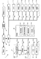
- FIG. 2 is a block diagram showing an example of the electrical configuration of the lighting device 1 shown in FIG.
- the lighting device 1 shown in FIG. 1 includes a solar cell sheet 3, a power generation amount detection unit 31, a BMS (Battery Management System) 32, a storage battery B, a power supply 33, a light emitting unit 4, a camera 5, an equipment unit 6, and a meteorological observation unit 7. It includes a wireless communication unit 8, a control unit 20, a switch SW0, and a plurality of switch SWs.
- BMS Battery Management System
- the equipment unit 6 includes a GPS 61 and an attitude sensor 62.
- the meteorological observation unit 7 includes a thermometer 71, a hygrometer 72, a wind direction meter 73, an anemometer 74, a sunshine meter 75, and a rain gauge 76 as sensors for acquiring information on the weather.
- the wireless communication unit 8 includes a mobile communication device 81, a wireless LAN device 82, and a relay device 83.
- the power generation amount detection unit 31 detects, for example, the output power P of the solar cell sheet 3 as the power generation amount of the solar cell sheet 3.
- the power generation amount detection unit 31 is not limited to the example of detecting electric power, and the physical quantity related to the power generation amount of the solar cell sheet 3, such as the output current or output voltage of the solar cell sheet 3, is the power generation amount of the solar cell sheet 3. It may be detected indirectly as.
- the storage battery B various secondary batteries such as a lithium ion secondary battery, a nickel hydrogen secondary battery, and a lead storage battery can be used.
- the BMS 32 is a so-called battery management system, which controls charging of the generated power by the solar cell sheet 3 to the storage battery B, controls discharge of the storage battery B to the power supply 33, and SOC (State Of Charge) of the storage battery B. Is detected and transmitted to the control unit 20.
- the BMS 32 corresponds to an example of a remaining amount detecting unit that detects the remaining amount of the storage battery B.
- SOC corresponds to an example of the remaining amount.
- the remaining amount is not limited to SOC (%), and may be, for example, the remaining capacity (Ah).
- the power supply 33 is, for example, a power supply circuit such as a switching power supply circuit.
- the power supply 33 converts the output voltage of the storage battery B into a light emitting voltage of the light emitting unit 4 and supplies the output voltage to the light emitting unit 4 via the switch SW0.
- the power supply 33 includes a GPS 61, an attitude sensor 62, a thermometer 71, a hygrometer 72, an anemometer 73, an anemometer 74, a pyranometer 75, a rain meter 76, a mobile communication device 81, a wireless LAN device 82, and a relay device.
- the output voltage of the storage battery B is converted into the operating voltage of each device unit of 83, and the operating voltage is supplied to each device unit via the switch SW connected to each device unit. Further, the power supply 33 converts the output voltage of the storage battery B into the operating voltage of the control unit 20 and supplies it to the control unit 20.
- GPS 61, attitude sensor 62, thermometer 71, hygrometer 72, wind direction meter 73, anemometer 74, sunshine meter 75, rain gauge 76, mobile communication device 81, wireless LAN device 82, and relay device 83 are electrical devices. Corresponds to one example.
- Switches SW0 and SW are switching elements such as semiconductor switching elements and relays, for example.
- the switches SW0 and SW are turned on and off according to the control signal from the control unit 20.
- the light emitting unit 4 is configured by using a light emitting element such as an LED (Light Emitting Diode).
- the camera 5 is configured by using, for example, a CMOS (Complementary Metal Oxide Semiconductor) image sensor, a CCD (Charge Coupled Device) image sensor, or the like.
- the camera 5 can be used as, for example, a surveillance camera.
- the GPS 61 corresponds to an example of a positioning device, acquires the position coordinates of the current position, and outputs the position coordinates to the control unit 20.
- the posture sensor 62 is configured by using, for example, a triaxial acceleration sensor, and outputs information indicating the posture of the lighting device 1 to the control unit 20. This makes it possible to detect when the support column 2 is tilted due to a storm, an accident, or the like.
- thermometer 71 Information indicating the temperature, humidity, wind direction, wind speed, sunshine amount, and rainfall amount measured by the thermometer 71, the hygrometer 72, the wind direction meter 73, the anemometer 74, the sunshine meter 75, and the rain gauge 76 is output to the control unit 20. Will be done.
- the mobile communication device 81 is a mobile communication device that performs mobile communication via a mobile communication operator.
- the wireless LAN device 82 is, for example, a wireless communication device that performs wireless communication by WiFi (registered trademark) (Wireless Fidelity).
- the wireless LAN device 82 corresponds to an example of a wireless communication device different from mobile communication.
- the control unit 20 is, for example, a non-volatile CPU (Central Processing Unit) that executes a predetermined arithmetic process, a RAM (RandomAccessMemory) that temporarily stores data, a flash memory that stores a predetermined control program and data, and the like. It is composed of a storage device and peripheral circuits thereof. The above-mentioned storage device is also used as the storage unit 24. Then, the control unit 20 functions as a light emission control unit 21, a power supply control unit 22, and a function control unit 23, for example, by executing a control program stored in the above-mentioned storage device.
- a non-volatile CPU Central Processing Unit
- RAM RandomAccessMemory
- the light emission control unit 21 periodically turns on and off the switch SW0 so as to turn off the switch SW0 for a period of less than 50 msec within one cycle. As a result, the light emitting control unit 21 periodically blinks the light emitting unit 4 in a cycle including an extinguishing period of less than 50 msec within one cycle based on the electric power charged in the storage battery B.
- the light emitting control unit 21 keeps the light emitting unit 4 blinking and sets the extinguishing reference value. If it exceeds the limit, the blinking of the light emitting unit 4 is stopped and the light emitting unit 4 is turned off. Further, when the light emission control unit 21 stops blinking and the power generation amount detected by the power generation amount detection unit 31 is less than the lighting reference value equal to or lower than the light emission reference value within the period when the light emitting unit 4 is turned off. , Start blinking of the light emitting unit 4.
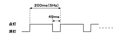
- FIG. 3 is a waveform diagram showing an example of the blinking cycle of the light emitting unit 4.
- the blinking cycle is 200 msec
- the frequency is 5 Hz
- the duty ratio is 24.5%
- the extinguishing period within one cycle is 49 msec, which is less than 50 msec.
- the light emitting unit 4 by periodically blinking the light emitting unit 4 in a cycle including an extinguishing period of less than 50 msec in one cycle, the light emitting unit 4 appears to be continuously lit to the human eye, and is necessary for lighting by the light emitting unit 4. Power consumption can be reduced.
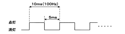
- FIG. 4 is a waveform diagram showing an example when the blinking frequency of the light emitting unit 4 is 100 Hz.
- the blinking cycle is 10 msec
- the frequency is 100 Hz
- the duty ratio is 50%
- the extinguishing period within one cycle is 5 msec, which is less than 50 msec.
- the flicker fusion frequency which is the limit of the frequency at which the human eye feels flickering with respect to blinking, is about 70 Hz to 100 Hz. Therefore, if the blinking frequency of the light emitting unit 4 is 100 Hz, although it overlaps with the upper limit of the flicker fusion frequency, stable light with almost no flicker is output except for extremely rare and sensitive people. Is possible. Therefore, the blinking frequency of the light emitting unit 4 is more preferably 100 Hz or higher. It is more preferable that the blinking frequency of the light emitting unit 4 exceeds 100 Hz because it does not overlap with the range of the flicker fusion frequency at all.
- the light emitting control unit 21 controls the blinking of the light emitting unit 4 based on the amount of power generated detected by the power generation amount detecting unit during the extinguishing period, so that the light emitting unit 4 blinks at night, for example, in the daytime. Since the lighting can be turned off when it becomes bright, the lighting device 1 can function as a street light.
- the lighting device 1 blinks the light emitting unit 4 and controls the blinking of the light emitting unit 4 based on the amount of power generated detected by the power generation amount detecting unit 31 within the extinguishing period, so that the light emitted from the light emitting unit 4 is used. No malfunction occurs. Therefore, the illuminance sensor for lighting control becomes unnecessary, and it becomes easy to reduce the cost.
- the function control unit 23 controls the operation of each of the above-mentioned electric devices. For example, the function control unit 23 transmits the information indicating the posture of the lighting device 1 detected by the posture sensor 62 to the outside by wireless communication by the mobile communication device 81 and / or the wireless LAN device 82. As a result, when the support column 2 is tilted due to a storm, an accident, or the like, the administrator of the lighting device 1 can be notified of this, so that maintenance management such as repairing the lighting device 1 becomes easy.
- the function control unit 23 transmits, for example, an image taken by the camera 5 to the outside by wireless communication by the mobile communication device 81 and / or the wireless LAN device 82. This makes it possible to monitor the image of the camera 5 from a remote location.
- the function control unit 23 wirelessly communicates the information of the temperature, humidity, wind direction, wind speed, sunshine amount, and rainfall amount observed by the meteorological observation unit 7 by the mobile communication device 81 and / or the wireless LAN device 82. Send to the outside with. This makes it easy to monitor natural disasters and the cultivation environment of agricultural crops.
- the function control unit 23 wirelessly communicates information on the operating state of the lighting device 1, such as the amount of power generated by the solar cell sheet 3 and the remaining amount of the storage battery B, by the mobile communication device 81 and / or the wireless LAN device 82. Send information to the outside with. This makes it easy to check the state of the lighting device 1 from the outside.
- the function control unit 23 adds the position information determined by GPS 61 when transmitting information to the outside by wireless communication by the mobile communication device 81 and / or the wireless LAN device 82. As a result, the place where the information is obtained can be specified, so that the convenience of utilizing the information is improved.
- the relay device 83 is a so-called relay device that relays communication between the mobile communication device 81 and the wireless LAN device 82. This makes it possible to use the lighting device 1 as an access point for WiFi (registered trademark) or the like. Then, since the user can access a wide area communication network such as the Internet via the mobile communication device 81 by using a wireless terminal device such as WiFi (registered trademark), the convenience of the user is improved.
- WiFi registered trademark
- FIG. 5 is an explanatory diagram showing an example of a remaining amount value table stored in the storage unit 24.
- the reference value table T shown in FIG. 5 includes a light emitting unit 4, a camera 5, a mobile communication device 81, a wireless LAN device 82, a relay device 83, a thermometer 71, a hygrometer 72, a wind direction meter 73, an anemometer 74, and a pyranometer.
- This is a lookup table in which the remaining amount reference value represented by SOC (%) is associated with each device unit of the 75, the rain gauge 76, the GPS 61, and the attitude sensor 62.
- the power supply control unit 22 refers to the reference value table T, and when the SOC of the storage battery B detected by the BMS 32 is less than any of the remaining amount reference values in the reference value table T, the power supply control unit 22 corresponds to the remaining amount reference value. By turning off the switches SW0 and SW connected to the attached device unit, the power supply is forcibly stopped.
- the power supply control unit 22 has priority over the light emission control unit 21 for the control of the switch SW0.
- the power supply control unit 22 stores the remaining amount reference value received from the user by the mobile communication device 81 or the wireless LAN device 82 in the reference value table T of the storage unit 24. As a result, the user can freely set and change the remaining amount reference value of each device unit.
- the remaining amount reference values of the GPS 61 and the attitude sensor 62 which are relatively insignificant, are 40%, and when the remaining amount of the storage battery B becomes low, the GPS 61 and the attitude sensor 62 are first charged. Power supply is stopped. As a result, it is possible to stop the less important device unit to reduce the power consumption and extend the operating time of the other device unit.
- the remaining amount reference value of the highly important device part such as the light emitting part 4 used for lighting a street lamp or the camera 5 used as a surveillance camera is 10%, and the remaining amount of the storage battery B becomes low. The power supply to the light emitting unit 4 and the camera 5 is continued until the last minute.
- the remaining amount reference value of the anemometer 74, the rain gauge 76, and the mobile communication device 81 that transmits these data used for monitoring natural disasters such as storms is 0%, and the remaining amount of the storage battery B is 0%. The operation is maintained until becomes 0.
- the power from the storage battery B can be supplied according to the priority of each device unit.
- the reference value table T shown in FIG. 5 is an example, and a desired remaining amount reference value may be appropriately set.
- the electric devices include a camera 5, a thermometer 71, a hygrometer 72, a wind direction meter 73, an anemometer 74, a pyranometer 75, a rain gauge 76, GPS 61, an attitude sensor 62, a mobile communication device 81, and a wireless LAN device 82.
- the relay device 83 may be at least one of these, or may be a device different from these.
- a display device such as a display panel used for digital signage may be provided as an electric device. Alternatively, these electric devices may not be provided.
- the power supply control unit 22 and the switch SW may not be provided, and the remaining amount detection unit may not be provided.
- the solar cell lighting system includes a solar cell, a storage battery that charges the power generated by the solar cell, a light emitting unit that emits light, and a power generation amount detecting unit that detects the amount of power generated by the solar cell.
- the light emitting control unit is provided with a light emitting control unit that periodically blinks the light emitting unit in a cycle including a light extinguishing period of less than 50 msec within one cycle based on the power charged in the storage battery, and the light emitting control unit is said to be extinguished.
- the blinking is continued, and if it exceeds the extinguishing reference value, the blinking is stopped and the light emission is emitted. Turn off the part.
- the blinking is continued and the light is brighter than the light-off reference value.
- the influence of the light of the light emitting unit generated by the solar cell can be eliminated, and the light emission of the light emitting unit can be controlled according to the brightness of the external environment.
- the extinguishing period in one cycle is less than 50 msec, the human eye does not perceive that the extinguishing is extinguished. Therefore, it is not necessary to provide an illuminance sensor as described in Patent Document 1, and it is easy to reduce the cost.
- the blinking frequency is preferably 100 Hz or higher.
- the power generation amount detected by the power generation amount detection unit satisfies the lighting reference value equal to or less than the light emission reference value within the period in which the blinking is stopped and the light emitting unit is turned off. If not, it is preferable to start the blinking.
- the light emitting part starts blinking. be able to.
- the electric device corresponds to at least one of the electric device that operates based on the electric power charged in the storage battery, the remaining amount detecting unit that detects the remaining amount of the storage battery, and the electric device and the light emitting unit.
- a storage unit that stores the remaining amount reference value, and a power supply control unit that forcibly stops the supply of the power to at least one of the storage batteries when the remaining amount of the storage battery is less than the remaining amount reference value. It is preferable to further prepare.
- the lower priority is stopped to reduce the power consumption based on the remaining amount reference value set according to the priority of the electric device and the light emitting unit.
- the other operating time can be extended.
- the electric device is a camera, a thermometer, a hygrometer, a wind direction meter, a wind speed meter, a pyranometer, a rain meter, a positioning device, an attitude sensor, a display device, a mobile communication device, and a wireless communication device different from mobile communication.
- the relay devices that relay the wireless communication device to the wide area communication network.
- the camera thermometer, hygrometer, wind direction meter, anemometer, pyranometer, rain gauge, positioning device, attitude sensor, display device, mobile communication device, wireless It is possible to control the presence / absence of power supply for at least one of the communication device and the relay device according to the corresponding remaining amount reference value.
- a substantially rod-shaped strut is further provided, the light emitting portion is attached near the tip of the strut, and the solar cell is wound around the outer periphery of the strut.
- a solar cell lighting system in which a light emitting part is attached near the tip of a support column and a solar cell is wound around the outer periphery of the support column is suitable as lighting that illuminates with the electric power generated by photovoltaic power generation.
- Lighting device (solar cell lighting system) 2 Prop 3 Solar cell sheet (solar cell) 4 Light emitting unit 5 Camera 6 Equipment unit 7 Meteorological observation unit 8 Wireless communication unit 9 Leg 10 Tip cover 11 Mounting unit 12 Opening 13 Lid 20 Control unit 21 Light emission control unit 22 Power supply control unit 23 Function control unit 24 Storage unit 31 Power generation amount detection unit 32 BMS (remaining amount detection unit) 33 Power supply 61 GPS (Positioning System) 62 Attitude sensor 71 Thermometer 72 Hygrometer 73 Wind direction meter 74 Anemometer 75 Pyranometer 76 Rain gauge 81 Mobile communication device 82 Wireless LAN device 83 Relay device B Storage battery SW switch SW0 Switch T Reference value table
Landscapes
- Engineering & Computer Science (AREA)
- General Engineering & Computer Science (AREA)
- Circuit Arrangement For Electric Light Sources In General (AREA)
- Arrangement Of Elements, Cooling, Sealing, Or The Like Of Lighting Devices (AREA)
- Photovoltaic Devices (AREA)
Abstract
Un dispositif d'éclairage (1) est pourvu d'une feuille de batterie solaire (3), d'une batterie de stockage (B) qui est chargée avec l'énergie générée par la feuille de batterie solaire (3), d'une unité d'émission de lumière (4) qui émet de la lumière, d'une unité de détection de quantité de génération d'énergie (31) qui détecte la quantité de génération d'énergie de la feuille de batterie solaire (3), et d'une unité de commande d'émission de lumière (21) qui, sur la base de l'énergie avec laquelle la batterie de stockage (B) est chargée, met en marche et arrête l'unité d'émission de lumière (4) cycliquement dans un cycle comprenant une période d'arrêt inférieure à 50 msec dans un cycle. L'unité de commande d'émission de lumière (21) continue le cycle de mise en marche et d'arrêt si la quantité de génération d'énergie détectée par l'unité de détection de la quantité de génération d'énergie (31) dans la période d'arrêt est inférieure à une valeur de référence d'arrêt prédéfinie, et si la quantité de génération d'énergie dépasse la valeur de référence d'arrêt, met fin au cycle de mise en marche et d'arrêt, et arrête l'unité d'émission de lumière (4).
Applications Claiming Priority (2)
| Application Number | Priority Date | Filing Date | Title |
|---|---|---|---|
| JP2020-036895 | 2020-03-04 | ||
| JP2020036895A JP2021140921A (ja) | 2020-03-04 | 2020-03-04 | 太陽電池照明システム |
Publications (1)
| Publication Number | Publication Date |
|---|---|
| WO2021177331A1 true WO2021177331A1 (fr) | 2021-09-10 |
Family
ID=77612612
Family Applications (1)
| Application Number | Title | Priority Date | Filing Date |
|---|---|---|---|
| PCT/JP2021/008058 Ceased WO2021177331A1 (fr) | 2020-03-04 | 2021-03-03 | Système d'éclairage à batterie solaire |
Country Status (2)
| Country | Link |
|---|---|
| JP (1) | JP2021140921A (fr) |
| WO (1) | WO2021177331A1 (fr) |
Families Citing this family (1)
| Publication number | Priority date | Publication date | Assignee | Title |
|---|---|---|---|---|
| JP7829521B2 (ja) * | 2023-06-29 | 2026-03-13 | 三菱電機ビルソリューションズ株式会社 | 照明制御システムおよび照明制御方法 |
Citations (4)
| Publication number | Priority date | Publication date | Assignee | Title |
|---|---|---|---|---|
| JP2003202263A (ja) * | 2002-01-07 | 2003-07-18 | Toshiba Electronic Systems Co Ltd | 街路灯不点灯検知装置 |
| JP2012094273A (ja) * | 2010-10-25 | 2012-05-17 | Panasonic Corp | 照明装置 |
| JP2015531974A (ja) * | 2012-10-30 | 2015-11-05 | エルジー・ケム・リミテッド | 太陽電池式照明装置の制御システム及び方法 |
| JP2018088373A (ja) * | 2016-11-29 | 2018-06-07 | パナソニックIpマネジメント株式会社 | 発光装置 |
Family Cites Families (1)
| Publication number | Priority date | Publication date | Assignee | Title |
|---|---|---|---|---|
| JP2013229298A (ja) * | 2012-03-28 | 2013-11-07 | Kume Electric Corp | 照明装置 |
-
2020
- 2020-03-04 JP JP2020036895A patent/JP2021140921A/ja active Pending
-
2021
- 2021-03-03 WO PCT/JP2021/008058 patent/WO2021177331A1/fr not_active Ceased
Patent Citations (4)
| Publication number | Priority date | Publication date | Assignee | Title |
|---|---|---|---|---|
| JP2003202263A (ja) * | 2002-01-07 | 2003-07-18 | Toshiba Electronic Systems Co Ltd | 街路灯不点灯検知装置 |
| JP2012094273A (ja) * | 2010-10-25 | 2012-05-17 | Panasonic Corp | 照明装置 |
| JP2015531974A (ja) * | 2012-10-30 | 2015-11-05 | エルジー・ケム・リミテッド | 太陽電池式照明装置の制御システム及び方法 |
| JP2018088373A (ja) * | 2016-11-29 | 2018-06-07 | パナソニックIpマネジメント株式会社 | 発光装置 |
Also Published As
| Publication number | Publication date |
|---|---|
| JP2021140921A (ja) | 2021-09-16 |
Similar Documents
| Publication | Publication Date | Title |
|---|---|---|
| ES2601752T3 (es) | Control de gestión de energía para dispositivos de iluminación alimentados con energía solar | |
| JP2012094273A (ja) | 照明装置 | |
| JP2013229298A (ja) | 照明装置 | |
| CN205390085U (zh) | 一种物联网可自由升降调节角度的太阳能频振式杀虫灯 | |
| CN112654112B (zh) | 可在物联网显示的led控制系统 | |
| KR101168922B1 (ko) | 유아등 트랩 | |
| CN107613251A (zh) | 监控系统、太阳能违法抓拍系统及其控制方法 | |
| WO2021177331A1 (fr) | Système d'éclairage à batterie solaire | |
| KR20090011586U (ko) | 본 고안은 환경상태 계측, 센서 상태 계측 ,영상 J-peg전송해서 볼 수 있고 그 모든 것이 SD 카드에 저장 되고네트워크 되는 지능형 태양광 LED 가로등 | |
| US8599031B2 (en) | Systems and methods for stray voltage detection | |
| CN206380828U (zh) | 一种具有摔倒自动扶起功能的智能拐杖 | |
| JP3161534U (ja) | 支柱の傾き監視システム | |
| JP5362631B2 (ja) | 無線送信装置 | |
| CN216212076U (zh) | 一种实现租赁led显示屏的智能监控系统 | |
| KR101246671B1 (ko) | 무선센서네트워크 기반 조명시스템 및 조명제어방법 | |
| CN213150001U (zh) | 智能信息采集装置 | |
| RU152282U1 (ru) | Автономный уличный осветитель | |
| KR20050028170A (ko) | 무인등대 원격관리시스템 | |
| CN111770605A (zh) | 一种智能灯和灯光控制系统 | |
| JP2012113879A (ja) | 照明装置 | |
| JPH04357908A (ja) | 照明装置付きベンチ | |
| JP2008257999A (ja) | 制御装置、及び照明システム | |
| CN115854527B (zh) | 智能空调及其控制方法 | |
| CN217825454U (zh) | 一种闪光信号灯控制装置 | |
| CN216315005U (zh) | 一种灯诱设备 |
Legal Events
| Date | Code | Title | Description |
|---|---|---|---|
| 121 | Ep: the epo has been informed by wipo that ep was designated in this application |
Ref document number: 21764029 Country of ref document: EP Kind code of ref document: A1 |
|
| NENP | Non-entry into the national phase |
Ref country code: DE |
|
| 122 | Ep: pct application non-entry in european phase |
Ref document number: 21764029 Country of ref document: EP Kind code of ref document: A1 |